EP0686800A1 - Quick-coupling fitting for pipes, provided with a safety valve - Google Patents
Quick-coupling fitting for pipes, provided with a safety valve Download PDFInfo
- Publication number
- EP0686800A1 EP0686800A1 EP19950201428 EP95201428A EP0686800A1 EP 0686800 A1 EP0686800 A1 EP 0686800A1 EP 19950201428 EP19950201428 EP 19950201428 EP 95201428 A EP95201428 A EP 95201428A EP 0686800 A1 EP0686800 A1 EP 0686800A1
- Authority
- EP
- European Patent Office
- Prior art keywords
- valve
- bush
- passage
- fitting
- coupling
- Prior art date
- Legal status (The legal status is an assumption and is not a legal conclusion. Google has not performed a legal analysis and makes no representation as to the accuracy of the status listed.)
- Granted
Links
Images


Classifications
-
- F—MECHANICAL ENGINEERING; LIGHTING; HEATING; WEAPONS; BLASTING
- F16—ENGINEERING ELEMENTS AND UNITS; GENERAL MEASURES FOR PRODUCING AND MAINTAINING EFFECTIVE FUNCTIONING OF MACHINES OR INSTALLATIONS; THERMAL INSULATION IN GENERAL
- F16L—PIPES; JOINTS OR FITTINGS FOR PIPES; SUPPORTS FOR PIPES, CABLES OR PROTECTIVE TUBING; MEANS FOR THERMAL INSULATION IN GENERAL
- F16L37/00—Couplings of the quick-acting type
- F16L37/28—Couplings of the quick-acting type with fluid cut-off means
- F16L37/30—Couplings of the quick-acting type with fluid cut-off means with fluid cut-off means in each of two pipe-end fittings
- F16L37/32—Couplings of the quick-acting type with fluid cut-off means with fluid cut-off means in each of two pipe-end fittings at least one of two lift valves being opened automatically when the coupling is applied
- F16L37/34—Couplings of the quick-acting type with fluid cut-off means with fluid cut-off means in each of two pipe-end fittings at least one of two lift valves being opened automatically when the coupling is applied at least one of the lift valves being of the sleeve type, i.e. a sleeve is telescoped over an inner cylindrical wall
-
- Y—GENERAL TAGGING OF NEW TECHNOLOGICAL DEVELOPMENTS; GENERAL TAGGING OF CROSS-SECTIONAL TECHNOLOGIES SPANNING OVER SEVERAL SECTIONS OF THE IPC; TECHNICAL SUBJECTS COVERED BY FORMER USPC CROSS-REFERENCE ART COLLECTIONS [XRACs] AND DIGESTS
- Y10—TECHNICAL SUBJECTS COVERED BY FORMER USPC
- Y10T—TECHNICAL SUBJECTS COVERED BY FORMER US CLASSIFICATION
- Y10T137/00—Fluid handling
- Y10T137/8593—Systems
- Y10T137/87917—Flow path with serial valves and/or closures
- Y10T137/87925—Separable flow path section, valve or closure in each
- Y10T137/87941—Each valve and/or closure operated by coupling motion
- Y10T137/87949—Linear motion of flow path sections operates both
Definitions
- the internal casing supports a valve element constituted by a fixed axial internal stem with an enlarged end. On the outside of the latter, concentrically, there is fitted, so as to leave an intermediate space in between, a sealing bush that, under the elastic action of positioning springs and by means of the engagement with the enlarged end of the stem, completely prevents the passage of fluid in the intermediate space in the absence of coupling with the male element.
- the internal casing 6, with spaces 17 for receiving the protruding elements 11 of the sealing bush 10, has a contact surface with the external casing 4 provided with a seal 8 and a contact surface with said sealing bush 10 provided with a further seal 19 and with an antiextrusion device 20.
- the external casing 29 has an internally-threaded terminal portion 62. In a more backward position, it also supports a ring nut 30, provided with a positioning spring 60 and sliding on the external surface of said terminal portion 62 of the external casing 29. In the proximity of the ring nut 30 the terminal portion 62 has externally an elastic ring 43, whose functions will appear clear later.
- the internal casing 32 translating toward the left, disengages itself from the piston 37 and engages the bush 10 taking the seal 40 into contact with the bush itself. Since the seat 39 is at a minimum distance from the end wall 48 of the casing 32, with a small axial displacement of the casing 32 the seal 10 is covered and protected by the bush 10 already during the initial stages of screwing up the fitting.
- the third stage of the coupling consists in the further screwing up of the element 2 on the element 1.
- the piston 37 due to the relative motion toward the left of the external casing 29 and of the internal casing 32, is now further to the rear with respect to the internal casing 32, with the consequent further compression of the positioning spring 38.
- the piston 37 comes into contact with the stem 72 of the valve 71 and drives it toward the right, compressing the valve 75 through the projection 76.
- the valve 71 thus starts to open the communication port 79 between conduit 65 and intermediate space 36, after which the passage port 78 is also open.
- the balls 23 no longer prevent the relative motion of the ring nut 30 with respect to the terminal portion 62 of the external casing 29; as a consequence the spring 60, no longer constrained by the presence of the balls 23, urges the ring nut itself to slide along the terminal portion 62 until it reaches the elastic ring 43 that prevents any further movement toward the left of said ring nut; this thus remains in a position of equilibrium, clamping the balls 23 inside the space 21.
- Such positioning of the ring nut 30 thus allows the fitting to be locked completely in the coupled position and completes the operations for the assembly of the fitting itself (Fig. 5).
Abstract
Description
- The present invention relates to a quick-coupling fitting for pipes, provided with a safety valve.
- In the transmission of fluids it is often necessary to have fittings available that can be coupled quickly to connect flexible or rigid pipes, in turn connected to a supply of fluid and to a user.
- Known quick-coupling fittings are generally constituted by two elements, male and female, fitted to respective pipes to be connected and connectable by screwing or by snap-on means.
- According to a currently known art the female element has a structure comprising an internal casing inserted at one end in an internally threaded nut for connecting either to the supply or to the user and an external casing coaxial with said internal casing.
- The internal casing supports a valve element constituted by a fixed axial internal stem with an enlarged end. On the outside of the latter, concentrically, there is fitted, so as to leave an intermediate space in between, a sealing bush that, under the elastic action of positioning springs and by means of the engagement with the enlarged end of the stem, completely prevents the passage of fluid in the intermediate space in the absence of coupling with the male element.
- Concentrically with and externally to the bush, there is a unit for cleaning the same constituted by a sliding cup with a corresponding positioning spring.
- To the internal casing, between it and a rearward portion of the axial stem, there is constrained an annular element with spokes in which six holes of a small diameter are drilled for the passage of the fluid. As an alternative, with the object of avoiding the turbulence associated with the presence of small-diameter holes, such annular element can be provided with at least two passage ports in the shape of an annular sector one after the other, interspaced by narrow spokes, along a circumference of said annular element.
- The male element generally comprises an external casing provided with means for coupling up with the female element at one end, an internal casing and an internally-threaded nut at the other end for coupling up with the supply or the user. Inside said casing, in a concentric position such as to leave an intermediate space in between, there is a piston urged by corresponding positioning springs in a front-closing position of the intermediate space itself.
- During the coupling action between the female fitting and the male fitting, the sliding cup of the female element is driven by the external casing of the male element and, during its translation, it carries the bush along with it against the force exerted by the positioning spring corresponding to it. At the same time the piston of the male element is urged to return inside the external casing of the male element itself against the force of the corresponding positioning spring to a position where the intermediate space is open.
- As regards the coupling action between the male and female element of the fitting, this can be obtained by means of snap-on coupling means or by screwing, using appropriate threads on the outside of the female element and inside a terminal cavity of the male element.
- A fitting of the type described above has formed the object of the European patent application EP-0580233 filed in the name of the same Applicant.
- In this fitting the operating pressures of the service fluid in the pipe are high; maximum values vary from 180 bar to 600 bar, according to the type of use. During the coupling action, it can occur that an element, for example the male element, is under pressure, and the other, the female element, is not. Inside the fitting a difference in pressure can take place that is so high that it can jeopardise the internal seals remaining in their seat. This takes place, in particular, in the case of a seal housed in a seat of the internal casing of a male element under pressure engaged with the bush of a female element not under pressure. In fact, since the seat of the seal is usually at some distance from the end of the male element faciong the bush, it can happen that the seal remains uncovered and is exposed to the flow of fluid under pressure during the axial translation made by the internal casing to engage with the bush, especially if the difference in pressure causes a displacement of the bush in the opposite direction. Due to the high difference in pressure, the seal is subjected to such stresses that it is torn from its seat. The consequent loss of the sealing action between the internal casing and the bush causes losses and leaks of fluid through the fitting.
- The object of the present invention is to provide a quick-coupling fitting of the type described above, that is capable of guaranteeing the seal even under coupling conditions such as those described above.
- According to the invention, such object is attained by means of a quick-coupling fitting comprising a female element and a male element that can be coupled together, which elements are formed by fixed parts and axially sliding parts that when at rest are arranged in a closed position of a passage port for the fluid and on the occasion when the two elements are coupled together are displaced by engagement with corresponding parts of the other element in a position where said passage port is open, said sliding parts of the female element comprising a bush that is axially sliding and elastically urged toward said closed position and said fixed parts of the male element comprising a fixed internal casing provided with a seal that can be covered by said bush of the female element on the occasion of said coupling action, characterised in that said male element comprises valve means apt for intercepting a supply conduit of said passage port of fluid in the initial stages of said coupling action and apt for opening a communication port between said conduit and said passage port in the final stages of said coupling action, and said seal is housed in a seat located in the proximity of one end of said internal casing facing said bush, so that said seal is covered by said bush whatever is the axial position assumed by said bush during said initial and final stages of said coupling action.
- The presence of valve means and the positioning of the seal in a seat near the end of the internal casing of the male element prevent the seal from being exposed to dangerous stresses due to possible high differences in pressure between the two elements, because the passage of fluid through the fitting is allowed only when the seal is sure to be covered and protected by the bush. In fact, the seal remains protected by the bush even if the bush moves backward temporarily due to the effect of the high differences in pressure. Thus, the seal remains in its seat and carries out its function correctly even under particular conditions of coupling action, when the male element is under pressure and the female element is not, without there being any losses and leaks of fluid from the fitting.
- These and other features of the present invention will be made more evident by the following detailed description of an embodiment thereof, illustrated as a non-limiting example in the enclosed drawings, wherein:
- Fig. 1 is a front view, partially sectioned longitudinally, of a female element and of a male element of a fitting according to the invention;
- Fig. 2 is a front view, partially sectioned longitudinally, of the fitting according to the invention, in a first stage of the coupling movement;
- Fig. 3 is a front view, partially sectioned longitudinally, of the fitting according to the invention, in a second stage of the coupling movement;
- Fig. 4 is a front view, partially sectioned longitudinally, of the fitting according to the invention, in a third stage of the coupling movement;
- Fig. 5 is a front view, partially sectioned longitudinally, of the fitting according to the invention, as it appears after the two male and female elements are coupled and locked together;
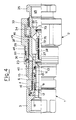
- Fig. 6 is a front view, partially sectioned longitudinally, of a female element and of a male element of a variant of the fitting according to the invention;
- Fig. 7 is a front view, partially sectioned longitudinally, of the fitting of Fig. 6, in an intermediate stage of the coupling movement;
- Fig. 8 is a front view, partially sectioned longitudinally, of the fitting of Fig. 6 with the two male and female elements coupled and locked together.
- With reference to Fig. 1, the fitting according to the invention is constituted by a female element 1 and by a
male element 2. - The female element 1 comprises, rigidly clamped together, a
nut 3 provided with an internal thread for coupling to a supply of fluid or to a user, anexternal casing 4 screwed intosaid nut 3 at one end, a fixedannular base 18 withseveral ports 63 for the passage of the fluid and aninternal casing 6, arranged concentrically with respect to theexternal casing 4. The perfect seal between saidexternal casing 4 and saidnut 3 is guaranteed by a seal 7. - The
annular base 18 supports a fixed axialinner stem 9. Externally to and concentrically with thestem 9, so as to leave anintermediate space 61, there is an axially sliding sealingbush 10, provided with protrudingelements 11; under conditions at rest, with the fitting open, said sealingbush 10 is urged, in the axial direction, by aspring 12 that drives saidbush 10 toward the right, through asleeve 64; the engagement with an enlargedend 13 of thestem 9 balances the force exerted by thespring 12 and keeps thebush 10 in a condition of equilibrium. - With the enlarged
end 13 of thestem 9 there is associated aseal 14 that prevents the passage of the fluid under conditions at rest. - Concentrically with and externally to the sealing
bush 10 and inside theexternal casing 4, there is a unit for cleaning the bush itself, formed by acup 15, provided with a transversal terminal element 51, axially sliding on the external surface of saidinternal casing 6 and urged by apositioning spring 16. - The
internal casing 6, withspaces 17 for receiving theprotruding elements 11 of thesealing bush 10, has a contact surface with theexternal casing 4 provided with a seal 8 and a contact surface with said sealingbush 10 provided with afurther seal 19 and with anantiextrusion device 20. - The
external casing 4, at the end at which it is coupled with themale element 2, has anexternal thread 5. It also, again on its own external surface, has anannular space 21 for receiving a circumferential succession ofballs 23 carried by themale element 2. - The
terminal surfaces external casing 4, of thecup 15 and of theaxial stem 9, respectively, are arranged to form a flat surface indicated globally with 28. - The
male fitting element 2 comprises anexternal casing 29, aninternal casing 32, arranged concentrically to saidexternal casing 29, aterminal nut 35 screwed into theinternal casing 32, provided with aconduit 65 for connecting to a supply or to a user, and a supportingelement 34, scrwed into theexternal casing 29 and sliding on the external surface of theterminal nut 35 under the action of aspring 33. Thenut 35 is provided with a frustum-shaped shoulder 66, havingseveral ports 67 passing through it for the passage of the fluid, and with atubular element 68. Thenut 35 and theinternal casing 32, that constitute fixed parts of themale element 2, define inside them acavity 36 for the passage of the fluid, wherein there is housed apiston 37 urged by aspring 38 in an axial direction. The seal between theinternal casing 32 and thepiston 37 is guaranteed by aseal 40, formed by an elastic ring and by an O-ring, that is housed in anannular seat 39 of thecasing 32. Theseat 39 is in the proximity of anend surface 48 facing thebush 10. Theseat 39 is located at a predeterminated minimum distance from theend surface 48, for example equal to 0.5 mm or even less. Thepiston 37 remains in contact with theinternal casing 32 so as to close a port for the passage of thefluid 78 betweencavity 36 andspace 61. - The
piston 37 has askirt 70 that is slidably supported axially in thetubular element 68. Coaxial with theskirt 70 there is amushroom valve 71 provided with astem 72 and with ahead 73, having an annular seal 74 (that can, however, be replaced with an appropriate metal-to-metal seal). Thevalve 71 is kept up against the frustum-shaped shoulder 66 by aspring 75, so as to intercept apassage port 79 between theconduit 75 and thecavity 36. Thespring 75 is interposed between anannular projection 76 fastened to thestem 72 and astriker wall 77 of thetubular element 78. Thespring 38 acting on thepiston 37 is also engaged with theannular projection 76 of thestem 75. - In the intermediate space between the
external casing 29 and theinternal casing 32 there is acup 44 urged by a positioningspring 45 acting up against aring 46 held between theexternal casing 29 and the supportingelement 34. - The
external casing 29 has an internally-threadedterminal portion 62. In a more backward position, it also supports aring nut 30, provided with apositioning spring 60 and sliding on the external surface of saidterminal portion 62 of theexternal casing 29. In the proximity of thering nut 30 theterminal portion 62 has externally anelastic ring 43, whose functions will appear clear later. - On the internal surface the
ring nut 30 has anannular notch 41 apt for defining, in the position at rest shown in Fig. 1 and jointly with a corresponding succession ofholes 42 of theexternal casing 29, respective spaces for receiving theballs 23 for fastening said male 2 and female 1 elements. - The
terminal surfaces cup 44, of theinternal casing 32 and of thepiston 37, respectively, are arranged so as to form a flat surface indicated globally with 50. - Beginning with the position at rest of the two female 1 and male 2 elements of the fitting according to the invention, illustrated in Fig. 1, the coupling action is executed as follows.
- With reference to Fig. 2, the coupling of the fitting starts with the
elements 1 and 2 being brought together so that therespective surfaces surface 27 of theenlarged end 13 of thestem 9 is placed in contact with thesurface 49 of thepiston 37, thesurface 26 of the vertical element 51 of thecup 15 is placed in contact with theterminal surface 48 of theinternal casing 32 of themale element 2 and lastly thesurface 25 of theexternal casing 4 is placed in contact with thesurface 47 of thecup 44. - The first stage of the coupling action then provides for the start of the screwing action of the terminal threaded
portion 62 of theexternal casing 29 of themale element 2 on the corresponding threadedportion 5 of theexternal casing 4 of said female element 1. Such screwing action causes in the first place the displacement toward the left, with respect to the at rest position, of theexternal casing 29, sliding on theinternal casing 32, and of thesupport 34, sliding on thenut 35. The motion of thesupport 34 causes a compression of thespring 33 and, at the same time, it involves in the motion thering 46 that urges thespring 45 to compression. - During this first stage the passage of the fluid inside the fitting is prevented on the basis of the fact that the
intermediate space 61 of the female element 1 is closed due to the engagement between thebush 10 and theenlarged end 13 of thestem 9, thecavity 36 of themale element 2 is closed by thepiston 37 and theconduit 65 is closed by thevalve 71. - With reference to Fig. 3, the second stage of the coupling action consists in the continuation of the screwing up operations.
- The
external casing 29 and itsterminal portion 62 continue to advance toward the left. The attainment of the position of maximum compression of thespring 33 makes thesupport 34 perfectly integral with theexternal casing 32 that, as a consequence, is driven toward the left, against the action of thespring 16 that urges thecup 15 in contact with saidcasing 32. Thecup 15 moves toward the left, approaching the protrudingelements 11 of thebush 10, and thespring 16 is, thus, compressed as a result of the displacement of saidcup 15. - The
internal casing 32, translating toward the left, disengages itself from thepiston 37 and engages thebush 10 taking theseal 40 into contact with the bush itself. Since theseat 39 is at a minimum distance from theend wall 48 of thecasing 32, with a small axial displacement of thecasing 32 theseal 10 is covered and protected by thebush 10 already during the initial stages of screwing up the fitting. Thebush 10, through the engagement with theenlarged end 13 of thestem 9, continues to keep thepassage port 78 closed betweencavity 36 andintermediate space 61. - The relative motion between the
internal casing 32 and thestem 9, that remains fixed together with itsenlarged end 13, brings thepiston 37 to a position further to the rear in themale element 2, with the consequent compression of thecorresponding positioning spring 38, while thevalve 71, in the case of pressure in theconduit 65, continues to keep closed thecommunication port 79 betweenconduit 65 andcavity 36. - At the same time the
cup 44, kept in contact with theexternal casing 4, urges a further compression of thespring 45. - With reference to Fig. 4, the third stage of the coupling consists in the further screwing up of the
element 2 on the element 1. - The
piston 37, due to the relative motion toward the left of theexternal casing 29 and of theinternal casing 32, is now further to the rear with respect to theinternal casing 32, with the consequent further compression of thepositioning spring 38. Before thepassage port 78 betweencavity 36 andintermediate space 61 starts to open, thepiston 37 comes into contact with thestem 72 of thevalve 71 and drives it toward the right, compressing thevalve 75 through theprojection 76. Thevalve 71 thus starts to open thecommunication port 79 betweenconduit 65 andintermediate space 36, after which thepassage port 78 is also open. - If the fluid in the
conduit 65 is under pressure, while theintermediate space 61 is not, there is a very high difference in pressure that causes a movement toward the left of thebush 10, as shown in Fig. 4. It can be seen that even under these extreme conditions theseal 40 remains covered by thebush 10. Thus whatever the axial position of thebush 10 is during the final stages of the coupling of the fitting, theseal 40 remains covered by the bush itself. - With reference to Fig. 5, when the difference in pressure between the
conduit 65 and theintermediate space 61 is eliminated, thebush 10 is driven by thespring 12 toward the right, so that the vertical structure 51 of thecup 15 returns in contact with the protrudingelements 11, that act as a shoulder for the structure 51. - The last stage of the coupling action of the fitting consists in terminating the operations of screwing up the
external casing 29 on theexternal casing 4, which brings theinternal casing 32 to drive thecup 15 toward the left against the action of thespring 16. Thecasing 32, through the structure 51 and theprotruding elements 11, causes thebush 10 to be displaced toward the left. Such displacement has as a consequence the complete opening of thepassage port 78 between thecavity 36 and theintermediate space 61. - Moreover, the last stage of the screwing up of the
external casing 29 brings thepiston 37 to urge thestem 72 of thevalve 71 toward the right, completely opening thecommunication port 79 as well. Since thepassage port 78 and thecommunication 79 are both open, the fluid can flow through the entire fitting from theconduit 65 to theintermediate space 61. - A consequence of such further screwing up consists in reaching the maximum compression of the
spring 45, urged by thecup 44 that is pushed toward the right in relation to the leftward motion of theinternal casing 32 of themale element 2. In this position theexternal casing 29 and theinternal casing 32 of themale element 2 are displaced toward the left by an amount such as to allow theballs 23 to be arranged opposite theannular receiving space 21 of theexternal casing 4 of the female element 1. Theballs 23 protrude from theannular notch 41 of thering nut 30 and penetrate inside theannular space 21, with the consequent positioning of theballs 23 at a radial distance that is smaller than that of the previous position. Thus, in such new position theballs 23 no longer prevent the relative motion of thering nut 30 with respect to theterminal portion 62 of theexternal casing 29; as a consequence thespring 60, no longer constrained by the presence of theballs 23, urges the ring nut itself to slide along theterminal portion 62 until it reaches theelastic ring 43 that prevents any further movement toward the left of said ring nut; this thus remains in a position of equilibrium, clamping theballs 23 inside thespace 21. Such positioning of thering nut 30 thus allows the fitting to be locked completely in the coupled position and completes the operations for the assembly of the fitting itself (Fig. 5). - There is shown in Figs. 6-8 a variant of the fitting shown in Figs. 1-5, wherein the same parts are indicated with the same numbers.
- In this case, the
male element 2 has amushroom valve 80 with ahead 86 and two stems 81 and 82. Thepiston 37 has ashank 83 that interacts with thestem 81 of thevalve 80 and is axially slidably supported by a fixedannular element 84, withports 85 for the passage of the fluid, through the intermediary of thespring 38. Thevalve 80 is axially slidably supported by theannular element 84 and by a second fixedannular element 87 withports 88 for the passage of the fluid, through the intermediary of aspring 89. At rest (Fig. 6), thevalve 80 is kept up against the frustum-shapedshoulder 66 of thenut 35. - Assembling the fitting of Figs. 6-8 is altogether the same as that of the fitting of Figs. 1-5. In the final screwing up stages of the
external casing 29, when theseal 40 is covered by thebush 10, thepiston 37 opens thevalve 80 through the thrust of itsshank 83 on the stem 81 (Figs. 7 and 8).
Claims (7)
- Quick-coupling fitting for pipes, comprising a female element (1) and a male element (2) that can be coupled together, which elements (1, 2) are formed by fixed parts (3, 4, 6, 9; 29, 32, 35) and axially sliding parts (10, 15; 37, 44) that when at rest are arranged in a closed position of a passage port (78) for the fluid and on the occasion when the two elements (1, 2) are coupled together are displaced by engagement with corresponding parts of the other element in a position where said passage port (78) is open, said sliding parts (10, 15) of the female element (1) comprising a bush (10) that is axially sliding and elastically urged toward said closed position and said fixed parts (29, 32) of the male element (2) comprising a fixed internal casing (32) provided with a seal (40) that can be covered by said bush (10) of the female element (1) on the occasion of said coupling action, characterised in that said male element (2) comprises valve means (71; 80) apt for intercepting a supply conduit (65) of said passage port (78) in the initial stages of said coupling action and apt for opening a communication port (79) between said conduit (65) and said passage port (78) in the final stages of said coupling action, and said seal (40) is housed in a seat (39) located in the proximity of one end (48) of said internal casing (32) facing said bush (10), so that said seal (40) is covered by said bush (10) whatever is the axial position assumed by said bush (10) during said initial and final stages of said coupling action.
- Fitting according to claim 1, characterized in that said valve means (71) are constituted by a mushroom valve (71) comprising a stem (72) and a head (73), said valve (71) being capable of being engaged by an axially sliding piston (37) apt for opening said passage port (78) in said final stages of the coupling action.
- Fitting according to claim 2, characterized in that said piston (37) has a skirt (70) axially slidably supported in a tubular element (68) provided with a striker wall (77), integral with a terminal nut (35) comprising said supply conduit (65), said stem (72) of said valve (71) being provided with an annular projection (76), first elastic means (38) being interposed between said piston (37) and said annular projection (76), second elastic means (75) being interposed between said annular projection (76) and said striker wall (77).
- Fitting according to claim 3, characterized in that said head (73) of said valve is kept up against a frustum-shaped shoulder (66) integral with said terminal nut (35) by said second elastic means (75), so as to close said communication port (79).
- Fitting according to claim 4, characterized in that said frustum-shaped shoulder (66) is provided with ports (67) for the passage of the fluid.
- Fitting according to claim 1, characterized in that said valve means (80) are constituted by a mushroom valve comprising a head (86) and two stems (81, 82), said valve (80) being capable of being engaged by an axially sliding piston (37) apt for opening said passage port (78) in said final stages of the coupling action.
- Fitting according to claim 6, characterized in that said piston (37) has a shank (83) that interacts with a stem (81) of said mushroom valve (80) and is axially slidably supported by an annular element (84), with ports (85) for the passage of the fluid, through the intermediary of elastic means (38), said stems (81, 82) of said valve (80) being axially slidably supported by said annular element (84) and by a second annular element (87), with ports (88) for the passage of the fluid, through the intermediary of second elastic means (89), said second elastic means (89) keeping said valve (80) in abutment against a frustum-shaped shoulder (66) integral with a terminal nut (35) comprising said supply conduit (65), so as to close said communication port (79).
Applications Claiming Priority (2)
| Application Number | Priority Date | Filing Date | Title |
|---|---|---|---|
| IT001190 IT1270182B (en) | 1994-06-08 | 1994-06-08 | QUICK COUPLING FITTING FOR PIPES, EQUIPPED WITH A SAFETY VALVE |
| ITMI941190 | 1994-06-08 |
Publications (2)
| Publication Number | Publication Date |
|---|---|
| EP0686800A1 true EP0686800A1 (en) | 1995-12-13 |
| EP0686800B1 EP0686800B1 (en) | 1999-04-07 |
Family
ID=11369072
Family Applications (1)
| Application Number | Title | Priority Date | Filing Date |
|---|---|---|---|
| EP19950201428 Expired - Lifetime EP0686800B1 (en) | 1994-06-08 | 1995-05-31 | Quick-coupling fitting for pipes, provided with a safety valve |
Country Status (9)
| Country | Link |
|---|---|
| US (1) | US5592970A (en) |
| EP (1) | EP0686800B1 (en) |
| JP (1) | JP3258528B2 (en) |
| AT (1) | ATE178699T1 (en) |
| CA (1) | CA2151077C (en) |
| DE (1) | DE69508845T2 (en) |
| DK (1) | DK0686800T3 (en) |
| ES (1) | ES2130516T3 (en) |
| IT (1) | IT1270182B (en) |
Cited By (7)
| Publication number | Priority date | Publication date | Assignee | Title |
|---|---|---|---|---|
| EP0744572A1 (en) * | 1995-05-26 | 1996-11-27 | STUCCHI S.r.l. | Quick-coupling fitting for pipes |
| DE19624365C1 (en) * | 1996-06-19 | 1997-10-23 | Voswinkel Gmbh | Two part pressure coupling |
| WO1998019097A1 (en) * | 1996-10-25 | 1998-05-07 | Stucchi S.R.L. | Quick coupling pipe fitting with safety valve and pressure relieve valve |
| EP0862010A1 (en) * | 1997-02-21 | 1998-09-02 | FASTER S.r.l. | Quick-release coupling |
| WO2000004316A1 (en) * | 1998-07-17 | 2000-01-27 | Noel Ian Currin | Quick-acting coupling for fluid transporting pipes |
| EP2282103A1 (en) | 2009-08-07 | 2011-02-09 | Stucchi S.p.A. | Quick coupling with antirelease safety device |
| WO2011015588A1 (en) | 2009-08-07 | 2011-02-10 | Stucchi S.P.A. | Quick coupling with flow deviation device |
Families Citing this family (19)
| Publication number | Priority date | Publication date | Assignee | Title |
|---|---|---|---|---|
| SE506405C2 (en) * | 1996-03-22 | 1997-12-15 | Nyberg Bo Erik | Quick release with pressure relief for safe release |
| SE506346C2 (en) * | 1996-04-03 | 1997-12-08 | Nyberg Bo Erik | Quick connection for hoses or wires for print media |
| IT1290559B1 (en) * | 1997-02-28 | 1998-12-10 | Omba S R L | MECHANISM TO JOIN VALVE PARTS |
| US6095190A (en) * | 1998-11-17 | 2000-08-01 | Snap-Tite Technologies, Inc. | Coupling with female half having internal pressure relief |
| US6145539A (en) * | 1999-04-12 | 2000-11-14 | Snap-Tite Technologies, Inc. | Balanced coupling with pressure bleed |
| US6382251B1 (en) | 2000-03-29 | 2002-05-07 | Snap-Tite Technologies, Inc. | Coupling with male half having internal pressure relief |
| TWM242637U (en) * | 2002-05-17 | 2004-09-01 | Asia Pacific Fuel Cell Tech | Fast joint for hydrogen fuel bottle and adaptor apparatus for hydrogen fuel bottle with the same |
| JP3878903B2 (en) | 2002-10-25 | 2007-02-07 | 日東工器株式会社 | Pipe fitting |
| US7401626B1 (en) * | 2004-11-18 | 2008-07-22 | Plattner Wesley M | Low air inclusion quick disconnect coupling |
| ITMI20051521A1 (en) * | 2005-08-03 | 2007-02-04 | Stucchi Spa | FEMALE ELEMENT FOR QUICK COUPLING FITTING FOR PIPING |
| US7575024B2 (en) * | 2005-11-05 | 2009-08-18 | Snap-Tite Technologies, Inc. | Threaded coupling with flow shutoff |
| US7762279B2 (en) | 2005-11-05 | 2010-07-27 | Snap-Tite Technologies, Inc. | Threaded coupling with flow shutoff |
| KR100964254B1 (en) * | 2008-03-06 | 2010-06-16 | 우성전기공업 주식회사 | Electromagnet water supply valve |
| US8191575B2 (en) * | 2008-04-11 | 2012-06-05 | International Business Machines Corporation | Double poppet quick connect |
| GB2528013A (en) * | 2013-05-01 | 2016-01-06 | Parker Hannifin Corp | Twist-to-connect dry break coupling |
| CA2895873C (en) * | 2014-06-30 | 2019-01-08 | Parker-Hannifin Corporation | Inline connect breakaway hose coupler |
| US9976659B2 (en) | 2015-06-01 | 2018-05-22 | Holmbury, Ltd. | Decompression coupling block |
| FR3080165B1 (en) * | 2018-04-12 | 2020-05-01 | Staubli Faverges | FITTING ELEMENT AND FITTING COMPRISING SUCH A FITTING ELEMENT |
| FR3082588B1 (en) * | 2018-06-15 | 2020-09-11 | Staubli Sa Ets | FLUIDIC CONNECTION |
Citations (3)
| Publication number | Priority date | Publication date | Assignee | Title |
|---|---|---|---|---|
| US5191914A (en) * | 1991-05-30 | 1993-03-09 | Fairchild Space And Defense Corporation | Redundant valve disconnect coupling |
| EP0542342A1 (en) * | 1991-11-11 | 1993-05-19 | STUCCHI S.r.l. | Female fitting for various fluids |
| EP0580233A1 (en) * | 1992-07-22 | 1994-01-26 | STUCCHI S.r.l. | Quick-coupling pipe fitting |
Family Cites Families (4)
| Publication number | Priority date | Publication date | Assignee | Title |
|---|---|---|---|---|
| US3464436A (en) * | 1967-09-05 | 1969-09-02 | Earl F Bruning | Self-cleaning fluid coupling |
| SE447157B (en) * | 1985-03-13 | 1986-10-27 | Thure Ekman | COUPLING |
| US5063965A (en) * | 1989-05-19 | 1991-11-12 | Snap-Tite, Inc. | Quick disconnect coupling |
| US5123446A (en) * | 1991-07-05 | 1992-06-23 | Aeroquip Corporation | Dual seal coupling |
-
1994
- 1994-06-08 IT IT001190 patent/IT1270182B/en active IP Right Grant
-
1995
- 1995-05-31 AT AT95201428T patent/ATE178699T1/en active
- 1995-05-31 ES ES95201428T patent/ES2130516T3/en not_active Expired - Lifetime
- 1995-05-31 EP EP19950201428 patent/EP0686800B1/en not_active Expired - Lifetime
- 1995-05-31 DE DE1995608845 patent/DE69508845T2/en not_active Expired - Lifetime
- 1995-05-31 DK DK95201428T patent/DK0686800T3/en active
- 1995-06-05 US US08/463,057 patent/US5592970A/en not_active Expired - Lifetime
- 1995-06-06 CA CA 2151077 patent/CA2151077C/en not_active Expired - Lifetime
- 1995-06-08 JP JP14157395A patent/JP3258528B2/en not_active Expired - Lifetime
Patent Citations (3)
| Publication number | Priority date | Publication date | Assignee | Title |
|---|---|---|---|---|
| US5191914A (en) * | 1991-05-30 | 1993-03-09 | Fairchild Space And Defense Corporation | Redundant valve disconnect coupling |
| EP0542342A1 (en) * | 1991-11-11 | 1993-05-19 | STUCCHI S.r.l. | Female fitting for various fluids |
| EP0580233A1 (en) * | 1992-07-22 | 1994-01-26 | STUCCHI S.r.l. | Quick-coupling pipe fitting |
Cited By (9)
| Publication number | Priority date | Publication date | Assignee | Title |
|---|---|---|---|---|
| EP0744572A1 (en) * | 1995-05-26 | 1996-11-27 | STUCCHI S.r.l. | Quick-coupling fitting for pipes |
| DE19624365C1 (en) * | 1996-06-19 | 1997-10-23 | Voswinkel Gmbh | Two part pressure coupling |
| WO1998019097A1 (en) * | 1996-10-25 | 1998-05-07 | Stucchi S.R.L. | Quick coupling pipe fitting with safety valve and pressure relieve valve |
| US6026857A (en) * | 1996-10-25 | 2000-02-22 | Stucchi S.R.L. | Quick coupling pipe fitting with safety valve and pressure relieve valve |
| CN1075618C (en) * | 1996-10-25 | 2001-11-28 | 斯图奇公司 | Quick coupling pipe fitting with safety valve and pressure relieve valve |
| EP0862010A1 (en) * | 1997-02-21 | 1998-09-02 | FASTER S.r.l. | Quick-release coupling |
| WO2000004316A1 (en) * | 1998-07-17 | 2000-01-27 | Noel Ian Currin | Quick-acting coupling for fluid transporting pipes |
| EP2282103A1 (en) | 2009-08-07 | 2011-02-09 | Stucchi S.p.A. | Quick coupling with antirelease safety device |
| WO2011015588A1 (en) | 2009-08-07 | 2011-02-10 | Stucchi S.P.A. | Quick coupling with flow deviation device |
Also Published As
| Publication number | Publication date |
|---|---|
| IT1270182B (en) | 1997-04-29 |
| ES2130516T3 (en) | 1999-07-01 |
| DE69508845T2 (en) | 1999-08-26 |
| ATE178699T1 (en) | 1999-04-15 |
| ITMI941190A0 (en) | 1994-06-08 |
| DE69508845D1 (en) | 1999-05-12 |
| CA2151077C (en) | 2003-08-19 |
| JP3258528B2 (en) | 2002-02-18 |
| EP0686800B1 (en) | 1999-04-07 |
| JPH0854089A (en) | 1996-02-27 |
| US5592970A (en) | 1997-01-14 |
| DK0686800T3 (en) | 1999-10-18 |
| CA2151077A1 (en) | 1995-12-09 |
| ITMI941190A1 (en) | 1995-12-08 |
Similar Documents
| Publication | Publication Date | Title |
|---|---|---|
| US5592970A (en) | Quick-coupling fitting for pipes provided with a safety valve | |
| US6026857A (en) | Quick coupling pipe fitting with safety valve and pressure relieve valve | |
| US5662141A (en) | Leak-resistant fluid coupling arrangement | |
| US5015016A (en) | Internal pressure loaded V-seal connector | |
| US3664634A (en) | Valve seal for coupling device | |
| US4921013A (en) | Coupling adapter | |
| US4817668A (en) | Integral metal seal for hydraulic coupling | |
| US4077433A (en) | Quick coupling device | |
| AU685244B2 (en) | Undersea hydraulic coupling with metal seals | |
| GB2286643A (en) | Undersea Hydraulic coupling with pre-sealing guidance | |
| US6056010A (en) | Anti-check low spill fluid coupling | |
| GB2277357A (en) | Hydraulic coupling with hollow metal o-ring seal | |
| US5950679A (en) | High pressure plug coupling | |
| GB2348936A (en) | Undersea hydraulic coupling | |
| GB2299839A (en) | Undersea hydraulic coupling with hollow metal seal | |
| EP0580233B1 (en) | Quick-coupling pipe fitting | |
| US5855227A (en) | Quick-coupling fitting for pipes with an improved seal | |
| GB2362199A (en) | Undersea hydraulic coupling with seal retainer having an L-shaped fluid passage | |
| US4786029A (en) | Connect-against-pressure coupling | |
| EP0958468A2 (en) | Farm coupling | |
| AU728363C (en) | Quick coupling pipe fitting with safety valve and pressure relieve valve | |
| US5026023A (en) | Sealing arrangement in a plug-and-socket coupling with a pressure fluid passage, particularly between the spout of a liquid gas container and a discharge regulator mounted thereon | |
| WO1998050722A1 (en) | Adjustable breakaway valve coupling |
Legal Events
| Date | Code | Title | Description |
|---|---|---|---|
| PUAI | Public reference made under article 153(3) epc to a published international application that has entered the european phase |
Free format text: ORIGINAL CODE: 0009012 |
|
| AK | Designated contracting states |
Kind code of ref document: A1 Designated state(s): AT CH DE DK ES FR GB IE IT LI NL SE |
|
| 17P | Request for examination filed |
Effective date: 19960419 |
|
| 17Q | First examination report despatched |
Effective date: 19970904 |
|
| GRAG | Despatch of communication of intention to grant |
Free format text: ORIGINAL CODE: EPIDOS AGRA |
|
| GRAG | Despatch of communication of intention to grant |
Free format text: ORIGINAL CODE: EPIDOS AGRA |
|
| GRAH | Despatch of communication of intention to grant a patent |
Free format text: ORIGINAL CODE: EPIDOS IGRA |
|
| GRAH | Despatch of communication of intention to grant a patent |
Free format text: ORIGINAL CODE: EPIDOS IGRA |
|
| GRAA | (expected) grant |
Free format text: ORIGINAL CODE: 0009210 |
|
| AK | Designated contracting states |
Kind code of ref document: B1 Designated state(s): AT CH DE DK ES FR GB IE IT LI NL SE |
|
| REF | Corresponds to: |
Ref document number: 178699 Country of ref document: AT Date of ref document: 19990415 Kind code of ref document: T |
|
| ITF | It: translation for a ep patent filed |
Owner name: MITTLER & C. S.R.L. |
|
| REG | Reference to a national code |
Ref country code: CH Ref legal event code: EP |
|
| REG | Reference to a national code |
Ref country code: CH Ref legal event code: NV Representative=s name: E. BLUM & CO. PATENTANWAELTE |
|
| REG | Reference to a national code |
Ref country code: IE Ref legal event code: FG4D |
|
| REF | Corresponds to: |
Ref document number: 69508845 Country of ref document: DE Date of ref document: 19990512 |
|
| REG | Reference to a national code |
Ref country code: ES Ref legal event code: FG2A Ref document number: 2130516 Country of ref document: ES Kind code of ref document: T3 |
|
| ET | Fr: translation filed | ||
| REG | Reference to a national code |
Ref country code: DK Ref legal event code: T3 |
|
| PLBE | No opposition filed within time limit |
Free format text: ORIGINAL CODE: 0009261 |
|
| STAA | Information on the status of an ep patent application or granted ep patent |
Free format text: STATUS: NO OPPOSITION FILED WITHIN TIME LIMIT |
|
| 26N | No opposition filed | ||
| REG | Reference to a national code |
Ref country code: GB Ref legal event code: IF02 |
|
| REG | Reference to a national code |
Ref country code: CH Ref legal event code: PFA Owner name: STUCCHI S.R.L. Free format text: STUCCHI S.R.L.#VIA TREVIGLIO#I-24053 BRIGNANO GERA D'ADDA (BERGAMO) (IT) -TRANSFER TO- STUCCHI S.R.L.#VIA TREVIGLIO#I-24053 BRIGNANO GERA D'ADDA (BERGAMO) (IT) |
|
| PGFP | Annual fee paid to national office [announced via postgrant information from national office to epo] |
Ref country code: IE Payment date: 20140520 Year of fee payment: 20 Ref country code: GB Payment date: 20140507 Year of fee payment: 20 |
|
| PGFP | Annual fee paid to national office [announced via postgrant information from national office to epo] |
Ref country code: IT Payment date: 20140522 Year of fee payment: 20 Ref country code: DE Payment date: 20140521 Year of fee payment: 20 Ref country code: SE Payment date: 20140523 Year of fee payment: 20 Ref country code: ES Payment date: 20140522 Year of fee payment: 20 Ref country code: CH Payment date: 20140508 Year of fee payment: 20 Ref country code: AT Payment date: 20140515 Year of fee payment: 20 Ref country code: FR Payment date: 20140507 Year of fee payment: 20 Ref country code: NL Payment date: 20140528 Year of fee payment: 20 |
|
| PGFP | Annual fee paid to national office [announced via postgrant information from national office to epo] |
Ref country code: DK Payment date: 20140512 Year of fee payment: 20 |
|
| REG | Reference to a national code |
Ref country code: DE Ref legal event code: R071 Ref document number: 69508845 Country of ref document: DE |
|
| REG | Reference to a national code |
Ref country code: DK Ref legal event code: EUP Effective date: 20150531 |
|
| REG | Reference to a national code |
Ref country code: NL Ref legal event code: V4 Effective date: 20150531 |
|
| REG | Reference to a national code |
Ref country code: CH Ref legal event code: PL |
|
| REG | Reference to a national code |
Ref country code: GB Ref legal event code: PE20 Expiry date: 20150530 |
|
| REG | Reference to a national code |
Ref country code: IE Ref legal event code: MK9A |
|
| REG | Reference to a national code |
Ref country code: AT Ref legal event code: MK07 Ref document number: 178699 Country of ref document: AT Kind code of ref document: T Effective date: 20150531 |
|
| PG25 | Lapsed in a contracting state [announced via postgrant information from national office to epo] |
Ref country code: GB Free format text: LAPSE BECAUSE OF EXPIRATION OF PROTECTION Effective date: 20150530 |
|
| REG | Reference to a national code |
Ref country code: SE Ref legal event code: EUG |
|
| PG25 | Lapsed in a contracting state [announced via postgrant information from national office to epo] |
Ref country code: IE Free format text: LAPSE BECAUSE OF EXPIRATION OF PROTECTION Effective date: 20150531 |
|
| REG | Reference to a national code |
Ref country code: ES Ref legal event code: FD2A Effective date: 20150925 |
|
| PG25 | Lapsed in a contracting state [announced via postgrant information from national office to epo] |
Ref country code: ES Free format text: LAPSE BECAUSE OF EXPIRATION OF PROTECTION Effective date: 20150601 |