EP0689182A2 - Keyboard musical instrument having jacks changeable in escape speed between acoustic sound mode and silent mode - Google Patents
Keyboard musical instrument having jacks changeable in escape speed between acoustic sound mode and silent mode Download PDFInfo
- Publication number
- EP0689182A2 EP0689182A2 EP95109061A EP95109061A EP0689182A2 EP 0689182 A2 EP0689182 A2 EP 0689182A2 EP 95109061 A EP95109061 A EP 95109061A EP 95109061 A EP95109061 A EP 95109061A EP 0689182 A2 EP0689182 A2 EP 0689182A2
- Authority
- EP
- European Patent Office
- Prior art keywords
- hammer
- escape
- jacks
- mode
- player
- Prior art date
- Legal status (The legal status is an assumption and is not a legal conclusion. Google has not performed a legal analysis and makes no representation as to the accuracy of the status listed.)
- Granted
Links
Images


Classifications
-
- G—PHYSICS
- G10—MUSICAL INSTRUMENTS; ACOUSTICS
- G10C—PIANOS, HARPSICHORDS, SPINETS OR SIMILAR STRINGED MUSICAL INSTRUMENTS WITH ONE OR MORE KEYBOARDS
- G10C3/00—Details or accessories
- G10C3/16—Actions
- G10C3/22—Actions specially adapted for grand pianos
-
- G—PHYSICS
- G10—MUSICAL INSTRUMENTS; ACOUSTICS
- G10C—PIANOS, HARPSICHORDS, SPINETS OR SIMILAR STRINGED MUSICAL INSTRUMENTS WITH ONE OR MORE KEYBOARDS
- G10C1/00—General design of pianos, harpsichords, spinets or similar stringed musical instruments with one or more keyboards
- G10C1/02—General design of pianos, harpsichords, spinets or similar stringed musical instruments with one or more keyboards of upright pianos
-
- G—PHYSICS
- G10—MUSICAL INSTRUMENTS; ACOUSTICS
- G10C—PIANOS, HARPSICHORDS, SPINETS OR SIMILAR STRINGED MUSICAL INSTRUMENTS WITH ONE OR MORE KEYBOARDS
- G10C3/00—Details or accessories
- G10C3/16—Actions
- G10C3/161—Actions specially adapted for upright pianos
-
- G—PHYSICS
- G10—MUSICAL INSTRUMENTS; ACOUSTICS
- G10C—PIANOS, HARPSICHORDS, SPINETS OR SIMILAR STRINGED MUSICAL INSTRUMENTS WITH ONE OR MORE KEYBOARDS
- G10C3/00—Details or accessories
- G10C3/16—Actions
- G10C3/166—Actions for damping the strings
-
- G—PHYSICS
- G10—MUSICAL INSTRUMENTS; ACOUSTICS
- G10C—PIANOS, HARPSICHORDS, SPINETS OR SIMILAR STRINGED MUSICAL INSTRUMENTS WITH ONE OR MORE KEYBOARDS
- G10C3/00—Details or accessories
- G10C3/16—Actions
- G10C3/18—Hammers
-
- G—PHYSICS
- G10—MUSICAL INSTRUMENTS; ACOUSTICS
- G10C—PIANOS, HARPSICHORDS, SPINETS OR SIMILAR STRINGED MUSICAL INSTRUMENTS WITH ONE OR MORE KEYBOARDS
- G10C3/00—Details or accessories
- G10C3/16—Actions
- G10C3/20—Actions involving the use of hydraulic, pneumatic or electromagnetic means
-
- G—PHYSICS
- G10—MUSICAL INSTRUMENTS; ACOUSTICS
- G10C—PIANOS, HARPSICHORDS, SPINETS OR SIMILAR STRINGED MUSICAL INSTRUMENTS WITH ONE OR MORE KEYBOARDS
- G10C3/00—Details or accessories
- G10C3/26—Pedals or pedal mechanisms; Manually operated sound modification means
-
- G—PHYSICS
- G10—MUSICAL INSTRUMENTS; ACOUSTICS
- G10C—PIANOS, HARPSICHORDS, SPINETS OR SIMILAR STRINGED MUSICAL INSTRUMENTS WITH ONE OR MORE KEYBOARDS
- G10C5/00—Combinations with other musical instruments, e.g. with bells or xylophones
- G10C5/10—Switching musical instruments to a keyboard, e.g. switching a piano mechanism or an electrophonic instrument to a keyboard; Switching musical instruments to a silent mode
-
- G—PHYSICS
- G10—MUSICAL INSTRUMENTS; ACOUSTICS
- G10C—PIANOS, HARPSICHORDS, SPINETS OR SIMILAR STRINGED MUSICAL INSTRUMENTS WITH ONE OR MORE KEYBOARDS
- G10C9/00—Methods, tools or materials specially adapted for the manufacture or maintenance of musical instruments covered by this subclass
Definitions
- This invention relates to a keyboard musical instrument and, more particularly, to a piano-like keyboard musical instrument equipped with jacks changeable in escape speed between an acoustic sound mode and a silent mode.
- the piano usually generates loud sounds, and the loud sounds may disturb neighbors. For this reason, a piano is equipped with a muting mechanism, and the muting mechanism softens the piano sounds. If the muting mechanism inserts a muffler between the strings and the hammer assemblies, the hammer heads strike the strings through the muffler, and the muffler rapidly absorbs the vibrations of the strings. As a result, the strings softly generate the sounds, and the muting mechanism prevents the neighbors from the loud sounds.
- U.S. Patent No. 2,250,065 discloses a prior art silent mechanism, and the disclosed silent mechanism picks up the hammer assemblies so as to cut off the functional relation between the key action mechanisms and the hammer assemblies. Even if a player depresses the keys, the depressed keys actuate the associated key action mechanisms: however, the key action mechanisms do not drive the hammer assemblies for rotation. The strings are not struck by the hammer assemblies, and a sound is not generated by the piano. If key sensors and/or hammer sensors are provided for the piano equipped with the silent mechanism, a tone generator may generate electronic sounds on the basis of player's fingering on the keyboard.
- the prior art muting mechanism can not perfectly eliminate the sounds from the piano, and the prior art silent mechanism changes the key-touch unique to the acoustic piano, because the jacks do not drive the hammer assemblies.
- the depressed keys actuates the key action mechanisms only.
- the jacks behave as similar to the escape from the hammer butts or the hammer rollers, it is impossible to give the unique piano key touch, i.e., temporary heavy touch to the player. Player's finger feels light due to the elimination of the hammer weight.
- Japanese Patent Application No. 4-174813 proposed a silent mechanism for an acoustic piano, and U.S. Serial No. 08/073,092 was filed claiming the priority right on the basis of Japanese Patent Application No. 4-174813 together with other Japanese Patent Applications.
- U.S. Serial No. 08/073,092 the U.S. Patent Application was patented, and U.S. Patent No. 5,374,775 was issued on December 20, 1994.
- the references cited in the Patent prosecution are U.S.
- the silent mechanism disclosed in U.S. Patent No. 5,374,775 requires a wide space between the strings and the hammer heads in the home position, and is hardly installed in a shall-sized piano.
- the silent mechanism requires a gap ranging from 5 to 10 millimeters between the hammer heads and the strings at the rebound of the hammer shanks on the stopper.
- the escape point is variable depending upon the model of the piano, the standard escape point is regulated to 3 millimeters for low-pitched tones, 2.5 millimeters for middle-pitched tones and 2 millimeters for high-pitched tones.
- the hammer shanks are brought into contact with the stopper before the escape of the jacks from the hammer butts or the hammer rollers, and are caught between the stopper and the jacks.
- the regulating buttons are available for increasing the gaps between the escaping points and the strings.
- the player feels the key touch strange, because the jack escapes from the hammer butt/hammer roller earlier.
- the jacks escaping earlier does not impart sufficient energy to the hammer butt/hammer roller, and the hammer head softly strikes the strings. As a result, the loudness is decreased, and the timbre is changed.
- Japanese Utility Model Application No. 5-56462 proposes a keyboard musical instrument equipped with a kind of changing mechanism for changing a gap between the regulating button and the toe of the jack. If a player wants a performance without an acoustic sound, the changing mechanism inserts a spacer into the gap between the toe of the jack an the regulating button, and causes the jack to escape earlier.
- the hammer assembly rebounds after the escape of the jack, and the undesirable capture does not take place.
- the changing mechanism retracts the spacer, and the jack escapes at the standard point. Then, jack can impart sufficient kinetic energy to the hammer assembly, and the hammer assembly strikes the strings as usual.
- the keyboard musical instrument disclosed in the former Japanese Utility Model Application encounters a problem in that the changing mechanism is complex.
- Another problem is an unintentional small gap between the spacer and the regulating button, and the unintentional gap causes the load exerted on the jack twice.
- the player feels a change of load at the contact between the jack and the spacer and at the contact between the spacer and the regulating button.
- Yet another problem is an aged deterioration of the spacer, and it is hard to keep the escaping points constant over the service time of the keyboard musical instrument.
- the keyboard musical instrument disclosed in the latter Japanese Utility Model Application is free from the problems due to the spacer.
- a tuner is expected to appropriately regulate each of the regulating buttons in such a manner as to satisfy two escaping points, i.e., the escaping point for a performance without an acoustic sound and the escaping point for a performance through acoustic sounds.
- This tuning work is very difficult, and the tuning work is frequently required.
- the present invention proposes to accelerate an escape of a jack during a performance without an acoustic sound.
- a keyboard musical instrument having at least an acoustic sound mode for a performance through acoustic sounds and a silent mode for a performance without an acoustic sound
- an acoustic keyboard instrument including a keyboard having a plurality of keys respectively assigned notes of a scale and selectively depressed by a player in both of the acoustic sound mode and the silent mode, a plurality of key action mechanisms functionally connected to the plurality of keys, respectively, and having respective jacks and a regulating sub-mechanism associated with the jacks, the jacks being brought into contact with the regulating sub-mechanism so as to start escapes when the plurality of keys are depressed by said player in said acoustic sound mode, a plurality of hammer assemblies respectively associated with the plurality of key action mechanisms and respectively driven for rotation through the escapes of the jacks by the plurality of key action mechanisms when the player selectively depresses the plurality of keys, and
- the keyboard musical instrument may further comprise an electronic system for generating electronic sounds instead of the acoustic sounds.
- a keyboard musical instrument embodying the present invention largely comprises an acoustic piano 100, an electronic system 200 and a silent system 300, and has at least an acoustic sound mode for a performance through acoustic sounds and an electronic sound mode for a performance without an acoustic sound.
- word “front” means a position closer to a player than word “rear”
- directions “clockwise” and “counter clockwise” are determined on a sheet where a rotating part is illustrated.
- the acoustic piano 100 is an upright piano, and comprises a keyboard 101 provided over a key bed 103. Eighty-eight black and white keys 101a and 101b form the keyboard 101, and are turnable around balance pins (not shown).
- the black and white keys 101a and 101b extend in a fore-and-aft direction of the upright piano, and front end portions of the black and white keys 101a and 101b are exposed to a player. While a force is not being exerted by the player, the black and white keys 101a and 101b are staying in respective rest positions as shown in figure 1. When the player depresses the black and white keys 101a and 101b, the black and white keys 101a and 101b are downwardly moved, and arrive at respective end positions. Notes of a scale are respectively assigned to the black and white keys 101a and 101b, respectively.
- the upright piano 100 further comprises a plurality of sets of strings 104 provided in front of a vertically extending frame (not shown) and stretched between tuning pins (not shown) and hitch pins (not shown).
- a center rail 105a laterally extends in front of the strings 104, and is shared between all of the sets of strings 104.
- the center rail 105a is positioned over the rear end portions of the black and white keys 101a and 101b, and is bolted to action brackets 105b at both ends and an intermediate point thereof.
- the upright piano 100 further comprises a plurality of key action mechanisms 106 functionally connected to the black and white keys 101a and 101b, a plurality of damper mechanisms 107 actuated by the key action mechanisms 106 and 101b for momentarily leaving the associated sets of strings 104 and a plurality of hammer assemblies 108 driven for rotation by the key action mechanisms 106.
- the depressed key 101a/101b causes the damper mechanism 107 to leave the set of strings 104, and actuates the key action mechanism 106 so as to rotate the hammer assembly 108.
- the hammer assembly 108 strikes the set of strings 104 in the acoustic sound mode, and the vibrating strings 104 generate an acoustic sound.
- the key action mechanism 106 and the hammer assembly 108 return to the initial positions or the home positions, and the damper mechanism 107 is brought into contact with the strings 104, thereby absorbing the vibrations of the strings 104.
- each key action mechanism 106 comprises a whippen flange 106a bolted to a lower end portion of the center rail 105a and a whippen assembly 106b rotatably connected to the whippen flange 106a.
- the whippen assembly 106b has a heel 106c held in contact with a capstan screw 101c implanted into the rear end portion of the black or white key 101a/101b.
- the key action mechanism 106 further comprises a jack flange 106d upright from a middle portion of the whippen assembly 106b, a jack 106e turnably supported by the jack flange 106d, a jack spring 106f inserted between the whippen assembly 106b and a toe 106g of the jack 106e and a regulating button sub-mechanism 106h opposed to the toe 106g.
- the jack 106e has an L-shape, and a swell 106i is formed in the upper portion of the toe 106g.
- the jack spring 106f urges the jack 106e in the counter clockwise direction at all times.
- the regulating button sub-mechanism 106h has a regulating button 106j projectable toward and retractable from the swell 106i by turning a regulating screw 106k. If the gap between the swell portion 106i and the regulating button 106j is increased, the jack 106e escapes from the hammer assembly 108 later. On the other hand, if the gap is decreased, the jack 106e escapes earlier.
- the reaction impedes the motion of the whippen assembly and, accordingly, the depressed key 101a/101b, and the player feels the key 101a/101b heavier than before.
- the jack 106e and the regulating button sub-mechanism 106h deeply concern a key-touch, and the position of the regulating button 106j defines the starting point of the escape of the jack 106e.
- a cam member 310 is attached to the rear surface of the jack 106e, and a slope 310a bridges the surface 106n of the jack 106e and a surface 310b of the cam member 310. As will be described hereinlater, the cam member 310 forms a part of the silent system 300.
- the damper mechanisms 107 are similar in arrangement to one another, and comprises a damper lever flange 107a fixed to an upper surface of the center rail 105a, a damper lever 107b rotatably supported by the damper lever flange 107a, a damper spoon 107c implanted into the rear end portion of the whippen assembly 106b, a damper wire projecting from the damper lever 107b, a damper head 107e fixed to the damper wire 107d and a damper spring (not shown in figure 1) urging the damper lever 107b in the counter clockwise direction.
- the damper spoon 107c does not push the damper lever 107b, and the damper head 107e is held in contact with the set of strings 104.
- the hammer assemblies 108 are also similar in arrangement to one another.
- Each of the hammer assemblies 108 comprises a hammer butt 108a turnably supported by a butt flange 108b fixed to the center rail 105a, a hammer shank 108c upwardly projecting from the hammer butt 108a, a hammer head 108d fixed to the leading end of the hammer shank 108c, a catcher 108e projecting from the hammer butt 108a, a back check 108f implanted into the front end portion of the whippen assembly 106b, a bridle tape 108g extending between the catcher 108e, a bridle wire 108h implanted into the front end portion of the whippen assembly 106b and a butt spring 108i urging the hammer butt 108a in the clockwise direction.
- the top surface of the jack 106e is in contact with a butt skin 108j attached to a lower surface of the hammer butt 108a, and the hammer shank 108c is resting on a hammer rail cloth 108k attached to a hammer rail 108m.
- the hammer rail 108m is supported through hammer rail hinges 108n by the action brackets 105b, and the hammer rail hinges 108n are turnably connected to the action brackets 105b.
- a soft pedal is connected to the hammer rail hinges 108n, and the angular position of the hammer rail 108m is changed by manipulating the soft pedal.
- the depressed key 101a/101b rotates the whippen assembly 106b and the jack 106e around the whippen flange 106a in the counter clockwise direction
- the jack 106e rotates the hammer assembly 108 in the counter clockwise direction.
- the swell portion 106i is brought into contact with the regulating button 106j in the acoustic sound mode.
- the jack 106e is rotated in the clockwise direction, and escapes from the hammer butt 108a.
- the jack escaping from the hammer butt 108a kicks the hammer butt 108a, and the hammer assembly 108 is rotated toward the set of strings 104.
- the hammer head 108d rebounds on the strings 104 in the acoustic sound mode, and the vibrating strings 104 generate the acoustic sound.
- the jack 106e starts the escape.
- the escape is completed upon release of the hammer butt 108a from the jack 106e.
- the friction between the top surface of the jack 106e and the butt skin 108 and the elastic force of the jack spring 106f the player feels the depressed key heavier.
- the hammer butt 108 is released, the player feels the key 101a/101b lighter, and the change of the load from the rest position to the end position is called as "key touch”.
- the change of the load from the starting point of the escape to the completing point of the escape is called as "after touch", and strongly impresses the key touch on the player.
- the hammer assembly is rotated in the clockwise direction.
- the catcher 108e is brought into contact with the back check 108f.
- the motion of the key/key action mechanism is temporarily stopped.
- the player leaves the finger from the key, and all the components return to the initial positions.
- the bridle tape 108g links the whippen assembly 106b with the hammer assembly 108, and prevents the set of strings 104 from a double strike.
- the bridle tape 108g accelerates the returning motion of the hammer assembly.
- the jack spring 106f urges the jack 106e so as to come into contact with the butt skin 108j again.
- the key action mechanisms 106, the damper mechanisms 107 and the hammer assemblies 108 are similar to those of a standard upright piano.
- the electronic system 200 comprises a plurality of key sensors 210 respectively provided under the black and white keys 101a and 101b for producing key position signals KP, a controlling unit 220 responsive to the key position signals KP for generating an audio signal AD and a headphone 230 for generating electronic sounds.
- the key sensors 210 and the controlling unit 220 are similar to those disclosed in U.S.P. 2,250,065, and no further description is incorporated hereinbelow for the sake of simplicity.
- the silent system 300 largely comprises a hammer stopper sub-system 320 and an escape accelerating sub-system 330, and the hammer stopper sub-system 320 is linked with the escape accelerating sub-system by means of a link sub-system 340 in this instance.
- FIGS. 4 and 5 illustrate the hammer stopper sub-system 320 in detail.
- the hammer stopper sub-system 320 includes a shaft member 320a rotatably supported by bearing units 320b (see figure 1) bolted to the action brackets 105b.
- the shaft member 320a horizontally extends in the lateral direction of the acoustic piano 100 between the strings 104 and the hammer shanks 108c at the home position.
- the hammer stopper sub-system 320 further includes cushion brackets 320c attached to the shaft member 320a at intervals and cushion members 320d respectively fixed to the cushion brackets 320c.
- the cushion brackets 320c are associated with the strings for high-pitch tones, the strings for middle-pitch tones and the strings for low-pitch tones so that the bearing units 320b rotatably support the shaft member 320a at the action brackets 105b.
- the hammer stopper sub-system 320 further includes a change-over mechanism 321 manipulative by the player for angularly moving the shaft member 320a, and the change-over mechanism 321 changes the hammer stopper sub-mechanism 320 between a free position and a blocking position.
- the change-over mechanism 321 has a lever 321a fixed to the shaft member 320a, a spring member 321b (see figure 1) urging the shaft member 320a in the clockwise direction, a flexible wire 321c engaged at one end thereof to the lever 321a and a nob 321d slidably supported by a bracket 321e fixed to the key bed 103 and connected to the other end of the flexible wire 321c.
- the spring 321b urges the shaft member 320a so as to direct the cushion members 320d downwardly as shown in figure 4, and the hammer stopper sub-system 320 allows the hammer heads 108d to strike the sets of strings 104 without an interruption with the cushion members 320d.
- the position allowing the hammer heads 108d to strike the strings 104 is referred to "free position FP".
- blocking position BP The position thus opposed to the hammer shanks 108c is referred to "blocking position BP".
- the jack 106e of the key action mechanism 106 rotates the hammer butt 108a, and, thereafter, the jack 106e escapes from the hammer butt 108a.
- the hammer assemblies 108 rushes toward the strings 104.
- the hammer shanks 108c rebound on the cushion members 320d in the blocking position BP before an impact on the strings 104, and the set of strings 104 does not generate an acoustic sound.
- the jack 106e completes the escape from the hammer butt 108a at 6 to 8 millimeters between the hammer head 108d and the strings 104, and the hammer shank 108c rebounds on the cushion member 320d after the jack 106e completes the escape from the hammer butt 108a.
- the hammer stopper sub-system 320 further includes stopper rings 320e fixed to the shaft member 320a by means of pins 320f and protective sheets 320g attached to the opposite surfaces of the cushion brackets 320c.
- the stopper rings 320e set limits on the axial motion of the shaft member 320a, and the shaft member 320a can not axially move over the stopper ring 320e.
- the protective sheets 320g is formed of artificial leather, cloth or felt, and take up impact of the damper wires 107d.
- the escape accelerating sub-system 330 largely comprises the cam members 310 respectively attached to the jacks 106e and a reaction generator 331, and is changed between an active position and an inactive position. While the escape accelerating sub-system 330 is staying in the active position, the cam member 310 cooperates with the reaction generator 331 so as to convert a part of the force exerted on the whippen assembly 106b into a force exerted on the jack 106e for rotating it around the jack flange 106d.
- the reaction generator 331 includes a shaft member 332 split into two parts 332a and 332b, cushion sheets 333 respectively wrapping the two parts 332a and 332b and a connecting rod member 334 connecting the two parts 332a and 332b to one another.
- the connecting rod member 334 is bent twice, and is shaped into a U-configuration. Therefore, the connecting rod member 334 forms a gap 335 between the two parts 332a and 332b, and the gap 335 allows the action bracket 105b provided at an intermediate portion of the center rail 105a to be without an interference with the reaction generator 331.
- the reaction generator 331 further includes a plurality of rod members 336 fixed to the shaft member 332 at intervals and a plurality of bearing units 337 attached to the center rail 105a.
- the rod members 336 has a straight portions extending in parallel to the shaft member 332, and the straight portions of the rod members 336 are turnably supported by the bearing units 337. For this reason, the shaft member 332 is angularly movable around the bearing units 337, and the cushion sheets 333 becomes closer to or spaced from the rear surface of the jacks 106e.
- the reaction generator 331 is linked with the hammer stopper sub-system 320 by means of the link sub-system 340 as described hereinbefore.
- the link sub-system 340 includes a bracket member 340a fixed to the center rail 105a, an inverted L-shaped arm member 340b turnably supported by the bracket member 340a, a connecting rod 340c inserted into a slot formed in one end portion of the inverted L-shaped arm member 340b and an adjusting mechanism 340d provided between the other end portion of the inverted L-shaped arm member 340b and the lever 321a.
- the reaction generator 330 causes the escape accelerating sub-system 330 to enter into the active position.
- the adjusting mechanism 340d includes connecting bolt members 340e and 340f turnably connected to the inverted L-shaped arm member 340b and the lever 321a and a bracket member 340g formed with female threaded portions engaged with the connecting bolt members 340e and 340f, respectively. If the bracket member 340g turns in one direction, the connecting bolt members 340e and 340f are inserted into the bracket members, and the gap between the lever 321a and the inverted L-shaped arm member 340b is decreased. This means that the cushion sheets 333 become slightly spaced from the rear surfaces of the jacks 106e.
- the adjusting mechanism 340d appropriately regulates the reaction generator 331 at the active position.
- FIGS. 8A and 8B illustrate the key action mechanism 106 and the hammer assembly 108 in the acoustic sound mode.
- the capstan button 101c pushes up the whippen assembly 106b, and the whippen assembly 106b and the jack 106e is rotated around the whippen flange 106a in the counter clockwise direction.
- the jack 106e is not rotated around the jack flange 106d until the swell portion 106i is brought into contact with the regulating button 106j.
- the jack 106e rotates the hammer assembly 108 in the counter clockwise direction.
- the rotation of the whippen assembly 106b causes the jack 106e to rotate in the clockwise direction around the jack flange 106d against the jack spring 106f, and the jack 106e escapes from the hammer butt 108a.
- the jack 106e starts the escape at the contact with the regulating button 106j, and completes the escape from the hammer butt 108a.
- the escape accelerating sub-system 330 in the inactive position does not affect the motion of the jack 106e.
- the hammer head 108d rushes toward the set of strings 104.
- the hammer stopper sub-system 320 in the free position FP does not interrupts the hammer action.
- the hammer head 108d strikes the strings 104.
- the escape is completed.
- the hammer head 108d rebounds on the set of strings 104 (as shown in figure 8B), and returns to the home position on the hammer rail cloth 108k.
- the set of strings 104 vibrates, and generates the acoustic sound.
- the capstan button 101c pushes up the whippen assembly 106b, and the whippen assembly 106b and the jack 106e is rotated around the whippen flange 106a in the counter clockwise direction.
- the rear surface 106n of the jack 106e is brought into contact with the cushion sheet 333 of the reaction generator 331 before the contact between the swell portion 106i and the regulating button 106j as shown in figure 9A.
- the jack 106e does not start the rotation around the jack flange 106d.
- the capstan button 101c is upwardly pushing the whippen assembly 106b and the jack 106e, and the contact point with the reaction generator 331 is moved along the slope 310a (see figure 3) of the cam member 310. While the reaction generator 331 is sliding on the slope 310a, a part of the force for the rotation of the whippen assembly 106b is converted to a force exerted on the jack 106e for rotating in the clockwise direction. As a result, the jack 106e rapidly escapes from the hammer butt 108a, and the escape of the jack 106e is completed at an earlier position where the hammer head 108d reaches 6 to 8 millimeters from the strings 104.
- the sliding motion along the slope 310a exerts a load against the white key 101b.
- the load is approximately equal to that in the acoustic performance.
- the jack 106e completes the escape earlier than the escape in the acoustic sound mode, the load is exerted to a finger of the player at the contact with the reaction generator 331 substantially concurrent to the contact between the swell portion 106i and the regulating button sub-system 106j, and the player feels the key touch unchanged.
- the hammer heads 108 rushes toward the set of strings 104 as shown in figure 9B, and the hammer shank 108c rebounds on the cushion member 320d before a strike at the strings 104.
- the hammer stopper sub-system 320 prevents the set of strings 104 from the strike of the hammer head 108d, and the set of strings 104 do not vibrate.
- the hammer assembly 108 After the rebound on the cushion member 320d, the hammer assembly 108 returns to the home position.
- the escape accelerating sub-system 330 causes the jack 106e to complete the escape from the hammer butt 108a earlier than the regulating button 106j, the change of the load exerted to the key 101a/101b moving from the rest position to the end position is substantially same as the regulating button 106j. For this reason, the player feels the key touch unchanged between the acoustic sound mode and the silent mode without a capture of the hammer shank 108c between the jack 106e and the hammer stopper sub-system 320.
- the regulating button mechanism 106h is adjustable independently from the adjustment work on the reaction generator 331, and the assembling work and the adjusting work/ the tuning work are easier than the keyboard musical instrument disclosed in Japanese Utility Model Application No. 5-38463.
- the escape accelerating sub-system 330 is simpler than the spacers insertable beneath the regulating buttons in the silent mode and disclosed in Japanese Utility Model Application No. 5-56462, and the reaction generator 331 is less affectable by an aged deterioration rather than the spacers.
- FIG 10 illustrates essential parts of another keyboard musical instrument embodying the present invention.
- the keyboard musical instrument implementing the second embodiment also largely comprises an acoustic piano 500, an electronic system (not shown) and a silent system 600.
- the acoustic piano 500 is similar to the acoustic piano 100, and component parts of the acoustic piano 500 are labeled with the same references as those of the acoustic piano 100 without detailed description.
- the silent system 600 includes a hammer stopper sub-system 610, an escape accelerating sub-system 620 and a link mechanism 630, and the hammer stopper sub-system 610 and the link mechanism 630 are similar to those of the first embodiment. For this reason, description is focused on the escape accelerating sub-system 620 only for the sake of simplicity.
- the escape accelerating sub-system 620 is implemented by a reaction generator 621 only.
- the reaction generator 621 the contact point with the jack in the active position is limited, and a cum is not provided on the jack 106e.
- the reaction generator 621 is similar to the reaction generator 310 except for the cum 310 and the contact point with the jack 106e.
- the jack 106e is turnable around the jack flange 106d, and a pin 501 provides a center of the turning motion.
- the reaction generator 621 is arranged in such a manner that the distance between the pin 501 and a contact point with the rear surface 106n is shorter than the distance between the pin 501 and the swell portion 106i. In this instance, the reaction generator 621 serves as a reaction generating means.
- the jack 106e In the silent mode, the jack 106e is brought into contact with the reaction generator 621 at the point 502, and the point 502 provides a reaction point to the turning motion of the jack 106e. Since the distance between the pin 501 and the point 502 is shorter than the distance between the pin 501 and the swell portion 106i, the angular velocity at the leading end 503 of the jack 106e is larger than the angular velocity in the acoustic sound mode, and the jack 106e completes the escape in the silent mode earlier than the escape in the acoustic sound mode.
- the rear surface 106n of the jack 106e is brought into contact with the reaction generator 621 substantially in concurrence with the contact between the swell portion 106i and the regulating button 106j, and, for this reason, the player feels the key touch unchanged.
- the jack 106e completes the escape in the silent mode earlier than the escape in the acoustic sound mode, and the hammer shank 108c never get between the jack 106e and the hammer stopper 610.
- the escape accelerating sub-system 620 is simpler than the escape accelerating sub-system 330, and achieves all the advantages over the prior arts.
- the upright piano may be replaced with another keyboard musical instrument such as, for example, a grand piano, a harpsichord or a celesta. If a grand piano is used, the term “hammer butt” is read as “hammer roller”, then the description is applicable to the keyboard musical instrument having the grand piano.
- the keyboard musical instrument according to the present invention may be equipped with an automatic playing system for reproducing a performance by selectively actuating the keys.
- the keyboard musical instrument according to the present invention further has a playback mode and/or a recording mode.
- the hammer stopper 320 and the reaction generator 330 may be changed by means of an electric motor unit or a solenoid-operated actuator, and may be respectively associated with change-over means for independently changing the positions.
- the hammer stopper sub-system may have a plurality of cushion peaces moved in a lateral direction by a half of the pitch between the adjacent hammer shanks.
- the cushion peaces are opposed to the hammer shanks in the silent mode, the hammer shanks rebound on the cushion peaces.
- the cushion peaces are moved by the half pitch, the hammer shanks pass the gaps between the cushion peaces.
Landscapes
- Physics & Mathematics (AREA)
- Engineering & Computer Science (AREA)
- Acoustics & Sound (AREA)
- Multimedia (AREA)
- Electromagnetism (AREA)
- Electrophonic Musical Instruments (AREA)
Abstract
Description
- This invention relates to a keyboard musical instrument and, more particularly, to a piano-like keyboard musical instrument equipped with jacks changeable in escape speed between an acoustic sound mode and a silent mode.
- The piano usually generates loud sounds, and the loud sounds may disturb neighbors. For this reason, a piano is equipped with a muting mechanism, and the muting mechanism softens the piano sounds. If the muting mechanism inserts a muffler between the strings and the hammer assemblies, the hammer heads strike the strings through the muffler, and the muffler rapidly absorbs the vibrations of the strings. As a result, the strings softly generate the sounds, and the muting mechanism prevents the neighbors from the loud sounds.
- U.S. Patent No. 2,250,065 discloses a prior art silent mechanism, and the disclosed silent mechanism picks up the hammer assemblies so as to cut off the functional relation between the key action mechanisms and the hammer assemblies. Even if a player depresses the keys, the depressed keys actuate the associated key action mechanisms: however, the key action mechanisms do not drive the hammer assemblies for rotation. The strings are not struck by the hammer assemblies, and a sound is not generated by the piano. If key sensors and/or hammer sensors are provided for the piano equipped with the silent mechanism, a tone generator may generate electronic sounds on the basis of player's fingering on the keyboard.
- The prior art muting mechanism can not perfectly eliminate the sounds from the piano, and the prior art silent mechanism changes the key-touch unique to the acoustic piano, because the jacks do not drive the hammer assemblies. In detail, while a player is fingering on a keyboard, the depressed keys actuates the key action mechanisms only. Although the jacks behave as similar to the escape from the hammer butts or the hammer rollers, it is impossible to give the unique piano key touch, i.e., temporary heavy touch to the player. Player's finger feels light due to the elimination of the hammer weight.
- Japanese Patent Application No. 4-174813 proposed a silent mechanism for an acoustic piano, and U.S. Serial No. 08/073,092 was filed claiming the priority right on the basis of Japanese Patent Application No. 4-174813 together with other Japanese Patent Applications. Although several prior arts opposed against U.S. Serial No. 08/073,092, the U.S. Patent Application was patented, and U.S. Patent No. 5,374,775 was issued on December 20, 1994. The references cited in the Patent prosecution are U.S. Patent documents 2,250,065, 4,633,753, 4,704,931, 4,744,281, 4,970,929, 5,115,705 and 5,247,129 and Foreign Patent documents 44782 (Germany), 68406 (Germany), 97885 (Germany), 3707591 (Germany) and 3707591C1 (Germany), To9-1U000077 (Italy), 51-67732 (Japan), 55-55880 (Japan), 62-32308 (Japan), 63-97997 (Japan) and 614303 (Switzerland).
- The silent mechanism disclosed in U.S. Patent No. 5,374,775 moves a stopper into and out of the paths of the hammer shanks, and the hammer shank rebounds on the stopper staying in the paths of the hammer shanks before an impact on the strings.
- However, the silent mechanism disclosed in U.S. Patent No. 5,374,775 requires a wide space between the strings and the hammer heads in the home position, and is hardly installed in a shall-sized piano. In detail, when deformation of a hammer shank and the stopper is taken into account, the silent mechanism requires a gap ranging from 5 to 10 millimeters between the hammer heads and the strings at the rebound of the hammer shanks on the stopper. Although the escape point is variable depending upon the model of the piano, the standard escape point is regulated to 3 millimeters for low-pitched tones, 2.5 millimeters for middle-pitched tones and 2 millimeters for high-pitched tones. If the silent mechanism is installed between the hammer shanks and the strings, the hammer shanks are brought into contact with the stopper before the escape of the jacks from the hammer butts or the hammer rollers, and are caught between the stopper and the jacks. The regulating buttons are available for increasing the gaps between the escaping points and the strings. However, the player feels the key touch strange, because the jack escapes from the hammer butt/hammer roller earlier. Moreover, the jacks escaping earlier does not impart sufficient energy to the hammer butt/hammer roller, and the hammer head softly strikes the strings. As a result, the loudness is decreased, and the timbre is changed.
- Thus, there is a trade-off between the prevention of undesirable capture of the hammer shanks and the standard piano sounds. The prevention of the undesirable capture is required in a performance without an acoustic piano sound, and the standard piano sounds are expected in a performance through the acoustic piano sounds. For this reason, Japanese Utility Model Application No. 5-56462 proposes a keyboard musical instrument equipped with a kind of changing mechanism for changing a gap between the regulating button and the toe of the jack. If a player wants a performance without an acoustic sound, the changing mechanism inserts a spacer into the gap between the toe of the jack an the regulating button, and causes the jack to escape earlier. The hammer assembly rebounds after the escape of the jack, and the undesirable capture does not take place. On the other hand, when the player tries a performance through the acoustic sounds, the changing mechanism retracts the spacer, and the jack escapes at the standard point. Then, jack can impart sufficient kinetic energy to the hammer assembly, and the hammer assembly strikes the strings as usual.
- Another solution is proposed in Japanese Utility Model Application No. 5-38463, and another type of changing mechanism is incorporated in the keyboard musical instrument disclosed therein. The changing mechanism projects and retracts the regulating button per se, and changes the gap between a performance without an acoustic sound and a performance through acoustic sounds. The keyboard musical instrument achieves the same advantages as that disclosed in the former Japanese Utility Model Application.
- However, the keyboard musical instrument disclosed in the former Japanese Utility Model Application encounters a problem in that the changing mechanism is complex. Another problem is an unintentional small gap between the spacer and the regulating button, and the unintentional gap causes the load exerted on the jack twice. As a result, the player feels a change of load at the contact between the jack and the spacer and at the contact between the spacer and the regulating button. Yet another problem is an aged deterioration of the spacer, and it is hard to keep the escaping points constant over the service time of the keyboard musical instrument.
- The keyboard musical instrument disclosed in the latter Japanese Utility Model Application is free from the problems due to the spacer. However, a tuner is expected to appropriately regulate each of the regulating buttons in such a manner as to satisfy two escaping points, i.e., the escaping point for a performance without an acoustic sound and the escaping point for a performance through acoustic sounds. This tuning work is very difficult, and the tuning work is frequently required.
- Moreover, a serious problem is encountered in both keyboard musical instruments disclosed in the Japanese Utility Model Applications in that the key-touch is varied between the performance without an acoustic sound and the performance through acoustic sounds, because the jacks are brought into contact with the regulating button or the spacer at different timings.
- It is therefore an important object of the present invention to provide a keyboard musical instrument a key touch of which is unchanged between a performance without an acoustic sound and a performance through acoustic sounds.
- To accomplish the object, the present invention proposes to accelerate an escape of a jack during a performance without an acoustic sound.
- In accordance with the present invention, there is provided a keyboard musical instrument having at least an acoustic sound mode for a performance through acoustic sounds and a silent mode for a performance without an acoustic sound, comprising: an acoustic keyboard instrument including a keyboard having a plurality of keys respectively assigned notes of a scale and selectively depressed by a player in both of the acoustic sound mode and the silent mode, a plurality of key action mechanisms functionally connected to the plurality of keys, respectively, and having respective jacks and a regulating sub-mechanism associated with the jacks, the jacks being brought into contact with the regulating sub-mechanism so as to start escapes when the plurality of keys are depressed by said player in said acoustic sound mode, a plurality of hammer assemblies respectively associated with the plurality of key action mechanisms and respectively driven for rotation through the escapes of the jacks by the plurality of key action mechanisms when the player selectively depresses the plurality of keys, and a plurality of string means respectively assigned the notes and respectively struck by the plurality of hammer assemblies for producing acoustic sounds in the acoustic sound mode; and a silent system including a hammer stopper changed between a free position in the acoustic sound mode and a blocking position in the silent mode, the plurality of hammer assemblies being allowed to strike the plurality of string means without an interruption of the hammer stopper in the free position, the plurality of hammer assemblies rebounding on the hammer stopper in the blocking position before a strike at the string means, and an escape accelerator associated in the plurality of key action mechanisms and causing the jacks to complete the escapes in the silent mode earlier than the acoustic sound mode.
- The keyboard musical instrument may further comprise an electronic system for generating electronic sounds instead of the acoustic sounds.
- The features and advantages of the keyboard musical instrument according to the present invention will be more clearly understood from the following description taken in conjunction with the accompanying drawings in which:
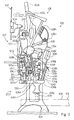
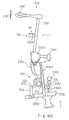
- Fig. 1 is a partially cross sectional side view showing an essential structure of a keyboard musical instrument according to the present invention in an acoustic sound mode;
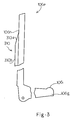
- Fig. 2 is a partially cross sectional side view showing the essential structure of the keyboard musical instrument along a different section;
- Fig. 3 is a side view showing a cam portion formed on a rear surface of a jack;
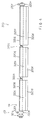
- Fig. 4 is a front view showing a hammer stopper sub-system in a free position;
- Fig. 5 is a front view showing the hammer stopper sub-system in a blocking position;
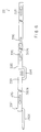
- Fig. 6 is a front view showing a reaction generator in an inactive position;
- Fig. 7 is a front view showing the reaction generator in an active position;
- Figs. 8A and 8B are side views showing a behavior of a key action mechanism and a hammer assembly in a performance through acoustic sounds;
- Figs. 9A and 9B are side views showing a behavior of the key action mechanism, the hammer assembly and an escape accelerator in a performance without an acoustic sound; and
- Fig. 10 is a side view showing another escape accelerator incorporated in a keyboard musical instrument according to the present invention.
- Referring first to figures 1 and 2 of the drawings, a keyboard musical instrument embodying the present invention largely comprises an
acoustic piano 100, anelectronic system 200 and asilent system 300, and has at least an acoustic sound mode for a performance through acoustic sounds and an electronic sound mode for a performance without an acoustic sound. In the following description, word "front" means a position closer to a player than word "rear", and directions "clockwise" and "counter clockwise" are determined on a sheet where a rotating part is illustrated. - The
acoustic piano 100 is an upright piano, and comprises akeyboard 101 provided over akey bed 103. Eighty-eight black andwhite keys keyboard 101, and are turnable around balance pins (not shown). The black andwhite keys white keys white keys white keys white keys white keys - The
upright piano 100 further comprises a plurality of sets ofstrings 104 provided in front of a vertically extending frame (not shown) and stretched between tuning pins (not shown) and hitch pins (not shown). - A
center rail 105a laterally extends in front of thestrings 104, and is shared between all of the sets ofstrings 104. Thecenter rail 105a is positioned over the rear end portions of the black andwhite keys action brackets 105b at both ends and an intermediate point thereof. - The
upright piano 100 further comprises a plurality ofkey action mechanisms 106 functionally connected to the black andwhite keys damper mechanisms 107 actuated by thekey action mechanisms strings 104 and a plurality ofhammer assemblies 108 driven for rotation by thekey action mechanisms 106. When the player depresses one of the black andwhite keys damper mechanism 107 to leave the set ofstrings 104, and actuates thekey action mechanism 106 so as to rotate thehammer assembly 108. Thehammer assembly 108 strikes the set ofstrings 104 in the acoustic sound mode, and the vibratingstrings 104 generate an acoustic sound. When the player releases the key 101a/101b, thekey action mechanism 106 and thehammer assembly 108 return to the initial positions or the home positions, and thedamper mechanism 107 is brought into contact with thestrings 104, thereby absorbing the vibrations of thestrings 104. - The
key action mechanisms 106 are similar in arrangement to one another, and eachkey action mechanism 106 comprises a whippen flange 106a bolted to a lower end portion of thecenter rail 105a and awhippen assembly 106b rotatably connected to the whippen flange 106a. Thewhippen assembly 106b has aheel 106c held in contact with acapstan screw 101c implanted into the rear end portion of the black or white key 101a/101b. - The
key action mechanism 106 further comprises ajack flange 106d upright from a middle portion of thewhippen assembly 106b, ajack 106e turnably supported by thejack flange 106d, ajack spring 106f inserted between thewhippen assembly 106b and atoe 106g of thejack 106e and aregulating button sub-mechanism 106h opposed to thetoe 106g. Thejack 106e has an L-shape, and aswell 106i is formed in the upper portion of thetoe 106g. Thejack spring 106f urges thejack 106e in the counter clockwise direction at all times. - While the black or white key 101a/101b is staying in the rest position, the
whippen assembly 106b is horizontally maintained, and theswell 106i of thetoe 106g is spaced from theregulating button sub-mechanism 106h. Theregulating button sub-mechanism 106h has aregulating button 106j projectable toward and retractable from theswell 106i by turning a regulatingscrew 106k. If the gap between theswell portion 106i and theregulating button 106j is increased, thejack 106e escapes from thehammer assembly 108 later. On the other hand, if the gap is decreased, thejack 106e escapes earlier. - When the
toe 106g is brought into contact with theregulating button 106j, the reaction impedes the motion of the whippen assembly and, accordingly, the depressed key 101a/101b, and the player feels the key 101a/101b heavier than before. Thus, thejack 106e and theregulating button sub-mechanism 106h deeply concern a key-touch, and the position of theregulating button 106j defines the starting point of the escape of thejack 106e. - As shown in figure 3 of the drawings, a
cam member 310 is attached to the rear surface of thejack 106e, and a slope 310a bridges thesurface 106n of thejack 106e and asurface 310b of thecam member 310. As will be described hereinlater, thecam member 310 forms a part of thesilent system 300. - Turning back to figures 1 and 2, the
damper mechanisms 107 are similar in arrangement to one another, and comprises adamper lever flange 107a fixed to an upper surface of thecenter rail 105a, adamper lever 107b rotatably supported by thedamper lever flange 107a, adamper spoon 107c implanted into the rear end portion of thewhippen assembly 106b, a damper wire projecting from thedamper lever 107b, adamper head 107e fixed to thedamper wire 107d and a damper spring (not shown in figure 1) urging thedamper lever 107b in the counter clockwise direction. - While the black or white key 101a/ 101b is staying in the rest position, the
damper spoon 107c does not push thedamper lever 107b, and thedamper head 107e is held in contact with the set ofstrings 104. - When the player depresses the black or white key 101a/101b from the rest position to the end position, the
capstan screw 101c pushes up thewhippen assembly 106b, and thewhippen assembly 106b rotated in the counter clockwise direction causes thedamper spoon 107c to rearwardly push thedamper lever 107b. As a result, thedamper lever 107b is rotated in the clockwise direction, and thedamper head 107e leaves the set ofstrings 104. - On the other hand, when the black or white key 101a/101b is released, the
whippen assembly 106b is rotated in the clockwise direction, and thedamper spoon 107c removes the pressure from thedamper lever 107b. As a result, the damper spring (not shown in figure 1) urges thedamper lever 107b in the counter clockwise direction, and thedamper head 107e is brought into contact with the set ofstrings 104 again. - The
hammer assemblies 108 are also similar in arrangement to one another. Each of thehammer assemblies 108 comprises ahammer butt 108a turnably supported by abutt flange 108b fixed to thecenter rail 105a, ahammer shank 108c upwardly projecting from thehammer butt 108a, ahammer head 108d fixed to the leading end of thehammer shank 108c, acatcher 108e projecting from thehammer butt 108a, aback check 108f implanted into the front end portion of thewhippen assembly 106b, a bridle tape 108g extending between thecatcher 108e, abridle wire 108h implanted into the front end portion of thewhippen assembly 106b and a butt spring 108i urging thehammer butt 108a in the clockwise direction. - While the black or white key 101a/101b is staying in the rest position, the top surface of the
jack 106e is in contact with abutt skin 108j attached to a lower surface of thehammer butt 108a, and thehammer shank 108c is resting on ahammer rail cloth 108k attached to ahammer rail 108m. Thehammer rail 108m is supported through hammer rail hinges 108n by theaction brackets 105b, and the hammer rail hinges 108n are turnably connected to theaction brackets 105b. Though not shown in figures 1 and 2, a soft pedal is connected to the hammer rail hinges 108n, and the angular position of thehammer rail 108m is changed by manipulating the soft pedal. - On the other hand, the depressed key 101a/101b rotates the
whippen assembly 106b and thejack 106e around the whippen flange 106a in the counter clockwise direction, and thejack 106e rotates thehammer assembly 108 in the counter clockwise direction. Theswell portion 106i is brought into contact with theregulating button 106j in the acoustic sound mode. Then, thejack 106e is rotated in the clockwise direction, and escapes from thehammer butt 108a. The jack escaping from thehammer butt 108a kicks thehammer butt 108a, and thehammer assembly 108 is rotated toward the set ofstrings 104. Thehammer head 108d rebounds on thestrings 104 in the acoustic sound mode, and the vibratingstrings 104 generate the acoustic sound. - As described hereinbefore, when the
swell portion 106i is brought into contact with theregulating button 106j, thejack 106e starts the escape. The escape is completed upon release of thehammer butt 108a from thejack 106e. When thejack 106e starts the escape, the friction between the top surface of thejack 106e and thebutt skin 108 and the elastic force of thejack spring 106f, the player feels the depressed key heavier. When thehammer butt 108 is released, the player feels the key 101a/101b lighter, and the change of the load from the rest position to the end position is called as "key touch". The change of the load from the starting point of the escape to the completing point of the escape is called as "after touch", and strongly impresses the key touch on the player. - On the other hand, after the strike of the strings, the hammer assembly is rotated in the clockwise direction. When the key 101a/101b reaches the end position, the
catcher 108e is brought into contact with theback check 108f. At this time, the motion of the key/key action mechanism is temporarily stopped. Thereafter, the player leaves the finger from the key, and all the components return to the initial positions. Even though thecatcher 108e rebounds, the bridle tape 108g links thewhippen assembly 106b with thehammer assembly 108, and prevents the set ofstrings 104 from a double strike. Moreover, while the player is repeating the key, the bridle tape 108g accelerates the returning motion of the hammer assembly. Thejack spring 106f urges thejack 106e so as to come into contact with thebutt skin 108j again. - The
key action mechanisms 106, thedamper mechanisms 107 and thehammer assemblies 108 are similar to those of a standard upright piano. - The
electronic system 200 comprises a plurality ofkey sensors 210 respectively provided under the black andwhite keys unit 220 responsive to the key position signals KP for generating an audio signal AD and aheadphone 230 for generating electronic sounds. Thekey sensors 210 and the controllingunit 220 are similar to those disclosed in U.S.P. 2,250,065, and no further description is incorporated hereinbelow for the sake of simplicity. - The
silent system 300 largely comprises ahammer stopper sub-system 320 and anescape accelerating sub-system 330, and thehammer stopper sub-system 320 is linked with the escape accelerating sub-system by means of alink sub-system 340 in this instance. - Figures 4 and 5 illustrate the
hammer stopper sub-system 320 in detail. Thehammer stopper sub-system 320 includes ashaft member 320a rotatably supported by bearingunits 320b (see figure 1) bolted to theaction brackets 105b. Theshaft member 320a horizontally extends in the lateral direction of theacoustic piano 100 between thestrings 104 and thehammer shanks 108c at the home position. - The
hammer stopper sub-system 320 further includescushion brackets 320c attached to theshaft member 320a at intervals andcushion members 320d respectively fixed to thecushion brackets 320c. Thecushion brackets 320c are associated with the strings for high-pitch tones, the strings for middle-pitch tones and the strings for low-pitch tones so that the bearingunits 320b rotatably support theshaft member 320a at theaction brackets 105b. - The
hammer stopper sub-system 320 further includes a change-overmechanism 321 manipulative by the player for angularly moving theshaft member 320a, and the change-overmechanism 321 changes thehammer stopper sub-mechanism 320 between a free position and a blocking position. In detail, the change-overmechanism 321 has alever 321a fixed to theshaft member 320a, a spring member 321b (see figure 1) urging theshaft member 320a in the clockwise direction, aflexible wire 321c engaged at one end thereof to thelever 321a and a nob 321d slidably supported by abracket 321e fixed to thekey bed 103 and connected to the other end of theflexible wire 321c. - While no pulling force is exerted on the nob 321d, the spring 321b urges the
shaft member 320a so as to direct thecushion members 320d downwardly as shown in figure 4, and thehammer stopper sub-system 320 allows the hammer heads 108d to strike the sets ofstrings 104 without an interruption with thecushion members 320d. The position allowing the hammer heads 108d to strike thestrings 104 is referred to "free position FP". - On the other hand, if the nob 321d is pulled, the
flexible wire 321c rotates thelever 321a, and, accordingly, theshaft member 320a is rotated in the counter clock-wise direction against the elastic force of the spring 321b, and thecushion members 320d are opposed to thehammer shanks 108c. The position thus opposed to thehammer shanks 108c is referred to "blocking position BP". - If the player depresses the key 101a/101b, the
jack 106e of thekey action mechanism 106 rotates thehammer butt 108a, and, thereafter, thejack 106e escapes from thehammer butt 108a. Thehammer assemblies 108 rushes toward thestrings 104. However, thehammer shanks 108c rebound on thecushion members 320d in the blocking position BP before an impact on thestrings 104, and the set ofstrings 104 does not generate an acoustic sound. - The
jack 106e completes the escape from thehammer butt 108a at 6 to 8 millimeters between thehammer head 108d and thestrings 104, and thehammer shank 108c rebounds on thecushion member 320d after thejack 106e completes the escape from thehammer butt 108a. - The
hammer stopper sub-system 320 further includesstopper rings 320e fixed to theshaft member 320a by means ofpins 320f andprotective sheets 320g attached to the opposite surfaces of thecushion brackets 320c. Thestopper rings 320e set limits on the axial motion of theshaft member 320a, and theshaft member 320a can not axially move over thestopper ring 320e. Theprotective sheets 320g is formed of artificial leather, cloth or felt, and take up impact of thedamper wires 107d. - The
escape accelerating sub-system 330 largely comprises thecam members 310 respectively attached to thejacks 106e and areaction generator 331, and is changed between an active position and an inactive position. While theescape accelerating sub-system 330 is staying in the active position, thecam member 310 cooperates with thereaction generator 331 so as to convert a part of the force exerted on thewhippen assembly 106b into a force exerted on thejack 106e for rotating it around thejack flange 106d. - The
reaction generator 331 includes ashaft member 332 split into twoparts cushion sheets 333 respectively wrapping the twoparts rod member 334 connecting the twoparts rod member 334 is bent twice, and is shaped into a U-configuration. Therefore, the connectingrod member 334 forms agap 335 between the twoparts gap 335 allows theaction bracket 105b provided at an intermediate portion of thecenter rail 105a to be without an interference with thereaction generator 331. - The
reaction generator 331 further includes a plurality ofrod members 336 fixed to theshaft member 332 at intervals and a plurality of bearingunits 337 attached to thecenter rail 105a. Therod members 336 has a straight portions extending in parallel to theshaft member 332, and the straight portions of therod members 336 are turnably supported by the bearingunits 337. For this reason, theshaft member 332 is angularly movable around the bearingunits 337, and thecushion sheets 333 becomes closer to or spaced from the rear surface of thejacks 106e. - The
reaction generator 331 is linked with thehammer stopper sub-system 320 by means of thelink sub-system 340 as described hereinbefore. Thelink sub-system 340 includes a bracket member 340a fixed to thecenter rail 105a, an inverted L-shapedarm member 340b turnably supported by the bracket member 340a, a connecting rod 340c inserted into a slot formed in one end portion of the inverted L-shapedarm member 340b and an adjusting mechanism 340d provided between the other end portion of the inverted L-shapedarm member 340b and thelever 321a. - When the spring member 321b urges the
lever 321a in the clockwise direction, the elastic force of the spring member 321b is transferred through the adjusting mechanism 340d to the inverted L-shapedarm member 340b, and the inverted L-shapedarm member 340b is rotated in the clockwise direction around the bracket 340a. As a result, thecushion sheets 333 is spaced from the rear surfaces of thejacks 106e, and thereaction generator 330 remains in the inactive position. - On the other hand, if the nob 321d is pulled, the
flexible wire 321c rotates thelever 321a in the counter clockwise direction, and the rotation of thelever 321a is transferred through the adjusting mechanism 340d to the inverted L-shapedarm member 340b. As a result, the inverted L-shapedarm member 340b is rotated in the counter clockwise direction, and theshaft member 332 and thecushion sheets 333 become closer to the rear surfaces of thejacks 106e. As a result, thereaction generator 330 causes theescape accelerating sub-system 330 to enter into the active position. - The adjusting mechanism 340d includes connecting
bolt members arm member 340b and thelever 321a and a bracket member 340g formed with female threaded portions engaged with the connectingbolt members bolt members lever 321a and the inverted L-shapedarm member 340b is decreased. This means that thecushion sheets 333 become slightly spaced from the rear surfaces of thejacks 106e. On the other hand, if the bracket member 340g turns in the opposite direction, the gap is increased, and thecushion sheets 333 are slightly closer to the rear surfaces of thejacks 106e. Thus, the adjusting mechanism 340d appropriately regulates thereaction generator 331 at the active position. - Description is hereinbelow made on behaviors of the keyboard musical instrument in the acoustic sound mode and the silent mode.
- First, a player is assumed to perform a music through the acoustic sounds. The player does not manipulate the nob 321d, and the spring 321b pulls down the
lever 321a. As a result, thehammer stopper sub-system 320 and theescape accelerating sub-system 330 remain in the free position FP and the inactive position, respectively, and the keyboard musical instrument is in the acoustic sound mode. Figures 8A and 8B illustrate thekey action mechanism 106 and thehammer assembly 108 in the acoustic sound mode. - When the player depresses the white key 101b in the performance, the
capstan button 101c pushes up thewhippen assembly 106b, and thewhippen assembly 106b and thejack 106e is rotated around the whippen flange 106a in the counter clockwise direction. Thejack 106e is not rotated around thejack flange 106d until theswell portion 106i is brought into contact with theregulating button 106j. As a result, thejack 106e rotates thehammer assembly 108 in the counter clockwise direction. - When the
swell portion 106i is brought into contact with theregulating button 106j as shown in figure 8A, the rotation of thewhippen assembly 106b causes thejack 106e to rotate in the clockwise direction around thejack flange 106d against thejack spring 106f, and thejack 106e escapes from thehammer butt 108a. Thus, thejack 106e starts the escape at the contact with theregulating button 106j, and completes the escape from thehammer butt 108a. At this time, theescape accelerating sub-system 330 in the inactive position does not affect the motion of thejack 106e. - After the
jack 106e escapes from thehammer butt 108a, thehammer head 108d rushes toward the set ofstrings 104. However, thehammer stopper sub-system 320 in the free position FP does not interrupts the hammer action. In other words, thehammer head 108d strikes thestrings 104. In this instance, when the hammer reaches apoint 2 to 3 millimeters spaced from thestrings 104 by softly depressing the key not to strike thestrings 104, the escape is completed. - The
hammer head 108d rebounds on the set of strings 104 (as shown in figure 8B), and returns to the home position on thehammer rail cloth 108k. The set ofstrings 104 vibrates, and generates the acoustic sound. - On the other hand, when the player wants to perform a music without an acoustic sound, the player pulls the nob 321d, and the
flexible wire 321c rotates thelever 321a in the counter clockwise direction, and thehammer stopper sub-system 320 enters into the blocking position BP. Thelink sub-system 340 transfers the rotation of thelever 321a to the reaction generator 3310, and theescape accelerating sub-system 330 enters into the active position. Thus, the keyboard musical instrument enters into the silent mode. Figures 9A and 9B illustrate thekey action mechanism 106 and thehammer assembly 108 in the silent mode. - Assuming now that the player depresses the white key 101b in the silent mode, the
capstan button 101c pushes up thewhippen assembly 106b, and thewhippen assembly 106b and thejack 106e is rotated around the whippen flange 106a in the counter clockwise direction. Therear surface 106n of thejack 106e is brought into contact with thecushion sheet 333 of thereaction generator 331 before the contact between theswell portion 106i and theregulating button 106j as shown in figure 9A. However, thejack 106e does not start the rotation around thejack flange 106d. - After the contact with the
reaction generator 331, thecapstan button 101c is upwardly pushing thewhippen assembly 106b and thejack 106e, and the contact point with thereaction generator 331 is moved along the slope 310a (see figure 3) of thecam member 310. While thereaction generator 331 is sliding on the slope 310a, a part of the force for the rotation of thewhippen assembly 106b is converted to a force exerted on thejack 106e for rotating in the clockwise direction. As a result, thejack 106e rapidly escapes from thehammer butt 108a, and the escape of thejack 106e is completed at an earlier position where thehammer head 108d reaches 6 to 8 millimeters from thestrings 104. - The sliding motion along the slope 310a exerts a load against the white key 101b. However, the load is approximately equal to that in the acoustic performance. Even though the
jack 106e completes the escape earlier than the escape in the acoustic sound mode, the load is exerted to a finger of the player at the contact with thereaction generator 331 substantially concurrent to the contact between theswell portion 106i and theregulating button sub-system 106j, and the player feels the key touch unchanged. - After the escape, the hammer heads 108 rushes toward the set of
strings 104 as shown in figure 9B, and thehammer shank 108c rebounds on thecushion member 320d before a strike at thestrings 104. Thus, thehammer stopper sub-system 320 prevents the set ofstrings 104 from the strike of thehammer head 108d, and the set ofstrings 104 do not vibrate. - The escape of the
jack 106e in the silent mode is completed earlier than the escape in the acoustic sound mode, and, for this reason, thehammer shank 108 does not get between thejack 106e and thecushion member 320d. - After the rebound on the
cushion member 320d, thehammer assembly 108 returns to the home position. - As will be appreciate from the foregoing description, although the
escape accelerating sub-system 330 according to the present invention causes thejack 106e to complete the escape from thehammer butt 108a earlier than theregulating button 106j, the change of the load exerted to the key 101a/101b moving from the rest position to the end position is substantially same as theregulating button 106j. For this reason, the player feels the key touch unchanged between the acoustic sound mode and the silent mode without a capture of thehammer shank 108c between thejack 106e and thehammer stopper sub-system 320. - Moreover, the
regulating button mechanism 106h is adjustable independently from the adjustment work on thereaction generator 331, and the assembling work and the adjusting work/ the tuning work are easier than the keyboard musical instrument disclosed in Japanese Utility Model Application No. 5-38463. - The
escape accelerating sub-system 330 according to the present invention is simpler than the spacers insertable beneath the regulating buttons in the silent mode and disclosed in Japanese Utility Model Application No. 5-56462, and thereaction generator 331 is less affectable by an aged deterioration rather than the spacers. - Figure 10 illustrates essential parts of another keyboard musical instrument embodying the present invention. The keyboard musical instrument implementing the second embodiment also largely comprises an
acoustic piano 500, an electronic system (not shown) and asilent system 600. Theacoustic piano 500 is similar to theacoustic piano 100, and component parts of theacoustic piano 500 are labeled with the same references as those of theacoustic piano 100 without detailed description. - The
silent system 600 includes ahammer stopper sub-system 610, anescape accelerating sub-system 620 and alink mechanism 630, and thehammer stopper sub-system 610 and thelink mechanism 630 are similar to those of the first embodiment. For this reason, description is focused on theescape accelerating sub-system 620 only for the sake of simplicity. - The
escape accelerating sub-system 620 is implemented by areaction generator 621 only. As to thereaction generator 621, the contact point with the jack in the active position is limited, and a cum is not provided on thejack 106e. In other words, thereaction generator 621 is similar to thereaction generator 310 except for thecum 310 and the contact point with thejack 106e. In detail, thejack 106e is turnable around thejack flange 106d, and apin 501 provides a center of the turning motion. Thereaction generator 621 is arranged in such a manner that the distance between thepin 501 and a contact point with therear surface 106n is shorter than the distance between thepin 501 and theswell portion 106i. In this instance, thereaction generator 621 serves as a reaction generating means. - In the silent mode, the
jack 106e is brought into contact with thereaction generator 621 at thepoint 502, and thepoint 502 provides a reaction point to the turning motion of thejack 106e. Since the distance between thepin 501 and thepoint 502 is shorter than the distance between thepin 501 and theswell portion 106i, the angular velocity at theleading end 503 of thejack 106e is larger than the angular velocity in the acoustic sound mode, and thejack 106e completes the escape in the silent mode earlier than the escape in the acoustic sound mode. - The
rear surface 106n of thejack 106e is brought into contact with thereaction generator 621 substantially in concurrence with the contact between theswell portion 106i and theregulating button 106j, and, for this reason, the player feels the key touch unchanged. However, thejack 106e completes the escape in the silent mode earlier than the escape in the acoustic sound mode, and thehammer shank 108c never get between thejack 106e and thehammer stopper 610. - The
escape accelerating sub-system 620 is simpler than theescape accelerating sub-system 330, and achieves all the advantages over the prior arts. - Although particular embodiments of the present invention have been shown and described, it will be obvious to those skilled in the art that various changes and modifications may be made without departing from the spirit and scope of the present invention.
- For example, the upright piano may be replaced with another keyboard musical instrument such as, for example, a grand piano, a harpsichord or a celesta. If a grand piano is used, the term "hammer butt" is read as "hammer roller", then the description is applicable to the keyboard musical instrument having the grand piano.
- The keyboard musical instrument according to the present invention may be equipped with an automatic playing system for reproducing a performance by selectively actuating the keys. In this instance, the keyboard musical instrument according to the present invention further has a playback mode and/or a recording mode.
- The
hammer stopper 320 and thereaction generator 330 may be changed by means of an electric motor unit or a solenoid-operated actuator, and may be respectively associated with change-over means for independently changing the positions. - Finally, the hammer stopper sub-system may have a plurality of cushion peaces moved in a lateral direction by a half of the pitch between the adjacent hammer shanks. In this instance, if the cushion peaces are opposed to the hammer shanks in the silent mode, the hammer shanks rebound on the cushion peaces. However, if the cushion peaces are moved by the half pitch, the hammer shanks pass the gaps between the cushion peaces.
- It should be noted that the objects and advantages of the invention may be attained by means of any compatible combination(s) particularly pointed out in the items of the following summary of the invention and the appended claims.
-
- 1. A keyboard musical instrument having at least an acoustic sound mode for a performance through acoustic sounds and a silent mode for a performance without an acoustic sound, comprising:
an acoustic keyboard instrument (100; 500) including
a keyboard (101) having a plurality of keys (101a/101b) respectively assigned notes of a scale and selectively depressed by a player in both of said acoustic sound mode and said silent mode,
a plurality of key action mechanisms (106) functionally connected to said plurality of keys (101a/101b), respectively, and having respective jacks (106e) and a regulating sub-mechanism (106h) associated with said jacks (106e), said jacks being brought into contact with said regulating sub-mechanism (106h) so as to start escapes when said plurality of keys (101a/101b) are depressed by said player in said acoustic sound mode,
a plurality of hammer assemblies (108) respectively associated with said plurality of key action mechanisms (106) and respectively driven for rotation through said escapes of said jacks (106e) by said plurality of key action mechanisms (106) when said player selectively depresses said plurality of keys (101a/101b), and
a plurality of string means (104) respectively assigned said notes and respectively struck by said plurality of hammer assemblies (108) for producing acoustic sounds in said acoustic sound mode; and
a silent system (300; 600) including
a hammer stopper (320; 610) changed between a free position (FP) in said acoustic sound mode and a blocking position (BP) in said silent mode, said plurality of hammer assemblies (108) being allowed to strike said plurality of string means (104) without an interruption of said hammer stopper in said free position (FP), said plurality of hammer assemblies (108) rebounding on said hammer stopper (320; 610) in said blocking position (BP) before a strike at said string means (104),
characterized in that
said silent system (300; 600) further includes
an escape accelerator (330; 620) associated in said plurality of key action mechanisms (106) and causing said jacks (106e) to complete said escapes in said silent mode earlier than said acoustic sound mode. - 2, The keyboard musical instrument
further comprising
an electronic system (200) responsive to key motions of the keys depressed by said player in said silent mode for generating electronic sounds having the notes of said scale corresponding to said keys depressed by said player. - 3. The keyboard musical instrument
in which said escape accelerator (330; 620) starts an acceleration of said escape at said starting point. - 4. The keyboard musical instrument
in which said escape accelerator (330) includes
a reaction generator (331) changed between an inactive position in said acoustic sound mode and an active position in said silent mode, and
cam members (310) respectively attached to surfaces (106n) of said jacks (106e) and engaged with said reaction generator (331) maintained in said active position when said plurality of keys (101a/101b) depressed by said player move said plurality of key action mechanisms (106), each of said cam members (310) engaged with said reaction generator (331) forcing the associated jack (106e) to complete the escape in said silent mode earlier than the escape in said acoustic sound mode. - 5. The keyboard musical instrument
in which each of said cam members (310) has a first surface (310b) spaced from the surface (106n) of the associated jack (106e) and a second surface (310a) connecting said surface (106n) of said associated jack (106e) to said first surface (310b), an engaging point with said reaction generator (331) being moved from said surface (106n) of said associated jack (106e), said second surface (310a) and said first surface (310b) so as to force said associated jack (106e) to escape from the associated hammer assembly (108). - 6. The keyboard musical instrument
in which the surface (106n) of said associated jack (106e) is engaged with said reaction generator (331) substantially in concurrence with said contact between said jack (106e) and said regulating button sub-mechanism (106h). - 7. The keyboard musical instrument
further comprising
an electronic system (200) responsive to key motions of the keys depressed by said player in said silent mode for generating electronic sounds having the notes of said scale corresponding to said keys depressed by said player. - 8. The keyboard musical instrument
in which said silent system (300) further includes a link mechanism (340) connecting said hammer stopper (320) to said reaction generator (331) so as to synchronize a change between said free position (FP) and said blocking position (BP) with a change between said inactive position and said active position. - 9. The keyboard musical instrument
in which said link mechanism (340) has an adjusting sub-mechanism (340e/340f/340g) for regulating said active position of said reaction generator with respect to said jacks (106e). - 10. The keyboard musical instrument
in which said escape accelerator (620) includes
a reaction generating means (621) changed between an inactive position in said acoustic sound mode and an active position in said silent mode, each of said jacks (106e) being engaged with said reaction generating means (621) maintained in said active position so as to be forced to escape from the hammer assembly (108), a distance between a turnably supporting point (501) of said each of said jacks (106e) and an engaging point (502) with said reaction generating means (621) being shorter than a distance between said turnably supporting point (501) and the contact point (106i) with said regulating button sub-mechanism (106h). - 11. The keyboard musical instrument
in which said silent system (600) further includes a link mechanism (630) connecting said hammer stopper (610) to said reaction generating means (621) so as to synchronize a change between said free position and said blocking position with a change between said inactive position and said active position. - 12. The keyboard musical instrument
in which said link mechanism (630) has an adjusting sub-mechanism (340e/340f/340g) for regulating said active position of said reaction generating means (621) with respect to said jacks (106e). - 13. The keyboard musical instrument
further comprising
an electronic system responsive to key motions of the keys depressed by said player in said silent mode for generating electronic sounds having the notes of said scale corresponding to said keys depressed by said player.
Claims (10)
- A keyboard musical instrument having at least an acoustic sound mode for a performance through acoustic sounds and a silent mode for a performance without an acoustic sound, comprising:
an acoustic keyboard instrument (100; 500) including
a keyboard (101) having a plurality of keys (101a/101b) respectively assigned notes of a scale and selectively depressed by a player in both of said acoustic sound mode and said silent mode,
a plurality of key action mechanisms (106) functionally connected to said plurality of keys (101a/101b), respectively, and having respective jacks (106e) and a regulating sub-mechanism (106h) associated with said jacks (106e), said jacks being brought into contact with said regulating sub-mechanism (106h) so as to start escapes when said plurality of keys (101a/101b) are depressed by said player in said acoustic sound mode,
a plurality of hammer assemblies (108) respectively associated with said plurality of key action mechanisms (106) and respectively driven for rotation through said escapes of said jacks (106e) by said plurality of key action mechanisms (106) when said player selectively depresses said plurality of keys (101a/101b), and
a plurality of string means (104) respectively assigned said notes and respectively struck by said plurality of hammer assemblies (108) for producing acoustic sounds in said acoustic sound mode; and
a silent system (300; 600) including
a hammer stopper (320; 610) changed between a free position (FP) in said acoustic sound mode and a blocking position (BP) in said silent mode, said plurality of hammer assemblies (108) being allowed to strike said plurality of string means (104) without an interruption of said hammer stopper in said free position (FP), said plurality of hammer assemblies (108) rebounding on said hammer stopper (320; 610) in said blocking position (BP) before a strike at said string means (104),
characterized in that
said silent system (300; 600) further includes
an escape accelerator (330; 620) associated in said plurality of key action mechanisms (106) and causing said jacks (106e) to complete said escapes in said silent mode earlier than said acoustic sound mode. - The keyboard musical instrument as set forth in claim 1, further comprising
an electronic system (200) responsive to key motions of the keys depressed by said player in said silent mode for generating electronic sounds having the notes of said scale corresponding to said keys depressed by said player, wherein preferably
said escape accelerator (330; 620) starts an acceleration of said escape at said starting point. - The keyboard musical instrument as set forth in claim 1, in which said escape accelerator (330) includes
a reaction generator (331) changed between an inactive position in said acoustic sound mode and an active position in said silent mode, and
cam members (310) respectively attached to surfaces (106n) of said jacks (106e) and engaged with said reaction generator (331) maintained in said active position when said plurality of keys (101a/101b) depressed by said player move said plurality of key action mechanisms (106), each of said cam members (310) engaged with said reaction generator (331) forcing the associated jack (106e) to complete the escape in said silent mode earlier than the escape in said acoustic sound mode. - The keyboard musical instrument as set forth in claim 3, in which each of said cam members (310) has a first surface (310b) spaced from the surface (106n) of the associated jack (106e) and a second surface (310a) connecting said surface (106n) of said associated jack (106e) to said first surface (310b), an engaging point with said reaction generator (331) being moved from said surface (106n) of said associated jack (106e), said second surface (310a) and said first surface (310b) so as to force said associated jack (106e) to escape from the associated hammer assembly (108).
- The keyboard musical instrument as set forth in claim 4, in which the surface (106n) of said associated jack (106e) is engaged with said reaction generator (331) substantially in concurrence with said contact between said jack (106e) and said regulating button sub-mechanism (106h), and preferably
comprising
an electronic system (200) responsive to key motions of the keys depressed by said player in said silent mode for generating electronic sounds having the notes of said scale corresponding to said keys depressed by said player. - The keyboard musical instrument as set forth in claim 3, in which said silent system (300) further includes a link mechanism (340) connecting said hammer stopper (320) to said reaction generator (331) so as to synchronize a change between said free position (FP) and said blocking position (BP) with a change between said inactive position and said active position, wherein preferably
said link mechanism (340) has an adjusting sub-mechanism (340e/340f/340g) for regulating said active position of said reaction generator with respect to said jacks (106e). - The keyboard musical instrument as set forth in claim 1, in which said escape accelerator (620) includes
a reaction generating means (621) changed between an inactive position in said acoustic sound mode and an active position in said silent mode, each of said jacks (106e) being engaged with said reaction generating means (621) maintained in said active position so as to be forced to escape from the hammer assembly (108), a distance between a turnably supporting point (501) of said each of said jacks (106e) and an engaging point (502) with said reaction generating means (621) being shorter than a distance between said turnably supporting point (501) and the contact point (106i) with said regulating button sub-mechanism (106h), wherein preferably
said silent system (600) further includes a link mechanism (630) connecting said hammer stopper (610) to said reaction generating means (621) so as to synchronise a change between said free position and said blocking position with a change between said inactive position and said active position. - The keyboard musical instrument as set forth in claim 7, in which said link mechanism (630) has an adjusting sub-mechanism (340e/340f/340g) for regulating said active position of said reaction generating means (621) with respect to said jacks (106e).
- The keyboard musical instrument as set forth in claim 7, further comprising
an electronic system responsive to key motions of the keys depressed by said player in said silent mode for generating electronic sounds having the notes of said scale corresponding to said keys depressed by said player. - A keyboard musical instrument having at least an acoustic sound mode for a performance through acoustic sounds and a silent mode for a performance without an acoustic sound, comprising:
an acoustic keyboard instrument (100; 500) including
a keyboard (101) (101a/101b) respectively assigned notes of a scale and selectively depressed by a player in both of said acoustic
a plurality of key action mechanisms (106) having respective jacks (106e)
a plurality of hammer assemblies (108) and
a plurality of string means (104) ; and
a silent system (300; 600) including
a hammer stopper (320; 610)
characterized in that
said silent system (300; 600) further includes
an escape accelerator (330; 620) associated in said plurality of key action mechanisms (106) and causing said jacks (106e) to complete said escapes in said silent mode earlier than said acoustic sound mode.
Applications Claiming Priority (3)
| Application Number | Priority Date | Filing Date | Title |
|---|---|---|---|
| JP13026794 | 1994-06-13 | ||
| JP6130267A JPH07334150A (en) | 1994-06-13 | 1994-06-13 | Keyboard instrument |
| JP130267/94 | 1994-06-13 |
Publications (3)
| Publication Number | Publication Date |
|---|---|
| EP0689182A2 true EP0689182A2 (en) | 1995-12-27 |
| EP0689182A3 EP0689182A3 (en) | 1999-01-07 |
| EP0689182B1 EP0689182B1 (en) | 2003-08-27 |
Family
ID=15030205
Family Applications (1)
| Application Number | Title | Priority Date | Filing Date |
|---|---|---|---|
| EP95109061A Expired - Lifetime EP0689182B1 (en) | 1994-06-13 | 1995-06-12 | Keyboard musical instrument having jacks changeable in escape speed between acoustic sound mode and silent mode |
Country Status (6)
| Country | Link |
|---|---|
| US (1) | US5583306A (en) |
| EP (1) | EP0689182B1 (en) |
| JP (1) | JPH07334150A (en) |
| KR (1) | KR0185258B1 (en) |
| DE (1) | DE69531570T2 (en) |
| TW (1) | TW298643B (en) |
Cited By (2)
| Publication number | Priority date | Publication date | Assignee | Title |
|---|---|---|---|---|
| WO1997005599A1 (en) * | 1995-07-26 | 1997-02-13 | Asm Advanced Systems Musical Services Gmbh | Device for acoustically silencing a mechanically-operated keyboard instrument |
| ITVE20100028A1 (en) * | 2010-06-11 | 2011-12-12 | Paolo Pancino | VERTICAL PIANO, AND IN PARTICULAR THE MECHANICS OF TALE PIANO |
Families Citing this family (14)
| Publication number | Priority date | Publication date | Assignee | Title |
|---|---|---|---|---|
| JP3900706B2 (en) * | 1998-09-07 | 2007-04-04 | ヤマハ株式会社 | Keyboard device |
| JP3292164B2 (en) * | 1999-01-22 | 2002-06-17 | ヤマハ株式会社 | Keyboard instrument silencer |
| JP3873522B2 (en) * | 1999-05-06 | 2007-01-24 | ヤマハ株式会社 | Silencer for keyboard instruments |
| JP3598942B2 (en) * | 2000-05-01 | 2004-12-08 | ヤマハ株式会社 | Piano damper mechanism |
| JP4923328B2 (en) * | 2001-03-01 | 2012-04-25 | ヤマハ株式会社 | Escape adjustment device for keyboard instrument and volume control device for keyboard instrument |
| JP4741956B2 (en) * | 2006-02-14 | 2011-08-10 | 株式会社河合楽器製作所 | Hammer rail device for upright piano |
| JP5020522B2 (en) * | 2006-03-08 | 2012-09-05 | 株式会社河合楽器製作所 | Upright piano jack stationary |
| WO2009108437A1 (en) | 2008-02-27 | 2009-09-03 | Steinway Musical Instruments, Inc. | Pianos playable in acoustic and silent modes |
| US8541673B2 (en) | 2009-04-24 | 2013-09-24 | Steinway Musical Instruments, Inc. | Hammer stoppers for pianos having acoustic and silent modes |
| US8148620B2 (en) * | 2009-04-24 | 2012-04-03 | Steinway Musical Instruments, Inc. | Hammer stoppers and use thereof in pianos playable in acoustic and silent modes |
| JP5229359B2 (en) * | 2011-07-19 | 2013-07-03 | ヤマハ株式会社 | Escape adjustment device and volume control device for keyboard instrument |
| WO2016200483A1 (en) * | 2015-06-12 | 2016-12-15 | Steinway, Inc. | Piano extended soft pedal |
| AT523227B1 (en) * | 2019-11-26 | 2023-03-15 | PIANO | |
| KR102343343B1 (en) | 2021-01-02 | 2021-12-28 | 주식회사 거여바이오텍 | Drying system for waste sludge that combines optimal drying rate and mass treatment capacity |
Citations (21)
| Publication number | Priority date | Publication date | Assignee | Title |
|---|---|---|---|---|
| DE44782C (en) | J. P. DEVIGNEE, Professor der Musik in Verviers, Belgien; [ | Device for changing the strength of the hammer stroke on pianinos | ||
| DE97885C (en) | ||||
| DE68406C (en) | O. THEIN in Bremen, Meinkenstrafse 50 | Connection of a pianino with a harmonium | ||
| US2250065A (en) | 1940-12-07 | 1941-07-22 | James A Kochl | Musical instrument |
| JPS5167732A (en) | 1974-12-05 | 1976-06-11 | Dainippon Jochugiku Kk | KUKANEAZOOR USATSUCHUZAI |
| CH614303A5 (en) | 1977-02-18 | 1979-11-15 | Martin Von Allmen | Electronic tone-generating device for installation into a piano, and piano having the tone-generating device |
| JPS5555880A (en) | 1978-10-18 | 1980-04-24 | Canon Inc | Thermal printer |
| US4633753A (en) | 1984-05-15 | 1987-01-06 | Nippon Gakki Seizo Kabushiki Kaisha | Muffler mechanism for a piano |
| JPS6232308A (en) | 1985-08-03 | 1987-02-12 | Fuji Photo Film Co Ltd | Position detector |
| US4704931A (en) | 1985-06-17 | 1987-11-10 | Nippon Gakki Seizo Kabushiki Kaisha | Acoustic tone inhibiting means for keyboard musical instrument |
| JPS6397997A (en) | 1986-10-15 | 1988-04-28 | ヤマハ株式会社 | Damper for piano |
| US4744281A (en) | 1986-03-29 | 1988-05-17 | Yamaha Corporation | Automatic sound player system having acoustic and electronic sound sources |
| DE3707591C1 (en) | 1987-03-10 | 1988-05-26 | Seiler Ed Pianofortefab Gmbh | Grand piano or piano |
| US4970929A (en) | 1989-03-13 | 1990-11-20 | Kawai Gakki Seisakusho Co., Ltd. | Muffler for pianos |
| US5115705A (en) | 1989-02-16 | 1992-05-26 | Charles Monte | Modular electronic keyboard with improved signal generation |
| JPH04174813A (en) | 1990-11-08 | 1992-06-23 | Fuji Photo Optical Co Ltd | Zoom lens |
| JPH0538463A (en) | 1991-08-06 | 1993-02-19 | Kyokuto Kaihatsu Kogyo Co Ltd | Crushing method for synthetic resin-made tank and crusher to be used |
| JPH0556462U (en) | 1991-12-24 | 1993-07-27 | ダイニック株式会社 | Binding materials and binding materials |
| US5247129A (en) | 1991-06-10 | 1993-09-21 | Yamaha Corporation | Stringless piano-touch electric sound producer for directly driving a sound board on the basis of key actions |
| US5374775A (en) | 1992-06-09 | 1994-12-20 | Yamaha Corporation | Keyboard instrument for selectively producing mechanical sounds and synthetic sounds without any mechanical vibrations on music wires |
| US7309293B2 (en) | 2006-02-06 | 2007-12-18 | Beatrice Dunks | Golf ball gripping device |
Family Cites Families (2)
| Publication number | Priority date | Publication date | Assignee | Title |
|---|---|---|---|---|
| DE1259185B (en) * | 1965-11-30 | 1968-01-18 | Malmsjoe Piano Ab | Device for the mechanical transmission of the impulses triggered on a keyboard to the strings of a piano |
| JP3430638B2 (en) * | 1994-03-31 | 2003-07-28 | ヤマハ株式会社 | Keyboard instrument |
-
1994
- 1994-06-13 JP JP6130267A patent/JPH07334150A/en active Pending
-
1995
- 1995-06-05 US US08/464,045 patent/US5583306A/en not_active Expired - Fee Related
- 1995-06-09 TW TW084105867A patent/TW298643B/zh active
- 1995-06-12 DE DE69531570T patent/DE69531570T2/en not_active Expired - Lifetime
- 1995-06-12 EP EP95109061A patent/EP0689182B1/en not_active Expired - Lifetime
- 1995-06-13 KR KR1019950015567A patent/KR0185258B1/en not_active IP Right Cessation
Patent Citations (21)
| Publication number | Priority date | Publication date | Assignee | Title |
|---|---|---|---|---|
| DE97885C (en) | ||||
| DE68406C (en) | O. THEIN in Bremen, Meinkenstrafse 50 | Connection of a pianino with a harmonium | ||
| DE44782C (en) | J. P. DEVIGNEE, Professor der Musik in Verviers, Belgien; [ | Device for changing the strength of the hammer stroke on pianinos | ||
| US2250065A (en) | 1940-12-07 | 1941-07-22 | James A Kochl | Musical instrument |
| JPS5167732A (en) | 1974-12-05 | 1976-06-11 | Dainippon Jochugiku Kk | KUKANEAZOOR USATSUCHUZAI |
| CH614303A5 (en) | 1977-02-18 | 1979-11-15 | Martin Von Allmen | Electronic tone-generating device for installation into a piano, and piano having the tone-generating device |
| JPS5555880A (en) | 1978-10-18 | 1980-04-24 | Canon Inc | Thermal printer |
| US4633753A (en) | 1984-05-15 | 1987-01-06 | Nippon Gakki Seizo Kabushiki Kaisha | Muffler mechanism for a piano |
| US4704931A (en) | 1985-06-17 | 1987-11-10 | Nippon Gakki Seizo Kabushiki Kaisha | Acoustic tone inhibiting means for keyboard musical instrument |
| JPS6232308A (en) | 1985-08-03 | 1987-02-12 | Fuji Photo Film Co Ltd | Position detector |
| US4744281A (en) | 1986-03-29 | 1988-05-17 | Yamaha Corporation | Automatic sound player system having acoustic and electronic sound sources |
| JPS6397997A (en) | 1986-10-15 | 1988-04-28 | ヤマハ株式会社 | Damper for piano |
| DE3707591C1 (en) | 1987-03-10 | 1988-05-26 | Seiler Ed Pianofortefab Gmbh | Grand piano or piano |
| US5115705A (en) | 1989-02-16 | 1992-05-26 | Charles Monte | Modular electronic keyboard with improved signal generation |
| US4970929A (en) | 1989-03-13 | 1990-11-20 | Kawai Gakki Seisakusho Co., Ltd. | Muffler for pianos |
| JPH04174813A (en) | 1990-11-08 | 1992-06-23 | Fuji Photo Optical Co Ltd | Zoom lens |
| US5247129A (en) | 1991-06-10 | 1993-09-21 | Yamaha Corporation | Stringless piano-touch electric sound producer for directly driving a sound board on the basis of key actions |
| JPH0538463A (en) | 1991-08-06 | 1993-02-19 | Kyokuto Kaihatsu Kogyo Co Ltd | Crushing method for synthetic resin-made tank and crusher to be used |
| JPH0556462U (en) | 1991-12-24 | 1993-07-27 | ダイニック株式会社 | Binding materials and binding materials |
| US5374775A (en) | 1992-06-09 | 1994-12-20 | Yamaha Corporation | Keyboard instrument for selectively producing mechanical sounds and synthetic sounds without any mechanical vibrations on music wires |
| US7309293B2 (en) | 2006-02-06 | 2007-12-18 | Beatrice Dunks | Golf ball gripping device |
Cited By (5)
| Publication number | Priority date | Publication date | Assignee | Title |
|---|---|---|---|---|
| WO1997005599A1 (en) * | 1995-07-26 | 1997-02-13 | Asm Advanced Systems Musical Services Gmbh | Device for acoustically silencing a mechanically-operated keyboard instrument |
| ITVE20100028A1 (en) * | 2010-06-11 | 2011-12-12 | Paolo Pancino | VERTICAL PIANO, AND IN PARTICULAR THE MECHANICS OF TALE PIANO |
| WO2011154825A3 (en) * | 2010-06-11 | 2012-02-02 | Paolo Pancino | Upright piano |
| CN103210442A (en) * | 2010-06-11 | 2013-07-17 | 保罗·潘奇诺 | Upright piano |
| US8513508B2 (en) | 2010-06-11 | 2013-08-20 | Paolo Pancino | Upright piano |
Also Published As
| Publication number | Publication date |
|---|---|
| JPH07334150A (en) | 1995-12-22 |
| KR960002129A (en) | 1996-01-26 |
| DE69531570D1 (en) | 2003-10-02 |
| EP0689182A3 (en) | 1999-01-07 |
| US5583306A (en) | 1996-12-10 |
| EP0689182B1 (en) | 2003-08-27 |
| DE69531570T2 (en) | 2004-06-17 |
| KR0185258B1 (en) | 1999-04-15 |
| TW298643B (en) | 1997-02-21 |
Similar Documents
| Publication | Publication Date | Title |
|---|---|---|
| US5583306A (en) | Keyboard musical instrument having jacks changeable in escape speed between acoustic sound mode and silent mode | |
| US5741995A (en) | Keyboard instrument for selectively producing mechanical sounds and synthetic sounds without any mechanical vibrations on music wires | |
| US7807907B2 (en) | Keyboard musical instrument and action unit incorporated therein | |
| US6683242B2 (en) | Composite keyboard musical instrument, silent system for performance without acoustic tones and regulating button mechanism for changing escape timing depending upon mode of operation | |
| US5616880A (en) | Keyboard musical instrument equipped with hammer shank stopper where hammer assembly rebounds without deflection of shank | |
| US5557052A (en) | Keyboard musical instrument having variable contact point between jack and regulation button | |
| KR19980024721A (en) | Keyboard instrument with hammer stopper realized by parallel quadrilateral link mechanism | |
| US6423889B2 (en) | Regulating button mechanism for easily regulating escape timing, silent system cooperative therewith and keyboard musical instrument equipped therewith | |
| US5353671A (en) | Upright piano with key action mechanism responsive to repetition without double strike and loss of sound | |
| US5545839A (en) | Keyboard musical instrument with movable key bed for performing music without acoustic sounds | |
| US6965070B2 (en) | Upright keyboard instrument | |
| US5594188A (en) | Keyboard musical instrument having key action mechanisms movable to and from strings | |
| US5591927A (en) | Keyboard musical instrument having key action mechanisms movable to and from strings | |
| JPH0734477U (en) | Keyboard instrument | |
| JP3493743B2 (en) | Keyboard instrument | |
| JP3438741B2 (en) | Keyboard instrument | |
| JP3413931B2 (en) | Vertical keyboard instrument | |
| JPH11282471A (en) | Keyboard instrument | |
| JP3412235B2 (en) | Keyboard instrument | |
| JPH06110451A (en) | Keyboard musical instrument | |
| JPH0683327A (en) | Keyboard musical instrument | |
| JPH0481895A (en) | Muting device for upright piano |
Legal Events
| Date | Code | Title | Description |
|---|---|---|---|
| PUAI | Public reference made under article 153(3) epc to a published international application that has entered the european phase |
Free format text: ORIGINAL CODE: 0009012 |
|
| AK | Designated contracting states |
Kind code of ref document: A2 Designated state(s): DE |
|
| PUAL | Search report despatched |
Free format text: ORIGINAL CODE: 0009013 |
|
| AK | Designated contracting states |
Kind code of ref document: A3 Designated state(s): DE |
|
| 17P | Request for examination filed |
Effective date: 19990707 |
|
| 17Q | First examination report despatched |
Effective date: 20020221 |
|
| GRAH | Despatch of communication of intention to grant a patent |
Free format text: ORIGINAL CODE: EPIDOS IGRA |
|
| GRAH | Despatch of communication of intention to grant a patent |
Free format text: ORIGINAL CODE: EPIDOS IGRA |
|
| GRAA | (expected) grant |
Free format text: ORIGINAL CODE: 0009210 |
|
| AK | Designated contracting states |
Designated state(s): DE |
|
| REF | Corresponds to: |
Ref document number: 69531570 Country of ref document: DE Date of ref document: 20031002 Kind code of ref document: P |
|
| PLBE | No opposition filed within time limit |
Free format text: ORIGINAL CODE: 0009261 |
|
| STAA | Information on the status of an ep patent application or granted ep patent |
Free format text: STATUS: NO OPPOSITION FILED WITHIN TIME LIMIT |
|
| 26N | No opposition filed |
Effective date: 20040528 |
|
| PGFP | Annual fee paid to national office [announced via postgrant information from national office to epo] |
Ref country code: DE Payment date: 20140603 Year of fee payment: 20 |
|
| REG | Reference to a national code |
Ref country code: DE Ref legal event code: R071 Ref document number: 69531570 Country of ref document: DE |