EP0691237A1 - Vehicle seat slide - Google Patents
Vehicle seat slide Download PDFInfo
- Publication number
- EP0691237A1 EP0691237A1 EP95401614A EP95401614A EP0691237A1 EP 0691237 A1 EP0691237 A1 EP 0691237A1 EP 95401614 A EP95401614 A EP 95401614A EP 95401614 A EP95401614 A EP 95401614A EP 0691237 A1 EP0691237 A1 EP 0691237A1
- Authority
- EP
- European Patent Office
- Prior art keywords
- lock
- profile
- movable
- locking means
- storage pad
- Prior art date
- Legal status (The legal status is an assumption and is not a legal conclusion. Google has not performed a legal analysis and makes no representation as to the accuracy of the status listed.)
- Granted
Links
Images


Classifications
-
- B—PERFORMING OPERATIONS; TRANSPORTING
- B60—VEHICLES IN GENERAL
- B60N—SEATS SPECIALLY ADAPTED FOR VEHICLES; VEHICLE PASSENGER ACCOMMODATION NOT OTHERWISE PROVIDED FOR
- B60N2/00—Seats specially adapted for vehicles; Arrangement or mounting of seats in vehicles
- B60N2/02—Seats specially adapted for vehicles; Arrangement or mounting of seats in vehicles the seat or part thereof being movable, e.g. adjustable
- B60N2/04—Seats specially adapted for vehicles; Arrangement or mounting of seats in vehicles the seat or part thereof being movable, e.g. adjustable the whole seat being movable
- B60N2/12—Seats specially adapted for vehicles; Arrangement or mounting of seats in vehicles the seat or part thereof being movable, e.g. adjustable the whole seat being movable slidable and tiltable
- B60N2/123—Seats specially adapted for vehicles; Arrangement or mounting of seats in vehicles the seat or part thereof being movable, e.g. adjustable the whole seat being movable slidable and tiltable and provided with memory locks
Definitions
- the present invention relates to slides for vehicle seats, and to vehicle seats equipped with such slides.
- the invention is intended for vehicle seats which comprise a seat generally mounted on two runners, with a view to displacing this seat in translation forwards and backwards in a so-called longitudinal direction, and in which the seat must be able to be moved quickly forwards and then easily return to its previously adjusted position.
- the invention relates in particular to the front seats of two-door motor vehicles, which must be advanced at the same time as the backrest is folded forward, in order to free access to the rear seats.
- the seat disclosed in the above document does not have a seat belt.
- vehicle seats which include seat belts of which at least one of the three attachment points is connected to the seat.
- this attachment point is connected to the seat cushion structure, so that when the vehicle undergoes a shock which generates a significant effort on the attachment points of the belt, in particular in the event of a vehicle accident, this effort may possibly cause deformation of the fixed section and of the movable section supporting the seat of the seat.
- the seat may then no longer be able to slide forward, which can have very serious consequences when the seat in question is a front seat of a two-door vehicle: in fact, in this case, on the one hand, the passengers rear seats may be considerably hampered to get out of the vehicle quickly after the accident, and on the other hand, emergency services can also be hampered to access the rear seats if the passengers in the rear seats are injured.
- the object of the present invention is in particular to propose a seat slide of the type defined above which makes it possible to remedy these drawbacks.
- a memory slide for a vehicle seat of the type in question is essentially characterized in that the storage pad further comprises a fastening member for a seat belt.
- the tractive effort taken up by the seat belt generates a deformation of the storage pad or of the fixed profile at the storage pad, the movable profile of the slide remains non deformed, and the fixed profile is generally also undeformed at the movable profile. Therefore, the seat can still be moved forward, allowing the rear passengers to exit the vehicle.
- the invention also relates to a vehicle seat comprising a seat mounted to slide longitudinally by means of at least one memory slide as defined above, the seat seat being fixed to the movable profile of the slide, this seat comprising a seat belt of which an attachment point is constituted by the fixing member belonging to the storage pad.
- the fixing member belonging to the storage pad is the only point for fixing the belt which is fixed to the seat.
- the invention applies to a vehicle seat 1, in particular a front seat of a two-door motor vehicle, that is to say a vehicle in which it is necessary to move at least one of the front seats to access the rear seat.
- the seat 1 comprises a seat 2 which defines a front part 1a of the seat and a backrest 3 which defines a rear part 1b of the seat.
- the seat 2 is movable in translation relative to the vehicle floor, in a longitudinal direction L, towards the front and towards the rear of the seat.
- the seat also includes a backrest 3 which is mounted on the seat 2 so as to be able to pivot around an axis 3a, as represented by the double arrow 3b in FIG. 1, between a position folded forward and a position raised which constitutes the normal use position of the seat.
- the seat 2 is moved forward as far as possible in the direction longitudinal L, and the backrest 3 is also tilted forward.
- the seat cushion 2 is generally mounted on the vehicle floor by means of two slides oriented in the direction L, at least one of these two slides being able to be a memory slide 4 which makes it possible to automatically find the position that occupied the seat before being moved forward to clear access to the rear seats of the vehicle.
- such a memory slide comprises a first section 5 known as fixed, which is fixed to the floor of the vehicle, and a second section 6 said mobile, which supports the seat 2 of the seat and which is arranged parallel to the fixed section being able to slide along said fixed section in the longitudinal direction L.
- the movable profile 6 can be immobilized relative to the fixed profile 5 by a first latch, respectively 7, 100, which will be described below with reference to the various embodiments.
- the memory slide comprises a storage pad 8 which includes a section of section of the same section as the movable section 6, this section of section being slidably mounted along the fixed section 5 in the same way as the movable section 6.
- This storage pad 8 comprises a fixing tab 8a for fixing a point of attachment 19 for a seat belt.
- the two top and bottom attachment points situated on the same side of the seat are fixed to the vehicle body, and the third attachment point, which is arranged towards the middle of the vehicle and which includes the closing of the seat belt, is fixed to the fixing tab 8a.
- the storage pad 8 has a lock, called the second lock, respectively 9, 101, which cooperates with the fixed profile 5 to immobilize the storage pad by relative to the fixed section and which is movable between a locked position where the storage pad is immobilized relative to the fixed section, and an unlocked position where the storage pad can slide along the fixed section.
- a lock called the second lock, respectively 9, 101
- the fixed section 5 has on one side a longitudinal edge directed downwards which has a toothing 5a
- the second latch, respectively 9,101 has a plate which is pivotally mounted on a support 8b integral with the shoe storage 8, about an axis 9a, 101b which is parallel to the direction L.
- the plate of the second lock 9, 101 has one or more orifices 9b, 101c capable of coming into engagement with the toothing 5a, and it enters a recess provided in one side of the storage pad 8 so that the orifices 9b, 101c are found under the teeth 5a.
- the second lock is biased in rotation towards its locked position by a spring, respectively 15, 105.
- a spring respectively 15, 105.
- it is a helical compression spring 5 mounted between the support 8b and an enlarged head located at one end of a rod 20 which passes through the support 8b and the other end of which passes through a lumen 9c formed in the plate of the second lock 9, said other end also comprising an enlarged head disposed under the lock 9.
- the spring 105 is a torsion spring mounted between the support 8b and a pin 101d at one end of the axis 101b of the second latch 101.
- the first latch 7 cooperates with the teeth 5a of the fixed section.
- the first latch 7 is rotatably mounted on one side of the movable profile 6 around an axis parallel to the direction L, between a locked position where the first latch 7 cooperates with the teeth 5a to immobilize the profile movable 6 relative to the fixed profile, and an unlocked position where the movable profile 6 can slide relative to the fixed profile.
- the first latch 7 comprises a substantially flat plate 7a which has a row of orifices 7b capable of coming into engagement with the teeth 5a, the plate 7a penetrating inside the movable profile 6 by a recess formed on one side of this profile. movable, so that the orifices 7b are located under the toothing 5a.
- the plate 7a of the first lock is integral with a lever 13 itself consisting of a substantially flat plate perpendicular to the plate 7a, this lever making it possible to move the second lock 7 towards its unlocked position.
- the lever 13 can be actuated for example by means of a cable (not shown), one end of which is fixed to said lever by a hole 13a formed in this lever.
- the plate 7a is also secured to a cylindrical sleeve 7c which extends axially parallel to the direction L, and which is rotatably mounted with lost movement around a control shaft 12 which passes through it.
- the control shaft 12 extends parallel to the direction L between a first end 10, called the coupling end and a second end provided with a control lever 12a or any other means allowing the shaft to be rotated. command 12 around its axis.
- the control shaft 12 pivots on two flanges 22a of a support 22 which is fixed to the movable profile 6, these two flanges 22a being arranged on either side of the sleeve 7c.
- control shaft 12 also pivots on a flange 23a of another support 23 also fixed to the movable profile 6.
- the first lock 7 is biased in rotation around the control shaft 12 towards its locked position, by a bending spring 14 substantially in the shape of a U, one branch of which is disposed above the support 22 and enters an orifice 22b of this support, and the other branch of which enters an orifice 13b of the plate constituting the lever 13.
- the control shaft 12 rotates the first lock 7 by means of a pin 25 integral with said control shaft, which passes through a lumen 7d of circumferential direction formed in the cylindrical sleeve 7c of the first lock.
- a tab 26 on which a pawl 16 is rotatably mounted about an axis 16a, the pawl 16 being movable between an engagement position where it abuts against a part of the plate constituting the lever 13, thereby blocking the first latch 7 in its unlocked position, and an erased position where it does not interfere with the first lock.
- the pawl 16 is urged towards its engagement position by a torsion spring 17 mounted between said pawl and the tab 26.
- the pawl 16 further cooperates with an abutment finger 18 secured to the storage pad 8, this abutment finger being designed to move and maintain the pawl 16 in its retracted position when the movable profile 6 is in its memorized position.
- the axis 9a of the second lock 9 is disposed in the extension of the control shaft 12, and this axis is integral with a receiving sleeve 11 which cooperates with the coupling end 10 of the shaft of command 12 for both controlling the rotation of the second lock 9 and securing the storage pad with the movable profile 6.
- the receiving sleeve 11 has a cylindrical central recess 11a intended to receive the coupling end 10 of the shaft 12.
- This central recess 11a communicates with two diametrically opposite slots 11b which extend axially and radially through the wall of the socket 11, said slots 11b communicating themselves, at their end close to the axis 9a, respectively with two slots 11c which extend radially and circumferentially also passing through the wall of the socket 11.
- the slots 11c each have an extent angular close to the second angular set mentioned above.
- the slots 11b and 11c are provided to receive a pin 10a integral with the control shaft 12, which extends perpendicular to the shaft 12 by forming two radially opposite lugs, these lugs being arranged in correspondence with the slots 11b when the tree control 12 is in its rest position.
- said control shaft drives the two latches 7 and 9 in rotation to their unlocked position, after which it is possible to adjust the longitudinal position of the seat of the seat by sliding the movable profile 6 and the storage pad 8 simultaneously along the fixed profile 5.
- the pawl 16 is held in its position erased by the stop finger 18.
- lever 13 From the position set by the user, when it is necessary to move the seat as far as possible to clear access to the rear seats of the vehicle, the user acts on lever 13, via a cable generally disposed along the backrest and connected to a control lever which simultaneously allows the seat backrest to be folded forward, and simultaneously exerts a forward thrust on the seat.
- a force B is exerted on the movable profile 6 in the longitudinal direction L and towards the front, so that the movable profile 6 slides forward with the seat cushion.
- the pin 10a of the coupling end of the control lever 12 does not interfere with this movement, since the control shaft 12 is always in its rest position, so that said pin 10a is arranged in correspondence with the axial slots 11b of the receiving sleeve 11 integral with the second latch 9.
- the user can therefore freely advance the seat 2 as much as possible, while the storage pad 8 remains in its initial position, since the second lock 9 is always in its locked position.
- the abutment finger 18 integral with the storage pad 8 moves the pawl 16 in its erased position, so that the first latch 7 is returned to its position locked by the spring 14.
- the device is therefore again found in the configuration shown in FIGS. 2 and 3.
- the first latch 100 does not cooperate with the toothing 5a of the fixed profile, but with the second latch 101 which itself cooperates with the toothing 5a of the fixed profile.
- the first lock 100 is rotatably mounted on one side of the movable profile 6, around an axis 100a perpendicular to the direction L and parallel to the plate 101a of the second lock when the second lock is in its locked position.
- the first lock is returned to a so-called rest position where it is arranged longitudinally substantially parallel to the direction L, by means of a bending spring 104, one end of which is fixed to the side of the movable profile 6, and the other of which end is attached to a lug 102 of the first lock.
- the first latch can be rotated in a first direction 106, and in a second direction 107 opposite the first.
- the first lock 100 comprises an arm 100b which extends substantially parallel to the direction L towards the storage pad 8, and which, when the movable profile 6 is in its stored position, enters a space 108 left free above the plate 101a of the second lock and below the support 8b on which the second lock is mounted.
- the arm 100b has a distal end forming a projecting part 100c which extends downwards, said projecting part having, on its side closest to the axis 100a, a stop edge 100d perpendicular to the longitudinal direction of said arm 100b, and on its side distant from the axis 100a, a bias edge 100f.
- the first lock 100 also includes teeth 100g, which extend downward from the arm 100b, without going beyond the projecting part 100c, said teeth being able to engage in corresponding holes 101g of the plate 101a of the second lock.
- the protruding part 100c is however wider than the orifices 101g, so that said protruding part cannot penetrate into said orifices by passing over the plate 101a of the second latch.
- teeth 100g and the orifices 101g could be omitted, without departing from the scope of the present invention, the attachment of the first latch 100 to the second latch 101 then being made only by the projecting part 100c.
- the device of the second embodiment operates as follows.
- the movable profile 6 In the normal state of use of the seat supported by the slide, the movable profile 6 is in its position storage, the second lock 101 is in its locked position, and the first lock 100 is in its rest position, the stop edge 100d of its projecting part 100c being engaged against a corresponding edge 101f of the plate 101a of the second lock , and the teeth 100g of the first lock being engaged in the corresponding holes 101g of the plate 101a of the second lock.
- the aforementioned lug 102 which is disposed at the opposite the rod 100b relative to the axis 100a, can optionally be fixed to a cable itself controlled by a lever accessible to the user (not shown), the action of the user resulting in the application on lug 102 of a force C directed upwards.
- the pivoting of the first latch 100 in the first direction 106 causes the second latch 101 to pivot to its unlocked position, by pressing the arm 100b on the plate 101a of the second latch.
- the mobile profile 6 can be moved freely along the fixed profile 5, and the storage pad 8 remains coupled to the mobile profile 6 due to the engagement of the stop edge 100d of the first latch against the corresponding edge 101f of the second lock, due to the abutment of one end of the movable profile 6 against one end of the storage pad 8, and also, if necessary, due to the engagement of the teeth 100g of the first lock in the holes 101g of the second lock.
- the user pivots the first lock 100 in the second direction, which releases the stop edge 100d from the corresponding edge 101f and the teeth 100g from orifices 101g.
- the user pushes the seat forward, so that after a very slight forward movement of the seat cushion, which corresponds to an identical movement of the movable profile 6 supporting the seat, the arm 100b of the first lock is no longer inside the space 108 above the plate 101a of the second lock, so that the action of the user on the first lock can be released.
- the pivoting movement of the first lock 100 can be obtained for example by applying a force D directed upwards on a lug 103 of the first lock which is arranged between the axis 100a and the rod 100b, the application of this force obtainable for example by means of a cable which is generally disposed along the backrest and which is connected to a control lever (not shown).
- the user can advance the seat 2 of the seat, and therefore the movable profile 6, to the maximum, while the storage pad 8 remains in place, since the second lock 101 is still in its locked position.
- the biased edge 100f of the arm 100b of the first lock cooperates with the plate 101a of the second lock to rotate the first lock in the second direction by cam effect, so that the arm 100b of the first lock passes to the above the plate 101a.
- This pivoting of the first lock 100 does not cause the pivoting of the second lock 101 towards its unlocked position, because the spring 105 which returns the second lock in its locked position has a force. sufficient.
- the first lock 100 is locked on the plate 101a of the second lock only when the projection 100c has passed the plate 101a.
Abstract
Description
La présente invention est relative aux glissières pour sièges de véhicules, et aux sièges de véhicules équipés de telles glissières.The present invention relates to slides for vehicle seats, and to vehicle seats equipped with such slides.
Plus particulièrement, l'invention est destinée aux sièges de véhicules qui comportent une assise généralement montée sur deux glissières, en vue de déplacer cette assise en translation vers l'avant et vers l'arrière selon une direction dite longitudinale, et dans lesquels l'assise doit pouvoir être déplacée rapidement vers l'avant puis retrouver facilement sa position précédemment réglée.More particularly, the invention is intended for vehicle seats which comprise a seat generally mounted on two runners, with a view to displacing this seat in translation forwards and backwards in a so-called longitudinal direction, and in which the seat must be able to be moved quickly forwards and then easily return to its previously adjusted position.
L'invention concerne notamment les sièges avant de véhicules automobiles à deux portes, qui doivent être avancés en même temps que le dossier est rabattu vers l'avant, afin de libérer l'accès aux places arrière.The invention relates in particular to the front seats of two-door motor vehicles, which must be advanced at the same time as the backrest is folded forward, in order to free access to the rear seats.
Le document US-A-1 684 944 divulgue une glissière à mémoire pour siège de véhicule, comportant:
- un premier profilé dit fixe, destiné à être solidarisé avec le véhicule,
- un deuxième profilé dit mobile, destiné à supporter une assise de siège, ce profilé mobile étant disposé parallèlement au profilé fixe et monté coulissant le long dudit profilé fixe,
- des premiers moyens de verrouillage pour immobiliser le profilé mobile par rapport au profilé fixe, ces premiers moyens de verrouillage pouvant être placés soit dans un état verrouillé où le profilé mobile est immobilisé par rapport au profilé fixe, soit dans un état déverrouillé où le profilé mobile peut coulisser le long du profilé fixe,
- un patin de mémorisation déplaçable en translation le long du profilé fixe et limitant le mouvement du profilé mobile dans un sens le long du profilé fixe, en définissant ainsi une position mémorisée du profilé mobile, le patin de mémorisation comportant un tronçon de profilé de même section que le profilé mobile, lequel tronçon est monté coulissant le long du profilé fixe de la même façon que ledit profilé mobile,
- des deuxièmes moyens de verrouillage pour immobiliser le patin de mémorisation par rapport au profilé fixe, ces deuxièmes moyens de verrouillage pouvant être placés soit dans un état verrouillé où le patin de mémorisation est immobilisé par rapport au profilé fixe, soit dans un état déverrouillé où le patin de mémorisation peut coulisser le long du profilé fixe,
- des moyens d'accouplement pour accoupler le profilé mobile au patin de mémorisation, ces moyens d'accouplement étant dans un état accouplé au moins lorsque les premiers et deuxièmes moyens de verrouillage sont tous les deux dans leur état déverrouillé, le profilé mobile et le patin de mémorisation étant alors solidaires l'un de l'autre, et lesdits moyens d'accouplement étant dans un état désaccouplé au moins lorsque les premiers moyens de verrouillage sont dans leur état déverrouillé tandis que les deuxièmes moyens de verrouillage sont dans leur état verrouillé, le profilé mobile et le patin de mémorisation n'étant alors plus solidaires l'un de l'autre,
- des premiers moyens de commande pour placer simultanément les premiers et deuxièmes moyens de verrouillage dans leur état déverrouillé,
- et des deuxièmes moyens de commande pour placer seulement les premiers moyens de verrouillage dans leur état déverrouillé, les deuxièmes moyens de verrouillage restant alors dans leur état verrouillé.
- a first so-called fixed section, intended to be secured to the vehicle,
- a second so-called movable profile, intended to support a seat base, this movable profile being arranged parallel to the fixed profile and mounted to slide along said fixed profile,
- first locking means for immobilizing the movable profile relative to the fixed profile, these first locking means can be placed either in a locked state where the movable profile is immobilized relative to the fixed profile, or in an unlocked state where the movable profile can slide along the fixed profile,
- a memory pad movable in translation along the fixed profile and limiting the movement of the movable profile in one direction along the fixed profile, thereby defining a memorized position of the movable profile, the memorization pad comprising a section of profile as well section as the movable profile, which section is slidably mounted along the fixed profile in the same way as said movable profile,
- second locking means for immobilizing the storage pad relative to the fixed profile, these second locking means being able to be placed either in a locked state where the storage pad is immobilized with respect to the fixed profile, or in an unlocked state where the memory pad can slide along the fixed profile,
- coupling means for coupling the movable profile to the storage pad, these coupling means being in a coupled state at least when the first and second locking means are both in their unlocked state, the movable profile and the pad memorization then being integral with one another, and said coupling means being in a decoupled state at least when the first locking means are in their unlocked state while the second locking means are in their locked state, the movable profile and the storage pad then no longer being integral with one another,
- first control means for simultaneously placing the first and second locking means in their unlocked state,
- and second control means for placing only the first locking means in their unlocked state, the second locking means then remaining in their locked state.
Le siège divulgué dans le document susmentionné ne comporte pas de ceinture de sécurité.The seat disclosed in the above document does not have a seat belt.
Toutefois, on connaît par ailleurs des sièges de véhicule qui comportent des ceintures de sécurités dont au moins un des trois points de fixation est relié au siège.However, vehicle seats are also known which include seat belts of which at least one of the three attachment points is connected to the seat.
Habituellement, ce point de fixation est relié à la structure de l'assise du siège, de sorte que lorsque le véhicule subit un choc qui engendre un effort important sur les points de fixation de la ceinture, notamment en cas d'accident du véhicule, cet effort peut éventuellement provoquer une déformation du profilé fixe et du profilé mobile supportant l'assise du siège.Usually this attachment point is connected to the seat cushion structure, so that when the vehicle undergoes a shock which generates a significant effort on the attachment points of the belt, in particular in the event of a vehicle accident, this effort may possibly cause deformation of the fixed section and of the movable section supporting the seat of the seat.
Le siège risque alors de ne plus pouvoir coulisser vers l'avant, ce qui peut avoir des conséquences très graves lorsque le siège en question est un siège avant de véhicule à deux portes : en effet, dans ce cas, d'une part les passagers des places arrière risquent d'être considérablement gênés pour sortir rapidement du véhicule après l'accident, et d'autre part, les secours peuvent également être gênés pour accéder aux places arrière si les passagers des places arrière sont bléssés.The seat may then no longer be able to slide forward, which can have very serious consequences when the seat in question is a front seat of a two-door vehicle: in fact, in this case, on the one hand, the passengers rear seats may be considerably hampered to get out of the vehicle quickly after the accident, and on the other hand, emergency services can also be hampered to access the rear seats if the passengers in the rear seats are injured.
La présente invention a notamment pour but de proposer une glissière de siège du type défini ci-dessus qui permette de remédier à ces inconvénients.The object of the present invention is in particular to propose a seat slide of the type defined above which makes it possible to remedy these drawbacks.
A cet effet, selon l'invention, une glissière à mémoire pour siège de véhicule du genre en question est essentiellement caractérisée en ce que le patin de mémorisation comporte en outre un organe de fixation pour une ceinture de sécurité.To this end, according to the invention, a memory slide for a vehicle seat of the type in question is essentially characterized in that the storage pad further comprises a fastening member for a seat belt.
Ainsi, même lorsque le véhicule subit un choc important, si l'effort de traction repris par la ceinture de sécurité engendre une déformation du patin de mémorisation ou du profilé fixe au niveau du patin de mémorisation, le profilé mobile de la glissière reste toutefois non déformé, et le profilé fixe est en général également non déformé au niveau du profilé mobile. Par conséquent, le siège peut toujours être déplacé vers l'avant, en permettant aux passagers arrière de sortir du véhicule.Thus, even when the vehicle undergoes a significant impact, if the tractive effort taken up by the seat belt generates a deformation of the storage pad or of the fixed profile at the storage pad, the movable profile of the slide remains non deformed, and the fixed profile is generally also undeformed at the movable profile. Therefore, the seat can still be moved forward, allowing the rear passengers to exit the vehicle.
Dans des modes de réalisation préférés, on a recours en outre à l'une et/ou à l'autre des dispositions suivantes:
- le profilé fixe comporte une denture, les premiers moyens de verrouillage comportant un premier verrou qui est monté sur le profilé mobile et qui coopère avec la denture pour immobiliser le profilé mobile, et les deuxièmes moyens de verrouillage comportant un deuxième verrou qui est monté sur le patin de mémorisation et qui coopère avec ladite denture pour immobiliser le patin de mémorisation: on met ainsi à profit la denture prévue sur le profilé fixe pour immobiliser le profilé mobile, afin d'immobiliser également le patin de mémorisation;
- les premiers moyens de verrouillage comportent un premier verrou qui est monté sur le profilé mobile et qui coopère avec le profilé fixe pour immobiliser ledit profilé mobile, ce premier verrou étant déplaçable entre une position verrouillée et une position déverrouillée correspondant respectivement aux états verrouillés et déverrouillés des premiers moyens de verrouillage, et ledit premier verrou étant sollicité par un premier ressort vers sa position verrouillée, les deuxièmes moyens de verrouillage comportant un deuxième verrou qui est monté sur le patin de mémorisation et qui coopère avec le profilé fixe pour immobiliser ledit patin de mémorisation, ce deuxième verrou étant déplaçable entre des positions verrouillée et déverrouillée correspondant respectivement aux états verrouillé et déverrouillé des deuxièmes moyens de verrouillage, et ledit deuxième verrou étant sollicité par un deuxième ressort vers sa position verrouillée, un cliquet étant monté sur le profilé mobile, ce cliquet étant déplaçable entre d'une part une position d'engagement où il bloque le premier verrou dans sa position déverrouillée, et d'autre part une position effacée où il n'interfère pas avec le premier verrou, ledit cliquet étant sollicité vers sa position d'engagement par un troisième ressort, et un organe de butée étant solidaire du patin de mémorisation, cet organe de butée étant prévu pour déplacer et maintenir le cliquet dans sa position effacée lorsque le profilé mobile est dans sa position mémorisée: le cliquet permet donc de maintenir le premier verrou dans sa position déverrouillée dès que les premiers moyens de commande ont été actionnés et que l'assise du siège a été légèrement avancée, et ce jusqu'à ce que l'assise du siège ait retrouvé sa position mémorisée:
- les premiers moyens de commande comportent un arbre de commande qui s'étend longitudinalement parallèlement au profilé fixe et au profilé mobile et qui est monté rotatif entre une position de repos et une position d'actionnement, l'arbre de commande étant sollicité vers sa position de repos par un quatrième ressort, le premier verrou étant monté rotatif à mouvement perdu autour de l'arbre de commande, des premiers et deuxièmes jeux angulaires étant prévus respectivement dans deux sens angulaires opposés entre l'arbre de commande et le premier verrou lorsque l'arbre de commande est dans sa position de repos et le premier verrou est dans sa position verrouillée, le premier jeu angulaire permettant au premier verrou de se déplacer de sa position verrouillée jusqu'à sa position déverrouillée sous l'action des deuxièmes moyens de commande sans entraîner de rotation de l'arbre de commande, le deuxième jeu angulaire étant prévu pour que la rotation de l'arbre de commande de sa position de repos jusqu'à sa position d'actionnement s'effectue d'abord sans rotation du premier verrou jusqu'au rattrapage dudit deuxième jeu angulaire, après quoi l'arbre de commande entraîne le premier verrou jusqu'à sa position déverrouillée, le deuxième verrou étant monté rotatif autour d'un axe disposé dans le prolongement de l'arbre de commande, l'arbre de commande comportant une extrémité d'accouplement venant en engagement avec une partie réceptrice solidaire du deuxième verrou lorsque le profilé mobile est dans sa position mémorisée, l'arbre de commande entraînant alors le deuxième verrou en rotation de sa position verrouillée à sa position déverrouillée avec un troisième jeu angulaire lorsque ledit arbre de commande est déplacé de sa position de repos à sa position d'actionnement, un couplage à baïonnette étant prévu entre l'extrémité d'actionnement de l'arbre de commande et la partie réceptrice pour solidariser le profilé mobile avec le patin de mémorisation après rattrapage du troisième jeu, ladite extrémité d'accouplement et ladite partie réceptrice constituant ainsi les moyens d'accouplement susmentionnés;
- les deuxièmes moyens de commande comportent un levier qui est solidaire du deuxième verrou;
- les premiers moyens de verrouillage comportent un premier verrou qui est monté sur le profilé mobile et qui est sollicité vers une position de repos par un premier ressort, les deuxièmes moyens de verrouillage étant constitués par un deuxième verrou qui est monté sur le patin de mémorisation et qui est déplaçable entre une position verrouillée où il coopère avec le profilé fixe pour immobiliser le patin de mémorisation et une position déverrouillée où il permet le coulissement du patin de mémorisation, ce deuxième verrou étant sollicité vers sa position verrouillée par un deuxième ressort, le premier verrou étant en prise avec le deuxième verrou lorsque ledit premier verrou est dans sa position de repos et ledit deuxième verrou est dans sa position verrouillée tandis que le profilé mobile est dans sa position mémorisée, pour solidariser le profilé mobile avec le patin de mémorisation lui-même immobilisé par rapport au profilé fixe, les premier et deuxième moyens de verrouillage étant ainsi dans leur état verrouillé, le premier verrou étant déplaçable dans une première direction sous l'action des premiers moyens de commande, le premier verrou restant alors en prise avec le deuxième verrou et agissant sur ledit deuxième verrou pour le déplacer dans sa position déverrouillée, les premier et deuxième moyens de verrouillage étant alors dans leur état déverrouillé et le premier verrou constituant les moyens d'accouplement entre le profilé mobile et le patin de mémorisation, et le premier verrou étant également déplaçable dans une deuxième direction opposée à la première direction, sous l'action des deuxièmes moyens de commande, en se dégageant du premier verrou, les premiers moyens de verrouillage étant ainsi dans leur état déverrouillé tandis que les deuxièmes moyens de verrouillage restent dans leur état verrouillé: dans cette forme de réalisation, le nombre de pièces constituant la glissière à mémoire est particulièrement réduit;
- les premiers et deuxièmes verrous comportent respectivement des parties qui coopèrent par action de came pour déplacer le premier verrou dans la deuxième direction susmentionnée lorsque le profilé mobile est ramené vers sa position mémorisée après en avoir été éloigné, le premier verrou étant ensuite ramené dans sa position de repos lorsque le profilé mobile est revenu dans sa position mémorisée, ce qui verrouille le profilé mobile, le deuxième ressort ayant une force suffisante pour maintenir le deuxième verrou dans sa position verrouillée au cours de ce mouvement.
- the fixed profile has toothing, the first locking means comprising a first latch which is mounted on the movable profile and which cooperates with the toothing to immobilize the movable profile, and the second locking means comprising a second latch which is mounted on the storage pad and which cooperates with said toothing to immobilize the storage pad: this takes advantage of the toothing provided on the fixed section for immobilizing the movable profile, in order also to immobilize the storage pad;
- the first locking means comprise a first lock which is mounted on the movable profile and which cooperates with the fixed profile to immobilize said movable profile, this first lock being movable between a locked position and an unlocked position corresponding respectively to the locked and unlocked states of the first locking means, and said first lock being biased by a first spring towards its locked position, the second locking means comprising a second lock which is mounted on the storage pad and which cooperates with the fixed profile to immobilize said storage pad , this second lock being movable between locked and unlocked positions corresponding respectively to the locked and unlocked states of the second locking means, and said second lock being biased by a second spring towards its locked position, a pawl both mounted on the movable profile, this pawl being movable between on the one hand an engagement position where it blocks the first latch in its unlocked position, and on the other hand an erased position where it does not interfere with the first latch , said pawl being urged towards its position of engagement by a third spring, and a stop member being integral with the storage pad, this stop member being provided for moving and maintaining the pawl in its erased position when the movable profile is in its memorized position: the pawl therefore makes it possible to maintain the first lock in its unlocked position as soon as the first control means have been actuated and that the seat cushion has been slightly advanced, until the seat cushion has returned to its memorized position:
- the first control means comprise a control shaft which extends longitudinally parallel to the fixed profile and to the mobile profile and which is rotatably mounted between a rest position and an actuation position, the control shaft being biased towards its position rest by a fourth spring, the first latch being rotatably mounted with lost movement around the control shaft, first and second angular clearances being provided respectively in two opposite angular directions between the control shaft and the first latch when the control shaft is in its rest position and the first lock is in its locked position, the first angular play allowing the first lock to move from its locked position to its unlocked position under the action of the second control means without causing the control shaft to rotate, the second angular play being provided so that the rotation of the control shaft ande from its rest position to its actuation position is carried out first without rotation of the first lock until the catching of said second angular play, after which the control shaft drives the first lock to its position unlocked, the second lock being rotatably mounted about an axis arranged in the extension of the control shaft, the control shaft having a coupling end coming into engagement with a receiving part secured to the second lock when the movable profile is in its memorized position, the control shaft then driving the second lock in rotation from its locked position to its unlocked position with a third angular play when said control shaft is moved from its rest position to its actuation position, a bayonet coupling being provided between the actuating end of the control shaft and the receiving part to secure the profile movable with the storage pad after taking up the third set, said coupling end and said receiving part thus constituting the above-mentioned coupling means;
- the second control means comprise a lever which is integral with the second lock;
- the first locking means comprise a first lock which is mounted on the movable profile and which is biased towards a rest position by a first spring, the second locking means being constituted by a second lock which is mounted on the storage pad and which is movable between a locked position where it cooperates with the fixed profile to immobilize the storage pad and an unlocked position where it allows the sliding of the storage pad, this second lock being urged towards its position locked by a second spring, the first latch being engaged with the second latch when said first latch is in its rest position and said second latch is in its locked position while the movable profile is in its memorized position, in order to secure the movable profile with the storage pad itself even immobilized with respect to the fixed profile, the first and uxth locking means thus being in their locked state, the first lock being movable in a first direction under the action of the first control means, the first lock then remaining engaged with the second lock and acting on said second lock to move it in its unlocked position, the first and second locking means then being in their unlocked state and the first lock constituting the coupling means between the movable profile and the storage pad, and the first lock also being movable in a second opposite direction in the first direction, under the action of the second control means, disengaging from the first lock, the first locking means thus being in their unlocked state while the second locking means remain in their locked state: in this embodiment, the number of parts constituting the memory slide is particularly reduced;
- the first and second locks respectively have parts which cooperate by cam action to move the first lock in the aforementioned second direction when the movable profile is returned to its memorized position after being moved away from it, the first lock then being returned to its position when the movable profile has returned to its memorized position, which locks the movable profile, the second spring having sufficient force to maintain the second latch in its locked position during this movement.
L'invention a également pour objet un siège de véhicule comportant une assise montée coulissante longitudinalement au moyen d'au moins une glissière à mémoire telle que définie ci-dessus, l'assise du siège étant fixée au profilé mobile de la glissière, ce siège comportant une ceinture de sécurité dont un point d'attache est constitué par l'organe de fixation appartenant au patin de mémorisation.The invention also relates to a vehicle seat comprising a seat mounted to slide longitudinally by means of at least one memory slide as defined above, the seat seat being fixed to the movable profile of the slide, this seat comprising a seat belt of which an attachment point is constituted by the fixing member belonging to the storage pad.
Avantageusement, l'organe de fixation appartenant au patin de mémorisation est le seul point de fixation de la ceinture qui est fixé au siège.Advantageously, the fixing member belonging to the storage pad is the only point for fixing the belt which is fixed to the seat.
D'autres caractéristiques et avantages de l'invention apparaîtront au cours de la description détaillée suivante de deux de ses formes de réalisation, données à titre d'exemples non limitatifs, en regard des dessins joints.Other characteristics and advantages of the invention will appear during the following detailed description of two of its embodiments, given by way of nonlimiting examples, with reference to the accompanying drawings.
Sur les dessins:
- la figure 1 est une vue schématique représentant un siège qui peut être équipé d'au moins une glissière à mémoire selon l'invention,
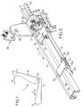
- la figure 2 est une vue en perspective représentant une glissière à mémoire selon une première forme de réalisation de l'invention,
- le figure 3 est une vue de détail représentant la position de plusieurs organes essentiels de la glissière de la figure 2 dans sa position normale d'utilisation,
- la figure 4 est une vue similaire à la figure 3, pendant le réglage de la position longitudinale du siège,
- la figure 5 est une vue similaire aux figures 3 et 4, lorsque le profilé mobile est déplacé vers l'avant, sans déplacement du patin de mémorisation, lors de l'accès aux places arrière,
- la figure 6 est une vue en perspective d'une glissière selon une autre forme de réalisation de l'invention, et
- la figure 7 est une vue de détail de la figure 6.
- FIG. 1 is a schematic view showing a seat which can be fitted with at least one memory slide according to the invention,
- Figure 2 is a perspective view showing a memory slide according to a first embodiment of the invention,
- FIG. 3 is a detailed view showing the position of several essential members of the slide of FIG. 2 in its normal position of use,
- FIG. 4 is a view similar to FIG. 3, during the adjustment of the longitudinal position of the seat,
- FIG. 5 is a view similar to FIGS. 3 and 4, when the movable profile is moved forward, without displacement of the storage pad, when accessing the rear seats,
- FIG. 6 is a perspective view of a slide according to another embodiment of the invention, and
- FIG. 7 is a detailed view of FIG. 6.
Sur les différentes figures, les mêmes références désignent des éléments identiques ou similaires.In the different figures, the same references designate identical or similar elements.
Comme représenté schématiquement sur la figure 1, l'invention s'applique à un siège de véhicule 1, notamment un siège avant de véhicule automobile à deux portes, c'est-à-dire un véhicule dans lequel il est nécessaire de déplacer au moins un des sièges avant pour accéder au siège arrière.As shown diagrammatically in FIG. 1, the invention applies to a vehicle seat 1, in particular a front seat of a two-door motor vehicle, that is to say a vehicle in which it is necessary to move at least one of the front seats to access the rear seat.
Le siège 1 comporte une assise 2 qui définit une partie avant 1a du siège et un dossier 3 qui définit une partie arrière 1b du siège. L'assise 2 est déplaçable en translation par rapport au plancher du véhicule, dans une direction longitudinale L, vers l'avant et vers l'arrière du siège.The seat 1 comprises a
Le siège comporte également un dossier 3 qui est monté sur l'assise 2 de façon à pouvoir pivoter autour d'un axe 3a, comme représenté par la double flèche 3b sur la figure 1, entre une position rabattue vers l'avant et une position relevée qui constitue la position d'utilisation normale du siège.The seat also includes a backrest 3 which is mounted on the
Pour accéder aux places arrière du véhicule, on déplace l'assise 2 vers l'avant au maximum dans la direction longitudinale L, et on bascule le dossier 3 également vers l'avant.To access the rear seats of the vehicle, the
L'assise 2 du siège est généralement montée sur le plancher du véhicule par l'intermédiaire de deux glissières orientées dans la direction L, au moins une de ces deux glissières pouvant être une glissière à mémoire 4 qui permet de retrouver automatiquement la position qu'occupait le siège avant d'être déplacé vers l'avant pour dégager l'accès aux places arrières du véhicule.The
Dans tous les cas, une telle glissière à mémoire comporte un premier profilé 5 dit fixe, qui est fixé au plancher du véhicule, et un deuxième profilé 6 dit mobile, qui supporte l'assise 2 du siège et qui est disposé parallèlement au profilé fixe en pouvant coulisser le long dudit profilé fixe dans la direction longitudinale L.In all cases, such a memory slide comprises a
Le profilé mobile 6 peut être immobilisé par rapport au profilé fixe 5 par un premier verrou, respectivement 7, 100, qui sera décrit ci-après en regard des différentes formes de réalisation.The
La glissière à mémoire comporte un patin de mémorisation 8 qui inclut un tronçon de profilé de même section que le profilé mobile 6, ce tronçon de profilé étant monté coulissant le long du profilé fixe 5 de la même façon que le profilé mobile 6.The memory slide comprises a
Ce patin de mémorisation 8 comporte une patte de fixation 8a pour fixer un point d'attache 19 de ceinture de sécurité.This
De préférence, parmi les trois points d'attache de la ceinture de sécurité les deux points d'attache haut et bas situés du même côté du siège sont fixés à la caisse du véhicule, et le troisième point d'attache, qui est disposé vers le milieu du véhicule et qui comporte la fermeture de la ceinture de sécurité, est fixé à la patte de fixation 8a.Preferably, among the three attachment points of the seat belt, the two top and bottom attachment points situated on the same side of the seat are fixed to the vehicle body, and the third attachment point, which is arranged towards the middle of the vehicle and which includes the closing of the seat belt, is fixed to the fixing tab 8a.
Le patin de mémorisation 8 comporte un verrou, dit deuxième verrou, respectivement 9, 101, qui coopère avec le profilé fixe 5 pour immobiliser le patin de mémorisation par rapport au profilé fixe et qui est déplaçable entre une position verrouillée où le patin de mémorisation est immobilisé par rapport au profilé fixe, et une position déverrouillée où le patin de mémorisation peut coulisser le long du profilé fixe.The
Dans les exemples représentés sur les dessins, le profilé fixe 5 comporte sur un côté un rebord longitudinal dirigé vers le bas qui présente une denture 5a, et le deuxième verrou, respectivement 9,101 comporte une plaquette qui est montée pivotante sur un support 8b solidaire du patin de mémorisation 8, autour d'un axe 9a, 101b qui est parallèle à la direction L.In the examples shown in the drawings, the fixed
La plaquette du deuxième verrou 9, 101 présente un ou plusieurs orifices 9b, 101c aptes à venir en engagement avec la denture 5a, et elle pénètre dans un évidement ménagé dans un côté du patin de mémorisation 8 de façon que les orifices 9b, 101c se trouvent sous la denture 5a.The plate of the
Le deuxième verrou est sollicité en rotation vers sa position verrouillée par un ressort, respectivement 15, 105. Sur les figures 2 à 5, il s'agit d'un ressort hélicoïdal de compression 5 monté entre le support 8b et une tête élargie située à une extrémité d'une tige 20 qui traverse le support 8b et dont l'autre extrémité traverse une lumière 9c ménagée dans la plaquette du deuxième verrou 9, ladite autre extrémité comportant également une tête élargie disposée sous le verrou 9. Sur les figures 6, 7, le ressort 105 est un ressort de torsion monté entre le support 8b et une goupille 101d à une extrémité de l'axe 101b du deuxième verrou 101.The second lock is biased in rotation towards its locked position by a spring, respectively 15, 105. In FIGS. 2 to 5, it is a
Dans une première forme de réalisation, représentée sur les figures 2 à 5, le premier verrou 7 coopère avec la denture 5a du profilé fixe.In a first embodiment, shown in Figures 2 to 5, the
Le premier verrou 7 est monté rotatif sur un côté du profilé mobile 6 autour d'un axe parallèle à la direction L, entre une position verrouillée où le premier verrou 7 coopère avec la denture 5a pour immobiliser le profilé mobile 6 par rapport au profilé fixe, et une position déverrouillée où le profilé mobile 6 peut coulisser par rapport au profilé fixe.The
Le premier verrou 7 comporte une plaquette 7a sensiblement plane qui présente une rangée d'orifices 7b aptes à venir en engagement avec la denture 5a, la plaquette 7a pénétrant à l'intérieur du profilé mobile 6 par un évidement ménagé sur un côté de ce profilé mobile, de façon que les orifices 7b se trouvent sous la denture 5a.The
La plaque 7a du premier verrou est solidaire d'un levier 13 lui-même constitué d'une plaque sensiblement plane perpendiculaire à la plaquette 7a, ce levier permettant de déplacer le deuxième verrou 7 vers sa position déverrouillée.The
Le levier 13 peut être actionné par exemple au moyen d'un câble (non représenté) dont une extrémité est fixée audit levier par un trou 13a ménagé dans ce levier.The
Enfin, la plaquette 7a est également solidaire d'une douille cylindrique 7c qui s'étend axialement parallèlement à la direction L, et qui est montée rotative à mouvement perdu autour d'un arbre de commande 12 qui la traverse.Finally, the
L'arbre de commande 12 s'étend parallèlement à la direction L entre une première extrémité 10, dite extrémité d'accouplement et une deuxième extrémité dotée d'un levier de commande 12a ou de tout autre moyen permettant de faire tourner l'arbre de commande 12 autour de son axe.The
L'arbre de commande 12 tourillonne sur deux flasques 22a d'un support 22 qui est fixé au profilé mobile 6, ces deux flasques 22a étant disposés de part et d'autre de la douille 7c.The
D'autre part, l'arbre de commande 12 tourillonne également sur un flasque 23a d'un autre support 23 également fixé au profilé mobile 6.On the other hand, the
Un ressort de torsion 21, monté entre le support 23 et une goupille 24 de l'arbre de commande 12, sollicite ledit arbre de commande 12 vers une position de repos qui est définie par la butée de la goupille 24 contre une partie 23b du support 23. A partir de cette position de repos, l'arbre de commande 12 peut être déplacé en rotation jusqu'à une position d'actionnement, où il entraîne les premier et deuxième verrous 7, 9 dans leur position déverrouillée, comme il sera vu ci-après.A
Le premier verrou 7 est sollicité en rotation autour de l'arbre de commande 12 vers sa position verrouillée, par une ressort de flexion 14 sensiblement en forme de U, dont une branche est disposée au-dessus du support 22 et pénètre dans un orifice 22b de ce support, et dont l'autre branche pénètre dans un orifice 13b de la plaque constituant le levier 13.The
L'arbre de commande 12 entraîne en rotation le premier verrou 7 au moyen d 'une goupille 25 solidaire dudit arbre de commande, qui traverse une lumière 7d de direction circonférentielle ménagée dans la douille cylindrique 7c du premier verrou.The
Lorsque l'arbre de commande 12 est dans sa position de repos et le premier verrou 7 dans sa position verrouillée, comme représenté sur les figures 2 et 3, la lumière 7d ménage deux jeux angulaires dans deux sens de rotation opposés entre l'arbre de commande et le premier verrou:
- un premier jeu angulaire permettant au premier verrou de se déplacer de sa position verrouillée jusqu'à sa position déverrouillée sans entraîner en rotation l'arbre de commande 12,
- et un deuxième jeu angulaire prévu pour que la rotation de l'arbre de commande 12 de sa position de repos jusqu'à sa position d'actionnement s'effectue d'abord sans rotation du
premier verrou 7 jusqu'au rattrapage dudit deuxième jeu angulaire, après quoi l'arbre de commande 12 entraîne le premier verrou jusqu'à sa position déverrouillée.
- a first angular play allowing the first lock to move from its locked position to its unlocked position without driving the
control shaft 12 in rotation, - and a second angular clearance provided so that the rotation of the
control shaft 12 from its rest position to its actuation position is carried out first without rotation of thefirst lock 7 until the catching of said second angular clearance , after which thecontrol shaft 12 drives the first latch to its unlocked position.
Sur le support 22 est également fixée une patte 26 sur laquelle un cliquet 16 est monté rotatif autour d'un axe 16a, le cliquet 16 étant déplaçable entre une position d'engagement où il bute contre une partie de la plaque constituant le levier 13 en bloquant ainsi le premier verrou 7 dans sa position déverrouillée, et une position effacée où il n'interfère pas avec le premier verrou.On the
Le cliquet 16 est sollicité vers sa position d'engagement par un ressort 17 de torsion monté entre ledit cliquet et la patte 26.The
Le cliquet 16 coopère en outre avec un doigt de butée 18 solidaire du patin de mémorisation 8, ce doigt de butée étant prévu pour déplacer et maintenir le cliquet 16 dans sa position effacée lorsque le profilé mobile 6 est dans sa position mémorisée.The
Par ailleurs, l'axe 9a du deuxième verrou 9 est disposé dans le prolongement de l'arbre de commande 12, et cet axe est solidaire d'une douille réceptrice 11 qui coopère avec l'extrémité d'accouplement 10 de l'arbre de commande 12 pour à la fois commander la rotation du deuxième verrou 9 et solidariser le patin de mémorisation avec le profilé mobile 6.Furthermore, the
La douille réceptrice 11 comporte un évidement central cylindrique lla prévu pour recevoir l'extrémité d'accouplement 10 de l'arbre 12. Cet évidement central 11a communique avec deux fentes 11b diamétralement opposées qui s'étendent axialement et radialement en traversant la paroi de la douille 11, lesdites fentes 11b communiquant elles-mêmes, à leur extrémité proche de l'axe 9a, respectivement avec deux fentes 11c qui s'étendent radialement et circonférentiellement en traversant également la paroi de la douille 11. Les fentes 11c présentent chacune une étendue angulaire voisine du deuxième jeu angulaire susmentionné.The receiving
Les fentes 11b et 11c sont prévues pour recevoir une goupille 10a solidaire de l'arbre de commande 12, qui s'étend perpendiculairement à l'arbre 12 en formant deux ergots radialement opposés, ces ergots étant disposés en correspondance avec les fentes 11b lorsque l'arbre de commande 12 est dans sa position de repos.The
Le dispositif des figures 2 à 5 fonctionne comme suit.The device of Figures 2 to 5 operates as follows.
Tant que le profilé mobile 6 est dans sa position mémorisée, que l'arbre de commande 12 est dans sa position de repos et que le premier verrou 7 est dans sa position verrouillée, comme représenté sur les figures 2 et 3, ce qui constitue la configuration normale de la glissière pendant l'utilisation du siège, le profilé mobile et le patin de mémorisation 8 sont immobilisés par rapport au profilé fixe 5 par les premier et deuxième verrous 7 et 9, le cliquet 16 est maintenu dans sa position effacée par le doigt de butée 18, et la goupille 10a est engagée au fond des deux fentes 11b de la douille réceptrice 11.As long as the
Lorsque l'utilisateur veut régler la position longitudinale de l'assise 2 du siège, il agit sur le levier 12a de l'arbre de commande 12, de façon à faire tourner l'arbre de commande 12 jusqu'à sa position d'actionnement, comme représenté sur la figure 4. Au cours de ce mouvement, l'arbre de commande 12 pivote d'abord sans entraîner les verrous 7 et 9, tandis que la goupille 25 se déplace dans la lumière 7d en rattrapant le deuxième jeu susmentionné et que la goupille 10a se déplace dans les fentes 11b de la douille réceptrice 11 en réalisant ainsi un couplage à baïonnette entre la douille réceptrice 11 et l'extrémité d'accouplement 10 du levier de commande, ce qui solidarise le patin de mémorisation 8 avec le profilé mobile 6.When the user wants to adjust the longitudinal position of the
Après cette première phase du mouvement de rotation de l'arbre de commande 12, ledit arbre de commande entraîne les deux verrous 7 et 9 en rotation jusqu'à leur position déverrouillée, après quoi il est possible de régler la position longitudinale de l'assise du siège en faisant coulisser le profilé mobile 6 et le patin de mémorisation 8 simultanément le long du profilé fixe 5. Au cours de ce mouvement, le cliquet 16 est maintenu dans sa position effacée par le doigt de butée 18.After this first phase of the movement of rotation of the
Lorsque le réglage de la position longitudinale du siège est terminé, l'utilisateur relâche le levier 12a, de sorte que l'arbre de commande est ramené dans sa position de repos par le ressort 21, et les premier et deuxième verrous 7 et 9 sont ramenés dans leur position de repos respectivement par les ressorts 14 et 15.When the adjustment of the longitudinal position of the seat is completed, the user releases the
A partir de la position réglée par l'utilisateur, lorsqu'il est nécessaire d'avancer au maximum l'assise du siège pour dégager l'accès aux places arrière du véhicule, l'utilisateur agit sur le levier 13, par l'intermédiaire d'un câble disposé généralement le long du dossier et relié à un levier de commande qui permet simultanément de rabattre le dossier du siège vers l'avant, et il exerce simultanément une poussée vers l'avant du siège.From the position set by the user, when it is necessary to move the seat as far as possible to clear access to the rear seats of the vehicle, the user acts on
Au cours de ce mouvement, le levier 13 subit une force A qui fait pivoter le premier verrou 7 jusqu'à sa position déverrouillée, sans que l'arbre de commande 12 soit influencé par ce mouvement, du fait du premier jeu angulaire prévu entre l'arbre de commande 12 et le premier verrou 7.During this movement, the
Simultanément, une force B est exercée sur le profilé mobile 6 dans la direction longitudinale L et vers l'avant, de sorte que le profilé mobile 6 coulisse vers l'avant avec l'assise du siège. La goupille 10a de l'extrémité d'accouplement du levier de commande 12 n'interfère pas avec ce mouvement, puisque l'arbre de commande 12 est toujours dans sa position de repos, de sorte que ladite goupille 10a est disposée en correspondance avec les fentes axiales 11b de la douille réceptrice 11 solidaire du deuxième verrou 9.Simultaneously, a force B is exerted on the
Dès qu'un petit mouvement vers l'avant du profilé mobile 6 a eu lieu, le cliquet 16 n'est plus maintenu par le doigt de butée 18, de sorte que ledit cliquet est déplacé dans sa position d'engagement par le ressort 17. Par conséquent, même si l'action de l'utilisateur sur le levier 13 est relâchée très rapidement, le premier verrou 7 est maintenu dans sa position déverrouillée par le cliquet 16.As soon as a small forward movement of the
L'utilisateur peut donc librement avancer au maximum l'assise 2 du siège, tandis que le patin de mémorisation 8 reste dans sa position initiale, puisque le deuxième verrou 9 est toujours dans sa position verrouillée.The user can therefore freely advance the
Lorsque l'utilisateur veut retrouver la position préalablement réglée du siège, il lui suffit de reculer l'assise 2 du siège au maximum, jusqu'à ce que le profilé mobile 6 vienne buter contre le patin de mémorisation 8, c'est-à-dire jusqu'à ce que le profilé mobile 6 revienne dans sa position mémorisée.When the user wants to return to the previously adjusted position of the seat, he just has to move the
A ce moment, l'extrémité d'accouplement 10 de l'arbre de commande 12 pénètre à nouveau dans l'évidement 11a de la douille réceptrice 11, tandis que la goupille 10a de cette extrémité d'accouplement pénètre dans les fentes 11b de la douille réceptrice.At this time, the
Simultanément, le doigt de butée 18 solidaire du patin de mémorisation 8 déplace le cliquet 16 dans sa position effacée, de sorte que le premier verrou 7 est ramené dans sa position verrouillée par le ressort 14.Simultaneously, the
Le dispositif se retrouve donc à nouveau dans la configuration représentée sur les figures 2 et 3.The device is therefore again found in the configuration shown in FIGS. 2 and 3.
Dans la deuxième forme de réalisation de l'invention, représentée sur les figures 6 et 7, le premier verrou 100 ne coopère pas avec la denture 5a du profilé fixe, mais avec le deuxième verrou 101 qui lui-même coopère avec la denture 5a du profilé fixe.In the second embodiment of the invention, shown in FIGS. 6 and 7, the
Le premier verrou 100 est monté rotatif sur un côté du profilé mobile 6, autour d'un axe 100a perpendiculaire à la direction L et parallèle à la plaquette 101a du deuxième verrou lorsque le deuxième verrou est dans sa position verrouillée.The
Le premier verrou est rappelé vers une position dite de repos où il est disposé longitudinalement sensiblement parallèlement à la direction L, au moyen d'un ressort de flexion 104 dont une extrémité est fixée sur le côté du profilé mobile 6, et dont l'autre extrémité est fixée à un ergot 102 du premier verrou.The first lock is returned to a so-called rest position where it is arranged longitudinally substantially parallel to the direction L, by means of a
A partir de cette position de repos, le premier verrou peut être déplacé en rotation dans une première direction 106, et dans une deuxième direction 107 opposée à la première.From this rest position, the first latch can be rotated in a
Le premier verrou 100 comporte un bras 100b qui s'étend sensiblement parallèlement à la direction L vers le patin de mémorisation 8, et qui, lorsque le profilé mobile 6 est dans sa position mémorisée, pénètre dans un espace 108 laissé libre au-dessus de la plaquette 101a du deuxième verrou et au-dessous du support 8b sur lequel est monté le deuxième verrou.The
Le bras 100b présente une extrémité distale formant une partie saillante 100c qui s'étend vers le bas, ladite partie saillante présentant de son côté le plus proche de l'axe 100a un bord d'arrêt 100d perpendiculaire à la direction longitudinale dudit bras 100b, et de son côté éloigné de l'axe 100a, un bord biais 100f.The arm 100b has a distal end forming a projecting
Le premier verrou 100 comporte également des dents 100g, qui s'étendent vers le bas à partir du bras 100b, sans aller au-delà de la partie saillante 100c, lesdites dents pouvant s'engager dans des trous correspondant 101g de la plaquette 101a du deuxième verrou.The
La partie saillante 100c est toutefois plus large que les orifices 101g, de sorte que ladite partie saillante ne peut pas pénétrer dans lesdits orifices en passant au-dessus de la plaquette 101a du deuxième verrou.The protruding
Eventuellement, les dents 100g et les orifices 101g pourraient être omis, sans sortir du cadre de la présente invention, l'accrochage du premier verrou 100 sur le deuxième verrou 101 se faissant alors uniquement par la partie saillante 100c.Optionally, the
Le dispositif de la deuxième forme de réalisation fonctionne comme suit.The device of the second embodiment operates as follows.
Dans l'état normal d'utilisation du siège supporté par la glissière, le profilé mobile 6 est dans sa position de mémorisation, le deuxième verrou 101 est dans sa position verrouillée, et le premier verrou 100 est dans sa position de repos, le bord d'arrêt 100d de sa partie saillante 100c étant engagée contre un bord correspondant 101f de la plaquette 101a du deuxième verrou, et les dents 100g du premier verrou étant engagées dans les trous correspondant 101g de la plaquette 101a du deuxième verrou.In the normal state of use of the seat supported by the slide, the
Lorsque l'utilisateur du siège veut régler le position longitudinale de l'assise de ce siège, il lui suffit de faire pivoter le premier verrou 100 dans la première direction 106. Pour cela, l'ergot 102 susmentionné, qui est disposé à l'opposé de la tige 100b par rapport à l'axe 100a, peut éventuellement être fixé à un câble lui-même commandé par un levier accessible à l'utilisateur (non représenté), l'action de l'utilisateur se traduisant par l'application sur l'ergot 102 d'une force C dirigée vers le haut.When the user of the seat wants to adjust the longitudinal position of the seat of this seat, it suffices to rotate the
Le pivotement du premier verrou 100 dans la première direction 106 entraîne un pivotement du deuxième verrou 101 jusqu'à sa position déverrouillée, par appui du bras 100b sur la plaquette 101a du deuxième verrou.The pivoting of the
Ainsi, le profilé mobile 6 peut être déplacé librement le long du profilé fixe 5, et le patin de mémorisation 8 reste accouplé au profilé mobile 6 du fait de l'engagement du bord d'arrêt 100d du premier verrou contre le bord correspondant 101f du deuxième verrou, de fait de la butée d'une extrémité du profilé mobile 6 contre une extrémité du patin de mémorisation 8, et également, le cas échéant, du fait de l'engagement des dents 100g du premier verrou dans les trous 101g du deuxième verrou.Thus, the
Lorsque la position longitudinale de l'assise du siège a été réglée, s'il est nécessaire d'avancer au maximum l'assise du siège pour dégager l'accès aux places arrière du véhicule, l'utilisateur fait pivoter le premier verrou 100 dans la deuxième direction, ce qui dégage le bord d'arrêt 100d du bord correspondant 101f et les dents 100g des orifices 101g.When the longitudinal position of the seat cushion has been adjusted, if it is necessary to advance the seat cushion as much as possible to clear access to the rear seats of the vehicle, the user pivots the
Simultanément, l'utilisateur repousse le siège vers l'avant, de sorte qu'après une très léger déplacement vers l'avant de l'assise du siège, ce qui correspond à un mouvement identique du profilé mobile 6 supportant l'assise, le bras 100b du premier verrou ne se trouve plus à l'intérieur de l'espace 108 au-dessus de la plaquette 101a du deuxième verrou, de sorte que l'action de l'utilisateur sur le premier verrou peut être relâchée.Simultaneously, the user pushes the seat forward, so that after a very slight forward movement of the seat cushion, which corresponds to an identical movement of the
Le mouvement de pivotement du premier verrou 100 peut être obtenu par exemple par application d'une force D dirigée vers le haut sur un ergot 103 du premier verrou qui est disposé entre l'axe 100a et la tige 100b, l'application de cette force pouvant être obtenue par exemple au moyen d'un câble qui est disposé généralement le long du dossier et qui est relié à un levier de commande (non représenté).The pivoting movement of the
Ainsi, l'utilisateur peut avancer l'assise 2 du siège, et donc le profilé mobile 6, au maximum, tandis que le patin de mémorisation 8 reste en place, puisque le deuxième verrou 101 est toujours dans sa position verrouillée.Thus, the user can advance the
Lorsque l'utilisateur veut remettre l'assise du siège dans sa position mémorisée, il lui suffit de déplacer cette assise vers l'arrière dans la direction L, de sorte que le profilé mobile 6 revient vers le patin de mémorisation 8 jusqu'à sa position mémorisée, où il bute contre ledit patin.When the user wants to return the seat base to its memorized position, it suffices to move this seat backwards in the direction L, so that the
Au cours de ce mouvement, le bord biais 100f du bras 100b du premier verrou coopère avec la plaquette 101a du deuxième verrou pour faire pivoter le premier verrou dans la deuxième direction par effet de came, de façon que le bras 100b du premier verrou passe au-dessus de la plaquette 101a.During this movement, the
Ce pivotement du premier verrou 100 n'entraîne pas de pivotement du deuxième verrou 101 vers sa position déverrouillée, du fait que le ressort 105 qui rappelle le deuxième verrou dans sa position verrouillée a une force suffisante.This pivoting of the
Du fait que la partie saillante 100c est plus large que les orifices 101g, le verrouillage du premier verrou 100 sur la plaquette 101a du deuxième verrou n'a lieu que lorsque la partie saillante 100c a dépassé la plaquette 101a.Due to the fact that the
Ainsi, la glissière se retrouve dans sa position normale d'utilisation.Thus, the slide is returned to its normal position of use.
Claims (9)
Applications Claiming Priority (2)
| Application Number | Priority Date | Filing Date | Title |
|---|---|---|---|
| FR9408490 | 1994-07-08 | ||
| FR9408490A FR2722149B1 (en) | 1994-07-08 | 1994-07-08 | SLIDE FOR VEHICLE SEAT, AND VEHICLE SEAT EQUIPPED WITH SUCH A SLIDE |
Publications (2)
| Publication Number | Publication Date |
|---|---|
| EP0691237A1 true EP0691237A1 (en) | 1996-01-10 |
| EP0691237B1 EP0691237B1 (en) | 1997-03-26 |
Family
ID=9465191
Family Applications (1)
| Application Number | Title | Priority Date | Filing Date |
|---|---|---|---|
| EP95401614A Expired - Lifetime EP0691237B1 (en) | 1994-07-08 | 1995-07-05 | Vehicle seat slide |
Country Status (6)
| Country | Link |
|---|---|
| US (1) | US5641145A (en) |
| EP (1) | EP0691237B1 (en) |
| JP (1) | JPH0840200A (en) |
| DE (1) | DE69500197T2 (en) |
| ES (1) | ES2102272T3 (en) |
| FR (1) | FR2722149B1 (en) |
Cited By (3)
| Publication number | Priority date | Publication date | Assignee | Title |
|---|---|---|---|---|
| DE19617690A1 (en) * | 1996-05-03 | 1997-11-13 | Faure Bertrand Sitztech Gmbh | Seat rail arrangement for road vehicle |
| FR2778613A1 (en) * | 1998-05-12 | 1999-11-19 | Faure Bertrand Equipements Sa | SLIDE FOR VEHICLE SEAT WITH LONGITUDINAL ADJUSTMENT MEMORY AND SEAT COMPRISING SUCH A SLIDE |
| US6227596B1 (en) | 1998-03-24 | 2001-05-08 | Bertrand Faure Equipements Sa | Slide rail for vehicle seat and seat comprising such a slide rail |
Families Citing this family (15)
| Publication number | Priority date | Publication date | Assignee | Title |
|---|---|---|---|---|
| JP3646356B2 (en) * | 1995-06-30 | 2005-05-11 | アイシン精機株式会社 | Seat slide device |
| KR100289093B1 (en) * | 1996-09-26 | 2001-05-02 | 가또 게이 | Vehicle seat slide device |
| FR2756522B1 (en) * | 1996-12-03 | 1999-01-29 | Faure Bertrand Equipements Sa | SLIDE FOR VEHICLE SEAT AND SEAT COMPRISING SUCH A SLIDE |
| US5878859A (en) * | 1997-05-09 | 1999-03-09 | Lear Corporation | Manual vehicle seat adjuster with quick release clutch |
| US6131871A (en) * | 1998-05-07 | 2000-10-17 | Lear Automotive Dearborn, Inc | Manually actuated seat adjuster |
| FR2783923B1 (en) * | 1998-09-30 | 2000-12-29 | Peugeot | DEVICE FOR CONTROLLING THE LOCKING OF A FIXED POSITION |
| US6161756A (en) * | 1999-02-04 | 2000-12-19 | Upton; Robert D. | Adjustable mailbox extender |
| FR2796342B1 (en) * | 1999-07-15 | 2001-08-03 | Peugeot Citroen Automobiles Sa | DEVICE FOR LIMITING THE REVERSE OF A MOTOR VEHICLE SEAT |
| ES2253670T3 (en) * | 2002-04-30 | 2006-06-01 | BROSE FAHRZEUGTEILE GMBH & CO. KG, COBURG | LONGITUDINAL BEARING ROAD FOR THE SEAT OF A MOTOR VEHICLE. |
| CN1660625B (en) * | 2004-02-24 | 2010-05-05 | 爱信精机株式会社 | Seat sliding device for vehicle |
| JP4631327B2 (en) * | 2004-06-28 | 2011-02-16 | アイシン精機株式会社 | Vehicle seat device |
| DE202006005103U1 (en) * | 2006-03-30 | 2007-08-09 | Brose Fahrzeugteile Gmbh & Co. Kommanditgesellschaft, Coburg | Adjustment system for a vehicle seat |
| DE102009033892B4 (en) * | 2009-07-20 | 2017-03-30 | Lear Corporation | Seat rail assembly with seat lock and memory element for vehicle seat |
| US8678463B2 (en) * | 2012-06-21 | 2014-03-25 | GM Global Technology Operations LLC | Vehicle seat assembly and method of controlling a vehicle seat assembly |
| KR20220014920A (en) * | 2020-07-29 | 2022-02-08 | 현대자동차주식회사 | Seat support assembly for automobile |
Citations (4)
| Publication number | Priority date | Publication date | Assignee | Title |
|---|---|---|---|---|
| GB261460A (en) * | 1925-08-15 | 1926-11-15 | Arthur William Chapman | Improvements relating to slidable seats for vehicles, and the like |
| US1684944A (en) | 1925-07-15 | 1928-09-18 | Chapman Arthur William | Slidable seat for vehicles and the like |
| FR2430330A1 (en) * | 1978-07-07 | 1980-02-01 | Cousin Cie Ets A & M Freres | Longitudinal vehicle seat adjuster - has supplementary member which locates initial position for automatic return |
| EP0537057A1 (en) * | 1991-10-11 | 1993-04-14 | Bertrand Faure Automobile "B.F.A." | Slide for a vehicle seat with a fixed return position |
-
1994
- 1994-07-08 FR FR9408490A patent/FR2722149B1/en not_active Expired - Fee Related
-
1995
- 1995-07-05 ES ES95401614T patent/ES2102272T3/en not_active Expired - Lifetime
- 1995-07-05 US US08/498,723 patent/US5641145A/en not_active Expired - Fee Related
- 1995-07-05 EP EP95401614A patent/EP0691237B1/en not_active Expired - Lifetime
- 1995-07-05 DE DE69500197T patent/DE69500197T2/en not_active Expired - Fee Related
- 1995-07-10 JP JP7173800A patent/JPH0840200A/en not_active Withdrawn
Patent Citations (4)
| Publication number | Priority date | Publication date | Assignee | Title |
|---|---|---|---|---|
| US1684944A (en) | 1925-07-15 | 1928-09-18 | Chapman Arthur William | Slidable seat for vehicles and the like |
| GB261460A (en) * | 1925-08-15 | 1926-11-15 | Arthur William Chapman | Improvements relating to slidable seats for vehicles, and the like |
| FR2430330A1 (en) * | 1978-07-07 | 1980-02-01 | Cousin Cie Ets A & M Freres | Longitudinal vehicle seat adjuster - has supplementary member which locates initial position for automatic return |
| EP0537057A1 (en) * | 1991-10-11 | 1993-04-14 | Bertrand Faure Automobile "B.F.A." | Slide for a vehicle seat with a fixed return position |
Cited By (4)
| Publication number | Priority date | Publication date | Assignee | Title |
|---|---|---|---|---|
| DE19617690A1 (en) * | 1996-05-03 | 1997-11-13 | Faure Bertrand Sitztech Gmbh | Seat rail arrangement for road vehicle |
| DE19617690C2 (en) * | 1996-05-03 | 1999-07-08 | Faure Bertrand Sitztech Gmbh | Seat rail arrangement, in particular for motor vehicle seats |
| US6227596B1 (en) | 1998-03-24 | 2001-05-08 | Bertrand Faure Equipements Sa | Slide rail for vehicle seat and seat comprising such a slide rail |
| FR2778613A1 (en) * | 1998-05-12 | 1999-11-19 | Faure Bertrand Equipements Sa | SLIDE FOR VEHICLE SEAT WITH LONGITUDINAL ADJUSTMENT MEMORY AND SEAT COMPRISING SUCH A SLIDE |
Also Published As
| Publication number | Publication date |
|---|---|
| DE69500197T2 (en) | 1997-10-30 |
| DE69500197D1 (en) | 1997-04-30 |
| JPH0840200A (en) | 1996-02-13 |
| ES2102272T3 (en) | 1997-07-16 |
| EP0691237B1 (en) | 1997-03-26 |
| US5641145A (en) | 1997-06-24 |
| FR2722149A1 (en) | 1996-01-12 |
| FR2722149B1 (en) | 1996-09-20 |
Similar Documents
| Publication | Publication Date | Title |
|---|---|---|
| EP0691237B1 (en) | Vehicle seat slide | |
| EP0798154B1 (en) | Slide for vehicle seat and seat with such a slide | |
| EP0780259B1 (en) | Seat with variable configuration for motor vehicles | |
| FR2766137A1 (en) | VEHICLE SEAT HAVING A JOINT MECHANISM | |
| FR2722150A1 (en) | ARTICULATION WITH SEAT ADJUSTMENT POSITION | |
| EP0913293A1 (en) | Hinge mechanism for vehicle seat and vehicle seat equipped with such a mechanism | |
| FR2822419A1 (en) | VEHICLE SEAT HAVING A JOINT MECHANISM | |
| FR2769268A1 (en) | REMOVABLE FOLDABLE SEAT | |
| FR2777837A1 (en) | ARTICULATION MECHANISM FOR VEHICLE SEAT, AND VEHICLE SEAT HAVING SUCH A MECHANISM | |
| FR2766138A1 (en) | ARTICULATION MECHANISM FOR VEHICLE SEAT, AND VEHICLE SEAT EQUIPPED WITH SUCH A MECHANISM | |
| FR2766139A1 (en) | Hinge assembly for vehicle seat | |
| FR2796015A1 (en) | DEVICE FOR ADJUSTING A DOUBLE ARTICULATED SEAT BACK BY A SINGLE CONTROL | |
| FR2829439A1 (en) | Vehicle seat under-frame has operating device with release finger designed to abut against abutment face integral with release cam when in active position to hold actuating portion in second position | |
| FR2832675A1 (en) | Hinge mechanism for vehicle seat, has e.g. flats, formed at free ends of teeth of slug in second hinge so that same teeth can be set in intermediate position between limit of engagement position and maximal separate position | |
| FR2756522A1 (en) | Slider for vehicle seat | |
| FR2841838A1 (en) | VEHICLE SEAT HAVING A JOINT MECHANISM | |
| EP0800952B1 (en) | Forwardly displaceable automotive vehicle seat, to access the rear space | |
| FR2770811A1 (en) | Vehicle seat with tilting seat back | |
| FR2884191A1 (en) | Motor vehicle`s seat articulation mechanism, has rising step in shape of wedge pushing back locking step in locking position when rising step is in active position and unlocking position when rising step is in pitch position | |
| EP0614781B1 (en) | Vehicle seat and its application to a rear seat | |
| EP0748916B1 (en) | Actuator for a gate or other closure panel | |
| EP3063035B1 (en) | Retractable seat for a vehicle | |
| EP0402195A1 (en) | Demountable fastening device for the rear seat of a motor vehicle | |
| FR2779688A1 (en) | Vehicle seat, with tilting part seat back, with safety device | |
| FR2796897A1 (en) | Seat for car has safety system having control element not interacting with hinged part of backrest, or engaged in different notches of hinged part, depending of position of seat |
Legal Events
| Date | Code | Title | Description |
|---|---|---|---|
| PUAI | Public reference made under article 153(3) epc to a published international application that has entered the european phase |
Free format text: ORIGINAL CODE: 0009012 |
|
| AK | Designated contracting states |
Kind code of ref document: A1 Designated state(s): DE ES FR GB IT |
|
| 17P | Request for examination filed |
Effective date: 19960119 |
|
| GRAG | Despatch of communication of intention to grant |
Free format text: ORIGINAL CODE: EPIDOS AGRA |
|
| GRAH | Despatch of communication of intention to grant a patent |
Free format text: ORIGINAL CODE: EPIDOS IGRA |
|
| 17Q | First examination report despatched |
Effective date: 19960814 |
|
| GRAH | Despatch of communication of intention to grant a patent |
Free format text: ORIGINAL CODE: EPIDOS IGRA |
|
| RAP1 | Party data changed (applicant data changed or rights of an application transferred) |
Owner name: BERTRAND FAURE EQUIPEMENTS S.A. |
|
| GRAA | (expected) grant |
Free format text: ORIGINAL CODE: 0009210 |
|
| AK | Designated contracting states |
Kind code of ref document: B1 Designated state(s): DE ES FR GB IT |
|
| REF | Corresponds to: |
Ref document number: 69500197 Country of ref document: DE Date of ref document: 19970430 |
|
| ITF | It: translation for a ep patent filed |
Owner name: BARZANO' E ZANARDO MILANO S.P.A. |
|
| GBT | Gb: translation of ep patent filed (gb section 77(6)(a)/1977) |
Effective date: 19970516 |
|
| REG | Reference to a national code |
Ref country code: ES Ref legal event code: FG2A Ref document number: 2102272 Country of ref document: ES Kind code of ref document: T3 |
|
| PLBE | No opposition filed within time limit |
Free format text: ORIGINAL CODE: 0009261 |
|
| STAA | Information on the status of an ep patent application or granted ep patent |
Free format text: STATUS: NO OPPOSITION FILED WITHIN TIME LIMIT |
|
| 26N | No opposition filed | ||
| PGFP | Annual fee paid to national office [announced via postgrant information from national office to epo] |
Ref country code: ES Payment date: 19980717 Year of fee payment: 4 |
|
| PG25 | Lapsed in a contracting state [announced via postgrant information from national office to epo] |
Ref country code: GB Free format text: LAPSE BECAUSE OF NON-PAYMENT OF DUE FEES Effective date: 19990705 |
|
| PG25 | Lapsed in a contracting state [announced via postgrant information from national office to epo] |
Ref country code: ES Free format text: LAPSE BECAUSE OF NON-PAYMENT OF DUE FEES Effective date: 19990706 |
|
| GBPC | Gb: european patent ceased through non-payment of renewal fee |
Effective date: 19990705 |
|
| PGFP | Annual fee paid to national office [announced via postgrant information from national office to epo] |
Ref country code: DE Payment date: 20000705 Year of fee payment: 6 |
|
| PG25 | Lapsed in a contracting state [announced via postgrant information from national office to epo] |
Ref country code: DE Free format text: LAPSE BECAUSE OF NON-PAYMENT OF DUE FEES Effective date: 20020501 |
|
| REG | Reference to a national code |
Ref country code: ES Ref legal event code: FD2A Effective date: 20000810 |
|
| PG25 | Lapsed in a contracting state [announced via postgrant information from national office to epo] |
Ref country code: IT Free format text: LAPSE BECAUSE OF NON-PAYMENT OF DUE FEES;WARNING: LAPSES OF ITALIAN PATENTS WITH EFFECTIVE DATE BEFORE 2007 MAY HAVE OCCURRED AT ANY TIME BEFORE 2007. THE CORRECT EFFECTIVE DATE MAY BE DIFFERENT FROM THE ONE RECORDED. Effective date: 20050705 |
|
| PGFP | Annual fee paid to national office [announced via postgrant information from national office to epo] |
Ref country code: FR Payment date: 20050728 Year of fee payment: 11 |
|
| REG | Reference to a national code |
Ref country code: FR Ref legal event code: ST Effective date: 20070330 |
|
| PG25 | Lapsed in a contracting state [announced via postgrant information from national office to epo] |
Ref country code: FR Free format text: LAPSE BECAUSE OF NON-PAYMENT OF DUE FEES Effective date: 20060731 |