EP0697510A2 - Power train control method and control apparatus for a vehicle - Google Patents
Power train control method and control apparatus for a vehicle Download PDFInfo
- Publication number
- EP0697510A2 EP0697510A2 EP95304955A EP95304955A EP0697510A2 EP 0697510 A2 EP0697510 A2 EP 0697510A2 EP 95304955 A EP95304955 A EP 95304955A EP 95304955 A EP95304955 A EP 95304955A EP 0697510 A2 EP0697510 A2 EP 0697510A2
- Authority
- EP
- European Patent Office
- Prior art keywords
- engine
- air
- fuel ratio
- power train
- lean
- Prior art date
- Legal status (The legal status is an assumption and is not a legal conclusion. Google has not performed a legal analysis and makes no representation as to the accuracy of the status listed.)
- Withdrawn
Links
Images


Classifications
-
- F—MECHANICAL ENGINEERING; LIGHTING; HEATING; WEAPONS; BLASTING
- F02—COMBUSTION ENGINES; HOT-GAS OR COMBUSTION-PRODUCT ENGINE PLANTS
- F02D—CONTROLLING COMBUSTION ENGINES
- F02D43/00—Conjoint electrical control of two or more functions, e.g. ignition, fuel-air mixture, recirculation, supercharging or exhaust-gas treatment
-
- B—PERFORMING OPERATIONS; TRANSPORTING
- B60—VEHICLES IN GENERAL
- B60W—CONJOINT CONTROL OF VEHICLE SUB-UNITS OF DIFFERENT TYPE OR DIFFERENT FUNCTION; CONTROL SYSTEMS SPECIALLY ADAPTED FOR HYBRID VEHICLES; ROAD VEHICLE DRIVE CONTROL SYSTEMS FOR PURPOSES NOT RELATED TO THE CONTROL OF A PARTICULAR SUB-UNIT
- B60W10/00—Conjoint control of vehicle sub-units of different type or different function
- B60W10/04—Conjoint control of vehicle sub-units of different type or different function including control of propulsion units
-
- B—PERFORMING OPERATIONS; TRANSPORTING
- B60—VEHICLES IN GENERAL
- B60W—CONJOINT CONTROL OF VEHICLE SUB-UNITS OF DIFFERENT TYPE OR DIFFERENT FUNCTION; CONTROL SYSTEMS SPECIALLY ADAPTED FOR HYBRID VEHICLES; ROAD VEHICLE DRIVE CONTROL SYSTEMS FOR PURPOSES NOT RELATED TO THE CONTROL OF A PARTICULAR SUB-UNIT
- B60W10/00—Conjoint control of vehicle sub-units of different type or different function
- B60W10/10—Conjoint control of vehicle sub-units of different type or different function including control of change-speed gearings
-
- B—PERFORMING OPERATIONS; TRANSPORTING
- B60—VEHICLES IN GENERAL
- B60W—CONJOINT CONTROL OF VEHICLE SUB-UNITS OF DIFFERENT TYPE OR DIFFERENT FUNCTION; CONTROL SYSTEMS SPECIALLY ADAPTED FOR HYBRID VEHICLES; ROAD VEHICLE DRIVE CONTROL SYSTEMS FOR PURPOSES NOT RELATED TO THE CONTROL OF A PARTICULAR SUB-UNIT
- B60W30/00—Purposes of road vehicle drive control systems not related to the control of a particular sub-unit, e.g. of systems using conjoint control of vehicle sub-units, or advanced driver assistance systems for ensuring comfort, stability and safety or drive control systems for propelling or retarding the vehicle
- B60W30/18—Propelling the vehicle
- B60W30/1819—Propulsion control with control means using analogue circuits, relays or mechanical links
-
- F—MECHANICAL ENGINEERING; LIGHTING; HEATING; WEAPONS; BLASTING
- F02—COMBUSTION ENGINES; HOT-GAS OR COMBUSTION-PRODUCT ENGINE PLANTS
- F02D—CONTROLLING COMBUSTION ENGINES
- F02D41/00—Electrical control of supply of combustible mixture or its constituents
- F02D41/02—Circuit arrangements for generating control signals
- F02D41/04—Introducing corrections for particular operating conditions
-
- F—MECHANICAL ENGINEERING; LIGHTING; HEATING; WEAPONS; BLASTING
- F02—COMBUSTION ENGINES; HOT-GAS OR COMBUSTION-PRODUCT ENGINE PLANTS
- F02D—CONTROLLING COMBUSTION ENGINES
- F02D41/00—Electrical control of supply of combustible mixture or its constituents
- F02D41/02—Circuit arrangements for generating control signals
- F02D41/14—Introducing closed-loop corrections
- F02D41/1438—Introducing closed-loop corrections using means for determining characteristics of the combustion gases; Sensors therefor
- F02D41/1473—Introducing closed-loop corrections using means for determining characteristics of the combustion gases; Sensors therefor characterised by the regulation method
- F02D41/1475—Regulating the air fuel ratio at a value other than stoichiometry
-
- B—PERFORMING OPERATIONS; TRANSPORTING
- B60—VEHICLES IN GENERAL
- B60W—CONJOINT CONTROL OF VEHICLE SUB-UNITS OF DIFFERENT TYPE OR DIFFERENT FUNCTION; CONTROL SYSTEMS SPECIALLY ADAPTED FOR HYBRID VEHICLES; ROAD VEHICLE DRIVE CONTROL SYSTEMS FOR PURPOSES NOT RELATED TO THE CONTROL OF A PARTICULAR SUB-UNIT
- B60W2710/00—Output or target parameters relating to a particular sub-units
- B60W2710/06—Combustion engines, Gas turbines
- B60W2710/0616—Position of fuel or air injector
- B60W2710/0622—Air-fuel ratio
-
- F—MECHANICAL ENGINEERING; LIGHTING; HEATING; WEAPONS; BLASTING
- F02—COMBUSTION ENGINES; HOT-GAS OR COMBUSTION-PRODUCT ENGINE PLANTS
- F02D—CONTROLLING COMBUSTION ENGINES
- F02D2250/00—Engine control related to specific problems or objectives
- F02D2250/18—Control of the engine output torque
- F02D2250/21—Control of the engine output torque during a transition between engine operation modes or states
Definitions
- the present invention relates to a method and an apparatus of controlling an engine power train including an engine which can operate on a lean air-fuel ratio and an automatic transmission connected to the engine for the vehicle.
- a method of controlling an air-fuel ratio previously proposed in Japanese Application Laid-open No.52825/1978 changes the stoichiometric air-fuel ratio for the lean air-fuel ratio when the operating condition of the engine is within a predetermined range. This method increases the air-fuel ratio gradually after the load on the engine has increased beyond a predetermined value and decreases the air-fuel ratio gradually to an initial air-fuel ratio when the load decreases.
- Another method previously proposed in Japanese Application Laid-open No.10224/1976 increases the air-fuel ratio when the load on the engine is in a middle-load region, and controls the air-fuel ratio so that a fuel mixture of the stoichiometric air-fuel ratio or a rich air-fuel ratio is supplied to the engine when the load is in a low-load region or a high-load region, attaching importance to an output power of the engine.
- a gear changing operation of the automatic transmission is controlled according to a shift schedule stored in a memory of a controller.
- the shift schedule is designed on the basis of the opening of the throttle valve, which is an index of the engine torque, and the vehicle speed ("Motor Fan", San-ei Shobo, p. 29, Dec., 1990).
- the lockup schedule also is designed on the basis of the opening of the throttle valve and the vehicle speed.
- the line pressure is controlled according to the opening of the throttle valve to transmit the output power of the engine efficiently to the drive shaft.
- the transition between the stoichiometric air-fuel ratio and the air-fuel ratio for lean-burn operation must be quickly completed.
- the difference between a torque when the engine is operating on the stoichiometric air-fuel ratio and a torque when the engine is operating on the lean air-fuel ratio for lean-burn operation is about 30%, the vehicle may be shocked and a driver feels that the output power of the engine is insufficient during lean-burn operation if the air-fuel ratio is changed quickly.
- a first object of the present invention is to provide the engine power train control method and control apparatus capable of quickly changing the air-fuel ratio so as to meet the requirements of the exhaust gas without causing shocks and reducing the engine torque.
- a second object of the present invention is to provide the engine power train control method and control apparatus capable of suppressing shocks due to changing the speed during lean-burn operation and of securing satisfactory operability.
- the present invention carries out transition between the air-fuel ratio for lean-burn operation and the stoichiometric air-fuel ratio by varying an air-fuel ratio command value stepwise, and controls the air amount to change the air amount of the engine stepwise during transition between lean-burn operation and non-lean-burn operation.
- the air-fuel ratio command value is determined by retrieving data previously stored in the controller according to the basic fuel amount and the engine speed and interpolating the data.
- the data to be used depends on whether or not a current air-fuel ratio command value specifies the lean air-fuel ratio.
- the air amount is controlled so that the fuel amount immediately before the transition and the fuel amount after the completion of the transition are equal to each other.
- the air amount is determined by retrieving data previously stored in the controller according to the position of the accelerator pedal which is pushed by the driver and the engine speed and interpolating the data.
- the air amount is determined only on the basis of the position of the accelerator pedal.
- the basic fuel amount is varied stepwise from a value determined on the basis of the air amount and the engine speed to a value determined on the basis of the position of the accelerator pedal and the engine speed. If the position of the accelerator pedal changes to a position outside a predetermined range during the fixed period, the basic fuel amount is determined on the basis of the air amount and the engine speed.
- the present invention uses selectively a gear changing pattern for lean-burn operation and a gear changing pattern for non-lean-burn operation.
- the gear changing operation and the lockup operation are controlled according to the position of the accelerator pedal, the engine speed and the vehicle speed, and a line pressure of the automatic transmission is determined according to the position of the accelerator pedal and the engine speed while the engine is in lean-burn operation.
- the air-fuel ratio command value is inhibited from specifying the lean air-fuel ratio.
- the air-fuel ratio command value is varied stepwise during transition between the air-fuel ratio for lean-burn operation and the stoichiometric air-fuel ratio, the air-fuel ratio can be quickly changed. Since the air amount is varied stepwise, the variation of the engine torque due to the change of air-fuel ratio can be suppressed without delay.
- the current air-fuel ratio command value specifies the lean air-fuel ratio is taken into consideration when retrieving data for determining the air-fuel ratio
- hunting between the lean air-fuel ratio and the non-lean air-fuel ratio due to the change of the basic fuel amount caused by the change of the air amount does not occur.
- the air-fuel ratio can be varied smoothly in the range for lean-burn operation, so that the combustion in the engine can be stabilized.
- the air amount is controlled so that the fuel amount immediately before the transition between the air-fuel ratio for lean-burn operation and the stoichiometric air-fuel ratio and the fuel amount after the completion of the transition are equal to each other, the engine torque remains constant regardless of the transition of the air-fuel ratio.
- the air amount for lean-burn operation is determined by retrieving data previously stored in the controller according to the position of the accelerator pedal and the engine speed and interpolating the data, and the air amount for non-lean-burn operation is determined uniquely according to the position of the accelerator pedal, the engine torque can be properly corrected at every operating point of the engine during lean-burn operation, and the performance of the engine at every operating point is the same as that of the non-lean-burn engine, when the non-lean air-fuel ratio is specified.
- an optional fuel amount can be determined when the air amount is changed stepwise.
- the basic fuel amount is determined according to the air amount and the engine speed when the position of the accelerator pedal changes to a position outside a predetermined range in a fixed period, the fuel can be fed at an appropriate fuel amount when the accelerator pedal is released or when the accelerator pedal is operated for sharp acceleration.
- an optimum shift schedule can be designed according to the air-fuel ratio.
- the gear changing operation and the lockup operation are executed according to the position of the accelerator pedal, the engine speed, the vehicle speed and the line pressure of the automatic transmission is determined on the basis of the position of the accelerator pedal and the engine speed while the engine is in lean-burn operation, an optimum shift schedule, an optimum lockup schedule and an optimum line pressure can be determined even if the engine torque decreases during lean-burn operation.
- the gear changing operation and the lockup operation are executed according to the position of the accelerator pedal and the vehicle speed, and the line pressure of the automatic transmission is determined on the basis of the position of the accelerator pedal in the engine of which the air amount changes when the air-fuel ratio changes, the optimum shift schedule, the optimum lockup schedule and the optimum line pressure can be determined even when the opening of the throttle valve does not correspond uniquely to the engine torque due to the change of the air amount resulting from the change of air-fuel ratio.
- the air-fuel ratio command value is inhibited from specifying the lean air-fuel ratio when the temperature of the oil of the automatic transmission is lower than a predetermined temperature or when it is found that a part of the automatic transmission is out of order, the lean air-fuel ratio is not determined when the temperature of the oil of the automatic transmission is comparatively low or when the automatic transmission malfunctions.
- Fig. 1 is a block diagram showing a whole configuration of the invention.
- Fig. 2 is a graph showing relations of the engine torque, the NOx, and the air-fuel ratio.
- Fig. 3 is a signal block diagram for explaining a procedure of a first embodiment of the invention.
- Fig. 4 is a flow chart of a procedure to be executed by a normal basic fuel amount determining device.
- Fig. 5 is a flow chart of a procedure to be executed by a transient basic fuel amount determining device.
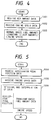
- Fig. 6 is a flow chart of a procedure to be executed by a fuel amount determining device.
- Fig. 7 is a flow chart of a procedure to be executed by an air-fuel ratio determining device.
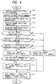
- Fig. 8 is a flow chart of a procedure to be executed by an air amount determining device.
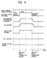
- Fig. 9 is a time diagram for explaining the effect of the first embodiment.
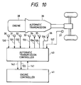
- Fig. 10 is a block diagram showing a whole configuration of a second embodiment of the invention.
- Fig. 11 is a signal block diagram for explaining a procedure to be executed by the second embodiment.
- Fig. 12 is a flow chart of a first procedure to be executed by a gear change command determining device.
- Fig 13 is a flow chart of a second procedure to be executed by the gear change command determining device.
- Fig. 14 is a flow chart of a third procedure to be executed by the gear change command determining device.
- Fig. 15 is a flow chart of a first procedure to be executed by a lockup determining device.
- Fig. 16 is a flow chart of a second procedure to be executed by the lockup determining device.
- Fig. 17 is a flow chart of a first procedure to be executed by a line pressure command determining device.
- Fig. 18 is a flow chart of a second procedure to be executed by the line pressure command determining device.
- Fig. 18 is a flow chart of a procedure to be executed by an air-fuel ratio determining device.
- Fig. 1 shows a whole configuration for illustrating a method in a first embodiment of the invention.
- the embodiment has a controller 20 which controls an engine 12 provided at least with an air amount detector 13, an air amount controlling actuator 6, an engine speed detector 2 and a fuel feed valve 29.
- the controller 20 comprises a CPU (Central Processing Unit) 23, a ROM (Read-Only Memory) 24, a RAM (Random Access Memory) 25, I/O (Input-Output) ports 21, an A/D (Analog to Disital) converter 28, an address bus 26 and a data bus 27.
- the controller 20 receives an accelerator pedal position data 101, an air amount data 112 and an engine speed data 102, and executes procedures stored in the ROM 24 to give instructions to the air amount controlling actuator 6 and the fuel feed valve 29.
- the present invention is featured by the procedures.
- Fig. 2 shows relations between an engine torque and an air-fuel ratio and between a NOx (Nitrogen Oxide) and the air-fuel ratio. Since fuel amount is reduced below that of a stoichiometric air-fuel ratio during an operation on a lean air-fuel ratio, the engine torque decreases when the air-fuel ratio is increased with an opening of a throttle valve of the engine kept fixed.
- NOx Nirogen Oxide
- a lean-burn operation of the engine is possible only at the air-fuel ratio that makes the NOx concentration of the exhaust gas lower than an allowable limit; that is, the transition of the air-fuel ratio between the stoichiometric air-fuel ratio and the air-fuel ratio for the lean-burn operation must be completed as quickly as possible to satisfy the requirements of the exhaust gas.
- a gear changing operation of the automatic transmission is controlled according to a shift schedule stored in a memory of the controller 20.
- Fig. 3 is a signal block diagram for explaining the procedures of the first embodiment.
- a transient basic fuel amount determining device 3 calculates a transient basic fuel amount data 103 for operation in an air-fuel ratio changing mode, using the accelerator pedal position data 101 provided by an accelerator pedal position detector 1 and the engine speed data 102 provided by the engine speed detector 2.
- a normal basic fuel amount determining device 4 calculates a normal basic fuel amount data 104 for operation in a normal mode, using the air amount data 112 provided by the air amount detector 13 and the engine speed data 102 provided by the engine speed detector 2.
- An air-fuel ratio determining device 5 calculates an air-fuel ratio command value 105 using the air amount data 112 and the engine speed data 102.
- a fuel amount determining device 11 determines a fuel amount 111 using the transient basic fuel amount data 103, the normal basic fuel amount data 104, the air-fuel ratio command value 105 and the accelerator pedal position data 101, and gives a command to the fuel feed valve 29.
- An air amount determining device 7 calculates an air amount command value 109 using the accelerator pedal position data 101, the engine speed data 102 and the air-fuel ratio command value 105.
- the air amount determining device 7 controls the air amount controlling actuator 6 for controlling air amount fed to the engine.
- Fig. 4 shows a procedure to be executed by the normal basic fuel amount determining device 4.
- the normal basic fuel amount determining device 4 receives the air amount data 112 and the engine speed data 102, and then calculates the normal basic fuel amount data 104 by using following expression (1).
- (Normal basic fuel amount) (Constant 1) ⁇ (Air amount)/(Engine speed)
- Fig. 5 shows a procedure to be executed by the transient basic fuel amount determining device 3.
- the transient basic fuel amount determining device 3 receives the accelerator pedal position data 101 in a step 1004 and the engine speed data 102 in a step 102, retrieves data previously stored in the controller 20 according to the accelerator pedal position data 101 and the engine speed data 102 and interpolates the data to calculate the transient basic fuel amount data 103 in a step 1006.
- the data stored in the controller 20 is a relation between the engine speed data 102, the accelerator pedal position data 101 and the normal basic fuel amount data 104. This relation relates a state where the air-fuel ratio is for a non-lean fuel mixture and the air amount controlling actuator 6 is controlled by the accelerator pedal position data 101. Therefore, the fuel amount immediately before the air-fuel ratio transition is equal to the fuel amount after the completion of the air-fuel ratio transition.
- Fig. 6 shows a procedure to be executed by the fuel amount determining device 11.
- the fuel amount determining device 11 receives the accelerator pedal position data 101 in a step 1007, the air-fuel ratio command 105 in a step 1008, the transient basic fuel amount data 103 in a step 1009 and the normal basic fuel amount data 104 in a step 1010, and calculates an accelerator pedal operating speed data using the accelerator pedal position data 101 in a step 1011.
- a fixed period following the completion of change of the air-fuel ratio command value 105 from specifying the lean air-fuel ratio to specifying the non-lean air-fuel ratio or from specifying the non-lean air-fuel ratio to specifying the lean air-fuel ratio is an air-fuel ratio transition period.
- the correction value is an incremental air-fuel ratio for acceleration.
- the fuel amount is thus determined, so that the fuel amount during the air-fuel ratio transition is substantially equal to the fuel amount immediately before the air-fuel ratio transition and the variation of the engine torque is suppressed.
- Fig. 7 shows a procedure to be executed by the air-fuel ratio determining device 5.
- the air-fuel ratio determining device 5 receives the air amount data 112 in a step 1020 and the engine speed data 102 in a step 1021, and omits, raises or rounds off the received data to an optional place in steps 1022 and 1023.
- the rounded data is used for data retrieval to suppress the minute fluctuation of the air-fuel ratio.
- the air-fuel ratio command value 105 calculated in the preceding calculation cycle specifies the lean air-fuel ratio in a step 1024
- data for lean-burn operation previously stored in the controller 20 is retrieved according to the rounded air amount data and the rounded engine speed data, and the data is interpolated to calculate an air-fuel ratio command value 105 in a step 1025.
- the air-fuel ratio command value 105 calculated in the preceding calculation cycle specifies a non-lean air-fuel ratio in the step 1024
- data for non-lean-burn operation previously stored in the controller is retrieved according to the rounded air amount data and the rounded engine speed data, and the data is interpolated to calculate an air-fuel ratio command value 105 in a step 1026.
- Fig. 8 shows a procedure to be executed by the air amount controlling actuator 6.
- the air amount controlling actuator 6 receives the air-fuel ratio command 105 in a step 1027, the accelerator pedal position data 101 in a step 1028 and the engine speed data 102 in a step 1029. If the air-fuel ratio command value 105 specifies the lean air-fuel ratio in a step 1030, air amount command data for lean-burn operation previously stored in the controller 20 is retrieved according to the accelerator pedal position data 101 and the engine speed data 102, and the air amount command data is interpolated to determine an air amount command value 109 in a step 1031.
- the air-fuel ratio command value 105 specifies the non-lean air-fuel ratio in the step 1030
- the air amount command data for non-lean-burn operation previously stored in the controller 20 is retrieved according to the accelerator pedal position data 101, and the air amount command data is interpolated to determine the air amount command value 109 in a step 1032.
- the fuel amount during the air-fuel ratio transition equals the fuel amount after the completion of the air-fuel ratio transition, so that the variation of the engine torque is suppressed.
- Fig. 9 shows the effects of the first embodiment.
- the air amount controlling actuator operates with a short time lag in an opening direction and, consequently, the air amount increases. Since the air-fuel ratio increases, the basic fuel amount is incremented according to the expression (6) above mentioned and the fuel amount is reduced according to the expression (7) above mentioned, the output power of the engine and the engine torque are caused to change scarcely by the air-fuel ratio transition.
- the air amount controlling actuator When the air-fuel ratio command changes stepwise from the air-fuel ratio command specifying the lean air-fuel ratio to the air-fuel ratio command specifying the stoichiometric air-fuel ratio, the air amount controlling actuator operates with a short time lag in a closing direction and, consequently, the air amount is reduced. Since the air-fuel ratio decreases, the basic fuel amount is reduced according to the expression (4) above mentioned and the fuel amount is increased according to the expression (7) above mentioned, the output power of the engine and the engine torque are caused to change scarcely by the air-fuel ratio transition. Therefore, the driver is able to drive the vehicle without being aware of the change of the air-fuel ratio at all.
- Fig. 10 shows a whole configuration for illustrating a method in a second embodiment according to the invention.
- the embodiment has an automatic transmission controller 40, an accelerator pedal position detector 30, a throttle valve opening detector 31, an engine speed detector 32, an oil temperature detector 33, a vehicle speed detector 37, a line pressure controlling actuator 34, a gear change controlling actuator 35, a lockup controlling actuator 36 and an engine controller 41.
- the automatic transmission controller 40 and the engine controller 41 are microcomputers and control an engine 38 and an automatic transmission 39.
- the automatic transmission controller 40 receives an accelerator pedal position data 130, a throttle valve opening data 131, an engine speed data 132, an oil temperature data 133, a vehicle speed data 137 and an air-fuel ratio command value 141 and gives a line pressure command 134, a gear change command 135, a lockup command 136, the oil temperature data 133 and an automatic transmission condition data 142.
- the air-fuel ratio command value 141 is provided by the engine controller 41.
- the oil temperature data 133 and the automatic transmission condition data 142 are obtained through the examination of the operating condition of the automatic transmission 39 to the engine controller 41. It is possible that the oil temperature data 133 may be applied directly to the engine controller 41 instead of given through the automatic transmission controller 40 to the engine controller 41.
- Fig. 11 shows a procedure to be executed by the second embodiment.
- the automatic transmission controller 40 comprises a gear change command determining device 43, a lockup command determining device 44 and a line pressure determining device 45.
- the gear change command determining device 43 determines a gear change ratio on the basis of the accelerator pedal position data 130 provided by the accelerator pedal position detector 30, the throttle valve opening data 131 provided by the throttle valve opening detector 31, the engine speed data 132 provided by the engine speed detector 32 and the vehicle speed data 137 provided by the vehicle speed detector 37, and provides the gear change command 135.
- the lockup determining device 44 decides whether or not lockup is to be performed on the basis of the accelerator pedal position data 130, the throttle valve opening data 131, the engine speed data 132 and the vehicle speed data 137, and provides the lockup command 136.
- the line pressure determining device 45 determines a line pressure on the basis of the accelerator pedal position data 130, the throttle valve opening data 131 and the engine speed data 132, and provides the line pressure command 134.
- An air-fuel ratio determining device 46 of the engine controller 41 determines an air-fuel ratio according to the condition of the engine 38, determines a final air-fuel ratio on the basis of the oil temperature data 133 provided by the oil temperature detector 33 and the automatic transmission condition data 142 provided by an automatic transmission monitoring device 42, and then gives the air-fuel ratio command 141 to the automatic transmission controller 40.
- Fig. 12 shows a first procedure to be executed by the gear change command determining device 43.
- the first procedure is effective in improving the operability of a vehicle equipped with an engine incapable of varying the air amount according to the change of the air-fuel ratio.
- the gear change command determining device 43 receives the air-fuel ratio command 141 in a step 1050, the accelerator pedal position data 130 in a step 1051, the throttle valve opening data 131 in a step 1052 and the vehicle speed data 137 in a step 1053.
- the gear change command determining device 43 retrieves the gear changing data for non-lean-burn operation previously stored in the controller 40 according to the throttle valve opening data 131 and the vehicle speed data 137, and interpolates the gear changing data to calculate the gear change command value 135 in a step 1056. If the air-fuel ratio command 141 specifies the lean air-fuel ratio in the step 1054, the gear change command determining device 43 retrieves data previously stored in the controller 40 according to the engine speed data 132 and the accelerator pedal position data 130, and interpolates the data to calculate an engine torque index in a step 1055.
- the gear change command determining device 43 retrieves gear change data for lean-burn operation previously stored in the controller 40 according to the engine torque index and the vehicle speed data 137, and interpolates the gear change data to calculate the gear change command value 135 in a step 1057.
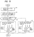
- Fig. 13 shows a second procedure to be executed by the gear change command determining device 43.
- the second procedure is effective in improving the operability of a vehicle equipped with an engine incapable of varying the air amount according to the change of air-fuel ratio. Although the contents of the second procedure are simpler than those of the first procedure, the operability improving effect of the second procedure is somewhat inferior to that of the first procedure.
- the gear change command determining device 43 receives the throttle valve opening data 131 in a step 1058, the vehicle speed data 137 and the air-fuel ratio command in a step 1059.
- the gear change command determining device 43 retrieves gear change data for non-lean-burn operation previously stored in the controller 40 according to the throttle valve opening data 131 and the vehicle speed data 137, and interpolates the gear change data to calculate the gear change command value 135 in a step 1062. If the air-fuel ratio command 141 specifies a lean air-fuel ratio in the step 1060, the gear change command determining device 43 retrieves the gear change data for lean-burn operation previously stored in the controller 40 according to the throttle valve opening data 131 and the vehicle speed data 137, and interpolates the gear change data to calculate the gear change command value 135 in a step 1061.
- Fig. 14 shows a third procedure to be executed by the gear change command determining device 43.
- the third procedure is effective in improving the operability of a vehicle equipped with an engine, similar to that described in connection with the first embodiment, capable of varying the air amount according to the change of the air-fuel ratio.
- the contents of the third procedure are simpler than those of the first and the second procedure. Since the variation of the output power of the engine or the engine torque due to the change of the air-fuel ratio is suppressed by the engine side, the operability improving effect of the third procedure is far superior to those of the first and the second procedure. For example, no trouble arises even if gear changing operation and air-fuel ratio changing operation are performed simultaneously.
- the gear change command determining device 43 receives the accelerator pedal position data 130 in a step 1063 and the vehicle speed data 137 in a step 1064, retrieves the gear change data for non-lean-burn operation previously stored in the controller 40, and interpolates the gear change data to calculate the gear change command value 135 in a step 1065. In this procedure, any gear change data for lean-burn operation need not be stored in the controller 40 or memory, because the variation of the output power of the engine due to the change of the air-fuel ratio is suppressed by the engine side.
- Fig. 15 shows a first procedure to be executed by the lockup determining device 44.
- the first procedure is effective in improving the operability of a vehicle equipped with an engine incapable of varying air amount according to the change of air-fuel ratio.
- the lockup determining device 44 receives the air-fuel ratio command 141 in a step 1066, the accelerator pedal position data 130 in a step 1067, the throttle valve opening data 131 in a step 1068 and the vehicle speed data 137 in a step 1069.
- the lockup determining device 44 retrieves lockup data for non-lean-burn operation previously stored in the controller 40 according to the throttle valve opening data 131 and the vehicle speed data 137, and interpolates the lockup data to calculate the lockup command value 136 in a step 1072. If the air-fuel ratio command 141 specifies a lean air-fuel ratio in the step 1070, the lockup determining device 44 retrieves the lockup data previously stored in the controller 40 according to the engine speed data 132 and the accelerator pedal position data 130, interpolates the lockup data to calculate an engine torque index in a step 1071.
- the lockup determining device 44 retrieves the lockup data for lean-burn operation previously stored in the controller 40 according to the engine torque index and the vehicle speed data 137, and then interpolates the lockup data to calculate the lockup command value 136 in a step 1073.
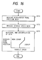
- Fig. 16 shows a second procedure to be executed by the lockup determining device 44.
- the second procedure is effective in improving the operability of a vehicle equipped with an engine, similar to that described in connection with the first embodiment, capable of varying air amount according to the change of the air-fuel ratio.
- the contents of the second procedure are simpler than those of the first procedure. Since the variation of the output power of the engine or the engine torque due to the change of the air-fuel ratio is suppressed by the engine side, the operability improving effect of the second procedure is far greater than that of the first procedure. For example, no trouble arises even if lockup operation and air-fuel ratio changing operation are performed simultaneously.
- the lockup determining device 44 receives the accelerator pedal position data 130 in a step 1074 and the vehicle speed data 137 in a step 1075, retrieves lockup data for non-lean-burn operation previously stored in the controller 40, and interpolates the lockup data to calculate the lockup command value 136 in a step 1076. Any data for lean-burn operation need not be stored in the controller 40 or memory, because the variation of the output power of the engine due to the change of the air-fuel ratio is suppressed by the engine side,.
- Fig. 17 shows a first procedure to be executed by the line pressure determining device 45.
- the first procedure is effective in improving the operability of a vehicle equipped with an engine incapable of varying air amount according to the change of the air-fuel ratio.
- the line pressure determining device 45 receives the air-fuel ratio command 141 in a step 1077, the accelerator pedal position data 130 in a step 1078 and the throttle valve opening data 131 in a step 1079.
- the line pressure determining device 45 retrieves line pressure data for non-lean-burn operation previously stored in the controller 40 according to the throttle valve opening data 131 and interpolates the line pressure data to calculate the line pressure command value 134 in a step 1082. If the air-fuel ratio command 141 specifies a lean air-fuel ratio in the step 1080, the line pressure determining device 45 retrieves data previously stored in the controller according to the engine speed data 132 and the accelerator pedal position data 130 and interpolates the data to calculate the engine torque index in a step 1081. Thereafter, the line pressure determining device 45 retrieves line pressure data for lean-burn operation previously stored in the controller according to the engine torque index and interpolates the line pressure data to calculate the line pressure command value 134 in a step 1083.
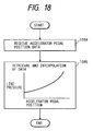
- Fig. 18 shows a second procedure to be executed by the line pressure determining device 45.
- the second procedure is effective in improving the operability of a vehicle equipped with an engine capable of varying the air amount according to the change of the air-fuel ratio.
- the contents of the second procedure is simpler than those of the first procedure.
- the line pressure determining device 45 receives the accelerator pedal position data 130 in a step 1084, retrieves line pressure data for non-lean-burn operation previously stored in the controller 40, and interpolates the line pressure data to calculate the line pressure command value 134 in a step 1085. Any data for lean-burn operation need not be stored, because the variation of the output power of the engine or the engine torque due to the change of the air-fuel ratio is suppressed by the engine side.
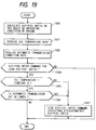
- Fig. 19 shows a procedure to be executed by the air-fuel ratio determining device 46.
- the air-fuel ratio determining device 46 receives the oil temperature data 133 representing the temperature of the oil of the automatic transmission and the automatic transmission condition data 142 in steps 1087 and 1088. If the air-fuel ratio command specifies a lean air-fuel ratio in a step 1089, and either of the following conditions (1) and (2) is satisfied in steps 1090 and 1091, an air-fuel ratio command specifying the stoichiometric air-fuel ratio is given to secure operability when the temperature of the automatic transmission is relatively low or the automatic transmission is out of order in a step 1092.
Abstract
Description
- The present invention relates to a method and an apparatus of controlling an engine power train including an engine which can operate on a lean air-fuel ratio and an automatic transmission connected to the engine for the vehicle.
- Active efforts have been made to develop an engine capable of operating on the lean air-fuel ratio larger than a stoichiometric air-fuel ratio to improve fuel consumption while suppressing harmful matters included in exhaust gas from the engine. A method of controlling an air-fuel ratio previously proposed in Japanese Application Laid-open No.52825/1978 changes the stoichiometric air-fuel ratio for the lean air-fuel ratio when the operating condition of the engine is within a predetermined range. This method increases the air-fuel ratio gradually after the load on the engine has increased beyond a predetermined value and decreases the air-fuel ratio gradually to an initial air-fuel ratio when the load decreases. Another method previously proposed in Japanese Application Laid-open No.10224/1976 increases the air-fuel ratio when the load on the engine is in a middle-load region, and controls the air-fuel ratio so that a fuel mixture of the stoichiometric air-fuel ratio or a rich air-fuel ratio is supplied to the engine when the load is in a low-load region or a high-load region, attaching importance to an output power of the engine.
- Since fuel amount is reduced below that of the stoichiometric air-fuel ratio during the operation on the lean air-fuel ratio, an engine torque decreases when the air-fuel ratio is increased with the opening of the throttle valve kept fixed. Since the catalyst for reducing the nitrogen oxide (NOx) concentration in the exhaust gas does not function effectively in a state where the air-fuel ratio is other than the stoichiometric air-fuel ratio, lean-burn operation is possible only at the air-fuel ratio that makes the NOx concentration of the exhaust gas lower than an allowable limit; that is, the transition of the air-fuel ratio between the stoichiometric air-fuel ratio and the air-fuel ratio for lean-burn operation must be completed as quickly as possible to satisfy the requirements of the exhaust gas.
- It is necessary to use an automatic transmission in combination with such an engine to secure easy driving. A gear changing operation of the automatic transmission is controlled according to a shift schedule stored in a memory of a controller. The shift schedule is designed on the basis of the opening of the throttle valve, which is an index of the engine torque, and the vehicle speed ("Motor Fan", San-ei Shobo, p. 29, Dec., 1990). The lockup schedule also is designed on the basis of the opening of the throttle valve and the vehicle speed. The line pressure is controlled according to the opening of the throttle valve to transmit the output power of the engine efficiently to the drive shaft.
- As mentioned above, the transition between the stoichiometric air-fuel ratio and the air-fuel ratio for lean-burn operation must be quickly completed. However, since the difference between a torque when the engine is operating on the stoichiometric air-fuel ratio and a torque when the engine is operating on the lean air-fuel ratio for lean-burn operation is about 30%, the vehicle may be shocked and a driver feels that the output power of the engine is insufficient during lean-burn operation if the air-fuel ratio is changed quickly.
- A first object of the present invention is to provide the engine power train control method and control apparatus capable of quickly changing the air-fuel ratio so as to meet the requirements of the exhaust gas without causing shocks and reducing the engine torque.
- Since the engine torque decreases if the opening of the throttle valve is kept fixed while the engine is operating on the lean air-fuel ratio, the timing of changing the speed of the automatic transmission, the timing of lockup and the setting of the line pressure become inappropriate, shocks due to changing the speed increases and operability is deteriorated.
- A second object of the present invention is to provide the engine power train control method and control apparatus capable of suppressing shocks due to changing the speed during lean-burn operation and of securing satisfactory operability.
- With the first object in view, the present invention carries out transition between the air-fuel ratio for lean-burn operation and the stoichiometric air-fuel ratio by varying an air-fuel ratio command value stepwise, and controls the air amount to change the air amount of the engine stepwise during transition between lean-burn operation and non-lean-burn operation.
- The air-fuel ratio command value is determined by retrieving data previously stored in the controller according to the basic fuel amount and the engine speed and interpolating the data. The data to be used depends on whether or not a current air-fuel ratio command value specifies the lean air-fuel ratio. When retrieving and interpolating the data, either the basic fuel amount or the engine speed, or both the basic fuel amount and the engine speed are rounded off to an optional place before retrieval and interpolation.
- In the transition between the air-fuel ratio for lean-burn operation and the stoichiometric air-fuel ratio, the air amount is controlled so that the fuel amount immediately before the transition and the fuel amount after the completion of the transition are equal to each other. When the engine is in lean-burn operation, the air amount is determined by retrieving data previously stored in the controller according to the position of the accelerator pedal which is pushed by the driver and the engine speed and interpolating the data. When the engine is in non-lean-burn operation, the air amount is determined only on the basis of the position of the accelerator pedal.
- In a fixed period following the stepwise change of the air-fuel ratio command value, the basic fuel amount is varied stepwise from a value determined on the basis of the air amount and the engine speed to a value determined on the basis of the position of the accelerator pedal and the engine speed. If the position of the accelerator pedal changes to a position outside a predetermined range during the fixed period, the basic fuel amount is determined on the basis of the air amount and the engine speed.
- With the second object in view, the present invention uses selectively a gear changing pattern for lean-burn operation and a gear changing pattern for non-lean-burn operation.
- The gear changing operation and the lockup operation are controlled according to the position of the accelerator pedal, the engine speed and the vehicle speed, and a line pressure of the automatic transmission is determined according to the position of the accelerator pedal and the engine speed while the engine is in lean-burn operation.
- Concerning a system of which the air amount changes according to the air-fuel ratio changing, the gear changing operation and the lockup operation are controlled according to the position of the accelerator pedal and vehicle speed, and the line pressure of the automatic transmission is determined according to the position of the accelerator pedal.
- When a temperature of an oil of the automatic transmission is lower than a predetermined temperature or when it is found that a part of the automatic transmission is out of order, the air-fuel ratio command value is inhibited from specifying the lean air-fuel ratio.
- Since the air-fuel ratio command value is varied stepwise during transition between the air-fuel ratio for lean-burn operation and the stoichiometric air-fuel ratio, the air-fuel ratio can be quickly changed. Since the air amount is varied stepwise, the variation of the engine torque due to the change of air-fuel ratio can be suppressed without delay.
- Since whether or not the current air-fuel ratio command value specifies the lean air-fuel ratio is taken into consideration when retrieving data for determining the air-fuel ratio, hunting between the lean air-fuel ratio and the non-lean air-fuel ratio due to the change of the basic fuel amount caused by the change of the air amount does not occur. Since either the basic fuel amount or the engine speed or both the basic fuel amount and the engine speed are rounded off to an optional place before the retrieval and interpolation of data, the air-fuel ratio can be varied smoothly in the range for lean-burn operation, so that the combustion in the engine can be stabilized.
- Since the air amount is controlled so that the fuel amount immediately before the transition between the air-fuel ratio for lean-burn operation and the stoichiometric air-fuel ratio and the fuel amount after the completion of the transition are equal to each other, the engine torque remains constant regardless of the transition of the air-fuel ratio.
- Since the air amount for lean-burn operation is determined by retrieving data previously stored in the controller according to the position of the accelerator pedal and the engine speed and interpolating the data, and the air amount for non-lean-burn operation is determined uniquely according to the position of the accelerator pedal, the engine torque can be properly corrected at every operating point of the engine during lean-burn operation, and the performance of the engine at every operating point is the same as that of the non-lean-burn engine, when the non-lean air-fuel ratio is specified.
- Since the basic fuel amount is changed stepwise from a value determined on the basis of the air amount and the engine speed to a value determined on the basis of the position of the accelerator pedal and the engine speed for a fixed period following the stepwise change of the air-fuel ratio command value, an optional fuel amount can be determined when the air amount is changed stepwise.
- Since the basic fuel amount is determined according to the air amount and the engine speed when the position of the accelerator pedal changes to a position outside a predetermined range in a fixed period, the fuel can be fed at an appropriate fuel amount when the accelerator pedal is released or when the accelerator pedal is operated for sharp acceleration.
- Since the gear changing operation is changed over between the gear changing pattern for lean-burn operation and the gear changing pattern for non-lean-burn operation, an optimum shift schedule can be designed according to the air-fuel ratio.
- Since the gear changing operation and the lockup operation are executed according to the position of the accelerator pedal, the engine speed, the vehicle speed and the line pressure of the automatic transmission is determined on the basis of the position of the accelerator pedal and the engine speed while the engine is in lean-burn operation, an optimum shift schedule, an optimum lockup schedule and an optimum line pressure can be determined even if the engine torque decreases during lean-burn operation.
- Since the gear changing operation and the lockup operation are executed according to the position of the accelerator pedal and the vehicle speed, and the line pressure of the automatic transmission is determined on the basis of the position of the accelerator pedal in the engine of which the air amount changes when the air-fuel ratio changes, the optimum shift schedule, the optimum lockup schedule and the optimum line pressure can be determined even when the opening of the throttle valve does not correspond uniquely to the engine torque due to the change of the air amount resulting from the change of air-fuel ratio.
- Since the air-fuel ratio command value is inhibited from specifying the lean air-fuel ratio when the temperature of the oil of the automatic transmission is lower than a predetermined temperature or when it is found that a part of the automatic transmission is out of order, the lean air-fuel ratio is not determined when the temperature of the oil of the automatic transmission is comparatively low or when the automatic transmission malfunctions.
- Fig. 1 is a block diagram showing a whole configuration of the invention.
- Fig. 2 is a graph showing relations of the engine torque, the NOx, and the air-fuel ratio.
- Fig. 3 is a signal block diagram for explaining a procedure of a first embodiment of the invention.
- Fig. 4 is a flow chart of a procedure to be executed by a normal basic fuel amount determining device.
- Fig. 5 is a flow chart of a procedure to be executed by a transient basic fuel amount determining device.
- Fig. 6 is a flow chart of a procedure to be executed by a fuel amount determining device.
- Fig. 7 is a flow chart of a procedure to be executed by an air-fuel ratio determining device.
- Fig. 8 is a flow chart of a procedure to be executed by an air amount determining device.
- Fig. 9 is a time diagram for explaining the effect of the first embodiment.
- Fig. 10 is a block diagram showing a whole configuration of a second embodiment of the invention.
- Fig. 11 is a signal block diagram for explaining a procedure to be executed by the second embodiment.
- Fig. 12 is a flow chart of a first procedure to be executed by a gear change command determining device.
- Fig 13 is a flow chart of a second procedure to be executed by the gear change command determining device.
- Fig. 14 is a flow chart of a third procedure to be executed by the gear change command determining device.
- Fig. 15 is a flow chart of a first procedure to be executed by a lockup determining device.
- Fig. 16 is a flow chart of a second procedure to be executed by the lockup determining device.
- Fig. 17 is a flow chart of a first procedure to be executed by a line pressure command determining device.
- Fig. 18 is a flow chart of a second procedure to be executed by the line pressure command determining device.
- Fig. 18 is a flow chart of a procedure to be executed by an air-fuel ratio determining device.
- Preferred embodiments of the present invention will be described hereinafter with reference to the accompanying drawings.
- Fig. 1 shows a whole configuration for illustrating a method in a first embodiment of the invention. The embodiment has a
controller 20 which controls anengine 12 provided at least with anair amount detector 13, an airamount controlling actuator 6, anengine speed detector 2 and afuel feed valve 29. Thecontroller 20 comprises a CPU (Central Processing Unit) 23, a ROM (Read-Only Memory) 24, a RAM (Random Access Memory) 25, I/O (Input-Output) ports 21, an A/D (Analog to Disital)converter 28, anaddress bus 26 and adata bus 27. Thecontroller 20 receives an acceleratorpedal position data 101, anair amount data 112 and anengine speed data 102, and executes procedures stored in theROM 24 to give instructions to the airamount controlling actuator 6 and thefuel feed valve 29. The present invention is featured by the procedures. - Fig. 2 shows relations between an engine torque and an air-fuel ratio and between a NOx (Nitrogen Oxide) and the air-fuel ratio. Since fuel amount is reduced below that of a stoichiometric air-fuel ratio during an operation on a lean air-fuel ratio, the engine torque decreases when the air-fuel ratio is increased with an opening of a throttle valve of the engine kept fixed. Since a catalyst for reducing the NOx concentration in an exhaust gas does not function effectively in a state where the air-fuel ratio is other than the stoichiometric air-fuel ratio, a lean-burn operation of the engine is possible only at the air-fuel ratio that makes the NOx concentration of the exhaust gas lower than an allowable limit; that is, the transition of the air-fuel ratio between the stoichiometric air-fuel ratio and the air-fuel ratio for the lean-burn operation must be completed as quickly as possible to satisfy the requirements of the exhaust gas.
- It is necessary to use an automatic transmission in combination with such an engine to secure easy driving. A gear changing operation of the automatic transmission is controlled according to a shift schedule stored in a memory of the
controller 20. - Fig. 3 is a signal block diagram for explaining the procedures of the first embodiment. A transient basic fuel
amount determining device 3 calculates a transient basicfuel amount data 103 for operation in an air-fuel ratio changing mode, using the acceleratorpedal position data 101 provided by an acceleratorpedal position detector 1 and theengine speed data 102 provided by theengine speed detector 2. A normal basic fuelamount determining device 4 calculates a normal basicfuel amount data 104 for operation in a normal mode, using theair amount data 112 provided by theair amount detector 13 and theengine speed data 102 provided by theengine speed detector 2. An air-fuelratio determining device 5 calculates an air-fuelratio command value 105 using theair amount data 112 and theengine speed data 102. A fuelamount determining device 11 determines afuel amount 111 using the transient basicfuel amount data 103, the normal basicfuel amount data 104, the air-fuelratio command value 105 and the acceleratorpedal position data 101, and gives a command to thefuel feed valve 29. An airamount determining device 7 calculates an airamount command value 109 using the acceleratorpedal position data 101, theengine speed data 102 and the air-fuelratio command value 105. The airamount determining device 7 controls the airamount controlling actuator 6 for controlling air amount fed to the engine. - Fig. 4 shows a procedure to be executed by the normal basic fuel
amount determining device 4. The normal basic fuelamount determining device 4 receives theair amount data 112 and theengine speed data 102, and then calculates the normal basicfuel amount data 104 by using following expression (1).
- Fig. 5 shows a procedure to be executed by the transient basic fuel
amount determining device 3. The transient basic fuelamount determining device 3 receives the acceleratorpedal position data 101 in astep 1004 and theengine speed data 102 in astep 102, retrieves data previously stored in thecontroller 20 according to the acceleratorpedal position data 101 and theengine speed data 102 and interpolates the data to calculate the transient basicfuel amount data 103 in astep 1006. The data stored in thecontroller 20 is a relation between theengine speed data 102, the acceleratorpedal position data 101 and the normal basicfuel amount data 104. This relation relates a state where the air-fuel ratio is for a non-lean fuel mixture and the airamount controlling actuator 6 is controlled by the acceleratorpedal position data 101. Therefore, the fuel amount immediately before the air-fuel ratio transition is equal to the fuel amount after the completion of the air-fuel ratio transition. - Fig. 6 shows a procedure to be executed by the fuel
amount determining device 11. The fuelamount determining device 11 receives the acceleratorpedal position data 101 in astep 1007, the air-fuel ratio command 105 in astep 1008, the transient basicfuel amount data 103 in astep 1009 and the normal basicfuel amount data 104 in astep 1010, and calculates an accelerator pedal operating speed data using the acceleratorpedal position data 101 in astep 1011. Suppose that a fixed period following the completion of change of the air-fuelratio command value 105 from specifying the lean air-fuel ratio to specifying the non-lean air-fuel ratio or from specifying the non-lean air-fuel ratio to specifying the lean air-fuel ratio is an air-fuel ratio transition period. Then, insteps 1012 to 1014, if
and
in the air-fuel ratio transition period, in astep 1015,
If not, in astep 1016,
In astep 1017, if the air-fuelratio command value 105 specifies a non-lean air-fuel ratio after thestep 1015, in astep 1018,
is calculated. Thefuel amount data 111 is calculated by using the following expression in astep 1019.
- The correction value is an incremental air-fuel ratio for acceleration. The fuel amount is thus determined, so that the fuel amount during the air-fuel ratio transition is substantially equal to the fuel amount immediately before the air-fuel ratio transition and the variation of the engine torque is suppressed.
- Fig. 7 shows a procedure to be executed by the air-fuel
ratio determining device 5. The air-fuelratio determining device 5 receives theair amount data 112 in astep 1020 and theengine speed data 102 in astep 1021, and omits, raises or rounds off the received data to an optional place insteps ratio command value 105 calculated in the preceding calculation cycle specifies the lean air-fuel ratio in astep 1024, data for lean-burn operation previously stored in thecontroller 20 is retrieved according to the rounded air amount data and the rounded engine speed data, and the data is interpolated to calculate an air-fuelratio command value 105 in astep 1025. If the air-fuelratio command value 105 calculated in the preceding calculation cycle specifies a non-lean air-fuel ratio in thestep 1024, data for non-lean-burn operation previously stored in the controller is retrieved according to the rounded air amount data and the rounded engine speed data, and the data is interpolated to calculate an air-fuelratio command value 105 in astep 1026. - Fig. 8 shows a procedure to be executed by the air
amount controlling actuator 6. The airamount controlling actuator 6 receives the air-fuel ratio command 105 in astep 1027, the acceleratorpedal position data 101 in astep 1028 and theengine speed data 102 in astep 1029. If the air-fuelratio command value 105 specifies the lean air-fuel ratio in astep 1030, air amount command data for lean-burn operation previously stored in thecontroller 20 is retrieved according to the acceleratorpedal position data 101 and theengine speed data 102, and the air amount command data is interpolated to determine an airamount command value 109 in astep 1031. If the air-fuelratio command value 105 specifies the non-lean air-fuel ratio in thestep 1030, the air amount command data for non-lean-burn operation previously stored in thecontroller 20 is retrieved according to the acceleratorpedal position data 101, and the air amount command data is interpolated to determine the airamount command value 109 in astep 1032. Thus, the fuel amount during the air-fuel ratio transition equals the fuel amount after the completion of the air-fuel ratio transition, so that the variation of the engine torque is suppressed. - Fig. 9 shows the effects of the first embodiment. When the air-fuel ratio command specifying the stoichiometric air-fuel ratio is changed stepwise to the air-fuel ratio command specifying the lean air-fuel ratio with the accelerator pedal position fixed, the air amount controlling actuator operates with a short time lag in an opening direction and, consequently, the air amount increases. Since the air-fuel ratio increases, the basic fuel amount is incremented according to the expression (6) above mentioned and the fuel amount is reduced according to the expression (7) above mentioned, the output power of the engine and the engine torque are caused to change scarcely by the air-fuel ratio transition. When the air-fuel ratio command changes stepwise from the air-fuel ratio command specifying the lean air-fuel ratio to the air-fuel ratio command specifying the stoichiometric air-fuel ratio, the air amount controlling actuator operates with a short time lag in a closing direction and, consequently, the air amount is reduced. Since the air-fuel ratio decreases, the basic fuel amount is reduced according to the expression (4) above mentioned and the fuel amount is increased according to the expression (7) above mentioned, the output power of the engine and the engine torque are caused to change scarcely by the air-fuel ratio transition. Therefore, the driver is able to drive the vehicle without being aware of the change of the air-fuel ratio at all.
- Fig. 10 shows a whole configuration for illustrating a method in a second embodiment according to the invention. The embodiment has an
automatic transmission controller 40, an acceleratorpedal position detector 30, a throttlevalve opening detector 31, anengine speed detector 32, anoil temperature detector 33, avehicle speed detector 37, a linepressure controlling actuator 34, a gearchange controlling actuator 35, alockup controlling actuator 36 and anengine controller 41. Theautomatic transmission controller 40 and theengine controller 41 are microcomputers and control anengine 38 and anautomatic transmission 39. Theautomatic transmission controller 40 receives an acceleratorpedal position data 130, a throttlevalve opening data 131, anengine speed data 132, anoil temperature data 133, avehicle speed data 137 and an air-fuelratio command value 141 and gives aline pressure command 134, agear change command 135, alockup command 136, theoil temperature data 133 and an automatictransmission condition data 142. The air-fuelratio command value 141 is provided by theengine controller 41. Theoil temperature data 133 and the automatictransmission condition data 142 are obtained through the examination of the operating condition of theautomatic transmission 39 to theengine controller 41. It is possible that theoil temperature data 133 may be applied directly to theengine controller 41 instead of given through theautomatic transmission controller 40 to theengine controller 41. - Fig. 11 shows a procedure to be executed by the second embodiment. The
automatic transmission controller 40 comprises a gear changecommand determining device 43, a lockupcommand determining device 44 and a linepressure determining device 45. The gear changecommand determining device 43 determines a gear change ratio on the basis of the acceleratorpedal position data 130 provided by the acceleratorpedal position detector 30, the throttlevalve opening data 131 provided by the throttlevalve opening detector 31, theengine speed data 132 provided by theengine speed detector 32 and thevehicle speed data 137 provided by thevehicle speed detector 37, and provides thegear change command 135. Thelockup determining device 44 decides whether or not lockup is to be performed on the basis of the acceleratorpedal position data 130, the throttlevalve opening data 131, theengine speed data 132 and thevehicle speed data 137, and provides thelockup command 136. The linepressure determining device 45 determines a line pressure on the basis of the acceleratorpedal position data 130, the throttlevalve opening data 131 and theengine speed data 132, and provides theline pressure command 134. An air-fuelratio determining device 46 of theengine controller 41 determines an air-fuel ratio according to the condition of theengine 38, determines a final air-fuel ratio on the basis of theoil temperature data 133 provided by theoil temperature detector 33 and the automatictransmission condition data 142 provided by an automatictransmission monitoring device 42, and then gives the air-fuel ratio command 141 to theautomatic transmission controller 40. - Fig. 12 shows a first procedure to be executed by the gear change
command determining device 43. The first procedure is effective in improving the operability of a vehicle equipped with an engine incapable of varying the air amount according to the change of the air-fuel ratio. The gear changecommand determining device 43 receives the air-fuel ratio command 141 in astep 1050, the acceleratorpedal position data 130 in astep 1051, the throttlevalve opening data 131 in astep 1052 and thevehicle speed data 137 in astep 1053. If the air-fuel ratio command 141 specifies the non-lean air-fuel ratio in astep 1054, the gear changecommand determining device 43 retrieves the gear changing data for non-lean-burn operation previously stored in thecontroller 40 according to the throttlevalve opening data 131 and thevehicle speed data 137, and interpolates the gear changing data to calculate the gearchange command value 135 in astep 1056. If the air-fuel ratio command 141 specifies the lean air-fuel ratio in thestep 1054, the gear changecommand determining device 43 retrieves data previously stored in thecontroller 40 according to theengine speed data 132 and the acceleratorpedal position data 130, and interpolates the data to calculate an engine torque index in astep 1055. Thereafter the gear changecommand determining device 43 retrieves gear change data for lean-burn operation previously stored in thecontroller 40 according to the engine torque index and thevehicle speed data 137, and interpolates the gear change data to calculate the gearchange command value 135 in astep 1057. - Fig. 13 shows a second procedure to be executed by the gear change
command determining device 43. The second procedure is effective in improving the operability of a vehicle equipped with an engine incapable of varying the air amount according to the change of air-fuel ratio. Although the contents of the second procedure are simpler than those of the first procedure, the operability improving effect of the second procedure is somewhat inferior to that of the first procedure. The gear changecommand determining device 43 receives the throttlevalve opening data 131 in astep 1058, thevehicle speed data 137 and the air-fuel ratio command in astep 1059. If the air-fuel ratio command 141 specifies a non-lean air-fuel ratio in astep 1060, the gear changecommand determining device 43 retrieves gear change data for non-lean-burn operation previously stored in thecontroller 40 according to the throttlevalve opening data 131 and thevehicle speed data 137, and interpolates the gear change data to calculate the gearchange command value 135 in astep 1062. If the air-fuel ratio command 141 specifies a lean air-fuel ratio in thestep 1060, the gear changecommand determining device 43 retrieves the gear change data for lean-burn operation previously stored in thecontroller 40 according to the throttlevalve opening data 131 and thevehicle speed data 137, and interpolates the gear change data to calculate the gearchange command value 135 in astep 1061. - Fig. 14 shows a third procedure to be executed by the gear change
command determining device 43. The third procedure is effective in improving the operability of a vehicle equipped with an engine, similar to that described in connection with the first embodiment, capable of varying the air amount according to the change of the air-fuel ratio. The contents of the third procedure are simpler than those of the first and the second procedure. Since the variation of the output power of the engine or the engine torque due to the change of the air-fuel ratio is suppressed by the engine side, the operability improving effect of the third procedure is far superior to those of the first and the second procedure. For example, no trouble arises even if gear changing operation and air-fuel ratio changing operation are performed simultaneously. The gear changecommand determining device 43 receives the acceleratorpedal position data 130 in astep 1063 and thevehicle speed data 137 in astep 1064, retrieves the gear change data for non-lean-burn operation previously stored in thecontroller 40, and interpolates the gear change data to calculate the gearchange command value 135 in astep 1065. In this procedure, any gear change data for lean-burn operation need not be stored in thecontroller 40 or memory, because the variation of the output power of the engine due to the change of the air-fuel ratio is suppressed by the engine side. - Fig. 15 shows a first procedure to be executed by the
lockup determining device 44. The first procedure is effective in improving the operability of a vehicle equipped with an engine incapable of varying air amount according to the change of air-fuel ratio. Thelockup determining device 44 receives the air-fuel ratio command 141 in astep 1066, the acceleratorpedal position data 130 in astep 1067, the throttlevalve opening data 131 in astep 1068 and thevehicle speed data 137 in astep 1069. If the air-fuel ratio command 144 specifies the non-lean air-fuel ratio in astep 1070, thelockup determining device 44 retrieves lockup data for non-lean-burn operation previously stored in thecontroller 40 according to the throttlevalve opening data 131 and thevehicle speed data 137, and interpolates the lockup data to calculate thelockup command value 136 in astep 1072. If the air-fuel ratio command 141 specifies a lean air-fuel ratio in thestep 1070, thelockup determining device 44 retrieves the lockup data previously stored in thecontroller 40 according to theengine speed data 132 and the acceleratorpedal position data 130, interpolates the lockup data to calculate an engine torque index in astep 1071. Thereafter, thelockup determining device 44 retrieves the lockup data for lean-burn operation previously stored in thecontroller 40 according to the engine torque index and thevehicle speed data 137, and then interpolates the lockup data to calculate thelockup command value 136 in astep 1073. - Fig. 16 shows a second procedure to be executed by the
lockup determining device 44. The second procedure is effective in improving the operability of a vehicle equipped with an engine, similar to that described in connection with the first embodiment, capable of varying air amount according to the change of the air-fuel ratio. The contents of the second procedure are simpler than those of the first procedure. Since the variation of the output power of the engine or the engine torque due to the change of the air-fuel ratio is suppressed by the engine side, the operability improving effect of the second procedure is far greater than that of the first procedure. For example, no trouble arises even if lockup operation and air-fuel ratio changing operation are performed simultaneously. Thelockup determining device 44 receives the acceleratorpedal position data 130 in astep 1074 and thevehicle speed data 137 in astep 1075, retrieves lockup data for non-lean-burn operation previously stored in thecontroller 40, and interpolates the lockup data to calculate thelockup command value 136 in astep 1076. Any data for lean-burn operation need not be stored in thecontroller 40 or memory, because the variation of the output power of the engine due to the change of the air-fuel ratio is suppressed by the engine side,. - Fig. 17 shows a first procedure to be executed by the line
pressure determining device 45. The first procedure is effective in improving the operability of a vehicle equipped with an engine incapable of varying air amount according to the change of the air-fuel ratio. The linepressure determining device 45 receives the air-fuel ratio command 141 in astep 1077, the acceleratorpedal position data 130 in astep 1078 and the throttlevalve opening data 131 in astep 1079. If the air-fuel ratio command 141 specifies the non-lean air-fuel ratio in astep 1080, the linepressure determining device 45 retrieves line pressure data for non-lean-burn operation previously stored in thecontroller 40 according to the throttlevalve opening data 131 and interpolates the line pressure data to calculate the linepressure command value 134 in astep 1082. If the air-fuel ratio command 141 specifies a lean air-fuel ratio in thestep 1080, the linepressure determining device 45 retrieves data previously stored in the controller according to theengine speed data 132 and the acceleratorpedal position data 130 and interpolates the data to calculate the engine torque index in astep 1081. Thereafter, the linepressure determining device 45 retrieves line pressure data for lean-burn operation previously stored in the controller according to the engine torque index and interpolates the line pressure data to calculate the linepressure command value 134 in astep 1083. - Fig. 18 shows a second procedure to be executed by the line
pressure determining device 45. The second procedure is effective in improving the operability of a vehicle equipped with an engine capable of varying the air amount according to the change of the air-fuel ratio. The contents of the second procedure is simpler than those of the first procedure. The linepressure determining device 45 receives the acceleratorpedal position data 130 in astep 1084, retrieves line pressure data for non-lean-burn operation previously stored in thecontroller 40, and interpolates the line pressure data to calculate the linepressure command value 134 in astep 1085. Any data for lean-burn operation need not be stored, because the variation of the output power of the engine or the engine torque due to the change of the air-fuel ratio is suppressed by the engine side. - Fig. 19 shows a procedure to be executed by the air-fuel
ratio determining device 46. After calculating the air-fuel ratio on the basis of the operating condition of the engine in astep 1086, the air-fuelratio determining device 46 receives theoil temperature data 133 representing the temperature of the oil of the automatic transmission and the automatictransmission condition data 142 insteps step 1089, and either of the following conditions (1) and (2) is satisfied insteps step 1092. - (1)

- (2) Part of the automatic transmission is out of order
- As is apparent from the foregoing description, the present invention has the following effects.
- 1. Since the air-fuel ratio command value is varied stepwise during transition between the air-fuel ratio for lean-burn operation and the stoichiometric air-fuel ratio, the air-fuel ratio can be quickly changed. Since the air amount fed to the engine is varied stepwise, the variation of the engine torque due to the change of air-fuel ratio can be suppressed without delay.
- 2. Since whether or not the current air-fuel ratio command value specifies the lean air-fuel ratio is taken into consideration when retrieving data for determining the air-fuel ratio, hunting between the lean air-fuel ratio and the non-lean air-fuel ratio due to the change of the basic fuel amount fed to the engine caused by the change of the air amount does not occur.
- 3. Since either the basic fuel amount or the engine speed or both the basic fuel amount and the engine speed are rounded off to an optional place before the retrieval and interpolation of data, the air-fuel ratio can be varied smoothly in the range for lean-burn operation, so that the combustion in the engine can be stabilized.
- 4. Since the air amount is controlled so that the fuel amount immediately before the transition between the air-fuel ratio for lean-burn operation and the stoichiometric air-fuel ratio equals- the fuel amount after the completion of the transition, the engine torque remains constant regardless of the transition of the air-fuel ratio.
- 5. Since the air amount for lean-burn operation is determined by retrieving data previously stored in the controller according to the position of the accelerator pedal and the engine speed and interpolating the data and air amount for non-lean-burn operation is determined uniquely according to the position of the accelerator pedal, the engine torque can be properly corrected at every operating point of the engine during lean-burn operation. The performance of the engine at every operating point is the same as that of an non-lean-burn engine, when the non-lean air-fuel ratio is specified.
- 6. Since the basic fuel amount is changed stepwise from the value determined on the basis of the air amount and the engine speed to the value determined on the basis of the position of the accelerator pedal and the engine speed for a fixed period following the stepwise change of the air-fuel ratio command value, the optional fuel amount can be determined when the air amount is changed stepwise. The fuel can be fed at the appropriate fuel amount when the accelerator pedal is released or when the accelerator pedal is operated for sharp acceleration, because the basic fuel amount is determined according to the air amount and the engine speed when the position of the accelerator pedal changes to the position outside the predetermined range in the fixed period.
- 7. An optimum shift schedule can be designed according to air-fuel ratio, because the gear changing operation is changed over between the gear changing pattern for lean-burn operation and the gear changing pattern for non-lean-burn operation.
- 8. The optimum shift schedule, the optimum lockup schedule and the optimum line pressure can the determined even if the engine torque decreases during lean-burn operation, because the gear changing operation and the lockup operation are executed according to the position of the accelerator pedal, the engine speed and the vehicle speed, and the line pressure of the automatic transmission is determined on the basis of the position of the accelerator pedal and the engine speed while the engine is in lean-burn operation.
- 9. The optimum shift schedule, the optimum lockup schedule and the optimum line pressure can be determined even when the opening of the throttle valve does not correspond uniquely to the engine torque due to the variation of the air amount resulting from the change of the air-fuel ratio, because the gear changing operation and the lockup operation are executed according to the position of the accelerator pedal and the vehicle speed, and the line pressure of the automatic transmission is determined on the basis of the position of the accelerator pedal in the engine which changes the air amount when the air-fuel ratio is changed.
Claims (50)
- An engine power train control method for a vehicle having an engine and an automatic transmission, comprising the step of:
determining a fuel amount fed to the engine according to a position of an accelerator pedal of the vehicle and an engine speed of the engine for a fixed period during transition between a first air-fuel ratio for lean-burn operation and a second air-fuel ratio for non-lean-burn operation of the engine. - An engine power train control method according to claim 1, further comprising the step of:
inhibiting to determine said fuel amount when the position of the accelerator pedal is nearer to a free position than a predetermined position during said fixed period. - An engine power train control method according to claim 1, further comprising the step of:
inhibiting to determine said fuel amount when the position of the accelerator pedal is farther from a free position than a predetermined position during said fixed period. - An engine power train control method according to claim 1, further comprising the step of:
inhibiting to determine said fuel amount when an operating speed of the accelerator pedal is lower than a predetermined value during said fixed period. - An engine power train control method according to claim 1, further comprising the step of:
inhibiting to determine said fuel amount when an operating speed of the accelerator pedal is higher than a predetermined value during said fixed period. - An engine power train control method for a vehicle having an engine and an automatic transmission, comprising the step of:
determining at least one of a first air amount fed to the engine and a first fuel amount fed to the engine after a completion of a transition of an air-fuel ratio based on at least one of a second air amount fed to the engine and a second fuel amount fed to the engine immediately before the transition of the air-fuel ratio during transition between a first air-fuel ratio for lean-burn operation and a second air-fuel ratio for non-lean-burn operation of the engine. - An engine power train control method according to claim 6, wherein said first air amount and said first fuel amount are determined so that the second fuel amount immediately before the transition of the air-fuel ratio is equal to the first fuel amount after the completion of the transition of the air-fuel ratio during transition between a first air-fuel ratio for lean-burn operation and a second air-fuel ratio for non-lean-burn operation of the engine.
- An engine power train control method for a vehicle having an engine and an automatic transmission, comprising the step of:
changing a command value specifying an air-fuel ratio of the engine stepwise during transition between a first air-fuel ratio for lean-burn operation and a second air-fuel ratio for non-lean-burn operation. - An engine power train control method according to claim 8, further comprising the step of:
changing basic fuel amount fed to the engine stepwise from a first value determined according to an air amount fed to the engine and an engine speed of the engine to a second value determined according to a position of an accelerator pedal of the vehicle and the engine speed during transition between a first air-fuel ratio for lean-burn operation and a second air-fuel ratio for non-lean-burn operation. - An engine power train control method according to claim 8, further comprising the step of:
changing an air amount command value given to an air amount controlling an actuator for controlling the air amount fed to the engine stepwise and simultaneously said command value specifying an air-fuel ratio stepwise during transition between a first air-fuel ratio for lean-burn operation and a second air-fuel ratio for non-lean-burn operation. - An engine power train control method according to claim 10, wherein said air amount command value is given by retrieving data previously stored in a controller by using the position of the accelerator pedal and the engine speed when the air-fuel ratio command specifies a first air-fuel ratio for lean-burn operation, or according to a position of an accelerator pedal when the air-fuel ratio command specifies a second air-fuel ratio for a non-lean-burn operation.
- An engine power train control method for a vehicle having an engine and an automatic transmission, comprising the steps of:
determining a basic fuel amount according to an air amount fed to the engine and an engine speed of the engine; and
determining an air-fuel ratio of the engine by retrieving data previously stored in a controller of the vehicle according to a basic fuel amount and the engine speed and interpolating the data. - An engine power train control method according to claim 12, further comprising the step of:
rounding off at least one of the basic fuel amount and the engine speed when determining the air-fuel ratio by retrieving the data previously stored in the controller according to the basic fuel amount and the engine speed and interpolating the data. - An engine power train control method according to claim 12, wherein said air-fuel ratio is determined so as to be smoothly changeable by retrieving the data previously stored in the controller and interpolating the data.
- An engine power train control method for a vehicle having an engine and an automatic transmission, comprising the step of:
determining a control value controlling the engine power train according to a position of an accelerator pedal of the vehicle, an engine speed of the engine and a vehicle speed while the engine is operated in lean-burn operation. - An engine power train control method according to claim 15, wherein said control value is a timing of a gear change of the automatic transmission.
- An engine power train control method according to claim 15, wherein said control value is a timing of a lockup operation of the automatic transmission.
- An engine power train control method according to claim 15, wherein said control value is a line pressure of the automatic transmission.
- An engine power train control method for a vehicle having an engine and an automatictransmission, comprising the steps of:
changing an air amount fed to the engine according to a transition of an air-fuel ratio; and
determining a control value controlling the engine power train according to a position of an accelerator pedal of the vehicle and a vehicle speed. - An engine power train control method according to claim 19, wherein said control value is a timing of a gear change of the automatic transmission.
- An engine power train control method according to claim 19, wherein said control value is a timing of lockup operation of the automatic transmission.
- An engine power train control method according to claim 19, wherein said control value is a line pressure of the automatic transmission.
- An engine power train control method for a vehicle having an engine and an automatic transmission, comprising the step of:
inhibiting an air-fuel ratio command value from specifying an air-fuel ratio for lean-burn operation of the engine while a condition of the automatic transmission is abnormal. - An engine power train control method according to claim 23, wherein said abnormal condition of the automatic transmission is that a temperature of an oil of the automatic transmission is lower than a predetermined temperature.
- An engine power train control method according to claim 23, wherein said abnormal condition of the automatic transmission is that it is decided that part of the automatic transmission is out of order.
- An engine power train control apparatus for a vehicle having an engine and an automatic transmission, comprising:
determining means for determining a fuel amount fed to the engine according to a position of an accelerator pedal of the vehicle and an engine speed of the engine for a fixed period during transition between a first air-fuel ratio for lean-burn operation and a second air-fuel ratio for non-lean-burn operation of the engine. - An engine power train control apparatus according to claim 26, further comprising:
inhibiting means for inhibiting to determine said fuel amount when the position of the accelerator pedal is nearer to a free position than a predetermined position during said fixed period. - An engine power train control apparatus according to claim 26, further comprising:
inhibiting means for inhibiting to determine said fuel amount when the position of the accelerator pedal is farther from a free position than a predetermined position during said fixed period. - An engine power train control apparatus according to claim 26, further comprising:
inhibiting means for inhibiting to determine said fuel amount when an operating speed of the accelerator pedal is lower than a predetermined value during said fixed period. - An engine power train control apparatus according to claim 26, further comprising:
inhibiting means for inhibiting to determine said fuel amount when an operating speed of the accelerator pedal is higher than a predetermined value during said fixed period. - An engine power train control apparatus for a vehicle having an engine and an automatic transmission, comprising:
determining means for determining at least one of a first air amount fed to an engine of the vehicle and a first fuel amount fed to the engine after a completion of a transition of an air-fuel ratio based on at least one of a second air amount fed to the engine and a second fuel amount fed to the engine immediately before the transition of the air-fuel ratio during transition between a first air-fuel ratio for lean-burn operation and a second air-fuel ratio for non-lean-burn operation of the engine. - An engine power train control apparatus according to claim 31, wherein said determining means determines the first air amount and the first fuel amount so that the second fuel amount immediately before the transition of the air-fuel ratio is equal to the first fuel amount after the completion of the transition of the air-fuel ratio during transition between a first air-fuel ratio for lean-burn operation and a second air-fuel ratio for non-lean-burn operation of the engine.
- An engine power train control apparatus for a vehicle having an engine and an automatic transmission, comprising:
commanding means for changing a command value specifying an air-fuel ratio of the engine stepwise during transition between a first air-fuel ratio for lean-burn operation and a second air-fuel ratio for non-lean-burn operation. - An engine power train control apparatus according to claim 33, wherein said commanding means changes a basic fuel amount fed to the engine stepwise from a first value determined according to an air amount fed to the engine and an engine speed of the engine to a second value determined according to a position of an accelerator pedal of the vehicle and the engine speed during transition between a first air-fuel ratio for lean-burn operation and a second air-fuel ratio for non-lean-burn operation.
- An engine power train control apparatus according to claim 33, wherein said commanding means changes an air amount command value given to an air amount controlling an actuator for controlling the air amount fed to the engine stepwise and simultaneously said command value specifying an air-fuel ratio stepwise during transition between a first air-fuel ratio for lean-burn operation and a second air-fuel ratio for non-lean-burn operation.
- An engine power train control apparatus according to claim 35, wherein said air amount command value is given by retrieving data previously stored in a controller by using a position of an accelerator pedal and the engine speed when the air-fuel ratio command specifies a first air-fuel ratio for lean-burn operation, or according to the position of the accelerator pedal when the air-fuel ratio command specifies a second air-fuel ratio for a non-lean-burn operation.
- An engine power train control apparatus for a vehicle having an engine and an automatic transmission, comprising:
first determining means for determining a basic fuel amount according to an air amount fed to the engine and an engine speed of the engine; and
second determining means for determining an air-fuel ratio of the engine by retrieving data previously stored in a controller of the vehicle according to a basic fuel amount and the engine speed and interpolating the data. - An engine power train control apparatus according to claim 37, wherein said second determining means rounds off at least one of the basic fuel amount and the engine speed when determining the air-fuel ratio by retrieving the data previously stored in the controller according to the basic fuel amount and the engine speed and interpolating the data.
- An engine power train control apparatus according to claim 37, wherein said second determining means determines the air-fuel ratio so as to be smoothly changeable by retrieving the data previously stored in the controller and interpolating the data.
- An engine power train control apparatus for a vehicle having an engine and an automatic transmission, comprising:
determining means for determining a control value controlling the engine power train according to a position of an accelerator pedal of the vehicle, an engine speed of the engine and a vehicle speed while the engine is operated in lean-burn operation. - An engine power train control apparatus according to claim 40, wherein said control value is a timing of a gear change of the automatic transmission.
- An engine power train control apparatus according to claim 40, wherein said control value is a timing of a lockup operation of the automatic transmission.
- An engine power train control apparatus according to claim 40, wherein said control value is a line pressure of the automatic transmission.
- An engine power train control apparatus for a vehicle having an engine and an automatictransmission, comprising:
determining means for changing an air amount fed to the engine according to a transition of an air-fuel ratio and determining a control value controlling the engine power train according to a position of an accelerator pedal of the vehicle and a vehicle speed. - An engine power train control apparatus according to claim 44, wherein said control value is a timing of a gear change of the automatic transmission.
- An engine power train control apparatus according to claim 44, wherein said control value is a timing of lockup operation of the automatic transmission.
- An engine power train control apparatus according to claim 44, wherein said control value is a line pressure of the automatic transmission.
- An engine power train control apparatus for a vehicle having an engine and an automatic transmission, comprising:
inhibiting means for inhibiting an air-fuel ratio command value from specifying an air-fuel ratio for lean-burn operation of the engine while a condition of the automatic transmission is abnormal. - An engine power train control apparatus according to claim 48, wherein said abnormal condition of the automatic transmission is that a temperature of an oil of the automatic transmission is lower than a predetermined temperature.
- An engine power train control apparatus according to claim 48, wherein said abnormal condition of the automatic transmission is that it is decided that part of the automatic transmission is out of order.
Priority Applications (2)
| Application Number | Priority Date | Filing Date | Title |
|---|---|---|---|
| EP01114586A EP1149999A3 (en) | 1994-07-25 | 1995-07-17 | Engine power train control method and control apparatus for a vehicle |
| EP98104850A EP0853190B1 (en) | 1994-07-25 | 1995-07-17 | Engine power train control method and control apparatus for a vehicle |
Applications Claiming Priority (2)
| Application Number | Priority Date | Filing Date | Title |
|---|---|---|---|
| JP6172292A JPH0835438A (en) | 1994-07-25 | 1994-07-25 | Method for controlling engine power train |
| JP172292/94 | 1994-07-25 |
Related Child Applications (2)
| Application Number | Title | Priority Date | Filing Date |
|---|---|---|---|
| EP98104850A Division EP0853190B1 (en) | 1994-07-25 | 1995-07-17 | Engine power train control method and control apparatus for a vehicle |
| EP01114586A Division EP1149999A3 (en) | 1994-07-25 | 1995-07-17 | Engine power train control method and control apparatus for a vehicle |
Publications (2)
| Publication Number | Publication Date |
|---|---|
| EP0697510A2 true EP0697510A2 (en) | 1996-02-21 |
| EP0697510A3 EP0697510A3 (en) | 1997-04-09 |
Family
ID=15939230
Family Applications (3)
| Application Number | Title | Priority Date | Filing Date |
|---|---|---|---|
| EP95304955A Withdrawn EP0697510A3 (en) | 1994-07-25 | 1995-07-17 | Power train control method and control apparatus for a vehicle |
| EP98104850A Expired - Lifetime EP0853190B1 (en) | 1994-07-25 | 1995-07-17 | Engine power train control method and control apparatus for a vehicle |
| EP01114586A Withdrawn EP1149999A3 (en) | 1994-07-25 | 1995-07-17 | Engine power train control method and control apparatus for a vehicle |
Family Applications After (2)
| Application Number | Title | Priority Date | Filing Date |
|---|---|---|---|
| EP98104850A Expired - Lifetime EP0853190B1 (en) | 1994-07-25 | 1995-07-17 | Engine power train control method and control apparatus for a vehicle |
| EP01114586A Withdrawn EP1149999A3 (en) | 1994-07-25 | 1995-07-17 | Engine power train control method and control apparatus for a vehicle |
Country Status (5)
| Country | Link |
|---|---|
| US (2) | US5642709A (en) |
| EP (3) | EP0697510A3 (en) |
| JP (1) | JPH0835438A (en) |
| KR (1) | KR100397661B1 (en) |
| DE (1) | DE69531796T2 (en) |
Cited By (3)
| Publication number | Priority date | Publication date | Assignee | Title |
|---|---|---|---|---|
| EP0849461A2 (en) * | 1996-12-19 | 1998-06-24 | Toyota Jidosha Kabushiki Kaisha | Combustion controller for internal combustion engines |
| EP0849458A2 (en) * | 1996-12-18 | 1998-06-24 | Toyota Jidosha Kabushiki Kaisha | Apparatus and method for controlling combustion in internal combustion engines |
| EP0888921A2 (en) * | 1997-07-01 | 1999-01-07 | Siemens Aktiengesellschaft | Control for the drive unit of a motor vehicle |
Families Citing this family (17)
| Publication number | Priority date | Publication date | Assignee | Title |
|---|---|---|---|---|
| EP0687809B1 (en) * | 1994-06-17 | 2001-08-29 | Hitachi, Ltd. | An output torque control apparatus and method for an internal combustion engine |
| JPH0835438A (en) * | 1994-07-25 | 1996-02-06 | Hitachi Ltd | Method for controlling engine power train |
| JP2923849B2 (en) * | 1996-02-21 | 1999-07-26 | 本田技研工業株式会社 | Air-fuel ratio control device for internal combustion engine |
| US5931138A (en) * | 1996-02-23 | 1999-08-03 | Nissan Motor Co., Ltd. | Engine torque control apparatus |
| JP3605221B2 (en) * | 1996-03-19 | 2004-12-22 | 株式会社日立製作所 | Control device for internal combustion engine |
| FR2766872B1 (en) * | 1997-08-01 | 1999-10-15 | Renault | METHOD FOR CORRECTING THE TORQUE IMPACT OF AN INTERNAL COMBUSTION ENGINE |
| US6308683B1 (en) * | 2000-01-06 | 2001-10-30 | Ford Global Tech, Inc. | Cylinder air charge estimation assembly |
| US6352490B1 (en) | 2000-02-04 | 2002-03-05 | Ford Global Technologies, Inc. | Optimization method for a lean capable multi-mode engine |
| US6487850B1 (en) * | 2000-03-17 | 2002-12-03 | Ford Global Technologies, Inc. | Method for improved engine control |
| US6860100B1 (en) | 2000-03-17 | 2005-03-01 | Ford Global Technologies, Llc | Degradation detection method for an engine having a NOx sensor |
| DE10017545A1 (en) * | 2000-04-08 | 2001-10-11 | Bosch Gmbh Robert | Method for operating an internal combustion engine |
| US6390948B1 (en) | 2000-07-12 | 2002-05-21 | Ford Global Technologies, Inc. | Transmission ratio change control during mode transitions in lean burn/DISI engines |
| US6349700B1 (en) | 2000-08-11 | 2002-02-26 | Ford Global Technologies, Inc. | Engine/vehicle speed control for direct injection spark ignition engine applications |
| US7010417B2 (en) * | 2002-12-03 | 2006-03-07 | Cummins, Inc. | System and method for determining maximum available engine torque |
| US7562649B2 (en) * | 2007-07-05 | 2009-07-21 | Southwest Research Institute | Combustion control system based on in-cylinder condition |
| DE102018122963A1 (en) * | 2018-09-19 | 2020-03-19 | Keyou GmbH | Method for operating an internal combustion engine, in particular a gas engine |
| US10947918B1 (en) * | 2020-05-21 | 2021-03-16 | Honda Motor Co., Ltd. | Apparatus for controlling an engine during a shift event, powertrain including same, and method |
Citations (2)
| Publication number | Priority date | Publication date | Assignee | Title |
|---|---|---|---|---|
| JPS5110224A (en) | 1974-07-16 | 1976-01-27 | Nippon Soken | NAINENKIKAN |
| JPS5352825A (en) | 1976-10-25 | 1978-05-13 | Toyota Motor Corp | Fuel supply system for internal-combustion engine |
Family Cites Families (36)
| Publication number | Priority date | Publication date | Assignee | Title |
|---|---|---|---|---|
| US4964318A (en) | 1975-09-25 | 1990-10-23 | Ganoung David P | Engine control apparatus for improved fuel economy |
| JPS5970853A (en) * | 1982-10-18 | 1984-04-21 | Hitachi Ltd | Controller for car engine |
| JPS6034563A (en) * | 1983-08-05 | 1985-02-22 | Nippon Soken Inc | Automatic gear shift control device for motor vehicle |
| KR890000500B1 (en) * | 1983-11-21 | 1989-03-20 | 가부시기가이샤 히다찌세이사꾸쇼 | Air-fuel ratio control apparatus for internal combustion engines |
| JPS6140438A (en) * | 1984-07-31 | 1986-02-26 | Hitachi Ltd | Engine control device |
| JPH0621594B2 (en) * | 1985-02-15 | 1994-03-23 | 三菱自動車工業株式会社 | Air-fuel ratio controller for vehicle engine |
| JP2644732B2 (en) * | 1985-07-16 | 1997-08-25 | マツダ株式会社 | Engine throttle valve control device |
| JPS6255430A (en) * | 1985-09-02 | 1987-03-11 | Mazda Motor Corp | Throttle valve controller of engine |
| JP2507315B2 (en) * | 1986-03-26 | 1996-06-12 | 株式会社日立製作所 | Internal combustion engine controller |
| DE3628628C2 (en) * | 1986-08-22 | 1994-12-08 | Bosch Gmbh Robert | Method and device for adapting the mixture control in internal combustion engines |
| US4796591A (en) * | 1986-09-03 | 1989-01-10 | Nippondenso Co., Ltd. | Internal combustion engine control system |
| DE3808696A1 (en) * | 1988-03-16 | 1989-10-05 | Bosch Gmbh Robert | METHOD AND SYSTEM FOR ADJUSTING THE LAMBDA VALUE |
| JPH02104938A (en) * | 1988-10-12 | 1990-04-17 | Nissan Motor Co Ltd | Device for controlling air-fuel ratio of internal combustion engine |
| US4932371A (en) * | 1989-08-14 | 1990-06-12 | General Motors Corporation | Emission control system for a crankcase scavenged two-stroke engine operating near idle |
| US5190008A (en) * | 1990-02-15 | 1993-03-02 | Fujitsu Ten Limited | Lean burn internal combustion engine |
| JPH0427134A (en) | 1990-05-22 | 1992-01-30 | Tokyo Electron Ltd | Measuring device for dc parameter of semiconductor |
| JPH04124439A (en) * | 1990-09-14 | 1992-04-24 | Honda Motor Co Ltd | Air fuel ratio control method for internal combustion engine |
| JP2759907B2 (en) * | 1990-09-17 | 1998-05-28 | 本田技研工業株式会社 | Air-fuel ratio control method for internal combustion engine |
| JP2759916B2 (en) * | 1990-09-17 | 1998-05-28 | 本田技研工業株式会社 | Air-fuel ratio control method for internal combustion engine |
| US5213186A (en) | 1990-11-30 | 1993-05-25 | Toyota Jidosha Kabushiki Kaisha | Control system and method for automatic transmission |
| JPH04254223A (en) | 1991-02-04 | 1992-09-09 | Toyota Motor Corp | Control device of belt type continuously variable transmission for vehicle having lean burn internal combustion engine |
| US5470290A (en) | 1991-02-25 | 1995-11-28 | Hitachi, Ltd. | Change gear control device using acceleration and gear ratio as parameters for automatic transmission in a motor vehicle and the method therefor |
| GB2253655A (en) * | 1991-03-09 | 1992-09-16 | Ford Motor Co | Lean burn i.c.engine |
| JP2745898B2 (en) | 1991-10-16 | 1998-04-28 | 日産自動車株式会社 | Output control device for internal combustion engine |
| PH30377A (en) * | 1992-02-11 | 1997-04-15 | Orbital Eng Pty | Air fuel ratio control |
| JP2867778B2 (en) * | 1992-02-14 | 1999-03-10 | トヨタ自動車株式会社 | Air-fuel ratio control device for internal combustion engine |
| JP3318945B2 (en) | 1992-03-02 | 2002-08-26 | 株式会社日立製作所 | Vehicle control device, vehicle control system and vehicle control method |
| US5443594A (en) | 1992-05-27 | 1995-08-22 | Toyota Jidosha Kabushiki Kaisha | Air-fuel ratio control apparatus of vehicle equipped with automatic transmission |
| JPH0621594A (en) * | 1992-07-03 | 1994-01-28 | Dainippon Printing Co Ltd | Integral printed circuit board molded form and manufacture thereof |
| JP2820213B2 (en) * | 1992-09-04 | 1998-11-05 | 日産自動車株式会社 | Integrated control device for engine and automatic transmission |
| JP3127325B2 (en) * | 1992-12-08 | 2001-01-22 | 本田技研工業株式会社 | Engine control method |
| JP3197642B2 (en) | 1992-12-22 | 2001-08-13 | 本田技研工業株式会社 | Control device for multi-cylinder internal combustion engine |
| JPH06200834A (en) | 1992-12-28 | 1994-07-19 | Suzuki Motor Corp | Air-fuel ratio control device of internal combustion engine |
| US5417621A (en) | 1993-12-22 | 1995-05-23 | Ford Motor Company | Driveaway lockup strategy for an infinitely variable tranmission with a hydrokinetic torque converter |
| JPH0835438A (en) * | 1994-07-25 | 1996-02-06 | Hitachi Ltd | Method for controlling engine power train |
| JP2923849B2 (en) * | 1996-02-21 | 1999-07-26 | 本田技研工業株式会社 | Air-fuel ratio control device for internal combustion engine |
-
1994
- 1994-07-25 JP JP6172292A patent/JPH0835438A/en not_active Withdrawn
-
1995
- 1995-07-17 EP EP95304955A patent/EP0697510A3/en not_active Withdrawn
- 1995-07-17 EP EP98104850A patent/EP0853190B1/en not_active Expired - Lifetime
- 1995-07-17 DE DE69531796T patent/DE69531796T2/en not_active Expired - Fee Related
- 1995-07-17 EP EP01114586A patent/EP1149999A3/en not_active Withdrawn
- 1995-07-25 KR KR1019950022126A patent/KR100397661B1/en not_active IP Right Cessation
- 1995-07-25 US US08/506,484 patent/US5642709A/en not_active Expired - Fee Related
-
2000
- 2000-11-01 US US09/702,872 patent/US6345607B1/en not_active Expired - Fee Related
Patent Citations (2)
| Publication number | Priority date | Publication date | Assignee | Title |
|---|---|---|---|---|
| JPS5110224A (en) | 1974-07-16 | 1976-01-27 | Nippon Soken | NAINENKIKAN |
| JPS5352825A (en) | 1976-10-25 | 1978-05-13 | Toyota Motor Corp | Fuel supply system for internal-combustion engine |
Non-Patent Citations (1)
| Title |
|---|
| "Motor Fan", December 1990, pages: 29 |
Cited By (6)
| Publication number | Priority date | Publication date | Assignee | Title |
|---|---|---|---|---|
| EP0849458A2 (en) * | 1996-12-18 | 1998-06-24 | Toyota Jidosha Kabushiki Kaisha | Apparatus and method for controlling combustion in internal combustion engines |
| EP0849458A3 (en) * | 1996-12-18 | 1999-11-03 | Toyota Jidosha Kabushiki Kaisha | Apparatus and method for controlling combustion in internal combustion engines |
| EP0849461A2 (en) * | 1996-12-19 | 1998-06-24 | Toyota Jidosha Kabushiki Kaisha | Combustion controller for internal combustion engines |
| EP0849461A3 (en) * | 1996-12-19 | 1999-11-10 | Toyota Jidosha Kabushiki Kaisha | Combustion controller for internal combustion engines |
| EP0888921A2 (en) * | 1997-07-01 | 1999-01-07 | Siemens Aktiengesellschaft | Control for the drive unit of a motor vehicle |
| EP0888921A3 (en) * | 1997-07-01 | 2000-04-12 | Siemens Aktiengesellschaft | Control for the drive unit of a motor vehicle |
Also Published As
| Publication number | Publication date |
|---|---|
| EP1149999A2 (en) | 2001-10-31 |
| DE69531796T2 (en) | 2004-07-15 |
| US6345607B1 (en) | 2002-02-12 |
| JPH0835438A (en) | 1996-02-06 |
| EP0853190B1 (en) | 2003-09-17 |
| EP0853190A3 (en) | 2000-07-19 |
| EP0853190A2 (en) | 1998-07-15 |
| EP1149999A3 (en) | 2004-01-07 |
| DE69531796D1 (en) | 2003-10-23 |
| US5642709A (en) | 1997-07-01 |
| EP0697510A3 (en) | 1997-04-09 |
| KR100397661B1 (en) | 2003-11-14 |
Similar Documents
| Publication | Publication Date | Title |
|---|---|---|
| EP0697510A2 (en) | Power train control method and control apparatus for a vehicle | |
| US6128564A (en) | Controller for a drive train of a motor vehicle | |
| EP0953469B1 (en) | Control system for reduction of vibrations in vehicle having continuously variable transmission | |
| JP3942005B2 (en) | Shift control device for continuously variable transmission | |
| KR19990028837A (en) | Control method and device of internal combustion engine | |
| JP3624829B2 (en) | Vehicle travel control device | |
| EP0751323B1 (en) | Automatic transmission hot mode management | |
| DE19907753A1 (en) | Output control system for vehicle engine, has engine output control unit to open throttle valve and suppress engine output when vehicle transmission is under reverse gear mode | |
| US6308124B1 (en) | System for determining an equivalent throttle valve for controlling automatic transmission shift points | |
| EP1156195B1 (en) | Drive power control apparatus and method for vehicle | |
| US5622049A (en) | Control system with function of protecting catalytic converter for internal combustion engines for automotive vehicles | |
| US4747379A (en) | Idle speed control device and method | |
| KR100749193B1 (en) | Method and device for controlling the drive unit of a vehicle | |
| US5443594A (en) | Air-fuel ratio control apparatus of vehicle equipped with automatic transmission | |
| US6497637B2 (en) | Vehicular constant-speed control apparatus and method of controlling vehicle speed | |
| US6135087A (en) | Launch spark | |
| US20030224905A1 (en) | Method and apparatus for controlling diesel engine | |
| US5661974A (en) | Control system with function of protecting catalytic converter for internal combustion engines for vehicles | |
| EP0477919B1 (en) | Engine idle control system for vehicle | |
| US7144350B2 (en) | Method and device for monitoring the errors of an electronic control unit of an automated transmission that is situated in the drive train of a motor vehicle | |
| EP0477082A2 (en) | Traction control system for automotive vehicle | |
| US7278952B2 (en) | Terminating or disallowing signals to increase a throttle opening | |
| JPS62184935A (en) | Integral control device for automatic transmission and engine | |
| JP3307015B2 (en) | Integrated control system for lean burn engine and continuously variable transmission | |
| JPH01150053A (en) | Control device for engine with automatic transmission |
Legal Events
| Date | Code | Title | Description |
|---|---|---|---|
| PUAI | Public reference made under article 153(3) epc to a published international application that has entered the european phase |
Free format text: ORIGINAL CODE: 0009012 |
|
| 17P | Request for examination filed |
Effective date: 19950802 |
|
| AK | Designated contracting states |
Kind code of ref document: A2 Designated state(s): DE GB IT |
|
| PUAL | Search report despatched |
Free format text: ORIGINAL CODE: 0009013 |
|
| AK | Designated contracting states |
Kind code of ref document: A3 Designated state(s): DE GB IT |
|
| 17Q | First examination report despatched |
Effective date: 19990630 |
|
| STAA | Information on the status of an ep patent application or granted ep patent |
Free format text: STATUS: THE APPLICATION IS DEEMED TO BE WITHDRAWN |
|
| 18D | Application deemed to be withdrawn |
Effective date: 20010907 |