EP0702481B1 - Détecteur de perte de porteuse dans un modem de télécopieur - Google Patents
Détecteur de perte de porteuse dans un modem de télécopieur Download PDFInfo
- Publication number
- EP0702481B1 EP0702481B1 EP95410099A EP95410099A EP0702481B1 EP 0702481 B1 EP0702481 B1 EP 0702481B1 EP 95410099 A EP95410099 A EP 95410099A EP 95410099 A EP95410099 A EP 95410099A EP 0702481 B1 EP0702481 B1 EP 0702481B1
- Authority
- EP
- European Patent Office
- Prior art keywords
- calculation circuit
- output
- magnitude
- comparator
- loss detector
- Prior art date
- Legal status (The legal status is an assumption and is not a legal conclusion. Google has not performed a legal analysis and makes no representation as to the accuracy of the status listed.)
- Expired - Lifetime
Links
Images
Classifications
-
- H—ELECTRICITY
- H04—ELECTRIC COMMUNICATION TECHNIQUE
- H04L—TRANSMISSION OF DIGITAL INFORMATION, e.g. TELEGRAPHIC COMMUNICATION
- H04L1/00—Arrangements for detecting or preventing errors in the information received
- H04L1/20—Arrangements for detecting or preventing errors in the information received using signal quality detector
-
- H—ELECTRICITY
- H04—ELECTRIC COMMUNICATION TECHNIQUE
- H04N—PICTORIAL COMMUNICATION, e.g. TELEVISION
- H04N1/00—Scanning, transmission or reproduction of documents or the like, e.g. facsimile transmission; Details thereof
- H04N1/32—Circuits or arrangements for control or supervision between transmitter and receiver or between image input and image output device, e.g. between a still-image camera and its memory or between a still-image camera and a printer device
- H04N1/327—Initiating, continuing or ending a single-mode communication; Handshaking therefor
Definitions
- the present invention relates to the field of digital modulators / demodulators (modems) and more particularly the carrier loss detection operation in a modem used for fax transmission.
- modems digital modulators / demodulators
- the data to be transmitted are coded in digital form from of a certain number of possible symbols then transmitted under sample form of portions of a modulated carrier, by example, in phase and in amplitude, then converted to signal analog.
- Modems work for fax machines in bidirectional half-duplex mode and are likely transmit and receive signals corresponding to two types of modulation.
- Phase and amplitude modulation (QAM) or differential phase modulation (DPH) of a carrier is used for data transmission.
- Modulation by frequency hopping commonly called FSK modulation according to the Anglo-Saxon expression Frequency Shift Keying
- FSK modulation commonly called Frequency Shift Keying
- Switching a QAM modulation or DPH to FSK modulation must therefore occur at the end of each page of the document sent by fax. Detecting an end of page goes through the detection of the loss of the carrier of the QAM or DPH modulation.
- the level of the received signal is used to detect carrier loss.
- a detector indicates by a two-state output, ON and OFF respectively, the loss of carrier which is characterized by a reduction in the level of signal received.
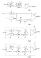
- Figure 1 shows an example of a loss detector of classic carrier.
- This detector includes a computer 1 of the level of the received signal comprising a circuit 2 for determining absolute value (providing the absolute value of the amplitude of the signal received Rx) whose output is sent to an averager 3 consisting of a recursive first order frequency low pass filter of zero cutoff.
- the Rx signal received by the computer 1 corresponds to the signal received by the modem after scanning.
- the averager 3 is used to smooth the corrugations at the output of the circuit 2 and to avoid inadvertent switching of the detector.
- a comparator 4 of the detector receives, on a positive input, the output of the averager 3 which constitutes the output of the computer 1.
- a negative input of comparator 4 receives a predetermined threshold value THRSH at which the received signal level should be compared.
- the output of comparator 4 delivers a detection signal DETECT with two states (ON or OFF) indicating the presence or the absence of a carrier.
- a disadvantage of this type of detector is that the characteristics of the transmission line between two modems can vary the signal level significantly received. These variations in the level of the received signal can be understood, for example, between 0 dBm and -48 dBm. By using, for example, for the THRSH threshold, a level of -24 dBm, any signal received below -24 dBm will be interpreted as carrier loss. Conversely, if noise is mixed with signal, the detector may not detect carrier loss.
- Document JP-A-06 014062 describes another example of carrier loss detector using a threshold memorized on the energy base of the received signal.
- a detector is particularly complex and requires additional resources to order memorizing the energy threshold.
- it does not allow not an adaptation of an existing modem equipped with a detector such as shown in Figure 1 without causing changes the modem receiver.
- Another disadvantage of such detector is that it is likely to generate errors of detection due to filter response time (bandpass) used.
- the present invention aims to overcome these drawbacks by proposing a carrier loss detector which is both fast and reliable.
- WO-A-92/21193 describes another detector of carrier loss using the average of the amplitude values of the received signal for determining an adaptive carrier loss detection threshold.
- the invention also aims to propose such a detector which can be adapted to a carrier loss detector and / or an existing modem without causing significant modifications to the modem receiver.
- said means include a threshold storage register which corresponds to a level of amplitude of the signal received during a sequence of determined signals and a switch for controlling memorizing the amplitude of the signal received from the first calculator at the appearance of the sequence of determined signals, said sequence being chosen to present signals of calibrated amplitude.
- the amplitude level to be memorized is assigned a coefficient, less than unity, using a first multiplier inserted between an output of the first computer and an input register memory.
- the value of the multiplier is chosen so that the stored threshold value is attenuated, relative to the output of the first computer, with a value corresponding at least to the maximum amplitude of ripples that can present the output of the first computer.
- the detector is associated with a device for identifying the sequence of determined signals which delivers a control signal said switch, said sequence having a frequency spectrum of two determined frequencies.
- said identification device comprises a bandpass filter, associated with a second amplitude calculator whose output is sent, via a second multiplier, to a first input of a second comparator, and a low-pass filter, associated with a third amplitude calculator including one output is sent, via a third multiplier, to a second input of the second comparator.
- said identification device comprises a notch filter, associated with a second amplitude calculator including an output is sent to a first input of a second comparator, a second input of the second comparator receiving the output of a third amplitude calculator whose input receives, directly, said received signal.
- a multiplier by a predetermined coefficient, is inserted between the output of each computer from the identification device and the input of the second comparator to which said computer is associated.
- the coefficient of the multiplier associated with the second calculator is greater than the coefficient of the multiplier associated with the third calculator.
- each amplitude calculator includes a determination circuit of the absolute value of the amplitude of the received signal and, constituting an average, a recursive low-pass digital filter of the first order at zero cutoff frequency.
- a carrier loss detector includes a comparator 4 of the level of the received signal Rx, which is supplied to it on a positive input by an amplitude calculator 1 consisting of a circuit determination of the absolute value of the amplitude of the received signal and an average. According to the invention, it is preferred to use a computer of amplitude which has the advantage of an implementation easier than an energy calculator squaring the signal level received. Comparator 4 receives, on its input negative, a THRSH threshold value from a register 5.
- the carrier according to the invention differs from the conventional detector represented in Figure 1 by the presence of a switch 6 responsible for periodically initiating registration, in the register 5, of the level present at the output of the amplitude calculator 1, assigned a coefficient K0 by means of a multiplier 7.
- the rest position of switch 6 is the position shown in Figure 2.
- a feature of the present invention is that the THRSH threshold and the current level of the received signal are both obtained by means of the same amplitude calculator 1.
- the operation of a detector according to the invention is not altered by possible drifts in the operation of the computer, insofar as such drifts are not likely to cause divergences between the calculation of the threshold and the current level.
- it makes the operation of the detector independent of manufacturing tolerances of the computer. Which is not the case detectors (for example, a detector as described in the document JP-A-06 014062) which use separate computers to get the current threshold and level.
- An advantage of the present invention is that the detector takes into account noise, which may be mixed with signal received, for determining the threshold and the current level amplitude.
- the THRSH threshold is adapted by taking, for a new value, the amplitude of the signal received Rx during a determined sequence which is chosen to correspond to an emission of a sequence of calibrated signals in amplitude.
- the choice of such a sequence is motivated by the fact that the level of the signal received Rx during this sequence, affected by the coefficient K0 less than unity, can then represent a THRSH threshold which corresponds to an absence of transmission of data.
- determined signals which are emitted during a learning phase present between each document page transmission, to make this adaptation of the THRSH threshold.
- the recommendations CCITT provide for a specific learning procedure for each transmission standard by fixing the type of signals to be transmitted and the maximum duration of the learning procedure.
- standard V27 for example, which corresponds to one of the standards used for faxing, a procedure is divided into five segments.
- a first segment consists of a pure carrier (devoid of modulation) transmitted at the carrier frequency of data transmission, for example, 1800 Hz for the V27 standard.
- a second segment consists of no emissions for a certain period.
- a third segment consists of a signal modulated by a given frequency, in phase and in phase opposition.
- This frequency is, for example, 1600 Hz for the V27 standard. In the frequency domain, this corresponds to emitting two frequencies pure, one at 1000 Hz, the other at 2600 Hz.
- a fourth segment consists of a scrambled signal random in a frequency range.
- this frequency range is between 1000 and 2600 Hz.
- a fifth segment consists of a scrambled signal encoded in a predetermined manner.
- the invention proposes to use the third segment to adapt the THRSH loss detection threshold carrier.
- the choice of this segment three is motivated by the fact that the first two segments are not always present. In indeed, they are only present in learning phases relating to modems with echo cancellation modules.
- the fourth and fifth segments they include a carrier modulation which approaches modulation by data symbols and are therefore difficult to distinguish signals received during the transmission of a page of document.
- segment three has the advantage of being already detected by the modem, in particular, to adjust a command automatic gain. So we already have in the modem a ENABLE signal indicating the presence of this segment, coming from a device 3 for identifying segment three, which can then serve as control signal of the adaptation switch 6 threshold.
- An advantage of the present invention is that by using, as a control signal, a signal already present in the modem, the detector of an existing modem, for example such as shown in figure 1, can be modified to obtain a detector according to the invention. Indeed, switch 6, the multiplier 7 and register 5 can be inserted between the output of computer 1 and the negative input of comparator 4, without another modification of the detector as shown in Figure 1.
- K0 a value as it represents, for the THRSH threshold value obtained in the presence of segment three, an attenuation of the level of the signal received Rx which makes it possible to consider that it corresponds to loss of transmission.
- the attenuation level obtained is greater than the maximum amplitude ripples presented by the output of the calculator averager 1 in order to avoid inadvertent switching.
- the coefficient K0 could be of the order of 0.25 representing an attenuation of the order of 12 dB.
- the coefficient K0 could be of the order 0.125 representing an attenuation of the order of 18 dB.
- FIG. 3 represents a conventional embodiment a device 3 for identifying segment three, the output of which ENABLE is used, according to the invention, to control the switch 6.
- This circuit includes a bandpass filter 9 and a low-pass filter 10 each receiving the signal Rx.
- the Rx signal that filters 9 and 10 receive matches, as in the case of figure 2, to the signal received by the modem after scanning in an analog / digital converter (not shown).
- Each filter 9 or 10 is followed by an amplitude calculator, 11 and 12 respectively.
- a comparator 13 receives, on a first input, the output of a multiplier 14 multiplying the output of the computer 11 by a coefficient K1 and, over a second input, the output of a multiplier 15 multiplying the output of the calculator 12 by a coefficient K2.
- the comparator output 13 provides a two-state ENABLE signal indicating the presence or the absence of segment three in the signal received Rx.
- the coefficient K1 of multiplier 14 is approximately double the coefficient Multiplier K2 15.
- the filter bandpass 9 is a narrow filter centered on the frequency of 1000 Hz and the low pass filter 10 has a frequency of 1760 Hz cutoff.
- the first comparator input 13 is at a level higher than its second Entrance. Indeed, double the output level of the bandpass filter 9 is higher than the output level of the low pass filter 10.
- the output level of the low pass filter 10 is greater than twice the output level of the bandpass filter 9 due to the narrowness of the latter.
- the transmission time of segment three on the transmission line depends on the standard. More precisely, the duration of this third segment depends on the option in which the modems are found among two options which correspond, respectively, to an initial learning (at the start of the communication) or to an intermediate learning (between each page).
- the intermediate learning option called option a
- option b has a duration of 50 symbol intervals.
- the durations are expressed in numbers of symbol intervals, or bauds, because they depend on the bit rate per bit of the transmission, the V27 ter standard providing for two transmission speeds (1200 baud or 2400 bps and 1600 baud or 4800 bits / s).
- a conventional segment three detector works properly for a long segment three (for example, option b of the V27 ter standard which corresponds to 50 baud, or 31.25 ms), it does not allow reliable detection of the segment three if this is only transmitted for a short time (for example, option a of the V27 ter standard which corresponds to 14 baud, or 8.75 ms). This is due to the response time of the bandpass filter 1 whose time constant is greater than 14 baud due to its narrowness.
- a digital bandpass filter is conventionally at least a second order recursive filter consisting of from integrators, multipliers and delay elements (shift registers).
- the structure and behavior of a filters of this type have been described by P.-M. BEAUFILS and M. RAMI in the book “Digital filtering", pages 216 to 224.
- a disadvantage of this type of filter is that obtaining a narrow bandpass filter, which is necessary to avoid not cause false segment three detections, leads to a slow filter.
- the device identification of segment three including the output signal ENABLE controls the switch 6, is constituted according to the representation in Figure 4.
- the recognition device comprises a notch filter 16 on which the signal received Rx by the modem is sent after scanning.
- the output of this notch filter 16 is sent to a first amplitude calculator 11 whose output is connected to a first input of a comparator 13.
- the received signal Rx is also sent directly to a second amplitude calculator 12 whose output is connected to a second comparator input 13.
- a multiplier respectively 14 and 15, is inserted between the output of each computer 11 and 12 and the comparator input with which it is associated.
- These multipliers 14 and 15 affect each computer output 11 or 12 a positive coefficient and less than unity, respectively K1 and K2, K1 being greater than K2.
- the notch filter 16 has two frequencies of cutoff which correspond to the two frequencies present in the segment three, for the V27 ter standard, 1000 Hz and 2600 Hz.
- notch filter 16 An advantage of using such a notch filter 16 is that it is easily achievable as a digital filter non-recursive with a low time constant. That this is not the case for a bandpass filter since a non-recursive filter has only zeros (frequencies for which the attenuation is infinite). We should therefore multiply the number of filter delay elements to surround the center frequency of a multitude of zeros (cut frequencies) insofar as one seeks to obtain an uncut frequency determined, which would lead to a very short propagation time high signal in the filter. However, for a notch filter, the frequencies determined are precisely frequencies cut, so zeros.
- segment three causes a high level of output computer 12 which receives the live Rx signal, and a very low level at the output of the computer 11 insofar as both frequencies were cut by filter 16.
- Noise likely to be mixed with the received signal Rx here has no effect insofar as its contribution is practically the same on the two computers 11 and 12 because the notch filters are relatively narrow.
- Amplitude calculators 11 and 12 are, like the computer 1 (figure 2), made up of a circuit for determining the absolute value of the signal amplitude first order recursive digital low pass filter at zero cutoff frequency constituting an average.
- An advantage of the determination circuit as shown in Figure 4 is that in the design of a receiver of a modem, computers 1 (figure 2) and 11 (figure 4) can to be confused. Indeed, they receive the same signal (the signal received after scanning) and deliver the same information (an average value of the absolute value of the signal amplitude received).
- the coefficients of the multipliers 14 and 15 are, from preferably, chosen so that the output level of the computer 12 is halved in relation to the computer output level 11. This makes it easy to differentiate the two possible cases at comparator 13, one of the two comparator inputs (the first in the absence of segment three, the second in the presence of segment three) then always having a level higher than the other.
Description
Claims (10)
- Détecteur de perte de porteuse dans un modem récepteur d'une transmission d'un document par télécopie, comportant :un premier calculateur d'amplitude (1) du signal reçu (Rx),un premier comparateur (4) de cette amplitude par rapport à un seuil (THRSH), etdes moyens (5, 6, 7, 8) pour réaliser une adaptation dudit seuil (THRSH) entre chaque page du document transmis.
- Détecteur de perte de porteuse selon la revendication 1, caractérisé en ce que lesdits moyens comportent un registre (5) de mémorisation d'un seuil (THRSH) qui correspond à un niveau d'amplitude du signal reçu (Rx) pendant une séquence de signaux déterminés et un commutateur (6) destiné à commander la mémorisation de l'amplitude du signal reçu (Rx) issue du premier calculateur (1) à l'apparition de la séquence de signaux déterminés, ladite séquence étant choisie pour présenter des signaux d'amplitude calibrée.
- Détecteur de perte de porteuse selon la revendication 2, caractérisé en ce que le niveau d'amplitude devant être mémorisé est affecté d'un coefficient (K0), inférieur à l'unité, au moyen d'un premier multiplieur (7) intercalé entre une sortie du premier calculateur (1) et une entrée de mémorisation du registre (5).
- Détecteur de perte de porteuse selon la revendication 3, caractérisé en ce que la valeur du coefficient multiplicateur (K0) est choisie pour que la valeur du seuil (THRSH) mémorisé soit atténuée, par rapport à la sortie du premier calculateur (1), d'une valeur correspondant au moins à l'amplitude maximale d'ondulations que peut présenter la sortie du premier calculateur (1).
- Détecteur de perte de porteuse selon l'une quelconque des revendications 2 à 4, caractérisé en ce qu'il est associé à un dispositif d'identification (8) de la séquence de signaux déterminés, qui délivre un signal de commande (ENABLE) audit commutateur (6), ladite séquence possédant un spectre fréquentiel de deux fréquences déterminées.
- Détecteur de perte de porteuse selon la revendication 5, caractérisé en ce que ledit dispositif d'identification (8) comporte un filtre passe-bande (9), associé à un second calculateur d'amplitude (11) dont une sortie est envoyée, par l'intermédiaire d'un second multiplieur (14), sur une première entrée d'un second comparateur (13), et un filtre passe-bas (10), associé à un troisième calculateur d'amplitude (12) dont une sortie est envoyée, par l'intermédiaire d'un troisième multiplieur (15), sur une seconde entrée du second comparateur (13).
- Détecteur de perte de porteuse selon la revendication 5, caractérisé en ce que ledit dispositif d'identification (8) comporte un filtre coupe-bandes (16), associé à un second calculateur d'amplitude (11) dont une sortie est envoyée sur une première entrée d'un second comparateur (13), une seconde entrée du second comparateur (13) recevant la sortie d'un troisième calculateur d'amplitude (12) dont l'entrée reçoit, directement, ledit signal reçu (Rx).
- Détecteur de perte de porteuse selon la revendication 7, caractérisé en ce qu'un multiplieur (14, 15), par un coefficient prédéterminé (K1, K2), est intercalé entre la sortie de chaque calculateur (11, 12) du dispositif d'identification (8) et l'entrée du second comparateur (13) à laquelle ledit calculateur (11, 12) est associé.
- Détecteur de perte de porteuse selon l'une des revendications 6 ou 8, caractérisé en ce que le coefficient (K1) du multiplieur (14) associé au second calculateur (11) est supérieur au coefficient (K2) du multiplieur (15) associé au troisième calculateur (12).
- Détecteur de perte de porteuse selon l'une quelconque des revendications 1 à 9, caractérisé en ce que chaque calculateur d'amplitude (1, 11, 12) comprend un circuit (2) de détermination de la valeur absolue de l'amplitude du signal reçu (Rx) et, constituant un moyenneur (3), un filtre numérique passe-bas récursif du premier ordre à fréquence de coupure nulle.
Applications Claiming Priority (2)
| Application Number | Priority Date | Filing Date | Title |
|---|---|---|---|
| FR9411212 | 1994-09-14 | ||
| FR9411212A FR2724517B1 (fr) | 1994-09-14 | 1994-09-14 | Detecteur de perte de porteuse dans un modem de telecopieur |
Publications (2)
| Publication Number | Publication Date |
|---|---|
| EP0702481A1 EP0702481A1 (fr) | 1996-03-20 |
| EP0702481B1 true EP0702481B1 (fr) | 1999-11-17 |
Family
ID=9467101
Family Applications (1)
| Application Number | Title | Priority Date | Filing Date |
|---|---|---|---|
| EP95410099A Expired - Lifetime EP0702481B1 (fr) | 1994-09-14 | 1995-09-08 | Détecteur de perte de porteuse dans un modem de télécopieur |
Country Status (4)
| Country | Link |
|---|---|
| US (1) | US5815534A (fr) |
| EP (1) | EP0702481B1 (fr) |
| DE (1) | DE69513355T2 (fr) |
| FR (1) | FR2724517B1 (fr) |
Families Citing this family (17)
| Publication number | Priority date | Publication date | Assignee | Title |
|---|---|---|---|---|
| US6553518B1 (en) | 1999-03-08 | 2003-04-22 | International Business Machines Corporation | Severe error detectors, methods and computer program products that use constellation specific error event thresholds to detect severe error events during demodulation of a signal comprising symbols from a plurality of symbol constellations |
| US6661847B1 (en) | 1999-05-20 | 2003-12-09 | International Business Machines Corporation | Systems methods and computer program products for generating and optimizing signal constellations |
| US6823004B1 (en) | 1999-10-29 | 2004-11-23 | International Business Machines Corporation | Methods, systems and computer program products for monitoring performance of a modem during a connection |
| US6611563B1 (en) | 1999-10-29 | 2003-08-26 | International Business Machines Corporation | Systems, methods and computer program products for data mode refinement of modem constellation points |
| US6823017B1 (en) | 1999-10-29 | 2004-11-23 | International Business Machines Corporation | Systems, methods and computer program products for filtering glitches from measured values in a sequence of code points |
| US6650657B1 (en) | 1999-10-29 | 2003-11-18 | International Business Machines Corporation | Systems, methods and computer program products for identifying digital impairments in modem signals |
| US6792004B1 (en) | 1999-10-29 | 2004-09-14 | International Business Machines Corporation | Systems, methods and computer program products for averaging learned levels in the presence of robbed-bit signaling based on proximity |
| US6816545B1 (en) | 1999-10-29 | 2004-11-09 | International Business Machines Corporation | Systems, methods and computer program products for identifying digital impairments in modems based on clusters and/or skips in pulse code modulation signal levels |
| US6662322B1 (en) | 1999-10-29 | 2003-12-09 | International Business Machines Corporation | Systems, methods, and computer program products for controlling the error rate in a communication device by adjusting the distance between signal constellation points |
| US6754258B1 (en) | 1999-10-29 | 2004-06-22 | International Business Machines Corporation | Systems, methods and computer program products for averaging learned levels in the presence of digital impairments based on patterns |
| US6765955B1 (en) | 1999-10-29 | 2004-07-20 | International Business Machines Corporation | Methods, systems and computer program products establishing a communication configuration for a modem connection to compensate for echo noise |
| US6826157B1 (en) | 1999-10-29 | 2004-11-30 | International Business Machines Corporation | Systems, methods, and computer program products for controlling data rate reductions in a communication device by using a plurality of filters to detect short-term bursts of errors and long-term sustainable errors |
| US6792040B1 (en) | 1999-10-29 | 2004-09-14 | International Business Machines Corporation | Modems having a dual power mode capability and methods of operating same |
| US6505222B1 (en) | 1999-10-29 | 2003-01-07 | International Business Machines Corporation | Systems methods and computer program products for controlling undesirable bias in an equalizer |
| US6452966B1 (en) * | 2000-01-19 | 2002-09-17 | Charles Industries, Ltd. | Digital signal carrier detector |
| US8131238B2 (en) * | 2008-03-20 | 2012-03-06 | Infineon Technologies Ag | Carrier signal detection |
| US10200163B1 (en) * | 2017-08-22 | 2019-02-05 | Texas Instruments Incorporated | Small and seamless carrier detector |
Family Cites Families (10)
| Publication number | Priority date | Publication date | Assignee | Title |
|---|---|---|---|---|
| US3990048A (en) * | 1973-11-23 | 1976-11-02 | Xerox Corporation | Carrier detect circuit |
| US4387401A (en) * | 1979-05-30 | 1983-06-07 | Rca Corporation | Carrier detector apparatus useful in a multiband sweep type tuning system |
| US4554508A (en) * | 1983-12-07 | 1985-11-19 | American Microsystems, Incorporated | Carrier detection circuit |
| JPS636935A (ja) * | 1986-06-26 | 1988-01-12 | Toshiba Corp | プリアンブル検出回路 |
| US5181226A (en) * | 1989-03-06 | 1993-01-19 | Raytheon Company | Threshold level generator |
| US5596418A (en) * | 1990-08-17 | 1997-01-21 | Samsung Electronics Co., Ltd. | Deemphasis and subsequent reemphasis of high-energy reversed-spectrum components of a folded video signal |
| US5260974A (en) * | 1991-05-10 | 1993-11-09 | Echelon Corporation | Adaptive carrier detection |
| JPH0614062A (ja) * | 1992-06-25 | 1994-01-21 | Mitsubishi Electric Corp | キャリア検出器 |
| JPH06244878A (ja) * | 1993-02-18 | 1994-09-02 | Fujitsu Ltd | 変復調装置 |
| US5598441A (en) * | 1994-10-13 | 1997-01-28 | Westinghouse Electric Corp. | Carrier acquisition technique for mobile radio QPSK demodulator |
-
1994
- 1994-09-14 FR FR9411212A patent/FR2724517B1/fr not_active Expired - Fee Related
-
1995
- 1995-09-08 DE DE69513355T patent/DE69513355T2/de not_active Expired - Fee Related
- 1995-09-08 EP EP95410099A patent/EP0702481B1/fr not_active Expired - Lifetime
- 1995-09-12 US US08/527,055 patent/US5815534A/en not_active Expired - Lifetime
Also Published As
| Publication number | Publication date |
|---|---|
| FR2724517B1 (fr) | 1996-12-13 |
| EP0702481A1 (fr) | 1996-03-20 |
| DE69513355D1 (de) | 1999-12-23 |
| FR2724517A1 (fr) | 1996-03-15 |
| DE69513355T2 (de) | 2000-06-08 |
| US5815534A (en) | 1998-09-29 |
Similar Documents
| Publication | Publication Date | Title |
|---|---|---|
| EP0702481B1 (fr) | Détecteur de perte de porteuse dans un modem de télécopieur | |
| EP0757452A1 (fr) | Système de télécommunication au travers de lignes d'alimentation d'énergie | |
| EP0580216A1 (fr) | Système et récepteur de signaux à répartition multiplexée de fréquences orthogonales muni d'un dispositif de synchronisation de fréquences | |
| EP0421897B1 (fr) | Extracteur de données numériques dans un signal vidéo | |
| WO2004023682A1 (fr) | Systeme et procede de transmission de donnees par ondes acoustiques | |
| EP0013343A1 (fr) | Procédé et dispositif pour détecter une séquence pseudo-aléatoire de changements de phase de 0 degré et 180 degrés de la porteuse dans un récepteur de données | |
| EP0732803A1 (fr) | Procédé et dispositif de démodulation par échantillonnage | |
| EP0125979B1 (fr) | Démodulateur de signaux, à enveloppe constante et phase continue, modulés angulairement par un train de symboles binaires | |
| EP0702469B1 (fr) | Détecteur de séquences d'apprentisssage modulées en sauts de fréquence | |
| FR2517906A1 (fr) | Annulateur d'echo a commande automatique de gain pour systemes de transmission | |
| EP0756389A1 (fr) | Circuit d'affectation d'un canal de transmission sur le réseau électrique | |
| FR2503496A1 (fr) | Circuit detecteur de bruit et recepteur de signal pour un recepteur a modulation de frequence | |
| EP0702468B1 (fr) | Dispositif d'identification d'une séquence de synchronisation | |
| EP0018242A1 (fr) | Procédé et dispositif de démodulation stochastique pour signaux modulés en sauts de phase, fonctionnant en temps partagé sur plusieurs canaux | |
| EP0063842A1 (fr) | Dispositif de récupération de porteuse pour une modulation d'amplitude et de phase à seize états et système de réception de données numériques comprenant un tel dispositif | |
| EP0080544A1 (fr) | Procédé de réception d'un signal de données en modulation à double bande latérale-porteuses en quadrature | |
| FR2717646A1 (fr) | Dispositif numérique de récupération large bande d'une porteuse. | |
| EP0755128A1 (fr) | Circuit de transmission de données binaires sur le réseau électrique utilisant plusieurs canaux de transmission | |
| FR2546693A1 (fr) | Annuleur d'echo a filtre numerique adaptatif pour systeme de transmission | |
| EP0061377A1 (fr) | Démodulateur numérique de signaux et récepteur ou système de télévision en couleurs comportant un tel démodulateur | |
| EP0035434B1 (fr) | Dispositif émetteur et dispositif récepteur pour la transmission de signaux numériques | |
| FR2846814A1 (fr) | Ameliorations se rapportant a la reduction des interferences pour la reception sans fil et ameliorations se rapportant au traitement d'un signal code par saut de frequence | |
| FR2720575A1 (fr) | Adaptateur post-démodulation. | |
| FR2846825A1 (fr) | Ameliorations se rapportant au traitement d'un signal code par saut de frequence | |
| FR2846815A1 (fr) | Ameliorations se rapportant a la reduction des interferences pour la reception sans fil et ameliorations se rapportant au traitement d'un signal code par saut de frequence |
Legal Events
| Date | Code | Title | Description |
|---|---|---|---|
| PUAI | Public reference made under article 153(3) epc to a published international application that has entered the european phase |
Free format text: ORIGINAL CODE: 0009012 |
|
| AK | Designated contracting states |
Kind code of ref document: A1 Designated state(s): DE FR GB IT |
|
| 17P | Request for examination filed |
Effective date: 19960828 |
|
| GRAG | Despatch of communication of intention to grant |
Free format text: ORIGINAL CODE: EPIDOS AGRA |
|
| 17Q | First examination report despatched |
Effective date: 19981118 |
|
| RAP3 | Party data changed (applicant data changed or rights of an application transferred) |
Owner name: STMICROELECTRONICS S.A. |
|
| GRAG | Despatch of communication of intention to grant |
Free format text: ORIGINAL CODE: EPIDOS AGRA |
|
| GRAH | Despatch of communication of intention to grant a patent |
Free format text: ORIGINAL CODE: EPIDOS IGRA |
|
| GRAH | Despatch of communication of intention to grant a patent |
Free format text: ORIGINAL CODE: EPIDOS IGRA |
|
| GRAA | (expected) grant |
Free format text: ORIGINAL CODE: 0009210 |
|
| AK | Designated contracting states |
Kind code of ref document: B1 Designated state(s): DE FR GB IT |
|
| REF | Corresponds to: |
Ref document number: 69513355 Country of ref document: DE Date of ref document: 19991223 |
|
| GBT | Gb: translation of ep patent filed (gb section 77(6)(a)/1977) |
Effective date: 19991220 |
|
| ITF | It: translation for a ep patent filed |
Owner name: BOTTI & FERRARI S.R.L. |
|
| PLBE | No opposition filed within time limit |
Free format text: ORIGINAL CODE: 0009261 |
|
| STAA | Information on the status of an ep patent application or granted ep patent |
Free format text: STATUS: NO OPPOSITION FILED WITHIN TIME LIMIT |
|
| 26N | No opposition filed | ||
| REG | Reference to a national code |
Ref country code: GB Ref legal event code: IF02 |
|
| PGFP | Annual fee paid to national office [announced via postgrant information from national office to epo] |
Ref country code: DE Payment date: 20040902 Year of fee payment: 10 |
|
| PGFP | Annual fee paid to national office [announced via postgrant information from national office to epo] |
Ref country code: FR Payment date: 20050823 Year of fee payment: 11 |
|
| PGFP | Annual fee paid to national office [announced via postgrant information from national office to epo] |
Ref country code: GB Payment date: 20050907 Year of fee payment: 11 |
|
| PG25 | Lapsed in a contracting state [announced via postgrant information from national office to epo] |
Ref country code: IT Free format text: LAPSE BECAUSE OF NON-PAYMENT OF DUE FEES Effective date: 20050908 |
|
| PG25 | Lapsed in a contracting state [announced via postgrant information from national office to epo] |
Ref country code: DE Free format text: LAPSE BECAUSE OF NON-PAYMENT OF DUE FEES Effective date: 20060401 |
|
| GBPC | Gb: european patent ceased through non-payment of renewal fee |
Effective date: 20060908 |
|
| REG | Reference to a national code |
Ref country code: FR Ref legal event code: ST Effective date: 20070531 |
|
| PG25 | Lapsed in a contracting state [announced via postgrant information from national office to epo] |
Ref country code: GB Free format text: LAPSE BECAUSE OF NON-PAYMENT OF DUE FEES Effective date: 20060908 |
|
| PG25 | Lapsed in a contracting state [announced via postgrant information from national office to epo] |
Ref country code: FR Free format text: LAPSE BECAUSE OF NON-PAYMENT OF DUE FEES Effective date: 20061002 |