EP0702828B1 - Mechanically incompatible magnetic recording tape cartridges having the same form factor - Google Patents
Mechanically incompatible magnetic recording tape cartridges having the same form factor Download PDFInfo
- Publication number
- EP0702828B1 EP0702828B1 EP94918155A EP94918155A EP0702828B1 EP 0702828 B1 EP0702828 B1 EP 0702828B1 EP 94918155 A EP94918155 A EP 94918155A EP 94918155 A EP94918155 A EP 94918155A EP 0702828 B1 EP0702828 B1 EP 0702828B1
- Authority
- EP
- European Patent Office
- Prior art keywords
- tape
- cartridge
- drive
- tape cartridge
- improved
- Prior art date
- Legal status (The legal status is an assumption and is not a legal conclusion. Google has not performed a legal analysis and makes no representation as to the accuracy of the status listed.)
- Expired - Lifetime
Links
- 230000007246 mechanism Effects 0.000 claims description 10
- 230000013011 mating Effects 0.000 claims description 6
- 238000003780 insertion Methods 0.000 description 6
- 230000037431 insertion Effects 0.000 description 6
- 230000006378 damage Effects 0.000 description 2
- 210000003811 finger Anatomy 0.000 description 2
- 230000003993 interaction Effects 0.000 description 2
- 238000004519 manufacturing process Methods 0.000 description 2
- 239000000463 material Substances 0.000 description 2
- 238000011084 recovery Methods 0.000 description 2
- 210000003813 thumb Anatomy 0.000 description 2
- 230000000903 blocking effect Effects 0.000 description 1
- 238000013500 data storage Methods 0.000 description 1
- 230000003247 decreasing effect Effects 0.000 description 1
- 230000007613 environmental effect Effects 0.000 description 1
- 230000003203 everyday effect Effects 0.000 description 1
- 239000002184 metal Substances 0.000 description 1
- 238000000034 method Methods 0.000 description 1
- 230000003287 optical effect Effects 0.000 description 1
- 230000002093 peripheral effect Effects 0.000 description 1
- 238000009877 rendering Methods 0.000 description 1
- 230000006641 stabilisation Effects 0.000 description 1
- 238000011105 stabilization Methods 0.000 description 1
Images


Classifications
-
- G—PHYSICS
- G11—INFORMATION STORAGE
- G11B—INFORMATION STORAGE BASED ON RELATIVE MOVEMENT BETWEEN RECORD CARRIER AND TRANSDUCER
- G11B23/00—Record carriers not specific to the method of recording or reproducing; Accessories, e.g. containers, specially adapted for co-operation with the recording or reproducing apparatus ; Intermediate mediums; Apparatus or processes specially adapted for their manufacture
- G11B23/02—Containers; Storing means both adapted to cooperate with the recording or reproducing means
- G11B23/04—Magazines; Cassettes for webs or filaments
- G11B23/08—Magazines; Cassettes for webs or filaments for housing webs or filaments having two distinct ends
- G11B23/087—Magazines; Cassettes for webs or filaments for housing webs or filaments having two distinct ends using two different reels or cores
- G11B23/08707—Details
- G11B23/08714—Auxiliary features
-
- G—PHYSICS
- G11—INFORMATION STORAGE
- G11B—INFORMATION STORAGE BASED ON RELATIVE MOVEMENT BETWEEN RECORD CARRIER AND TRANSDUCER
- G11B23/00—Record carriers not specific to the method of recording or reproducing; Accessories, e.g. containers, specially adapted for co-operation with the recording or reproducing apparatus ; Intermediate mediums; Apparatus or processes specially adapted for their manufacture
- G11B23/02—Containers; Storing means both adapted to cooperate with the recording or reproducing means
- G11B23/04—Magazines; Cassettes for webs or filaments
- G11B23/08—Magazines; Cassettes for webs or filaments for housing webs or filaments having two distinct ends
- G11B23/087—Magazines; Cassettes for webs or filaments for housing webs or filaments having two distinct ends using two different reels or cores
- G11B23/08707—Details
- G11B23/08778—Driving features, e.g. belt
Definitions
- This invention involves belt-driven magnetic recording tape cartridges, and particularly features incorporated into the cartridges to mechanically distinguish between belt-driven cartridges containing magnetic tapes with different recording characteristics, but having the same form factor.
- a popular type of magnetic data recording tape is contained within a belt-driven cartridge, commonly called a “tape cartridge” or “data cartridge.”
- the cartridge encloses the tape, which is wound on two reels or hubs driven by a friction-coupled endless internal belt and capstan system in which the belt contacts the periphery of the wound tape and the capstan engages an external drive mechanism in a magnetic tape drive.
- the term “tape cartridge” will refer to a belt-driven magnetic recording tape cartridge of this type.
- these tape cartridges are operated by driving the tape past a read/write head assembly of a tape drive in a linear or longitudinal fashion at speeds between about 0.64-3.66 m/s (25-150 in/s).
- the magnetic data on the tape is recorded or read in a linear serpentine path.
- the tape cartridges of the present invention are constructed so as to minimize the longitudinal tension on the tape that might otherwise alter the dimensional characteristics of the tape.
- the tape cartridges of tne present invention use the friction-coupled endless internal belt and capstan system to drive the tape past the read/write head assembly without directly tensioning the tape itself.
- EP-A-0 389 121 describes a data protection feature for a tape cartridge that enables sensing circuitry within the tape drive to distinguish between two different types of tape cartridges having otherwise identical form factors.
- EP-A-0 205 074 disclosed a further embodiment of a disc cartridge having a countersunk lip located at the front end of opposite side walls. This countersunk lip cooperates with a blocking element of the drive for preventing wrong insertion (upside down) of the disc cartridge into the drive.
- the invention relates to a housing for a first belt-driven tape cartridge that has a substantially similar form factor but is mutually incompatible with a second belt-driven tape cartridge of the same form factor.
- the housing comprises a top plate having a top surface and periphery outline substantially the same as the periphery outline of the physical form factor; a front wall perpendicularly attached to the top plate along a front edge margin of the top plate and having a front surface including: structure defining a belt-driven tape transport aperture, and structure defining a separate read/write access aperture; a back wall perpendicularly attached to the top plate along a back edge margin of the top plate; and a pair of side walls perpendicularly attached to the top plate along respective side edge margins of the top plate, each side wall having a side surface.
- At least one of the side walls includes a countersunk lip having transverse edges defined along a portion of the side edge margin of the top plate and indented from the top surface and the side surface, and at least one of the side walls includes an indented rail-mating channel defining a rib along the top of the portion of the side wall and extending backward along a portion of the side wall from the margin of the front surface that is less than a distance of a similar indented rail-mating channel in the second tape cartridge.
- the housing for the first tape cartridge has substantially the same form factor as the second tape cartridge, but the first tape cartridge can not be inserted into a tape drive for reading the second tape cartridge due to the distance of the indented rail-mating channel of the one of the side walls being less than the distance of the similar indented rail-mating channel in the second tape cartridge. Conversely, the second tape cartridge cannot be inserted into a tape drive for reading the first tape cartridge due to a lack of the countersunk lip on the one of the side walls.
- the invention is a housing for a first belt-driven tape cartridge that has a substantially similar form factor but is backward incompatible with a second belt-driven tape cartridge of the same form factor.
- the second tape cartridge includes a pair of identical indented rail-mating channels along a respective one of each of a pair of side walls for mating with a pair of identical mounting rails in a tape drive for reading the second tape cartridge.
- the housing for the first tape cartridge comprises: a top plate having a top surface and periphery outline substantially the same as the periphery outline of the physical form factor; a front wall perpendicularly attached to the top plate along a front edge margin of the top plate; a back wall perpendicularly attached to the top plate along a back edge margin of the top plate; and a first side wall and a second side wall perpendicularly attached to the top plate along respective side edge margins of the top plate.
- a front surface on the front wall includes: structure defining a belt-driven tape transport aperture, structure defining a separate read/write access aperture, and a door covering the read/write access aperture and pivoting about an axis that is adjacent a corner of the front wall along the first side wall and perpendicular to the top plate, the door including a portion that extends beyond the axis to the side margin of the first side wall.
- a first indented rail-mating channel extends backward along a portion of the first side wall from the front edge margin a distance that is substantially the same as a distance of the identical indented rail-mating channels in the second tape cartridge such that a mounting rail in a tape drive for reading the first tape cartridge will engage the portion of the door that extends beyond the axis as the mounting rail slides along the indented channel to open the door and provide access to the read/write access aperture.
- a second indented rail-mating channel extends backward along a portion of the second side wall from the front edge margin a distance that is substantially less than the distance of the identical indented rail-mating channels of the second tape cartridge such that the first tape cartridge can not be inserted into the tape drive for reading the second tape cartridge.
- Figure 1 is a sectional top view of an existing tape cartridge shown positioned in an existing linear serpentine path belt-driven tape drive.
- Figure 2 is an edge view showing the front wall of the tape cartridge of Figure 1.
- Figure 3 is a top perspective view of the tape cartridge of Figure 1 shown positioned for insertion in the existing belt-driven tape drive.
- Figure 4 is a bottom perspective view of the tape cartridge of Figure 3.
- Figure 5 is a sectional top view of an embodiment of a tape cartridge in accordance with the present invention shown positioned in an arcuate scanning belt-driven tape drive.
- Figure 6 is an edge view showing the front wall of the tape cartridge of Figure 5.
- Figure 7 is a top perspective of the tape cartridge of Figure 5 shown positioned for insertion in an arcuate scanning belt-driven tape drive.
- Figure 8 is a bottom perspective view of the tape cartridge of Figure 7.
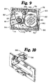
- Figure 9 is a top view, in partial section, of the tape cartridge of Figure 5 showing the rotation of the tape and endless belt.
- Figure 10 is a partial cutaway perspective of a portion of a belt-driven tape drive showing a rail member adapted to interface with the tape cartridge of Figure 5.
- FIGs 1-4 show an existing belt-driven mini-cartridge 10.
- mini-cartridge 10 is shown positioned in a tape transport portion 12 of a belt-driven tape drive (a machine for reading, writing, and erasing magnetic data to and from the tape as appropriate, the electronics and other portions of which are not shown).
- the belt-driven tape drive may record magnetic data on the tape in any format, depending upon the configuration of a read/write assembly 11 of the tape drive.
- tape cartridge 10 includes a base plate 15 and a cover 17, together defining a relatively thin, generally rectangular enclosure having a front wall 18.
- Figure 1 shows that within cover 17 are reel hubs 19 and 20, tape guides 21, 22 and 23, supports 25, screw holes 26, tape 27, belt driving capstan 29, belt guide rollers 30 and 31 and drive belt 33.
- Reel hubs 19 and 20 are supported by cover 17 for free rotation about spaced parallel axes.
- Tape 27 is wound on reel hubs 19 and 20 in opposite directions about their axes.
- a tape guide path between the reel hubs is defined by the three guide pins 21, 22 and 23.
- One tape guide pin 21 is at one side of a cartridge cutaway portion 36, and the other two tape guide pins 22 and 23 are along and behind front wall 18 on the opposite side of cutaway portion 36.
- Drive belt 33 is thin, continuous, flexible, elastic and uniform in cross section. Drive belt 33 extends in a belt guide path that takes it around belt driving capstan 29 and belt guide rollers 30 and 31, contacting tape 27 on reel hubs 19 and 20. The elasticity, length, pretension and angle of wrap of belt 33 at the reel hubs provide the necessary contact to assure frictional driving of tape 27 and reel hubs 19 and 20 by drive belt 33.
- An opening 35 in front wall 18 of cover 17 provides access for a drive roller 14, part of tape transport portion 12 of the tape drive, to contact belt driving capstan 29. Rotation of belt driving capstan 29 by drive roller 14 of tape transport portion 12 causes belt 33 and tape 27 to move. Similarly, through cutaway portion 36 in front wall 18, read/write assembly 11 of tape transport portion 12 contacts magnetic tape 27. Cutaway portion 36 is normally covered by a door 37, which is pivoted on stud 38 adjacent a corner of cartridge 10, and biased by torsion spring 39 towards its closed position, flush with front wall 18.
- opposed side walls 40 and 41 of cartridge 10 each include a similar rail-mating channel or recess 42 as shown in Figure 4 that is defined along substantially the entire length of each of the side walls to expose a corresponding outermost portion of each side of base plate 15, including positioning notch 43.
- a series of ridges and grooves provides a gripping portion 44 to allow a user to easily handle and insert cartridge 10 by gripping cartridge 10 between a thumb and a finger, for example, positioned at gripping portions 44.
- a physical read/write indicator 45 is positioned on front wall 18 to interact with a sensing mechanism/circuit 46 in tape transport portion 12 to determine the write protection status of the tape cartridge 10.
- An optical tape sensor 32 is positioned just behind front wall 18 to interact with a tape sensing mechanism/circuit 34 to determine the end-of-tape status of tape cartridge 10.
- a pair of substantially identical elongate mounting rails 16 within tape transport portion 12 are positioned to mate over the exposed outermost portions of base plate 15 and along recesses 42 of side walls 40 and 41 to guide cartridge 10 into position as it is inserted, front wall 18 forward, into tape transport portion 10.
- Door 37 extends beyond its pivot stud 38 into a recessed portion of adjacent side wall 40, and the leading edge of the corresponding elongate rail 16 pivots door 37 to an open position as cartridge 10 is inserted into tape transport portion 10.
- a pair of tabs (not shown) in tape transport portion 12 engage notches 43 on base plate 15 as read/write assembly 11 and drive roller 14 are moved into operable position with tape cartridge 10 in order to firmly secure tape cartridge 10 in position within tape transport portion 12.
- Base plate 15 is preferably made of metal or any other dimensionally stable material so as to decrease the chance of any dimensional changes in the form factor of the tape cartridge due to, for example, environmental conditions or everyday wear and tear.
- recesses 42 guide tape cartridge 10 into initial position within tape transport portion 12 and that position is then locked by the interaction of the notches 43 on base plate 15 and the tabs in tape transport portion 12.
- tape cartridge 50 in accordance with the present invention will be described. While tape cartridge 50 of this embodiment has essentially the same form factor as existing tape cartridge 10, tape cartridge 50 is mechanically incompatible with tape transport portion 12 of existing belt-driven tape drives.
- a new tape drive which reads and writes tape cartridge 50 may also be configured so that existing tape cartridge 10 is mechanically incompatible with such a new tape drive. This mechanical mutual incompatibility is desirable, for example, when the recording and dimensional characteristics of the new tape cartridge are such that insertion of a new tape cartridge into an old tape drive would result in the destruction of magnetic data on the new tape cartridge and vice-versa.
- the present invention is applicable to any type of tape drives that have incompatible tape cartridges with the same form factor where a mechanical incompatibility of tape cartridges is required.
- tape cartridge 50 is magnetically pre-formatted for certain purposes and the incorrect insertion of one of these tape cartridges 50 into an old tape drive would result in the destruction of the pre-formatting, thereby rendering the tape cartridge essentially useless.
- tape cartridges of this type are used for backup and recovery purposes, there is a critical need for a fail-safe mechanical incompatibility as provided for by the present invention when magnetic tapes having different recording and dimensional characteristics are contained in tape cartridges that have the same form factor.
- tape cartridge 50 is adapted for use with an arcuate scanning tape drive of the type shown and described in WO 93/26005 which is incorporated in this application by reference.
- a tape transport portion 52 of the arcuate scanning tape drive in that reference is functionally similar to tape transport portion 12, except that a read/write assembly 51 is comprised of one or more read/write heads located on a rotatable head carriage that rotates at speeds on the order of 10,000 rpm and uses an arcuate scan path for recording magnetic data on a magnetic tape.
- the tape in an arcuate scanning tape drive moves past the head assembly at speeds less than 1 in/s (2.54 cm/s), and the scan path is essentially perpendicular to the longitudinal length of the tape.
- the magnetic tape In order to achieve high density magnetic recording with this type of tape drive, the magnetic tape must have an elasticity modulus that is very stable in both the longitudinal and transverse dimensions.
- tape cartridge 50 as shown in Figure 6 includes a base plate 55 and a cover 57, together defining a relatively thin, generally rectangular enclosure having a front wall 58.
- cover 57 within cover 57 are reel hubs 59 and 60, tape guides 61, 62 and 63, supports 65, screw holes 66, tape 67, belt driving capstan 69, belt guide rollers 70 and 71 and drive belt 73.
- An opening 75 in front wall 58 of cover 57 provides access for a drive roller 54, part of tape transport portion 52 of the tape drive.
- a cutaway portion 76 in front wall 58 allows read/write assembly 51 of tape transport portion 52 to contact magnetic tape 67.
- cutaway portion 76 is normally covered by a door 77, which is pivoted on stud 78 and biased by torsion spring 79 towards its closed position, flush with front wall 58.
- tape drive operation of tape cartridge 50 is similar to that of tape cartridge 10; however, in normal read/write operation, the tape 67 is advanced at a speed of less than about 1 in/s (2.54 cm/s). While the lower tape speed of the arcuate scanning tape drive might allow for a simpler tape drive operation, the preferred embodiment of the arcuate scanning tape drive includes a fast scan feature where a selected portion of tape 67 is read as the tape is advanced past the read/write assembly 51 at much faster speeds. This feature, combined with the manufacturing advantages of having similar internal components, is why tape cartridge 50 preferably uses tape drive operation components that are identical to those of tape cartridge 10.
- tape cartridge 50 of the preferred embodiment has three unique mechanical differences from tape cartridge 10.
- cutaway portion 76 is increased in size to accommodate the larger size of read/write assembly 51 of the preferred arcuate scanning tape drive.
- the size and centerline of opening 75 are slightly modified to accommodate the mechanics of drive roller 54.
- the centerline of opening is offset slightly to the right of the centerline of drive roller 54 due to interference problems in the operation of drive roller 54 of the preferred arcuate scanning tape drive.
- at least one of side walls 80 and 81 is provided with a mutually incompatible mechanical cartridge lockout mechanism.
- the cutaway portion 36 of the standard tape cartridge 10 does not provide sufficient room for the read/write assembly 51 to fully penetrate the tape 27.
- the drum diameter of an arcuate scanning read/write assembly 51 would need to be reduced from its preferred size, thereby decreasing the total data capacity that could be recorded.
- a mechanism within the arcuate scanning tape drive would have to pull the tape 27 from the cartridge 10 in order to allow the larger arcuate scanning read/write assembly 51 to fully access the tape 27. This option has the disadvantage of complicating tape handling and unnecessarily increasing the costs of the arcuate scanning tape drive.
- the present invention solves this problem by providing a door cutaway portion 76 that is enlarged from the standard mini-cartridge cutaway portion 36 to allow an arcuate scanning read/write assembly 51 to enter the cartridge 50 and access the full width of the magnetic tape 67.
- opening 75 of the preferred embodiment of cartridge 50 shown in Figure 6 is enlarged in length as compared to opening 35 of the standard mini-cartridge 10, although the preferred embodiment is not as tall as the standard mini-cartridge 10.
- the larger read/write assembly 51 of the arcuate scanning tape drive as shown in Figure 5, interferes with the normal positioning of the drive roller 54.
- the drive roller 54 of the arcuate scanning tape drive is offset to resolve this interference problem and, as a result, the opening 75 is enlarged to accommodate the shifted position of the drive roller 54.
- the mutually incompatible mechanical cartridge lockout mechanism of the preferred embodiment is implemented along one or both of a pair of side walls 80 and 81 of the cover 57.
- the opposed side walls 80 and 81 of cartridge 50 each include a recess or indented channel 82 defined along a portion of each of the side walls sufficient to expose a corresponding outermost portion of each side of base plate 55, including positioning notch 23.
- a series of series of ridges and grooves provide a gripping portion 84 to allow a user to easily handle and insert cartridge 50 by gripping cartridge 50 between a thumb and a finger, for example, positioned at gripping portions 84.
- a physical read/write indicator 85 is positioned on front wall 58 to interact with a sensing mechanism/circuit 72 in tape transport portion 50 to determine the write protection status of the tape cartridge 50.
- the mutually incompatible mechanical cartridge lockout mechanism comprises a pair of physical features preferably incorporated into side walls 80 and 81 of tape cartridge 50.
- each side wall 80, 81 has an indented channel portion 82 open to and extending a predefined length, less than the length of the side walls 81, backward from the front wall 58.
- Channel portion 82 mates with a corresponding cartridge guide 56 in the arcuate scanning tape drive to stabilize tape cartridge 50 within the arcuate scanning tape drive.
- one or both of the indented channel portions 82 have an abutting face 86 perpendicular to and integral with that side wall 80 or 81 and located at a distance from front wall 58 shorter than the predefined length of indented channel portion 82 of cartridge 10, to prevent corresponding cartridge rail 16 in the standard tape drive from mating with indented channel portion 82.
- Side wall 80 or 81 of cover 57 is provided with additional material or structure for abutting face 86 such that abutting face 86 is essentially rearward of notch 83 and forward of gripping portion 84 at a distance shorter than the full insertion mating distance of cartridge guide 16. Abutting face 86 prevents tape cartridge 50 from being fully inserted into the standard tape drive. As shown in Figure 10, a corresponding cartridge rail 56 of the arcuate scanning tape drive is shorter than cartridge rail 16, mating with indented channel 82 to allow tape cartridge 50 to be fully inserted in the arcuate scanning tape drive. The location of abutting face 86 allows cartridge rail 56 to perform its required stabilization functions, yet still provides for the incompatibility of tape cartridges 10 and 50 without altering the form factor of tape cartridge 50.
- one or both of side walls 80 and 81 have a countersunk lip 87 defined along a portion of a top edge of side walls 80 and 81. Lip 87 mates with a corresponding lockout flange 88 in the arcuate scanning tape drive as shown in Figure 10.
- the absence of a similar countersunk lip 87 on tape cartridge 10 prevents standard tape cartridge 10 from being fully inserted into the improved tape drive, due to the lockout flange 88 interacting with the non-countersunk top edge of side walls 40 and 41.
Description
Claims (1)
- An improved belt-driven tape cartridge (50) having a form factor and being mutually incompatible with a standard belt-driven tape cartridge (10) of the same form factor, the standard tape cartridge (10) and the improved tape cartridge (50) including:wherein the improved tape cartridge (50) is for use with a tape drive (52) having two guide rails (56), one guide rail being longer then the other, and a lockout flange (88) which prevents a standard tape cartridge (10) from being fully inserted into the improved tape drive (52) and not for use with a tape drive (12) having two guide rails (16) longer than the short guide rail (56) of the improved drive, the improved tape cartridge (50) being characterized in that:a base plate (15, 55) having dimensions and a periphery outline in accordance with the form factor of the tape drives (12, 52) that receive the tape cartridges (10, 50);a belt-driven tape transport system (19-33, 59-73) mounted on the base plate (15, 55) for presenting a magnetic recording tape (27, 67) along a front edge of the periphery outline; anda cover (17, 57) attached to the base plate (15, 55) having a front wall (18, 58), a pair of side walls (40, 41, 80, 81) each having a length, a back wall and a top, the front wall (18, 58) including:and each side wall (40, 41, 80, 81) having an indented rail-mating channel portion (42, 82) open to and extending a length less than the length of the side walls (40, 41, 80, 81) backward from the front wall (18, 58) for mating with a corresponding cartridge rail guide (16, 56) in the tape drive (12, 52) to stabilize the tape cartridge (10, 50) within the tape drive (12, 52),structure defining a drive aperture (35, 75) for permitting a drive mechanism (14, 54) in the tape drive (12, 52) to access the tape transport system (29, 69) to control the motion of the magnetic recording tape (27, 67), andstructure defining a read/write aperture (36, 76) for permitting a magnetic read/write assembly (11, 51) in the tape drive (12, 52) to access the magnetic tape (27, 67) for read/write operations;an abutting face (86) is provided perpendicular to and integral with at least one of the side walls (80, 81) and located at a distance from the front wall (58) shorter than the length of the corresponding indented rail-mating channel portion (40, 41) of the standard tape cartridge (12) to prevent the corresponding guide rail (16) in a tape drive (12) for the standard tape cartridge (10) from mating with the indented rail-mating channel portion (80, 81) of the improved tape cartridge (50); anda countersunk lip (87) defined along a portion of at least one edge of one of the side walls (80, 81) that mates with the corresponding lockout flange (88) in an improved tape drive (52) to allow the improved tape cartridge (50) to be inserted into the improved tape drive (52),whereby the improved tape cartridge (50) has substantially the same form factor as the standard tape cartridge (10) but is mechanically mutually incompatible with the standard tape cartridge (10).
Applications Claiming Priority (3)
| Application Number | Priority Date | Filing Date | Title |
|---|---|---|---|
| US7359293A | 1993-06-08 | 1993-06-08 | |
| US73592 | 1993-06-08 | ||
| PCT/US1994/006021 WO1994029863A1 (en) | 1993-06-08 | 1994-05-27 | Mechanically incompatible magnetic recording tape cartridges having the same form factor |
Publications (2)
| Publication Number | Publication Date |
|---|---|
| EP0702828A1 EP0702828A1 (en) | 1996-03-27 |
| EP0702828B1 true EP0702828B1 (en) | 1998-04-08 |
Family
ID=22114620
Family Applications (1)
| Application Number | Title | Priority Date | Filing Date |
|---|---|---|---|
| EP94918155A Expired - Lifetime EP0702828B1 (en) | 1993-06-08 | 1994-05-27 | Mechanically incompatible magnetic recording tape cartridges having the same form factor |
Country Status (7)
| Country | Link |
|---|---|
| US (1) | US5480103A (en) |
| EP (1) | EP0702828B1 (en) |
| JP (1) | JPH08511123A (en) |
| KR (1) | KR960702663A (en) |
| CN (1) | CN1125011A (en) |
| DE (1) | DE69409517T2 (en) |
| WO (1) | WO1994029863A1 (en) |
Families Citing this family (12)
| Publication number | Priority date | Publication date | Assignee | Title |
|---|---|---|---|---|
| KR970700910A (en) * | 1994-11-30 | 1997-02-12 | 이데이 노부유키 | Tape cartridge |
| EP0739011B1 (en) * | 1995-04-18 | 1999-11-03 | Iomega Corporation | Keying slots on cartridge |
| JP3857348B2 (en) * | 1996-02-20 | 2006-12-13 | ソニー株式会社 | Tape cartridge |
| JPH1011853A (en) | 1996-06-26 | 1998-01-16 | Sony Corp | Recording and reproducing device |
| EP0907179A1 (en) * | 1997-10-02 | 1999-04-07 | Verbatim Corporation | Belt driven recording tape cartridge |
| WO2000010162A2 (en) | 1998-08-14 | 2000-02-24 | Verbatim Corporation | Large capacity, high performance tape cartridge |
| US6045079A (en) * | 1998-08-14 | 2000-04-04 | Verbatim Corporation | Tape cartridge having a large door and pivotally mounted write protect arm |
| US6390402B2 (en) | 1998-08-14 | 2002-05-21 | Verbatim Corporation | Tape cartridge having lockout features |
| AU5655899A (en) * | 1998-09-10 | 2000-04-03 | Onstream, Inc. | Apparatus for writing and/or reading information |
| US6270030B1 (en) | 1999-09-28 | 2001-08-07 | Imation Corp. | System for controlling compatibility of tape cartridges having the same form factor |
| US6386471B1 (en) | 2000-11-20 | 2002-05-14 | Imation Corp. | System and method for automating the assembly of data storage devices |
| US7427043B2 (en) | 2002-08-22 | 2008-09-23 | Quantrum Corporation | Tape cartridge with multiple keying features |
Family Cites Families (21)
| Publication number | Priority date | Publication date | Assignee | Title |
|---|---|---|---|---|
| JPS5246086Y2 (en) * | 1972-05-09 | 1977-10-20 | ||
| JPS5444576Y2 (en) * | 1974-03-11 | 1979-12-21 | ||
| DE2547136B2 (en) * | 1974-10-21 | 1978-05-24 | Olympus Optical Co., Ltd., Tokio | Magnetic tape cassette |
| US4320422A (en) * | 1980-05-27 | 1982-03-16 | International Business Machines Corporation | File protect sleeve |
| JPS6343643Y2 (en) * | 1980-12-16 | 1988-11-14 | ||
| NL8201452A (en) * | 1982-04-06 | 1983-11-01 | Philips Nv | MAGNETIC TAPE CASSETTE. |
| CA1214268A (en) * | 1982-11-11 | 1986-11-18 | Akihisa Osawa | Video cassette designed for video theater use |
| US4549240A (en) * | 1982-11-26 | 1985-10-22 | Verbatim Corporation | Write protection device |
| JPS60163572U (en) * | 1984-04-03 | 1985-10-30 | ソニー株式会社 | tape cassette |
| JPS6133290U (en) * | 1984-07-28 | 1986-02-28 | ソニー株式会社 | Recording media storage cassette |
| DE3679105D1 (en) * | 1985-06-14 | 1991-06-13 | Yamaha Corp | SYSTEM FOR LOADING A DISK CARTRIDGE INTO A DISK PLAYER. |
| GB2208330B (en) * | 1987-07-27 | 1991-12-04 | Hitachi Ltd | An optical disc cartridge and a mechanism for preventing an incorrect insertion of a cartridge. |
| US4898338A (en) * | 1987-09-21 | 1990-02-06 | Fuji Photo Film Co., Ltd. | Magnetic tape cassette |
| CA2008873A1 (en) * | 1989-03-13 | 1990-09-13 | Sten R. Gerfast | Indication device for a magnetic recording tape cartridge |
| NL8900805A (en) * | 1989-04-03 | 1990-11-01 | Philips Nv | DEVICE WITH AN INPUT OPENING A STANDARD SIZE. |
| JPH0636522Y2 (en) * | 1989-11-22 | 1994-09-21 | ティアツク株式会社 | Disk cartridge erroneous insertion prevention mechanism |
| US5161079A (en) * | 1990-01-19 | 1992-11-03 | Matsushita Electric Industrial Co., Ltd. | Tape cassette with slidable shutter |
| US5240200A (en) * | 1990-03-30 | 1993-08-31 | Matsushita Electric Industrial Co., Ltd. | Tape cassette |
| JP2979592B2 (en) * | 1990-06-21 | 1999-11-15 | ソニー株式会社 | Disk cartridge |
| JPH04109478A (en) * | 1990-08-30 | 1992-04-10 | Sony Corp | Tape cassette |
| US5502704A (en) * | 1991-03-29 | 1996-03-26 | Sony Corporation | Disc recording and/or reproducing apparatus |
-
1994
- 1994-05-27 DE DE69409517T patent/DE69409517T2/en not_active Expired - Fee Related
- 1994-05-27 WO PCT/US1994/006021 patent/WO1994029863A1/en active IP Right Grant
- 1994-05-27 CN CN94192340A patent/CN1125011A/en active Pending
- 1994-05-27 JP JP7501872A patent/JPH08511123A/en active Pending
- 1994-05-27 EP EP94918155A patent/EP0702828B1/en not_active Expired - Lifetime
- 1994-05-27 KR KR1019950705296A patent/KR960702663A/en not_active Application Discontinuation
- 1994-10-24 US US08/328,749 patent/US5480103A/en not_active Expired - Fee Related
Also Published As
| Publication number | Publication date |
|---|---|
| EP0702828A1 (en) | 1996-03-27 |
| DE69409517T2 (en) | 1998-11-12 |
| KR960702663A (en) | 1996-04-27 |
| CN1125011A (en) | 1996-06-19 |
| DE69409517D1 (en) | 1998-05-14 |
| US5480103A (en) | 1996-01-02 |
| JPH08511123A (en) | 1996-11-19 |
| WO1994029863A1 (en) | 1994-12-22 |
Similar Documents
| Publication | Publication Date | Title |
|---|---|---|
| EP0702828B1 (en) | Mechanically incompatible magnetic recording tape cartridges having the same form factor | |
| US5547142A (en) | Tape cassette with internal tape cleaning and locking | |
| EP0406943A1 (en) | System for recording/reproducing signals on/from magnetic tape, and apparatus and cassette for use in the system | |
| US4498112A (en) | Tape cartridge receptacle | |
| JP3710410B2 (en) | Recording tape cartridge | |
| EP0295920B1 (en) | Magnetic tape cassettes | |
| EP0295921B1 (en) | Magnetic tape cassettes | |
| JPH11339439A (en) | Recording medium housing cassette | |
| KR100338448B1 (en) | Various dimensions of cassette and signal recording and reproducing system to keep recording medium inside | |
| US5504644A (en) | Recording/erasing prevention device | |
| US5786967A (en) | Tape cartridge including an indication device to distinguish between cartridges having different characteristics but nearly identical physical characteristics | |
| AU638028B2 (en) | Magnetic-tape cassette | |
| US6583955B2 (en) | Tape cassette having first and second write inhibit mechanisms | |
| WO1981001907A1 (en) | Indicator device for cassettes loaded with magnetical information carrier | |
| EP0793231B1 (en) | Tape cartridge | |
| US4198665A (en) | Pivotable cassette holder for a magnetic tape recorder apparatus | |
| EP0431914B1 (en) | Magnetic tape cassettes | |
| US5689393A (en) | Magnetic disk cartridge having an opening for a magnetic head on a side thereof | |
| EP0431913A2 (en) | Magnetic tape cassettes | |
| JP3506569B2 (en) | Magnetic disk cartridge and magnetic disk drive | |
| US5610778A (en) | Magnetic tape apparatus which senses and plays different types of cassette | |
| JP3550857B2 (en) | Tape cartridge | |
| EP0918329A1 (en) | Magnetic disk cartridge | |
| JPH0624073Y2 (en) | Magnetic tape cartridge | |
| JP2998544B2 (en) | Tape cassette |
Legal Events
| Date | Code | Title | Description |
|---|---|---|---|
| PUAI | Public reference made under article 153(3) epc to a published international application that has entered the european phase |
Free format text: ORIGINAL CODE: 0009012 |
|
| 17P | Request for examination filed |
Effective date: 19951118 |
|
| AK | Designated contracting states |
Kind code of ref document: A1 Designated state(s): DE FR GB IT |
|
| 17Q | First examination report despatched |
Effective date: 19960424 |
|
| GRAG | Despatch of communication of intention to grant |
Free format text: ORIGINAL CODE: EPIDOS AGRA |
|
| GRAG | Despatch of communication of intention to grant |
Free format text: ORIGINAL CODE: EPIDOS AGRA |
|
| GRAH | Despatch of communication of intention to grant a patent |
Free format text: ORIGINAL CODE: EPIDOS IGRA |
|
| GRAH | Despatch of communication of intention to grant a patent |
Free format text: ORIGINAL CODE: EPIDOS IGRA |
|
| GRAA | (expected) grant |
Free format text: ORIGINAL CODE: 0009210 |
|
| AK | Designated contracting states |
Kind code of ref document: B1 Designated state(s): DE FR GB IT |
|
| PG25 | Lapsed in a contracting state [announced via postgrant information from national office to epo] |
Ref country code: IT Free format text: LAPSE BECAUSE OF FAILURE TO SUBMIT A TRANSLATION OF THE DESCRIPTION OR TO PAY THE FEE WITHIN THE PRESCRIBED TIME-LIMIT;WARNING: LAPSES OF ITALIAN PATENTS WITH EFFECTIVE DATE BEFORE 2007 MAY HAVE OCCURRED AT ANY TIME BEFORE 2007. THE CORRECT EFFECTIVE DATE MAY BE DIFFERENT FROM THE ONE RECORDED. Effective date: 19980408 Ref country code: FR Free format text: LAPSE BECAUSE OF FAILURE TO SUBMIT A TRANSLATION OF THE DESCRIPTION OR TO PAY THE FEE WITHIN THE PRESCRIBED TIME-LIMIT Effective date: 19980408 |
|
| RAP2 | Party data changed (patent owner data changed or rights of a patent transferred) |
Owner name: IMATION CORP. |
|
| REF | Corresponds to: |
Ref document number: 69409517 Country of ref document: DE Date of ref document: 19980514 |
|
| PG25 | Lapsed in a contracting state [announced via postgrant information from national office to epo] |
Ref country code: GB Free format text: LAPSE BECAUSE OF NON-PAYMENT OF DUE FEES Effective date: 19980708 |
|
| EN | Fr: translation not filed | ||
| PLBE | No opposition filed within time limit |
Free format text: ORIGINAL CODE: 0009261 |
|
| STAA | Information on the status of an ep patent application or granted ep patent |
Free format text: STATUS: NO OPPOSITION FILED WITHIN TIME LIMIT |
|
| GBPC | Gb: european patent ceased through non-payment of renewal fee |
Effective date: 19980708 |
|
| 26N | No opposition filed | ||
| PGFP | Annual fee paid to national office [announced via postgrant information from national office to epo] |
Ref country code: DE Payment date: 20000531 Year of fee payment: 7 |
|
| PG25 | Lapsed in a contracting state [announced via postgrant information from national office to epo] |
Ref country code: DE Free format text: LAPSE BECAUSE OF NON-PAYMENT OF DUE FEES Effective date: 20020301 |