EP0707220A2 - Radar module and radar system - Google Patents
Radar module and radar system Download PDFInfo
- Publication number
- EP0707220A2 EP0707220A2 EP95307007A EP95307007A EP0707220A2 EP 0707220 A2 EP0707220 A2 EP 0707220A2 EP 95307007 A EP95307007 A EP 95307007A EP 95307007 A EP95307007 A EP 95307007A EP 0707220 A2 EP0707220 A2 EP 0707220A2
- Authority
- EP
- European Patent Office
- Prior art keywords
- signal
- antenna
- radar
- array antenna
- planar array
- Prior art date
- Legal status (The legal status is an assumption and is not a legal conclusion. Google has not performed a legal analysis and makes no representation as to the accuracy of the status listed.)
- Granted
Links
Images

Classifications
-
- G—PHYSICS
- G01—MEASURING; TESTING
- G01S—RADIO DIRECTION-FINDING; RADIO NAVIGATION; DETERMINING DISTANCE OR VELOCITY BY USE OF RADIO WAVES; LOCATING OR PRESENCE-DETECTING BY USE OF THE REFLECTION OR RERADIATION OF RADIO WAVES; ANALOGOUS ARRANGEMENTS USING OTHER WAVES
- G01S13/00—Systems using the reflection or reradiation of radio waves, e.g. radar systems; Analogous systems using reflection or reradiation of waves whose nature or wavelength is irrelevant or unspecified
- G01S13/02—Systems using reflection of radio waves, e.g. primary radar systems; Analogous systems
- G01S13/06—Systems determining position data of a target
- G01S13/08—Systems for measuring distance only
- G01S13/32—Systems for measuring distance only using transmission of continuous waves, whether amplitude-, frequency-, or phase-modulated, or unmodulated
- G01S13/34—Systems for measuring distance only using transmission of continuous waves, whether amplitude-, frequency-, or phase-modulated, or unmodulated using transmission of continuous, frequency-modulated waves while heterodyning the received signal, or a signal derived therefrom, with a locally-generated signal related to the contemporaneously transmitted signal
-
- G—PHYSICS
- G01—MEASURING; TESTING
- G01S—RADIO DIRECTION-FINDING; RADIO NAVIGATION; DETERMINING DISTANCE OR VELOCITY BY USE OF RADIO WAVES; LOCATING OR PRESENCE-DETECTING BY USE OF THE REFLECTION OR RERADIATION OF RADIO WAVES; ANALOGOUS ARRANGEMENTS USING OTHER WAVES
- G01S13/00—Systems using the reflection or reradiation of radio waves, e.g. radar systems; Analogous systems using reflection or reradiation of waves whose nature or wavelength is irrelevant or unspecified
- G01S13/88—Radar or analogous systems specially adapted for specific applications
- G01S13/93—Radar or analogous systems specially adapted for specific applications for anti-collision purposes
- G01S13/931—Radar or analogous systems specially adapted for specific applications for anti-collision purposes of land vehicles
-
- G—PHYSICS
- G01—MEASURING; TESTING
- G01S—RADIO DIRECTION-FINDING; RADIO NAVIGATION; DETERMINING DISTANCE OR VELOCITY BY USE OF RADIO WAVES; LOCATING OR PRESENCE-DETECTING BY USE OF THE REFLECTION OR RERADIATION OF RADIO WAVES; ANALOGOUS ARRANGEMENTS USING OTHER WAVES
- G01S7/00—Details of systems according to groups G01S13/00, G01S15/00, G01S17/00
- G01S7/02—Details of systems according to groups G01S13/00, G01S15/00, G01S17/00 of systems according to group G01S13/00
- G01S7/03—Details of HF subsystems specially adapted therefor, e.g. common to transmitter and receiver
- G01S7/032—Constructional details for solid-state radar subsystems
-
- H—ELECTRICITY
- H01—ELECTRIC ELEMENTS
- H01Q—ANTENNAS, i.e. RADIO AERIALS
- H01Q21/00—Antenna arrays or systems
- H01Q21/0006—Particular feeding systems
- H01Q21/0025—Modular arrays
-
- H—ELECTRICITY
- H01—ELECTRIC ELEMENTS
- H01Q—ANTENNAS, i.e. RADIO AERIALS
- H01Q25/00—Antennas or antenna systems providing at least two radiating patterns
-
- H—ELECTRICITY
- H01—ELECTRIC ELEMENTS
- H01Q—ANTENNAS, i.e. RADIO AERIALS
- H01Q3/00—Arrangements for changing or varying the orientation or the shape of the directional pattern of the waves radiated from an antenna or antenna system
- H01Q3/24—Arrangements for changing or varying the orientation or the shape of the directional pattern of the waves radiated from an antenna or antenna system varying the orientation by switching energy from one active radiating element to another, e.g. for beam switching
-
- H—ELECTRICITY
- H01—ELECTRIC ELEMENTS
- H01Q—ANTENNAS, i.e. RADIO AERIALS
- H01Q3/00—Arrangements for changing or varying the orientation or the shape of the directional pattern of the waves radiated from an antenna or antenna system
- H01Q3/26—Arrangements for changing or varying the orientation or the shape of the directional pattern of the waves radiated from an antenna or antenna system varying the relative phase or relative amplitude of energisation between two or more active radiating elements; varying the distribution of energy across a radiating aperture
- H01Q3/2682—Time delay steered arrays
-
- G—PHYSICS
- G01—MEASURING; TESTING
- G01S—RADIO DIRECTION-FINDING; RADIO NAVIGATION; DETERMINING DISTANCE OR VELOCITY BY USE OF RADIO WAVES; LOCATING OR PRESENCE-DETECTING BY USE OF THE REFLECTION OR RERADIATION OF RADIO WAVES; ANALOGOUS ARRANGEMENTS USING OTHER WAVES
- G01S13/00—Systems using the reflection or reradiation of radio waves, e.g. radar systems; Analogous systems using reflection or reradiation of waves whose nature or wavelength is irrelevant or unspecified
- G01S13/87—Combinations of radar systems, e.g. primary radar and secondary radar
-
- G—PHYSICS
- G01—MEASURING; TESTING
- G01S—RADIO DIRECTION-FINDING; RADIO NAVIGATION; DETERMINING DISTANCE OR VELOCITY BY USE OF RADIO WAVES; LOCATING OR PRESENCE-DETECTING BY USE OF THE REFLECTION OR RERADIATION OF RADIO WAVES; ANALOGOUS ARRANGEMENTS USING OTHER WAVES
- G01S13/00—Systems using the reflection or reradiation of radio waves, e.g. radar systems; Analogous systems using reflection or reradiation of waves whose nature or wavelength is irrelevant or unspecified
- G01S13/02—Systems using reflection of radio waves, e.g. primary radar systems; Analogous systems
- G01S2013/0236—Special technical features
- G01S2013/0245—Radar with phased array antenna
- G01S2013/0263—Passive array antenna
-
- G—PHYSICS
- G01—MEASURING; TESTING
- G01S—RADIO DIRECTION-FINDING; RADIO NAVIGATION; DETERMINING DISTANCE OR VELOCITY BY USE OF RADIO WAVES; LOCATING OR PRESENCE-DETECTING BY USE OF THE REFLECTION OR RERADIATION OF RADIO WAVES; ANALOGOUS ARRANGEMENTS USING OTHER WAVES
- G01S13/00—Systems using the reflection or reradiation of radio waves, e.g. radar systems; Analogous systems using reflection or reradiation of waves whose nature or wavelength is irrelevant or unspecified
- G01S13/88—Radar or analogous systems specially adapted for specific applications
- G01S13/93—Radar or analogous systems specially adapted for specific applications for anti-collision purposes
- G01S13/931—Radar or analogous systems specially adapted for specific applications for anti-collision purposes of land vehicles
- G01S2013/93185—Controlling the brakes
-
- G—PHYSICS
- G01—MEASURING; TESTING
- G01S—RADIO DIRECTION-FINDING; RADIO NAVIGATION; DETERMINING DISTANCE OR VELOCITY BY USE OF RADIO WAVES; LOCATING OR PRESENCE-DETECTING BY USE OF THE REFLECTION OR RERADIATION OF RADIO WAVES; ANALOGOUS ARRANGEMENTS USING OTHER WAVES
- G01S13/00—Systems using the reflection or reradiation of radio waves, e.g. radar systems; Analogous systems using reflection or reradiation of waves whose nature or wavelength is irrelevant or unspecified
- G01S13/88—Radar or analogous systems specially adapted for specific applications
- G01S13/93—Radar or analogous systems specially adapted for specific applications for anti-collision purposes
- G01S13/931—Radar or analogous systems specially adapted for specific applications for anti-collision purposes of land vehicles
- G01S2013/9319—Controlling the accelerator
-
- G—PHYSICS
- G01—MEASURING; TESTING
- G01S—RADIO DIRECTION-FINDING; RADIO NAVIGATION; DETERMINING DISTANCE OR VELOCITY BY USE OF RADIO WAVES; LOCATING OR PRESENCE-DETECTING BY USE OF THE REFLECTION OR RERADIATION OF RADIO WAVES; ANALOGOUS ARRANGEMENTS USING OTHER WAVES
- G01S13/00—Systems using the reflection or reradiation of radio waves, e.g. radar systems; Analogous systems using reflection or reradiation of waves whose nature or wavelength is irrelevant or unspecified
- G01S13/88—Radar or analogous systems specially adapted for specific applications
- G01S13/93—Radar or analogous systems specially adapted for specific applications for anti-collision purposes
- G01S13/931—Radar or analogous systems specially adapted for specific applications for anti-collision purposes of land vehicles
- G01S2013/9327—Sensor installation details
- G01S2013/93274—Sensor installation details on the side of the vehicles
-
- G—PHYSICS
- G01—MEASURING; TESTING
- G01S—RADIO DIRECTION-FINDING; RADIO NAVIGATION; DETERMINING DISTANCE OR VELOCITY BY USE OF RADIO WAVES; LOCATING OR PRESENCE-DETECTING BY USE OF THE REFLECTION OR RERADIATION OF RADIO WAVES; ANALOGOUS ARRANGEMENTS USING OTHER WAVES
- G01S7/00—Details of systems according to groups G01S13/00, G01S15/00, G01S17/00
- G01S7/02—Details of systems according to groups G01S13/00, G01S15/00, G01S17/00 of systems according to group G01S13/00
- G01S7/28—Details of pulse systems
- G01S7/285—Receivers
- G01S7/288—Coherent receivers
- G01S7/2883—Coherent receivers using FFT processing
Definitions
- the present invention relates to a vehicle-mounted radar system and radar modules constituent thereof, and in particular to a small-sized and low production cost radar module and radar system.
- a car-mounted radar system mounted on a car such as a passenger car, is utilized in combination with an alarm device or display device for collision avoidance.
- detection over a short distance on the order of tens of centimetres is required in order to warn of for example a rear-end impact over a short distance between cars during traffic congestion, or of near collisions when putting a car into a garage.
- FM radar is more suitable than pulse radar.
- millimetre electromagnetic waves of high frequency is disclosed in the specifications of United States patents 5,181,037 and 5,229,774.
- the frequency of a beat signal is arranged to rise in proportion to the distance to an object reflecting the wave. Accordingly, for shorter distances to an object, the frequency of a beat signal lowers and becomes undetectable due to 1/f noise which is generated in a mixer.
- the effect of 1/f noise is reduced by raising the frequency of the beat signal, by employing a heterodyne method for modifying the frequency of a local signal, or by using a delay line.
- a heterodyne method requires a local oscillator used for frequency conversion and accordingly is expensive, whereas the use of a delay circuit increases the size of the radar module.
- an FM radar system is arranged to switch a transmitter step multiplier, a circulator, antennas used in common for transmission and reception, a mixer and a receiver step multiplier, which constitute each FM radar module, by a synchronous operation between a transmitter side switch and a receiver side switch.
- a planar array antenna used in common for transmission and reception, and a transmitter-receiver section for supplying a radiative signal to this array antenna and receiving a reflected signal are layered via an intermediate layer on which a delay section made of a delay line is formed.
- said planar array antenna comprises a plurality of antenna portions used in common for transmission and reception, and a selective connection section for selectively connecting each of these antenna portions via said delay line to said transmitter-receiver section.
- a delay line implemented with a microstrip line or the like may be provided for improving detection at close quarters by seemingly moving an obstacle to be detected to the front of the car and raising the frequency of a beat signal.
- This delay line needs to be typically as long as tens of centimetres.
- a fold back structure such as a meander line, and a spiral structure, shortening the length of a delay line is performed but is limited in itself.
- the size is greatly reduced by placing a delay line between a planar array antenna and a transmitter-receiver section in built layers rather than by placing a delay line in the same plane as with a planar array antenna and a transmitter-receiver section.
- a low-loss resin waveguide newly developed by the present inventor is employed as a delay line.
- a plurality of antenna portions used in common for transmission and reception are selectively connected to a transmitter-receiver section under the control of a selective connection section. Accordingly, one transmitter-receiver section, including an amplifier, circulator and mixer, is enough for this and thus the number of parts and the space is greatly reduced.
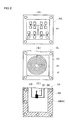
- FIG. 1 is a sectional view showing the configuration of an FM radar module according to one embodiment of the present invention.
- This FM radar module is so constructed that a planar array antenna PA commonly used for transmission and reception and a transmitter-receiver section TR for supplying an FM signal to be radiated from this planar array antenna and for receiving a reflected signal, are vertically layered via a signal delay section DL in an intermediate layer on which a delay line d is formed.
- An input signal to or an output signal from an MMIC (monolithic microwave integrated circuit) of the transmitter-receiver section TR is input or output through a terminal T1.
- An input signal for scanning a beam is input to a terminal T2, by which the planar array antenna PA is controlled.
- the planar array antenna PA has a plurality of patches P11 to P44 provided on the surface of a dielectric board DB. On the rear face of the dielectric board DB, a grounding metal GP is formed. The planar array antenna PA is protected with a radome R from the external environment.
- the planar array antenna PA (the top layer of the layered block), the delay section DL (the intermediate layer), and the transmitter-receiver section TR (the bottom layer) are constructed as shown in the respective plan views of FIGS. 2 (A), (B), and (C). Between the planar array antenna PA of the top layer and one terminal of the delay line d forming the signal delay section DL of the intermediate layer, a high frequency connection is achieved via a pin P1. Between the other terminal of the delay line d and the transmitter-receiver section TR of the bottom layer, a high frequency connection is achieved via a pin P2.
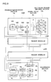
- the FM radar module according to the embodiment shown in FIGS. 1 and 2 may correspond, for example, to one of four FM radar modules LM1 to LM4 constituting a car-mounted FM radar system shown in the block diagram of FIG. 3.
- the car-mounted FM radar system shown in FIG. 3 comprises four FM radar modules LM1 to LM4 and a processing section block PS for controlling each FM radar module, for processing a signal including obstacle information, and for issuing an alarm.
- each of the FM radar modules LM1 to LM4 comprises a transmitter-receiver section TR, including an FM signal generator M1, in the bottom layer, a signal delay section DL, including a delay line d, in the intermediate layer, and a multibeam planar antenna section PA, including four antenna portions Al to A4, in the top layer.
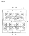
- the planar array antenna PA in the top layer includes sixteen patches P11 to P44 of rectangular shape arranged on the dielectric board DB on the rear face of which a grounding metal is formed. At the centre of the dielectric board DB, a power section P corresponding to the tip part of the pin P1 is formed. A supply line SO, S1 to S4 of microstrip type for connecting this power section P and each patch is formed on the dielectric board DB.
- the sixteen patches P11 to P44 form four antenna portions A1, A2, A3, and A4 for radiating beams of different tilt angles set in accordance with a difference in the length of the supply lines to them.
- the right lower antenna portion A1 comprises two left patches P11, P12 of the same supply line length measured from the power section P, and two right patches P13, P14 of a supply line length longer by L1 than the two left patches, P11, P12.
- the right upper antenna portion A2 comprises two left patches P21, P22 of the same supply line length measured from the power section P, and two right patches P23, P24 of a supply line length longer by L2 than the two left patches P21, P22.
- the left upper antenna portion A3 comprises two right patches P31, P32 of the same supply line length measured from the power section P, and two left patches P33, P34 of a supply line length longer by L3 than the two right patches P31, P32.
- the left lower antenna portion A4 comprises two right patches P41, P42 of the same supply line length measured from the power section P, and two left patches P43, P44 of a supply line length longer by L4 than the two right patches P41, P42.
- Power supply from the power section P to the antenna portion A1 is performed through microstrip supply lines S0 and S1, while power supply from the power section P to the antenna portion A2 is performed through supply lines S0 and S2.
- Power supply from the power section P to the antenna portion A3 and to the antenna section A4 is performed through supply lines S0 and S3 and through supply lines S0 and S4, respectively.
- a bias circuit for each PIN diode is formed including bias input terminals V0 and V1 to V4, and low-pass filters F0 and F1 to F4 on the dielectric board DB. That is, a positive voltage is always applied to a common bias input terminal V0, while either a higher positive voltage than that applied to the terminal V0 or ground (zero) voltage is selectively applied to each of the bias input terminals V1 to V4. This selective voltage is supplied from a timing control circuit P3 in the processing section PS of FIG. 3 through a terminal T2 of FIG. 1.
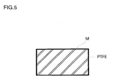
- the delay line d constituting a signal delay section DL in the intermediate layer of the FM radar module, comprises a resin waveguide of spiral shape.
- This resin waveguide has been newly made by the inventors for an FM radar module according to the present embodiment on an experimental basis, and has a sectional shape shown in FIG.5.
- the resin waveguide is made of polytetrafluoroethylene (PTFE), has a rectangular section and comprises metal foil deposited on the surface of a rod-shaped dielectric line by plating.
- the aspect ratio of the section of the dielectric line is approximately 1:2, and when the frequency of an FM signal to be delayed is 60 GHz, the transverse width is 3.8 mm, smaller than that needed by a normal waveguide (5.8 mm). Because of being smaller in size than a normal waveguide and elastic, this resin waveguide has advantages in that a delay line of still smaller size can be implemented with a high density winding.
- the passing loss in this resin waveguide is approximately 3 dB/m in a straight line when the signal frequency is 60 GHz. However, bending at a small radius of curvature increases the passing loss to on the order of 4 dB/m. This value of passing loss is greater than a value of a waveguide without dielectric loss (approximately 1.2 dB/m), but rather smaller than a value of a microstrip line (approximately 7 dB/m).
- a resin waveguide formed by depositing metal foil on the surface of a rod-like body made of polytetrafluoroethylene (PTFE) or the like, is its elasticity and accordingly its delay time can be made longer by implementing a longer dielectric line in a dense spiral shape as shown in FIGS. 1 and 2(B).
- PTFE polytetrafluoroethylene
- the transmitter-receiver section TR in the bottom layer, comprises an FM signal generation circuit M1, a directional coupler M2, an amplifier M3, a circulator M4, and a mixer M5.
- this transmitter-receiver section TR is made as a monolithic microwave integrated circuit (MMIC) and housed in a package.
- An FM signal is input to or output from this package through the pin P2
- a timing signal or connection control instruction is input from the processing section PS in FIG. 3 through signal lines B1, B2, and DC operational power is supplied through a power supply line VB.
- a construction of hybrid microintegration may be employed by omitting it from the objects of the MMIC and attaching it to the outside of other parts made into the MMIC.
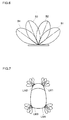
- each FM radar module radiate four beams B1 to B4 of different directions as shown in FIG.6.
- the antenna sections A1 to A4 of each FM radar module have mutually different tilt angles, they radiate four beams B1 to B4 of different directions as shown in FIG.6.
- one of the four beams B1, B2, B3 and B4 is radiated in sequence for a predetermined period from one of the four antenna portions A1, A2, A3 and A4 by making one of the four PIN diodes D1, D2, D3 and D4 conductive in the same sequence for a predetermined period, and if each wave reflected from an object is propagated along a reverse route to the power section P, then beam scanning is carried out in the four different directions with these planar array antennas.
- Each of the radar modules LM1 to LM4 is installed on the four corners of a car as shown in FIG. 7, with the processing section PS installed at an appropriate position in the car.
- an FM signal generator M1 in the FM radar modules LM1 to LM4 generates an FM signal whose frequency changes for a predetermined period in a sawtooth form in response to timing control signals received from the timing control circuit P3 of the processing section PS.
- Part of the generated FM signal is supplied through the directional coupler M2, amplifier M3, and circulator M4 to the multibeam planar array antenna PA, propagates through one of PIN diodes D1 to D4 to be turned ON/OFF in response to a control signal received from the timing control circuit P3 in the processing section PS, and is radiated from the corresponding one of the antenna portions A1 to A4 to the outside of a car.
- An FM signal radiated from an antenna portion and reflected from an object is received by the corresponding antenna portion and supplied through the delay line d constructed using a resin waveguide and through the circulator M4 to one input terminal of the mixer M5.
- the mixer M5 outputs a beat signal whose frequency increases in accordance with the distance to the object generating the reflected wave.
- the respective beat signal output from each of FM radar modules LM1 to LM4 is supplied to the selector P5 in the processing section PS.
- the beat signals are selectively supplied to an A/D conversion circuit P6 in a time sharing method by the selector P5 in accordance with a radar module specifying signal supplied from the timing control circuit P3.
- a beat signal selected by the selector P5 is converted by the A/D convertor P6 into a digital signal.
- the beat signal converted into a digital signal is divided into frequency spectra in a fast Fourier transform circuit (FFT) P7.
- FFT fast Fourier transform circuit
- a signal processing circuit P1 constructed using the CPU does not only detect information relating to an obstacle by referring to the frequency of the beat signal and compute the position of the obstacle and the relative velocity, but also judges the danger of the obstacle and displays information on the existence of the obstacle, the distance to the obstacle, danger and the like on a display P4.
- the signal processing circuit P1 can also generate a signal for controlling the accelerator and brake of the car.
- each antenna portion comprising four patches was exemplified.
- each antenna portion can comprise a larger appropriate number of patches than four.
- an FM radar module for radiating an FM signal was taken as an example for description of the present invention, but the present invention is applicable also to a pulse radar module for radiating a pulse signal.
- a radar module presents a stereographic structure in which a planar array antenna commonly used for transmission and reception and a transmitter-receiver section are layered via an intermediate layer in which a delay line is formed, and thus has advantages in that the function of close distance detection can be implemented under a small-sized structure.
- a planar array antenna commonly used for transmission and reception comprises a plurality of antenna portions that can be selectively connected through the above delay line to the transmitter-receiver section.
- a single transmitter-receiver section is used in common with a plurality of antenna portions, so that the production cost is greatly reduced with a great decrease in the number of parts and miniaturization can also be implemented.
Abstract
Description
- The present invention relates to a vehicle-mounted radar system and radar modules constituent thereof, and in particular to a small-sized and low production cost radar module and radar system.
- A car-mounted radar system mounted on a car, such as a passenger car, is utilized in combination with an alarm device or display device for collision avoidance. In such a car-mounted radar system, detection over a short distance on the order of tens of centimetres is required in order to warn of for example a rear-end impact over a short distance between cars during traffic congestion, or of near collisions when putting a car into a garage. In such cases, FM radar is more suitable than pulse radar. Also, in miniaturizing a module, it is preferable to use millimetre electromagnetic waves of high frequency. Such a millimetre wave FM radar system is disclosed in the specifications of United States patents 5,181,037 and 5,229,774.
- Generally, in an FM radar system, the frequency of a beat signal is arranged to rise in proportion to the distance to an object reflecting the wave. Accordingly, for shorter distances to an object, the frequency of a beat signal lowers and becomes undetectable due to 1/f noise which is generated in a mixer. In an FM radar system according to the prior art mentioned above, the effect of 1/f noise is reduced by raising the frequency of the beat signal, by employing a heterodyne method for modifying the frequency of a local signal, or by using a delay line. However, a heterodyne method requires a local oscillator used for frequency conversion and accordingly is expensive, whereas the use of a delay circuit increases the size of the radar module.
- Furthermore, an FM radar system according to the prior art mentioned above is arranged to switch a transmitter step multiplier, a circulator, antennas used in common for transmission and reception, a mixer and a receiver step multiplier, which constitute each FM radar module, by a synchronous operation between a transmitter side switch and a receiver side switch. Thus, as many transmitter-receiver sections as antennas are necessary, thereby increasing the number of parts so that the whole FM module is not only large in size but production costs are also increased considerably.
- It is one object of the present invention to provide a small-sized and low-production-cost radar module comprising few parts, and a radar system using this radar module, by implementing an arrangement in which a transmitter-receiver section is used in common with a plurality of antennas.
- In a radar module according to the present invention, a planar array antenna used in common for transmission and reception, and a transmitter-receiver section for supplying a radiative signal to this array antenna and receiving a reflected signal, are layered via an intermediate layer on which a delay section made of a delay line is formed. According to a preferred embodiment of the present invention, said planar array antenna comprises a plurality of antenna portions used in common for transmission and reception, and a selective connection section for selectively connecting each of these antenna portions via said delay line to said transmitter-receiver section.
- A delay line implemented with a microstrip line or the like may be provided for improving detection at close quarters by seemingly moving an obstacle to be detected to the front of the car and raising the frequency of a beat signal. This delay line needs to be typically as long as tens of centimetres. By employing a fold back structure, such as a meander line, and a spiral structure, shortening the length of a delay line is performed but is limited in itself. According to the present invention, the size is greatly reduced by placing a delay line between a planar array antenna and a transmitter-receiver section in built layers rather than by placing a delay line in the same plane as with a planar array antenna and a transmitter-receiver section. According to a preferred embodiment of the present invention, a low-loss resin waveguide newly developed by the present inventor is employed as a delay line.
- According to a more preferred embodiment of the present invention, a plurality of antenna portions used in common for transmission and reception are selectively connected to a transmitter-receiver section under the control of a selective connection section. Accordingly, one transmitter-receiver section, including an amplifier, circulator and mixer, is enough for this and thus the number of parts and the space is greatly reduced.
- Embodiments of the present invention will now be described, by way of example only, with reference to the accompanying drawings, in which:
- FIG. 1 is a sectional view showing the configuration of an FM radar module according to one embodiment of the present invention;
- FIG. 2 is a plan view showing the constitution of each layer of the FM radar module shown in FIG. 1 (A showing the planar array antenna PA; B showing the delay section DL; and C showing the transmitter-receiver section TR);
- FIG. 3 is a block diagram showing one example of a typical FM radar system including FM radar modules as shown in FIGS. 1 and 2;
- FIG. 4 is a plan view showing the planar array antenna PA in the top layer shown in FIGS. 1 and 2 (A);
- FIG. 5 is a sectional view showing one example of a resin waveguide constituting the delay section DL in the intermediate layer shown in FIGS. 1 and 2(B);
- FIG. 6 is a conceptual drawing showing one example of beam patterns B1 to B4 of electromagnetic waves radiated from each of the antenna portions A1 to A4 shown in FIG. 3; and
- FIG. 7 is a conceptual drawing showing the disposition and one example of a beam pattern of four radar modules LM1 to LM4 included in the car-mounted FM radar system shown in FIG. 3
- FIG. 1 is a sectional view showing the configuration of an FM radar module according to one embodiment of the present invention. This FM radar module is so constructed that a planar array antenna PA commonly used for transmission and reception and a transmitter-receiver section TR for supplying an FM signal to be radiated from this planar array antenna and for receiving a reflected signal, are vertically layered via a signal delay section DL in an intermediate layer on which a delay line d is formed. An input signal to or an output signal from an MMIC (monolithic microwave integrated circuit) of the transmitter-receiver section TR is input or output through a terminal T1. An input signal for scanning a beam is input to a terminal T2, by which the planar array antenna PA is controlled. The planar array antenna PA has a plurality of patches P11 to P44 provided on the surface of a dielectric board DB. On the rear face of the dielectric board DB, a grounding metal GP is formed. The planar array antenna PA is protected with a radome R from the external environment.
- The planar array antenna PA (the top layer of the layered block), the delay section DL (the intermediate layer), and the transmitter-receiver section TR (the bottom layer) are constructed as shown in the respective plan views of FIGS. 2 (A), (B), and (C). Between the planar array antenna PA of the top layer and one terminal of the delay line d forming the signal delay section DL of the intermediate layer, a high frequency connection is achieved via a pin P1. Between the other terminal of the delay line d and the transmitter-receiver section TR of the bottom layer, a high frequency connection is achieved via a pin P2.
- The FM radar module according to the embodiment shown in FIGS. 1 and 2 may correspond, for example, to one of four FM radar modules LM1 to LM4 constituting a car-mounted FM radar system shown in the block diagram of FIG. 3. The car-mounted FM radar system shown in FIG. 3 comprises four FM radar modules LM1 to LM4 and a processing section block PS for controlling each FM radar module, for processing a signal including obstacle information, and for issuing an alarm. As represented by FM radar module LM1, each of the FM radar modules LM1 to LM4 comprises a transmitter-receiver section TR, including an FM signal generator M1, in the bottom layer, a signal delay section DL, including a delay line d, in the intermediate layer, and a multibeam planar antenna section PA, including four antenna portions Al to A4, in the top layer.
- As shown in the enlarged plan view of FIG. 4, the planar array antenna PA in the top layer, includes sixteen patches P11 to P44 of rectangular shape arranged on the dielectric board DB on the rear face of which a grounding metal is formed. At the centre of the dielectric board DB, a power section P corresponding to the tip part of the pin P1 is formed. A supply line SO, S1 to S4 of microstrip type for connecting this power section P and each patch is formed on the dielectric board DB. The sixteen patches P11 to P44 form four antenna portions A1, A2, A3, and A4 for radiating beams of different tilt angles set in accordance with a difference in the length of the supply lines to them.
- The right lower antenna portion A1 comprises two left patches P11, P12 of the same supply line length measured from the power section P, and two right patches P13, P14 of a supply line length longer by L1 than the two left patches, P11, P12. The right upper antenna portion A2 comprises two left patches P21, P22 of the same supply line length measured from the power section P, and two right patches P23, P24 of a supply line length longer by L2 than the two left patches P21, P22.
- Similarly, the left upper antenna portion A3 comprises two right patches P31, P32 of the same supply line length measured from the power section P, and two left patches P33, P34 of a supply line length longer by L3 than the two right patches P31, P32. The left lower antenna portion A4 comprises two right patches P41, P42 of the same supply line length measured from the power section P, and two left patches P43, P44 of a supply line length longer by L4 than the two right patches P41, P42.
- Power supply from the power section P to the antenna portion A1 is performed through microstrip supply lines S0 and S1, while power supply from the power section P to the antenna portion A2 is performed through supply lines S0 and S2. Power supply from the power section P to the antenna portion A3 and to the antenna section A4 is performed through supply lines S0 and S3 and through supply lines S0 and S4, respectively.
- Between the supply line SO and the individual supply lines S1 to S4, are provided respective PIN diodes D1, D2, D3 and D4 excellent in high frequency characteristics. A bias circuit for each PIN diode is formed including bias input terminals V0 and V1 to V4, and low-pass filters F0 and F1 to F4 on the dielectric board DB. That is, a positive voltage is always applied to a common bias input terminal V0, while either a higher positive voltage than that applied to the terminal V0 or ground (zero) voltage is selectively applied to each of the bias input terminals V1 to V4. This selective voltage is supplied from a timing control circuit P3 in the processing section PS of FIG. 3 through a terminal T2 of FIG. 1. When ground voltage is applied to any of the bias input terminals V1 to V4, the corresponding one of the PIN diodes D1 to D4 becomes conductive so that the supply line SO and the corresponding one of the supply lines S1 to S4 are electrically connected and thus high frequency power is supplied from the power section P to the corresponding one of the antenna portions A1 to A4.
- The delay line d, constituting a signal delay section DL in the intermediate layer of the FM radar module, comprises a resin waveguide of spiral shape. This resin waveguide has been newly made by the inventors for an FM radar module according to the present embodiment on an experimental basis, and has a sectional shape shown in FIG.5. The resin waveguide is made of polytetrafluoroethylene (PTFE), has a rectangular section and comprises metal foil deposited on the surface of a rod-shaped dielectric line by plating. The aspect ratio of the section of the dielectric line is approximately 1:2, and when the frequency of an FM signal to be delayed is 60 GHz, the transverse width is 3.8 mm, smaller than that needed by a normal waveguide (5.8 mm). Because of being smaller in size than a normal waveguide and elastic, this resin waveguide has advantages in that a delay line of still smaller size can be implemented with a high density winding.
- The passing loss in this resin waveguide is approximately 3 dB/m in a straight line when the signal frequency is 60 GHz. However, bending at a small radius of curvature increases the passing loss to on the order of 4 dB/m. This value of passing loss is greater than a value of a waveguide without dielectric loss (approximately 1.2 dB/m), but rather smaller than a value of a microstrip line (approximately 7 dB/m). The feature of a resin waveguide, formed by depositing metal foil on the surface of a rod-like body made of polytetrafluoroethylene (PTFE) or the like, is its elasticity and accordingly its delay time can be made longer by implementing a longer dielectric line in a dense spiral shape as shown in FIGS. 1 and 2(B). Incidentally, since the passing loss increases with smaller radius of curvature, employing a helical structure in which all parts are of the same radius of curvature enables a reduction in passing loss in place of a spiral structure in which the radius of curvature decreases for the inner part.
- As represented by the transmitter-receiver section LM1 in FIG. 3, the transmitter-receiver section TR, in the bottom layer, comprises an FM signal generation circuit M1, a directional coupler M2, an amplifier M3, a circulator M4, and a mixer M5. As shown in FIG. 2(C), this transmitter-receiver section TR is made as a monolithic microwave integrated circuit (MMIC) and housed in a package. An FM signal is input to or output from this package through the pin P2, a timing signal or connection control instruction is input from the processing section PS in FIG. 3 through signal lines B1, B2, and DC operational power is supplied through a power supply line VB. Incidentally, as for a circulator M4, which is relatively difficult to be made into a MMIC, a construction of hybrid microintegration may be employed by omitting it from the objects of the MMIC and attaching it to the outside of other parts made into the MMIC.
- As the antenna sections A1 to A4 of each FM radar module have mutually different tilt angles, they radiate four beams B1 to B4 of different directions as shown in FIG.6. Thus, if one of the four beams B1, B2, B3 and B4 is radiated in sequence for a predetermined period from one of the four antenna portions A1, A2, A3 and A4 by making one of the four PIN diodes D1, D2, D3 and D4 conductive in the same sequence for a predetermined period, and if each wave reflected from an object is propagated along a reverse route to the power section P, then beam scanning is carried out in the four different directions with these planar array antennas. Each of the radar modules LM1 to LM4 is installed on the four corners of a car as shown in FIG. 7, with the processing section PS installed at an appropriate position in the car.
- Referring to FIG. 3, an FM signal generator M1 in the FM radar modules LM1 to LM4 generates an FM signal whose frequency changes for a predetermined period in a sawtooth form in response to timing control signals received from the timing control circuit P3 of the processing section PS. Part of the generated FM signal is supplied through the directional coupler M2, amplifier M3, and circulator M4 to the multibeam planar array antenna PA, propagates through one of PIN diodes D1 to D4 to be turned ON/OFF in response to a control signal received from the timing control circuit P3 in the processing section PS, and is radiated from the corresponding one of the antenna portions A1 to A4 to the outside of a car. An FM signal radiated from an antenna portion and reflected from an object is received by the corresponding antenna portion and supplied through the delay line d constructed using a resin waveguide and through the circulator M4 to one input terminal of the mixer M5.
- To the other terminal of the mixer M5, part of the FM signal generated in the FM signal generator M1 is supplied through the coupler M2. Thus, the mixer M5 outputs a beat signal whose frequency increases in accordance with the distance to the object generating the reflected wave. The respective beat signal output from each of FM radar modules LM1 to LM4 is supplied to the selector P5 in the processing section PS. The beat signals are selectively supplied to an A/D conversion circuit P6 in a time sharing method by the selector P5 in accordance with a radar module specifying signal supplied from the timing control circuit P3. A beat signal selected by the selector P5 is converted by the A/D convertor P6 into a digital signal. The beat signal converted into a digital signal is divided into frequency spectra in a fast Fourier transform circuit (FFT) P7. A signal processing circuit P1 constructed using the CPU does not only detect information relating to an obstacle by referring to the frequency of the beat signal and compute the position of the obstacle and the relative velocity, but also judges the danger of the obstacle and displays information on the existence of the obstacle, the distance to the obstacle, danger and the like on a display P4. Incidentally, the signal processing circuit P1 can also generate a signal for controlling the accelerator and brake of the car.
- Heretofore, a case of setting the tilt angles right-to-left was exemplified. However, setting the tilt angles front-to-back or setting the tilt angles right-to-left and front-to-back in combination is also possible.
- Also, the case of each antenna portion comprising four patches was exemplified. However, according to need, for example, for sharpening the directional characteristic, each antenna portion can comprise a larger appropriate number of patches than four.
- Furthermore, beam scanning by radiating an electromagnetic wave from only one of a plurality of antenna portions was described. However, the present invention is applicable to changing the synthetic directional characteristic by radiating electric waves from any two of the antenna portions.
- Also, a structure of implementing a delay line for an FM signal by using a resin waveguide of small passing loss was exemplified. However, when an increase in passing loss is allowable, using a delay line of microstrip type or triplet type is also possible in place of a dielectric line.
- Also, an FM radar module for radiating an FM signal was taken as an example for description of the present invention, but the present invention is applicable also to a pulse radar module for radiating a pulse signal.
- As described in detail, a radar module according to the present invention presents a stereographic structure in which a planar array antenna commonly used for transmission and reception and a transmitter-receiver section are layered via an intermediate layer in which a delay line is formed, and thus has advantages in that the function of close distance detection can be implemented under a small-sized structure.
- Also, according to a preferred embodiment of the present invention, a planar array antenna commonly used for transmission and reception comprises a plurality of antenna portions that can be selectively connected through the above delay line to the transmitter-receiver section. Thus, a single transmitter-receiver section is used in common with a plurality of antenna portions, so that the production cost is greatly reduced with a great decrease in the number of parts and miniaturization can also be implemented.
Claims (20)
- A radar module comprising:a planar array antenna; anda transmitter-receiver section for supplying a signal to be radiated by said planar array antenna and receiving a receive signal from the planar array antenna; whereina delay line is inserted between said planar array antenna and said transmitter-receiver section,said delay line being disposed on the rear face of a substrate of said planar array antenna.
- The radar module of Claim 1, wherein said planar array antenna comprises:a plurality of antenna portions; anda selective connection section for selectively connecting each antenna portion through said delay line to said transmitter-receiver section.
- The radar module of Claim 2, wherein said plurality of antenna portions have different respective tilt angles.
- The radar module of any of Claims 1 to 3, wherein said transmitter-receiver section comprises:an FM signal generation circuit for generating FM signals to be radiated from said planar array antenna; anda mixer for mixing a receive signal from said planar array antenna with part of the FM signal generated in said FM signal generation circuit to generate a beat signal.
- The radar module of any of Claims 1 to 4, wherein said delay line comprises a waveguide in which a metal layer covers a dielectric of rectangular section.
- The radar module of Claim 5, wherein said waveguide is formed in a spiral.
- A radar module comprising:a planar array antenna for transmitting or receiving a high-frequency signal; anda transmitter-receiver circuit for supplying a high-frequency signal to or receiving a high-frequency signal from said planar array antenna; whereina delay line made of a dielectric of rectangular section covered over four peripheral sides with metal is inserted between said planar array antenna and said transmitter-receiver circuit.
- A radar module for transmitting and receiving a high-frequency signal to detect an object, comprising:a scan type planar antenna disposed on a dielectric substrate for scanning a high-frequency signal;an MMIC (Monolithic Microwave IC) including a high-frequency signal generator and receiver for receiving a signal reflected from an object; andmeans for supplying a high-frequency signal to the planar antenna from the rear face of said planar antenna with said MMIC disposed on the rear face of the planar antenna.
- The radar module of Claim 8, wherein said scan-type planar antenna is arranged in a plane and comprises a plurality of rectangular patches disposed on a dielectric base board, and switch means for selectively supplying a high-frequency signal to each of the patches.
- The radar module of Claim 8 or 9, wherein said scan-type planar antenna is a time-sharing scan-type planar antenna.
- The radar module of any of Claims 8, 9 or 10, further comprising a delay line for temporarily delaying a transmit or receive signal.
- A radar system for detecting the position of an object by transmitting a high-frequency signal to said object and receiving a signal reflected from said object, comprising:a plurality of radar modules, each comprising an MMIC including a high-frequency signal generator and a mixer for generating a beat signal from a signal reflected from said object, and a scan-type planar antenna connected to said MMIC for radiating and scanning a high-frequency signal;a selector circuit for selecting an output signal from one of said radar modules;an A/D converter for converting the signal selected in said selector circuit into a digital signal; anda signal processing circuit for analyzing the frequency of a receive signal based on said digital signal to obtain information on said object.
- The radar system of Claim 12, wherein said signal processing circuit comprises a timing control circuit for controlling the scanning of said radar modules.
- The radar system of Claim 12 or 13, wherein the plurality of radar modules arc placed around a vehicle.
- The radar system of Claim 12, 13 or 14, wherein said scan-type planar antenna is supplied from the rear with a signal to be radiated.
- The radar system of any of Claims 12 to 15, wherein said scan-type planar antenna performs time-sharing beam scanning.
- The radar system of any of Claims 12 to 16, wherein each radar module has a delay line provided between the planar antenna and a transmitter-receiver circuit.
- The radar system of Claim 17 or 18, wherein said delay line is a dielectric waveguide.
- The radar system of Claim 17 or 18, wherein said delay line is of spiral formation.
- The radar system of any of Claims 12 to 19, wherein the high-frequency signal to be transmitted to the object is an FM signal.
Applications Claiming Priority (3)
| Application Number | Priority Date | Filing Date | Title |
|---|---|---|---|
| JP27458694A JP3308734B2 (en) | 1994-10-13 | 1994-10-13 | Radar module |
| JP274586/94 | 1994-10-13 | ||
| JP27458694 | 1994-10-13 |
Publications (3)
| Publication Number | Publication Date |
|---|---|
| EP0707220A2 true EP0707220A2 (en) | 1996-04-17 |
| EP0707220A3 EP0707220A3 (en) | 1996-12-04 |
| EP0707220B1 EP0707220B1 (en) | 2002-06-05 |
Family
ID=17543811
Family Applications (1)
| Application Number | Title | Priority Date | Filing Date |
|---|---|---|---|
| EP95307007A Expired - Lifetime EP0707220B1 (en) | 1994-10-13 | 1995-10-03 | Radar module and radar system |
Country Status (4)
| Country | Link |
|---|---|
| US (1) | US5657024A (en) |
| EP (1) | EP0707220B1 (en) |
| JP (1) | JP3308734B2 (en) |
| DE (1) | DE69526899T2 (en) |
Cited By (17)
| Publication number | Priority date | Publication date | Assignee | Title |
|---|---|---|---|---|
| EP0800093A1 (en) * | 1996-04-03 | 1997-10-08 | Honda Giken Kogyo Kabushiki Kaisha | Radar module and MMIC package for use in such radar module |
| EP0806681A2 (en) * | 1996-05-09 | 1997-11-12 | Honda Giken Kogyo Kabushiki Kaisha | Multibeam FM radar system |
| EP0831553A2 (en) * | 1996-09-18 | 1998-03-25 | Honda Giken Kogyo Kabushiki Kaisha | Antenna device |
| DE19705834A1 (en) * | 1997-02-15 | 1998-08-20 | Itt Mfg Enterprises Inc | Distance measurement device for motor vehicles which operates with microwaves |
| EP0867972A1 (en) * | 1997-03-27 | 1998-09-30 | Denso Corporation | Aperture antenna and radar system using same |
| EP0898174A1 (en) * | 1997-08-18 | 1999-02-24 | Fujitsu Limited | Radar apparatus |
| EP0984300A2 (en) * | 1998-09-02 | 2000-03-08 | Mannesmann VDO Aktiengesellschaft | Parking-aid device for a motor vehicle |
| EP1304764A1 (en) * | 2001-10-19 | 2003-04-23 | B.E.R. Group S.A. | Planar antenna |
| EP1486796A2 (en) * | 2003-06-09 | 2004-12-15 | Fujitsu Ten Limited | Radar device with switch matrix for adaptive beamforming in receive path and switching of transmit path |
| EP1431773A3 (en) * | 2002-12-20 | 2005-02-09 | Robert Bosch Gmbh | Scanning radar |
| EP1920499A2 (en) * | 2005-08-10 | 2008-05-14 | Navini Networks, Inc. | Microstrip antenna with integral feed and antenna structures |
| EP2009463A2 (en) | 2007-06-21 | 2008-12-31 | Diehl BGT Defence GmbH & Co.KG | Safety device for an automatic self-protection system |
| WO2009080491A1 (en) * | 2007-12-21 | 2009-07-02 | Hella Kgaa Hueck & Co. | Radar sensor arrangement |
| GB2473663A (en) * | 2009-09-21 | 2011-03-23 | Cambridge Consultants | Radar |
| FR2969398A1 (en) * | 2010-12-20 | 2012-06-22 | St Microelectronics Sa | INTEGRATED EMITTER-RECEIVER IN MILLIMETER WAVES |
| WO2016025136A1 (en) | 2014-08-14 | 2016-02-18 | Google Inc. | Modular planar multi-sector 90 degrees fov radar antenna architecture |
| RU2645734C1 (en) * | 2016-10-04 | 2018-02-28 | Акционерное общество "Научно-исследовательский институт Приборостроения имени В.В. Тихомирова" | Method of radar-objective detection of dangerous obstacles at low-altitude mission of the flighting apparatus |
Families Citing this family (41)
| Publication number | Priority date | Publication date | Assignee | Title |
|---|---|---|---|---|
| JP2782053B2 (en) | 1995-03-23 | 1998-07-30 | 本田技研工業株式会社 | Radar module and antenna device |
| US5943017A (en) * | 1995-12-13 | 1999-08-24 | Ail Systems, Inc. | Dual near-field focused antenna array |
| US5933109A (en) * | 1996-05-02 | 1999-08-03 | Honda Giken Kabushiki Kaisha | Multibeam radar system |
| US6266010B1 (en) | 1999-09-16 | 2001-07-24 | Lockheed Martin Corporation | Method and apparatus for transmitting and receiving signals using electronic beam forming |
| US6198438B1 (en) * | 1999-10-04 | 2001-03-06 | The United States Of America As Represented By The Secretary Of The Air Force | Reconfigurable microstrip antenna array geometry which utilizes micro-electro-mechanical system (MEMS) switches |
| US6542119B2 (en) * | 2000-05-23 | 2003-04-01 | Varitek Industries, Inc. | GPS antenna array |
| JP3964873B2 (en) * | 2001-11-09 | 2007-08-22 | 株式会社日立製作所 | In-vehicle millimeter wave radar system |
| DE10163653A1 (en) * | 2001-12-21 | 2003-07-03 | Bosch Gmbh Robert | Device for radar system e.g. for speed control in vehicle, uses demodulated reception signals specifically as input signals for device |
| JP3858801B2 (en) * | 2002-10-10 | 2006-12-20 | 株式会社日立製作所 | In-vehicle millimeter-wave radar device, millimeter-wave radar module, and manufacturing method thereof |
| US6885345B2 (en) * | 2002-11-14 | 2005-04-26 | The Penn State Research Foundation | Actively reconfigurable pixelized antenna systems |
| US7256753B2 (en) * | 2003-01-14 | 2007-08-14 | The Penn State Research Foundation | Synthesis of metamaterial ferrites for RF applications using electromagnetic bandgap structures |
| DE102004042661A1 (en) * | 2004-04-13 | 2005-11-03 | Mso Messtechnik Und Ortung Gmbh | Motor vehicle with device for contactlessly detecting a motor vehicle' self-movement has radar unit with planar antenna |
| JP4447389B2 (en) * | 2004-07-09 | 2010-04-07 | 本田技研工業株式会社 | Radar apparatus and vehicle control apparatus including the radar apparatus |
| WO2006027828A1 (en) * | 2004-09-07 | 2006-03-16 | Mitsubishi Denki Kabushiki Kaisha | Electric power distributing apparatus, electric power combining apparatus, mono-pulse signal combining circuit, array antenna power supplying circuit, and beam shaping circuit |
| JP4101814B2 (en) | 2005-03-15 | 2008-06-18 | 富士通株式会社 | High frequency module |
| JP4725582B2 (en) * | 2005-10-27 | 2011-07-13 | 株式会社村田製作所 | High frequency module |
| PL1989570T3 (en) * | 2006-01-17 | 2017-02-28 | Teledyne Australia Pty Ltd. | Surveillance apparatus and method |
| CN101042435B (en) * | 2006-03-23 | 2011-03-23 | 欧姆龙汽车电子株式会社 | Single pulse radar device |
| WO2008134815A1 (en) * | 2007-05-04 | 2008-11-13 | Teledyne Australia Pty Ltd. | Collision avoidance system and method |
| JP2009058450A (en) * | 2007-08-31 | 2009-03-19 | Fujitsu Ten Ltd | Unit chassis of radar device |
| PL2191292T3 (en) * | 2007-09-19 | 2019-09-30 | Teledyne Australia Pty Ltd | Imaging system and method |
| US7830301B2 (en) * | 2008-04-04 | 2010-11-09 | Toyota Motor Engineering & Manufacturing North America, Inc. | Dual-band antenna array and RF front-end for automotive radars |
| US8022861B2 (en) * | 2008-04-04 | 2011-09-20 | Toyota Motor Engineering & Manufacturing North America, Inc. | Dual-band antenna array and RF front-end for mm-wave imager and radar |
| DE102008038365A1 (en) * | 2008-07-02 | 2010-01-07 | Adc Automotive Distance Control Systems Gmbh | Vehicle radar system and method for determining a position of at least one object relative to a vehicle |
| JP5635259B2 (en) * | 2008-12-19 | 2014-12-03 | トヨタ モーター エンジニアリング アンド マニュファクチャリング ノース アメリカ,インコーポレイティド | Dual-band antenna array and RF front end for automotive radar |
| US8378759B2 (en) | 2009-01-16 | 2013-02-19 | Toyota Motor Engineering & Manufacturing North America, Inc. | First and second coplanar microstrip lines separated by rows of vias for reducing cross-talk there between |
| WO2010085846A2 (en) | 2009-01-30 | 2010-08-05 | Teledyne Australia Pty Ltd | Apparatus and method for assisting vertical takeoff vehicles |
| JP5726852B2 (en) | 2009-04-06 | 2015-06-03 | コンティ テミック マイクロエレクトロニック ゲゼルシャフト ミットベシュレンクテル ハフツングConti Temic microelectronic GmbH | Radar system and method having apparatus for separating transmitted signal and received signal and suppressing jamming radiation |
| FR2969397B1 (en) | 2010-12-20 | 2013-09-06 | St Microelectronics Crolles 2 | INTEGRATED EMITTER-RECEIVER IN MILLIMETER WAVES |
| JP6177349B2 (en) * | 2012-12-27 | 2017-08-09 | コリア アドバンスト インスティテュート オブ サイエンスアンド テクノロジーKorea Advanced Institute Of Science And Technology | Chip-to-chip interface using low-power, high-speed multi-channel dielectric waveguide |
| DE102013211712A1 (en) * | 2013-06-20 | 2015-01-08 | Siemens Aktiengesellschaft | Antenna module and device with antenna module |
| DE102014200692A1 (en) * | 2014-01-16 | 2015-07-16 | Robert Bosch Gmbh | PROCESS, ANTENNA ARRANGEMENT, RADAR SYSTEM AND VEHICLE |
| KR102212876B1 (en) * | 2014-04-28 | 2021-02-05 | 엘지이노텍 주식회사 | Radar apparatus |
| DE102014208389A1 (en) * | 2014-05-06 | 2015-11-12 | Robert Bosch Gmbh | Antenna device for a vehicle |
| US20170005416A1 (en) * | 2015-06-30 | 2017-01-05 | Raytheon Company | Multi-beam phased array antenna |
| JP6593444B2 (en) | 2015-09-17 | 2019-10-23 | 株式会社村田製作所 | Communication module with integrated antenna |
| DE102015222884A1 (en) | 2015-11-19 | 2017-05-24 | Conti Temic Microelectronic Gmbh | Radar system with interleaved serial transmission and parallel reception |
| US9828036B2 (en) | 2015-11-24 | 2017-11-28 | Srg Global Inc. | Active grille shutter system with integrated radar |
| JP2019052987A (en) * | 2017-09-19 | 2019-04-04 | トヨタ自動車株式会社 | Vehicle periphery monitoring device |
| DE102018206535A1 (en) * | 2018-04-27 | 2019-10-31 | Robert Bosch Gmbh | Radar sensor device |
| JP7274056B1 (en) * | 2022-03-11 | 2023-05-15 | 三菱電機株式会社 | wiring board |
Citations (2)
| Publication number | Priority date | Publication date | Assignee | Title |
|---|---|---|---|---|
| US5181037A (en) | 1991-02-15 | 1993-01-19 | Honda Giken Kogyo Kabushiki Kaisha | Fm radar system |
| US5229774A (en) | 1991-02-15 | 1993-07-20 | Honda Giken Kogyo Kabushiki Kaisha | FM radar system |
Family Cites Families (6)
| Publication number | Priority date | Publication date | Assignee | Title |
|---|---|---|---|---|
| GB2137449A (en) * | 1983-03-18 | 1984-10-03 | Marconi Co Ltd | Target detection systems |
| US5008678A (en) * | 1990-03-02 | 1991-04-16 | Hughes Aircraft Company | Electronically scanning vehicle radar sensor |
| US5115245A (en) * | 1990-09-04 | 1992-05-19 | Hughes Aircraft Company | Single substrate microwave radar transceiver including flip-chip integrated circuits |
| GB9106110D0 (en) * | 1991-03-22 | 1991-05-08 | Philips Electronic Associated | Doppler radar speed sensor |
| JP2779559B2 (en) * | 1991-09-04 | 1998-07-23 | 本田技研工業株式会社 | Radar equipment |
| US5315303A (en) * | 1991-09-30 | 1994-05-24 | Trw Inc. | Compact, flexible and integrated millimeter wave radar sensor |
-
1994
- 1994-10-13 JP JP27458694A patent/JP3308734B2/en not_active Expired - Fee Related
-
1995
- 1995-10-03 DE DE69526899T patent/DE69526899T2/en not_active Expired - Fee Related
- 1995-10-03 EP EP95307007A patent/EP0707220B1/en not_active Expired - Lifetime
- 1995-10-05 US US08/539,477 patent/US5657024A/en not_active Expired - Lifetime
Patent Citations (2)
| Publication number | Priority date | Publication date | Assignee | Title |
|---|---|---|---|---|
| US5181037A (en) | 1991-02-15 | 1993-01-19 | Honda Giken Kogyo Kabushiki Kaisha | Fm radar system |
| US5229774A (en) | 1991-02-15 | 1993-07-20 | Honda Giken Kogyo Kabushiki Kaisha | FM radar system |
Cited By (36)
| Publication number | Priority date | Publication date | Assignee | Title |
|---|---|---|---|---|
| EP0800093A1 (en) * | 1996-04-03 | 1997-10-08 | Honda Giken Kogyo Kabushiki Kaisha | Radar module and MMIC package for use in such radar module |
| EP0806681A3 (en) * | 1996-05-09 | 1999-11-10 | Honda Giken Kogyo Kabushiki Kaisha | Multibeam FM radar system |
| EP0806681A2 (en) * | 1996-05-09 | 1997-11-12 | Honda Giken Kogyo Kabushiki Kaisha | Multibeam FM radar system |
| EP0831553A2 (en) * | 1996-09-18 | 1998-03-25 | Honda Giken Kogyo Kabushiki Kaisha | Antenna device |
| EP1306925A3 (en) * | 1996-09-18 | 2003-05-14 | Honda Giken Kogyo Kabushiki Kaisha | Antenna device |
| EP1306925A2 (en) * | 1996-09-18 | 2003-05-02 | Honda Giken Kogyo Kabushiki Kaisha | Antenna device |
| EP0831553A3 (en) * | 1996-09-18 | 2000-05-24 | Honda Giken Kogyo Kabushiki Kaisha | Antenna device |
| DE19705834A1 (en) * | 1997-02-15 | 1998-08-20 | Itt Mfg Enterprises Inc | Distance measurement device for motor vehicles which operates with microwaves |
| EP0867972A1 (en) * | 1997-03-27 | 1998-09-30 | Denso Corporation | Aperture antenna and radar system using same |
| US5977904A (en) * | 1997-03-27 | 1999-11-02 | Denso Corporation | Structure of aperture antenna and radar system using same |
| US5940029A (en) * | 1997-08-18 | 1999-08-17 | Fujitsu Limited | Radar apparatus |
| EP0898174A1 (en) * | 1997-08-18 | 1999-02-24 | Fujitsu Limited | Radar apparatus |
| EP0984300A2 (en) * | 1998-09-02 | 2000-03-08 | Mannesmann VDO Aktiengesellschaft | Parking-aid device for a motor vehicle |
| EP0984300A3 (en) * | 1998-09-02 | 2001-08-08 | Mannesmann VDO Aktiengesellschaft | Parking-aid device for a motor vehicle |
| EP1304764A1 (en) * | 2001-10-19 | 2003-04-23 | B.E.R. Group S.A. | Planar antenna |
| US6700542B2 (en) | 2001-10-19 | 2004-03-02 | B.E.A.S.A. | Planar antenna |
| US7129892B2 (en) | 2001-10-19 | 2006-10-31 | B. E. A. Sa | Planar antenna |
| EP1431773A3 (en) * | 2002-12-20 | 2005-02-09 | Robert Bosch Gmbh | Scanning radar |
| US7119733B2 (en) | 2002-12-20 | 2006-10-10 | Robert Bosch Gmbh | Angle-scanning radar system |
| EP1684087A2 (en) | 2003-06-09 | 2006-07-26 | Fujitsu Ten Limited | Radar device with switch matrix for adaptive beamforming in receive path and switching of transmit path |
| EP1684087A3 (en) * | 2003-06-09 | 2006-08-02 | Fujitsu Ten Limited | Radar device with switch matrix for adaptive beamforming in receive path and switching of transmit path |
| EP1486796A2 (en) * | 2003-06-09 | 2004-12-15 | Fujitsu Ten Limited | Radar device with switch matrix for adaptive beamforming in receive path and switching of transmit path |
| US7173561B2 (en) | 2003-06-09 | 2007-02-06 | Fujitsu Ten Limited | Radar device capable of scanning received reflection waves |
| EP1486796A3 (en) * | 2003-06-09 | 2005-02-02 | Fujitsu Ten Limited | Radar device with switch matrix for adaptive beamforming in receive path and switching of transmit path |
| EP1920499A4 (en) * | 2005-08-10 | 2010-12-15 | Cisco Tech Inc | Microstrip antenna with integral feed and antenna structures |
| EP1920499A2 (en) * | 2005-08-10 | 2008-05-14 | Navini Networks, Inc. | Microstrip antenna with integral feed and antenna structures |
| EP2009463A2 (en) | 2007-06-21 | 2008-12-31 | Diehl BGT Defence GmbH & Co.KG | Safety device for an automatic self-protection system |
| EP2009463A3 (en) * | 2007-06-21 | 2009-07-22 | Diehl BGT Defence GmbH & Co.KG | Safety device for an automatic self-protection system |
| WO2009080491A1 (en) * | 2007-12-21 | 2009-07-02 | Hella Kgaa Hueck & Co. | Radar sensor arrangement |
| GB2473663A (en) * | 2009-09-21 | 2011-03-23 | Cambridge Consultants | Radar |
| GB2473663B (en) * | 2009-09-21 | 2016-11-23 | Aveillant Ltd | Radar Receiver |
| FR2969398A1 (en) * | 2010-12-20 | 2012-06-22 | St Microelectronics Sa | INTEGRATED EMITTER-RECEIVER IN MILLIMETER WAVES |
| WO2016025136A1 (en) | 2014-08-14 | 2016-02-18 | Google Inc. | Modular planar multi-sector 90 degrees fov radar antenna architecture |
| CN107076844A (en) * | 2014-08-14 | 2017-08-18 | 谷歌公司 | 90 degree of many sectors of modularization plane visual field Radar Antenna Structure |
| EP3180638A4 (en) * | 2014-08-14 | 2018-04-04 | Waymo Llc | Modular planar multi-sector 90 degrees fov radar antenna architecture |
| RU2645734C1 (en) * | 2016-10-04 | 2018-02-28 | Акционерное общество "Научно-исследовательский институт Приборостроения имени В.В. Тихомирова" | Method of radar-objective detection of dangerous obstacles at low-altitude mission of the flighting apparatus |
Also Published As
| Publication number | Publication date |
|---|---|
| EP0707220A3 (en) | 1996-12-04 |
| EP0707220B1 (en) | 2002-06-05 |
| JP3308734B2 (en) | 2002-07-29 |
| US5657024A (en) | 1997-08-12 |
| DE69526899T2 (en) | 2002-09-19 |
| DE69526899D1 (en) | 2002-07-11 |
| JPH08114667A (en) | 1996-05-07 |
Similar Documents
| Publication | Publication Date | Title |
|---|---|---|
| EP0707220B1 (en) | Radar module and radar system | |
| JP3302848B2 (en) | In-vehicle radar device | |
| US4742354A (en) | Radar transceiver employing circularly polarized waveforms | |
| JP2779559B2 (en) | Radar equipment | |
| EP0800093B1 (en) | Radar module and MMIC package for use in such radar module | |
| EP1597793B1 (en) | Wideband 2-d electronically scanned array with compact cts feed and mems phase shifters | |
| CN110741273B (en) | Antenna array | |
| US11223112B2 (en) | Inverted microstrip travelling wave patch array antenna system | |
| JPH06232621A (en) | Active transmission phased array antenna | |
| JP2004158911A (en) | Sector antenna system and on-vehicle transmitter-receiver | |
| US20080150819A1 (en) | Radar apparatus | |
| JP7008216B2 (en) | Radar device | |
| US11515639B2 (en) | Method and apparatus for an active radiating and feed structure | |
| CN114784499A (en) | Beam deflection antenna, antenna array, radar sensor and vehicle | |
| EP1932212B1 (en) | Frequency scanning antenna | |
| US11355854B2 (en) | Method and apparatus for reactance control in a transmission line | |
| CN113381174A (en) | Antenna and radar | |
| JPH0897620A (en) | Multi-beam planar array antenna | |
| EP4340126A1 (en) | Antenna unit, radar, and terminal device | |
| CN112368591A (en) | Radar apparatus | |
| WO2023228751A1 (en) | Electronic device | |
| JPH11261332A (en) | Radar device | |
| JP2875509B2 (en) | FM radar equipment | |
| JP2967870B2 (en) | Radar equipment | |
| CN114006175A (en) | Low sidelobe level integrated cavity back slot array antenna system |
Legal Events
| Date | Code | Title | Description |
|---|---|---|---|
| PUAI | Public reference made under article 153(3) epc to a published international application that has entered the european phase |
Free format text: ORIGINAL CODE: 0009012 |
|
| AK | Designated contracting states |
Kind code of ref document: A2 Designated state(s): DE FR GB |
|
| PUAL | Search report despatched |
Free format text: ORIGINAL CODE: 0009013 |
|
| AK | Designated contracting states |
Kind code of ref document: A3 Designated state(s): DE FR GB |
|
| 17P | Request for examination filed |
Effective date: 19970107 |
|
| 17Q | First examination report despatched |
Effective date: 19990917 |
|
| GRAG | Despatch of communication of intention to grant |
Free format text: ORIGINAL CODE: EPIDOS AGRA |
|
| GRAG | Despatch of communication of intention to grant |
Free format text: ORIGINAL CODE: EPIDOS AGRA |
|
| GRAH | Despatch of communication of intention to grant a patent |
Free format text: ORIGINAL CODE: EPIDOS IGRA |
|
| GRAH | Despatch of communication of intention to grant a patent |
Free format text: ORIGINAL CODE: EPIDOS IGRA |
|
| GRAA | (expected) grant |
Free format text: ORIGINAL CODE: 0009210 |
|
| AK | Designated contracting states |
Kind code of ref document: B1 Designated state(s): DE FR GB |
|
| REG | Reference to a national code |
Ref country code: GB Ref legal event code: FG4D |
|
| REF | Corresponds to: |
Ref document number: 69526899 Country of ref document: DE Date of ref document: 20020711 |
|
| ET | Fr: translation filed | ||
| PLBE | No opposition filed within time limit |
Free format text: ORIGINAL CODE: 0009261 |
|
| STAA | Information on the status of an ep patent application or granted ep patent |
Free format text: STATUS: NO OPPOSITION FILED WITHIN TIME LIMIT |
|
| 26N | No opposition filed |
Effective date: 20030306 |
|
| PGFP | Annual fee paid to national office [announced via postgrant information from national office to epo] |
Ref country code: DE Payment date: 20070927 Year of fee payment: 13 |
|
| PGFP | Annual fee paid to national office [announced via postgrant information from national office to epo] |
Ref country code: GB Payment date: 20071003 Year of fee payment: 13 |
|
| REG | Reference to a national code |
Ref country code: FR Ref legal event code: ST Effective date: 20080630 |
|
| PGFP | Annual fee paid to national office [announced via postgrant information from national office to epo] |
Ref country code: FR Payment date: 20061010 Year of fee payment: 12 |
|
| PG25 | Lapsed in a contracting state [announced via postgrant information from national office to epo] |
Ref country code: FR Free format text: LAPSE BECAUSE OF NON-PAYMENT OF DUE FEES Effective date: 20071031 |
|
| GBPC | Gb: european patent ceased through non-payment of renewal fee |
Effective date: 20081003 |
|
| PG25 | Lapsed in a contracting state [announced via postgrant information from national office to epo] |
Ref country code: DE Free format text: LAPSE BECAUSE OF NON-PAYMENT OF DUE FEES Effective date: 20090501 |
|
| PG25 | Lapsed in a contracting state [announced via postgrant information from national office to epo] |
Ref country code: GB Free format text: LAPSE BECAUSE OF NON-PAYMENT OF DUE FEES Effective date: 20081003 |