EP0707827A1 - Fluid filtering device utilizable with gas monitors - Google Patents
Fluid filtering device utilizable with gas monitors Download PDFInfo
- Publication number
- EP0707827A1 EP0707827A1 EP95307005A EP95307005A EP0707827A1 EP 0707827 A1 EP0707827 A1 EP 0707827A1 EP 95307005 A EP95307005 A EP 95307005A EP 95307005 A EP95307005 A EP 95307005A EP 0707827 A1 EP0707827 A1 EP 0707827A1
- Authority
- EP
- European Patent Office
- Prior art keywords
- fluid
- tubular housing
- liquid
- filter element
- housing
- Prior art date
- Legal status (The legal status is an assumption and is not a legal conclusion. Google has not performed a legal analysis and makes no representation as to the accuracy of the status listed.)
- Granted
Links
Images


Classifications
-
- B—PERFORMING OPERATIONS; TRANSPORTING
- B01—PHYSICAL OR CHEMICAL PROCESSES OR APPARATUS IN GENERAL
- B01D—SEPARATION
- B01D46/00—Filters or filtering processes specially modified for separating dispersed particles from gases or vapours
- B01D46/24—Particle separators, e.g. dust precipitators, using rigid hollow filter bodies
- B01D46/2403—Particle separators, e.g. dust precipitators, using rigid hollow filter bodies characterised by the physical shape or structure of the filtering element
- B01D46/2407—Filter candles
-
- A—HUMAN NECESSITIES
- A61—MEDICAL OR VETERINARY SCIENCE; HYGIENE
- A61M—DEVICES FOR INTRODUCING MEDIA INTO, OR ONTO, THE BODY; DEVICES FOR TRANSDUCING BODY MEDIA OR FOR TAKING MEDIA FROM THE BODY; DEVICES FOR PRODUCING OR ENDING SLEEP OR STUPOR
- A61M16/00—Devices for influencing the respiratory system of patients by gas treatment, e.g. mouth-to-mouth respiration; Tracheal tubes
- A61M16/08—Bellows; Connecting tubes ; Water traps; Patient circuits
- A61M16/0816—Joints or connectors
- A61M16/0833—T- or Y-type connectors, e.g. Y-piece
-
- A—HUMAN NECESSITIES
- A61—MEDICAL OR VETERINARY SCIENCE; HYGIENE
- A61M—DEVICES FOR INTRODUCING MEDIA INTO, OR ONTO, THE BODY; DEVICES FOR TRANSDUCING BODY MEDIA OR FOR TAKING MEDIA FROM THE BODY; DEVICES FOR PRODUCING OR ENDING SLEEP OR STUPOR
- A61M16/00—Devices for influencing the respiratory system of patients by gas treatment, e.g. mouth-to-mouth respiration; Tracheal tubes
- A61M16/08—Bellows; Connecting tubes ; Water traps; Patient circuits
- A61M16/0816—Joints or connectors
- A61M16/0841—Joints or connectors for sampling
- A61M16/085—Gas sampling
-
- A—HUMAN NECESSITIES
- A61—MEDICAL OR VETERINARY SCIENCE; HYGIENE
- A61M—DEVICES FOR INTRODUCING MEDIA INTO, OR ONTO, THE BODY; DEVICES FOR TRANSDUCING BODY MEDIA OR FOR TAKING MEDIA FROM THE BODY; DEVICES FOR PRODUCING OR ENDING SLEEP OR STUPOR
- A61M16/00—Devices for influencing the respiratory system of patients by gas treatment, e.g. mouth-to-mouth respiration; Tracheal tubes
- A61M16/10—Preparation of respiratory gases or vapours
- A61M16/105—Filters
- A61M16/106—Filters in a path
- A61M16/1065—Filters in a path in the expiratory path
-
- B—PERFORMING OPERATIONS; TRANSPORTING
- B01—PHYSICAL OR CHEMICAL PROCESSES OR APPARATUS IN GENERAL
- B01D—SEPARATION
- B01D46/00—Filters or filtering processes specially modified for separating dispersed particles from gases or vapours
- B01D46/0027—Filters or filtering processes specially modified for separating dispersed particles from gases or vapours with additional separating or treating functions
- B01D46/003—Filters or filtering processes specially modified for separating dispersed particles from gases or vapours with additional separating or treating functions including coalescing means for the separation of liquid
-
- B—PERFORMING OPERATIONS; TRANSPORTING
- B01—PHYSICAL OR CHEMICAL PROCESSES OR APPARATUS IN GENERAL
- B01D—SEPARATION
- B01D46/00—Filters or filtering processes specially modified for separating dispersed particles from gases or vapours
- B01D46/56—Filters or filtering processes specially modified for separating dispersed particles from gases or vapours with multiple filtering elements, characterised by their mutual disposition
- B01D46/58—Filters or filtering processes specially modified for separating dispersed particles from gases or vapours with multiple filtering elements, characterised by their mutual disposition connected in parallel
Definitions
- the present invention relates to a fluid filtering device and particularly to a filter for separating liquid from gases. More specifically, the present invention is concerned with a filtering device utilizable with a gas analyzer or monitor, having a very limited effect on the response time of the monitor to changes of the gas content and being independent of the orientation of the device or of the field of gravitation acting thereupon.
- Gas filters based on the first technology commonly use flat sheets of hydrophobic microporous membranes embodied within an appropriate housing, whose structure is designed to both collect the trapped liquid and for connection with the analyzers or monitors.
- the gas flows through the filtering media without the wave form of the gas being disturbed. This is required so that the measured changes in time of the gas constitution originate only from the breath under test and not those introduced later by parts of the flow system, which transfers the gas to the measuring region.
- a measure of merit for a filtering device reflecting its ability to freely transfer gases is defined by the response time it invokes. In general, the response time is a measure of response to a change in gas constituent. A long response time will distort the output display even at low breathing rates and such distortion may affect the accuracy of the tested information regarding a patient's health condition displayed on, or recorded by, the analyzer or monitor.
- the filter When working with low gas flow rates, as is typical with capnographs, in order to create a gas filter with minimum distortion to the gas wave form providing short response times, the filter should provide minimal turbulence and resistance to a laminar flow and have no fluid passageways through which the gas passes, which due to shape, size or material thereof, disturb the wave form.
- the shape and size of the fluid passageways must be such that no abrupt changes in dimensions or volume thereof when entering the filter be permitted. Otherwise, the gas entering enlargements in the passageways will possess very different flow rates along the radius perpendicular to the direction of gas flow upstream therefrom. Regions furthest away from the center of the passageways may have very slow flow rates relative to the center.
- porous walls used to either soak up liquid or as a filter media
- a substantial thickness e.g. more than 0.5 mm
- the filtering device of the present invention is especially advantageous for filtering small or minute volumes of fluid, for example, fluids extracted for analysis from neonatals and the aged.
- a fluid filtering device for separating liquid from gases to be analyzed, comprising a tubular housing defining a space therein and having inlet and outlet end portions delimiting passageways in fluid communication with said space, said portions being configured to be connectable between a source of fluid and a gas analyzer, and a liquid/gas hydrophobic hollow fiber filter element located within said tubular housing preventing material other than gases to pass therethrough, said tubular housing and filter element forming a small volume within said housing, and said device being effectively operable independent of its orientation, or field of gravitation acting thereon.
- FIG. 1 a cross-sectional view of the fluid filtering device for separating liquid and solid particles from gases to be analyzed or monitored, which device includes a tubular housing 2 of a relatively small diameter, defining a space 4 therein and having an inlet end portion 6 and an outlet end portion 8 defining therein fluid flow passages 10 and 12, respectively.
- the end portions 6 and 8 are utilizable for connecting the device between a source of fluid and a gas analyzer or monitor and may be provided with any connector appropriate for this purpose.
- the inlet and outlet end portions 6 and 8 are configured to provide smooth and gradual transition sections 14 and 16 between the relatively larger internal space 4 of the housing 2 and the internal passageways 10 and 12 of the end portions 6 and 8, respectively.
- the filter element 18 is preferably formed by folding over the fibers, thus providing a first closed end portion 19 and a second open end portion 20.
- the filter element 18 is shaped and located inside the housing 2 such that the first closed end portion 19 reaches the space delimited by the transition section 14 and the second open end portion 20 reaches the space delimited by the transition section 16.
- the internal diameters of the housing 2 and the end sections 6 and 8 are calculated so that the cross-sectional area of the free space inside the housing, i.e., the space unoccupied by the filter element 18 and the passageways 10 or 12 are substantially the same.
- blocking material 22 is inserted in between the hollow fibers and the inner surface of the wall of the housing 2 at the second end portion 20.
- the filtering device may include means 24 for further reducing the dead space within the housing 2.
- Such means may be embodied by non-permeable material, e.g., glass particles or beads, as illustrated in Fig. 1.
- the closed end portion 19 of the filter element 18, as well as the walls along the entire fibers, provide thin walls through which the gas of the fluid to be filtered traverses with minimal disturbance.
- the outlet portion of the filter through which filtered fluid gradually exits the fibers i.e., the fibers at the outlet portion
- the fibers at the outlet portion is shaped so that the edges of the fibers do not terminate at one plane, but rather terminate at different cross-sectional planes, thereby causing the filtered fluid to exit the fibers across several planes when leaving the passageways and entering the transition section.
- the fluid to be filtered is very carefully treated to avoid the mixing of the gas constituents while being flown into the monitor and similar disturbances in flow, which mixing of gases greatly increases the response time of the system to which the filtering device is connected.
- the structure of the filter effects the filtering of the fluid while preserving as much as possible the continuity of the patient's breath, as exhaled.
- the average diameter of the tubular housing 2 should be less than 2.5 mm, if no means 24 are included.
- the average diameter of the tubular housing 2 can be increased accordingly, for example, for flow rates of approximately 150 ml/min, a diameter of up to 3.5 mm could be used.
- the liquid collected during use of the device will gradually immerse portions of the filter element 18, rendering those parts inactive. Eventually, when at least the major portion of the filter element is submerged, the filtering device becomes ineffective, and is replaced.
- the tubular housing 26, or a portion thereof is made of suitable liquid permeable material allowing the traversing of humidity, moisture and liquids, but preventing the traversing of gases.
- suitable liquid permeable material is Nafion.
- the filtered out liquid, or at least some of it is continuously removed from the device through the wall of the housing 26.
- the wall is covered with a braided sleeve 28, for example, a plastic sleeve.
- a sleeve allows continuous ventilation of the Nafion wall, while guarding same against bending and damage.
- FIG. 3 there is shown an embodiment of the filtering device of the type furnished with a housing 26 made of a material allowing the traversing of humidity and moisture, as described above.
- the housing 26 is enclosed by a jacket 30 defining thereinbetween a liquid retaining space.
- the jacket 30 encapsulates liquid absorbing material 32, such as silica gel.
- This material 32 is used to absorb the fluid transferred through the wall of the housing 26 from within the space 4 to the outside. In this manner, the wall is kept dry, thereby enhancing the liquid transfer capabilities of the housing wall.
- Such means include a nozzle 34 connectable to a vacuum pump applying a suction action to the interior of the envelope 30. At the entrance to the nozzle 34, there may be introduced a hydrophobic filter 36 preventing liquid from reaching the pump. In the wall of housing 38 there are formed openings 40, through which openings accumulated liquid can pass.
- Fig. 5 The embodiment illustrated in Fig. 5 is adapted to be utilized with a patient's ventilation system, incorporating a T-piece 42.
- One opening 44 of the T-piece 42 leads to a patient's mouth, while the opposite opening 46 leads to a ventilation system.
- the element 18 is mounted in a unit 50, having a first portion 52, configured to be inserted and retained in the opening 48 of the T-piece 42, and a nozzle portion 54, which is in fluid communication through the filter 18 with the T-piece 42.
- a tube 56 having a standard connecting socket 58 at one end and leading to a gas analyzer or monitor can be easily attached to the nozzle portion 54.
- the entire unit 50 is thus disengageable and replaceable.
- this type of configuration has the advantage that the hydrophobic filter element 18 prevents the sample tube from becoming blocked or filled with patient's excretions, commonly found in the airways, which is often the case with devices of other configurations, without impairing the response time of the device.
Abstract
Description
- The present invention relates to a fluid filtering device and particularly to a filter for separating liquid from gases. More specifically, the present invention is concerned with a filtering device utilizable with a gas analyzer or monitor, having a very limited effect on the response time of the monitor to changes of the gas content and being independent of the orientation of the device or of the field of gravitation acting thereupon.
- The current state of the art of filters for gas analyzers can be divided into two categories:- technologies based on hydrophobic microporous membranes, and mechanical separators.
- Gas filters based on the first technology commonly use flat sheets of hydrophobic microporous membranes embodied within an appropriate housing, whose structure is designed to both collect the trapped liquid and for connection with the analyzers or monitors.
- In many applications (specifically capnographs - CO₂ respiration monitors), it is required that the gas flows through the filtering media without the wave form of the gas being disturbed. This is required so that the measured changes in time of the gas constitution originate only from the breath under test and not those introduced later by parts of the flow system, which transfers the gas to the measuring region. A measure of merit for a filtering device reflecting its ability to freely transfer gases is defined by the response time it invokes. In general, the response time is a measure of response to a change in gas constituent. A long response time will distort the output display even at low breathing rates and such distortion may affect the accuracy of the tested information regarding a patient's health condition displayed on, or recorded by, the analyzer or monitor.
- When working with low gas flow rates, as is typical with capnographs, in order to create a gas filter with minimum distortion to the gas wave form providing short response times, the filter should provide minimal turbulence and resistance to a laminar flow and have no fluid passageways through which the gas passes, which due to shape, size or material thereof, disturb the wave form. For example, the shape and size of the fluid passageways must be such that no abrupt changes in dimensions or volume thereof when entering the filter be permitted. Otherwise, the gas entering enlargements in the passageways will possess very different flow rates along the radius perpendicular to the direction of gas flow upstream therefrom. Regions furthest away from the center of the passageways may have very slow flow rates relative to the center. Such a distribution of fluid flow rates will mix gases coming at different times from the patient and hence impair the response time. To an extent, this disturbance of smooth flow is dependent on the size and abruptness of the enlargement. When using flat sheet membranes for filtering purposes, in order to provide as large a surface area of the membrane material as required, a large volume with abrupt changes in dimensions is inevitable.
- Further, if the gas must pass either between or through porous walls (used to either soak up liquid or as a filter media) which have a substantial thickness (e.g. more than 0.5 mm), then the free and unimpaired flow of gas will be disturbed by parts of the gases diffusing within and outside of the porous walls, where the flow is hindered relative to the flow of the gases not entering the porous material, thereby causing a mixing of the gas.
- Hence, distortion to smooth unimpaired gas flow in the prior art fluid filters are caused by three major factors:
- a) by the materials of the filtering device itself, including the porous material of the filtering membrane and porous portions of the walls thereof, to an extent proportional to their thickness;
- b) by the shape or configuration of the filter body itself, presenting abrupt changes in the gas passageway between inlet and outlet thereof, and
- c) by the overall size of the volume or space of the passageway for the gas flow from the inlet to the outlet of the filter.
- These three factors relating to the passageway where the fluid to be filtered inside the filter traverses, is also referred to herein as "space". It has been found that in order to achieve effective analysis of the characterisitics of the filtered fluid, the filter should have as little "dead space" as possible, namely, the space in which the above three factors prevail and which factors are detrimental to the optimal analysis, should be minimal.
- In attempting to overcome the disadvantages of the above-described fluid filters, in certain instances there has been applied means for continuously removing the trapped liquid away from the membrane surface to be collected/discarded by a separate feature of the monitor. This more complicated solution, which permits the use of a smaller sized membrane, still requires a minimum sized flat membrane in order not to produce too high a resistance to flow with its inevitable drawbacks of undesired sizes and shapes and obligates a defined orientation for its correct operation. This pre-defined orientation, which is also a fundamental requirement in mechanical filters, is not always possible for implementation since, in many applications, for example, transportable monitors, the filter must operate while the monitor is oriented in any direction.
- The filtering device of the present invention is especially advantageous for filtering small or minute volumes of fluid, for example, fluids extracted for analysis from neonatals and the aged.
- It is therefore a broad object of the present invention to provide a fluid filtering device to be used in conjunction with a gas monitor or analyzer having a construction having a limited interference to the gas flow.
- It is a further broad object of the present invention to provide a fluid filtering device to be used in conjunction with a gas monitor or analyzer, whose orientation will not impede the proper operation of the filtering device, and which is independent of the field of gravity acting thereupon.
- It is a still further object of the present invention to provide a fluid filtering device having means for trapping and collecting filtered out non-gaseous components, without the trapped and collected components impairing the gas flow.
- In accordance with the present invention there is therefore provided a fluid filtering device for separating liquid from gases to be analyzed, comprising a tubular housing defining a space therein and having inlet and outlet end portions delimiting passageways in fluid communication with said space, said portions being configured to be connectable between a source of fluid and a gas analyzer, and a liquid/gas hydrophobic hollow fiber filter element located within said tubular housing preventing material other than gases to pass therethrough, said tubular housing and filter element forming a small volume within said housing, and said device being effectively operable independent of its orientation, or field of gravitation acting thereon.
- The invention will now be described in connection with certain preferred embodiments with reference to the accompanying drawings, in which:
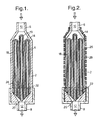
- Fig. 1 is a view in cross-section of the filtering device according to a first embodiment of the invention, wherein the filtered liquid is collected in the tubular housing;
- Fig. 2 is a view in cross-section of the filtering device according to a second embodiment of the invention;
- Fig. 3 is a cross-sectional view of the filtering device of Fig. 2 providing a further compartment for collecting the filtered liquid;
- Fig. 4 is a cross-sectional view of another embodiment of the filtering device according to the invention, providing bypass means for removing and collecting filtered liquid in a further compartment; and
- Fig. 5 is a view in partial cross-section of still a further embodiment of the invention.
- With specific reference now to the figures in detail, it is stressed that the particulars shown are by way of example and for purposes of illustrative discussion of the preferred embodiments of the present invention only and are presented in the cause of providing what is believed to be the most useful and readily understood description of the principles and conceptual aspects of the invention. In this regard, no attempt is made to show structural details of the invention in more detail than is necessary for a fundamental understanding of the invention, the description taken with the drawings making apparent to those skilled in the art how the several forms of the invention may be embodied in practice.
- There is shown in Fig. 1 a cross-sectional view of the fluid filtering device for separating liquid and solid particles from gases to be analyzed or monitored, which device includes a
tubular housing 2 of a relatively small diameter, defining aspace 4 therein and having aninlet end portion 6 and anoutlet end portion 8 defining thereinfluid flow passages end portions outlet end portions gradual transition sections internal space 4 of thehousing 2 and theinternal passageways end portions - Inside the
housing 2 is disposed afluid filter element 18, composed of a hydrophobic hollow fiber filter. Thefilter element 18 is preferably formed by folding over the fibers, thus providing a first closedend portion 19 and a secondopen end portion 20. Thefilter element 18 is shaped and located inside thehousing 2 such that the first closedend portion 19 reaches the space delimited by thetransition section 14 and the secondopen end portion 20 reaches the space delimited by thetransition section 16. Advantageously the internal diameters of thehousing 2 and theend sections filter element 18 and thepassageways filter element 18, in conjunction with the small diametertubular housing 2, form a filtering device having at least four times smaller volume per square centimeter of filter material or of effective filter area than the dead space obtained utilizing a filter element of the flat membrane type. In order to assure that non-filtered fluid will not reach theoutlet end portion 8, blockingmaterial 22 is inserted in between the hollow fibers and the inner surface of the wall of thehousing 2 at thesecond end portion 20. The filtering device may include means 24 for further reducing the dead space within thehousing 2. Such means may be embodied by non-permeable material, e.g., glass particles or beads, as illustrated in Fig. 1. - The closed
end portion 19 of thefilter element 18, as well as the walls along the entire fibers, provide thin walls through which the gas of the fluid to be filtered traverses with minimal disturbance. Hence, in the overall effort to provide an efficient fluid filter through which fluid can pass from the inlet to the outlet with minimal pressure applied thereto and with minimal disturbance, there is provided a combination of elements cooperating in achieving same. The elements include: - a) the
first transition section 14 preventing an abrupt transition of fluid flow from theinlet portion 10 to thespace 4 inside the housing, partially occupied by the filter; - b) a filter composed of hollow fibers closed at one end and open at the other, so as to cause the incoming fluid to pass only a thin wall prior to reaching the passageways inside the fibers, which passageways smoothly guide the filtered fluid from the inlet portion to the outlet portion, and
- c) the filtered fluid exiting the filter reaches a
second transition section 16 before arriving at theoutlet end portion 12. - In order to improve smooth and undisturbed fluid flow even further, the outlet portion of the filter through which filtered fluid gradually exits the fibers, i.e., the fibers at the outlet portion, is shaped so that the edges of the fibers do not terminate at one plane, but rather terminate at different cross-sectional planes, thereby causing the filtered fluid to exit the fibers across several planes when leaving the passageways and entering the transition section. Thus, during the entire filtering process, the fluid to be filtered is very carefully treated to avoid the mixing of the gas constituents while being flown into the monitor and similar disturbances in flow, which mixing of gases greatly increases the response time of the system to which the filtering device is connected. In other words, the structure of the filter, according to the present invention, effects the filtering of the fluid while preserving as much as possible the continuity of the patient's breath, as exhaled.
- It has been found that for a monitor sampling at flow rates lower than 50 ml/min, the average diameter of the
tubular housing 2 should be less than 2.5 mm, if nomeans 24 are included. For higher flow rates, however, the average diameter of thetubular housing 2 can be increased accordingly, for example, for flow rates of approximately 150 ml/min, a diameter of up to 3.5 mm could be used. - The liquid collected during use of the device will gradually immerse portions of the
filter element 18, rendering those parts inactive. Eventually, when at least the major portion of the filter element is submerged, the filtering device becomes ineffective, and is replaced. - In order to prolong the effective usable life time of the filter device according to a further embodiment of the present invention illustrated in Fig. 2, the
tubular housing 26, or a portion thereof, is made of suitable liquid permeable material allowing the traversing of humidity, moisture and liquids, but preventing the traversing of gases. An example of such material is Nafion. Hence, the filtered out liquid, or at least some of it, is continuously removed from the device through the wall of thehousing 26. In order to protect the Nafion-made housing wall against bending, which is detrimental to smooth fluid flow, the wall is covered with abraided sleeve 28, for example, a plastic sleeve. Such a sleeve allows continuous ventilation of the Nafion wall, while guarding same against bending and damage. - Referring to Fig. 3, there is shown an embodiment of the filtering device of the type furnished with a
housing 26 made of a material allowing the traversing of humidity and moisture, as described above. Thehousing 26 is enclosed by ajacket 30 defining thereinbetween a liquid retaining space. Advantageously thejacket 30 encapsulatesliquid absorbing material 32, such as silica gel. Thismaterial 32 is used to absorb the fluid transferred through the wall of thehousing 26 from within thespace 4 to the outside. In this manner, the wall is kept dry, thereby enhancing the liquid transfer capabilities of the housing wall. - In cases where a substantial amount of filtered out liquid is to be removed, further means for more positive removal of filtered out liquid can be provided, as illustrated in Fig. 4. Such means include a
nozzle 34 connectable to a vacuum pump applying a suction action to the interior of theenvelope 30. At the entrance to thenozzle 34, there may be introduced ahydrophobic filter 36 preventing liquid from reaching the pump. In the wall ofhousing 38 there are formedopenings 40, through which openings accumulated liquid can pass. - The embodiment illustrated in Fig. 5 is adapted to be utilized with a patient's ventilation system, incorporating a T-
piece 42. Oneopening 44 of the T-piece 42 leads to a patient's mouth, while theopposite opening 46 leads to a ventilation system. To thethird opening 48 there is coupled a hollowfiber filter element 18. Theelement 18 is mounted in aunit 50, having afirst portion 52, configured to be inserted and retained in theopening 48 of the T-piece 42, and anozzle portion 54, which is in fluid communication through thefilter 18 with the T-piece 42. Atube 56 having astandard connecting socket 58 at one end and leading to a gas analyzer or monitor can be easily attached to thenozzle portion 54. Theentire unit 50 is thus disengageable and replaceable. - As further seen in the figure, since the airway of the T-
piece 42 is rather large, there is obtained a relatively large filtering area. Thesample tube 56 sucks only clean gas, hence a gas analyzer or monitor connected thereto has to deal only with condensed humidity gas, whereas human excretions (saliva, blood or other liquids), are prevented from entering thetube 56. - Furthermore, since the hollow fibers with their very thin membrane walls provide minimum resistance, permitting the fast flow of gas along the T-
piece 42 to pass freely through them, the effect of this configuration on the response time of the analyzer or monitor is negligible even when a large bundle of fibers is used in theelement 18. It should also be mentioned that this type of configuration has the advantage that thehydrophobic filter element 18 prevents the sample tube from becoming blocked or filled with patient's excretions, commonly found in the airways, which is often the case with devices of other configurations, without impairing the response time of the device. - It will be evident to those skilled in the art that the invention is not limited to the details of the foregoing illustrated embodiments and that the present invention may be embodied in other specific forms without departing from the spirit or essential attributes thereof. The present embodiments are therefore to be considered in all respects as illustrative and not restrictive, the scope of the invention being indicated by the appended claims rather than by the foregoing description, and all changes which come within the meaning and range of equivalency of the claims are therefore intended to be embraced therein.
Claims (19)
- A fluid filtering device for separating liquid from gases to be analyzed, comprising:a tubular housing defining a space therein and having inlet and outlet end portions delimiting passageways in fluid communication with said space, said portions being configured to be connectable between a source of fluid and a gas analyzer, anda liquid/gas hydrophobic hollow fiber filter element located within said tubular housing preventing material other than gases to pass therethrough,said tubular housing and filter element forming a small volume within said housing, and said device being effectively operable independent of its orientation, or field of gravitation acting thereon.
- The device as claimed in claim 1, wherein at least one of said end portions is provided with a transition section in which the internal fluid flow path leading from said space in the housing to said passageway is gradually restricted.
- The device as claimed in claim 3, wherein said tubular housing and end portions are cylindrical and the cross-sectional area of at least one of said passageways is similar to the cross-sectional area of said space unoccupied by the cross-sectional area of said filter element disposed therein.
- The device as claimed in claim 1, wherein one end portion of said filter element reaches the space delimited by said transition section.
- The device as claimed in claim 1, further comprising means for trapping filtered out liquid.
- The device as claimed in claim 5, wherein said means for trapping filtered out liquid is constituted by at least a portion of said tubular housing provided with liquid vapour permeable material.
- The device as claimed in claim 5, wherein said means for trapping filtered out liquid comprises at least one opening in a wall of said tubular housing.
- The device as claimed in claim 5, further comprising an outer jacket enclosing at least a portion of said housing and defining liquid collecting space between the outer walls of said housing and the inner wall of said jacket.
- The device as claimed in claim 8, wherein said liquid collecting space comprises liquid absorbing material.
- The device as claimed in claim 8, wherein said jacket is provided with means connectable to a vacuum pump for applying a suction action to said collecting space.
- The device as claimed in claim 10, further comprising a hydrophobic filter for preventing liquid from reaching said vacuum pump.
- The device as claimed in claim 1, wherein the hollow fibers of said filter element are folded over to form a closed end portion disposed adjacent said inlet portion.
- The device as claimed in claim 12, further comprising flow blocking means for preventing unfiltered fluid from reaching said outlet end portion.
- The device as claimed in claim 12, wherein for a flow rate lower than 50 ml/min said tubular housing has a diameter of less than 2.5. mm.
- The device as claimed in claim 12, wherein for a flow rate of substantially 150 ml/min said tubular housing has a diameter of less than 3.5 mm.
- The fluid filtering device as claimed in claim 1, wherein said tubular housing is substantially T-shaped and has three openings, a first opening leading to a patient's mouth, a second opposite opening leading to a ventilation system and a third opening leading to a gas analyzer, and said filter element is affixed in the opening leading to a gas analyzer.
- The fluid filtering device as claimed in claim 16, wherein said hollow fibers have first and a second end portions, said first end portion being affixed in the opening leading to a gas analyzer and said second end portion traverses a line connecting said first and second openings to the extent that it will allow substantially undisturbed ventilation to a patient.
- The fluid filtering device as claimed in claim 16, wherein said filter element is mounted in a unit having a first portion configured for insertion into said third opening and a nozzle portion, in fluid communication with said first portion to which there is connectable a tube leading to a gas analyzer.
- The fluid filter device as claimed in claim 16, wherein said base is disengageable for replacement.
Applications Claiming Priority (2)
| Application Number | Priority Date | Filing Date | Title |
|---|---|---|---|
| IL11116294 | 1994-10-04 | ||
| IL111162A IL111162A (en) | 1994-10-04 | 1994-10-04 | Filtering device utilizable with gas monitors |
Publications (2)
| Publication Number | Publication Date |
|---|---|
| EP0707827A1 true EP0707827A1 (en) | 1996-04-24 |
| EP0707827B1 EP0707827B1 (en) | 2003-01-15 |
Family
ID=11066605
Family Applications (1)
| Application Number | Title | Priority Date | Filing Date |
|---|---|---|---|
| EP95307005A Expired - Lifetime EP0707827B1 (en) | 1994-10-04 | 1995-10-03 | Fluid filtering device utilizable with gas monitors |
Country Status (7)
| Country | Link |
|---|---|
| US (1) | US5657750A (en) |
| EP (1) | EP0707827B1 (en) |
| JP (2) | JP3727698B2 (en) |
| AT (1) | ATE230953T1 (en) |
| CA (1) | CA2159769A1 (en) |
| DE (1) | DE69529385T2 (en) |
| IL (1) | IL111162A (en) |
Cited By (8)
| Publication number | Priority date | Publication date | Assignee | Title |
|---|---|---|---|---|
| GB2322568A (en) * | 1997-02-28 | 1998-09-02 | Smiths Industries Plc | Gas treatment device containing an asymmetric gas flow deflector element |
| WO2004023998A1 (en) * | 2002-09-16 | 2004-03-25 | Aerocrine Ab | Scrubber |
| CN100335006C (en) * | 2002-09-16 | 2007-09-05 | 艾罗克林有限公司 | Scrubber |
| EP2363065A1 (en) * | 2010-01-28 | 2011-09-07 | Nihon Kohden Corporation | Gas analyzer |
| CN102553366A (en) * | 2010-12-17 | 2012-07-11 | 江苏江分电分析仪器有限公司 | Gas purifying device |
| WO2013046098A3 (en) * | 2011-09-29 | 2013-07-04 | Koninklijke Philips Electronics N.V. | Pressure sensing tube with in-line contaminant blocking |
| WO2014027290A1 (en) * | 2012-08-15 | 2014-02-20 | Koninklijke Philips N.V. | Sidestream respiratory gas sampling system with flexible accessories and removable water trap |
| WO2015094439A1 (en) * | 2013-12-20 | 2015-06-25 | General Electric Company | Liquid separator for removing a liquid from a sample of a breathing gas and airway adapter |
Families Citing this family (61)
| Publication number | Priority date | Publication date | Assignee | Title |
|---|---|---|---|---|
| IT1272858B (en) * | 1995-01-03 | 1997-07-01 | Dar Spa | DISPOSABLE ACTIVE HUMIDIFIER PARTICULARLY FOR INSPIRATORY LINES OF RESPIRATORY CIRCUITS FOR INTENSIVE THERAPY |
| DE19621541C1 (en) * | 1996-05-29 | 1997-04-10 | Draegerwerk Ag | Respirator machine humidifier with hollow fibre membrane |
| US5826575A (en) * | 1997-03-13 | 1998-10-27 | Nellcor Puritan Bennett, Incorporated | Exhalation condensate collection system for a patient ventilator |
| US6165244A (en) * | 1999-03-13 | 2000-12-26 | Aaf International, Inc. | Filter media with fluid stream positioned fibers |
| US6656127B1 (en) | 1999-06-08 | 2003-12-02 | Oridion Breathid Ltd. | Breath test apparatus and methods |
| JP2003524149A (en) * | 1999-06-08 | 2003-08-12 | オリディオン ブレシド リミティド | Gas analyzer verification test equipment |
| US6387144B1 (en) * | 2000-03-16 | 2002-05-14 | Nelson Industries, Inc. | Enhanced performance fibrous filter media and extended life fluid filter assembly |
| WO2002079739A1 (en) * | 2001-03-28 | 2002-10-10 | Perkinelmer, Inc. | Concentration detection system |
| US20030024528A1 (en) * | 2001-08-04 | 2003-02-06 | Graham James E. | Moisture trap |
| ES2262872T3 (en) * | 2001-12-06 | 2006-12-01 | Cardinal Health 303, Inc. | DRUG INFUSION SYSTEM BY CO2 MONITORING. |
| IL148468A (en) | 2002-03-03 | 2012-12-31 | Exalenz Bioscience Ltd | Breath collection system |
| US7549316B2 (en) * | 2002-10-08 | 2009-06-23 | Ric Investments, Llc. | Integrated sample cell and filter and system using same |
| US7121134B2 (en) * | 2002-10-08 | 2006-10-17 | Ric Investments, Llc. | Integrated sample cell and filter and system using same |
| US7294839B2 (en) * | 2002-10-08 | 2007-11-13 | Ric Investements, Inc. | Low volume sample cell and gas monitoring system using same |
| US7059322B2 (en) * | 2002-10-11 | 2006-06-13 | Ric Investments, Llc. | Low deadspace airway adapter |
| US20040094149A1 (en) * | 2002-11-14 | 2004-05-20 | Creative Biomedics, Inc. | Pulmonary function filter, pulmonary sensor combination and components thereof |
| US20040236242A1 (en) * | 2003-05-22 | 2004-11-25 | Graham James E. | Capnograph system with integral controller |
| US6878938B2 (en) * | 2003-07-16 | 2005-04-12 | Perkinelmer, Inc. | High frequency infrared radiation source |
| FR2858236B1 (en) | 2003-07-29 | 2006-04-28 | Airox | DEVICE AND METHOD FOR SUPPLYING RESPIRATORY GAS IN PRESSURE OR VOLUME |
| US20050042133A1 (en) * | 2003-08-22 | 2005-02-24 | Rosemount Analytical Inc. | Chemical analyzer probe with chemical selective filter |
| US7353689B2 (en) * | 2004-02-17 | 2008-04-08 | Ge Healthcare Finland Oy | Liquid separator for a gas analyzer and method for separating a liquid component from gas |
| US20050217226A1 (en) * | 2004-04-05 | 2005-10-06 | 3M Innovative Properties Company | Pleated aligned web filter |
| JP2006095465A (en) * | 2004-09-30 | 2006-04-13 | Nok Corp | Purifying apparatus |
| US8028697B2 (en) | 2005-04-28 | 2011-10-04 | Trudell Medical International | Ventilator circuit and method for the use thereof |
| EP1885460B1 (en) | 2005-05-10 | 2019-11-06 | Oridion Medical, Ltd. | Fluid drying mechanism |
| US8240187B2 (en) | 2005-08-16 | 2012-08-14 | Oridion Medical (1987) Ltd. | Breath sampling device and method for using same |
| JP4932724B2 (en) * | 2005-09-02 | 2012-05-16 | エーザイ・アール・アンド・ディー・マネジメント株式会社 | Screening method of substances useful for diseases using GPR120 and phospholipase |
| EP2265309B1 (en) | 2008-03-17 | 2015-12-16 | Discovery Laboratories, Inc. | Ventilation circuit adaptor and proximal aerosol delivery system |
| US8457706B2 (en) | 2008-05-16 | 2013-06-04 | Covidien Lp | Estimation of a physiological parameter using a neural network |
| US8302602B2 (en) | 2008-09-30 | 2012-11-06 | Nellcor Puritan Bennett Llc | Breathing assistance system with multiple pressure sensors |
| ES2402241T3 (en) | 2008-10-22 | 2013-04-30 | Trudell Medical International | Modular Spray Supply System |
| US8434479B2 (en) | 2009-02-27 | 2013-05-07 | Covidien Lp | Flow rate compensation for transient thermal response of hot-wire anemometers |
| CN101569511B (en) * | 2009-05-20 | 2011-01-05 | 曹孟君 | Beauty and health care bathtub |
| US8776787B2 (en) * | 2009-08-20 | 2014-07-15 | Eddie Dewayne JENKINS | Adaptor and breathing assist device using the same |
| US8469030B2 (en) | 2009-12-01 | 2013-06-25 | Covidien Lp | Exhalation valve assembly with selectable contagious/non-contagious latch |
| US8439037B2 (en) | 2009-12-01 | 2013-05-14 | Covidien Lp | Exhalation valve assembly with integrated filter and flow sensor |
| US8439036B2 (en) | 2009-12-01 | 2013-05-14 | Covidien Lp | Exhalation valve assembly with integral flow sensor |
| US8469031B2 (en) | 2009-12-01 | 2013-06-25 | Covidien Lp | Exhalation valve assembly with integrated filter |
| USD655809S1 (en) | 2010-04-27 | 2012-03-13 | Nellcor Puritan Bennett Llc | Valve body with integral flow meter for an exhalation module |
| USD655405S1 (en) | 2010-04-27 | 2012-03-06 | Nellcor Puritan Bennett Llc | Filter and valve body for an exhalation module |
| USD653749S1 (en) | 2010-04-27 | 2012-02-07 | Nellcor Puritan Bennett Llc | Exhalation module filter body |
| US9629971B2 (en) | 2011-04-29 | 2017-04-25 | Covidien Lp | Methods and systems for exhalation control and trajectory optimization |
| US9364624B2 (en) | 2011-12-07 | 2016-06-14 | Covidien Lp | Methods and systems for adaptive base flow |
| US9498589B2 (en) | 2011-12-31 | 2016-11-22 | Covidien Lp | Methods and systems for adaptive base flow and leak compensation |
| US9144658B2 (en) | 2012-04-30 | 2015-09-29 | Covidien Lp | Minimizing imposed expiratory resistance of mechanical ventilator by optimizing exhalation valve control |
| USD731049S1 (en) | 2013-03-05 | 2015-06-02 | Covidien Lp | EVQ housing of an exhalation module |
| USD731048S1 (en) | 2013-03-08 | 2015-06-02 | Covidien Lp | EVQ diaphragm of an exhalation module |
| USD744095S1 (en) | 2013-03-08 | 2015-11-24 | Covidien Lp | Exhalation module EVQ internal flow sensor |
| USD692556S1 (en) | 2013-03-08 | 2013-10-29 | Covidien Lp | Expiratory filter body of an exhalation module |
| USD701601S1 (en) | 2013-03-08 | 2014-03-25 | Covidien Lp | Condensate vial of an exhalation module |
| USD731065S1 (en) | 2013-03-08 | 2015-06-02 | Covidien Lp | EVQ pressure sensor filter of an exhalation module |
| USD736905S1 (en) | 2013-03-08 | 2015-08-18 | Covidien Lp | Exhalation module EVQ housing |
| USD693001S1 (en) | 2013-03-08 | 2013-11-05 | Covidien Lp | Neonate expiratory filter assembly of an exhalation module |
| US9950135B2 (en) | 2013-03-15 | 2018-04-24 | Covidien Lp | Maintaining an exhalation valve sensor assembly |
| US10010690B1 (en) | 2013-03-15 | 2018-07-03 | Monitoring For Life, Llc | Endotracheal tube apparatus |
| US10112024B2 (en) | 2014-01-17 | 2018-10-30 | Monitoring For Life Llc | Medical tube apparatus |
| US10315148B2 (en) * | 2014-11-03 | 2019-06-11 | Esa European Space Agency | Fluidic filter |
| USD775345S1 (en) | 2015-04-10 | 2016-12-27 | Covidien Lp | Ventilator console |
| EP3713657A4 (en) * | 2017-12-21 | 2021-09-01 | Oridion Medical 1987 Ltd. | Bypass filter |
| US11612846B2 (en) | 2018-03-12 | 2023-03-28 | Westmed, Inc. | Low dead space laminar flow water filter for side stream CO2 monitoring lines |
| US11896767B2 (en) | 2020-03-20 | 2024-02-13 | Covidien Lp | Model-driven system integration in medical ventilators |
Citations (5)
| Publication number | Priority date | Publication date | Assignee | Title |
|---|---|---|---|---|
| US4456014A (en) * | 1983-01-03 | 1984-06-26 | Thoratec Laboratories Corporation | Flow restrictor |
| EP0275105A2 (en) * | 1987-01-16 | 1988-07-20 | SpaceLabs Medical, Inc. | Airway adapter |
| US4985055A (en) * | 1988-12-19 | 1991-01-15 | The Boc Group, Inc. | Liquid/gas separation device |
| WO1991001771A1 (en) * | 1989-08-04 | 1991-02-21 | Nellcor Incorporated | Improved airway adapter with purge means |
| EP0549266A2 (en) * | 1991-12-20 | 1993-06-30 | Instrumentarium Corporation | Apparatus for separating a liquid component from exhalation air to be delivered to an analyzing unit |
Family Cites Families (38)
| Publication number | Priority date | Publication date | Assignee | Title |
|---|---|---|---|---|
| US3422008A (en) * | 1963-10-24 | 1969-01-14 | Dow Chemical Co | Wound hollow fiber permeability apparatus and process of making the same |
| US3803810A (en) * | 1972-05-01 | 1974-04-16 | Pall Corp | Liquid-gas separator and filter |
| JPS5949018B2 (en) * | 1976-10-15 | 1984-11-30 | 旭化成株式会社 | drug syringe |
| JPS551816A (en) * | 1978-06-15 | 1980-01-09 | Mitsubishi Rayon Co Ltd | Vapor-liquid contactor |
| US4327718A (en) * | 1980-09-18 | 1982-05-04 | Becton, Dickinson And Company | Continuously draining trap for removal of condensate from a patient breathing circuit |
| US4612019A (en) * | 1982-07-22 | 1986-09-16 | The Dow Chemical Company | Method and device for separating water vapor from air |
| US4568366A (en) * | 1983-08-30 | 1986-02-04 | Baxter Laboratories, Inc. | In-line filter |
| US4579568A (en) * | 1983-10-11 | 1986-04-01 | Biochem International Inc. | Gas analyzer separator |
| US4558708A (en) * | 1984-10-24 | 1985-12-17 | Tri-Med, Inc. | Patient's airway adapter to withdraw a patient's gas samples for testing free of sputum mucus and/or condensed water, by utilizing a hollow cylindrical hydrophobic liquid baffle |
| IL76939A (en) * | 1984-11-13 | 1990-01-18 | Andros Analyzers Inc | Adaptor assembly for airway tube |
| JPS61144324A (en) * | 1984-12-19 | 1986-07-02 | Idemitsu Petrochem Co Ltd | Extruding method of thermoplastic resin and extruding device therefor |
| DE3650465T2 (en) * | 1985-02-09 | 1996-09-12 | Asahi Chemical Ind | Permeable polymer membrane for gas drying |
| US4615694A (en) * | 1985-02-15 | 1986-10-07 | Burron Medical Inc. | Vented cone filter |
| US4678488A (en) * | 1985-05-02 | 1987-07-07 | Sensors, Inc. | Liquid separator for gas analyzer |
| US4668401A (en) * | 1985-06-19 | 1987-05-26 | Mitsubishi Rayon Co., Ltd. | Hollow-fiber filter module and filtration method using the same |
| US4824444A (en) * | 1986-04-11 | 1989-04-25 | Applied Membrane Technology, Inc. | Gas permselective composite membrane prepared by plasma polymerization coating techniques |
| US5064418A (en) * | 1986-05-06 | 1991-11-12 | Microgon, Inc. | Filter means for use with syringe and needle |
| US4713095A (en) * | 1986-10-16 | 1987-12-15 | Criticare Systems, Inc. | Liquid separator for gas analyzer |
| FI76488C (en) * | 1987-05-05 | 1988-11-10 | Instrumentarium Oy | ROERVATTENAVSKILJARE TILL EN GASANALYSATOR. |
| JPH02501391A (en) * | 1987-09-10 | 1990-05-17 | ヒューレット・パッカード・カンパニー | water vapor permeable material |
| FI80203C (en) * | 1988-01-11 | 1990-05-10 | Instrumentarium Oy | Method for sealing the water separator membrane in a gas analyzer |
| US4924860A (en) * | 1988-08-26 | 1990-05-15 | Criticare Systems, Inc. | Water trap and associated control system |
| US4929259A (en) * | 1989-02-09 | 1990-05-29 | The Dow Chemical Company | Hollow fiber membrane fluid separation module for boreside feed |
| GB8916361D0 (en) * | 1989-07-18 | 1989-09-06 | Smiths Industries Plc | Filters |
| US5101817A (en) * | 1989-08-04 | 1992-04-07 | Nellcor, Inc. | Airway adapter for use with closed suction catheter system |
| US5002590A (en) * | 1989-09-19 | 1991-03-26 | Bend Research, Inc. | Countercurrent dehydration by hollow fibers |
| US5067971A (en) * | 1990-02-12 | 1991-11-26 | Union Carbide Industrial Gases Technology Corporation | Process for dehydration of gases and composite permeable membranes therefor |
| US5026479A (en) * | 1990-02-13 | 1991-06-25 | Union Carbide Industrial Gases Technology Corporation | Fluid separation device |
| US5131387A (en) * | 1990-05-09 | 1992-07-21 | Marquette Gas Analysis Corp. | Moisture trap |
| US5049170A (en) * | 1990-09-11 | 1991-09-17 | Andros Incorporated | Filter assembly for gas analyzer |
| US5071552A (en) * | 1990-12-20 | 1991-12-10 | Union Carbide Industrial Gases Technology Corporation | Multiple bundle fluid separation apparatus |
| AU647856B2 (en) * | 1990-12-28 | 1994-03-31 | Terumo Kabushiki Kaisha | Transfusion filtering device |
| US5158581A (en) * | 1991-07-29 | 1992-10-27 | Coplan Myron J | Fluid separation membrane module with hollow fibers having segregated active surface regions |
| US5160042A (en) * | 1991-11-05 | 1992-11-03 | Praxair Technology, Inc. | Double ended hollow fiber bundle and fluids separation apparatus |
| US5293875A (en) * | 1992-06-16 | 1994-03-15 | Natus Medical Incorporated | In-vivo measurement of end-tidal carbon monoxide concentration apparatus and methods |
| US5282964A (en) * | 1993-02-19 | 1994-02-01 | The Dow Chemical Company | Boreside feed hollow fiber membrane device |
| US5380433A (en) * | 1993-06-01 | 1995-01-10 | E. I. Du Pont De Nemours And Company | Hollow fiber membrane separation device with a housing made from a flexible material |
| US5398677A (en) * | 1993-07-27 | 1995-03-21 | Smith; Charles A. | Condensation collector for respiration system |
-
1994
- 1994-10-04 IL IL111162A patent/IL111162A/en not_active IP Right Cessation
-
1995
- 1995-09-29 US US08/535,345 patent/US5657750A/en not_active Expired - Lifetime
- 1995-10-03 EP EP95307005A patent/EP0707827B1/en not_active Expired - Lifetime
- 1995-10-03 DE DE69529385T patent/DE69529385T2/en not_active Expired - Lifetime
- 1995-10-03 JP JP27827195A patent/JP3727698B2/en not_active Expired - Lifetime
- 1995-10-03 AT AT95307005T patent/ATE230953T1/en not_active IP Right Cessation
- 1995-10-03 CA CA002159769A patent/CA2159769A1/en not_active Abandoned
-
2005
- 2005-06-27 JP JP2005187174A patent/JP2005300554A/en active Pending
Patent Citations (5)
| Publication number | Priority date | Publication date | Assignee | Title |
|---|---|---|---|---|
| US4456014A (en) * | 1983-01-03 | 1984-06-26 | Thoratec Laboratories Corporation | Flow restrictor |
| EP0275105A2 (en) * | 1987-01-16 | 1988-07-20 | SpaceLabs Medical, Inc. | Airway adapter |
| US4985055A (en) * | 1988-12-19 | 1991-01-15 | The Boc Group, Inc. | Liquid/gas separation device |
| WO1991001771A1 (en) * | 1989-08-04 | 1991-02-21 | Nellcor Incorporated | Improved airway adapter with purge means |
| EP0549266A2 (en) * | 1991-12-20 | 1993-06-30 | Instrumentarium Corporation | Apparatus for separating a liquid component from exhalation air to be delivered to an analyzing unit |
Cited By (18)
| Publication number | Priority date | Publication date | Assignee | Title |
|---|---|---|---|---|
| GB2322568A (en) * | 1997-02-28 | 1998-09-02 | Smiths Industries Plc | Gas treatment device containing an asymmetric gas flow deflector element |
| US6017374A (en) * | 1997-02-28 | 2000-01-25 | Smiths Industries Public Limited Company | Gas treatment devices |
| GB2322568B (en) * | 1997-02-28 | 2000-09-27 | Smiths Industries Plc | Gas treatment devices |
| WO2004023998A1 (en) * | 2002-09-16 | 2004-03-25 | Aerocrine Ab | Scrubber |
| AU2003253542B2 (en) * | 2002-09-16 | 2007-07-26 | Aerocrine Ab | Scrubber |
| CN100335006C (en) * | 2002-09-16 | 2007-09-05 | 艾罗克林有限公司 | Scrubber |
| US9417222B2 (en) | 2010-01-28 | 2016-08-16 | Nihon Kohden Corporation | Gas analyzer |
| US8823533B2 (en) | 2010-01-28 | 2014-09-02 | Nihon Kohden Corporation | Gas analyzer |
| EP2363065A1 (en) * | 2010-01-28 | 2011-09-07 | Nihon Kohden Corporation | Gas analyzer |
| CN102553366A (en) * | 2010-12-17 | 2012-07-11 | 江苏江分电分析仪器有限公司 | Gas purifying device |
| WO2013046098A3 (en) * | 2011-09-29 | 2013-07-04 | Koninklijke Philips Electronics N.V. | Pressure sensing tube with in-line contaminant blocking |
| WO2014027290A1 (en) * | 2012-08-15 | 2014-02-20 | Koninklijke Philips N.V. | Sidestream respiratory gas sampling system with flexible accessories and removable water trap |
| US9974916B2 (en) | 2012-08-15 | 2018-05-22 | Koninklijke Philips N.V. | Sidestream respiratory gas sampling system with flexible accessories and removable water trap |
| WO2015094439A1 (en) * | 2013-12-20 | 2015-06-25 | General Electric Company | Liquid separator for removing a liquid from a sample of a breathing gas and airway adapter |
| US9572948B2 (en) | 2013-12-20 | 2017-02-21 | General Electric Company | Liquid separator for removing a liquid from a sample of a breathing gas and airway adapter |
| CN106659431A (en) * | 2013-12-20 | 2017-05-10 | 通用电气公司 | Liquid separator for removing a liquid from a sample of a breathing gas and airway adapter |
| CN106659431B (en) * | 2013-12-20 | 2020-03-17 | 通用电气公司 | Liquid separator for removing liquid from a respiratory gas sample and airway adapter |
| EP3682800A1 (en) * | 2013-12-20 | 2020-07-22 | General Electric Company | Liquid separator for removing a liquid from a sample of a breathing gas and airway adapter |
Also Published As
| Publication number | Publication date |
|---|---|
| JP2005300554A (en) | 2005-10-27 |
| JP3727698B2 (en) | 2005-12-14 |
| ATE230953T1 (en) | 2003-02-15 |
| EP0707827B1 (en) | 2003-01-15 |
| DE69529385D1 (en) | 2003-02-20 |
| IL111162A0 (en) | 1994-12-29 |
| DE69529385T2 (en) | 2003-10-09 |
| IL111162A (en) | 1998-01-04 |
| JPH08299764A (en) | 1996-11-19 |
| US5657750A (en) | 1997-08-19 |
| CA2159769A1 (en) | 1996-04-05 |
Similar Documents
| Publication | Publication Date | Title |
|---|---|---|
| US5657750A (en) | Fluid filtering device utilizable with gas monitors | |
| EP1924854B1 (en) | Breath sampling device and method for using same | |
| US4985055A (en) | Liquid/gas separation device | |
| JP5208935B2 (en) | Modular sidestream gas sampling assembly | |
| US5042500A (en) | Drying sample line | |
| US5857461A (en) | Multiple channel sample port | |
| US8252080B2 (en) | Liquid absorbing filter assembly and system using same | |
| US5365938A (en) | Apparatus for separating a liquid component from exhalation air to be delivered to an analyzing unit | |
| US20180146886A1 (en) | Handpiece for Respiratory Monitor | |
| JP2013068630A (en) | Integrated sample cell and filter, and system using them | |
| JP4613067B2 (en) | Integrated specimen cell-filter and apparatus using the same | |
| JPS62501127A (en) | Airway tube adapter assembly | |
| JPS63173985A (en) | Radioactive iodine monitor | |
| JPH08101096A (en) | Expiration sampler |
Legal Events
| Date | Code | Title | Description |
|---|---|---|---|
| PUAI | Public reference made under article 153(3) epc to a published international application that has entered the european phase |
Free format text: ORIGINAL CODE: 0009012 |
|
| AK | Designated contracting states |
Kind code of ref document: A1 Designated state(s): AT BE CH DE DK ES FR GB GR IE IT LI LU MC NL PT SE |
|
| 17P | Request for examination filed |
Effective date: 19960918 |
|
| RAP1 | Party data changed (applicant data changed or rights of an application transferred) |
Owner name: ORIDION MEDICAL LTD. |
|
| 17Q | First examination report despatched |
Effective date: 20000327 |
|
| GRAG | Despatch of communication of intention to grant |
Free format text: ORIGINAL CODE: EPIDOS AGRA |
|
| GRAG | Despatch of communication of intention to grant |
Free format text: ORIGINAL CODE: EPIDOS AGRA |
|
| GRAG | Despatch of communication of intention to grant |
Free format text: ORIGINAL CODE: EPIDOS AGRA |
|
| GRAH | Despatch of communication of intention to grant a patent |
Free format text: ORIGINAL CODE: EPIDOS IGRA |
|
| GRAH | Despatch of communication of intention to grant a patent |
Free format text: ORIGINAL CODE: EPIDOS IGRA |
|
| GRAA | (expected) grant |
Free format text: ORIGINAL CODE: 0009210 |
|
| AK | Designated contracting states |
Kind code of ref document: B1 Designated state(s): AT BE CH DE DK ES FR GB GR IE IT LI LU MC NL PT SE |
|
| PG25 | Lapsed in a contracting state [announced via postgrant information from national office to epo] |
Ref country code: NL Free format text: LAPSE BECAUSE OF FAILURE TO SUBMIT A TRANSLATION OF THE DESCRIPTION OR TO PAY THE FEE WITHIN THE PRESCRIBED TIME-LIMIT Effective date: 20030115 Ref country code: LI Free format text: LAPSE BECAUSE OF FAILURE TO SUBMIT A TRANSLATION OF THE DESCRIPTION OR TO PAY THE FEE WITHIN THE PRESCRIBED TIME-LIMIT Effective date: 20030115 Ref country code: GR Free format text: LAPSE BECAUSE OF FAILURE TO SUBMIT A TRANSLATION OF THE DESCRIPTION OR TO PAY THE FEE WITHIN THE PRESCRIBED TIME-LIMIT Effective date: 20030115 Ref country code: FR Free format text: LAPSE BECAUSE OF NON-PAYMENT OF DUE FEES Effective date: 20030115 Ref country code: CH Free format text: LAPSE BECAUSE OF FAILURE TO SUBMIT A TRANSLATION OF THE DESCRIPTION OR TO PAY THE FEE WITHIN THE PRESCRIBED TIME-LIMIT Effective date: 20030115 Ref country code: BE Free format text: LAPSE BECAUSE OF FAILURE TO SUBMIT A TRANSLATION OF THE DESCRIPTION OR TO PAY THE FEE WITHIN THE PRESCRIBED TIME-LIMIT Effective date: 20030115 Ref country code: AT Free format text: LAPSE BECAUSE OF FAILURE TO SUBMIT A TRANSLATION OF THE DESCRIPTION OR TO PAY THE FEE WITHIN THE PRESCRIBED TIME-LIMIT Effective date: 20030115 |
|
| REG | Reference to a national code |
Ref country code: GB Ref legal event code: FG4D Ref country code: CH Ref legal event code: EP |
|
| REG | Reference to a national code |
Ref country code: IE Ref legal event code: FG4D |
|
| REF | Corresponds to: |
Ref document number: 69529385 Country of ref document: DE Date of ref document: 20030220 Kind code of ref document: P |
|
| PG25 | Lapsed in a contracting state [announced via postgrant information from national office to epo] |
Ref country code: SE Free format text: LAPSE BECAUSE OF FAILURE TO SUBMIT A TRANSLATION OF THE DESCRIPTION OR TO PAY THE FEE WITHIN THE PRESCRIBED TIME-LIMIT Effective date: 20030415 Ref country code: PT Free format text: LAPSE BECAUSE OF FAILURE TO SUBMIT A TRANSLATION OF THE DESCRIPTION OR TO PAY THE FEE WITHIN THE PRESCRIBED TIME-LIMIT Effective date: 20030415 Ref country code: DK Free format text: LAPSE BECAUSE OF FAILURE TO SUBMIT A TRANSLATION OF THE DESCRIPTION OR TO PAY THE FEE WITHIN THE PRESCRIBED TIME-LIMIT Effective date: 20030415 |
|
| NLV1 | Nl: lapsed or annulled due to failure to fulfill the requirements of art. 29p and 29m of the patents act | ||
| PG25 | Lapsed in a contracting state [announced via postgrant information from national office to epo] |
Ref country code: ES Free format text: LAPSE BECAUSE OF FAILURE TO SUBMIT A TRANSLATION OF THE DESCRIPTION OR TO PAY THE FEE WITHIN THE PRESCRIBED TIME-LIMIT Effective date: 20030730 |
|
| REG | Reference to a national code |
Ref country code: CH Ref legal event code: PL |
|
| PG25 | Lapsed in a contracting state [announced via postgrant information from national office to epo] |
Ref country code: LU Free format text: LAPSE BECAUSE OF NON-PAYMENT OF DUE FEES Effective date: 20031003 Ref country code: IE Free format text: LAPSE BECAUSE OF NON-PAYMENT OF DUE FEES Effective date: 20031003 |
|
| PG25 | Lapsed in a contracting state [announced via postgrant information from national office to epo] |
Ref country code: MC Free format text: LAPSE BECAUSE OF NON-PAYMENT OF DUE FEES Effective date: 20031031 |
|
| PLBE | No opposition filed within time limit |
Free format text: ORIGINAL CODE: 0009261 |
|
| STAA | Information on the status of an ep patent application or granted ep patent |
Free format text: STATUS: NO OPPOSITION FILED WITHIN TIME LIMIT |
|
| EN | Fr: translation not filed | ||
| 26N | No opposition filed |
Effective date: 20031016 |
|
| REG | Reference to a national code |
Ref country code: IE Ref legal event code: MM4A |
|
| PGFP | Annual fee paid to national office [announced via postgrant information from national office to epo] |
Ref country code: GB Payment date: 20140924 Year of fee payment: 20 |
|
| PGFP | Annual fee paid to national office [announced via postgrant information from national office to epo] |
Ref country code: DE Payment date: 20140924 Year of fee payment: 20 |
|
| PGFP | Annual fee paid to national office [announced via postgrant information from national office to epo] |
Ref country code: IT Payment date: 20140926 Year of fee payment: 20 |
|
| REG | Reference to a national code |
Ref country code: DE Ref legal event code: R071 Ref document number: 69529385 Country of ref document: DE |
|
| REG | Reference to a national code |
Ref country code: GB Ref legal event code: PE20 Expiry date: 20151002 |
|
| PG25 | Lapsed in a contracting state [announced via postgrant information from national office to epo] |
Ref country code: GB Free format text: LAPSE BECAUSE OF EXPIRATION OF PROTECTION Effective date: 20151002 |