EP0710904A1 - Backplane-Steuerung für Spinnereimaschine - Google Patents
Backplane-Steuerung für Spinnereimaschine Download PDFInfo
- Publication number
- EP0710904A1 EP0710904A1 EP94116825A EP94116825A EP0710904A1 EP 0710904 A1 EP0710904 A1 EP 0710904A1 EP 94116825 A EP94116825 A EP 94116825A EP 94116825 A EP94116825 A EP 94116825A EP 0710904 A1 EP0710904 A1 EP 0710904A1
- Authority
- EP
- European Patent Office
- Prior art keywords
- level
- bus
- communication
- network
- spinning
- Prior art date
- Legal status (The legal status is an assumption and is not a legal conclusion. Google has not performed a legal analysis and makes no representation as to the accuracy of the status listed.)
- Granted
Links
Images

Classifications
-
- D—TEXTILES; PAPER
- D01—NATURAL OR MAN-MADE THREADS OR FIBRES; SPINNING
- D01H—SPINNING OR TWISTING
- D01H13/00—Other common constructional features, details or accessories
- D01H13/32—Counting, measuring, recording or registering devices
-
- D—TEXTILES; PAPER
- D01—NATURAL OR MAN-MADE THREADS OR FIBRES; SPINNING
- D01H—SPINNING OR TWISTING
- D01H1/00—Spinning or twisting machines in which the product is wound-up continuously
- D01H1/14—Details
- D01H1/20—Driving or stopping arrangements
- D01H1/32—Driving or stopping arrangements for complete machines
-
- D—TEXTILES; PAPER
- D01—NATURAL OR MAN-MADE THREADS OR FIBRES; SPINNING
- D01H—SPINNING OR TWISTING
- D01H4/00—Open-end spinning machines or arrangements for imparting twist to independently moving fibres separated from slivers; Piecing arrangements therefor; Covering endless core threads with fibres by open-end spinning techniques
- D01H4/42—Control of driving or stopping
-
- G—PHYSICS
- G05—CONTROLLING; REGULATING
- G05B—CONTROL OR REGULATING SYSTEMS IN GENERAL; FUNCTIONAL ELEMENTS OF SUCH SYSTEMS; MONITORING OR TESTING ARRANGEMENTS FOR SUCH SYSTEMS OR ELEMENTS
- G05B19/00—Programme-control systems
- G05B19/02—Programme-control systems electric
- G05B19/418—Total factory control, i.e. centrally controlling a plurality of machines, e.g. direct or distributed numerical control [DNC], flexible manufacturing systems [FMS], integrated manufacturing systems [IMS], computer integrated manufacturing [CIM]
- G05B19/4185—Total factory control, i.e. centrally controlling a plurality of machines, e.g. direct or distributed numerical control [DNC], flexible manufacturing systems [FMS], integrated manufacturing systems [IMS], computer integrated manufacturing [CIM] characterised by the network communication
-
- G—PHYSICS
- G05—CONTROLLING; REGULATING
- G05B—CONTROL OR REGULATING SYSTEMS IN GENERAL; FUNCTIONAL ELEMENTS OF SUCH SYSTEMS; MONITORING OR TESTING ARRANGEMENTS FOR SUCH SYSTEMS OR ELEMENTS
- G05B2219/00—Program-control systems
- G05B2219/30—Nc systems
- G05B2219/31—From computer integrated manufacturing till monitoring
- G05B2219/31145—Ethernet
-
- G—PHYSICS
- G05—CONTROLLING; REGULATING
- G05B—CONTROL OR REGULATING SYSTEMS IN GENERAL; FUNCTIONAL ELEMENTS OF SUCH SYSTEMS; MONITORING OR TESTING ARRANGEMENTS FOR SUCH SYSTEMS OR ELEMENTS
- G05B2219/00—Program-control systems
- G05B2219/30—Nc systems
- G05B2219/31—From computer integrated manufacturing till monitoring
- G05B2219/31186—TCP-IP internet protocol
-
- G—PHYSICS
- G05—CONTROLLING; REGULATING
- G05B—CONTROL OR REGULATING SYSTEMS IN GENERAL; FUNCTIONAL ELEMENTS OF SUCH SYSTEMS; MONITORING OR TESTING ARRANGEMENTS FOR SUCH SYSTEMS OR ELEMENTS
- G05B2219/00—Program-control systems
- G05B2219/30—Nc systems
- G05B2219/31—From computer integrated manufacturing till monitoring
- G05B2219/31234—Host, router and backplane bus, communication with host or backplane
-
- G—PHYSICS
- G05—CONTROLLING; REGULATING
- G05B—CONTROL OR REGULATING SYSTEMS IN GENERAL; FUNCTIONAL ELEMENTS OF SUCH SYSTEMS; MONITORING OR TESTING ARRANGEMENTS FOR SUCH SYSTEMS OR ELEMENTS
- G05B2219/00—Program-control systems
- G05B2219/30—Nc systems
- G05B2219/33—Director till display
- G05B2219/33169—Name of bus, vme-bus
-
- G—PHYSICS
- G05—CONTROLLING; REGULATING
- G05B—CONTROL OR REGULATING SYSTEMS IN GENERAL; FUNCTIONAL ELEMENTS OF SUCH SYSTEMS; MONITORING OR TESTING ARRANGEMENTS FOR SUCH SYSTEMS OR ELEMENTS
- G05B2219/00—Program-control systems
- G05B2219/30—Nc systems
- G05B2219/45—Nc applications
- G05B2219/45191—Spinning, web spinning
-
- Y—GENERAL TAGGING OF NEW TECHNOLOGICAL DEVELOPMENTS; GENERAL TAGGING OF CROSS-SECTIONAL TECHNOLOGIES SPANNING OVER SEVERAL SECTIONS OF THE IPC; TECHNICAL SUBJECTS COVERED BY FORMER USPC CROSS-REFERENCE ART COLLECTIONS [XRACs] AND DIGESTS
- Y02—TECHNOLOGIES OR APPLICATIONS FOR MITIGATION OR ADAPTATION AGAINST CLIMATE CHANGE
- Y02P—CLIMATE CHANGE MITIGATION TECHNOLOGIES IN THE PRODUCTION OR PROCESSING OF GOODS
- Y02P90/00—Enabling technologies with a potential contribution to greenhouse gas [GHG] emissions mitigation
- Y02P90/02—Total factory control, e.g. smart factories, flexible manufacturing systems [FMS] or integrated manufacturing systems [IMS]
Definitions
- the technical field of the invention is the spinning machines and there a method for controlling a group of spinning machines consisting of several spinning machines (“spinning machine group”) and a control network for establishing a system control of the spinning machine group.
- a spinning machine consists of a large number of spinning stations, currently around 280 spinning stations are combined into one spinning machine. For many applications, however, it is necessary to interconnect several spinning machines, with the control center being given considerable weight. Assuming the R1 spinning machine from Rieter AG in accordance with brochure 1431 d from November 1992, up to 32 rotor spinning machines can be connected to the SCC II control center there. Each of these rotor spinning machines can have up to 280 spinning positions. This shows the complexity and size of such a system if several machine groups of the size mentioned are connected together in large spinning mills to form a large network.
- FIGS. 4a, 4b Examples of possible networks in the prior art are FIGS. 4a, 4b , in which two topologies are represented graphically in a simplified manner. These topologies work with the network Ethernet, the protocol is the art and CSMA / CD (ense C arrier S Multiple Access with C Olli sion D etect) is called. It works in such a way that a station (a "node”) sends a data or information packet if it has previously checked whether another node is already active. If another node (node or station) is active, the first one waits until the network cable is free.
- CSMA / CD sense C arrier S Multiple Access with C Olli sion D etect
- Node 1 and Node 2 or Node 1.1 and Node 1.2 blocks the network for all other stations that do not do this during the communication of two stations Network.
- the "router” shown (communication from the lower network to the higher network in FIG. 4b), to which the host (also several hosts) is coupled, also loads the network.
- the invention proposes the data communication protocol for the exchange and transmission of operating data and measured values higher communication level to use at the lower communication level (claim 1).
- a bus backplane (claim 7) on which several components, in particular several CPUs (central processing units) are coupled to one another.
- a bus backplane can represent a spinning machine with its large number of spinning stations (claim 13).
- Data communication enables improved control of the machine group; Communication can easily be used to monitor the machine group.
- bus backplane is not tied to a specific architecture, bus backplanes from Intel (Multibus I, II) or Motorola (VME) or others can be used.
- the bus backplane is closely related to the machine control on the one hand and closely related to the network on the other.
- the close coupling due to the hardware structure is supported by the selected software coupling, in which the communication protocol on the bus backplane and the communication protocol on the higher communication level are the same, in particular a standardized protocol (claim 2, claim 13).
- the bus system with the backplane can accommodate various types of interface circuits (interfaces).
- a non-deterministic bus is brought very close to the spinning machine, and in terms of hardware technology as close as a conventional network (e.g. according to the Ethernet principle) would not suffice.
- the spinning machine must also be able to perform deterministic tasks that are time-critical.
- corresponding processors are coupled to the bus backplane, which enable deterministic controls and regulation and the equidistant acquisition of samples.
- the bus backplane is therefore advantageously constructed as a multiprocessor bus backplane (claim 3). If a multiprocessor bus backplane is used, the associated standard protocol is also multiprocessor capable (claim 2.6), e.g. it corresponds to the TCP / IP protocol.
- the bus backplanes which can each be assigned to a spinning machine, can be interconnected in a local network, so that a first group of spinning machines is coupled to one another via this local bus (claim 13).
- Several of the local buses can be coupled to a higher-level network via respective routers (claim 14), so that a main controller (host) has access via respective routers to respective subnetworks (“subnets”), which in turn structures into several bus backplanes are.
- the bus backplane and subnet have the same topology (read: the same data communication protocol), which speeds up communication considerably and structurally simplifies it.
- a network design that is sufficient for most network controls of spinning machines consists of three levels, level j, level j + 1 and level j + 2.
- Level j is that of the bus backplanes.
- Several bus backplanes BPi are included here and switched to a local bus consisting of a cable via network access.
- the local bus is the higher level j + 1.
- the data communication protocol at level j + 1 and that in the bus backplanes BPi - level j - is the same.
- a router leads from level j + 1 to a higher level j + 2, to which the central control - the "host" - is coupled.
- the level of the bus backplanes there are three levels, the level of the bus backplanes, the level of the local bus, which is the higher-level bus, and the level of the host, which is coupled to the higher-level bus.
- the same data communication protocol does not exist between the higher level j + 2 and the level j + 1 immediately below it; protocol identity only exists between level j + 1 and the level below - level j of the bus backplanes.
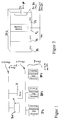
- FIG. 2 picks out a bus backplane from FIG. 1, the BP1, which contains an access module C1, which gives the bus backplane access to the network-oriented bus of level j + 1 (or in a further exemplary embodiment to the this higher-level bus of level j + 2).
- FIG. 3 illustrates a schematic view of a VME bus backplane, which is coupled down to an AT bus via a processor (a CPU) and which is connected upwards via VCOM to the local TCP / IP bus of level j + 1 of FIG. 1 can access.
- the BP1 is representative of a single machine, for example with 280 spinning positions. The communication level depicted is thus “inside the spinning machine", while the couplings to the outside (to the local bus) and to the other central units are "considered outside the machine”.
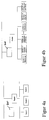
- FIG. 1 illustrates an exemplary combination of three bus backplanes BP1, BP2, BP3, which are interconnected on a local bus (level j + 1).
- a router R leads from the local bus to a higher-level bus, which is labeled "level j + 2" in FIG.
- a host system M is connected to it, which takes over the central administration of all routers R potentially coupled to the higher-level bus at level j + 2.
- the multiple routers R can result in an expanded system by supplementing the 4 components R, BP1, BP2, BP3 on the higher-level bus j + 2.
- the system of FIG. 1 is not limited to this extent.
- the system is also not limited in the number of BPi backplanes connected to the local bus of level j + 1, there can be a large number of these backplanes are connected there. However, all of these backplanes have the same data communication protocol that was selected in the example for TCP / IP. UDP / IP is also possible.
- backplane 1 is selected as an example. It shows that several central processing units (CPU) are connected to the backplane, in the example in FIG. 2 there are three CPUs P1, P2 and P3. One of these CPUs, here the CPU P1, is connected via the backplane BP1 to the Ethernet controller C1, which couples the backplane BP1 at the network level.
- the level j + 1 of FIG. 1 lying directly (logistically) above the backplane BP1 can be used as the network level;
- the level j + 2 of FIG. 1 can also be used as the level, which can be directly coupled to the backplane BP1 via a corresponding controller C.
- Both the one coupling and both couplings can be switched depending on the respective application; if both couplings are used, two network control devices (Ethernet controllers) C are used, one couples the backplane BP1 to the level j + 2, the other couples the backplane BP1 to the level j + 1.
- Ethernet controllers Ethernet controllers
- the backplane BP1 is schematically a hardware data bus and an address bus with an associated number of control lines. Overall, it is referred to as bus B1.
- each backplane BPi can contain a plurality of central units Pk, where k represents integers from 1 to p; p is therefore representative of a multiprocessor system that is installed on a backplane.
- a backplane is understood to be such a circuit board which has a plurality of layers in which the slots arranged on it are connected to lines. It can roughly be compared with a typical AT bus plate, which, however, is not multiprocessor-compatible, like the backplane BP of FIGS. 1 and 2. Only because of the multiprocessor capability is it possible for the communication protocol on the network of level j + 1 to be the communication protocol on the backplane.
- FIGS. 4a and 4b represent exemplary embodiments of the invention
- circuits of the prior art are explained in FIGS. 4a and 4b.
- FIG. 4a it was already explained at the beginning why this topology is time-consuming, collision-prone and not very structured.
- the network topology of FIG. 4b which would be a possible alternative to that of FIG. 4a, leaves unsettled responsibilities and unpredictable load problems between the individual functional units (referred to as node 1.1 to node n.3). This results from the fact that many functional units (nodes) do not come from the same manufacturer and are therefore constructed differently.
- Each of these nodes can have a different architecture, so that there are no similarities in the common network bus, which leads via the router to the host system, unless each of the systems would receive a correspondingly adapted network coupling card.
- This coupling card slows down the system and increases the likelihood of collisions, especially when the nodes 1.1, 1.2 and 1.3 belonging to, for example, a machine communicate with one another, the entire remaining bus being functionally blocked.
- FIG. 3 schematically realizes the backplane BP1 of FIG. 2 using a VME bus.
- a PC 80386 SX coupling card forms a connection in an AT bus, which is deterministic.
- the plug-in card VCOM forms the coupling C1 of FIG. 2, which leads from the backplane BP1 to the local bus of level j + 1 of FIG. 1.
- the local bus is that of level j + 1, not that of the backplane BP1.
- This bus is located on level j, one level below network level j + 1.
- Superordinate to the first network level j + 1 is level j + 2, which cannot be seen in FIG. 3, but which can be seen when several VCOMs are interconnected at network level j + 1 and a router R is local to them
- Bus j + 1 couples to the higher-level bus j + 2.
- VCOM of FIG. 3 represents the CPU P1 of FIG. 2 in the sketch of FIG. 3, as a direct router R to the higher-level bus of level j + 2.
- the router R is then physically contained in two separate cards, VM30 and VCOM.
Abstract
Description
- Das technische Gebiet der Erfindung sind die Spinnereimaschinen und dort ein Verfahren zum Steuern einer aus mehreren Spinnereimaschinen bestehenden Gruppe von Spinnereimaschinen ("Spinnereimaschinengruppe") und ein Steuerungsnetzwerk zum Aufbau einer Systemsteuerung der Spinnereimaschinengruppe.
- Eine Spinnereimaschine besteht aus einer Vielzahl von Spinnstellen, derzeit werden etwa 280 Spinnstellen zu einer Spinnereimaschine zusammengefaßt. Für viele Anwendungen ist es allerdings erforderlich, mehrere Spinnereimaschinen zusammenzuschalten, wobei die Steuerungszentrale ein erhebliches Gewicht bekommt. Geht man von der Spinnereimaschine R1 der Rieter AG gemäß Prospekt 1431 d vom November 1992 aus, so können bis zu 32 Rotor-Spinnmaschinen an die dortige Steuerungszentrale SCC II angeschlossen werden. Jede dieser Rotor-Spinnmaschinen kann bis zu 280 Spinnstellen haben. Daraus wird ersichtlich, welche Komplexität und Größe ein solches System annehmen kann, wenn zusätzlich mehrere Maschinengruppen der genannten Größe in Großspinnereien zusammengeschaltet werden, um einen Großverbund zu bilden.
- Es ist aus vorgenanntem Stand der Technik ersichtlich, daß eine Spinnereimaschinengruppe im Verbund mehrerer Spinnereimaschinen nur dann steuerbar und überwachbar bleibt, wenn man sich der Netzwerkstechnik bedient. Beispiele für mögliche Netzwerke im Stand der Technik sind die Figuren 4a, 4b, in denen zwei Topologien vereinfachend grafisch dargestellt werden. Diese Topologien arbeiten mit dem Netzwerk Ethernet, dessen Protokoll Stand der Technik ist und mit CSMA/CD (Carrier Sense Multiple Access with Collision Detect) bezeichnet wird. Es arbeitet so, daß eine Station (ein "Node") ein Daten- oder Informationspaket sendet, wenn sie zuvor geprüft hat, ob bereits ein anderer Node aktiv ist. Ist ein anderer Node (Knoten oder Station) aktiv, so wartet die erstgenannte solange, bis das Netzwerks-Kabel frei ist. Für den Fall, daß zwei oder mehrere Stationen durch Zufall gleichzeitig senden (sogenannte Kollisionen), erkennen sie dies durch aktives Vergleichen der gesendeten Daten und den auf dem Kabel gemessenen Daten. Sofern die gemessenen Daten mit den gesendeten Daten nicht übereinstimmen, wird der Sendevorgang unterbrochen und erst nach einer Wartezeit wiederholt. Die Wartezeit wird bei dem verwendeten Protokoll mit Hilfe eines Zufallsgenerators ermittelt, der bei Wiederholungen exponentiell ansteigende Verzögerungswerte liefert. Dadurch kann verhindert werden, daß zwei Stationen wiederholt die gleiche Wartezeit verwenden und so auf Dauerkollision geschaltet sind. Kollisionsfälle bringen Zeitverzögerung. Neben der Zeitverzögerung durch Kollisionsfälle ist an den bekannten Topologien auch erkennbar, daß eine Kopplung zwischen zwei Stationen (beispielsweise Node 1 und Node 2 oder Node 1.1 und Node 1.2) das Netzwerk für alle anderen Stationen blockiert, die während der Kommuikation von zwei Stationen nicht das Netzwerk verwenden können. Auch der eingezeichnete "Router" (Kommunikation vom unteren Netzwerk zum höherliegenden Netzwerk in Figur 4b), an dem der Host (auch mehrere Hosts) angekoppelt ist, belastet das Netzwerk.
- Um die Funktionsfähigkeit der im Stand der Technik beschriebenen Spinnereimaschinensteuerung (mit Netzwerk) zu verbessern und um das unmittelbare Zusammenwirken aller im Verbund geschalteter Elemente des Netzwerkes zu beschleunigen, schlägt die Erfindung vor, das Datenkommunikations-Protokoll zum Austausch und zur Übermittlung von Betriebsdaten und Meßwerten der höheren Kommunikationsebene auch auf der niedereren Kommunikationsebene zu verwenden (Anspruch 1). Zur Durchführung dieser Vereinheitlichung von Netzwerks-Protokollen wird vorgeschlagen, eine Bus-Backplane zu verwenden (Anspruch 7), auf der mehrere Komponenten, insbesondere mehrere CPUs (zentrale Recheneinheiten) miteinander gekoppelt sind. Je eine Bus-Backplane kann stellvertretend für eine Spinnereimaschine mit ihrer Vielzahl von Spinnstellen stehen (Anspruch 13).
- Die Datenkommunikation ermöglicht die verbesserte Steuerung der Maschinengruppe; ohne weiteres kann die Kommunikation auch zur Überwachung der Maschinengruppe verwendet werden.
- Die zuvor erwähnte hardware-technische Bus-Backplane ist nicht an eine bestimmte Architektur gebunden, es können Bus-Backplanes von Intel (Multibus I,II) oder Motorola (VME) oder andere verwendet werden. Die Bus-Backplane ist einerseits eng mit der Maschinensteuerung verwandt und andererseits eng mit dem Netzwerk. Die enge Kopplung durch den hardware-technischen Aufbau wird unterstützt durch die gewählte Software-Kopplung, bei der das Kommunikationsprotokoll auf der Bus-Backplane und das Kommunikationsprotokoll auf der höheren Kommunikationsebene dasselbe, insbesondere ein standardisiertes Protokoll ist (Anspruch 2, Anspruch 13).
- Das Bussystem mit der Backplane kann Interfaceschaltungen (Schnittstellen) verschiedenster Art aufnehmen.
- Mit der Erfindung wird ein nicht deterministischer Bus sehr nahe zur Spinnereimaschine herabgeführt, und zwar hardware-technisch so nahe, wie ein übliches Netzwerk (z.B. nach dem Ethernet-Prinzip) nicht reichen würde. Die Spinnereimaschine muß andererseits auch deterministische Aufgaben erfüllen können, die zeitkritisch sind. Dazu werden an der Bus-Backplane entsprechende Prozessoren angekoppelt, die deterministische Steuerungen und Regelungen und das äquidistante Erfassen von Abtastwerten ermöglichen. Vorteilhaft ist deshalb die Bus-Backplane als Multiprozessor-Bus-Backplane aufgebaut (Anspruch 3). Wird eine Mulitprozessor-Bus-Backplane verwendet, so ist das zugehörige Standardprotokoll ebenfalls multiprozessorfähig (Anspruch 2,6), z.B. entspricht es dem TCP/IP-Protokoll.
- Die Funktionsfähigkeit der Spinnereimaschinen-Steuerung wird mit der Erfindung in zeitlicher Hinsicht erheblich verbessert. Aber nicht nur die verbesserte Geschwindigkeit wird mit der Erfindung begründet, auch die bessere Strukturierung und flexiblere Verbindung von Bussystemkomponenten wird möglich, sogar bei Verwendung von Bus-Backplanes unterschiedlicher Herkunft (Anspruch 8). Trotz der gegebenen Widrigkeiten kann die Erfindung sowohl die eingangs angesprochenen Zugriffskonflikte vermeiden, als auch Servicefreundlichkeit zur Verfügung stellen und damit in erheblichem Maße die Programmierkosten senken. Auch wird das Netzwerk geringer durch "Overhead" belastet.
- Die Bus-Backplanes, die jeweils einer Spinnereimaschine zugeordnet sein können, können in einem lokalen Netzwerk zusammengeschaltet werden, so daß eine erste Gruppe von Spinnereimaschinen über diesen lokalen Bus miteinander gekoppelt ist (Anspruch 13). Mehrere der lokalen Busse können über jeweilige Router an ein übergeordnetes Netzwerk gekoppelt sein (Anspruch 14), so daß eine Haupt-Steuerung (Host) Zugriff über jeweilige Router auf jeweilige Unternetzwerke ("Subnets") hat, die ihrerseits in mehrere Bus-Backplanes strukturiert sind. Bus-Backplane und Subnet haben dieselbe Topologie (sprich: dasselbe Datenkommunikations-Protokoll), was die Kommuikation in erheblichem Maße beschleunigt und strukturell vereinfacht.
- Eine Netzwerks-Gestaltung, die für die meisten Netzwerks-Steuerungen von Spinnereimaschinen ausreicht, besteht aus drei Ebenen, der Ebene j, der Ebene j+1 und der Ebene j+2. Die Ebene j ist diejenige der Bus-Backplanes. Hier sind mehrere Bus-Backplanes BPi enthalten und über einen Netzwerks-Zugriff auf einen lokalen Bus geschaltet, der aus einem Kabel besteht. Der lokale Bus ist die höhere Ebene j+1. Das Datenkommunikations-Protokoll auf der Ebene j+1 und das in den Bus-Backplanes BPi - der Ebene j - ist dasselbe. Von der Ebene j+1 führt ein Router zu einer übergeordneten Ebene j+2, an der die Zentralsteuerung - der "Host" - angekoppelt ist. Es bestehen also drei Ebenen, die Ebene der Bus-Backplanes, die Ebene des lokalen Busses, der der höhergeordnete Bus ist, und die Ebene des Hosts, der am übergeordneten Bus angekoppelt ist. Zwischen der übergeordneten Ebene j+2 und der unmittelbar darunter liegenden Ebene j+1 besteht nicht dasselbe Datenkommunikations-Protokoll; nur zwischen der Ebene j+1 und der darunterliegenden Ebene - der Ebene j der Bus-Backplanes - besteht Protokollidentität.
- Die Verwendung des allgemeinen Index j zeigt, daß diese Konfiguration von Ebenen bei stärker hierarchisch gegliederten Systemen nach aufwärts und abwärts verschoben werden kann, zumeist sind allerdings drei Ebenen sinnvoll, um die Erfindung gezielt einsetzen zu können (Anspruch 11), von denen eine Ebene mit dem Protokoll einer typischen Netzwerksanwendung arbeitet und die beiden darunterliegenden Ebenen mit einem anderen Protokoll arbeiten, das zwar auch noch netzwerksfähig ist, das aber sehr eng an determinitischen Bussen orientiert ist.
- Das Verständnis der Erfindung erleichtern die beigefügten Figuren, anhand derer einige Ausführungsbeispiele erläutert werden sollen.
- Figur 1 ist ein Beispiel mit drei Bus-Backplanes BP1, BP2 und BP3 und drei hierarchisch gestaffelten Netzwerks-Bussen, Ebene j, Ebene j+1 und Ebene j+2, im Beispiel j=1.
- Figur 2 greift eine Bus-Backplane der Figur 1 heraus, die BP1, die einen Zugriffs-Baustein C1 enthält, der von der Bus-Backplane den Zugriff auf den netzwerks-orientierten Bus der Ebene j+1 (oder in einem weiteren Ausführungsbeispiel auf den diesem übergeordneten Bus der Ebene j+2) erlaubt.
- Figur 3 verdeutlicht in schematischer Ansicht eine VME-Bus-Backplane, die über einen Prozessor (eine CPU) auf einen AT-Bus abwärts gekoppelt ist und die aufwärts über VCOM auf den lokalen TCP/IP-Bus der Ebene j+1 der Figur 1 zugreifen kann. In diesem Beispiel ist die BP1 stellvertretend für eine einzelne Maschine, mit beispielsweise 280 Spinnstellen. Die bildlich dargestellte Kommunikationsebene ist also "innerhalb der Spinnereimaschine", während die Kopplungen nach außen (zum lokalen Bus) und zu den anderen zentralen Einheiten "als außerhalb der Maschine" angesehen werden.
- Die Figur 1 veranschaulicht eine beispielhafte Kombination von drei Bus-Backplanes BP1, BP2, BP3, die auf einem lokalen Bus (Ebene j+1) zusammengeschaltet werden. Von dem lokalen Bus führt ein Router R zu einem übergeordneten Bus, der in der Figur 1 mit "Ebene j+2" bezeichnet ist. An ihm ist ein Hostsystem M angeschlossen, der die Zentralverwaltung aller potentiell an den übergeordneten Bus der Ebene j+2 angekoppelten Router R übernimmt. Die mehreren Router R können sich in einem erweiterten System durch Ergänzung der 4 Komponenten R, BP1, BP2, BP3 an dem übergeordneten Bus j+2 ergeben. Das System der Figur 1 ist insoweit nicht beschränkt. Das System ist aber auch nicht in der Anzahl der angeschlossenen Backplanes BPi an dem lokalen Bus der Ebene j+1 beschränkt, es können eine Vielzahl dieser Backplanes dort angeschlossen sein. Alle diese Backplanes haben jedoch das gleiche Datenkommunikations-Protokoll, das im Beispiel zu TCP/IP gewählt ist. Ebenso ist UDP/IP möglich.
- Eine Backplane ist in Figur 2 herausgegriffen, beispielhaft ist die Backplane 1 (BP1) gewählt. An ihr ist erkennbar, daß mehrere Zentraleinheiten (CPU) an der Backplane angeschlossen sind, im Beispiel der Figur 2 sind es drei CPUs P1, P2 und P3. Eine dieser CPUs, hier die CPU P1 ist über die Backplane BP1 mit dem Ethernet-Controller C1 verbunden, der die Backplane BP1 auf Netzebene koppelt. Als Netzebene kommt die unmittelbar (logistisch) über der Backplane BP1 liegende Ebene j+1 der Figur 1 in Frage; als Ebene kommt aber auch die Ebene j+2 der Figur 1 in Frage, die über einen entsprechenden Controller C mit der Backplane BP1 direkt gekoppelt sein kann. Sowohl die jeweils eine Kopplung als auch beide Kopplungen sind abhängig von dem jeweiligen Anwendungsfall schaltbar; werden beide Kopplungen verwendet, so werden zwei Netzwerks-Steuereinrichtungen (Ethernet-Controller) C verwendet, einer koppelt die Backplane BP1 an die Ebene j+2, der andere koppelt die Backplane BP1 an die Ebene j+1.
- Die Backplane BP1 ist schematisch ein Hardware-Datenbus und ein Adressenbus mit einer zugehörigen Anzahl von Steuerleitungen. Insgesamt wird er als Bus B1 bezeichnet.
- Aus der Zusammenschau der Figuren 1 und 2 wird die Netzwerks-Topologie deutlich. In vertikaler Richtung sind drei Ebenen j, j+1 und j+2 dargestellt, wobei j im allgemeinen ganze Zahlen von 1 bis m darstellen kann. In horizontaler Richtung besteht die Ebene j aus mehreren Backplanes BPi, wobei i ganze Zahlen von 1 bis n annehmen kann. Jede Backplane BPi ihrerseits kann eine Mehrzahl von Zentraleinheiten Pk enthalten, wobei k ganze Zahlen von 1 bis p darstellt; p ist also Repräsentant für ein Multiprozessor-System, das auf einer Backplane installiert ist.
- Als Backplane wird eine solche Platine verstanden, die eine Mehrzahl von Lagen hat, in denen die auf ihr angeordneten Steckplätze mit Leitungen verbunden sind. Verglichen werden kann mit ihr im groben eine typische AT-Busplatte, die allerdings nicht multiprozessorfähig ist, wie die Backplane BP der Figuren 1 und 2. Erst durch die Multiprozessorfähigkeit wird es möglich, daß das Kommunikationsprotokoll auf dem Netz der Ebene j+1 dem Kommunikationsprotokoll auf der Backplane entspricht.
- Im Gegensatz zu den Figuren 1 und 2 sowie der noch zu erläuternden Figur 3, die Ausführungsbeispiele der Erfindungen darstellen, sind Schaltungen des Standes der Technik in den Figuren 4a und 4b erläutert. Zu der Figur 4a wurde eingangs schon erläutert, warum diese Topologie zeitintensiv, kollisionsträchtig und wenig strukturiert ist. Die Netzwerks-Topologie der Figur 4b, die eine mögliche Alternative zu derjenigen der Figur 4a wäre, läßt ungeklärte Verantwortlichkeiten und nicht kalkulierbare Lastprobleme zwischen den einzelnen Funktionseinheiten (als Node 1.1 bis Node n.3 bezeichnet). Das resultiert davon, daß viele Funktionseinheiten (Nodes) nicht vom selben Hersteller stammen und daher unterschiedlich aufgebaut sind. Jeder dieser Nodes kann eine unterschiedliche Architektur aufweisen, so daß im gemeinsamen Netzwerksbus, der über den Router zum Hostsystem führt, keine Gemeinsamkeiten bestehen, es sei denn jede der Systeme würde eine entsprechend angepaßte Netzwerks-Kopplungskarte erhalten. Diese Kopplungskarte verlangsamt das System und erhöht die Wahrscheinlichkeit von Kollisionen, besonders dann, wenn die zu beispielsweise einer Maschine gehörenden Nodes 1.1, 1.2 und 1.3 miteinander kommunizieren, wobei der gesamte restliche Bus funktionell blockiert wird.
- Demgegenüber schaffen die Netzwerks-Topologien mit der Backplane und dem gemeinsamen Datenkommunikations-Protokoll auf Backplane und übergeordneter Netzwerks-Verbindung Übersichtlichkeit, Kollisionsvermeidung und Geschwindigkeitserhöhung. Das verdeutlicht auch die Figur 3, die die Backplane BP1 der Figur 2 schematisch anhand eines VME-Busses realisiert. Eine Kopplungskarte PC 80386 SX bildet eine Verbindung in einen AT-Bus, der deterministisch ist. Die Steckkarte VCOM bildet die Kopplung C1 der Figur 2, die von der Backplane BP1 zu dem lokalen Bus der Ebene j+1 der Figur 1 führt.
- Um Mißverständnisse bei der Bezeichnung der Busse zu vermeiden, wird betont, daß der lokale Bus derjenige der Ebene j+1 ist, nicht derjenige der Backplane BP1. Dieser Bus befindet sich auf der Ebene j, eine Ebene unterhalb der Netzwerks-Ebene j+1. Der ersten Netzwerks-Ebene j+1 übergeordnet ist die Ebene j+2, die in der Figur 3 nicht ersichtlich ist, die aber dann erkennbar wird, wenn mehrere VCOM auf der Netzwerks-Ebene j+1 zusammengeschaltet werden und ein Router R diesen lokalen Bus j+1 auf den übergeordneten Bus j+2 koppelt.
- Neben der soeben skizzierten Variante ist es auch möglich, VCOM der Figur 3 zusammen mit VM30, der die CPU P1 der Figur 2 in der Skizze gemäß Figur 3 darstellt, als direkten Router R zum übergeordneten Bus der Ebene j+2 zu verwenden. Der Router R ist dann physisch in zwei getrennten Karten enthalten, VM30 und VCOM.
Claims (14)
- Verfahren zum Steuern einer Spinnerei-Maschinengruppe im Verbund mehrerer Spinnereimaschinen, die ihrerseits eine Vielzahl von Spinnstellen - insbesondere segmentiert in Sektionen - enthalten, bei dem Datenaustausch ("Kommunikation") auf mehreren Kommunikationsebenen (j;j=1...m) vorgesehen ist und das Datenkommunikations-Protokoll zum Austausch und zur Übermittlung von Betriebsdaten und Meßwerten der höheren Kommunikationsebene (Ebene j+1) auch auf der niedereren Kommunikationsebene (Ebene j) verwendet wird.
- Verfahren nach Anspruch 1, bei dem das Protokoll ein Standard-Protokoll, insbesondere das TCP/IP-Protokoll ist.
- Verfahren nach Anspruch 1 oder 2, bei dem
die niederere Kommunikationsebene (Ebene j) eine Mehrzahl von CPUs aufweist ("Multiprozessor-Ebene") und die höhere Kommunikationsebene (Ebene j+1) über einen Router (R) an eine übergeordnete Kommunikationsebene (Ebene j+2) gekoppelt ist. - Verfahren nach Anspruch 3, bei dem die übergeordnete Kommunikationsebene (Ebene j+2) diejenige ist, an der die Systemsteuerung (''Hostsystem) angekoppelt ist.
- Verfahren nach Anspruch 3 oder 4, bei dem eine CPU (P1) der niedereren Ebene (Ebene j) mit einer an ihren Bus (D1) gekoppelten Steuerung (C1) auf das Netz der höheren Ebene (Ebene j+1) und/oder über einen separaten Router (R) auf das Netz der übergeordneten Kommunikationsebene (Ebene j+2) zugreift, wobei die übergeordnete Kommunikationsebene über der höheren Kommunikationsebene liegt.
- Verfahren nach Anspruch 1 bis 5, bei dem das Datenkommunikations-Protokoll ein multiprozessorfähiges Protokoll ist.
- Spinnereimaschinen-Steuerungsnetzwerk zur Durchführung des Steuerverfahrens nach einem der vorhergehenden Ansprüche, bei dem
eine Kommunikationsebene (Ebene j; j=1...m) eine Bus-Backplane (BPi;i=1...n) aufweist, auf der mehrere Komponenten, insbesondere mehrere CPUs (Pk; k=1...p) miteinander gekoppelt sind. - Steuerungsnetzwerk nach Anspruch 7, bei dem
mehrere Bus-Backplanes, insbesondere unterschiedlicher Architektur vorgesehen sind. - Steuerungsnetzwerk nach Anspruch 7 oder 8, bei dem die Bus-Backplane (BPi) eine Mehrlagenplatine ist, auf der eine Mehrzahl von Steckplätzen für die Komponenten vorgesehen sind.
- Steuerungsnetzwerk nach einem der Ansprüche 7 bis 9, bei dem an der Bus-Backplane (BPi) mindestens eine Spinnereimaschinen-Steuerung und eine Garnüberwachung als Komponenten angeschlossen sind.
- Steuerungsnetzwerk nach einem der Ansprüche 7 bis 10, bei dem
die übergeordnete und die höhere Kommunikationsebene netzwerks-orientiert sind und zur Kopplung von Meßwerten und Befehlen eine Leitung vorgesehen ist. - Steuerungsnetzwerk nach einem der Ansprüche 7 bis 11, bei dem die Kommunikationsebene auf der Bus-Backplane die Kommunikationsebene einer Spinnmaschine mit einer Vielzahl von Spinnstellen ist.
- Steuerungsnetzwerk nach einem der Ansprüche 7 bis 12, bei dem
je Bus-Backplane (BPi) eine Spinnereimaschine angeschlossen ist und mehrere Bus-Backplanes (BP1 ...BP3) zu einem ersten lokalen Bus einer ersten lokalen Maschinengruppe und dieser lokale Bus über einen Router (R) an den übergeordneten Bus gekoppelt ist, wobei das Protokoll auf dem ersten lokalen Bus und das Protokoll auf den mehreren Bus-Backplanes (BP1...BP3) im wesentlichen identisch ist. - Steuerungsnetzwerk nach Anspruch 13, bei dem
mehrere Router (R) mehrere lokale Busse, von denen jeder einer Maschinengruppe entspricht, an das übergeordnete Netzwerk koppeln, um dort die Steuerung aller Spinnereimaschinen der Spinnerei über das übergeordnete Netzwerk (Ebene j+2) zu ermöglichen.
Priority Applications (7)
| Application Number | Priority Date | Filing Date | Title |
|---|---|---|---|
| EP94116825A EP0710904B1 (de) | 1994-10-25 | 1994-10-25 | Backplane-Steuerung für Spinnereimaschine |
| DE59407059T DE59407059D1 (de) | 1994-10-25 | 1994-10-25 | Backplane-Steuerung für Spinnereimaschine |
| US08/467,165 US5710708A (en) | 1994-10-25 | 1995-06-06 | Backplane control system for spinning machines |
| JP7244279A JPH08289377A (ja) | 1994-10-25 | 1995-09-22 | 紡績機械群を制御するための方法、及びそのシステム制御を構成するための制御ネットワ−ク |
| IT95MI002164A IT1276971B1 (it) | 1994-10-25 | 1995-10-20 | Comando a retroquadri per macchine di filatura |
| DE19539354A DE19539354A1 (de) | 1994-10-25 | 1995-10-23 | Backplane-Steuerung für Spinnereimaschine |
| CZ952786A CZ278695A3 (en) | 1994-10-25 | 1995-10-25 | Method of controlling a group of spinning machines and a control network for making the same |
Applications Claiming Priority (1)
| Application Number | Priority Date | Filing Date | Title |
|---|---|---|---|
| EP94116825A EP0710904B1 (de) | 1994-10-25 | 1994-10-25 | Backplane-Steuerung für Spinnereimaschine |
Publications (2)
| Publication Number | Publication Date |
|---|---|
| EP0710904A1 true EP0710904A1 (de) | 1996-05-08 |
| EP0710904B1 EP0710904B1 (de) | 1998-10-07 |
Family
ID=8216409
Family Applications (1)
| Application Number | Title | Priority Date | Filing Date |
|---|---|---|---|
| EP94116825A Revoked EP0710904B1 (de) | 1994-10-25 | 1994-10-25 | Backplane-Steuerung für Spinnereimaschine |
Country Status (6)
| Country | Link |
|---|---|
| US (1) | US5710708A (de) |
| EP (1) | EP0710904B1 (de) |
| JP (1) | JPH08289377A (de) |
| CZ (1) | CZ278695A3 (de) |
| DE (2) | DE59407059D1 (de) |
| IT (1) | IT1276971B1 (de) |
Cited By (2)
| Publication number | Priority date | Publication date | Assignee | Title |
|---|---|---|---|---|
| WO1999013388A1 (en) * | 1997-09-10 | 1999-03-18 | Square D Company | Apparatus for controlling internetwork communications |
| EP1340128B1 (de) * | 2000-12-05 | 2007-01-31 | Hirschmann Electronics GmbH & Co. KG | Verteilen von daten |
Families Citing this family (36)
| Publication number | Priority date | Publication date | Assignee | Title |
|---|---|---|---|---|
| US7949495B2 (en) * | 1996-03-28 | 2011-05-24 | Rosemount, Inc. | Process variable transmitter with diagnostics |
| US7630861B2 (en) * | 1996-03-28 | 2009-12-08 | Rosemount Inc. | Dedicated process diagnostic device |
| US8290721B2 (en) * | 1996-03-28 | 2012-10-16 | Rosemount Inc. | Flow measurement diagnostics |
| JP3722399B2 (ja) * | 1997-05-26 | 2005-11-30 | 東レエンジニアリング株式会社 | 糸条製造工程における張力監視方法 |
| US6587884B1 (en) * | 1997-09-10 | 2003-07-01 | Schneider Automation, Inc. | Dual ethernet protocol stack for maximum speed access to a programmable logic controller (PLC) |
| DE69818494T2 (de) | 1997-10-13 | 2004-07-01 | Rosemount Inc., Eden Prairie | Übertragungsmethode für Feldvorrichtungen in industriellen Prozessen |
| US7010459B2 (en) * | 1999-06-25 | 2006-03-07 | Rosemount Inc. | Process device diagnostics using process variable sensor signal |
| DE19954258A1 (de) | 1999-11-11 | 2001-05-17 | Truetzschler Gmbh & Co Kg | Vorrichtung zur elektronischen Steuerung von Spinnereimaschinen, insbesondere Spinnereivorbereitungsmaschinen |
| DE20004400U1 (de) | 2000-03-09 | 2001-07-19 | Cooper Power Tools Gmbh & Co | Betriebsnetzwerksystem |
| FR2811844B1 (fr) * | 2000-07-13 | 2002-11-29 | Schneider Automation S A | Bus interne automate supportant le protocole tcp/ip |
| US6671583B2 (en) | 2001-03-30 | 2003-12-30 | Helix Technology Corporation | Vacuum system information network |
| US6629059B2 (en) | 2001-05-14 | 2003-09-30 | Fisher-Rosemount Systems, Inc. | Hand held diagnostic and communication device with automatic bus detection |
| US7290450B2 (en) * | 2003-07-18 | 2007-11-06 | Rosemount Inc. | Process diagnostics |
| US7018800B2 (en) * | 2003-08-07 | 2006-03-28 | Rosemount Inc. | Process device with quiescent current diagnostics |
| US7627441B2 (en) * | 2003-09-30 | 2009-12-01 | Rosemount Inc. | Process device with vibration based diagnostics |
| US7523667B2 (en) * | 2003-12-23 | 2009-04-28 | Rosemount Inc. | Diagnostics of impulse piping in an industrial process |
| US8112565B2 (en) * | 2005-06-08 | 2012-02-07 | Fisher-Rosemount Systems, Inc. | Multi-protocol field device interface with automatic bus detection |
| US7835295B2 (en) | 2005-07-19 | 2010-11-16 | Rosemount Inc. | Interface module with power over Ethernet function |
| DE102005044733A1 (de) * | 2005-09-19 | 2007-03-22 | Maschinenfabrik Rieter Ag | Steuerung für Spinnmaschinen |
| US20070068225A1 (en) * | 2005-09-29 | 2007-03-29 | Brown Gregory C | Leak detector for process valve |
| US7953501B2 (en) | 2006-09-25 | 2011-05-31 | Fisher-Rosemount Systems, Inc. | Industrial process control loop monitor |
| WO2008042290A2 (en) | 2006-09-29 | 2008-04-10 | Rosemount Inc. | Magnetic flowmeter with verification |
| EP1935577A1 (de) * | 2006-12-21 | 2008-06-25 | Abb Ab | Steuersystem zur Steuerung eines Industrieroboters |
| DE102007032237A1 (de) * | 2007-07-11 | 2009-01-15 | Rieter Ingolstadt Gmbh | Textilmaschine |
| US8898036B2 (en) * | 2007-08-06 | 2014-11-25 | Rosemount Inc. | Process variable transmitter with acceleration sensor |
| US7590511B2 (en) * | 2007-09-25 | 2009-09-15 | Rosemount Inc. | Field device for digital process control loop diagnostics |
| DE102007052677B4 (de) * | 2007-11-05 | 2016-04-21 | Saurer Germany Gmbh & Co. Kg | Verfahren zum Betreiben einer eine Vielzahl von Arbeitsstellen aufweisenden Textilmaschine |
| DE102009057273A1 (de) * | 2009-12-08 | 2011-06-09 | Diehl Bgt Defence Gmbh & Co. Kg | Elektronische Baugruppe |
| US9207670B2 (en) | 2011-03-21 | 2015-12-08 | Rosemount Inc. | Degrading sensor detection implemented within a transmitter |
| JP2013067473A (ja) * | 2011-09-21 | 2013-04-18 | Murata Machinery Ltd | 糸巻取機 |
| US9052240B2 (en) | 2012-06-29 | 2015-06-09 | Rosemount Inc. | Industrial process temperature transmitter with sensor stress diagnostics |
| US9602122B2 (en) | 2012-09-28 | 2017-03-21 | Rosemount Inc. | Process variable measurement noise diagnostic |
| DE102012109669A1 (de) | 2012-10-11 | 2014-05-15 | Rieter Ingolstadt Gmbh | Textilmaschine, insbesondere Spinnmaschine oder Spulmaschine, mit einem Steuer- und Kommunikationssystem |
| CN104345694A (zh) * | 2013-07-30 | 2015-02-11 | 新安乃达驱动技术(上海)有限公司 | 细纱机纺纱控制系统 |
| KR101534433B1 (ko) * | 2014-02-03 | 2015-07-06 | 영남대학교 산학협력단 | 방적기 제어장치 |
| CH711592B1 (it) | 2014-07-31 | 2020-06-30 | Camozzi Digital S R L | Procedimento di identificazione di malfunzionamenti o degradazione del funzionamento di una macchina tessile. |
Citations (1)
| Publication number | Priority date | Publication date | Assignee | Title |
|---|---|---|---|---|
| EP0135881A2 (de) * | 1983-09-19 | 1985-04-03 | Siemens Aktiengesellschaft | Speicherprogrammierbares Automatisierungsgerät |
Family Cites Families (8)
| Publication number | Priority date | Publication date | Assignee | Title |
|---|---|---|---|---|
| US4835699A (en) * | 1987-03-23 | 1989-05-30 | Burlington Industries, Inc. | Automated distributed control system for a weaving mill |
| JP2834122B2 (ja) * | 1987-07-08 | 1998-12-09 | 株式会社日立製作所 | 制御装置 |
| DE3924779A1 (de) * | 1989-07-26 | 1991-01-31 | Rieter Ag Maschf | Verfahren und vorrichtung zum betrieb einer spinnereilinie |
| GB9006661D0 (en) * | 1990-03-24 | 1990-05-23 | Reflex Manufacturing Systems L | Network-field interface for manufacturing systems |
| JPH047269A (ja) * | 1990-04-24 | 1992-01-10 | Murata Mach Ltd | 紡績工場における品質管理システム |
| IT1246039B (it) * | 1990-07-10 | 1994-11-07 | Tiziano Barea | Disopositivo per il controllo del funzionamento di macchine in particolare di macchine tessili in grado di autoapprendere il ciclo operativo di queste ultime e di correggere i propi errori in tale fase di autoapprendimento |
| JP3242915B2 (ja) * | 1991-01-23 | 2001-12-25 | マシーネンファブリク リーター アクチェンゲゼルシャフト | 繊維処理プラント紡績工場および紡績機械 |
| DE69316009T2 (de) * | 1992-06-12 | 1998-04-23 | Dow Chemical Co | Sicheres frontendverbindungssystem und verfahren fur prozesssteuerungsrechner |
-
1994
- 1994-10-25 DE DE59407059T patent/DE59407059D1/de not_active Revoked
- 1994-10-25 EP EP94116825A patent/EP0710904B1/de not_active Revoked
-
1995
- 1995-06-06 US US08/467,165 patent/US5710708A/en not_active Expired - Fee Related
- 1995-09-22 JP JP7244279A patent/JPH08289377A/ja active Pending
- 1995-10-20 IT IT95MI002164A patent/IT1276971B1/it active IP Right Grant
- 1995-10-23 DE DE19539354A patent/DE19539354A1/de not_active Withdrawn
- 1995-10-25 CZ CZ952786A patent/CZ278695A3/cs unknown
Patent Citations (1)
| Publication number | Priority date | Publication date | Assignee | Title |
|---|---|---|---|---|
| EP0135881A2 (de) * | 1983-09-19 | 1985-04-03 | Siemens Aktiengesellschaft | Speicherprogrammierbares Automatisierungsgerät |
Non-Patent Citations (8)
| Title |
|---|
| J.-D. DECOTIGNIE: "Integrating the Numerical Controller and the FMS", 15TH ANNUAL CONFERENCE OF IEEE INDUSTRIAL ELECTRONICS SOCIETY, VOLUME I - POWER ELECTRONICS, 6 November 1989 (1989-11-06), PHILADELPHIA, USA, pages 675 - 680, XP000130574 * |
| KOZIOL ET AL.: "CIE INTEGRATED SYSTEM FOR THE CPCM (COUPLED PICKLE LINE AND TANDEM COLD MILL) AT DOFASCO'S HAMILTON WORKS", CONFERENCE RECORD OF THE 1993 IEEE INDUSTRY APPLICATIONS CONFERENCE TWENTY-EIGHTH IAS ANNUAL MEETING, PART III, 3 October 1993 (1993-10-03), TORONTO, CANADA, pages 2388 - 2392, XP000420464 * |
| LARS-BERNO FREDRIKSSON: "CONTROLLER AREA NETWORKS AND THE PROTOCOL CAN FOR MACHINE CONTROL SYSTEMS", MECHATRONICS, vol. 4, no. 2, March 1994 (1994-03-01), OXFORD GB, pages 159 - 172, XP000448925 * |
| P. SKOKOWSKI: "Penny-Pinching Networks for Distributed Control", CONTROL ENGINEERING, vol. 39, no. 5, 15 March 1992 (1992-03-15), NEW YORK US, pages 35 - 37, XP000296074 * |
| R. MÜLLER: "LON - das universelle Netzwerk, Teil 1", ELEKTRONIK, vol. 40, no. 22, October 1991 (1991-10-01), MUNCHEN DE, pages 59 - 69, XP000268228 * |
| R. S. HASKELL ET AL.: "Computer Integrated Controller for Numerically Controlled Machines and Process Tools", IBM TECHNICAL DISCLOSURE BULLETIN, vol. 37, no. 7, July 1994 (1994-07-01), NEW YORK, USA, pages 261 - 264, XP000455506 * |
| T. COFFEY: "FACTORY AUTOMATION NETWORKING STANDARDS FOR DISTRIBUTED MANUFACTORING", 24TH ISATA INTERNATIONAL SYMPOSIUM ON AUTOMOTIVE TECHNOLOGY AND AUTOMATION, 20 May 1991 (1991-05-20), FLORENCE, ITALY, pages 585 - 598, XP000308658 * |
| W. MÜNCH: "Unterstützen TCP/IP- und ISO/OSI-Protokolle", ELEKTRONIK, vol. 40, no. 23, 12 November 1991 (1991-11-12), MUNCHEN DE, pages 200 - 206, XP000267157 * |
Cited By (2)
| Publication number | Priority date | Publication date | Assignee | Title |
|---|---|---|---|---|
| WO1999013388A1 (en) * | 1997-09-10 | 1999-03-18 | Square D Company | Apparatus for controlling internetwork communications |
| EP1340128B1 (de) * | 2000-12-05 | 2007-01-31 | Hirschmann Electronics GmbH & Co. KG | Verteilen von daten |
Also Published As
| Publication number | Publication date |
|---|---|
| CZ278695A3 (en) | 1996-05-15 |
| ITMI952164A0 (de) | 1995-10-20 |
| DE59407059D1 (de) | 1998-11-12 |
| JPH08289377A (ja) | 1996-11-01 |
| US5710708A (en) | 1998-01-20 |
| ITMI952164A1 (it) | 1997-04-20 |
| IT1276971B1 (it) | 1997-11-03 |
| DE19539354A1 (de) | 1996-05-02 |
| EP0710904B1 (de) | 1998-10-07 |
Similar Documents
| Publication | Publication Date | Title |
|---|---|---|
| EP0710904B1 (de) | Backplane-Steuerung für Spinnereimaschine | |
| EP1309920B1 (de) | Adressvergabeverfahren für mindestens einen neu an ein bussystem angeschlossenen busteilnehmer | |
| EP1456722B1 (de) | Datenübertragungsverfahren, serielles bussystem und anschalteinheit für einen passiven busteilnehmer | |
| DE69305203T3 (de) | Flexibele Kommunikationsarchitektur für ein Bewegungssteuerungssystem | |
| DE3043894C2 (de) | ||
| DE69334172T2 (de) | Verfahren und Vorrichtung zur Arbitrierung auf einen acyclischen gerichteten Graph | |
| DE4121446C2 (de) | Terminal-Server-Architektur | |
| DE3820544C2 (de) | Ortsbereichsnetzsystem mit einem hiermit gekoppelten Mehrcomputersystem und Verfahren zur Steuerung hiervon | |
| DE69332778T2 (de) | Verfahren und geraet mit einzigadressenzuweisung, knotenselbstidentifizierung und topologieabbildung fuer einen gerichteten, acyclischen graph | |
| DE102006061063A1 (de) | Redundantes Überwachungssteuersystem, und Redundanzschaltverfahren des Gleichen | |
| EP0275992A2 (de) | Maschinenanlage mit mehreren Aktoren | |
| DE19756564A1 (de) | Nachrichtennetz mit automatischer Knotenkonfiguration bei identischen Knoten | |
| DE102004030561B4 (de) | Übertragungsvorrichtung für Schienenfahrzeugwagen | |
| EP3679691B1 (de) | Datenübertragungsverfahren und kommunikationsnetzwerk | |
| EP0019757A1 (de) | Datenverarbeitungsanlage, bei der mehrere Vorrechner und ein den Vorrechnern übergeordneter Hauptrechner in einer Baumstruktur angeordnet sind | |
| WO1992017962A1 (de) | Verfahren zum aufbau von botschaften für den datenaustausch und/oder für die synchronisation von prozessen in datenverarbeitungsanlagen | |
| DE3942639A1 (de) | System und vefahren an fahrzeugen zur nachrichtenuebertragung zwischen datenverarbeitungsstationen | |
| EP3575899B1 (de) | Automatisierungssystem, betriebsverfahren für automatisierungssystem und computerprogrammprodukt | |
| EP0113379B1 (de) | Rechnerkopplung | |
| DE10307424A1 (de) | Datenvermittlungsvorrichtung und Multiplex-Kommunikationssysteme | |
| EP1642207B1 (de) | Zuordnung von stationsadressen zu kommunikationsteilnehmern in einem bussystem | |
| DE19830803C2 (de) | CAN-Modul | |
| DE102019125545B3 (de) | Datenübertragungsverfahren, segment-telegramm und automatisierungskommunikationsnetzwerk | |
| DE60215910T2 (de) | Verfahren zur Bestimmung einer aktiven oder passiven Rollenzuteilung für ein Netzelementsteuerungsmittel | |
| EP0587918A1 (de) | Multiprozessorsystem mit Cache-Speichern |
Legal Events
| Date | Code | Title | Description |
|---|---|---|---|
| PUAI | Public reference made under article 153(3) epc to a published international application that has entered the european phase |
Free format text: ORIGINAL CODE: 0009012 |
|
| 17P | Request for examination filed |
Effective date: 19950214 |
|
| AK | Designated contracting states |
Kind code of ref document: A1 Designated state(s): AT BE CH DE DK ES FR GB GR IE IT LI LU MC NL PT SE |
|
| 17Q | First examination report despatched |
Effective date: 19970127 |
|
| GRAG | Despatch of communication of intention to grant |
Free format text: ORIGINAL CODE: EPIDOS AGRA |
|
| GRAG | Despatch of communication of intention to grant |
Free format text: ORIGINAL CODE: EPIDOS AGRA |
|
| GRAH | Despatch of communication of intention to grant a patent |
Free format text: ORIGINAL CODE: EPIDOS IGRA |
|
| GRAH | Despatch of communication of intention to grant a patent |
Free format text: ORIGINAL CODE: EPIDOS IGRA |
|
| GRAA | (expected) grant |
Free format text: ORIGINAL CODE: 0009210 |
|
| AK | Designated contracting states |
Kind code of ref document: B1 Designated state(s): BE CH DE FR IT LI |
|
| PG25 | Lapsed in a contracting state [announced via postgrant information from national office to epo] |
Ref country code: IT Free format text: LAPSE BECAUSE OF FAILURE TO SUBMIT A TRANSLATION OF THE DESCRIPTION OR TO PAY THE FEE WITHIN THE PRE;WARNING: LAPSES OF ITALIAN PATENTS WITH EFFECTIVE DATE BEFORE 2007 MAY HAVE OCCURRED AT ANY TIME BEFORE 2007. THE CORRECT EFFECTIVE DATE MAY BE DIFFERENT FROM THE ONE RECORDED.SCRIBED TIME-LIMIT Effective date: 19981007 Ref country code: FR Free format text: LAPSE BECAUSE OF FAILURE TO SUBMIT A TRANSLATION OF THE DESCRIPTION OR TO PAY THE FEE WITHIN THE PRESCRIBED TIME-LIMIT Effective date: 19981007 |
|
| REG | Reference to a national code |
Ref country code: CH Ref legal event code: EP |
|
| PG25 | Lapsed in a contracting state [announced via postgrant information from national office to epo] |
Ref country code: LI Free format text: LAPSE BECAUSE OF NON-PAYMENT OF DUE FEES Effective date: 19981031 Ref country code: CH Free format text: LAPSE BECAUSE OF NON-PAYMENT OF DUE FEES Effective date: 19981031 Ref country code: BE Free format text: LAPSE BECAUSE OF NON-PAYMENT OF DUE FEES Effective date: 19981031 |
|
| REF | Corresponds to: |
Ref document number: 59407059 Country of ref document: DE Date of ref document: 19981112 |
|
| EN | Fr: translation not filed | ||
| BERE | Be: lapsed |
Owner name: RIETER INGOLSTADT SPINNEREIMASCHINENBAU A.G. Effective date: 19981031 |
|
| REG | Reference to a national code |
Ref country code: CH Ref legal event code: PL |
|
| PLAV | Examination of admissibility of opposition |
Free format text: ORIGINAL CODE: EPIDOS OPEX |
|
| PLBI | Opposition filed |
Free format text: ORIGINAL CODE: 0009260 |
|
| 26 | Opposition filed |
Opponent name: TRUETZSCHLER GMBH & CO. KG Effective date: 19990602 |
|
| PLBF | Reply of patent proprietor to notice(s) of opposition |
Free format text: ORIGINAL CODE: EPIDOS OBSO |
|
| PLBF | Reply of patent proprietor to notice(s) of opposition |
Free format text: ORIGINAL CODE: EPIDOS OBSO |
|
| PLBF | Reply of patent proprietor to notice(s) of opposition |
Free format text: ORIGINAL CODE: EPIDOS OBSO |
|
| RDAF | Communication despatched that patent is revoked |
Free format text: ORIGINAL CODE: EPIDOSNREV1 |
|
| APBP | Date of receipt of notice of appeal recorded |
Free format text: ORIGINAL CODE: EPIDOSNNOA2O |
|
| APBQ | Date of receipt of statement of grounds of appeal recorded |
Free format text: ORIGINAL CODE: EPIDOSNNOA3O |
|
| APAA | Appeal reference recorded |
Free format text: ORIGINAL CODE: EPIDOS REFN |
|
| APAH | Appeal reference modified |
Free format text: ORIGINAL CODE: EPIDOSCREFNO |
|
| PGFP | Annual fee paid to national office [announced via postgrant information from national office to epo] |
Ref country code: DE Payment date: 20051025 Year of fee payment: 12 |
|
| APBU | Appeal procedure closed |
Free format text: ORIGINAL CODE: EPIDOSNNOA9O |
|
| RDAG | Patent revoked |
Free format text: ORIGINAL CODE: 0009271 |
|
| STAA | Information on the status of an ep patent application or granted ep patent |
Free format text: STATUS: PATENT REVOKED |
|
| 27W | Patent revoked |
Effective date: 20060725 |