EP0712551B1 - Universelles mobil-telekommunikationssystem - Google Patents
Universelles mobil-telekommunikationssystem Download PDFInfo
- Publication number
- EP0712551B1 EP0712551B1 EP94922844A EP94922844A EP0712551B1 EP 0712551 B1 EP0712551 B1 EP 0712551B1 EP 94922844 A EP94922844 A EP 94922844A EP 94922844 A EP94922844 A EP 94922844A EP 0712551 B1 EP0712551 B1 EP 0712551B1
- Authority
- EP
- European Patent Office
- Prior art keywords
- miz
- telecommunications system
- cordless
- cell
- tks
- Prior art date
- Legal status (The legal status is an assumption and is not a legal conclusion. Google has not performed a legal analysis and makes no representation as to the accuracy of the status listed.)
- Expired - Lifetime
Links
- 101150108382 NIS1 gene Proteins 0.000 claims description 11
- 102100026396 ADP/ATP translocase 2 Human genes 0.000 claims description 6
- 102100026397 ADP/ATP translocase 3 Human genes 0.000 claims description 6
- 101000718417 Homo sapiens ADP/ATP translocase 2 Proteins 0.000 claims description 6
- 101000718437 Homo sapiens ADP/ATP translocase 3 Proteins 0.000 claims description 6
- 230000005540 biological transmission Effects 0.000 abstract description 33
- 238000004891 communication Methods 0.000 description 24
- 230000001413 cellular effect Effects 0.000 description 14
- 238000000034 method Methods 0.000 description 10
- 238000011161 development Methods 0.000 description 7
- 230000018109 developmental process Effects 0.000 description 7
- 238000010295 mobile communication Methods 0.000 description 6
- 230000000694 effects Effects 0.000 description 5
- 230000035992 intercellular communication Effects 0.000 description 4
- 230000008878 coupling Effects 0.000 description 3
- 238000010168 coupling process Methods 0.000 description 3
- 238000005859 coupling reaction Methods 0.000 description 3
- 102100032533 ADP/ATP translocase 1 Human genes 0.000 description 2
- 101000768061 Escherichia phage P1 Antirepressor protein 1 Proteins 0.000 description 2
- 101000796932 Homo sapiens ADP/ATP translocase 1 Proteins 0.000 description 2
- 230000008901 benefit Effects 0.000 description 2
- 238000005516 engineering process Methods 0.000 description 2
- 230000010354 integration Effects 0.000 description 2
- 230000002452 interceptive effect Effects 0.000 description 2
- 230000004048 modification Effects 0.000 description 2
- 238000012986 modification Methods 0.000 description 2
- 238000012546 transfer Methods 0.000 description 2
- 241000599985 Beijerinckia mobilis Species 0.000 description 1
- 101001074629 Homo sapiens E3 SUMO-protein ligase PIAS2 Proteins 0.000 description 1
- 101001072590 Homo sapiens POZ-, AT hook-, and zinc finger-containing protein 1 Proteins 0.000 description 1
- 101000964478 Homo sapiens Zinc finger and BTB domain-containing protein 17 Proteins 0.000 description 1
- 102100036665 POZ-, AT hook-, and zinc finger-containing protein 1 Human genes 0.000 description 1
- 102100040761 Zinc finger and BTB domain-containing protein 17 Human genes 0.000 description 1
- 230000009471 action Effects 0.000 description 1
- 238000013016 damping Methods 0.000 description 1
- 230000006735 deficit Effects 0.000 description 1
- 230000001419 dependent effect Effects 0.000 description 1
- 230000036541 health Effects 0.000 description 1
- 230000007774 longterm Effects 0.000 description 1
- 230000008569 process Effects 0.000 description 1
- 238000000926 separation method Methods 0.000 description 1
- 238000006467 substitution reaction Methods 0.000 description 1
- 238000012549 training Methods 0.000 description 1
Images


Classifications
-
- H—ELECTRICITY
- H04—ELECTRIC COMMUNICATION TECHNIQUE
- H04W—WIRELESS COMMUNICATION NETWORKS
- H04W84/00—Network topologies
- H04W84/02—Hierarchically pre-organised networks, e.g. paging networks, cellular networks, WLAN [Wireless Local Area Network] or WLL [Wireless Local Loop]
- H04W84/10—Small scale networks; Flat hierarchical networks
- H04W84/14—WLL [Wireless Local Loop]; RLL [Radio Local Loop]
-
- H—ELECTRICITY
- H04—ELECTRIC COMMUNICATION TECHNIQUE
- H04B—TRANSMISSION
- H04B7/00—Radio transmission systems, i.e. using radiation field
- H04B7/24—Radio transmission systems, i.e. using radiation field for communication between two or more posts
- H04B7/26—Radio transmission systems, i.e. using radiation field for communication between two or more posts at least one of which is mobile
- H04B7/2603—Arrangements for wireless physical layer control
- H04B7/2606—Arrangements for base station coverage control, e.g. by using relays in tunnels
-
- H—ELECTRICITY
- H04—ELECTRIC COMMUNICATION TECHNIQUE
- H04W—WIRELESS COMMUNICATION NETWORKS
- H04W16/00—Network planning, e.g. coverage or traffic planning tools; Network deployment, e.g. resource partitioning or cells structures
- H04W16/24—Cell structures
-
- H—ELECTRICITY
- H04—ELECTRIC COMMUNICATION TECHNIQUE
- H04W—WIRELESS COMMUNICATION NETWORKS
- H04W16/00—Network planning, e.g. coverage or traffic planning tools; Network deployment, e.g. resource partitioning or cells structures
- H04W16/24—Cell structures
- H04W16/26—Cell enhancers or enhancement, e.g. for tunnels, building shadow
Definitions
- the invention relates to a universal mobile telecommunications system according to the preamble of claim 1.
- Modern mobile communication e.g. B. mobile telecommunications to transmit voice, data, text, graphics, fixed and moving image is analogous to the fixed communication (e.g., ISDN communication system;. Integrated Services Digital Network) in a private and public Area divided.
- a distinction is also made in mobile telecommunications (first and second generation) between cellular and cordless telecommunications.
- cordless telecommunications has essentially relied on cordless telecommunications systems for home and office applications, while cellular telecommunications are primarily determined by the use of mobile telecommunications systems.
- a TDMA method Time Division Multiple Access
- a TDMA transmission method for future mobile telecommunications systems but also the CDMA transmission method (C ode D Division Multiple ccess), not least because of the expected use of the cell-oriented transmission procedure (ATM method; A synchronus T ransfer M ode) gain in importance.
- ATM method A synchronus T ransfer M ode
- the optimized signal coding and channel coding for a flexible air interface will play an increasingly important role.
- the TDMA and CDMA transmission processes ultimately form the basis for the various system standards in mobile telecommunications.
- the cordless telecommunication systems currently launched on the market are built, among others, according to the digital pan-European DECT standard ( D igital E uropean C ordless T elecommunication) and the digital CT2 standard ( C ordless T elephone 2 ), while the mobile radio telecommunications systems to the international GSM standard (G roupe S fuge M obile; G lobal S ystem for M obile communications) are constructed.
- GSM Global System for Mobile Communications
- UMTS Universal Mobile Telecommunications System
- UPT U niversal P ersonal T elecommunication
- UMTS U niversal P ersonal T elecommunication
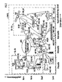
- FIG. 2 starting from the Telcom Report 15; 1992; Issue 2, pages 60 to 63 shows a scenario "Universal Mobile Communication - Advanced Mobility” with the various applications in relation to the cell radius.
- the structure of the universal mobile telecommunications system (UMTS) is then divided into different communication cells for the application areas (office, home, city and country). These cells can be linked two (country, city) or three-dimensionally (building).
- the different types of mobile telecommunications cordless, mobile radio and satellite telecommunications SL-TK, MF-TK, S-TK
- SL-TK local area network
- MF-TK MF-TK
- S-TK satellite telecommunications
- the cordless telecommunications SL-TK takes place in its pure, separate form for office and home applications in the picocell area.
- this picocell area with a picocell radius PIZR of up to 200 m (transmission range) - there is at least one picocell PIZ with a cordless telecommunication system SL-TKS.
- the cordless telecommunication system SL-TKS consists of a picocell-specific base station PIZ-BS (Cordless base station) and at least one picocell-specific mobile station PIZ-MS (cordless mobile station) assigned to the base station PIZ-BS.
- cell-specific / s / s are used in connection with an object / an activity / a property, then this means the object / the activity / the property that one Cell (e.g. a pico, micro, macro and hyper cell) is inherent or belongs to a cell.
- Cell e.g. a pico, micro, macro and hyper cell
- the mobile telecommunications MF-TK takes place in its pure, separate form for urban or rural applications in stationary goods (e.g. buildings) and / or in dynamic, movable goods (e.g. car, train etc.) in the Macro cell area instead.
- this macro cell area with a macro cell radius MAZR of z. B. up to 20 km (transmission range) -, which includes the picocell area with the picocell PIZ and a microcell area with at least one microcell MIZ, there is at least one macrocell MAZ with a mobile telecommunications system MF-TKS.
- This mobile telecommunication system MF-TKS consists of a macro cell-specific base station MAZ-BS (cell phone base station), which can be stationary or mobile (e.g. car, train), and at least one macro cell-specific mobile station assigned to the base station MAZ-BS MAZ-MS (cellular mobile station).
- MAZ-BS cell phone base station
- MAZ-MS cellular mobile station
- the satellite telecommunications SF-TK takes place in a hypercell area.
- this hypercell area - with a hypercell radius HYZR of several hundred kilometers (transmission range) - there is at least one hypercell HYZ with a satellite telecommunication system SF-TKS.
- This satellite telecommunications system SF-TKS consists of a z. B. Positioned on the geostationary earth orbit satellite SAT of a hypercell-specific base station HYZ-BS, which is stationary Earth station ES or mobile as a mobile earth station MES (e.g. in an airplane, ship, truck, etc.), and at least one hyper cell-specific mobile station HYZ-MS assigned to the base station HYZ-BS.
- NISDN Integrated Services Digital Network
- B-ISDN B reitband- Integrated Services Digital Network
- This network infrastructure NIS is, for example, a narrowband or broadband ISDN communication system.
- This network infrastructure NIS is with the picocell-specific base stations PIZ-BS of the cordless telecommunication system SL-TKS, the macro-cell-specific base stations MAZ-BS of the mobile telecommunication system MF-TKS and / or via the stationary earth station ES with the satellite SAT of the satellite telecommunication system SF- DCS connected bidirectionally.
- UMTS universal mobile telecommunication system
- cellular interactive telecommunication cellular
- cordless interactive telecommunication cordless technology
- UMTS universal mobile communication
- EP 0 418 096 A2 discloses a cellular mobile radio system (macro cell) which is subdivided into a number of subcells (picocells). Each of these sub-cells is assigned a duplex repeater station, by means of which a macro-cell-specific radio connection can be established between a macro-cell-specific base station and a low-power mobile unit assigned to the sub-cells.
- the duplex repeater station has the task of receiving, converting and amplifying radio signals transmitted from the low-power mobile parts to the macro cell-specific base station and of receiving, converting and damping radio signals transmitted from the macro cell-specific base station to the low-power mobile parts (tasks of a transponder ).
- Portable telephones are known from US Pat. No. 4,748,655, which comes closest to the application, and can be connected via a large number of different network coupling devices (gateways), such as. B. common radio units, radio telephones, cordless telephones or private branch exchanges that can be connected to a cellular radio network.
- the portable telephone can also be used as a radio paging receiver within the cellular radio network. The user of such a multifunctional telephone can thus participate in the network telecommunication without having a radio telephone required for the telecommunication in the cellular radio network. This participation is ensured by the various network coupling devices.
- the common radio unit which is designed as a multi-channel arrangement, is in particular able to operate a large number of the multifunctional telephones mentioned within a smaller, smaller area than the cells of the radio network.
- the preferably portable and z. B. in public areas such as train stations, airports, trains or buses shared radio unit is used for the above-mentioned telecommunications purposes exclusively as a connection and implementation unit between a base station assigned to the cellular radio network and the multifunctional telephones.
- the mode of operation of the common radio unit thus corresponds to a transponder as is known, for example, from satellite technology.
- a cellular radio telephone system is known from US Pat. No. 4,759,051, in which a geographical radio area with a central cell station is divided into several radio cells. Each of these radio cells contains a transponder, the transponder on the radio link between portable radio units and the cell station receiving, amplifying and releasing the radio signals to be transmitted.
- the object on which the invention is based is to specify a universal mobile telecommunications system in which, in the course of the further development of mobile telecommunications in accordance with the spiral of activity according to FIG. 1, a cordless telecommunications system which is individual to the picocell can be expanded to communication cells with different cell radii (universal).
- the main advantage of the universal mobile telecommunication system according to the invention is that it extends to communication cells with different cell radii Cordless telecommunication system in the extended cordless range manages with a lower transmission power for cordless mobile stations and thereby reduces the load on a user of the cordless mobile station by electromagnetic waves during cordless transmission.
- Another significant advantage of the universal mobile telecommunication system according to the invention is that the extended cordless telecommunication system, in particular in the picocell and micro cell area, gives the possibility for telephony with higher quality up to telephony with pictures. This is due to the fact that the smaller the cell radius of a communication cell, the greater the capacity available per unit area and thus the usable bit rate for the respective application.
- the universal mobile telecommunication system according to the invention thus already offers, in the course of the spiral of action for universal mobile telecommunication with advanced mobility, a simple possibility of connecting cellular and cordless mobile telecommunication systems with one another.
- a universal mobile telecommunication system can be set up in which a telecommunication subscriber can reach his communication partner anywhere (advanced mobility).
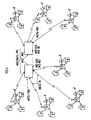
- FIG. 3 shows a cordless telecommunication system MIZSL-TKS extended to a microcell MIZ of the microcell area according to FIG.
- the micro cell MIZ is a communication room, in the communication center of which - in the case of the micro cell MIZ - a micro cell-specific transmission / reception arrangement MIZ-SEA is arranged.
- the entire micro-cell-specific cordless telecommunications MIZSL-TK is processed via this transmit / receive arrangement MIZ-SEA.
- the transmitting / receiving arrangement MIZ-SEA is z. B. designed as a micro-cell base station MIZ-BS.
- the transmitting / receiving arrangement MIZ-SEA is assigned at least one picocell PIZ for a cell-cell-specific cordless telecommunications SL-TK according to FIG. 2, each via a micro-cell-specific cordless connection MIZ-SLV.
- the number of picocells PIZ which are assigned to the transmitting / receiving arrangement MIZ-SEA via the corresponding number of cordless connections MIZ-SLV depends in particular on how large the communication subscriber density (traffic density) in the microcell MIZ is.
- the number of picocells PIZ is rather small, while in heavily populated ones Regions (microcells) the number of picocells PIZ with the associated microcell-specific cordless connections MIZ-SLV is large.
- the number of picocells PIZ is not only dependent on the density of communication participants, but is also based on the transmission capacity available in the MIZ-SEA transmission / reception arrangement. This transmission capacity is essentially determined by the number of transmission channels. For example, a maximum of twelve transmission channels (half-duplex transmission channels) are currently available for the PIZSL-TKS, MIZSL-TKS pico or micro cell-specific cordless telecommunication systems built according to the DECT standard.
- m 4 picocells PIZ (PIZ1 ... PIZ4) via four micro-cell-specific cordless connections MIZ-SLV (MIZ-SLV1 ... MIZ-SLV4) of the transmit / Receiving arrangement assigned to MIZ-SEA.
- the maximum distance at which these picocells PIZ1 ... PIZ4 can be removed from the transmit / receive arrangement MIZ-SEA is determined by the microcell radius MIZR, which is assigned to the microcell MIZ by definition.
- This micro cell radius MIZR is, for example, 2000 m. So are in Figure 3 Pico cell PIZ1 via the micro cell-specific cordless connection MIZ-SLV1 with a micro cell radius MIZR1 of e.g. B.
- PIZ4 are structured apart from the fact that they can be located differently from the transmit / receive arrangement MIZ-SEA, otherwise with respect to the picocell-specific cordless telecommunications PIZSL-TK.
- a relay station RS is arranged in each picocell PIZ for the picocell-specific cordless telecommunication PIZSL-TK in the communication center of the picocell PIZ.
- the relay station RS has several antennas for the micro-cell-specific cordless telecommunications MIZSL-TK and the picocell-specific cordless telecommunications PIZSL-TK, a first antenna ANT1 for the micro-cell-specific cordless telecommunications MIZSL-TK and, for example, two second antennas ANT2, ANT3 for the pico-cell-specific cables -Telecommunications PIZSL-TK, on. While the first antenna ANT1 is preferably designed as a directional antenna for the larger transmission range in the micro-cell-specific cordless telecommunications MIZSL-TK, the two second antennas ANT2, ANT3 are preferably designed as diversity antennas for the pico-cell-specific cordless telecommunications PIZSL-TK.
- the relay station RS is designed in accordance with the technical teaching disclosed in the subsequently published international patent application WO 94/10764.
- the connection is established for each PIZ-MS mobile station via a PIZ-SLV wireless cell-specific connection.
- the same conditions and requirements apply as for the micro-cell-specific cordless telecommunications MIZSL-TK with the number m of picocells PIZ in conjunction with the the MIZSL-TK micro-cell-specific cordless telecommunication transceiver arrangement MIZ-SEA.
- the relay station RS must be used for training as a micro cell-specific mobile station MIZ-MS in the micro cell-specific cordless telecommunications MIZSL-TK be designed accordingly (e.g. with regard to transmission power, transmission antenna, etc.) in order to be able to transmit messages and information with the microcell radius MIZR of up to 2000 m.
- FIGS. 4 to 8 starting from the micro-cell-specific cordless telecommunication system MIZSL-TKS shown in FIG. 3, show at least one macro cell MAZ of the macro cell area according to FIG. 2 (FIGS. 4 and 5), and at least one hyper cell HYZ of the hyper cell area according to FIG. 2 ( Figure 6) extended cordless telecommunications system and two universally expandable cordless telecommunications systems ( Figure 7 and 8).
- FIG. 4 shows a macro cell-specific cordless telecommunication system MAZSL-TKS, in which within a macro cell MAZ of the macro cell area according to FIG. 2 with micro cells MIZ1 ... MIZi a number i of the micro cell-specific cordless telecommunication system MIZSL-TKS according to FIG. 3 for implementation a "roaming and / or hand over" function is arranged.
- the number i of the micro-cell-specific cordless telecommunication systems MIZSL-TKS1 ... MIZSL-TKSi there are a number i of micro-cell-specific transmission / reception arrangements MIZ-SEA1 ... MIZ-SEAi in the macro cell MAZ.
- B. are designed as micro-individual base stations MIZ-BS1 ...
- MIZBSi and, in accordance with the micro-cell-specific cordless telecommunications system MIZSL-TKS according to FIG. 3, process the micro-cell-specific cordless telecommunications MIZSL-TK with the respective picocell PIZ.
- FIG. 5 as a modification of the macro-cell-specific cordless telecommunication system MAZSL-TKS according to FIG. 4, instead of the micro-cell-specific cordless telecommunication systems MIZSL-TKS1 ... MIZSL-TKSi with the micro-cell-specific transmission / reception arrangements MIZ-SEA1 ... MIZ-SEAi a macro cell-specific transmit / receive arrangement MAZ-SEA is responsible for the extended cordless telecommunications.
- This extended cordless telecommunications can be made from the micro-cell-specific cordless telecommunications MIZSL-TK according to FIG. 3 or 4 and a macro-cell-specific mobile telecommunications MAZMF-TK (mixed-cell-specific telecommunications according to FIG.
- the relay station RS according to FIG. 3 for the macro-cell-specific cordless telecommunication MAZSL-TK must be designed accordingly (e.g. with regard to the transmission power, transmission antenna, etc.) in order to be MAZSL-TK in the macro-cell-specific cordless telecommunications to be able to serve macro cell-specific mobile station MAZ-MS.
- the macro cell-specific transmission / reception arrangement MAZ-SEA assumes the function of a macro cell-specific base station MAZ-BS and is preferably designed as a mobile radio base station. While the micro-cell-specific cordless telecommunications MIZSL-TK in mixed-cell-specific telecommunications is analogous to that in the micro-cell-specific cordless telecommunications system MIZSL-TKS runs according to Figure 3 and 4, the transmit / receive arrangement MAZ-SEA in the macro-cell-specific mobile telecommunications MAZMF-TK (mixed and unit cell-specific telecommunications) serves as a stationary macro-cell-specific base station SMAZ-BS, which is directly via macro-cell-specific cellular connections MAZ-MFV with macro cell-specific mobile stations MAZ-MS or indirectly via mobile macro cell-specific base stations MMAZ-BS with the mobile stations MAZ-MS.
- a plurality of macro cells MAZ each with a macro cell-specific transmit / receive arrangement MAZ-SEA, can be provided to implement the “roaming and / or hand over” function .
- FIG. 6 shows a hypercell-specific cordless telecommunication system HYZSL-TKS, in which a hypercell-specific transmit / receive arrangement HYZ-SA for the extended cordless telecommunication is arranged in a hypercell HYZ of the hypercell area according to FIG.
- This extended cordless telecommunication can be made from the micro-cell-specific cordless telecommunication MIZSL-TK according to FIG. 3 or 4 and a hyper-cell-specific satellite radio telecommunication HYZSF-TK (mixed-cell-specific telecommunication according to FIG. 6) or from a hyper-cell-specific cordless telecommunication HYZSL-TK and Hyper-cell-specific satellite radio telecommunications HYZSF-TK (unit-cell-specific telecommunications) exist.
- the relay station RS for the transmission ranges must be used for the hyper-cell-specific cordless telecommunications HYZSL-TK in the hyper cell area with the hyper cell radius HYZR of several 100 km (e.g. with regard to the transmission power, transmission antenna, etc.) in order to be able to serve as a hyper cell-specific mobile station HYZ-MS in the hyper cell-specific cordless telecommunications HYZSL-TK.
- the hyper-cell-specific transmit / receive arrangement HYZ-SEA assumes the function of a hyper-cell-specific base station HYZ-BS for mixed and unit cell-specific telecommunications and is preferably designed as an earth station ES. While the micro-cell-specific cordless telecommunication MIZSL-TK in mixed-cell-specific telecommunications works analogously to that in the micro-cell-specific cordless telecommunication system MIZSL-TKS according to FIGS.
- the transmit / receive arrangement HYZ-SEA is used in the hyper-cell-specific satellite radio telecommunications system HYZSF-TK mixed and unit cell-specific telecommunications) as a stationary hypercell-specific base station SHYZ-BS, which is connected via hypercell-specific satellite radio links HYZ-SFV and a satellite SAT arranged in geostationary earth orbit indirectly via mobile hypercell-specific base stations MHYZ-BS to hypercell-specific mobile stations HYZ-MS.
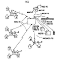
- FIG. 7 shows a universal mobile telecommunication system UM-TKS, in which the micro-cell-specific cordless telecommunication system MIZSL-TKS according to FIG. 3 uses a first network infrastructure NIS1 with the mobile telecommunication system MF-TKS and / or with the satellite radio telecommunication system SF-TKS Figure 2 is connected.
- An intercellular communication connection can thus be established via the network infrastructure NIS1.
- the network infrastructure NIS1 offers the possibility of establishing communication connections to wired switching systems (EWSD, private branch exchanges) via an air / line interface.
- EWSD wired switching systems
- FIG. 8 shows a modification of the universal mobile telecommunication system UM-TKS according to FIG. 7, which consists in that a second network infrastructure NIS2 is provided for the intercellular communication connection.
- This network infrastructure NIS2 differs from the first network infrastructure NIS1 according to FIG. 7 in that the micro-cell-specific transmission / reception arrangement MIZ-SEA is integrated in the network infrastructure.
- the network infrastructure NIS2 also offers the possibility of establishing communication connections to wired switching systems (EWSD, private branch exchanges) via an air / line interface.
- EWSD wired switching systems
- an intercellular communication connection can always be established via the network infrastructure NIS1 .
Description
- Die Erfindung betrifft ein universelles Mobil-Telekommunikationssystem gemäß dem Oberbegriff des Patentanspruches 1.
- Die moderne Mobilkommunikation, z. B. Mobil-Telekommunikation zur Übertragung von Sprache, Daten, Text, Grafik, Fest- und Bewegtbild, wird analog zu der stationären Kommunikation (z. B. ISDN-Kommunikationssystem; Integrated Services Digital Network) in einen privaten und öffentlichen Bereich unterteilt. Darüber hinaus unterscheidet man bei der Mobil-Telekommunikation (erste und zweite Generation) zwischen einer Zellular- und Schnurlos-Telekommunikation. Die Schnurlos-Telekommunikation stützt sich dabei bisher im wesentlichen auf Schnurlos-Telekommunikationssysteme für Heim- und Büroanwendungen, während die Zellular-Telekommunikation vorwiegend durch den Einsatz von Mobilfunk-Telekommunikationssystemen bestimmt wird.
- Für die vorstehend genannten Mobilkommunikationssysteme, insbesondere solche der zweiten Generation, wird überwiegend ein TDMA-Verfahren (Time Division Multiple Access) für den Zugriff und das Multiplexen der zu übertragenden Signale verwendet. Für zukünftige Mobil-Telekommunikationssysteme (z. B. dritte Generation) wird aber auch das CDMA-Übertragungsverfahren (Code Division Multiple Access) nicht zuletzt wegen des zu erwartenden Einsatzes von zellenorientierten Übermittlungsverfahren (ATM-Verfahren; Asynchronus Transfer Mode) an Bedeutung gewinnen. Dies liegt daran, daß für ein immer größeres Angebot von Kommunikations- und Informationsdiensten bei gleichzeitig steigenden Anforderungen an die Qualität und Menge der zu übertragenden Bitraten neben den Zugriffs- und Multiplexverfahren die optimierte Signalcodierung, Kanalcodierung für eine flexible Luftschnittstelle eine immer größere Rolle spielen wird.
- Das TDMA- als auch das CDMA-Übertragungsverfahren bilden dabei letztlich die Grundlage für die verschiedenen Systemstandards bei der mobilen Telekommunikation. Hinsichtlich des TDMA-Verfahrens sind die gegenwärtig auf dem Markt eingeführten Schnurlos-Telekommunikationssysteme unter anderem nach dem digitalen paneuropäischen DECT-Standard (Digital European Cordless Telecommunication) und dem digitalen CT2-Standard (Cordless Telephone 2) aufgebaut, während die Mobilfunk-Telekommunikationssysteme nach dem weltweiten GSM-Standard (Groupe Spéciale Mobile; Global System for Mobile Communications) aufgebaut sind.
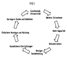
- Die Weiterentwicklung der Mobilkommunikation in einer Wirkungsspirale nach Figur 1 (Telcom Report 15; 1992; Heft 2, Seiten 57 bis 59) wird zu der bereits angesprochenen dritten Generation von Mobil-Telekommunikationssystemen führen, bei denen die bisherige Trennung zwischen Zellular- und Schnurlos-Telekommunikation aufgehoben ist. Diese dritte Generation der Mobil-Telekommunikation zeichnet sich durch eine universelle (zeitlich und örtlich) Mobilität aus, bei der jeder Kommunikationsteilnehmer überall und jederzeit erreichbar sein wird. Bei dieser universellen Mobilität unterscheidet man zwischen einer gerätebezogenen Mobilität über Luftanschlüsse und einer personenbezogenen Mobilität über Luft- und Kabelanschlüsse. Die Einbeziehung beider Aspekte in eine universelle Mobilkommunikation führt zu einer "Advanced Mobility" mit einem universellen mobilen Telekommunikationssystem (UMTS = Universal Mobile Telecommunication System) in Verbindung mit einer universellen persönlichen Telekommunikation (UPT = Universal Personal Telecommunication). Das universelle mobile Telekommunikationssystem (UMTS) benötigt dabei sowohl flexible Luftschnittstellen als auch eine intelligente Netzinfrastruktur. Durch eine solche Systemstruktur ist es gewährleistet, daß zum einen mobile Teilnehmer mit unterschiedlichen Geschwindigkeiten und Verkehrsdichten miteinander kommunizieren können und zum anderen eine Vielzahl von Telekommunikations- und Nachrichtendiensten (Informationsdiensten) mit hoher Qualität und Kapazität angeboten werden kann.
- In Figur 2 ist ausgehend von der Druckschrift Telcom Report 15; 1992; Heft 2, Seiten 60 bis 63 ein Szenario "Universelle Mobilkommunikation - Advanced Mobility" mit den verschiedenen Anwendungsfällen in bezug auf den Zellenradius dargestellt. Der Aufbau des universellen mobilen Telekommunikationssystems (UMTS) unterteilt sich danach für die Anwendungsbereiche (Büro, Heim, Stadt und Land) in unterschiedliche Kommunikationszellen. Diese Zellen können dabei zwei(Land, Stadt) oder dreidimensional (Gebäude) miteinander verknüpft sein. Nach der Darstellung in Figur 2 sind die verschiedenen Arten der mobilen Telekommunikation (Schnurlos-, Mobilfunk- und Satelliten-Telekommunikation SL-TK, MF-TK, S-TK) in Abhängigkeit des Zellenradius separat oder in einer Mischform dargestellt.
- Die Schnurlos-Telekommunikation SL-TK findet in ihrer reinen, separaten Form für Büro- und Heimanwendungen im Pikozellenbereich statt. In diesem Pikozellenbereich - mit einem Pikozellenradius PIZR von bis zu 200 m (Übertragungsreichweite) - ist mindestens eine Pikozelle PIZ mit einem Schnurlos-Telekommunikationssystem SL-TKS vorhanden. Das Schnurlos-Telekommunikationssystem SL-TKS besteht dabei aus einer pikozellenindividuellen Basistation PIZ-BS (Schnurlos-Basisstation) und mindestens einer der Basisstation PIZ-BS zugeordneten pikozellenindividuellen Mobilstation PIZ-MS (Schnurlos-Mobilstation). Wenn - wie vorstehend und im folgenden - Begriffe mit der Endung "zellenindividuell/e/en" im Zusammenhang mit einem Gegenstand/einer Tätigkeit/einer Eigenschaft verwendet werden, dann ist damit der Gegenstand/die Tätigkeit/die Eigenschaft gemeint, der/die einer Zelle (z. B. einer Piko-, Mikro-, Makro- und Hyperzelle) eigen ist bzw. zu einer Zelle gehört.
- Die Mobilfunk-Telekommunikation MF-TK findet in ihrer reinen, separaten Form für Stadt- bzw. Landanwendungen in stationären Gütern (z. B. Gebäuden) und/oder in dynamischen, beweglichen Gütern (z. B. Auto, Zug etc.) im Makrozellenbereich statt. In diesem Makrozellenbereich - mit einem Makrozellenradius MAZR von z. B. bis zu 20 km (Übertragungsreichweite) -, der den Pikozellenbereich mit der Pikozelle PIZ und einen Mikrozellenbereich mit mindestens einer Mikrozelle MIZ umfaßt, ist mindestens eine Makrozelle MAZ mit einem Mobilfunk-Telekommunikationssystem MF-TKS vorhanden. Dieses Mobilfunk-Telekommunikationssystem MF-TKS besteht dabei aus einer makrozellenindividuellen Basisstation MAZ-BS (Mobilfunk-Basisstation), die stationär oder mobil (z. B. Auto, Zug) aufgebaut sein kann, und mindestens einer der Basisstation MAZ-BS zugeordneten makrozellenindividuellen Mobilstation MAZ-MS (Mobilfunk-Mobilstation).
- Als Ergänzung zur Schnurlos- und Mobilfunk-Telekommunikation SL-TK, MF-TK findet die Satelliten-Telekommunikation SF-TK in einem Hyperzellenbereich statt. In diesen Hyperzellenbereich - mit einem Hyperzellenradius HYZR von mehreren hundert Kilometern (Übertragungsreichweite) - ist mindestens eine Hyperzelle HYZ mit einem Satelliten-Telekommunikationssystem SF-TKS vorhanden. Dieses Satelliten-Telekommunikationssystem SF-TKS beteht dabei aus einem z. B. auf der geostationären Erdumlaufbahn positionierten Satelliten SAT einer hyperzellenindividuellen Basisstation HYZ-BS, die stationär als Erdstation ES oder mobil als Mobil-Erdstation MES (z. B. im Flugzeug, Schiff, Lkw etc.) aufgebaut sein kann, und mindestens einer der Basistation HYZ-BS zugeordneten hyperzellenindividuellen Mobilstation HYZ-MS.
- Bei der Mischform aus den drei vorstehend genannten Arten der mobilen Telekommunikation wird beispielsweise für die Realisierung des "Advanced Mobility"-Konzeptes innerhalb des universellen mobilen Telekommunikationssystems (UMTS) eine Netzinfrastruktur NIS (ISDN = Integrated Services Digital Network, B-ISDN = Breitband-Integrated Services Digital Network) verwendet.
- Bei dieser Netzinfrastruktur NIS handelt es sich beispielsweise um ein Schmalband- oder Breitband-ISDN-Kommunikationssystem. In der Druckschrift Telcom Report 8; 1985; Sonderheft mit dem Titel "Diensteintegrierendes Digitalnetz ISDN" - Ganzes Dokument - ist ein Schmalband-ISDN-Kommunikationssystem und in den Druckschriften Telcom Report 14; 1991; Sonderheft mit dem Titel "Telcom 91" - Seiten 12 bis 19 ("Vision ONE - Optimierte Netz-Evolution") - sowie Telcom Report 14; 1991; - Seiten 36 bis 39 ("Grundsteine für schnelleren B-ISDN-Aufbau"), Seiten 40 bis 43 ("Breitband-ISDN ante portas"), Seiten 258 bis 261 ("Schrittmacher für bitratenvariable Breitbandkommunikation") - ein Breitband-ISDN-Kommunikationssystem beschrieben.
- Diese Netzinfrastruktur NIS ist mit den pikozellenindividuellen Basisstationen PIZ-BS des Schnurlos-Telekommunikationssystems SL-TKS, den makrozellenindividuellen Basisstationen MAZ-BS des Mobilfunk-Telekommunikationssystems MF-TKS und/oder über die stationäre Erdfunkstelle ES mit dem Satelliten SAT des Satelliten-Telekommunikationssystems SF-TKS bidirektional verbunden.
- Um ein solches in der Figur 2 dargestelltes und vorstehend beschriebenes universelles mobiles Telekommunikationssystem UMTS installieren zu können, müssen jedoch noch eine Reihe von Problemen gelöst werden.
- Diese Reihe von Problemen betrifft
- Einführungskonzepte (z. B. notwendige technische Kompatibilität bzw. Zusammenarbeit mit vorhandenen Systemen und Netzen im Hinblick auf eine Flächendeckung, Nutzungsumfang, mögliche Kommunikations- und Informationsdienste etc.);
- ein langfristiges Konzept mit harmonischer Integration oder komplexen "Interworking" in einem Multi-System- oder Multi-Betreiber-Szenario;
- mögliche Substitutionen (z. B. zwischen Leitungs- und Luftanschlüssen oder zwischen UPT und UMTS);
- Nutzen von Synergie-Effekten in Entwicklung und Fertigung;
- eine mögliche Verzögerung und Beeinflussung des universellen mobilen Telekommunikationssystems (UMTS) durch ständige Verbesserungen bei den Systemen der zweiten Generation (Advanced GSM, Advanced DECT);
- technische, rechtliche, politische, gesellschaftliche Unsicherheiten (z. B. Zusammenarbeit verteilter Datenbanken, künftige Frequenzzuordnung, mögliche Beeinträchtigung der Gesundheit durch Funk).
- Bei dieser Vielzahl von Problemen scheint eine evolutionäre Weiterentwicklung des universellen mobilen Telekommunikationssystems (UMTS) wahrscheinlich zu sein. Im Zuge dieser evolutionären Weiterentwicklung werden die zellulare interaktive Telekommunikation (Mobilfunk) und die schnurlose interaktive Telekommunikation (Schnurlos-Technologie) schrittweise bis hin zu einer universellen Mobilkommunikation (UMTS) mit "Advanced Mobility" vorangetrieben.
- Wenn im folgenden von einem universellen Mobil-Telekommunikationssystem gemäß der Darstellung in Figur 2 die Rede ist, so ist damit u. a. ein Telekommunikationssystem gemeint, das
- auf verschiedenen Zugriffs-, Multiplex-, Codier- und Modulationsverfahren (TDMA- und CDMA-Verfahren) basiert,
- sich auf den Einsatz des zellenorientierten Übermittlungsverfahrens (ATM = Asynchronous Transfer Mode) in der Netzinfrastruktur NIS stützt,
- für verschiedene Telekommunikations-Standards (DECT, GSM, Advanced DECT, Advanced GSM) anwendbar ist und
- für verschiedene Kommunikations- und Nachrichten/Informationsdienste (z. B. Sprachdialog, Informationsübertragung in Form von Daten, Text und Bild sowie Notruf-, Ortungs- und Navigationsdienste) brauchbar ist.
- Aus der EP 0 418 096 A2 ist ein zellulares Mobilfunksystem (Makrozelle) bekannt, das in mehrere Subzellen (Pikozellen) unterteilt ist. Jeder dieser Subzellen ist eine Duplex-Repeaterstation zugeordnet, durch die eine makrozellenindividuelle Funkverbindung zwischen einer makrozellenindividuellen Basisstation und einem den Subzellen jeweils zugeordneten Kleinleistungs-Mobilteil aufgebaut werden kann. Die Duplex-Repeaterstation hat dabei die Aufgabe, von den Kleinleistungs-Mobilteilen zu der makrozellenindividuellen Basisstation übertragene Funksignale zu empfangen, umzusetzen und zu verstärken sowie von der makrozellenindividuellen Basisstation an die Kleinleistungs-Mobilteile übertragene Funksignale zu empfangen, umzusetzen und zu bedämpfen (Aufgaben eines Transponders).
- Aus der dem Anmeldungsgegenstand am nächsten kommenden US-4,748,655 sind tragbare Telefone bekannt, die über eine Vielzahl von verschiedenen Netzkopplungseinrichtungen (Gateways), wie z. B. gemeinsame Funkeinheiten, Funktelefone, Schnurlostelefone oder private Nebenstellenanlagen, an ein zellulares Funknetzwerk angeschlossen werden können. Darüber hinaus kann das tragbare Telefon auch als Funkrufempfänger innerhalb des zellularen Funknetzwerkes verwendet werden. Der Benutzer eines solchen multifunktionalen Telefons kann somit, ohne ein für die Telekommunikation in dem zellularen Funknetzwerk erforderliches Funktelefon zu besitzen, an der Netzwerktelekommunikation teilnehmen. Diese Teilnahme wird dabei durch die verschiedenen Netzkopplungseinrichtungen sichergestellt. Von den verschiedenen Netzkopplungseinrichtungen ist insbesondere die als Mehrkanalanordnung ausgebildete gemeinsame Funkeinheit in der Lage, eine Vielzahl der genannten multifunktionalen Telefone innerhalb eines gegenüber den Zellen des Funknetzwerkes kleineren, begrenzten Bereiches zu bedienen. Die vorzugsweise transportabel ausgebildete und z. B. in öffentlichen Bereichen wie Bahnhöfen, Flughäfen, Zügen oder Bussen eingesetzte gemeinsame Funkeinheit dient zu den genannten Telekommunikationszwecken ausschließlich als Verbindungs- und Umsetzungseinheit zwischen einer dem zellularen Funknetzwerk zugeordneten Basisstation und den multifunktionalen Telefonen. Die Wirkungsweise der gemeinsamen Funkeinheit entspricht somit einem Transponder, wie er beispielsweise aus der Satellitentechnik bekannt ist.
- Aus der US-4,759,051 ist ein zellulares Funktelefonsystem bekannt, bei dem ein geografischer Funkbereich mit einer zentralen Zellenstation in mehrere Funkzellen unterteilt ist. Jede dieser Funkzellen enthält einen Transponder, wobei der Transponder auf der Funkstrecke zwischen tragbaren Funkeinheiten und der Zellstation die zu übetragenden Funksignale aufnimmt, verstärkt und wieder abgibt.
- In der IEEE Communications Magazine 30, Dez. 1992, No. 12, Seiten 54 bis 62 werden Konzeption und Voraussetzungen eines universellen Mobil-Telekommunikationssystems (UMTS) für die dritte System-Generation der mobilen Telekommunikation erläutert.
- Die der Erfindung zugrundeliegende Aufgabe besteht darin, ein universelles Mobil-Telekommunikationssystem anzugeben, bei dem im Zuge der Weiterentwicklung der mobilen Telekommunikation gemäß der Wirkungsspirale nach Figur 1 ein pikozellenindividuelles Schnurlos-Telekommunikationssystem auf Kommunikationszellen mit unterschiedlichen Zellenradien (universell) erweitert werden kann.
- Diese Aufgabe wird ausgehend von dem in dem Oberbegriff des Patentanspruches 1 definierten universellen mobilen Telekommunikationssystem durch die in dem kennzeichnenden Teil des Patentanspruches 1 angegebenen Merkmale gelöst.
- Der wesentliche Vorteil des erfindungsgemäßen universellen Mobil-Telekommunikationssystems liegt darin, daß ein auf Kommunikationszellen mit unterschiedlichen Zellenradien erweitertes Schnurlos-Telekommunikationssystem in dem erweiterten Schnurlosbereich mit einer geringeren Sendeleistung für Schnurlos-Mobilstationen auskommt und dadurch die Belastung eines Benutzers der Schnurlos-Mobilstation durch elektromagnetische Wellen bei der Schnurlosübertragung herabgesetzt wird. Ein weiterer wesentlicher Vorteil des erfindungsgemäßen universellen Mobil-Telekommunikationssystems besteht darin, daß durch das erweiterte Schnurlos-Telekommunikationssystem, insbesondere im Pikozellen- und Mikrozellenbereich, die Möglichkeit für Fernsprechen mit höherer Qualität bis hin zum Bildfernsprechen gegeben ist. Dies liegt daran, daß je geringer der Zellenradius einer Kommunikationszelle ist, desto größer ist im allgemeinen die je Flächeneinheit verfügbare Kapazität und damit die nutzbare Bitrate für die jeweilige Anwendung. Das erfindungsgemäße universelle Mobil-Telekommunikationssystem bietet somit im Zuge der Wirkungsspirale für eine universelle Mobil-Telekommunikation mit einer Advanced-Mobility bereits eine einfache Möglichkeit an, zellulare und schnurlose Mobil-Telekommunikationssysteme miteinander zu verbinden. Durch diese Verbindung zwischen den beiden Mobil-Telekommunikationssystemen und der dazu parallelen Entwicklung eines Breitband-ISDN-Kommunikationssystems kann somit ein universelles Mobil-Telekommunikationssystem aufgebaut werden, bei dem ein Telekommunikationsteilnehmer seinen Kommunikationspartner überall erreichen kann (Advanced-Mobility).
- Vorteilhafte Weiterbildungen der Erfindung sind in den Unteransprüchen angegeben.
- Ein Ausführungsbeispiel der Erfindung wird anhand der Figuren 3 bis 8 erläutert. Es zeigen:
- Figur 3 ein auf den Mikrozellenbereich erweitertes Schnurlos-Telekommunikationssystem,
- Figur 4 und 5 ein auf den Makrozellenbereich erweitertes Schnurlos-Telekommunikationssystem,
- Figur 6 ein auf den Hyperzellenbereich erweitertes Schnurlos-Telekommunikationssystem,
- Figur 7 und 8 ein universelles Mobil-Telekommunikationssystem.
- Figur 3 zeigt ein auf eine Mikrozelle MIZ des Mikrozellenbereiches nach Figur 2 erweitertes Schnurlos-Telekommunikationssystem MIZSL-TKS. Die Mikrozelle MIZ ist dabei ein Kommunikationsraum, in dessen Kommunikationszentrum - im Fall der Mikrozelle MIZ - eine mikrozellenindividuelle Sende/Empfangsanordnung MIZ-SEA angeordnet ist. Über diese Sende/Empfangsanordnung MIZ-SEA wird die gesamte mikrozellenindividuelle Schnurlos-Telekommunikation MIZSL-TK abgewickelt. Die Sende-/Empfangsanordnung MIZ-SEA ist dabei z. B. als mikrozellenindividuelle Basisstation MIZ-BS ausgebildet. Für diese erweiterte mikrozellenindividuelle Schnurlos-Telekommunikation MIZSL-TK ist der Sende-/Empfangsanordnung MIZ-SEA mindestens eine Pikozelle PIZ für eine pikozellenindividuelle Schnurlos-Telekommunikation SL-TK nach Figur 2 über jeweils eine mikrozellenindividuelle Schnurlos-Verbindung MIZ-SLV zugeordnet. Die Anzahl der Pikozellen PIZ, die der Sende-/Empfangsanordnung MIZ-SEA über die entsprechende Anzahl der Schnurlos-Verbindungen MIZ-SLV zugeordnet sind, richtet sich insbesondere danach, wie groß die Kommunikationsteilnehmerdichte (Verkehrsdichte) in der Mikrozelle MIZ ist. Bei dünn besiedelten Regionen (Mikrozellen) ist die Anzahl der Pikozellen PIZ eher klein, während bei stark besiedelten Regionen (Mikrozellen) die Anzahl der Pikozellen PIZ mit den dazugehörigen mikrozellenindividuellen Schnurlosverbindungen MIZ-SLV groß ist. Die Anzahl der Pikozellen PIZ ist aber nicht nur von der Kommunikationsteilnehmerdichte abhängig, sondern orientiert sich auch an der in der Sende/Empfangsanordnung MIZ-SEA verfügbaren Übertragungskapazität. Diese Übertragungskapazität wird dabei im wesentlichen durch die Anzahl der Übertragungskanäle bestimmt. So stehen beispielsweise für nach dem DECT-Standard aufgebaute piko- bzw. mikrozellenindividuellen Schnurlos-Telekommunikationssysteme PIZSL-TKS, MIZSL-TKS gegenwärtig maximal zwölf Übertragungskanäle (Halb-Duplex-Übertragungskanäle) zur Verfügung. Für ein auf dem DECT-Standard basierendes mikrozellenindividuelles Schnurlos-Telekommunikationssystem MIZLS-TKS bedeutet dies, daß selbst bei einer großen Kommunikationsteilnehmerdichte in der Mikrozelle MIZ theoretisch nur m mit m = 12 Pikozellen PIZ enthalten sein können. Die Anzahl m ist deshalb theoretisch, weil innerhalb jeder Pikozelle PIZ wiederum die pikozellenindividuelle Schnurlos-Telekommunikation PIZSL-TK stattfindet. Findet diese pikozellenindividuelle Schnurlos-Telekommunikation PIZSL-TK ebenfalls nach dem DECT-Standard statt, so wird sich die Anzahl m mit m = 12 (wie in der Beschreibung des Ausführungsbeispiels später erläutert wird) entsprechend verringern. In dem in der Figur 3 dargestellten mikrozellenindividuellen Schnurlos-Telekommunikationssystem MIZSL-TKS sind beispielsweise m = 4 Pikozellen PIZ (PIZ1...PIZ4) über vier mikrozellenindividuelle Schnurlosverbindungen MIZ-SLV (MIZ-SLV1...MIZ-SLV4) der Sende-/Empfangsanordnung MIZ-SEA zugeordnet. Der maximale Abstand, mit dem diese Pikozellen PIZ1...PIZ4 von der Sende/Empfangsanordnung MIZ-SEA entfernt sein können, bestimmt sich nach dem Mikrozellenradius MIZR, der der Mikrozelle MIZ per Definition zugeordnet wird. Dieser Mikrozellenradius MIZR liegt beispielsweise bei 2000 m. So sind in Figur 3 die Pikozelle PIZ1 über die mikrozellenindividuelle Schnurlos-verbindung MIZ-SLV1 mit einem Mikrozellenradius MIZR1 von z. B. 1200 m, die Pikozelle PIZ2 über die mikrozellenindividuelle Schnurlosverbindung MIZ-SLV2 mit einem Mikrozellenradius MIZR2 von z. B. ebenfalls 1200 m, die Pikozelle PIZ3 über die mikrozellenindividuelle Schnurlosverbindung MIZ-SLV3 mit einem Mikrozellenradius MIZR3 von z. B. 1800 m und die Pikozelle PIZ 4 über die mikrozellenindividuelle Schnurlosverbindung MIZ-SLV4 mit einem Mikrozellenradius MIZR4 von z. B. 1000 m der Sende-/Empfangsanordnung MIZ-SEA zugeordnet. Die Pikozellen PIZ1...PIZ4 sind bis auf die Tatsache, daß sie von der Sende-/Empfangsanordnung MIZ-SEA unterschiedlich entfernt sein können, ansonsten in bezug auf die pikozellenindividuelle Schnurlos-Telekommunikation PIZSL-TK gleich strukturiert. In jeder Pikozelle PIZ ist für die pikozellenindividuelle Schnurlos-Telekommunikation PIZSL-TK im Kommunikationszentrum der Pikozelle PIZ eine Relaisstation RS angeordnet. Die Relaisstation RS weist für die mikrozellenindividuelle Schnurlos-Telekommunikation MIZSL-TK und die pikozellenindividuelle Schnurlos-Telekommunikation PIZSL-TK mehrere Antennen, eine erste Antenne ANT1 für die mikrozellenindividuelle Schnurlos-Telekommunikation MIZSL-TK und beispielsweise zwei zweite Antennen ANT2, ANT3 für die pikozellenindividuelle Schnurlos-Telekommunikation PIZSL-TK, auf. Während die erste Antenne ANT1 für die größere Übertragungsreichweite bei der mikrozellenindividuellen Schnurlos-Telekommunikation MIZSL-TK vorzugsweise als Richtantenne ausgebildet ist, sind die beiden zweiten Antennen ANT2, ANT3 für die pikozellenindividuelle Schnurlos-Telekommunikation PIZSL-TK vorzugsweise als Diversity-Antennen ausgebildet. Bezüglich der beiden Diversity-Antennen ANT2, ANT3 ist die Relaisstation RS entsprechend der in der nachveröffentlichten internationalen Patentanmeldung WO 94/10764 offenbarten technischen Lehre ausgebildet. Über diese Diversity-Antennen ANT2, ANT3 ist die Relaisstation RS mit mindestens einer pikozellenindividuellen Mobilstation PIZ-MS verbunden. Die Verbindung wird dabei für jede Mobilstation PIZ-MS über eine pikozellenindividuelle Schnurlosverbindung PIZ-SLV hergestellt. In dem in der Figur 3 dargestellten erweiterten Schnurlos-Telekommunikationssystem MIZSL-TKS sind in jeder Pikozelle PIZ jeweils n = 4 pikozellenindividuelle Mobilstationen PIZ-MS vorhanden. Für die Anzahl n der Mobilstationen PIZ-MS in Verbindung mit der die pikozellenindividuelle Schnurlos-Telekommunikation PIZSL-TK abwickelnden Relaisstation RS gelten dieselben Bedingungen und Voraussetzungen wie bei der mikrozellenindividuellen Schnurlos-Telekommunikation MIZSL-TK mit der Anzahl m von Pikozellen PIZ in Verbindung mit der die mikrozellenindividuelle Schnurlos-Telekommunikation MIZSL-TK abwickelnden Sende-/Empfangsanordnung MIZ-SEA. Ist demzufolge das pikozellenindividuelle Schnurlos-Telekommunikationssystem PIZSL-TKS wie das mikrozellenindividuelle Schnurlos-Telekommunikationssystem MIZSL-TKS nach dem DECT-Standard aufgebaut, so gilt für die Relaisstation RS, daß diese bezogen auf die zur Verfügung stehende Übertragungskapazität (Anzahl der Übertragungskanäle) insgesamt maximal m + n = 12 pikozellenindividuelle Schnurlos-Telekommunikationsverbindungen zu den umliegenden Mobilstationen PIZ-MS und mikrozellenindividuelle Schnurlos-Telekommunikationsverbindungen zur mikrozellenindividuellen Sende-/Empfangsanordnung MIZ-SEA aufbauen kann. Die für die Relaisstation RS geltende Bedingung m + n = 12 ergibt sich daraus, daß die Relaisstation RS für die mikrozellenindividuelle Schnurlos-Telekommunikation MIZSL-TK als mikrozellenindividuelle Mobilstation MIZ-MS und für die pikozellenindividuelle Schnurlos-Telekommunikation PIZSL-TK als pikozellenindividuelle Basisstation PIZ-BS ausgebildet ist. Die Relaisstation RS muß dabei für die Ausbildung als mikrozellenindividuelle Mobilstation MIZ-MS bei der mikrozellenindividuellen Schnurlos-Telekommunikation MIZSL-TK entsprechend (z. B. bezüglich Sendeleistung, Sendeantenne etc.) ausgelegt sein, um Nachrichten, Informationen bei dem Mikrozellenradius MIZR von bis 2000 m übertragen zu können.
- Die Figuren 4 bis 8 zeigen ausgehend von dem in der Figur 3 dargestellten mikrozellenindividuellen Schnurlos-Telekommunikationssystem MIZSL-TKS ein auf mindestens eine Makrozelle MAZ des Makrozellenbereiches nach Figur 2 (Figur 4 und 5), auf mindestens eine Hyperzelle HYZ des Hyperzellenbereiches nach Figur 2 (Figur 6) erweitertes Schnurlos-Telekommunikationssystem sowie zwei universell erweiterbare Schnurlos-Telekommunikationssysteme (Figur 7 und 8).
- So ist in der Figur 4 ein makrozellenindividuelles Schnurlos-Telekommunikationssystem MAZSL-TKS dargestellt, bei dem innerhalb einer Makrozelle MAZ des Makrozellenbereiches nach Figur 2 mit Mikrozellen MIZ1...MIZi eine Anzahl i des mikrozellenindividuellen Schnurlos-Telekommunikationssystems MIZSL-TKS nach Figur 3 zur Realisierung einer "Roaming- und/oder Hand Over"-Funktion angeordnet ist. Entsprechend der Anzahl i der mikrozellenindividuellen Schnurlos-Telekommunikationssysteme MIZSL-TKS1...MIZSL-TKSi gibt es in der Makrozelle MAZ eine Anzahl i von mikrozellenindividuellen Sende-/Empfangsanordnungen MIZ-SEA1...MIZ-SEAi, die wiederum z. B. als mikroindividuelle Basisstationen MIZ-BS1...MIZBSi ausgebildet sind und dabei entsprechend dem mikrozellenindividuellen Schnurlos-Telekommunikationssystem MIZSL-TKS nach Figur 3 die mikrozellenindividuelle Schnurlos-Telekommunikation MIZSL-TK mit der jeweiligen Pikozelle PIZ abwickeln. Einer ersten mikrozellenindividuellen Basisstation MIZ-BS1 sind dabei z. B. m = 4 Pikozellen PIZ mit jeweils einer Relaisstation RS und n = 4 pikozellenindividuellen Mobilstationen PIZ-MS zugeordnet, während einer i-ten mikrozellenindividuellen Basisstation MIZ-BSi z. B. m = 3 Pikozellen mit jeweils einer Relaisstation RS und n = 4 pikozellenindividuellen Mobilstationen PIZ-MS zugeordnet sind.
- In Figur 5 ist in Abwandlung zu dem makrozellenindividuellen Schnurlos-Telekommunikationssystem MAZSL-TKS nach Figur 4 statt der mikrozellenindividuellen Schnurlos-Telekommunikationssysteme MIZSL-TKS1...MIZSL-TKSi mit den mikrozellenindividuellen Sende-/Empfangsanordnungen MIZ-SEA1...MIZ-SEAi mindetens eine makrozellenindividuelle Sende/Empfangsanordnung MAZ-SEA für die erweiterte Schnurlos-Telekommunikation zuständig. Diese erweiterte Schnurlos-Telekommunikation kann dabei aus der mikrozellenindividuellen Schnurlos-Telekommunikation MIZSL-TK nach Figur 3 oder 4 und einer makrozellenindividuellen Mobilfunk-Telekommunikation MAZMF-TK (gemischtzellenindividuelle Telekommunikation nach Figur 5) oder aber aus einer makrozellenindividuellen Schnurlos-Telekommunikation MAZSL-TK und der makrozellenindividuellen Mobilfunk-Telekommunikation MAZMF-TK (einheitszellenindividuelle Telekommunikation) bestehen. Bei dieser einheitszellenindividuellen Telekommunikation muß die Relaisstation RS nach Figur 3 für die makrozellenindividuelle Schnurlos-Telekommunikation MAZSL-TK entsprechend (z. B. in bezug auf die Sendeleistung, Sendeantenne etc.) ausgelegt sein, um bei der makrozellenindividuellen Schnurlos-Telekommunikation MAZSL-TK als makrozellenindividuelle Mobilstation MAZ-MS dienen zu können.
- Die makrozellenindividuelle Sende-/Empfangsanordnung MAZ-SEA übernimmt dabei die Funktion einer makrozellenindividuellen Basisstation MAZ-BS und ist dabei vorzugsweise als Mobilfunk-Basisstation ausgebildet. Während die mikrozellenindividuelle Schnurlos-Telekommunikation MIZSL-TK bei der gemischtzellenindividuellen Telekommunikation analog zu der in dem mikrozellenindividuellen Schnurlos-Telekommunikationssystem MIZSL-TKS nach Figur 3 und 4 abläuft, dient die Sende/Empfangsanordnung MAZ-SEA bei der makrozellenindividuellen Mobilfunk-Telekommunikation MAZMF-TK (gemischt- und einheitszellenindividuelle Telekommunikation) als stationäre makrozellenindividuelle Basisstation SMAZ-BS, die über makrozellenindividuelle Mobilfunkverbindungen MAZ-MFV unmittelbar mit makrozellenindividuellen Mobilstationen MAZ-MS oder mittelbar über mobile makrozellenindividuelle Basisstationen MMAZ-BS mit den Mobilstationen MAZ-MS verbunden ist.
- Analog zur Darstellung in der Figur 4 können bei dem makrozellenindividuellen Schnurlos-Telekommunikationssystem MAZSL-TKS nach Figur 5 wiederum mehrere Makrozellen MAZ mit jeweils einer makrozellenindividuellen Sende/Empfangsanordnung MAZ-SEA zur Realisierung der "Roaming- und/oder Hand Over"-Funktion vorgesehen sein.
- In Figur 6 ist ein hyperzellenindividuelles Schnurlos-Telekommunikationssystem HYZSL-TKS dargestellt, bei dem in einer Hyperzelle HYZ des Hyperzellenbereiches nach Figur 2 eine hyperzellenindividuelle Sende-/Empfangsanordnung HYZ-SA für die erweiterte Schnurlos-Telekommunikation angeordnet ist. Diese erweiterte Schnurlos-Telekommunikation kann dabei aus der mikrozellenindividuellen Schnurlos-Telekommunikation MIZSL-TK nach Figur 3 oder 4 und einer hyperzellenindividuellen Satellitenfunk-Telekommunikation HYZSF-TK (gemischtzellenindividuelle Telekommunikation nach Figur 6) oder aber aus einer hyperzellenindividuellen Schnurlos-Telekommunikation HYZSL-TK und der hyperzellenindividuellen Satellitenfunk-Telekommunikation HYZSF-TK (einheitszellenindividuelle Telekommunikation) bestehen. Bei dieser einheitszellenindividuellen Telekommunikation muß für die hyperzellenindividuelle Schnurlos-Telekommunikation HYZSL-TK die Relaisstation RS für die Übertragungsreichweiten im Hyperzellenbereich mit dem Hyperzellenradius HYZR von mehreren 100 km entsprechend (z. B. bezüglich der Sendeleistung, Sendeantenne etc.) ausgelegt sein, um bei der hyperzellenindividuellen Schnurlos-Telekommunikation HYZSL-TK als hyperzellenindividuelle Mobilstation HYZ-MS dienen zu können.
- Die hyperzellenindividuelle Sende-/Empfangsanordnung HYZ-SEA übernimmt dabei für die gemischt- und einheitszellenindividuelle Telekommunikation die Funktion einer hyperzellenindividuellen Basisstation HYZ-BS und ist dabei vorzugsweise als Erdstation ES ausgebildet. Während die mikrozellenindividuelle Schnurlos-Telekommunikation MIZSL-TK bei der gemischtzellenindividuellen Telekommunikation analog zu der in dem mikrozellenindividuellen Schnurlos-Telekommunikationssystem MIZSL-TKS nach Figur 3 und 4 abläuft, dient die Sende/Empfangsanordnung HYZ-SEA bei der hyperzellenindividuellen Satellitenfunk-Telekommunikation HYZSF-TK (gemischt- und einheitszellenindividuelle Telekommunikation) als stationäre hyperzellenindividuelle Basisstation SHYZ-BS, die über hyperzellenindividuelle Satellitenfunkverbindungen HYZ-SFV und einen auf der geostationären Erdumlaufbahn angeordneten Satelliten SAT mittelbar über mobile hyperzellenindividuelle Basisstationen MHYZ-BS mit hyperzellenindividuellen Mobilstationen HYZ-MS verbunden ist.
- Analog zu der Darstellung in der Figur 4 können bei dem hyperzellenindividuellen Schnurlos-Telekommunikationssystem HYZSL-TKS nach Figur 6 wiederum mehrere Hyperzellen HYZ mit jeweils einer hyperzellenindividuellen Sende/Empfangsanordnung HYZ-SEA zur Realisierung der "Roaming- und/oder Hand Over"-Funktion vorgesehen sein.
- Figur 7 zeigt ein universelles Mobil-Telekommunikationssystem UM-TKS, bei dem das mikrozellenindividuelle Schnurlos-Telekommunikationssystem MIZSL-TKS nach Figur 3 über eine erste Netzinfrastruktur NIS1 mit dem Mobilfunk-Telekommunikationssystem MF-TKS und/oder mit dem Satellitenfunk-Telekommunikationssystem SF-TKS nach Figur 2 verbunden ist. Über die Netzinfrastruktur NIS1 kann somit eine interzellulare Kommunikationsverbindung aufgebaut werden. Darüber hinaus bietet die Netzinfrastruktur NIS1 die Möglichkeit, über eine Luft-/Leitungsschnittstelle Kommunikationsverbindungen zu leitungsgebundenen Vermittlungsanlagen (EWSD, Nebenstellenanlagen) aufzubauen. Außerdem besteht die Möglichkeit, nicht nur das mikrozellenindividuelle Schnurlos-Telekommunikationssystem MIZSL-TKS nach Figur 3 an die Netzinfrastruktur NIS1 anzuschließen, sondern auch die übrigen erweiterten Schnurlos-Telekommunikationssysteme nach Figur 4 bis 6. In all den genannten Ausführungsformen des universellen Mobil-Telekommunikationssystems UM-TKS kann über die Netzinfrastruktur NIS1 immer eine interzellulare Kommunikationsverbindung aufgebaut werden.
- Figur 8 zeigt eine Modifikation des universellen Mobil-Telekommunikationssystems UM-TKS nach Figur 7, die darin besteht, daß für die interzellulare Kommunikationsverbindung eine zweite Netzinfrastruktur NIS2 vorgesehen ist. Diese Netzinfrastruktur NIS2 unterscheidet sich von der ersten Netzinfrastruktur NIS1 nach Figur 7 dadurch, daß die mikrozellenindividuelle Sende-/Empfangsanordnung MIZ-SEA in der Netzinfrastruktur integriert ist. Die Netzinfrastruktur NIS2 bietet darüber hinaus die Möglichkeit, über eine Luft/Leitungsschnittstelle Kommunikationsverbindungen zu leitungsgebundenen Vermittlungsanlagen (EWSD, Nebenstellenanlagen) aufzubauen. Außerdem besteht die Möglichkeit, nicht nur das mikrozellenindividuelle Schnurlos-Telekommunikationssystem MIZSL-TKS nach Figur 3 an die Netzinfrastruktur NIS1 anzuschließen, sondern auch die übrigen erweiterten Schnurlos-Telekommunikationssysteme nach Figur 4 bis 6. In all den genannten Ausführungsformen des universellen Mobil-Telekommunikationssystems UM-TKS kann über die Netzinfrastruktur NIS1 immer eine interzellulare Kommunikationsverbindung aufgebaut werden.
Claims (14)
- Universelles Mobil-Telekommunikationssystem(a) mit einem erweiterten Schnurlos-Telekommunikationssystem (MIZSL-TKS, MAZSL-TKS, HYZSL-TKS), das(a1) einen Pikozellenbereich mit mindestens einer Pikozelle (PIZ) und(a2) einen dem Pikozellenbereich übergeordneten Zellenbereich mit mindestens einer der Pikozelle (PIZ) übergeordneten Zelle (MIZ, MAZ, HYZ) abdeckt,(b) mit einer der Pikozelle (PIZ) zugeordneten Pikozellen-Mobilstation (PIZ-MS), die mit einer in der Pikozelle (PIZ) enthaltenen Relaisstation (RS) durch Telekommunikation verbindbar ist, wobei(b1) die Relaisstation (RS) mit einer in der übergeordneten Zelle (MIZ, MAZ, HYZ) enthaltenen Sende/Empfangsanordnung (MIZ-SEA, MIZ-SEA1...MIZ-SEAi, MAZ-SEA, HYZ-SEA, NIS2) durch Telekommunikation verbindbar ist,dadurch gekennzeichnet, daß
(c) der Relaisstation (RS) neben der Funktion der Telekommunikationsverbindung zu der der übergeordneten Zelle (MIZ, MAZ, HYZ) zugeordneten Sende-/Empfangsanordnung (MIZ-SEA, MIZ-SEA1...MIZ-SEAi, MAZ-SEA, HYZ-SEA, NIS2) im Sinne der Bildung eines die Pikozellen-Mobilstation (PIZ-MS) einschließenden, die Pikozelle (PIZ) abdeckenden Schnurlos-Telekommunikationssystems (PIZSL-TKS) auch die Funktion einer Pikozellen-Basisstation (PIZ-BS) zugewiesen ist. - Universelles Mobil-Telekommunikationssystem nach Anspruch 1, dadurch gekennzeichnet, daß die Relaisstation (RS) mindestens eine erste Sende-/Empfangsantenne (ANT1) für die Telekommunikationsverbindung zu der der übergeordneten Zelle (MIZ, MAZ, HYZ) zugeordneten Sende-/Empfangsanordnung (MIZ-SEA, MIZ-SEA1...MIZ-SEAi, MAZ-SEA, HYZ-SEA, NIS2) und mindestens eine zweite Sende-/Empfangsantenne (ANT2, ANT3) für die Telekommunikationsverbindung zu der Pikozellen-Mobilstation (PIZ-MS) aufweist.
- Universelles Mobil-Telekommunikationssystem nach Anspruch 2, dadurch gekennzeichnet, daß die erste Sende-/Empfangsantenne (ANT1) als Richtantenne ausgebildet ist.
- Universelles Mobil-Telekommunikationssystem nach Anspruch 2 oder 3, dadurch gekennzeichnet, daß zwei zweite Sende/Empfangsantennen (ANT2, ANT3) vorgesehen sind, die als Diversity-Antennen ausgebildet sind.
- Universelles Mobil-Telekommunikationssystem nach einem der Ansprüche 1 bis 4, dadurch gekennzeichnet, daß eine erste Sende-/Empfangsanordnung (MIZ-SEA, MIZ-SEA1...MIZ-SEAi) als eine einer Mikrozelle (MIZ) zugeordnete Schnurlos-Basisstation (MIZ-BS) ausgebildet ist.
- Universelles Mobil-Telekommunikationssystem nach einem der Ansprüche 1 bis 4, dadurch gekennzeichnet, daß eine zweite Sende-/Empfangsanordnung (MAZ-SEA) als eine einer Makrozelle (MAZ) zugeordnete Mobilfunk-Basisstation ausgebildet ist.
- Universelles Mobil-Telekommunikationssystem nach Anspruch 5, dadurch gekennzeichnet, daß die erste Sende/Empfangsanordnung (MIZ-SEA, MIZ-SEA1...MIZ-SEAi) mit einer ersten Vermittlungsanlage (NIS1) verbunden ist.
- Universelles Mobil-Telekommunikationssystem nach Anspruch 6, dadurch gekennzeichnet, daß die zweite Sende-/Empfangsanordnung (MAZ-SEA) mit einer ersten Vermittlungsanlage (NSI1) verbunden ist.
- Universelles Mobil-Telekommunikationssystem nach einem der Ansprüche 1 bis 4, dadurch gekennzeichnet, daß eine dritte Sende-/Empfangsanordnung (NIS2) als eine zweite Vermittlungsanlage (NIS2) mit einer Luft-/Leitungsschnittstelle ausgebildet ist.
- Universelles Mobil-Telekommunikationssystem nach einem der Ansprüche 7 bis 9, dadurch gekennzeichnet, daß die Vermittlungsanlage (NIS1, NIS2) als Nebenstellenanlage ausgebildet ist.
- Universelles Mobil-Telekommunikationssystem nach einem der Ansprüche 1 bis 4, dadurch gekennzeichnet, daß eine vierte Sende-/Empfangsanordnung (HYZ-SEA) als Satellitenfunk-Telekommunikationssystem (SF-TKS) mit einem auf einer geostationären Erdumlaufbahn angeordneten Satelliten (SAT) und einer Erdfunkstation (HYZ-BS, MES, ES) ausgebildet ist.
- Universelles Mobil-Telekommunikationssystem nach einem der Ansprüche 1 bis 11, dadurch gekennzeichnet, daß das Schnurlos-Telekommunikationssystem (PIZSL-TKS) und ein erstes erweitertes Schnurlos-Telekommunikationssystem (MIZSL-TKS) als DECT-System aufgebaut sind.
- Universelles Mobil-Telekommunikationssystem nach einem der Ansprüche 1 bis 11, dadurch gekennzeichnet, daß das Schnurlos-Telekommunikationssystem (PIZSL-TKS) als DECT-System und ein zweites erweitertes Schnurlos-Telekommunikationssystem (MAZSL-TKS) als Schnurlos/Mobilfunk-System aufgebaut ist.
- Universelles Mobil-Telekommunikationssystem nach einem der Ansprüche 1 bis 13, dadurch gekennzeichnet, daß das Schnurlos-Telekommunikationssystem (PIZSL-TKS) und das erweiterte Schnurlos-Telekommunikationssystem (MIZSL-TKS, MAZSL-TKS, HYZSL-TKS) als Bildtelefonie-System aufgebaut sind.
Applications Claiming Priority (3)
| Application Number | Priority Date | Filing Date | Title |
|---|---|---|---|
| DE4326523A DE4326523A1 (de) | 1993-08-06 | 1993-08-06 | Universelles Mobil-Telekommunikationssystem |
| DE4326523 | 1993-08-06 | ||
| PCT/DE1994/000910 WO1995005040A1 (de) | 1993-08-06 | 1994-08-05 | Universelles mobil-telekommunikationssystem |
Publications (2)
| Publication Number | Publication Date |
|---|---|
| EP0712551A1 EP0712551A1 (de) | 1996-05-22 |
| EP0712551B1 true EP0712551B1 (de) | 1997-10-22 |
Family
ID=6494650
Family Applications (1)
| Application Number | Title | Priority Date | Filing Date |
|---|---|---|---|
| EP94922844A Expired - Lifetime EP0712551B1 (de) | 1993-08-06 | 1994-08-05 | Universelles mobil-telekommunikationssystem |
Country Status (11)
| Country | Link |
|---|---|
| US (1) | US6535731B1 (de) |
| EP (1) | EP0712551B1 (de) |
| JP (1) | JP3382945B2 (de) |
| CN (1) | CN1084984C (de) |
| AT (1) | ATE159632T1 (de) |
| AU (1) | AU676932B2 (de) |
| CA (1) | CA2168734A1 (de) |
| DE (2) | DE4326523A1 (de) |
| ES (1) | ES2108476T3 (de) |
| FI (1) | FI960518A (de) |
| WO (1) | WO1995005040A1 (de) |
Cited By (1)
| Publication number | Priority date | Publication date | Assignee | Title |
|---|---|---|---|---|
| DE19843476A1 (de) * | 1998-09-22 | 2000-04-27 | Siemens Ag | Verfahren zur Funkversorgung eines Mobil-Terminals eines Mobilfunknetzes |
Families Citing this family (41)
| Publication number | Priority date | Publication date | Assignee | Title |
|---|---|---|---|---|
| DE19502641C2 (de) * | 1995-01-20 | 1999-01-14 | Deutsche Telephonwerk Kabel | Anordnung zur Netzabschlußtechnik für öffentliche, stationäre Telekommunikationsnetze |
| DE19520024A1 (de) * | 1995-05-31 | 1996-12-05 | Siemens Ag | Universelles Mobil-Telekommunikationssystem |
| DE19535329C2 (de) * | 1995-09-22 | 2002-02-28 | Bernhard Walke | Verfahren zum Übertragen von ATM-Zellen im Zeitmultiplex in einem Mobilfunksystem |
| DE19543280C2 (de) * | 1995-11-20 | 2001-05-03 | Bernhard Walke | Kommunikationssystem zum Übertragen von ATM-Zellen mit Hilfe von Datenblöcken über ein drahtloses Medium |
| DE19548044C2 (de) | 1995-12-21 | 1998-03-26 | Siemens Ag | Verfahren und Anordnung zum Erzeugen von Zufallszahlen in Telekommunikationsgeräten eines drahtlosen Telekommunikationssystems |
| DE29622893U1 (de) * | 1996-01-03 | 1997-09-04 | Hoseit Winrich P A | Über ein digitales Funknetz betriebene Kommunikationsgeräte sowie das Funknetz für diese Geräte |
| DE19608183A1 (de) | 1996-03-04 | 1997-09-18 | Siemens Ag | Verfahren und Anordnung zum Verbessern des Ausnutzungsgrades von Telekommunikationskanälen in örtlich konzentrierten, asynchronen, drahtlosen Telekommunikatonssystemen |
| DE19609634A1 (de) * | 1996-03-12 | 1997-09-18 | Siemens Ag | Schaltregler |
| DE19609883C1 (de) | 1996-03-13 | 1997-10-09 | Siemens Ag | Verfahren und Anordnung zum Übertragen von systemspezifischen Daten in einem synchronen Mikroprozessorsystem |
| DE19610086C2 (de) * | 1996-03-14 | 2000-02-17 | Siemens Ag | Verfahren und Anordnung zum Abwickeln von Protokollen zwischen Telekommunikationsgeräten drahtloser Telekommunikationssysteme |
| DE19610063C2 (de) * | 1996-03-14 | 2000-07-13 | Siemens Ag | Verfahren und Anordnung zum Erzeugen von Tönen in einem drahtlosen Telekommunikationssystem |
| DE19632261C2 (de) * | 1996-08-09 | 1998-07-09 | Siemens Ag | Verfahren zum Aufbauen von Telekommunikationsverbindungen zwischen Telekommunikationsgeräten in drahtlosen Telekommunikationssystemen, insbesondere zwischen DECT-Geräten eines DECT-Systems |
| DE19633925C2 (de) * | 1996-08-22 | 2000-11-23 | Siemens Ag | Mobilfunksystem und Basis-Sende-Empfangsstation mit integrierter Fernsprecheinrichtung |
| DE19638170C2 (de) * | 1996-09-11 | 1998-09-03 | Siemens Ag | Verfahren zum Absetzen von Notrufen in Schnurlos-Telekommunikationssystemen, insbesondere DECT/GAP-Systemen |
| DE19638111C2 (de) * | 1996-09-11 | 1998-11-26 | Siemens Ag | Verfahren zum Steuern des Absetzens von Notrufen in Schnurlos-Telekommunikationssystemen, insbesondere DECT/GAP-Systemen |
| DE19638112C2 (de) * | 1996-09-11 | 1998-09-10 | Siemens Ag | Verfahren zum Steuern von Notrufverbindungen in Schnurlos-Telekommunikationssystemen, insbesondere DECT/GAP-Systemen |
| DE19638173C2 (de) * | 1996-09-11 | 2002-10-17 | Siemens Ag | Verfahren zum Steuern des Absetzens von Notrufen in Schnurlos-Telekommunikationssystemen, insbesondere DECT/GAP-Systemen |
| DE19640450C1 (de) | 1996-09-30 | 1997-10-30 | Siemens Ag | Basisstation mit schneller Kanalwechselfunktion eines zellularen TDMA/FDMA-Funksystems, insbesondere eines zellularen DECT-Systems |
| DE19643645C2 (de) * | 1996-10-22 | 1998-12-10 | Siemens Ag | Verfahren zum Übertragen von "Message Waiting Indication"-Diensten an Schnurlos-Mobilteile universeller Mobil-Telekommunikationssysteme, insbesondere an DECT-Mobilteile CAP-spezifischer Telekommunikationssysteme |
| DE19643658C1 (de) | 1996-10-22 | 1998-03-26 | Siemens Ag | Verfahren zum Steuern des Anmeldens von Schnurlos-Mobilteilen bei Schnurlos-Basisstationen universeller Mobil-Telekommunikationssysteme, insbesondere von DECT-Mobilteilen bei DECT-Basisstationen CAP-spezifischer Telekommunikationssysteme |
| SE9604492L (sv) * | 1996-12-05 | 1998-06-06 | Ericsson Telefon Ab L M | Anordning och förfarande vid telekommunikationssystem |
| DE19738340C2 (de) * | 1997-09-02 | 2001-03-15 | Siemens Ag | Roaming von Mobilteilen in zumindest teilweise asynchronen drahtlosen Telekommunikationsnetzen, insbesondere DECT-Netzen |
| DE19740560B4 (de) * | 1997-09-15 | 2004-02-19 | Siemens Ag | Verfahren zum Steuern der Zugriffsberechtigungen von Telekommunikationsgeräten bei Gegenstationen in Telekommunikationssystemen mit drahtloser Telekommunikation zwischen den Telekommunikationsgeräten und den Gegenstationen |
| DE19740558C2 (de) * | 1997-09-15 | 2003-01-09 | Siemens Ag | Verfahren zum Übertragen von "MWI-Dienst"-spezifischen Nachrichten in Telekommunikationsnetzen, insbesondere in hybriden DECT/ISDN-spezifischen Telekommunikationsnetzen |
| DE19748899B4 (de) * | 1997-11-05 | 2006-10-26 | Rohde & Schwarz Gmbh & Co. Kg | System zum Betreiben von Mobiltelefonen in Verkehrsflugzeugen |
| DE19753228A1 (de) * | 1997-12-01 | 1999-06-02 | Cit Alcatel | Verfahren zum Aufbau einer Telekommunikationsverbindung zu Personen in abgeschlossenen Einrichtungen, wie etwa Personenbeförderungsmittel, sowie Telekommunikationssystem und -netzwerk |
| US6374078B1 (en) * | 1998-04-17 | 2002-04-16 | Direct Wireless Corporation | Wireless communication system with multiple external communication links |
| JP3652946B2 (ja) * | 1999-12-28 | 2005-05-25 | 株式会社エヌ・ティ・ティ・ドコモ | 移動通信システムにおける通信方法及び移動局 |
| US6929638B2 (en) * | 2000-04-19 | 2005-08-16 | Alcon Refractivehorizons, Inc. | Eye registration and astigmatism alignment control systems and method |
| US7085560B2 (en) * | 2000-05-31 | 2006-08-01 | Wahoo Communications Corporation | Wireless communications device with artificial intelligence-based distributive call routing |
| US20060246909A1 (en) * | 2000-05-31 | 2006-11-02 | Jerry Petermann | Monocell wireless communications system |
| US7551921B2 (en) * | 2000-05-31 | 2009-06-23 | Wahoo Communications Corporation | Wireless communications system with parallel computing artificial intelligence-based distributive call routing |
| US20020073042A1 (en) * | 2000-12-07 | 2002-06-13 | Maritzen L. Michael | Method and apparatus for secure wireless interoperability and communication between access devices |
| ITTO20010207A1 (it) * | 2001-03-08 | 2002-09-08 | Itec Srl | Rete di telecomunicazioni per utenti mobili migliorata e relativi apparati. |
| US20030050098A1 (en) * | 2001-09-10 | 2003-03-13 | D'agati Laurence | Apparatus, system and method for an improved mobile station and base station |
| EP1392004B1 (de) * | 2002-08-22 | 2009-01-21 | Interuniversitair Microelektronica Centrum Vzw | Verfahren zur MIMO-Übertragung für mehrere Benutzer und entsprechende Vorrichtungen |
| JP4217544B2 (ja) * | 2003-06-05 | 2009-02-04 | 株式会社エヌ・ティ・ティ・ドコモ | 移動体通信システム、制御装置及び通信方法 |
| JP5237119B2 (ja) * | 2006-02-08 | 2013-07-17 | トムソン ライセンシング | ラプターコードをデコードする方法及び装置 |
| US8126452B2 (en) * | 2007-11-29 | 2012-02-28 | Intel Mobile Communications GmbH | Systems and methods for self-calibrating transceivers |
| US8391875B1 (en) * | 2008-02-22 | 2013-03-05 | Sprint Spectrum L.P. | Method and system for extending MIMO wireless service |
| US7965721B1 (en) | 2008-03-21 | 2011-06-21 | Nextel Communications Inc. | System and method of transferring communications between networks |
Family Cites Families (21)
| Publication number | Priority date | Publication date | Assignee | Title |
|---|---|---|---|---|
| DE295460C (de) | ||||
| US4259549A (en) * | 1976-10-21 | 1981-03-31 | Wescom Switching, Inc. | Dialed number to function translator for telecommunications switching system control complex |
| US4549293A (en) * | 1983-12-29 | 1985-10-22 | The United States Of America As Represented By The Secretary Of The Army | Time division multiple access communications system |
| GB8419003D0 (en) * | 1984-07-25 | 1984-08-30 | Racal Res Ltd | Portable telephones |
| US4759051A (en) * | 1987-03-16 | 1988-07-19 | A. A. Hopeman, III | Communications system |
| US4797947A (en) * | 1987-05-01 | 1989-01-10 | Motorola, Inc. | Microcellular communications system using macrodiversity |
| US5058201A (en) * | 1988-06-07 | 1991-10-15 | Oki Electric Industry Co., Ltd. | Mobile telecommunications system using distributed miniature zones |
| NO175659C (no) * | 1988-07-06 | 1994-11-09 | Sumitomo Electric Industries | Kommunikasjonssystem med multippelmottagning og mottagerapparat for diversitetssignaler |
| IL91529A0 (en) * | 1988-10-28 | 1990-04-29 | Motorola Inc | Satellite cellular telephone and data communication system |
| GB2234649B (en) * | 1989-04-27 | 1993-10-27 | Stc Plc | Personal communications systems |
| FR2657204A2 (fr) | 1989-08-29 | 1991-07-19 | Matra Communication | Reseau de communication radio-telephonique. |
| GB8920829D0 (en) * | 1989-09-14 | 1990-01-04 | Marconi Co Ltd | Telecommunication arrangements |
| PE6291A1 (es) | 1989-09-14 | 1991-03-13 | Pcn One Ltd | Sistema movil de comunicacion por radio |
| US5117503A (en) * | 1989-10-02 | 1992-05-26 | Motorola, Inc. | Directional antenna arrangement method for simulcast broadcasting |
| US5287541A (en) * | 1989-11-03 | 1994-02-15 | Motorola, Inc. | Global satellite communication system with geographic protocol conversion |
| US5327572A (en) * | 1990-03-06 | 1994-07-05 | Motorola, Inc. | Networked satellite and terrestrial cellular radiotelephone systems |
| JPH04245818A (ja) * | 1991-01-31 | 1992-09-02 | Pioneer Electron Corp | 情報伝送システム |
| JPH0530000A (ja) | 1991-07-18 | 1993-02-05 | Fujitsu Ltd | 移動体通信方式 |
| DE9214886U1 (de) * | 1992-11-02 | 1994-03-03 | Siemens Ag | Anordnung zur Steuerung einer Sende-/Empfangseinrichtung, insbesondere von Basisstationen und Mobilteilen eines Schnurlostelefonsystems |
| US5557320A (en) * | 1995-01-31 | 1996-09-17 | Krebs; Mark | Video mail delivery system |
| US5625877A (en) * | 1995-03-15 | 1997-04-29 | International Business Machines Corporation | Wireless variable bandwidth air-link system |
-
1993
- 1993-08-06 DE DE4326523A patent/DE4326523A1/de not_active Withdrawn
-
1994
- 1994-08-05 US US08/592,427 patent/US6535731B1/en not_active Expired - Lifetime
- 1994-08-05 DE DE59404440T patent/DE59404440D1/de not_active Expired - Lifetime
- 1994-08-05 EP EP94922844A patent/EP0712551B1/de not_active Expired - Lifetime
- 1994-08-05 AT AT94922844T patent/ATE159632T1/de active
- 1994-08-05 CN CN94193008A patent/CN1084984C/zh not_active Expired - Lifetime
- 1994-08-05 JP JP50615495A patent/JP3382945B2/ja not_active Expired - Lifetime
- 1994-08-05 AU AU72629/94A patent/AU676932B2/en not_active Ceased
- 1994-08-05 CA CA002168734A patent/CA2168734A1/en not_active Abandoned
- 1994-08-05 ES ES94922844T patent/ES2108476T3/es not_active Expired - Lifetime
- 1994-08-05 WO PCT/DE1994/000910 patent/WO1995005040A1/de active IP Right Grant
-
1996
- 1996-02-05 FI FI960518A patent/FI960518A/fi unknown
Cited By (2)
| Publication number | Priority date | Publication date | Assignee | Title |
|---|---|---|---|---|
| DE19843476A1 (de) * | 1998-09-22 | 2000-04-27 | Siemens Ag | Verfahren zur Funkversorgung eines Mobil-Terminals eines Mobilfunknetzes |
| DE19843476C2 (de) * | 1998-09-22 | 2001-12-20 | Siemens Ag | Verfahren zur Funkversorgung eines Mobil-Terminals eines Mobilfunknetzes |
Also Published As
| Publication number | Publication date |
|---|---|
| JPH08508383A (ja) | 1996-09-03 |
| FI960518A0 (fi) | 1996-02-05 |
| CN1128593A (zh) | 1996-08-07 |
| ATE159632T1 (de) | 1997-11-15 |
| DE4326523A1 (de) | 1995-02-09 |
| FI960518A (fi) | 1996-02-05 |
| US6535731B1 (en) | 2003-03-18 |
| EP0712551A1 (de) | 1996-05-22 |
| AU676932B2 (en) | 1997-03-27 |
| WO1995005040A1 (de) | 1995-02-16 |
| ES2108476T3 (es) | 1997-12-16 |
| CA2168734A1 (en) | 1995-02-16 |
| CN1084984C (zh) | 2002-05-15 |
| AU7262994A (en) | 1995-02-28 |
| DE59404440D1 (de) | 1997-11-27 |
| JP3382945B2 (ja) | 2003-03-04 |
Similar Documents
| Publication | Publication Date | Title |
|---|---|---|
| EP0712551B1 (de) | Universelles mobil-telekommunikationssystem | |
| DE69935470T2 (de) | Multimode-Funkverfahren und Vorrichtung | |
| DE69730548T2 (de) | Wegleiter und Formierer für Kommunikationssatellit | |
| DE3116656C2 (de) | ||
| DE69932613T2 (de) | Anordnung zum bereitstellen von zusammenarbeitsfähigkeit zwischen kommunikationssystemen | |
| DE69926297T2 (de) | Verfahren zum Weiterreichen zwischen zwei Relays einer Zelle eines digitalen zellularen Funkkommunikationssystems mittels eines gemeinsamen Übergangskanals. | |
| DE4217283A1 (de) | Zonensteuersystem fuer drahtlose kommunikation | |
| EP1090528A1 (de) | Verfahren zum steuern des weiterreichens von telekommunikationsverbindungen zwischen mobilteilen und basisstationen in zellularen telekommunikationssystemen mit drahtloser telekommunikation | |
| DE10034686A1 (de) | Anordnung zur Informationsübermittlung zwischen zwei Kommunikationseinrichtungen | |
| EP1188261B1 (de) | Alternierende aufwärtsverbindungs/abwärtsverbindungs-übergänge bei der kanalzuteilung in einem tdd-übertragungsrahmen mit mehreren schaltzeitpunkten | |
| DE3337646C2 (de) | Funknetz mit einer Vielzahl von mobilen Stationen | |
| DE2659570C2 (de) | Fernsprech- und Datennetz für ortsfeste und mobile Teilnehmerstationen | |
| EP1121773B1 (de) | Mobilfunksystem und mobilstation im duplex und semiduplexbetrieb arbeitend | |
| DE4143266C1 (de) | ||
| DE60024886T2 (de) | System mit satellitenverbindung zwischen einer erdgebundenen station und einer station an bord eines schiffes für tragbare telefonhandgeräte | |
| EP0729284A2 (de) | Mobilfunksystem mit einer in einer Feststation enthaltenen Mithöreinrichtung | |
| DE69836916T2 (de) | Verfahren zur verbesserung der funkverbindungsqualität in einem funksystem | |
| EP0612460B1 (de) | Funkübertragungsverfahren mittels einer ortsfesten basisstation und einer vielzahl voneinander unabhängiger ortsfester teilnehmerstationen | |
| DE19713164A1 (de) | Funkkommunikationssystem und Funkbasisstationsgerät | |
| EP1064798B1 (de) | Verfahren und funkkommunikationssystem zur verbindungssteuerung bei anrufen von und zu funkteilnehmern | |
| DE69730024T2 (de) | Dynamisches funkhauptnetz-übertragungssystem | |
| EP0885494A1 (de) | Verfahren und anordnung zum verbessern des ausnutzungsgrades von telekommunikationskanälen in örtlich konzentrierten, asynchronen, drahtlosen telekommunikationssystemen | |
| DE19633925C2 (de) | Mobilfunksystem und Basis-Sende-Empfangsstation mit integrierter Fernsprecheinrichtung | |
| DE3427489C1 (de) | Funknetz mit einer Vielzahl von mobilen Stationen | |
| DE19950918C2 (de) | Telekommunikationssystem |
Legal Events
| Date | Code | Title | Description |
|---|---|---|---|
| PUAI | Public reference made under article 153(3) epc to a published international application that has entered the european phase |
Free format text: ORIGINAL CODE: 0009012 |
|
| 17P | Request for examination filed |
Effective date: 19960119 |
|
| AK | Designated contracting states |
Kind code of ref document: A1 Designated state(s): AT BE CH DE ES FR GB IT LI NL PT SE |
|
| GRAG | Despatch of communication of intention to grant |
Free format text: ORIGINAL CODE: EPIDOS AGRA |
|
| GRAH | Despatch of communication of intention to grant a patent |
Free format text: ORIGINAL CODE: EPIDOS IGRA |
|
| 17Q | First examination report despatched |
Effective date: 19970307 |
|
| GRAH | Despatch of communication of intention to grant a patent |
Free format text: ORIGINAL CODE: EPIDOS IGRA |
|
| GRAA | (expected) grant |
Free format text: ORIGINAL CODE: 0009210 |
|
| AK | Designated contracting states |
Kind code of ref document: B1 Designated state(s): AT BE CH DE ES FR GB IT LI NL PT SE |
|
| REF | Corresponds to: |
Ref document number: 159632 Country of ref document: AT Date of ref document: 19971115 Kind code of ref document: T |
|
| REG | Reference to a national code |
Ref country code: CH Ref legal event code: NV Representative=s name: SIEMENS SCHWEIZ AG Ref country code: CH Ref legal event code: EP |
|
| REF | Corresponds to: |
Ref document number: 59404440 Country of ref document: DE Date of ref document: 19971127 |
|
| REG | Reference to a national code |
Ref country code: ES Ref legal event code: FG2A Ref document number: 2108476 Country of ref document: ES Kind code of ref document: T3 |
|
| ET | Fr: translation filed | ||
| ITF | It: translation for a ep patent filed |
Owner name: STUDIO JAUMANN P. & C. S.N.C. |
|
| GBT | Gb: translation of ep patent filed (gb section 77(6)(a)/1977) |
Effective date: 19971224 |
|
| REG | Reference to a national code |
Ref country code: PT Ref legal event code: SC4A Free format text: AVAILABILITY OF NATIONAL TRANSLATION Effective date: 19980121 |
|
| PLBE | No opposition filed within time limit |
Free format text: ORIGINAL CODE: 0009261 |
|
| STAA | Information on the status of an ep patent application or granted ep patent |
Free format text: STATUS: NO OPPOSITION FILED WITHIN TIME LIMIT |
|
| 26N | No opposition filed | ||
| REG | Reference to a national code |
Ref country code: GB Ref legal event code: IF02 |
|
| PGFP | Annual fee paid to national office [announced via postgrant information from national office to epo] |
Ref country code: SE Payment date: 20020822 Year of fee payment: 9 |
|
| PG25 | Lapsed in a contracting state [announced via postgrant information from national office to epo] |
Ref country code: SE Free format text: LAPSE BECAUSE OF NON-PAYMENT OF DUE FEES Effective date: 20030806 |
|
| EUG | Se: european patent has lapsed | ||
| REG | Reference to a national code |
Ref country code: CH Ref legal event code: PCAR Free format text: SIEMENS SCHWEIZ AG;INTELLECTUAL PROPERTY FREILAGERSTRASSE 40;8047 ZUERICH (CH) |
|
| REG | Reference to a national code |
Ref country code: GB Ref legal event code: 732E Free format text: REGISTERED BETWEEN 20101028 AND 20101103 |
|
| PGFP | Annual fee paid to national office [announced via postgrant information from national office to epo] |
Ref country code: NL Payment date: 20130815 Year of fee payment: 20 Ref country code: CH Payment date: 20130821 Year of fee payment: 20 Ref country code: DE Payment date: 20130821 Year of fee payment: 20 Ref country code: PT Payment date: 20130205 Year of fee payment: 20 Ref country code: AT Payment date: 20130813 Year of fee payment: 20 Ref country code: ES Payment date: 20130829 Year of fee payment: 20 |
|
| PGFP | Annual fee paid to national office [announced via postgrant information from national office to epo] |
Ref country code: GB Payment date: 20130821 Year of fee payment: 20 Ref country code: FR Payment date: 20130823 Year of fee payment: 20 |
|
| PGFP | Annual fee paid to national office [announced via postgrant information from national office to epo] |
Ref country code: IT Payment date: 20130826 Year of fee payment: 20 |
|
| PGFP | Annual fee paid to national office [announced via postgrant information from national office to epo] |
Ref country code: BE Payment date: 20130823 Year of fee payment: 20 |
|
| REG | Reference to a national code |
Ref country code: DE Ref legal event code: R071 Ref document number: 59404440 Country of ref document: DE |
|
| REG | Reference to a national code |
Ref country code: NL Ref legal event code: V4 Effective date: 20140805 Ref country code: PT Ref legal event code: MM4A Free format text: MAXIMUM VALIDITY LIMIT REACHED Effective date: 20140805 |
|
| REG | Reference to a national code |
Ref country code: CH Ref legal event code: PL |
|
| REG | Reference to a national code |
Ref country code: GB Ref legal event code: PE20 Expiry date: 20140804 |
|
| BE20 | Be: patent expired |
Owner name: *SIEMENS A.G. Effective date: 20140805 |
|
| REG | Reference to a national code |
Ref country code: AT Ref legal event code: MK07 Ref document number: 159632 Country of ref document: AT Kind code of ref document: T Effective date: 20140805 |
|
| PG25 | Lapsed in a contracting state [announced via postgrant information from national office to epo] |
Ref country code: DE Free format text: LAPSE BECAUSE OF EXPIRATION OF PROTECTION Effective date: 20140806 |
|
| REG | Reference to a national code |
Ref country code: ES Ref legal event code: FD2A Effective date: 20141120 |
|
| PG25 | Lapsed in a contracting state [announced via postgrant information from national office to epo] |
Ref country code: GB Free format text: LAPSE BECAUSE OF EXPIRATION OF PROTECTION Effective date: 20140804 |
|
| PG25 | Lapsed in a contracting state [announced via postgrant information from national office to epo] |
Ref country code: PT Free format text: LAPSE BECAUSE OF EXPIRATION OF PROTECTION Effective date: 20140813 |
|
| PG25 | Lapsed in a contracting state [announced via postgrant information from national office to epo] |
Ref country code: ES Free format text: LAPSE BECAUSE OF EXPIRATION OF PROTECTION Effective date: 20140806 |