EP0712725B2 - Wälzelement zum Andrücken einer flexiblen Druckplatte an den Formzylinder - Google Patents
Wälzelement zum Andrücken einer flexiblen Druckplatte an den Formzylinder Download PDFInfo
- Publication number
- EP0712725B2 EP0712725B2 EP95117485A EP95117485A EP0712725B2 EP 0712725 B2 EP0712725 B2 EP 0712725B2 EP 95117485 A EP95117485 A EP 95117485A EP 95117485 A EP95117485 A EP 95117485A EP 0712725 B2 EP0712725 B2 EP 0712725B2
- Authority
- EP
- European Patent Office
- Prior art keywords
- forme cylinder
- rollers
- roller element
- cylinder
- printing plate
- Prior art date
- Legal status (The legal status is an assumption and is not a legal conclusion. Google has not performed a legal analysis and makes no representation as to the accuracy of the status listed.)
- Expired - Lifetime
Links
Images


Classifications
-
- B—PERFORMING OPERATIONS; TRANSPORTING
- B41—PRINTING; LINING MACHINES; TYPEWRITERS; STAMPS
- B41F—PRINTING MACHINES OR PRESSES
- B41F27/00—Devices for attaching printing elements or formes to supports
- B41F27/12—Devices for attaching printing elements or formes to supports for attaching flexible printing formes
- B41F27/1206—Feeding to or removing from the forme cylinder
Definitions
- the invention relates to a rolling element for Press a flexible pressure plate against the forme cylinder a printing unit of a rotary printing press when changing plates according to the preamble of the claim 1.
- JP patent right 1-176558 shows a device for assembly and disassembly of a flexible Printing plate.
- the printing plate on the or the device uses the forme cylinder two rollers with which the pressure plate against the rotating forme cylinder is pressed.
- the roles are spaced from each other and are each of employed a working cylinder on the piston rods they are rotatably attached.
- this device is disadvantageous that the roles when dismantling a Printing plate from their colored image with printing ink be smeared.
- the rollers Before installing a new one Pressure plate, the rollers have to be cleaned time consuming become. Otherwise the rollers will smear the new one Pressure plate, and as a result falls at the start of printing Waste until the printing plate is clear when printing cleans.
- a device according to the preamble of claim 1 shows EP-B-214549.
- this task is performed at a generic device through the application the characteristics of the characterizing part of the claim 1 solved.
- the dirt protection prevents this Soiling of pressure elements due to paint splashes and paint mist and saves them cleaning.
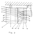
- the rollers 7, 8 have a rubber or other elastic covering, so that they are in the Do not damage the system on the pressure plate.
- the Execution can also be changed so that only one, possibly wider, on a piston rod 11, 23 Role is arranged. In the limit, only one can only first role are used, which is about half of the printing plate is sufficient, while a single one second roll in the area of the other half of the printing plate is employable.
- the rollers 7 and 8 together with the working cylinders 12 and 24 and the traverse 13 are in one Dirt protection 16 housed the latter is box-shaped trained and points to the forme cylinder 3 a pivotable opening flap 17.
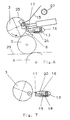
- a working cylinder 18 is attached, the piston rod 19 articulated via a coupling 20 with the opening flap 17 is connected to their actuation (Fig. 7).
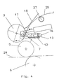
- roller guard 15 prevents the trailing End of the pressure plate 25 hooked.
- the opened opening flap 17 serves as an inlet protection for the inlet gap 28 between forme cylinder 3 and roller 7.
- the transfer cylinder is located 5 in the print position, so that at a plate change, i.e. both when plate mounting, as with the plate disassembly described below the web 29 to be printed later does not need to be capped.
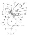
- FIG. 6 is the disassembly of the pressure plate 25 shown.
- the opening flap 17 of the dirt protection 16 is located by controlling the Working cylinder 18 already in the open position.
- Piston rods 23 By reversing the working cylinder 24 Piston rods 23 from the position shown in Fig. 2 brought into the position shown in Fig. 6, d. H. extended.
- the rollers 8 on the forme cylinder 3 approached and deliver the Roll contact when unwinding the pressure plate 25. Es So only these rolls 8 come with the colored, to be dismantled pressure plate 25 in contact and are soiled with paint. For mounting one new, clean pressure plate 25 are then again the clean rolls 7 available.
- Another rolling element with first and second Rollers 7, 8 is on the forme cylinder 4 of the lower one Printing unit 2 arranged.
- the attachment of the rollers 7, 8 takes place on the roller guard 30 at the pivot point 31 is mounted in the side walls 14. So they are first and second rollers 7, 8 together with the roller guard 30 around the pivot point 31 from the forme cylinder 4 can be swung away (dash-dotted lines Location in Fig. 1).
- the working cylinders 12, 18 and 24 are advantageous operated with compressed air.
- the compressed air for the working cylinder 18 in terms of their pressure limits that the actuated opening flap 17 at Open or close an operator's hands not injured.
Description
Eine Vorrichtung gem dem Oberbegriff vom Anspruch 1 zeigt die EP-B-214549.
- Fig. 1
- ein Doppeldruckwerk im Schnitt,
- Fig. 2
- die Ansicht Z nach Fig. 1,
- Fig. 3
- den Schnitt III-III nach Fig. 2,
- Fig. 4
- den Schnitt III-III nach Fig. 2 beim Klemmen der vorlaufenden Kante der Druckplatte,
- Fig. 5
- den Schnitt III-III nach Fig. 2 beim Aufziehen der Druckplatte,
- Fig. 6
- den Schnitt VI-VI nach Fig. 2 bei der Demontage der Druckplatte,
- Fig. 7
- den Schnitt VII-VII nach Fig. 2
Claims (7)
- Wälzelement zum Andrücken einer flexiblen Druckplatte an den Formzylinder eines Druckwerkes einer Rotationsdruckmaschine beim Plattenwechsel, wobei das Wälzelement aus mehreren längs des Mantels des Formzylinders angeordneten, einzeln an diesen anstellbaren Rollen besteht, wobei eine oder mehrere erste Rollen (7) lediglich bei der Montage der Druckplatte (25) und eine oder mehrere zweite Rollen (8) lediglich bei der Demontage der Druckplatte (25) im Bereich der Druckplatte (25) an den Formzylinder (3, 4) anstellbar sind, dadurch gekennzeichnet , daß das Wälzelement (7, 8) in einem Schmutzschutz (16) angeordnet ist, der Kastenforming ausgebildet ist und einem Formzylinder (3) um eine schwenkbar Offnungsklappe (17) aufweist, die aus einem zwischen dem Wälzelement (7, 8) und dem Formzylinder (3, 4) befindlichen Verstellbereich des Wälzelements (7, 8) wegschwenkbar ist.
- Wälzelement nach Anspruch 1, dadurch gekennzeichnet, daß erste und zweite Rollen (7, 8) jeweils im Wechsel nebeneinander am Formzylinder (3, 4) angeordnet sind.
- Wälzelement nach Anspruch 1 oder 2, dadurch gekennzeichnet, daß jeweils eine oder zwei erste Rollen (7) mittels eines Arbeitszylinders (12) an den Formzylinder (3) anstellbar sind, wobei die Rollen (7) auf einer Achse (10) drehbar gelagert sind, die an der Kolbenstange (11) des Arbeitszylinders (12) befestigt ist.
- Wälzelement nach Anspruch 1 oder 2, dadurch gekennzeichnet, daß jeweils eine oder zwei zweite Rollen (8) mittels eines Arbeitszylinders (24) an den Formzylinder (3) anstellbar sind, wobei die Rollen (8) auf einer Achse (22) drehbar gelagert sind, die an der Kolbenstange (23) des Arbeitszylinders (24) befestigt ist.
- Wälzelement nach Anspruch 3 oder 4, dadurch gekennzeichnet, daß die Arbeitszylinder (12, 24) an einer Traverse (13) angeordnet sind, die an einem schwenkbar in den Seitenwänden (14) des Druckwerks (1, 2) gelagerten Walzenschutz (15, 30) befestigt ist.
- Wälzelement nach Anspruch 1, dadurch gekennzeichnet, daß an dem Schmutzschutz (16) ein Arbeitszylinder (18) befestigt ist, dessen Kolbenstange (19) über eine Koppel (20) gelenkig mit der Öffnungsklappe (17) zu deren Betätigung verbunden ist.
- Wälzelement nach Anspruch 1, dadurch gekennzeichnet, daß die Öffnungsklappe (17) im geöffneten Zustand als Schutz für den Einlaufspalt zwischen der Rolle (7) und dem Formzylinder (3) dient.
Applications Claiming Priority (2)
| Application Number | Priority Date | Filing Date | Title |
|---|---|---|---|
| DE4440239 | 1994-11-10 | ||
| DE4440239A DE4440239C5 (de) | 1994-11-10 | 1994-11-10 | Wälzelement zum Andrücken einer flexiblen Druckplatte an den Formzylinder |
Publications (4)
| Publication Number | Publication Date |
|---|---|
| EP0712725A2 EP0712725A2 (de) | 1996-05-22 |
| EP0712725A3 EP0712725A3 (de) | 1996-06-05 |
| EP0712725B1 EP0712725B1 (de) | 1999-05-12 |
| EP0712725B2 true EP0712725B2 (de) | 2004-09-01 |
Family
ID=6533014
Family Applications (1)
| Application Number | Title | Priority Date | Filing Date |
|---|---|---|---|
| EP95117485A Expired - Lifetime EP0712725B2 (de) | 1994-11-10 | 1995-11-07 | Wälzelement zum Andrücken einer flexiblen Druckplatte an den Formzylinder |
Country Status (4)
| Country | Link |
|---|---|
| US (1) | US5617792A (de) |
| EP (1) | EP0712725B2 (de) |
| JP (1) | JP2922141B2 (de) |
| DE (2) | DE4440239C5 (de) |
Cited By (3)
| Publication number | Priority date | Publication date | Assignee | Title |
|---|---|---|---|---|
| DE102005017182A1 (de) * | 2005-04-13 | 2006-10-19 | Man Roland Druckmaschinen Ag | Vorrichtung und Verfahren zum Andrücken einer Bespannung an einen Druckwerkzylinder einer Rotationsdruckmaschine |
| EP2110246A2 (de) | 2008-04-18 | 2009-10-21 | manroland AG | Druckplattenwechselvorrichtung |
| EP2110247A2 (de) | 2008-04-18 | 2009-10-21 | Manroland AG | Verfahren zum Positionieren einer Druckplatte auf einem Formzylinder |
Families Citing this family (32)
| Publication number | Priority date | Publication date | Assignee | Title |
|---|---|---|---|---|
| DE10238177B3 (de) | 2002-08-21 | 2004-02-05 | Koenig & Bauer Ag | Vorrichtung zum Andrücken eines Aufzugs an einen Zylinder einer Druckmaschine mit Hilfe von in Umfangsrichtung des Zylinders voneinander beabstandeten ersten und zweiten Wälzelementen |
| EP0739728B1 (de) * | 1995-04-26 | 1999-02-10 | Heidelberger Druckmaschinen Aktiengesellschaft | Verfahren und Vorrichtung zum Aufspannen einer Druckplatte auf einen Zylinder |
| US6113346A (en) | 1996-07-31 | 2000-09-05 | Agfa Corporation | Method for loading and unloading a supply of plates in an automated plate handler |
| JP3059112B2 (ja) * | 1997-01-13 | 2000-07-04 | リョービ株式会社 | 印刷機における刷版の端部挿入装置 |
| JPH11170485A (ja) * | 1997-12-16 | 1999-06-29 | Komori Corp | 版交換装置 |
| DE19934271A1 (de) | 1998-11-13 | 2000-05-25 | Heidelberger Druckmasch Ag | Verschwenkbare Druckformwechseleinrichtung |
| DE10120952A1 (de) | 2000-05-17 | 2001-11-22 | Heidelberger Druckmasch Ag | An- und abstellbare Leitelemente für das Auswechseln eines Druckträgers |
| US6792860B2 (en) | 2000-05-17 | 2004-09-21 | Koenig & Bauer Aktiengesellschaft | Method and device for pressing a packing against a cylinder |
| DE10024329A1 (de) * | 2000-05-17 | 2001-11-22 | Koenig & Bauer Ag | Verfahren und Vorrichtungen zum Andrücken eines Aufzuges auf einen Zylinder |
| EP1282519B1 (de) * | 2000-05-17 | 2008-03-26 | Koenig & Bauer Aktiengesellschaft | Zylinder mit einer vorrichtung zum andrücken eines aufzuges auf diesen zylinder |
| ATE429333T1 (de) | 2001-10-05 | 2009-05-15 | Koenig & Bauer Ag | Rollenrotationsdruckmaschine |
| DE10306492B4 (de) * | 2002-03-21 | 2006-10-19 | Heidelberger Druckmaschinen Ag | Andrückvorrichtung einer Druck- oder Lackiermaschine |
| DE10238179B3 (de) | 2002-08-21 | 2004-01-08 | Koenig & Bauer Ag | Vorrichtung zum Führen eines Aufzugs an einen Zylinder einer Druckmaschine |
| DE10247587A1 (de) * | 2002-10-11 | 2004-04-22 | Man Roland Druckmaschinen Ag | Verfahren zur Montage und Demontage flexibler Druckplatten |
| DE20316404U1 (de) * | 2003-10-24 | 2003-12-24 | Man Roland Druckmaschinen Ag | Andrückelement in einer Druckmaschine |
| JP2005297440A (ja) * | 2004-04-14 | 2005-10-27 | Dainippon Screen Mfg Co Ltd | 印刷装置 |
| JP4904018B2 (ja) * | 2004-05-04 | 2012-03-28 | ハイデルベルガー ドルツクマシーネン アクチエンゲゼルシヤフト | 刷版搬送のための方法及び装置 |
| DE102005005570B4 (de) | 2004-05-04 | 2022-06-02 | Heidelberger Druckmaschinen Ag | Verfahren und Vorrichtung zum Druckplattentransport |
| DE102004022083B3 (de) * | 2004-05-05 | 2005-10-20 | Roland Man Druckmasch | Vorrichtung zur Durchführung eines Druckplattenwechsels an einem Formzylinder einer Druckmaschine |
| JP4751655B2 (ja) * | 2005-06-30 | 2011-08-17 | 株式会社小森コーポレーション | 版挿入装置 |
| DE102005031163A1 (de) * | 2005-07-04 | 2007-01-18 | Koenig & Bauer Ag | Verfahren und Vorrichtung zum Zu- und/oder Abführen einer Druckplatte auf eine bzw. von einer Auflagefläche eines Druckformzylinders |
| DE102005044223A1 (de) * | 2005-09-16 | 2007-03-29 | Man Roland Druckmaschinen Ag | Druckwerk einer Rollenrotationsdruckmaschine |
| DE202006020547U1 (de) | 2006-04-25 | 2008-11-27 | Manroland Ag | Druckwerk einer Rollenrotationsdruckmaschine |
| EP2049334A4 (de) * | 2006-08-08 | 2010-09-22 | Goss Int Americas Inc | Verfahren und vorrichtung zur verhinderung von plattenzylinderverunreinigung während eines plattenwechselvorgangs |
| JP2008096923A (ja) * | 2006-10-16 | 2008-04-24 | Fuji Xerox Co Ltd | 画像形成装置及びプロセスカートリッジ |
| DE102006050568B3 (de) * | 2006-10-26 | 2008-01-10 | Koenig & Bauer Aktiengesellschaft | Vorrichtung zum Andrücken eines Aufzugs an einen Zylinder |
| DE102006059772A1 (de) | 2006-12-15 | 2008-06-19 | Man Roland Druckmaschinen Ag | Vorrichtung zur Durchführung eines Druckplattenwechsels an einem Formzylinder einer Druckmaschine |
| DE102007049453A1 (de) * | 2007-10-16 | 2009-04-30 | Manroland Ag | Verfahren und Vorrichtung zum Druckplattenwechsel an einer Verarbeitungsmaschine |
| DE102010038348B3 (de) * | 2010-07-23 | 2011-12-29 | Koenig & Bauer Aktiengesellschaft | Rollenleiste |
| DE102010038999B4 (de) | 2010-08-06 | 2014-06-05 | Koenig & Bauer Aktiengesellschaft | Zuführeinrichtung zum Zuführen einer Druckform zu einem Formzylinder einer Druckeinheit |
| DE102010038997A1 (de) | 2010-08-06 | 2012-02-09 | Koenig & Bauer Aktiengesellschaft | Zuführeinrichtung zum Zuführen einer zumindest an ihrem in Produktionsrichtung vorlaufenden Ende einen abgekanteten Einhängeschenkel aufweisenden Druckform zu einem Formzylinder einer Druckeinheit |
| DE102010038998A1 (de) | 2010-08-06 | 2012-02-09 | Koenig & Bauer Aktiengesellschaft | Vorrichtung zum Abführen einer Druckform von einem in einem Gestell einer Druckeinheit angeordneten Formzylinder |
Citations (2)
| Publication number | Priority date | Publication date | Assignee | Title |
|---|---|---|---|---|
| JPH01176558A (ja) † | 1988-01-06 | 1989-07-12 | Mitsubishi Heavy Ind Ltd | 刷版の版胴への着脱ロボット用ハンド |
| EP0214549B1 (de) † | 1985-09-13 | 1991-10-09 | Toray Industries, Inc. | Druckmaschine und Verfahren zum Zuführen einer Druckplatte |
Family Cites Families (11)
| Publication number | Priority date | Publication date | Assignee | Title |
|---|---|---|---|---|
| US4727807A (en) * | 1985-09-30 | 1988-03-01 | Tokyo Kikai Seisakusho | Apparatus for automatically mounting and removing printing plates in rotary printing press |
| DE69018036T3 (de) * | 1989-12-06 | 2001-02-15 | Komori Printing Mach | Apparat zum Wechseln von Druckplatten für Druckpresse. |
| DE3940795A1 (de) * | 1989-12-09 | 1991-06-13 | Koenig & Bauer Ag | Verfahren und einrichtung zum automatischen zufuehren bzw. abfuehren einer druckplatte |
| DE3940796A1 (de) * | 1989-12-09 | 1991-06-13 | Koenig & Bauer Ag | Verfahren und einrichtung zum automatischen wechseln einer druckplatte |
| DE4218602C2 (de) * | 1991-08-28 | 1993-11-11 | Heidelberger Druckmasch Ag | Vorrichtung zum Einführen der Druckplattenhinterkante an einem Plattenzylinder |
| DE4130359C2 (de) * | 1991-09-12 | 1997-04-17 | Heidelberger Druckmasch Ag | Vorrichtung zum Ab- und/oder Zuführen von Druckplatten einer Druckmaschine |
| DE59304916D1 (de) * | 1992-09-18 | 1997-02-06 | Koenig & Bauer Albert Ag | Verfahren zum zuführen von druckplatten |
| DE4231906C2 (de) * | 1992-09-18 | 1995-10-12 | Koenig & Bauer Ag | Einrichtung zum Zuführen und Abführen von Druckplatten zu und von einem Plattenzylinder |
| FR2718674B1 (fr) * | 1994-04-18 | 1996-07-12 | Heidelberg Harris Sa | Dispositif d'échange de clichés de machines rotatives à imprimer. |
| DE4414443C1 (de) * | 1994-04-26 | 1995-11-30 | Heidelberger Druckmasch Ag | Vorrichtung zum Führen eines Druckträgers |
| US5558111A (en) * | 1995-02-02 | 1996-09-24 | International Business Machines Corporation | Apparatus and method for carrier backing film reconditioning |
-
1994
- 1994-11-10 DE DE4440239A patent/DE4440239C5/de not_active Expired - Fee Related
-
1995
- 1995-11-01 JP JP7285356A patent/JP2922141B2/ja not_active Expired - Fee Related
- 1995-11-07 DE DE59505896T patent/DE59505896D1/de not_active Expired - Lifetime
- 1995-11-07 EP EP95117485A patent/EP0712725B2/de not_active Expired - Lifetime
- 1995-11-13 US US08/555,915 patent/US5617792A/en not_active Expired - Lifetime
Patent Citations (2)
| Publication number | Priority date | Publication date | Assignee | Title |
|---|---|---|---|---|
| EP0214549B1 (de) † | 1985-09-13 | 1991-10-09 | Toray Industries, Inc. | Druckmaschine und Verfahren zum Zuführen einer Druckplatte |
| JPH01176558A (ja) † | 1988-01-06 | 1989-07-12 | Mitsubishi Heavy Ind Ltd | 刷版の版胴への着脱ロボット用ハンド |
Cited By (5)
| Publication number | Priority date | Publication date | Assignee | Title |
|---|---|---|---|---|
| DE102005017182A1 (de) * | 2005-04-13 | 2006-10-19 | Man Roland Druckmaschinen Ag | Vorrichtung und Verfahren zum Andrücken einer Bespannung an einen Druckwerkzylinder einer Rotationsdruckmaschine |
| EP2110246A2 (de) | 2008-04-18 | 2009-10-21 | manroland AG | Druckplattenwechselvorrichtung |
| EP2110247A2 (de) | 2008-04-18 | 2009-10-21 | Manroland AG | Verfahren zum Positionieren einer Druckplatte auf einem Formzylinder |
| DE102009004980A1 (de) | 2008-04-18 | 2009-10-22 | Manroland Ag | Verfahren zum Positionieren einer Druckplatte auf einem Formzylinder |
| DE102008019515A1 (de) | 2008-04-18 | 2009-10-22 | Manroland Ag | Druckplattenwechselvorrichtung |
Also Published As
| Publication number | Publication date |
|---|---|
| EP0712725A3 (de) | 1996-06-05 |
| EP0712725B1 (de) | 1999-05-12 |
| DE59505896D1 (de) | 1999-06-17 |
| JP2922141B2 (ja) | 1999-07-19 |
| DE4440239A1 (de) | 1996-05-15 |
| DE4440239C2 (de) | 1999-09-30 |
| US5617792A (en) | 1997-04-08 |
| DE4440239C5 (de) | 2007-11-22 |
| JPH08207249A (ja) | 1996-08-13 |
| EP0712725A2 (de) | 1996-05-22 |
Similar Documents
| Publication | Publication Date | Title |
|---|---|---|
| EP0712725B2 (de) | Wälzelement zum Andrücken einer flexiblen Druckplatte an den Formzylinder | |
| DE2815388C3 (de) | Vorrichtung zum Waschen von Zylindern an Druckmaschinen, insbesondere Offsetdruckmaschinen | |
| EP0432660B1 (de) | Einrichtung zum Wechseln einer Druckplatte | |
| DE3529865A1 (de) | Vorrichtung zur reinigung eines zylinders einer druckmaschine | |
| EP0243712A2 (de) | Waschvorrichtung für Druckzylinder von Druckmaschinen | |
| DE4209642A1 (de) | Vorrichtung zur wahlweisen Reinigung mehrerer Zylinder | |
| DE3735302C2 (de) | ||
| DE4215355A1 (de) | Waschvorrichtung für Zylinder in Druckmaschinen, insbesondere Bogenoffsetdruckmaschinen | |
| DE3806609C2 (de) | Waschvorrichtung zum Waschen der Mantelfläche eines Gummituchzylinders einer Offset-Druckmaschine | |
| EP0673765B1 (de) | Aufhängung für eine als Schutz vor den Druckwerkszylindern einer Druckmaschine dienenden Einrichtung | |
| DE4343692C2 (de) | Reinigungseinrichtung für einen Gummituch- oder Druckzylinder von Druckmaschinen, vorzugsweise Offsetdruckmaschinen | |
| EP0606581B1 (de) | Vorrichtung zum automatischen Reinigen von Gummituchzylindern in einer Offsetdruckmaschine | |
| DE1808909B2 (de) | Verfahren zum Reinigen des Plattenzylinders einer Offsetrotations-Druckmaschine und diesbezügliche Vorrichtung | |
| DE2646071C2 (de) | Farbwerk eines Druckwerkes für eine Fertigungsstraße der papierverarbeitenden Industrie | |
| DE4326833B4 (de) | Druckmaschinenzylinder-Waschvorrichtung | |
| DE10011429B4 (de) | Druckmaschine mit einer Reinigungseinrichtung zur Reinigung zweier Druckmaschinenzylinder | |
| DD274003A1 (de) | Rakeleinrichtung fuer offsetdruckmaschinen | |
| DE102007006063B4 (de) | Druckwerk einer Rotationsdruckmaschine | |
| EP1591250B1 (de) | Verfahren und Vorrichtungen zum Abstreifen eines Fluids von einer Walze | |
| DE19818666B4 (de) | Andrückvorrichtung in Druckwerken von Rotationsdruckmaschinen | |
| EP1215046A1 (de) | Druckmaschine mit Vorrichtung zur Klischeereinigung | |
| EP1720706B1 (de) | Fingerschutz an einem druckwerk mit einem presseur | |
| DE19909686A1 (de) | Einrichtung zur Steuerung der Greifer eines Druckzylinders einer Rotationsdruckmaschine | |
| DE4420971C1 (de) | Verfahren und Vorrichtung zum Aufziehen flexibler Druckformen | |
| DE2238039A1 (de) | Vorrichtung zum entfernen von fremdpartikeln von einer lithographischen druckpresse |
Legal Events
| Date | Code | Title | Description |
|---|---|---|---|
| PUAI | Public reference made under article 153(3) epc to a published international application that has entered the european phase |
Free format text: ORIGINAL CODE: 0009012 |
|
| PUAL | Search report despatched |
Free format text: ORIGINAL CODE: 0009013 |
|
| AK | Designated contracting states |
Kind code of ref document: A2 Designated state(s): CH DE FR GB IT LI SE |
|
| AK | Designated contracting states |
Kind code of ref document: A3 Designated state(s): CH DE FR GB IT LI SE |
|
| 17P | Request for examination filed |
Effective date: 19961113 |
|
| GRAG | Despatch of communication of intention to grant |
Free format text: ORIGINAL CODE: EPIDOS AGRA |
|
| 17Q | First examination report despatched |
Effective date: 19980706 |
|
| GRAG | Despatch of communication of intention to grant |
Free format text: ORIGINAL CODE: EPIDOS AGRA |
|
| GRAH | Despatch of communication of intention to grant a patent |
Free format text: ORIGINAL CODE: EPIDOS IGRA |
|
| GRAH | Despatch of communication of intention to grant a patent |
Free format text: ORIGINAL CODE: EPIDOS IGRA |
|
| GRAA | (expected) grant |
Free format text: ORIGINAL CODE: 0009210 |
|
| ITF | It: translation for a ep patent filed |
Owner name: BARZANO' E ZANARDO ROMA S.P.A. |
|
| AK | Designated contracting states |
Kind code of ref document: B1 Designated state(s): CH DE FR GB IT LI SE |
|
| REG | Reference to a national code |
Ref country code: CH Ref legal event code: NV Representative=s name: E. BLUM & CO. PATENTANWAELTE Ref country code: CH Ref legal event code: EP |
|
| REF | Corresponds to: |
Ref document number: 59505896 Country of ref document: DE Date of ref document: 19990617 |
|
| ET | Fr: translation filed | ||
| GBT | Gb: translation of ep patent filed (gb section 77(6)(a)/1977) |
Effective date: 19990812 |
|
| PLBI | Opposition filed |
Free format text: ORIGINAL CODE: 0009260 |
|
| PLBF | Reply of patent proprietor to notice(s) of opposition |
Free format text: ORIGINAL CODE: EPIDOS OBSO |
|
| 26 | Opposition filed |
Opponent name: KOENIG & BAUER AKTIENGESELLSCHAFT Effective date: 20000210 Opponent name: HEIDELBERGER DRUCKMASCHINEN AG Effective date: 20000209 |
|
| PLBF | Reply of patent proprietor to notice(s) of opposition |
Free format text: ORIGINAL CODE: EPIDOS OBSO |
|
| PLBF | Reply of patent proprietor to notice(s) of opposition |
Free format text: ORIGINAL CODE: EPIDOS OBSO |
|
| REG | Reference to a national code |
Ref country code: GB Ref legal event code: IF02 |
|
| PGFP | Annual fee paid to national office [announced via postgrant information from national office to epo] |
Ref country code: CH Payment date: 20031030 Year of fee payment: 9 |
|
| PGFP | Annual fee paid to national office [announced via postgrant information from national office to epo] |
Ref country code: SE Payment date: 20031103 Year of fee payment: 9 |
|
| PUAH | Patent maintained in amended form |
Free format text: ORIGINAL CODE: 0009272 |
|
| STAA | Information on the status of an ep patent application or granted ep patent |
Free format text: STATUS: PATENT MAINTAINED AS AMENDED |
|
| 27A | Patent maintained in amended form |
Effective date: 20040901 |
|
| AK | Designated contracting states |
Kind code of ref document: B2 Designated state(s): CH DE FR GB IT LI SE |
|
| REG | Reference to a national code |
Ref country code: CH Ref legal event code: AEN Free format text: AUFRECHTERHALTUNG DES PATENTES IN GEAENDERTER FORM |
|
| PG25 | Lapsed in a contracting state [announced via postgrant information from national office to epo] |
Ref country code: SE Free format text: LAPSE BECAUSE OF NON-PAYMENT OF DUE FEES Effective date: 20041108 |
|
| PG25 | Lapsed in a contracting state [announced via postgrant information from national office to epo] |
Ref country code: LI Free format text: LAPSE BECAUSE OF NON-PAYMENT OF DUE FEES Effective date: 20041130 Ref country code: CH Free format text: LAPSE BECAUSE OF NON-PAYMENT OF DUE FEES Effective date: 20041130 |
|
| GBTA | Gb: translation of amended ep patent filed (gb section 77(6)(b)/1977) | ||
| EUG | Se: european patent has lapsed | ||
| ET3 | Fr: translation filed ** decision concerning opposition | ||
| REG | Reference to a national code |
Ref country code: CH Ref legal event code: PL |
|
| PGFP | Annual fee paid to national office [announced via postgrant information from national office to epo] |
Ref country code: IT Payment date: 20081125 Year of fee payment: 14 |
|
| REG | Reference to a national code |
Ref country code: FR Ref legal event code: CD |
|
| PGFP | Annual fee paid to national office [announced via postgrant information from national office to epo] |
Ref country code: GB Payment date: 20081117 Year of fee payment: 14 |
|
| GBPC | Gb: european patent ceased through non-payment of renewal fee |
Effective date: 20091107 |
|
| PG25 | Lapsed in a contracting state [announced via postgrant information from national office to epo] |
Ref country code: GB Free format text: LAPSE BECAUSE OF NON-PAYMENT OF DUE FEES Effective date: 20091107 |
|
| PG25 | Lapsed in a contracting state [announced via postgrant information from national office to epo] |
Ref country code: IT Free format text: LAPSE BECAUSE OF NON-PAYMENT OF DUE FEES Effective date: 20091107 |
|
| REG | Reference to a national code |
Ref country code: DE Ref legal event code: R081 Ref document number: 59505896 Country of ref document: DE Owner name: MANROLAND WEB SYSTEMS GMBH, DE Free format text: FORMER OWNER: MANROLAND AG, 63075 OFFENBACH, DE Effective date: 20120626 |
|
| PGFP | Annual fee paid to national office [announced via postgrant information from national office to epo] |
Ref country code: FR Payment date: 20121130 Year of fee payment: 18 Ref country code: DE Payment date: 20121121 Year of fee payment: 18 |
|
| REG | Reference to a national code |
Ref country code: FR Ref legal event code: ST Effective date: 20140731 |
|
| PG25 | Lapsed in a contracting state [announced via postgrant information from national office to epo] |
Ref country code: DE Free format text: LAPSE BECAUSE OF NON-PAYMENT OF DUE FEES Effective date: 20140603 |
|
| REG | Reference to a national code |
Ref country code: DE Ref legal event code: R119 Ref document number: 59505896 Country of ref document: DE Effective date: 20140603 |
|
| PG25 | Lapsed in a contracting state [announced via postgrant information from national office to epo] |
Ref country code: FR Free format text: LAPSE BECAUSE OF NON-PAYMENT OF DUE FEES Effective date: 20131202 |