EP0714687A2 - Process and apparatus for dewater of sludge and like substances - Google Patents
Process and apparatus for dewater of sludge and like substances Download PDFInfo
- Publication number
- EP0714687A2 EP0714687A2 EP95118363A EP95118363A EP0714687A2 EP 0714687 A2 EP0714687 A2 EP 0714687A2 EP 95118363 A EP95118363 A EP 95118363A EP 95118363 A EP95118363 A EP 95118363A EP 0714687 A2 EP0714687 A2 EP 0714687A2
- Authority
- EP
- European Patent Office
- Prior art keywords
- sludge
- chamber
- pressure
- filter
- sludge chamber
- Prior art date
- Legal status (The legal status is an assumption and is not a legal conclusion. Google has not performed a legal analysis and makes no representation as to the accuracy of the status listed.)
- Granted
Links
Images


Classifications
-
- B—PERFORMING OPERATIONS; TRANSPORTING
- B01—PHYSICAL OR CHEMICAL PROCESSES OR APPARATUS IN GENERAL
- B01D—SEPARATION
- B01D25/00—Filters formed by clamping together several filtering elements or parts of such elements
- B01D25/12—Filter presses, i.e. of the plate or plate and frame type
- B01D25/127—Filter presses, i.e. of the plate or plate and frame type with one or more movable filter bands arranged to be clamped between the press plates or between a plate and a frame during filtration, e.g. zigzag endless filter bands
- B01D25/1275—Filter presses, i.e. of the plate or plate and frame type with one or more movable filter bands arranged to be clamped between the press plates or between a plate and a frame during filtration, e.g. zigzag endless filter bands the plates or the frames being placed in a non-vertical position
-
- B—PERFORMING OPERATIONS; TRANSPORTING
- B01—PHYSICAL OR CHEMICAL PROCESSES OR APPARATUS IN GENERAL
- B01D—SEPARATION
- B01D25/00—Filters formed by clamping together several filtering elements or parts of such elements
- B01D25/12—Filter presses, i.e. of the plate or plate and frame type
- B01D25/172—Plate spreading means
-
- B—PERFORMING OPERATIONS; TRANSPORTING
- B01—PHYSICAL OR CHEMICAL PROCESSES OR APPARATUS IN GENERAL
- B01D—SEPARATION
- B01D25/00—Filters formed by clamping together several filtering elements or parts of such elements
- B01D25/28—Leaching or washing filter cakes in the filter handling the filter cake for purposes other than regenerating
- B01D25/282—Leaching or washing filter cakes in the filter handling the filter cake for purposes other than regenerating for drying
- B01D25/285—Leaching or washing filter cakes in the filter handling the filter cake for purposes other than regenerating for drying by compression using inflatable membranes
-
- B—PERFORMING OPERATIONS; TRANSPORTING
- B01—PHYSICAL OR CHEMICAL PROCESSES OR APPARATUS IN GENERAL
- B01D—SEPARATION
- B01D25/00—Filters formed by clamping together several filtering elements or parts of such elements
- B01D25/28—Leaching or washing filter cakes in the filter handling the filter cake for purposes other than regenerating
- B01D25/282—Leaching or washing filter cakes in the filter handling the filter cake for purposes other than regenerating for drying
- B01D25/287—Leaching or washing filter cakes in the filter handling the filter cake for purposes other than regenerating for drying by compression using pistons
-
- B—PERFORMING OPERATIONS; TRANSPORTING
- B01—PHYSICAL OR CHEMICAL PROCESSES OR APPARATUS IN GENERAL
- B01D—SEPARATION
- B01D25/00—Filters formed by clamping together several filtering elements or parts of such elements
- B01D25/30—Feeding devices ; Discharge devices
-
- B—PERFORMING OPERATIONS; TRANSPORTING
- B01—PHYSICAL OR CHEMICAL PROCESSES OR APPARATUS IN GENERAL
- B01D—SEPARATION
- B01D25/00—Filters formed by clamping together several filtering elements or parts of such elements
- B01D25/32—Removal of the filter cakes
-
- B—PERFORMING OPERATIONS; TRANSPORTING
- B01—PHYSICAL OR CHEMICAL PROCESSES OR APPARATUS IN GENERAL
- B01D—SEPARATION
- B01D2201/00—Details relating to filtering apparatus
- B01D2201/20—Pressure-related systems for filters
- B01D2201/202—Systems for applying pressure to filters
Definitions
- the invention relates to a method for dewatering sludge and similar substances, in which the sludge is fed under pressure into at least one filter sludge-containing closed sludge chamber and in the sludge chamber a dehydrating hydrostatic pressure is built up Sludge chamber opened and the filter surfaces with the filter cake are moved out of the sludge chamber.
- dewater sludges and similar substances for example the sludge obtained in sewage treatment plants, after adding organic or inorganic flocculants or filter aids in chamber filter presses.
- the sludge is fed into filter chambers which are closed on all sides and the medium to be dewatered is pumped in by means of pumps until the desired dry matter content is reached.
- the filtrate contained in the medium to be dewatered is discharged through the partition walls of the individual filter chambers made of filter material.
- the invention has for its object to provide a completely new dewatering method and a device suitable for performing this method, in which the flocculation of the sludge is not destroyed during the build-up of the hydrostatic pressure, and in which with little technical Effort a significantly improved efficiency and moreover a significantly improved throughput is guaranteed.
- this object is essentially achieved in that the sludge is introduced into at least one intermediate container connected to the sludge chamber, that the sludge supply to the intermediate container is then separated, and that the hydrostatic pressure is then replaced by positive displacement of the Volume of sludge is generated from the intermediate container in the sludge chamber.
- the hydrostatic dewatering pressure can be built up gently without the flocculated sludge being mechanically influenced in such a way that the flocculation could be destroyed.
- the intermediate container receives a quantity of sludge which corresponds approximately to twice the volume of the sludge chamber.
- the invention can be further developed in an advantageous manner in that, after the sludge chamber has been filled, the hydrostatic pressure is generated by positive displacement of the part of the second filling of the intermediate container which exceeds the volume of the sludge chamber.
- the sludge is supplied to the intermediate container via an expansion tank, which is continuously filled with sludge. This achieves the advantage of a quasi-continuous mode of operation in that at least the sludge can be fed continuously.
- a preliminary dewatering of the sludge is carried out in the expansion tank.
- This represents something completely new in the field of chamber filter presses and the associated procedure and offers the advantage that the dewatering performance is increased considerably by achieving the desired dry matter contents in shorter working cycles, since the sludge chamber already has a higher dry matter content containing sludge.
- the stages work parallel to one another, which on the one hand achieves a considerable reduction in the cycle time in the sludge chamber and on the other hand greatly increases the throughput.
- the sludge chamber is separated from the intermediate container and then the volume of the sludge chamber is reduced, a mechanical drainage pressure being generated which is greater than the hydrostatic pressure previously reached.
- the sludge is introduced into the sludge chamber at several points simultaneously from a number of intermediate containers corresponding to the number of these points.
- the desired hydrostatic pressure is reached comparatively quickly by avoiding the need to transmit the filtration pressure through the entire substance in the chamber.
- Another object of the invention is a device for performing the above-described method with at least one side closed sludge chamber, which has filter surfaces and a sludge inlet, which is connected to a device generating a hydrostatic Filtration pressure, the filter surfaces between Pressure plates movable relative to each other are arranged, and the filter surfaces for discharging the filter cake are designed to be displaceable with respect to the sludge chamber after opening of the pressure plates, the object on which the invention is based is essentially achieved in that the device for generating the hydrostatic filtration pressure as one or is formed several intermediate containers that the intermediate container is designed as a piston-cylinder unit with a cylinder housing and a piston displaceable therein and a drive for the piston, the piston-cylinder unit having a sludge inlet and a sludge outlet connected to the sludge chamber, and that at the sludge inlet and at the sludge outlet alternately actuated blocking and control valves are provided.
- a particularly preferred embodiment consists in the fact that the sludge chamber has several sludge inlets, that a corresponding number of intermediate containers is provided, in which each sludge inlet is connected to one of the sludge inlets of the sludge chamber by a separate connecting line.
- the blocking and control valves are designed as ball valves. This ensures that the flocculated sludge is conveyed on particularly gently, in that ball valves of this type form the full line cross section and therefore do not offer any kinks or disturbances for the flow at which the flakes can be destroyed.
- the filter surfaces are straight back and forth slide filter tapes formed.
- the process of laboriously removing the sludge cake in known chamber filter presses is avoided by the filter belts, after dewatering, can laterally move the press cake obtained out of the opened sludge chamber, after which the filter cloths can then be cleaned in the simplest way while they are returning while they are back in the sludge chamber can be retracted.
- the sludge chamber is formed by an upper and lower filter surface, between which a flexible seal surrounding the sludge chamber is arranged.
- the seal is preferably attached to an auxiliary frame, the auxiliary frame being movably suspended from the upper pressure plate in a particularly preferred embodiment.
- the sludge chamber has an oval outline, since this results in a particularly favorable distribution of the pressure with respect to the seal surrounding the sludge chamber.
- each filter surface is supported on a bearing plate which is provided with channels open to the filter surface.
- the channels are parallel to the main axis of the sludge chamber, so that the filtrate exits at the end of the sludge chamber against the discharge direction due to the gradient.
- the lower pressure plate is supported on high-pressure generators, by means of which the volume of the sludge chamber can be reduced after the hydrostatic dewatering pressure has been reached in order to generate an additional, mechanical dewatering pressure.
- the lower pressure plate is designed as a hydraulic bed in that a number of high-pressure generators are arranged next to one another over the length and / or width of the lower pressure plate.
- the high pressure generators can each be arranged laterally outside the area of the sludge chamber.
- Hydraulic single cylinders are advantageously used as high pressure generators.
- This embodiment offers the advantage that the enormous pressures can be achieved with comparatively inexpensive high pressure generators, and at the same time bending stresses are avoided, since the high pressure is generated where it is needed, namely in the area of the surface area of the sludge chamber itself.
- the closed position of the sludge chamber is mechanically locked, wherein a pawl arrangement acting on the upper pressure plate is advantageously provided for locking.
- a plurality of sludge chambers are arranged one above the other.
- an intermediate plate is provided between the upper and the lower pressure plate, which has a bearing plate and a filter belt on each of its upper and lower sides, an auxiliary frame with a seal also being suspended on the underside.
- a preliminary dewatering device is provided in front of the intermediate container or containers, the sludge outlet of which is connected to the sludge feed line of the pressure container.
- the pre-dewatering device is advantageously designed as a surge tank, the inlet of which is connected to a continuous sludge supply.
- the pre-dewatering device has one or more filter baskets immersed in the sludge of the expansion tank, which are provided with a filtrate outlet.
- the filter basket (7) is arranged in a fixed position and that one or more brushes (38 B) are provided which reach over the height of the filter basket (7) and which run around on the filtrate side of the filter basket (7).
- the slowly rotating brushes significantly improve the dewatering behavior of the sludge without destroying the flocculation, since the brushes are arranged on the filtrate side.
- the invention can be further developed by providing stops defining the height of the sludge chamber between the pressure plates and / or intermediate plates. This feature is particularly advantageous in connection with the mechanical locking of the closed position of the sludge chambers, since this clearly defines the closed position.
- the volume of the sludge chamber is additionally reduced mechanically after the hydrostatic dewatering pressure has been reached, it is advantageous to compress the stops in accordance with the reduction in volume of the sludge chamber or the associated reduction in the height of the sludge chamber or train resilient.
- the invention furthermore relates to a seal for laterally sealing a pressure chamber which can be reduced in volume in the vertical direction, as is characterized in detail in the claims relating to this seal.
- FIGS. 1 to 4 To explain the different variants of the method according to the invention, reference is first made to the schematic representations according to FIGS. 1 to 4, in which various embodiments of the device according to the invention are shown with regard to their basic components.
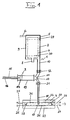
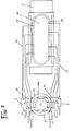
- FIG. 1 The basic principle of the method according to the invention is best seen in FIG. 1.
- the device shown there, generally designated 1, consists of three main components, namely a pre-dewatering stage 2, an intermediate container 3 and a filter press 4.
- the pre-dewatering stage 2 consists of an expansion tank 5 which is connected to a continuous sludge feed 6.
- a filter basket 7 is arranged, which has a filtrate outlet 8.
- the filter basket 7 is immersed in the sludge 9 fed into the expansion tank.
- the expansion tank 5 has at its lower end a sludge outlet line 10 which is connected to the sludge inlet 11 of the intermediate tank 3.
- a blocking or control valve 12 is provided in the sludge outlet line 10, through which the supply of sludge to the intermediate container 3 can be interrupted.
- the intermediate container 3 is designed in the manner of a large injection syringe as a piston-cylinder unit and consists of a cylinder housing 13 and a piston 14 which can be displaced therein and which is connected with its piston rod to a drive 15, which in the exemplary embodiment is formed by a hydraulic piston or pneumatic piston 16.
- the sludge outlet 17 of the intermediate container 3 is connected via a line 18 to the sludge inlet 19 of a sludge chamber 20 of the filter press 4, with a further blocking or control valve 21 being provided in the line 18.
- the sludge chamber 20 of the filter press 4 is arranged between an upper pressure plate 22 and a lower pressure plate 23, which individually or both can be designed to be movable in the vertical direction.
- the sludge chamber 20 is formed by an upper filter surface 24 and a lower filter surface 25, which consist of an upper filter belt 26 and a lower filter belt 27, which can be moved back and forth in a straight line in the horizontal direction.
- a seal 28 which surrounds the sludge chamber 20 and which, when the sludge chamber is closed, lies sealingly against the two filter belts 26 and 27.
- a respective bearing plate 31 is arranged between the pressure plates 22, 23 and the filter belts 26, 27, which has open channels or grooves on the side of the filter belts 26, 27 which are used to remove the serve through the filter tapes emerging. This is explained in more detail below with reference to the various embodiments of the device according to the invention.
- the sludge to be dewatered is continuously fed into the expansion tank 5 through the continuous sludge feed 6, an upper sludge level 29 or a lower sludge level 30 being able to be set depending on the operating state, which corresponds to the respective maximum conditions.
- the continuously supplied sludge is subjected to a continuous preliminary dewatering under the effect of gravity in the expansion tank 5, the resulting filtrate being discharged from the filtrate outlet 8 of the filter basket 7.
- the sludge 9 already has a dry substance content of about 20% at the sludge outlet line 10.
- a sludge supply is transferred in portions into the intermediate container 3 by opening the control valve 12, which is preferably designed as a ball valve, and moving the piston 14 backwards from its front position by the drive 15.
- This filling of the intermediate container 3 can be extremely gentle and slow, so that the flocculation of the sludge is retained.
- the intermediate container 3 receives a sludge supply which corresponds to approximately one and a half times the volume of the sludge chamber 20.
- the control valve 12 is closed and then the control valve 21 is opened. Thereafter, the sludge volume contained in the intermediate container 3 is positively displaced from the intermediate container, in which the piston 14 is moved into its forward position by the drive 15.
- a hydrostatic pressure is already built up in the sludge chamber 20, since the volume of the intermediate container 3 is greater than the volume of the sludge chamber 20.
- the control valve 21 is then closed again and the control valve 12 is opened and the piston 14 is again in its rear Position moved by the drive 15 so that the intermediate container 3 is filled again with mud.
- the control valve 12 is closed again and the control valve 21 is opened and the piston 14 is moved forward again, so that an increased hydrostatic pressure is built up in the sludge chamber 20 by this movement with positive displacement of the contained sludge volume, which pressure should preferably be up to about 5 bar.
- the control valve 21 After reaching the desired hydrostatic pressure in the sludge chamber 20, the control valve 21 is closed again and by opening the control valve 12, the intermediate container 3 is completely filled again and is ready for the next cycle. At the same time, the sludge chamber 20 is opened by appropriate movement of the pressure plates 22 and / or 23 and the sludge cake produced is discharged from the sludge chamber 20 by horizontal movement of the filter belts 26, 27.
- the filter belts 26 and 27 are cleaned by washing nozzles provided on both sides, while these are moved back to their starting position, after which the sludge chamber is closed again and the cycle described above can then be repeated.
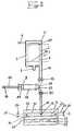
- the lower pressure plate 23 is mounted on a hydraulic bed 32, which consists of a plurality of high pressure generators 33 acting on the pressure plate 23.
- the volume of the sludge chamber 20 is increased by actuating the high pressure generator 33 reduced by pressing the lower pressure plate 23 upwards against the upper pressure plate 22.
- a mechanical drainage pressure is generated, which can be in the order of 30 bar, for example, and which is consequently greater than the hydrostatic pressure previously reached. This procedure enables a considerable, further increase in the dry matter content of the filter cake obtained.
- the high-pressure generator 33 is then relieved and the sludge chamber 20 is opened and the filter cake thus obtained is in turn discharged from the sludge chamber by horizontal movement of the filter belts 26 and 27.
- the sludge chamber is then closed again and the cycle described above can begin again.
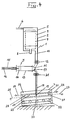
- the embodiment according to FIG. 3 essentially corresponds to the embodiment according to FIG. 2 with the difference that on the one hand dewatering is carried out simultaneously in a plurality of sludge chambers 20 arranged one above the other, and that the sludge is fed in simultaneously at several points in the sludge chamber 20 from a corresponding number of intermediate containers , and consequently the hydrostatic pressure is built up from several points in the individual sludge chambers 20.
- the structural details reference is made to the description below of the various embodiments of the device according to the invention.
- the intermediate container 3 supplying the upper sludge chamber 20 being illustrated in dashed lines.
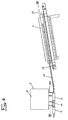
- FIG. 4 corresponds in essential details to the embodiment according to FIG. 2, see above that again the same reference numerals have been used for the same or equivalent parts.
- the sludge chamber 20 with the corresponding filter surfaces 25, 26 is arranged inclined to the horizontal, which serves to keep the filtrate emerging from the filter belts 26 and 27 above and below, which collects in the open channels of the bearing plates 31, constantly to be removed by gravity.
- FIGS. 5 to 13 For a description of a first practical embodiment of the device according to the invention, reference is made below to FIGS. 5 to 13, these figures dealing with technical details of the pre-dewatering stage 2, the intermediate container 3 and the associated filter press 4 connected to the intermediate container or containers 3.
- a filter basket 7 is provided in the expansion tank 5 of the pre-dewatering stage 2.
- a washing device 38 is provided, which consists of washing nozzles 38 A and at least one brush 38 B reaching over the height of the filter basket 7.
- a scraper 35 is provided on the inside of the filter basket 7, which can be moved up and down on a rod 35 A over the height of the filter basket 7.
- the unit consisting of the washing device 38 and the scraper 35 is driven in rotation via a drive 34, so that by rotating this unit and the upward and downward movement of the scraper 35, both the outside and the inside of the filter basket, which is cylindrical, are thoroughly cleaned can be.
- the scraper 35 mainly serves to periodically clean the bottom and the sludge outlets of the filter basket.
- the drive 34 is formed by an electric motor 35 and a spur gear 36.
- the brushes 35 b of which preferred three pieces are provided around the circumference of the filter basket, run slowly continuously around the filter basket, the bristles repeatedly entering the filter openings and activating the drainage.
- the filtrate flowing out of the filter basket 7 in accordance with the arrows 39 in FIGS. 5 and 8 is discharged to the outside through the filtrate outlet 8 provided in the bottom of the expansion tank 5.
- the partially dewatered sludge 9 inside the filter basket 7 can be withdrawn in portions into the corresponding number of intermediate containers 3 through a number of sludge outlet lines 10 under the control of a corresponding number of shut-off valves 12.
- the continuous sludge supply is formed by a mixer 40 which is fed by a continuously running pump and which is driven by a motor 41 and continuously feeds the sludge into the expansion tank 5.
- the mixer 40 is arranged upright and mixes the sludge with the flocculant, which is added by the metering device 40 B.
- the mixer 40 has a mixing and conveying screw 40 A, which is shown schematically in FIG. 5.
- a number of sludge outlets 10 A are provided in the bottom of the expansion tank 5 of the pre-dewatering stage 2, which are connected via the sludge outlet lines 10 to the sludge inlets 11 of the intermediate tank 3.
- the number of sludge outlets 10 A, the sludge outlet lines 10 and the intermediate container 3 corresponds to the number of sludge inlets 19 of the sludge chamber 20, as can best be seen from FIG.
- the sludge chamber 20 has a total of eight sludge inlets 19, which are each individually connected to eight intermediate containers 3 via eight lines 18.
- the eight intermediate containers 3 have a total volume which corresponds to one and a half times the volume of the sludge chamber 20.
- the intermediate container 3 is constructed from the basic principle like a large injection syringe, in which it is formed by a piston-cylinder unit 13, 14.
- the sludge inlet 11 connected to the sludge outlet line 10 is provided, in front of which the blocking and control valve 12 is arranged.
- the blocking and control valve 12 is designed as an electrically or hydraulically controlled ball valve in order to ensure that the flocculated sludge is conveyed as gently as possible, that is to say without cross-sectional changes or disturbances.
- the sludge outlet 17 of the intermediate container 3 is provided, which is connected to the line 18 and in front of which the second blocking and control valve 21 is arranged.
- the blocking and control valve 21 is also designed as an electrically or hydraulically controlled ball valve.
- the piston 14 is displaceably arranged back and forth, by means of which the positive displacement of the sludge volume in the intermediate container 3 takes place.
- the piston 14 has a drive 15 which is formed by a hydraulic or pneumatic piston 16 which is arranged displaceably in a cylinder 117 and is connected to the piston 14 via its piston rod 116.
- a lubricant container 103 is additionally provided in the embodiment according to FIG. 9, which is connected to an inlet 105 into the cylinder 13, which lies on the rear side of the piston 14.
- a valve 106 is additionally provided for maintenance work.
- the arrangement is such that when the piston 14 is moved forward by the drive 15 and displaces the sludge volume from the intermediate container, lubricant is simultaneously sucked in from the lubricant container 103 on the rear side of the piston, and thus the cylinder 13 is constantly lubricated becomes.
- the control valve 12 is opened and the control valve 21 is closed and the piston 14 is moved rearward and draws in a new volume of sludge from the expansion tank 5, the lubricant located behind the piston 14 in the cylinder 13 is displaced back into the lubricant tank 103.
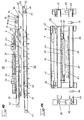
- FIGS. 5 to 8 The filter press 4 illustrated in FIGS. 5 to 8 is described in more detail below in connection with FIG. 5 with a special reference to FIGS. 16 and 17.
- FIGS. 10 to 15 show details of the filter press 4 associated with the preliminary dewatering stage 2 and the intermediate containers 3 according to FIGS. 5 to 9, the basic structure of which corresponds to the procedure according to FIG. 1, but the technical possibilities are shown in FIGS. 14 and 15 are to increase the number of sludge chambers 20.
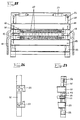
- FIGS. 10 to 13 show the filter press 4 in the two basic positions, namely once the open position according to FIGS. 10 and 11 for removing the filter cake and cleaning the filter surfaces and the closed position according to FIGS. 12 and 13, in which the sludge chamber is filled and drainage under hydrostatic Pressure is carried out according to the procedure shown in FIG. 1.
- the filter press shown in FIGS. 10 to 13 has the upper pressure plate 22 and the lower pressure plate 23, the upper pressure plate 22 being able to be raised and lowered relative to the lower pressure plate 23 by means of lifting cylinders 42 (FIG. 11).
- the bearing plate 31 Attached to the upper pressure plate 22 and the lower pressure plate 23 on the side facing the sludge chamber 20 is the bearing plate 31, which has channels 75 open in the direction of the sludge chamber 20 for discharging the filtrate.
- the bearing plates preferably consist of a low-friction plastic, since the filter belts 26 and 27 forming the upper and lower filter surfaces 24 and 25 slide on these bearing plates 31.
- the channels 75 of the bearing plates 31, which are illustrated only schematically in the figures of the drawings, are arranged such that they run in a straight line in the longitudinal direction of the sludge chambers 20 parallel to the main axis. Due to the gradient, this ensures that the filtrate collecting in the channels 75 is discharged against the discharge direction of the filter press on the front side of the bearing plates 31 under the action of gravity.
- the filter belts 26 and 27 are horizontally movable back and forth in the illustrated embodiment.
- the upper filter belt 26 is held at both ends by a reversible winding drive 44, so that the filter belt 26 is wound once onto the left winding drive 43, ie the filter surface 24 is moved into the sludge chamber 20, and in the opposite case the filter belt 26 is wound onto the right winding drive 44, ie the filter surface 24 is moved out of the sludge chamber 20.
- the filter belt 26 is still guided around a deflecting roller 46, to which a stripper 47 is assigned, which wipes off any residues of the filter cake adhering to the filter belt 26 during discharge.
- a swivel nozzle 49 which can be pivoted via a drive 48 and which, when the sludge chamber 20 is open and when the filter belts 26, 27 move back into the sludge chamber 20 after the filter cake has been dropped into the gap between the upper pressure plate 22 and the lower pressure plate 23 can be pivoted in order to wash both filter belts 26 and 27.
- the lower filter belt 27 is also received in accordance with the upper filter belt 26 by two winding drives 50 and 51, which are operated synchronously with the winding drives 43 and 44.
- the lower filter belt 27 is also guided around a deflection roller 52 with a scraper 53.
- the sludge inlets 19 into the sludge chamber 20, which are connected via a corresponding number of lines 18 to the likewise corresponding number of intermediate containers 3, are designed as horizontal, slit-like openings in the seal 28 surrounding the sludge chamber 20.
- a pawl device 54 is provided in the filter press 4 according to the invention, which consists of a number of pivotable pawls 55, which are mounted on a common axis 56 along both side edges of the filter press 4, each of the axes via pneumatic cylinders 57 and a lever drive 58 between the open position shown in FIGS. 10 and 11 and the locked position shown in FIGS. 12 and 13.
- effective stops 59 are provided between the upper pressure plate 22 and the lower pressure plate 23, by means of which the height of the closed sludge chamber 20 to be achieved when the upper pressure plate 22 is in a lowered position is determined.
- the filter press 4 is preferably set up in such a way that the sludge chamber 20 is inclined with respect to the horizontal, the inclination corresponding approximately to a gradient of the filter surfaces 24 and 25 of 5 °. This ensures that the filtrate entering the channels of the bearing plate 31 from the upper filter surface 24 is removed during the drainage due to the gradient.
- the sludge chamber is formed by the flexible seal 28 surrounding the sludge chamber 20 and the area of the filter belts 26 and 27 enclosed by it.
- the details of the seal 28 itself will be discussed in more detail below.
- the seal 28 is carried by an auxiliary frame 60 which is movably suspended up and down by means of push rods 61 on the upper pressure plate. This type of suspension is useful so that the sludge chamber 20 can be closed securely when the upper pressure plate 22 is lowered in the direction of the lower pressure plate 23 until the stops 59 are reached by relieving the lifting cylinders 42.
- the push rods 61 thus form drivers 62, which allow a limited relative movement between the upper pressure plate 22 and the seal 28.
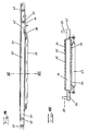
- FIGS. 14 and 15 show a modular component in the form of an intermediate plate 63, by means of which the number of sludge chambers 20 arranged one above the other in the filter press 4 according to FIGS. 10 to 13 and likewise can increase arbitrarily in the embodiments described below.
- an intermediate plate 63 according to FIGS. 14 and 15 between the upper pressure plate 22 and the lower pressure plate 23, a further sludge chamber 20 is formed in each case.
- such an intermediate plate is loaded on both sides with the same pressure, since in the sludge chambers 20 lying one above the other the same drainage pressure is built up, its support plate 64 can consist, for example, of a light grating, since only a certain pressure resistance is important.
- each intermediate plate has on its upper and lower side one of the bearing plates 31 on which an upper filter belt 65 and a lower filter belt 66 slide.
- Corresponding winding drives 67, 68, 69 and 70 with the associated deflection rollers, wipers and a washing device are also provided on the intermediate plate 63 for the filter belts, which are identical to the details described above which are described with reference to the upper and lower pressure plates 22 and 23 have been described.
- the winding drives and the associated auxiliary devices for the two filter belts 65 and 66 are merely arranged in the intermediate plate 63.
- a seal 28 is also suspended with its subframe 60 in drivers 62.
- the stops 59 are also provided on the side edges of the intermediate plate 63.
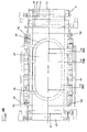
- FIGS. 16 to 27 illustrate a further practical embodiment of the device according to the invention, as is useful for carrying out the method according to FIGS. 2 to 4, in particular according to FIG. 3.
- FIG. 16 shows a side sectional view of the filter press 4, wherein the pre-dewatering device and the intermediate container 3 can be designed in accordance with FIGS. 5 to 9.
- the different operating states and the corresponding different positions of the individual components are also shown separated by the section lines XIX, XXII and XXV.
- the lower pressure plate 23 is also designed to be movable and serves to generate an additional mechanical drainage pressure by reducing the height of the sludge chambers 20 after the desired hydrostatic drainage pressure, which is set by the volume advance by means of the intermediate container 3, is achieved.
- the lower pressure plate 23 is mounted on a number of the high pressure generators 33 mentioned above, which, as in the exemplary embodiment according to FIGS. 16 to 27, can either be arranged in two rows along the longitudinal edges of the lower pressure plate 23, or which, as described above, can be designed as a hydraulic bed 32.
- each sludge chamber 20 is preferably oval in outline so that no corners and the like with corresponding pressure peaks arise.
- FIG. 17 shows in the upper half how the sludge inlets 19 are arranged and designed in the seal 28 and that each of the sludge inlets 19 is assigned its own connecting line 18, which is separated with a sludge outlet 17 of an intermediate container 3 is connected.
- the stops 59 are also adapted to the changed requirements of this embodiment, in that the stops 59 have an upper part 73, which can either be resiliently pressed into the stop 59 or forms part of a correspondingly lowerable hydraulic cylinder .
- FIGS. 19 to 22 show the opened state of the sludge chambers 20, the lifting cylinders 42 lifting the upper pressure plate 22 upwards.
- the pawls 55 are opened by being pivoted into the open position by the pneumatic cylinders 57.
- the seal 28 of the upper sludge chamber 20 was first lifted from the top of the intermediate plate 63 by the catches 62 and then the entire intermediate plate 63 was moved upwards by the catches 71 together with their associated seal 28 from the lower pressure plate 23 , wherein the associated seal 28 of the intermediate plate 63 was also carried by the driver 62 of the intermediate plate 63.
- the high pressure generator 33 was relieved at the same time, so that in the state shown in FIG. 19 the lower pressure plate 23 has also been lowered, which is supported by the fact that it absorbs the reaction forces of the lifting cylinders 42.
- the stops 59 are also relieved in this state and assume the position shown in FIG. 21, in which the upper parts 73 define the height of the closed sludge chambers.
- the filter press 43 is ready to discharge the filter cake 74 formed in a previous cycle from the sludge chambers 20.
- the winding drives 44, 51 and 65, 68 assigned to the discharge end 45 of the filter press 4 are now actuated, while the winding drives 43, 50 and 67, 69 assigned to the other end of the filter press are released.
- the filter belts 26, 27 and 65, 66 are moved out of the sludge chambers 20 synchronously and after the filter cake 74 has been ejected, the winding drives 44, 51 and 68, 70 are released and the winding drives 43, 50, 67 and 69 are actuated so that the filter belts 26, 27 and 65, 66 are in turn moved back synchronously into the sludge chambers 20. At the same time, the filter belts are cleaned by means of the washing nozzles 49. At the end of this process, the filter press 4 is again in the state according to FIG. 19, but no filter cake 74 is contained in the sludge chambers 20.
- the filter press 4 is then transferred to the state according to FIGS. 22 to 24, the sludge chambers 20 being closed.
- the lifting cylinders 42 are relieved and, taking the seals 28 and the intermediate plate 63 with them, lower the upper pressure plate 22 onto the lower pressure plate 23.
- the high pressure generator 33 remain in the unloaded state.
- the upper pressure plate 22 and the intermediate plate 63 are lowered until they come into engagement with the upper parts 73 of the stops 59.
- the pawls 55 are locked by actuating the pneumatic cylinders 57 and are pivoted into the position shown in FIG. 22, in which the distance between the upper pressure plate 22 and the lower pressure plate 23 is mechanically fixed and fixed by the stops 59.
- the filtrate contained in the sludge is pressed outwards through the filter belts 26, 27 and 65, 66 into the channels in the bearing plates 31 and is opposed due to the arrangement of the channels 75 parallel to the main axis of the sludge chamber 20 and due to the gradient the discharge direction at the end of the filter press 4.
- shut-off valves 21 After reaching the desired hydrostatic pressure in the sludge chambers, for example after reaching 5 bar, the shut-off valves 21 are closed again and then the shut-off valves 12 are opened, the pistons 14 being retracted and taking over a new sludge volume in the intermediate container 3.
- the high pressure generators 33 are then actuated in order to mechanically reduce the volume of the sludge chambers 20 in the vertical direction and thus to generate an additional mechanical dewatering pressure which is possibly considerably above the hydrostatic dewatering pressure.
- This process is illustrated in FIGS. 25 to 27, the high-pressure generator 33 being illustrated in its fully extended position, in which the highest dewatering pressure was reached.
- the pawls 55 are still closed and the lower pressure plate 23 has been moved upwards by the high pressure generator 33 against the upper pressure plate 22.
- the upper parts 73 of the stops 59 were pressed into the stops 59 in this process in order to enable the distance between the lower pressure plate 23 and the intermediate plate 63 and the intermediate plate 63 and the upper pressure plate 22 to be reduced.
- FIG. 25 shows how the catches 62 or 71 and 72 enable these relative movements.
- the filter press 4 is thus ready for the further beginning of a cycle which, as described above, begins with the extension and throwing out of the filter cake 74 produced.
- FIGS. 28 and 29 illustrate a further embodiment of the filter press 4 in a lateral schematic view or a sectional view along the line 29 XXIX of FIG. 28, as has already been shown in principle in FIGS. 5 to 7.
- the embodiment illustrated in FIGS. 28 and 29 is a particularly simple embodiment with only one sludge chamber 20.
- the sludge chamber 20 has only one filter surface 25, which is formed by the lower filter belt 27 on the bearing plate 31.
- the sludge chamber 20 is enclosed on the top by the seal 28 on the upper pressure plate 22 and the pressure plate 22 itself.
- the sludge chamber 20 is directly delimited on the upper side by the pressure plate 22, the sludge inlets 19 are provided directly in the upper pressure plate 22.
- the control valves 21 are also arranged in the upper pressure plate 22 in the lines 18, so that the sludge volume in the lines 18 which is acted upon by the mechanical drainage pressure is thereby reduced.
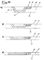
- FIGS. 30 and 31 particularly preferred embodiments of the seal 28 are shown in sectional views, which are generally suitable for the lateral sealing of pressure chambers that can be reduced in volume in the vertical direction.
- FIG. 30 shows the various operating states of the seal according to a to d, in which the position is illustrated in which the sludge chamber 20 is closed and the hydrostatic pressure is built up by means of the intermediate container 3.
- FIGS. 30 b to 30 d show the progressive deformation of the seal 28 during the generation of the mechanical drainage pressure in the filter press 4.
- the seal 28 is made in one piece, the circumference of the pressure chamber, i.e. in the embodiment of the sludge chamber 20 surrounding elastic body made of rubber or other suitable material.
- the body 80 has an approximately shell-like shape in cross section, which can be converted into a practically flat shape between the states a to d.
- the seal 28 is fastened to the upper pressure plate 22 by a frame 81 by means of bolts 82, the frame 81 simultaneously representing a stop for the maximum closing movement of the pressure chamber 20.
- the beveling of the profile of both the seal 28 and the frame 81 ensures that when the volume of the pressure chamber 20 is reduced, the sludge located near the seal 28 is displaced and moved towards the interior of the pressure chamber 20.
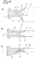
- FIG. 31 An embodiment of the seal 28 is illustrated in FIG. 31, as is useful in the case of filter surfaces located opposite one another in pressure chambers.
- FIG. 31 shows three different operating states of the seal 28, the mud inlet 19 leading through the seal 28 into the mud chamber 20 being shown simultaneously in the middle operating state b.
- the seal 28 consists of an integral elastic body made of rubber or another suitable material surrounding the circumference of the pressure chamber, in the embodiment of the mud chamber 20.
- the body 80 has the shape of a lying V in cross section, the tip of which is directed outward from the mud chamber 20.
- the free ends 88 and 89 of the V each form a sealing lip 83 and 84, which rests on the associated filter surface.
- a kink 85 and 86 is provided, at which the angle enclosed between the legs of the V increases.
- the angular increase at the kink 86 is a multiple of the angular increase at the kink 85, since when the mechanical drainage pressure in the sludge chamber 20 builds up, the lower filter surface is moved toward the upper filter surface.
- the symmetrical part of the V lies in a section 90 of the cross section of the seal 28, which is practically rectangular and forms an incision in this section 90, the lower leg of the symmetrical part of the V running parallel to the side edge of the rectangle.
- the rectangular section 90 is provided with a circumferential clamping or fastening projection 87 which is clamped in the auxiliary frame 60 in the exemplary embodiment of the device according to the present invention.
- the vertical distance between the sealing lips 83 and 84 in their relaxed state is approximately 80 mm.
- the distance between the sealing lips 83 and 84 is then about 60 mm. If, after reaching the hydrostatic dewatering pressure, the switch is made to the additional mechanical dewatering, the seal 28 can be compressed so far during this process that the distance between the sealing lips 83 and 84 is only about 30 to 35 mm, as shown in FIG. 3 c is.
Abstract
Description
Die Erfindung betrifft ein Verfahren zum Entwässern von Schlämmen und ähnlichen Substanzen, bei dem der Schlamm unter Druck in mindestens eine Filterflächen aufweisende geschlossene Schlammkammer eingespeist und in der Schlammkammer ein die Entwässerung herbeiführender hydrostatischer Druck aufgebaut wird, wobei nach erfolgter Entwässerung zum Abfördern des hergestellten Filterkuchens die Schlammkammer geöffnet und die Filterflächen mit dem Filterkuchen aus der Schlammkammer herausbewegt werden.The invention relates to a method for dewatering sludge and similar substances, in which the sludge is fed under pressure into at least one filter sludge-containing closed sludge chamber and in the sludge chamber a dehydrating hydrostatic pressure is built up Sludge chamber opened and the filter surfaces with the filter cake are moved out of the sludge chamber.
Es ist allgemein bekannt, Schlämme und ähnliche Substanzen, beispielsweise den in Abwasserkläranlagen anfallenden Schlamm, nach Zusatz organischer oder anorganischer Flokkungsmittel oder Filterhilfsmittel in Kammerfilterpressen zu entwässern. Bei Kammerfilterpressen der üblichen Bauart wird der Schlamm in allseitig geschlossene Filterkammern eingespeist und mittels Pumpen das zu entwässernde Medium mit hohem Druck so lange nachgepumpt, bis der gewünschte Gehalt an Trockensubstanz erreicht ist. Das in dem zu entwässernden Medium enthaltene Filtrat wird hierbei durch die aus Filtermaterial bestehenden Trennwandungen der einzelnen Filterkammern abgeführt. Nachteil bekannter Kammerfilterpressen dieser Bauart und der entsprechenden Verfahrensweise beim Entwässern ist es, daß bei sehr hohem technischen Aufwand der Wirkungsgrad, mit welchem der Druck auf die zu entwässernde Substanz übertragen wird, von Kammer zu Kammer in Förderrichtung abnimmt. Darüber hinaus wird der hydrostatische Entwässerungsdruck durch Pumpen aufgebaut, was den erheblichen Nachteil mit sich bringt, daß die durch die Flockungsmittel oder andere Filterhilfsmittel hergestellte Flockung des Schlamms beim Pumpen wieder zerstört wird. Ein weiterer Nachteil besteht in der deskontinuierlichen Arbeitsweise bekannter Kammerfilterpressen, da beim Öffnen der Schlammkammer die Schlammzufuhr unterbrochen werden muß. Darüberhinaus erfolgt die gesamte Entwässerung, einschließlich der Vorentwässerung bei niedrigem Druck, in der für hohe Drücke angelegten Kammer, so daß diese ausgesprochen unwirtschaftlich genutzt wird.It is generally known to dewater sludges and similar substances, for example the sludge obtained in sewage treatment plants, after adding organic or inorganic flocculants or filter aids in chamber filter presses. In chamber filter presses of the usual design, the sludge is fed into filter chambers which are closed on all sides and the medium to be dewatered is pumped in by means of pumps until the desired dry matter content is reached. The filtrate contained in the medium to be dewatered is discharged through the partition walls of the individual filter chambers made of filter material. Disadvantage of known chamber filter presses of this type and the corresponding procedure in the case of dewatering, the efficiency with which the pressure is transferred to the substance to be dewatered decreases from chamber to chamber in the conveying direction with very high technical outlay. In addition, the hydrostatic dewatering pressure is built up by pumps, which has the considerable disadvantage that the flocculation of the sludge produced by the flocculants or other filter aids is destroyed again during pumping. Another disadvantage is the continuous operation of known chamber filter presses, since the sludge feed must be interrupted when the sludge chamber is opened. In addition, the entire drainage, including the pre-drainage at low pressure, takes place in the chamber designed for high pressures, so that it is used extremely inefficiently.
Ausgehend von diesem Stand der Technik liegt der Erfindung die Aufgabe zugrunde, ein völlig neuartiges Entwässerungsverfahren und eine zur Durchführung dieses Verfahrens geeignete Vorrichtung zu schaffen, bei welchem während des Aufbaus des hydrostatischen Drucks die Flockung des Schlamms nicht zerstört wird, und bei welchem bei geringem technischem Aufwand ein erheblich verbesserter Wirkungsgrad und darüber hinaus ein wesentlich verbesserter Durchsatz gewährleistet ist.Based on this prior art, the invention has for its object to provide a completely new dewatering method and a device suitable for performing this method, in which the flocculation of the sludge is not destroyed during the build-up of the hydrostatic pressure, and in which with little technical Effort a significantly improved efficiency and moreover a significantly improved throughput is guaranteed.
Bei einem Verfahren der eingangs genannten Art wird diese Aufgabe im wesentlichen dadurch gelöst, daß der Schlamm in mindestens einen mit der Schlammkammer in Verbindung stehenden Zwischenbehälter eingebracht wird, daß danach die Schlammzufuhr zum Zwischenbehälter getrennt wird, und daß anschließnd der hydrostatische Druck durch positive Verdrängung des Schlammvolumens aus dem Zwischenbehälter in die Schlammkammer erzeugt wird. Es ist offensichtlich, daß hierbei mit einfachsten Mitteln, nämlich eines Zwischenbehälters, welcher eine positive Volumenverdrängung ermöglicht, indem beispielsweise der Zwischenbehälter als Kolbenzylindereinrichtung ausgebildet ist, auf ausgesprochen schonende Weise der hydrostatische Entwässerungsdruck aufgebaut werden kann, ohne daß der geflockte Schlamm mechanisch derart beeinflußt wird, daß die Flockung zerstört werden könnte.In a method of the type mentioned, this object is essentially achieved in that the sludge is introduced into at least one intermediate container connected to the sludge chamber, that the sludge supply to the intermediate container is then separated, and that the hydrostatic pressure is then replaced by positive displacement of the Volume of sludge is generated from the intermediate container in the sludge chamber. It is obvious that here with the simplest means, namely an intermediate container, which enables positive displacement, for example by the intermediate container being designed as a piston-cylinder device the hydrostatic dewatering pressure can be built up gently without the flocculated sludge being mechanically influenced in such a way that the flocculation could be destroyed.
Bevorzugt ist es hierbei, daß der Zwischenbehälter eine Schlammenge aufnimmt, die etwa dem Zweifachen des Volumens der Schlammkammer entspricht.It is preferred in this case that the intermediate container receives a quantity of sludge which corresponds approximately to twice the volume of the sludge chamber.
Im einzelnen kann die Erfindung in vorteilhafter Weise dadurch weitergebildet werden, daß nach dem Füllen der Schlammkammer der hydrostatische Druck durch positive Verdrängung des das Volumen der Schlammkammer übersteigenden Teils der zweiten Füllung des Zwischenbehälters erzeugt wird.In particular, the invention can be further developed in an advantageous manner in that, after the sludge chamber has been filled, the hydrostatic pressure is generated by positive displacement of the part of the second filling of the intermediate container which exceeds the volume of the sludge chamber.
Im einzelnen wird es bevorzugt, je nach spezifischem Entwässerungsverhalten des Schlamms,einen hydrostatischen Druck von etwa 5 bis 10 bar zu erzeugen, da dies mit einfachsten Mitteln und geringem konstruktiven Aufwand erfolgen kann.In particular, depending on the specific dewatering behavior of the sludge, it is preferred to generate a hydrostatic pressure of about 5 to 10 bar, since this can be done with the simplest means and with little design effort.
Bei einer besonders bevorzugten Ausführungsform nach der Erfindung erfolgt die Schlammzufuhr zu dem Zwischenbehälter über einen Ausgleichsbehälter, welcher kontinuierlich mit Schlamm befüllt wird. Hierdurch wird der Vorteil einer quasi kontinuierlichen Arbeitsweise erreicht, indem zumindest die Schlammzufuhr kontinuierlich erfolgen kann.In a particularly preferred embodiment according to the invention, the sludge is supplied to the intermediate container via an expansion tank, which is continuously filled with sludge. This achieves the advantage of a quasi-continuous mode of operation in that at least the sludge can be fed continuously.
Bei einer vorteilhaften Weiterbildung nach der Erfindung wird in dem Ausgleichsbehälter gleichzeitig eine Vorentwässerung des Schlamms duchgeführt. Dies stellt auf dem Gebiet der Kammerfilterpressen und der damit verbundenen Verfahrensweise etwas völlig Neuartiges dar und bietet den Vorteil, daß hierdurch die Entwässerungsleistung erheblich gesteigert wird, indem die angestrebten Trockensubstanzgehalte in kürzeren Arbeitszyklen erreichen werden, da die Schlammkammer mit bereits einen höheren Trockensubstanzgehalt aufweisendem Schlamm beschickt wird. Im Gegensatz zum Stand der Technik, bei welchem die verschiedenen Entwässerungsstufen nacheinander innerhalb der gleichen Kammer durchgeführt werden, arbeiten erfindungsgemäß die Stufen parallel zueinander, wodurch einerseits eine erhebliche Verkürzung der Zykluszeit in der Schlammkammer erreicht wird und andererseits die Durchsatzleistung stark vergrößert wird.In an advantageous development according to the invention, a preliminary dewatering of the sludge is carried out in the expansion tank. This represents something completely new in the field of chamber filter presses and the associated procedure and offers the advantage that the dewatering performance is increased considerably by achieving the desired dry matter contents in shorter working cycles, since the sludge chamber already has a higher dry matter content containing sludge. In contrast to the prior art, in which the different dewatering stages are carried out one after the other within the same chamber, according to the invention the stages work parallel to one another, which on the one hand achieves a considerable reduction in the cycle time in the sludge chamber and on the other hand greatly increases the throughput.
Bei einer besonders vorteilhaften Weiterbildung nach der Erfindung wird nach Erreichen eines festlegbaren hydrostatischen Druck in der Schlammkammer diese von dem Zwischenbehälter getrennt und anschließend das Volumen der Schlammkammer verkleinert, wobei ein mechanischer Entwässerungsdruck erzeugt wird, welcher größer ist als der zuvor erreichte hydrostatische Druck. Auf diese Weise wird erreicht, daß ab dem Druckniveau, ab welchem eine weitere Entwässerung durch den hydrostatischen Druck nur mit entsprechend hohen Energiekosten und entsprechend hohem Aufwand konstruktiver Art sowie größerem Zeitaufwand möglich wäre, die dann von dem Druckbehälter getrennte Schlammkammer mechanisch zusammengedrückt wird, so daß eine weitere Entwässerung durch den mechanisch erzeugten Druck erfolgt.In a particularly advantageous further development according to the invention, after a definable hydrostatic pressure in the sludge chamber is reached, the sludge chamber is separated from the intermediate container and then the volume of the sludge chamber is reduced, a mechanical drainage pressure being generated which is greater than the hydrostatic pressure previously reached. In this way it is achieved that from the pressure level above which a further dewatering by the hydrostatic pressure would only be possible with correspondingly high energy costs and correspondingly high constructional effort and expenditure of time, the sludge chamber separated from the pressure vessel is then mechanically compressed, so that a further drainage takes place due to the mechanically generated pressure.
Ferner ist es bevorzugt, daß der Schlamm in die Schlammkammer an mehreren Punkten gleichzeitig aus einer der Anzahl dieser Punkte entsprechenden Anzahl von Zwischenbehältern eingeleitet wird. Hierdurch wird der angestrebte hydrostatische Druck vergleichsweise schnell erreicht, indem vermieden wird, daß der Filtrationsdruck durch die gesamte in der Kammer befindliche Substanz übertragen werden muß.It is further preferred that the sludge is introduced into the sludge chamber at several points simultaneously from a number of intermediate containers corresponding to the number of these points. As a result, the desired hydrostatic pressure is reached comparatively quickly by avoiding the need to transmit the filtration pressure through the entire substance in the chamber.
Weiterer Gegenstand der Erfindung ist eine Vorrichtung zur Durchführung des oben beschriebenen Verfahrens mit mindestens einer seitlichen geschlossenen Schlammkammer, welche Filterflächen und einen Schlammeinlaß aufweist, welcher mit einer einem hydrostatischen Filtrationsdrduck erzeugenden Einrichtung verbunden ist, wobei die Filterflächen zwischen relativ zueinander beweglichen Druckplatten angeordnet sind, und die Filterflächen zum Austragen des Filterkuchens nach dem Öffnen der Druckplatten bezüglich der Schlammkammer verschiebbar ausgebildet sind, wobei hierbei die der Erfindung zugrundeliegenden Aufgabe im wesentlichen dadurch gelöst wird, daß die Einrichtung zur Erzeugung des hydrostatischen Filtrationsdrucks als ein oder mehrere Zwischenbehälter ausgebildet ist, daß der Zwischenbehälter als Kolbenzylindereinheit mit einem Zylindergehäuse und einem darin verschiebbaren Kolben sowie einem Antrieb für den Kolben ausgebilet ist, wobei die Kolbenzylindereinheit einen Schlammeinlaß und einen mit der Schlammkammer in Verbindung stehenden Schlammauslaß aufweist, und daß am Schlammeinlaß und am Schlammauslaß alternierend betätigbare Sperr- und Steuerventile vorgesehen sind.Another object of the invention is a device for performing the above-described method with at least one side closed sludge chamber, which has filter surfaces and a sludge inlet, which is connected to a device generating a hydrostatic Filtration pressure, the filter surfaces between Pressure plates movable relative to each other are arranged, and the filter surfaces for discharging the filter cake are designed to be displaceable with respect to the sludge chamber after opening of the pressure plates, the object on which the invention is based is essentially achieved in that the device for generating the hydrostatic filtration pressure as one or is formed several intermediate containers that the intermediate container is designed as a piston-cylinder unit with a cylinder housing and a piston displaceable therein and a drive for the piston, the piston-cylinder unit having a sludge inlet and a sludge outlet connected to the sludge chamber, and that at the sludge inlet and at the sludge outlet alternately actuated blocking and control valves are provided.
Eine besonders bevorzugte Ausführungsform besteht hierbei darin, daß die Schlammkammer mehrere Schlammeinlässe aufweist, daß eine entsprechende Anzahl von Zwischenbehältern vorgesehen ist, bei denen jeder Schlammeinlaß durch eine separate Verbindungsleitung mit einem der Schlammeinlässe der Schlammkammer verbunden ist. Hierdurch wird der Schlamm tatsächlich gleichmäßig an mehreren Punkten gleichzeitig in die Schlammkammer eingebracht, und der hydrostatische Entwässerungsdruck ebenfalls geleichmäßig und gleichzeitig von mehreren Punkten aus in der Schlammkammer aufgebaut.A particularly preferred embodiment consists in the fact that the sludge chamber has several sludge inlets, that a corresponding number of intermediate containers is provided, in which each sludge inlet is connected to one of the sludge inlets of the sludge chamber by a separate connecting line. As a result, the sludge is actually introduced evenly into the sludge chamber at several points, and the hydrostatic dewatering pressure is also built up uniformly and simultaneously from several points in the sludge chamber.
Bei einer vorteilhaften Weiterbildung nach der Erfindung ist vorgesehen, daß die Sperr- und Steuerventile als Kugelhähne ausgebildet sind. Hierdurch wird erreicht, daß der geflockte Schlamm besonders schonend weiterbefördert wird, indem derartige Kugelhähne den vollen Leitungsquerschnitt bilden und daher für die Strömung keine Knick- oder Störstellen bieten, an denen die Flocken zerstört werden können.In an advantageous development according to the invention it is provided that the blocking and control valves are designed as ball valves. This ensures that the flocculated sludge is conveyed on particularly gently, in that ball valves of this type form the full line cross section and therefore do not offer any kinks or disturbances for the flow at which the flakes can be destroyed.
Bei einer besonders bevorzugten Ausführungsform nach der Erfindung sind die Filterflächen durch geradlinig hin- und herverschiebbare Filterbänder gebildet. Hierdurch wird der Vorgang des aufwendigen Austragens des Schlammkuchens bei bekannten Kammerfilterpressen vermieden, indem die Filterbänder nach erfolgter Entwässerung den erhaltenen Preßkuchen seitlich aus der geöffneten Schlammkammer ausfahren können, wonach dann in einfachster Weise eine Reinigung der Filtertücher bei deren Rücklauf erfolgen kann, während diese wieder in die Schlammkammer eingefahren werden können.In a particularly preferred embodiment according to the invention, the filter surfaces are straight back and forth slide filter tapes formed. In this way, the process of laboriously removing the sludge cake in known chamber filter presses is avoided by the filter belts, after dewatering, can laterally move the press cake obtained out of the opened sludge chamber, after which the filter cloths can then be cleaned in the simplest way while they are returning while they are back in the sludge chamber can be retracted.
Ferner ist es bevorzugt, daß die Schlammkammer durch eine obere und untere Filterfläche gebildet ist, zwischen denen eine die Schlammkammer umgebende flexible Dichtung angeordnet ist. Hierdurch wird eine besonders einfache und wirksame Konstruktion einer taktweise offenen und geschlossenen betreibbaren Schlammkammer erreicht.It is further preferred that the sludge chamber is formed by an upper and lower filter surface, between which a flexible seal surrounding the sludge chamber is arranged. As a result, a particularly simple and effective construction of a cyclically open and closed operable sludge chamber is achieved.
Die Dichtung ist hierbei bevorzugt an einem Hilfsrahmen befestigt, wobei der Hilfsrahmen bei einer besonders bevorzugten Ausführungsform beweglich an der oberen Druckplatte aufgehängt ist.The seal is preferably attached to an auxiliary frame, the auxiliary frame being movably suspended from the upper pressure plate in a particularly preferred embodiment.
Bei einer vorteilhaften Weiterbildung nach der Erfindung weist die Schlammkammer einen ovalen Umriß auf, da hierdurch eine besonders günstige Verteilung des Drucks bezüglich der die Schlammkammer umgebenden Dichtung erreicht wird.In an advantageous development according to the invention, the sludge chamber has an oval outline, since this results in a particularly favorable distribution of the pressure with respect to the seal surrounding the sludge chamber.
Im einzelnen ist es ferner bevorzugt, daß außerhalb der Schlammkammer jede Filterfläche auf einer Lagerplatte abgestützt ist, welche mit zur Filterfläche offenen Kanälen vorgesehen ist. Hierdurch wird eine schnelle und sichere Abführung des bei der Entwässerung entstehenden Filtrats auf der Außenseite der Filterflächen sowohl auf der Oberseite als auch auf der Unterseite der Schlammkammer erreicht.In particular, it is further preferred that outside the sludge chamber each filter surface is supported on a bearing plate which is provided with channels open to the filter surface. As a result, the filtrate formed during dewatering is quickly and safely removed from the outside of the filter surfaces both on the top and on the bottom of the sludge chamber.
Bei dieser Ausführungsform ist es bevorzugt, die Schlammkammer mit den Filterflächen gegenüber der Horizontalen in Längsrichtung geneigt anzuordnen, da hierdurch das von den Kanälen in der Lagerplatte aufgenommene Filtrat aufgrund des entstehenden Gefälles schnell abgefördert wird.In this embodiment, it is preferred to in the sludge chamber with the filter surfaces in relation to the horizontal To be arranged inclined in the longitudinal direction, since the filtrate taken up by the channels in the bearing plate is thereby quickly removed due to the gradient that results.
Hierbei ist eine Neigung von einem Gefälle der Filterflächen von etwa 10° bevorzugt.In this case, an inclination of a gradient of the filter surfaces of approximately 10 ° is preferred.
Ferner ist es hierbei bevorzugt, daß die Kanäle zur Hauptachse der Schlammkammer parallel ausgebildet sind, so daß das Filtrat aufgrund des Gefälles entgegen der Austragsrichtung am Ende der Schlammkammer austritt.It is further preferred that the channels are parallel to the main axis of the sludge chamber, so that the filtrate exits at the end of the sludge chamber against the discharge direction due to the gradient.
Bei einer besonders bevorzugten Ausführungsform nach der Erfindung ist die untere Druckplatte auf Hochdruckerzeugern abgestützt, mittels derer das Volumen der Schlammkammer nach Erreichen des hydrostatischen Entwässerungsdrucks zur Erzeugung eines zusätzlichen, mechanischen Entwässerungsdrucks verkleinerbar ist.In a particularly preferred embodiment according to the invention, the lower pressure plate is supported on high-pressure generators, by means of which the volume of the sludge chamber can be reduced after the hydrostatic dewatering pressure has been reached in order to generate an additional, mechanical dewatering pressure.
Bei einer besonders bevorzugten Ausführungsform ist hierbei die untere Druckplatte als hydraulisches Bett ausbildet, indem nebeneinander eine Anzahl von Hochdruckerzeugern über die Länge und/oder Breite der unteren Druckplatte verteilt angeordnet sind.In a particularly preferred embodiment, the lower pressure plate is designed as a hydraulic bed in that a number of high-pressure generators are arranged next to one another over the length and / or width of the lower pressure plate.
Hierbei ist es vorteilhaft, die Hochdruckerzeuger in mehreren parallelen Reihen innerhalb des ovalen Umfangs der Schlammkammer anzuordnen, wobei die Hochdruckerzeuger benachbarter Reihen gegeneinander versetzt sind.It is advantageous here to arrange the high pressure generators in a plurality of parallel rows within the oval circumference of the sludge chamber, the high pressure generators in adjacent rows being offset from one another.
Bei vorteilhaften alternativen Ausführungsformen nach der Erfindung können die Hochdruckerzeuger jeweils seitlich außerhalb des Bereichs der Schlammkammer angeordnet sein.In advantageous alternative embodiments according to the invention, the high pressure generators can each be arranged laterally outside the area of the sludge chamber.
In vorteilhafter Weise werden als Hochdruckerzeuger hydraulische Einfachzylinder verwendet.Hydraulic single cylinders are advantageously used as high pressure generators.
Diese Ausführungsform bietet den Vorteil, daß sich die enormen Drücke mit vergleichsweise kostengünstigen Hochdruckerzeugern erzielen lassen, und daß gleichzeitig Biegespannungen vermieden werden, da der Hochdruck dort erzeugt wird, wo er benötigt wird, nämlich im Bereich der Flächenausdehnung der Schlammkammer selbst.This embodiment offers the advantage that the enormous pressures can be achieved with comparatively inexpensive high pressure generators, and at the same time bending stresses are avoided, since the high pressure is generated where it is needed, namely in the area of the surface area of the sludge chamber itself.
Bei einer besonders vorteilhaften Weiterbildung nach der Erfindung ist die geschlossene Stellung der Schlammkammer mechanisch verriegelt, wobei in vorteilhafter Weise zur Verriegelung eine auf die obere Druckplatte wirkende Sperrklinkenanordnung vorgesehen ist. Hierdurch wird der Vorteil erzielt, daß während der Entwässerung die Schlammkammer sicher und mit einfachsten Mitteln geschlossen gehalten wird, und die auftretenden Reaktionskräfte sicher aufgenommen werden.In a particularly advantageous development according to the invention, the closed position of the sludge chamber is mechanically locked, wherein a pawl arrangement acting on the upper pressure plate is advantageously provided for locking. This has the advantage that the sludge chamber is kept closed securely and with the simplest of means during the dewatering, and the reaction forces that occur are reliably absorbed.
Bei einer besonders bevorzugten Ausführungsform der Erfindung sind mehrere Schlammkammern übereinander angeordnet.In a particularly preferred embodiment of the invention, a plurality of sludge chambers are arranged one above the other.
Zur jeweiligen Herstellung einer weiteren Schlammkammer ist hierbei zwischen der oberen und der unteren Druckplatte eine Zwischenplatte vorgesehen, welche auf ihrer Ober- und Unterseite je eine Lagerplatte und je ein Filterband aufweist, wobei ferner auf der Unterseite ein Hilfsrahmen mit Dichtung aufgehängt ist. Durch diese Art der Konstruktion läßt sich in Form einer modulartigen Bauweise entsprechend den jeweils vorliegenden Anforderungen an den Durchsatz eine nahezu beliebige Anzahl von Schlammkammern herstellen.For the respective production of a further sludge chamber, an intermediate plate is provided between the upper and the lower pressure plate, which has a bearing plate and a filter belt on each of its upper and lower sides, an auxiliary frame with a seal also being suspended on the underside. With this type of construction, a virtually arbitrary number of sludge chambers can be produced in the form of a modular construction in accordance with the particular requirements for throughput.
Im einzelnen ist es vorteilhaft, daß vor dem oder den Zwischenbehältern eine Vorentwässerungseinrichtung vorgesehen ist, deren Schlammauslaß mit der Schlammzufuhrleitung des Druckbehälters verbunden ist.In particular, it is advantageous that a preliminary dewatering device is provided in front of the intermediate container or containers, the sludge outlet of which is connected to the sludge feed line of the pressure container.
Die Vorentwässerungseinrichtung ist in vorteilhafter Weise als Ausgleichsbehälter ausgebildet, dessen Einlaß an eine kontinuierliche Schlammzufuhr angeschlossen ist.The pre-dewatering device is advantageously designed as a surge tank, the inlet of which is connected to a continuous sludge supply.
Bei einer bevorzugten Ausführungsform nach der Erfindung weist die Vorentwässerungseinrichtung einen oder mehrere in den Schlamm des Ausgleichsbehälters eingetauchte Filterkörbe auf, welche mit einem Filtratauslaß versehen sind.In a preferred embodiment according to the invention, the pre-dewatering device has one or more filter baskets immersed in the sludge of the expansion tank, which are provided with a filtrate outlet.
Besonders bevorzugt ist es, daß der Filterkorb (7) ortsfest angeordnet ist, und daß ein oder mehrere über die Höhe des Filterkorbs (7) reichende Bürsten (38 B) vorgesehen sind, welche auf der Filtratseite des Filterkorbs (7) umlaufen. Durch die langsam umlaufenden Bürsten wird das Entwässerungsverhalten des Schlamms erheblich verbessert, ohne daß die Flockung zerstört wird, da die Bürsten auf der Filtratseite angeordnet sind.It is particularly preferred that the filter basket (7) is arranged in a fixed position and that one or more brushes (38 B) are provided which reach over the height of the filter basket (7) and which run around on the filtrate side of the filter basket (7). The slowly rotating brushes significantly improve the dewatering behavior of the sludge without destroying the flocculation, since the brushes are arranged on the filtrate side.
Im einzelnen kann die Erfindung dadurch weitergebildet werden, daß zwischen den Druckplatten und/oder Zwischenplatten die Höhe der Schlammkammer festlegende Anschläge vorgesehen sind. Dieses Merkmal ist besonders in Verbindung mit der mechanischen Verriegelung der geschlossenen Stellung der Schlammkammern von Vorteil, da hierdurch die geschlossene Stellung eindeutig definiert wird.In particular, the invention can be further developed by providing stops defining the height of the sludge chamber between the pressure plates and / or intermediate plates. This feature is particularly advantageous in connection with the mechanical locking of the closed position of the sludge chambers, since this clearly defines the closed position.
Bei der Ausführungsform der Vorrichtung nach der Erfindung, bei welcher das Volumen der Schlammkammer nach Erreichen des hydrostatischen Entwässerungsdrucks zusätzlich auf mechanischem Wege verkleinert wird, ist es von Vorteil, die Anschläge entsprechend der Volumenverkleinerung der Schlammkammer bzw. der hiermit verbundenen Verringerung der Höhe der Schlammkammer zusammendrückbar oder federnd auszubilden.In the embodiment of the device according to the invention, in which the volume of the sludge chamber is additionally reduced mechanically after the hydrostatic dewatering pressure has been reached, it is advantageous to compress the stops in accordance with the reduction in volume of the sludge chamber or the associated reduction in the height of the sludge chamber or train resilient.
Ferner ist Gegenstand der Erfindung eine Dichtung zum seitlichen Abdichten einer in vertikaler Richtung im Volumen verkleinerbaren Druckkammer, wie sie im Einzelnen in den dieser Dichtung betreffenden Ansprüchen gekennzeichnet ist.The invention furthermore relates to a seal for laterally sealing a pressure chamber which can be reduced in volume in the vertical direction, as is characterized in detail in the claims relating to this seal.
Im folgenden wird die Erfindung anhand von in den Zeichnungen beispielhaft veranschaulichten Ausführungsformen näher erläutert. Es zeigt:
- Fig. 1:
eine schematische Darstellung der Einzelteile der Vorrichtung nach der Erfindung zur Erläuterung des erfindungsgemäßen Verfahrens in einer ersten Ausführungsvariante nach Art einer Kammerfilterpresse, - Fig. 2:
eineFigur 1 entsprechende Darstellung des Verfahrens, wobei zusätzlich die Möglichkeit der Erzeugung eines mechanischen Entwässerungsdrucks dargestellt ist, - Fig. 3:
eineFigur 2 entsprechende Darstellung, wobei jedoch zwei übereinander angeordnete Schlammkammern betrieben werden, - Fig. 4:
eine Figur 2 entsprechende Darstellung, wobei jedoch die Schlammkammer geneigt angeordnet ist, um das Filtrat auf der Oberseite der Schlammkammer abzuführen, - Fig. 5:
eine schematische Schnittansicht einer ersten Ausführungsform der erfindungsgemäßen Vorrichtung, wobei die Vorentwässerungsstufe, der Zwischenbehälter und die Schlammkammer dargestellt sind, - Fig. 6:
eine Figur 5 entsprechende Ansicht einer zweiten Ausführungsform, - Fig. 7:
eine Schnittansicht längs der Linie VII-VII von Figur 6, - Fig. 8:
eine Schnittansicht in stark vereinfachter Darstellung einer Vorentwässerungsstufe, wie sie bei den Ausführungsformen gem.Figur 1bis 4 Verwendung finden kann, - Fig. 9:
eine schematische Schnittansicht einer bevorzugten Ausführungsform eines der Zwischenbehälter, - Fig. 10:
eine Schnittdarstellung des prinzipiellen Aufbaus der Schlammkammer, wie sie in Fig. 1 dargestellt ist, - Fig. 11:
eine Schnittansicht längs der Linie XI-XI von Fig. 8, - Fig. 12:
dieSchlammkammer gemäß Figur 10 in der geschlossenen Stellung, - Fig. 13:
eine Schnittansicht längs der Linie XIII-XIII von Fig. 12, - Fig. 14:
eine seitliche Schnittansicht einer modulartigen Zwischenplatte zur Vergrößerung der Anzahl der Schlammkammern, - Fig. 15:
eine Schnittansicht längs der Linie XV-XV von Fig. 12, - Fig. 16:
eine seitliche Schnittansicht einer praktischen Ausführungsform wie sie zur Durchführung des Verfahrens gemäß Fig. 2bis 4 verwendet werden kann, - Fig. 17:
eine horizontale Schnittansicht der Vorrichtung gemäß Fig. 16, - Fig. 18 und 18A:
Schnittansichten von Fig. 16 in der Ebene der Sperrklinken bzw. der Hubzylinder, wobei lediglich diese Details dargestellt sind, - Fig. 19:
eine Schnittansicht der Figuren 16 bzw. 17 längs der Linien XIX-XIX, wobei die Schlammkammern geöffnet dargestellt sind, - Fig. 20 und 21:
die Fig. 19 entsprechenden Stellungen der Hubzylinder bzw. der Sperrklinken, der Anschläge und des hydraulischen Betts, - Fig. 22:
eine Schnittansicht längs der Linien XXII-XXII von Fig. 16 bzw. 17, wobei die Schlammkammer verschlossen und verriegelt veranschaulicht ist, - Fig. 23 und 24:
Darstellungen entsprechend der Figuren 20und 21, jedoch entsprechend dem Betriebszustand gemäß Fig. 22, - Fig. 25:
eine Schnittansicht längs der Linie XXV-XXV von Fig. 16 bzw. 17, wobei der Zustand der Erzeugung des zusätzlichen mechanischen Entwässerungsdrucks dargestellt ist, - Fig. 26 und 27:
Darstellungenentsprechend den Figuren 20 und 21 bzw. 23und 24, jedoch in dem Betriebszustand gemäß Fig. 25, - Fig. 28:
eine Figur 12 entsprechende Darstellung einer weiteren sehr einfach aufgebauten Form der Schlammkammer, - Fig. 29:
eine Schnittansicht der Schlammkammer längs der Linie XXIX -XXIX von Figur 28, - Fig. 30:
eine Schnittansicht der erfindungsgemäß bei der Ausführungsform gemäß Figuren 16 und 17 verwendeten Dichtung in vier verschiedenen Betriebszuständen a bis d, und - Fig. 31:
eine Schnittansicht der erfindungsgemäß bei Ausführungsformen verwendeten Dichtung, welche mehr als eine Filterfläche in der Schlammkammer aufweist, in drei verschiedenen Betriebszuständen a bis c.
- Fig. 1:
1 shows a schematic representation of the individual parts of the device according to the invention to explain the method according to the invention in a first embodiment variant in the manner of a chamber filter press, - Fig. 2:
1 shows a representation of the method corresponding to FIG. 1, the possibility of generating a mechanical drainage pressure also being shown, - Fig. 3:
2 shows a representation corresponding to FIG. 2, but two sludge chambers arranged one above the other are operated, - Fig. 4:
2 shows a representation corresponding to FIG. 2, but the sludge chamber being arranged inclined in order to discharge the filtrate on the top of the sludge chamber, - Fig. 5:
2 shows a schematic sectional view of a first embodiment of the device according to the invention, the preliminary dewatering stage, the intermediate container and the sludge chamber being shown, - Fig. 6:
5 shows a view corresponding to FIG. 5 of a second embodiment, - Fig. 7:
3 shows a sectional view along the line VII-VII from FIG. 6, - Fig. 8:
a sectional view in a highly simplified representation of a pre-dewatering stage, as in the embodiments acc. 1 to 4 can be used, - Fig. 9:
2 shows a schematic sectional view of a preferred embodiment of one of the intermediate containers, - Fig. 10:
2 shows a sectional illustration of the basic structure of the sludge chamber, as shown in FIG. 1, - Fig. 11:
8 shows a sectional view along the line XI-XI of FIG. 8, - Fig. 12:
10 the sludge chamber according to FIG. 10 in the closed position, - Fig. 13:
3 shows a sectional view along the line XIII-XIII from FIG. 12, - Fig. 14:
a sectional side view of a modular intermediate plate to increase the number of sludge chambers, - Fig. 15:
3 shows a sectional view along the line XV-XV of FIG. 12, - Fig. 16:
2 shows a sectional side view of a practical embodiment as can be used to carry out the method according to FIGS. 2 to 4, - Fig. 17:
16 shows a horizontal sectional view of the device according to FIG. 16, - 18 and 18A:
16 in the plane of the pawls or the lifting cylinder, only these details being shown, - Fig. 19:
16 shows a sectional view of FIGS. 16 and 17 along the lines XIX-XIX, the sludge chambers being shown open, - 20 and 21:
19 corresponding positions of the lifting cylinder or pawls, the stops and the hydraulic bed, - Fig. 22:
16 shows a sectional view along lines XXII-XXII of FIGS. 16 and 17, the sludge chamber being illustrated as locked and locked, - 23 and 24:
Representations corresponding to FIGS. 20 and 21, but corresponding to the operating state according to FIG. 22, - Fig. 25:
16 shows a sectional view along the line XXV-XXV of FIGS. 16 and 17, the state of the generation of the additional mechanical drainage pressure being shown, - Figs. 26 and 27:
Representations corresponding to FIGS. 20 and 21 or 23 and 24, but in the operating state according to FIG. 25, - Fig. 28:
FIG. 12 shows a representation of a further very simply constructed form of the sludge chamber, - Fig. 29:
2 shows a sectional view of the sludge chamber along the line XXIX-XXIX from FIG. 28, - Fig. 30:
a sectional view of the seal used according to the invention in the embodiment according to Figures 16 and 17 in four different operating states a to d, and - Fig. 31:
a sectional view of the seal used according to the invention in embodiments, which has more than one filter surface in the sludge chamber, in three different operating states a to c.
Zur Erläuterung der verschiedenen Varianten des erfindungsgemäßen Verfahrens wird zunächst auf die schematischen Darstellungen gemäß den Figuren 1 bis 4 Bezug genommen, in denen verschiedene Ausführungsformen der erfindungsgemäßen Vorrichtung hinsichtlich ihrer grundsätzlichen Bestandteile dargestellt sind.To explain the different variants of the method according to the invention, reference is first made to the schematic representations according to FIGS. 1 to 4, in which various embodiments of the device according to the invention are shown with regard to their basic components.
Das Grundprinzip des erfindungsgemäßen Verfahrens ist wohl am besten aus Fig. 1 ersichtlich.The basic principle of the method according to the invention is best seen in FIG. 1.
Die dort dargestellte allgemein mit 1 bezeichnete Vorrichtung besteht aus drei Hauptkomponenten, nämlich einer Vorentwässerungsstufe 2, einem Zwischenbehälter 3 und einer Filterpresse 4.The device shown there, generally designated 1, consists of three main components, namely a
Die Vorentwässerungsstufe 2 besteht aus einem Ausgleichsbehälter 5, welcher an eine kontinuierliche Schlammzufuhr 6 angeschlossen ist. In dem Ausgleichsbehälter 5 ist ein Filterkorb 7 angeordnet, welcher einen Filtratauslaß 8 aufweist. Der Filterkorb 7 ist in den in dem Ausgleichsbehälter eingespeisten Schlamm 9 eingetaucht.The
Der Ausgleichsbehälter 5 weist an seinem Unterende eine Schlammauslaßleitung 10 auf, welche mit dem Schlammeinlaß 11 des Zwischenbehälters 3 verbunden ist. In der Schlammauslaßleitung 10 ist ein Sperr- oder Steuerventil 12 vorgesehen, durch welches die Zufuhr von Schlamm zu dem Zwischenbehälter 3 unterbrochen werden kann.The
Der Zwischenbehälter 3 ist nach Art einer großen Injektionsspritze als Kolbenzylindereinheit ausgebildet und besteht aus einem Zylindergehäuse 13 und einem in diesem verschiebbaren Kolben 14, welcher mit seiner Kolbenstange mit einem Antrieb 15 verbunden ist, der in dem Ausführungsbeispiel durch einen Hydraulikkolben oder Pneumatikkolben 16 gebildet ist.The
Der Schlammauslaß 17 des Zwischenbehälters 3 ist über eine Leitung 18 mit dem Schlammeinlaß 19 einer Schlammkammer 20 der Filterpresse 4 verbunden, wobei in der Leitung 18 ein weiteres Sperr- oder Steuerventil 21 vorgesehen ist. Die Schlammkammer 20 der Filterpresse 4 ist zwischen einer oberen Druckplatte 22 und einer unteren Druckplatte 23 angeordnet, welche einzeln oder beide in vertikaler Richtung beweglich ausgebildet sein können.The
Die Schlammkammer 20 wird durch eine obere Filterfläche 24 und eine untere Filterfläche 25 gebildet, welche aus einem oberen Filterband 26 und einem unteren Filterband 27 bestehen, die geradlinig in horizontaler Richtung hin und her verfahrbar sind. Zwischen den Filterbändern 26 und 27 ist eine die Schlammkammer 20 rundum einschließende Dichtung 28 vorgesehen, welche bei geschlossener Schlammkammer dichtend gegen die beiden Filterbänder 26 und 27 anliegt. Oberhalb des oberen Filterbands 26 und unterhalb des unteren Filterbandes 27 ist zwischen den Druckplatten 22, 23 und den Filterbändern 26, 27 noch je eine Lagerplatte 31 angeordnet, welche auf der Seite der Filterbänder 26, 27 offene Kanäle oder Nuten aufweist, die zur Abförderung des durch die Filterbänder austretenden Filtrats dienen. Dies wird weiter unten unter Bezugnahme auf die verschiedenen Ausführungsformen der erfindungsgemäßen Vorrichtung noch näher erläutert.The
Bei dem Verfahren nach der vorliegenden Erfindung wird der zu entwässernde Schlamm durch die kontinuierliche Schlammzufuhr 6 fortlaufend in den Ausgleichsbehälter 5 eingespeist, wobei sich je nach Betriebszustand ein oberer Schlammspiegel 29 oder ein unterer Schlammspiegel 30 einstellen kann, was den jeweiligen Maximalzuständen entspricht. Der kontinuierlich zugeführte Schlamm wird in dem Ausgleichsbehälter 5 einer kontinuierlichen Vorentwässerung unter Schwerkraftwirkung ausgesetzt, wobei das anfallende Filtrat aus dem Filtratauslaß 8 des Filterkorbes 7 abgeführt wird. Auf diese Weise weist der Schlamm 9 an der Schlammauslaßleitung 10 bereits einen Trockensubstanzgehalt von etwa 20% auf.In the method according to the present invention, the sludge to be dewatered is continuously fed into the
Intermittierend wird portionsweise ein Schlammvorrat in den Zwichenbehälter 3 überführt, indem das Steuerventil 12, welches bevorzugt als Kugelhahn ausgebildet ist, geöffnet wird und der Kolben 14 aus seiner vorderen Stellung durch den Antrieb 15 nach hinten verfahren wird. Dieses Füllen des des Zwischenbehälters 3 kann ausgesprochen schonend und langsam erfolgen, so daß die Flockung des Schlamms erhalten bleibt. Der Zwischenbehälter 3 nimmt hierbei einen Schlammvorrat auf, welcher etwa dem eineinhalbfachen Volumen der Schlammkammer 20 entspricht. Nach vollständiger Füllung des Zwischenbehälters 3 wird das Steuerventil 12 geschlossen und anschließend das Steuerventil 21 geöffnet. Danach wird das in dem Zwischenbehälter 3 enthaltene Schlammvolumen positiv aus dem Zwischenbehälter verdrängt, in dem der Kolben 14 durch den Antrieb 15 in seine vordere Stellung bewegt wird. Während dieser Vorwärtsbewegung wird in der Schlammkammer 20 bereits ein hydrostatischer Druck aufgebaut, da der Volumeninhalt des Zwischenbehälters 3 größer ist als der Volumeninhalt der Schlammkammer 20. Bevorzugt wird anschließend nochmals das Steuerventil 21 geschlossen und das Steuerventil 12 geöffnet und der Kolben 14 erneut in seine hintere Stellung durch den Antrieb 15 bewegt, so daß der Zwischenbehälter 3 nochmals mit Schlamm befüllt wird. Anschließend wird wiederum das Steuerventil 12 geschlossen und das Steuerventil 21 geöffnet und der Kolben 14 erneut nach vorne bewegt, so daß durch diese Bewegung unter positiver Verdrängung des enthaltenen Schlammvolumens ein erhöhter hydrostatischer Druck in der Schlammkammer 20 aufgebaut wird, welcher bevorzugt bis etwa 5 bar betragen soll. Nach Erreichen des gewünschten hydrostatischen Drucks in der Schlammkammer 20 wird das Steuerventil 21 erneut geschlossen und durch Öffnen des Steuerventils 12 wird der Zwischenbehälter 3 erneut vollständig gefüllt und steht bereit für den nächsten Zyklus. Gleichzeitig wird durch entsprechende Bewegung der Druckplatten 22 und/oder 23 die Schlammkammer 20 geöffnet und der hergestellte Schlammkuchen durch horizontales Verfahren der Filterbänder 26, 27 aus der Schlammkammer 20 ausgetragen.Intermittently, a sludge supply is transferred in portions into the
Die Reinigung der Filterbänder 26 und 27 erfolgt durch auf beiden Seiten vorgesehene Waschdüsen, während diese wieder in ihre Ausgangsposition zurückbewegt werden, wonach die Schlammkammer erneut geschlossen wird und worauf der oben beschriebene Zyklus wiederholt werden kann.The
Die Ausführungsform gemäß Fig. 2 entspricht in ihren technischen Einzelheiten der Ausführungsform gemäß Fig. 1, so daß für gleiche bzw. gleichwirkende Teile gleiche Bezugszeichen verwendet wurden. Lediglich die Filterpresse 4 ist gegenüber dem Ausführungsbeispiel gemäß Fig. 1 abweichend gestaltet, um die Durchführung eines zusätzlichen Verfahrensschrittes zu ermöglichen.The technical details of the embodiment according to FIG. 2 correspond to the embodiment according to FIG. 1, so that the same reference numerals have been used for the same or equivalent parts. Only the
Wie gezeigt, ist bei dieser Ausführungsform die untere Druckplatte 23 auf einem hydraulischen Bett 32 gelagert, welches aus einer Vielzahl von auf die Druckplatte 23 einwirkenden Hochdruckerzeugern 33 besteht.As shown, in this embodiment the
Bei dieser Verfahrensvariante wird, nachdem in der Schlammkammer 20 der gewünschte hydrostatische Druck erreicht wurde und das Steuerventil 21 geschlossen wurde, das Volumen der Schlammkammer 20 durch Betätigung der Hochdruckerzeuger 33 verkleinert, indem diese die untere Druckplatte 23 nach oben gegen die obere Druckplatte 22 drücken. Hierdurch wird ein mechanischer Entwässerungsdruck erzeugt, welcher beispielsweise in der Größenordnung von 30 bar liegen kann, und welcher folglich größer ist als der zuvor erreichte hydrostatische Druck. Durch diese Verfahrensweise ist eine erhebliche, weitere Steigerung des Trockensubstanzgehalts des erhaltenen Filterkuchens möglich.In this variant of the method, after the desired hydrostatic pressure has been reached in the
Nach Durchführung der zusätzlichen Entwässerung durch mechanischen Entwässerungsdruck werden dann die Hochdruckerzeuger 33 entlasted und die Schlammkammer 20 geöffnet und der so erhaltene Filterkuchen wiederum durch horizontales Verfahren der Filterbänder 26 und 27 aus der Schlammkammer ausgetragen. Anschließend wird die Schlammkammer erneut geschlossen, und der oben beschriebene Zyklus kann erneut beginnen.After carrying out the additional dewatering by mechanical dewatering pressure, the high-
Die Ausführungsform gemäß Fig. 3 entspricht im wesentlichen der Ausführungsform gemäß Fig. 2 mit dem Unterschied, daß einerseits in mehreren übereinander angeordneten Schlammkammern 20 gleichzeitig entwässert wird, und daß der Schlamm gleichzeitig an mehreren Punkten der Schlammkammer 20 aus einer entsprechenden Anzahl von Zwischenbehältern eingespeist wird, und folglich auch der hydrostatische Druck, ausgehend von mehreren Punkten in den einzelnen Schlammkammern 20, aufgebaut wird. Hinsichtlich der konstruktiven Einzelheiten wird auf die weiter unten stehende Beschreibung der verschiedenen Ausführungsformen der erfindungsgemäßen Vorrichtung verwiesen. In der Darstellung gemäß Fig. 3 wurden lediglich die entsprechend der Anzahl der Schlammkammern vervielfältigten Einzelteile an dem Bezugszeichen mit einem Strich versehen, wobei die die obere Schlammkammer 20 versorgenden Zwischenbehälter 3 in gestrichelten Linien veranschaulicht sind.The embodiment according to FIG. 3 essentially corresponds to the embodiment according to FIG. 2 with the difference that on the one hand dewatering is carried out simultaneously in a plurality of
Die Ausführungsform gemäß Fig. 4 entspricht in den wesentlichen Einzelheiten der Ausführungsform gemäß Fig. 2, so daß wiederum für gleiche bzw. gleichwirkende Teile gleiche Bezugszeichen verwendet wurden. Lediglich ist bei diesem Ausführungsbeispiel die Schlammkammer 20 mit den entsprechenden Filterflächen 25, 26 gegen die Horizontale geneigt angeordnet, was dazu dient, das aus den Filterbändern 26 und 27 oben und unten austretende Filtrat, welches sich in den offenen Kanälen der Lagerplatten 31 sammelt, ständig unter Schwerkraftwirkung abzufördern.The embodiment according to FIG. 4 corresponds in essential details to the embodiment according to FIG. 2, see above that again the same reference numerals have been used for the same or equivalent parts. Only in this embodiment, the
Im folgenden wird zur Beschreibung einer ersten praktischen Ausführungsform der erfindungsgemäßen Vorrichtung auf die Figuren 5 bis 13 Bezug genommen, wobei sich diese Figuren mit technischen Einzelheiten der Vorentwässerungsstufe 2, des Zwischenbehälters 3 und der dazugehörigen und an den oder die Zwischenbehälter 3 angeschlossenen Filterpresse 4 befassen.For a description of a first practical embodiment of the device according to the invention, reference is made below to FIGS. 5 to 13, these figures dealing with technical details of the
Wie in den Figuren 5 bis 8 und insbesondere in Figur 8 gezeigt, ist bei einer ersten Ausführungsform nach der Erfindung in dem Ausgleichsbehälter 5 der Vorentwässerungsstufe 2 ein Filterkorb 7 vorgesehen. Auf der Außenseite des Filterkorbes 7 ist eine Wascheinrichtung 38 vorgesehen, welche aus Waschdüsen 38 A und mindestens einer über die Höhe des Filterkorbes 7 reichenden Bürste 38 B besteht. Weiterhin ist auf der Innenseite des Filterkorbes 7 ein Abstreifer 35 vorgesehen, welcher auf einer Stange 35 A über die Höhe des Filterkorbes 7 aufwärts und abwärts bewegbar ist. Die aus der Wascheinrichtung 38 und dem Abstreifer 35 bestehende Einheit ist über einem Antrieb 34 drehangetrieben, so daß durch Drehung dieser Einheit und die Aufwärts- und Abwärtsbewegung des Abstreifers 35 sowohl die Außenseite als auch die Innenseite des Filterkorbes, welcher zylindrisch ausgebildet ist, gründlich gereinigt werden kann. Der Abstreifer 35 dient dabei hauptsächlich dazu den Boden und die Schlammauslässe des Filterkorbes periodisch zu reinigen. Bei dem veranschaulichten Ausführungsbeispiel ist der Antrieb 34 durch einen Elektromotor 35 und ein Stirnradgetriebe 36 gebildet. Die Bürsten 35 b, von denen bevorzugt drei Stück um den Umfang des Filterkorbs verteilt vorgesehen sind, laufen langsam kontinuierlich um den Filterkorb um, wobei die Borsten immer wieder in die Filteröffnungen eintreten und die Entwässerung aktivieren.As shown in FIGS. 5 to 8 and in particular in FIG. 8, in a first embodiment according to the invention a
Das aus dem Filterkorb 7 entsprechend den Pfeilen 39 in Figur 5 und 8 strömende Filtrat wird durch den im Boden des Ausgleichsbehälters 5 vorgesehenen Filtratauslaß 8 nach außen abgeführt. Der teilweise entwässerte Schlamm 9 im Inneren des Filterkorbes 7 kann durch eine Anzahl von Schlammauslaßleitungen 10 unter Steuerung von einer entsprechenden Anzahl von Sperrventilen 12 portionsweise in die entsprechende Anzahl von Zwischenbehältern 3 abgezogen werden.The filtrate flowing out of the
Wie aus den Figuren 5 und 8 ersichtlich ist bei diesem Ausführungsbeispiel die kontinuierliche Schlammzufuhr durch einen Mischer 40 gebildet, welcher durch eine kontinuierlich laufende Pumpe beschickt wird, und welcher durch einen Motor 41 angetrieben ist und den Schlamm kontinuierlich in den Ausgleichsbehälter 5 einspeist. Der Mischer 40 ist stehend angeordnet und mischt den Schlamm mit dem Flockungsmittel, welches durch die Dosiereinrichtung 40 B zugesetzt wird. Zum Mischen selbst weist der Mischer 40 eine Misch- und Förderschnecke 40 A auf, welche in Figur 5 schematisch dargestellt ist.As can be seen from FIGS. 5 and 8, in this exemplary embodiment the continuous sludge supply is formed by a
Wie in den Figuren 5 bis 8 dargestellt, sind im Boden des Ausgleichsbehälters 5 der Vorentwässerungsstufe 2 eine Anzahl von Schlammauslässen 10 A vorgesehen, welche über die Schlammauslaßleitungen 10 mit den Schlammeinlässen 11 der Zwischenbehälter 3 verbunden sind. Die Anzahl der Schlammauslässe 10 A, der Schlammauslaßleitungen 10 und der Zwischenbehälter 3 entspricht der Anzahl der Schlammeinlässe 19 der Schlammkammer 20, wie dies am besten aus Figur 7 ersichtlich ist.As shown in Figures 5 to 8, a number of
Bei der Ausführungsform wie sie in Figur 7 in einer horizontalen Schnittdarstellung in der Ebene der Schlammkammer 20 gezeigt ist, weist die Schlammkammer 20 insgesamt acht Schlammeinlässe 19 auf, welche über acht Leitungen 18 je einzeln mit acht Zwischenbehältern 3 verbunden sind. Die acht Zwischenbehälter 3 weisen insgesamt ein Volumen auf, welches dem eineinhalbfachen des Volumens der Schlammkammer 20 entspricht.In the embodiment as shown in Figure 7 in a horizontal A sectional view in the plane of the
Es wird nun auf Figur 9 der Zeichnungen Bezug genommen, in welcher in näheren Einzelheiten einer der Zwischenbehälter 3 veranschaulicht ist. Wie gezeigt, ist der Zwischenbehälter 3 vom Grundprinzip her wie eine große Injektionsspritze aufgebaut, in dem er durch eine Kolbenzylindereinheit 13, 14 gebildet ist. Am Vorderend des Zylinders 13 des Zwischenbehälters 3 ist der mit der Schlammauslaßleitung 10 in Verbindung stehende Schlammeinlaß 11 vorgesehen, vor welchem das Sperr- und Steuerventil 12 angeordnet ist. Bei dem in Figur 9 veranschaulichten Ausführungsbeispiel ist das Sperr- und Steuerventil 12 als elektrisch oder hydraulisch gesteuerter Kugelhahn ausgebildet, um eine möglichst schonende Förderung des geflockten Schlamms, das heißt ohne Querschnittsveränderungen oder Störungen zu gewährleisten. Ebenfalls im Vorderende des Zylinders 13 ist der Schlammauslaß 17 des Zwischenbehälters 3 vorgesehen, welcher mit der Leitung 18 in Verbindung steht und vor welchem das zweite Sperr- und Steuerventil 21 angeordnet ist. Das Sperr- und Steuerventil 21 ist ebenfalls als elektrisch oder hydraulisch gesteuerter Kugelhahn ausgebildet.Reference is now made to FIG. 9 of the drawings, in which one of the
In dem Zylinder 13 ist der Kolben 14 hin- und her verschieblich angeordnet, durch welchen die positive Verdrängung des Schlammvolumens in dem Zwischenbehälter 3 erfolgt. Der Kolben 14 weist einen Antrieb 15 auf, welcher durch einen Hydraulik- oder Pneumatikkolben 16 gebildet ist, der in einem Zylinder 117 verschiebbar angeordnet ist und über seine Kolbenstange 116 mit dem Kolben 14 verbunden ist.In the
Da der in dem Zwischenbehälter aufgenommene geflockte Schlamm schleifende oder aggressive Bestandteile enthalten kann, ist bei der Ausführungsform gemäß Figur 9 zusätzlich ein Schmiermittelbehälter 103 vorgesehen, welcher über eine Leitung 104 mit einem Einlaß 105 in den Zylinder 13 verbunden ist, der auf der Rückseite des Kolbens 14 liegt. Für Wartungsarbeiten ist zusätzlich ein Ventil 106 vorgesehen.Because the flocked in the intermediate container In the embodiment according to FIG. 9, a
Die Anordnung ist hierbei derartig getroffen, daß wenn der Kolben 14 durch den Antrieb 15 nach vorne bewegt wird und das Schlammvolumen aus dem Zwischenbehälter verdrängt, gleichzeitig auf der Rückseite des Kolbens 14 Schmiermittel aus dem Schmiermittelbehälter 103 angesaugt wird, und somit der Zylinder 13 ständig geschmiert wird. Wenn das Steuerventil 12 geöffnet und das Steuerventil 21 geschlossen ist und der Kolben 14 nach hinten bewegt wird und aus dem Ausgleichsbehälter 5 ein neues Schlammvolumen ansaugt, wird das hinter dem Kolben 14 in dem Zylinder 13 befindliche Schmiermittel zurück in den Schmiermittelbehälter 103 verdrängt.The arrangement is such that when the
Die in den Figuren 5 bis 8 veranschaulichte Filterpresse 4 wird weiter unten in Verbindung mit Figur 5 unter gesonderter Bezugnahme auf die Figuren 16 und 17 näher beschrieben.The
In den Figuren 10 bis 15 sind Einzelheiten der zu der Vorentwässerungsstufe 2 und den Zwischenbehältern 3 gemäß den Figuren 5 bis 9 zugehörigen Filterpresse 4 gezeigt, deren Grundaufbau der Verfahrensweise gemäß Fig. 1 entspricht, wobei jedoch in den Figuren 14 und 15 die technischen Möglichkeiten gezeigt sind, die Anzahl der Schlammkammern 20 zu vergrößern.10 to 15 show details of the
Die Figuren 10 bis 13 zeigen die Filterpresse 4 in den beiden grundsätzlichen Stellungen, nämlich einmal die geöffnete Stellung gemäß Fig. 10 und 11 zum Austragen des Filterkuchens und Reinigen der Filterflächen und die geschlossene Stellung gemäß den Figuren 12 und 13, in welcher die Schlammkammer gefüllt und die Entwässerung unter hydrostatischem Druck entsprechend der Verfahrensweise gemäß Fig. 1 durchgeführt wird.FIGS. 10 to 13 show the
Wie gezeigt, weist die in den Figuren 10 bis 13 darstellte Filterpresse die obere Druckplatte 22 und die untere Druckplatte 23 auf, wobei die obere Druckplatte 22 gegenüber der unteren Druckplatte 23 durch Hubzylinder 42 (Fig. 11) anhebbar und absenkbar ist.As shown, the filter press shown in FIGS. 10 to 13 has the
An der oberen Druckplatte 22 und der unteren Druckplatte 23 ist jeweils auf der der Schlammkammer 20 zugewandten Seite die Lagerplatte 31 befestigt, welche in Richtung der Schlammkammer 20 offene Kanäle 75 zur Abführung des Filtrats aufweist. Die Lagerplatten bestehen bevorzugt aus einem reibungsarmen Kunststoff, da auf diesen Lagerplatten 31 die die obere und untere Filterfläche 24 bzw. 25 bildenden Filterbänder 26 und 27 gleiten.Attached to the
Bei sämtlichen Ausführungsformen sind die in den Figuren der Zeichnungen lediglich schematisch veranschaulichten Kanäle 75 der Lagerplatten 31 derart angeordnet, daß sie in Längsrichtung der Schlammkammern 20 parallel zur Hauptachse geradlinig verlaufen. Aufgrund des Gefälles wird hierdurch sichergestellt, daß das sich in den Kanälen 75 sammelnde Filtrat entgegen der Austragsrichtung der Filterpresse an der Stirnseite der Lagerplatten 31 unter Schwerkraftwirkung abgefördert wird.In all embodiments, the
Die Filterbänder 26 und 27 sind bei dem dargestellten Ausführungsbeispiel horizontal hin und her verfahrbar ausgebildet. Das obere Filterband 26 ist an seinen beiden Enden jeweils von einem umsteuerbaren Wickelantrieb 44 gehalten, so daß das Filterband 26 einmal auf den linken Wickelantrieb 43 aufgewickelt wird, d.h. die Filterfläche 24 in die Schlammkammer 20 hineinbewegt wird, und wobei im umgekehrten Falle das Filterband 26 auf den rechten Wickelantrieb 44 aufgewickelt wird, d.h. die Filterfläche 24 aus der Schlammkammer 20 herausbewegt wird. Bei dem am Austragsende 45 der Filterpresse 4 liegenden Wickelantrieb 44 ist das Filterband 26 noch um eine Umlenkwalze 46 geführt, welcher ein Abstreifer 47 zugeordnet ist, der möglicherweise am Filterband 26 anhaftende Reste des Filterkuchens beim Austragen abstreift. Ferner ist an der oberen Druckplatte 22 noch eine über einen Antrieb 48 verschwenkbare Waschdüse 49 vorgesehen, die bei geöffneter Schlammkammer 20 und bei der Rückkehrbewegung der Filterbänder 26, 27 in die Schlammkammer 20 nach Abwurf des Filterkuchens in den Spalt zwischen der oberen Druckplatte 22 und der unteren Druckplatte 23 eingeschwenkt werden kann, um beide Filterbänder 26 und 27 zu waschen. Das untere Filterband 27 ist ebenfalls entsprechend dem oberen Filterband 26 von zwei Wickelantrieben 50 und 51 aufgenommen, die synchron zu den Wickelantrieben 43 und 44 betrieben werden. Am Austragsende 45 der Filterpresse 4 ist das untere Filterband 27 ebenfalls um eine Umlenkwalze 52 mit einem Abstreifer 53 geführt.The
Wie ferner gezeigt, sind die Schlammeinlässe 19 in die Schlammkammer 20, welche über eine entsprechende Anzahl von Leitungen 18 mit der gleichfalls entsprechenden Anzahl von Zwischenbehältern 3 verbunden sind, als horizontale, schlitzartige Öffnungen in der die Schlammkammer 20 umgebenden Dichtung 28 ausgebildet.As further shown, the
Wie weiterhin aus den Figuren 10 bis 13 ersichtlich, kann die Schlammkammer 20 in der geschlossenen Stellung mechanisch verriegelt werden, so daß es nicht erforderlich ist, einen dem Entwässerungsdruck entsprechenden bzw. größeren Gegendruck aufzubauen. Zu diesem Zweck ist bei der erfindungsgemäßen Filterpresse 4 eine Sperrklinkenvorrichtung 54 vorgesehen, welche aus einer Anzahl von verschwenkbaren Sperrklinken 55 besteht, die auf einer gemeinsamen Achse 56 längs beider Seitenkanten der Filterpresse 4 gelagert sind, wobei jede der Achsen über Pneumatikzylinder 57 und einen Hebelantrieb 58 zwischen der geöffneten Stellung gemäß Fig. 10 und 11 und der verriegelten Stellung gemäß Fig. 12 und 13 verschwenkbar ist.As can also be seen from FIGS. 10 to 13, the
Wie ferner insbesondere aus dem Detail gemäß Fig. 11 ersichtlich, sind zwischen der oberen Druckplatte 22 und der unteren Druckplatte 23 wirksame Anschläge 59 vorgesehen, durch welche die bei abgesenkter Stelllung der oberen Druckplatte 22 zu erreichende Höhe der geschlossenen Schlammkammer 20 festgelegt wird.As can also be seen in particular from the detail according to FIG. 11,
Wie weiterhin in Fig. 12 dargestellt, ist die Filterpresse 4 bevorzugt derart aufgestellt, daß die Schlammkammer 20 gegenüber der Horizontalen geneigt ist, wobei die Neigung etwa einem Gefälle der Filterflächen 24 und 25 von 5° entspricht. Hierdurch wird sichergestellt, daß das aus der oberen Filterfläche 24 in die Kanäle der Lagerplatte 31 eintretende Filtrat bei der Entwässerung aufgrund des Gefälles abgeführt wird.As further shown in FIG. 12, the
Bei der in den Figuren 11 bis 13 dargestellten Ausführungsform wird die Schlammkammer durch die die Schlammkammer 20 umgebende, flexible Dichtung 28 und den von dieser umschlossenen Bereich der Filterbänder 26 und 27 gebildet. Auf die Einzelheiten der Dichtung 28 selbst wird weiter unten noch näher eingegangen. Wie in Fig. 11 gezeigt, ist die Dichtung 28 von einem Hilfsrahmen 60 getragen, welcher auf und ab beweglich mittels Schubstangen 61 an der oberen Druckplatte aufgehängt ist. Diese Art der Aufhängung ist zweckdienlich, damit die Schlammkammer 20 sicher geschlossen werden kann, wenn die obere Druckplatte 22 in Richtung der unteren Druckplatte 23 bis zum Erreichen der Anschläge 59 durch Entlasten der Hubzylinder 42 abgesenkt wird. Die Schubstangen 61 bilden somit Mitnehmer 62, die eine begrenzte Relativbewegung zwischen der oberen Druckplatte 22 und der Dichtung 28 gestatten.In the embodiment shown in FIGS. 11 to 13, the sludge chamber is formed by the
Die Figuren 14 und 15 zeigen einen modulartigen Bauteil in Form einer Zwischenplatte 63, mittels dessen sich die Anzahl von übereinander angeordneten Schlammkammern 20 in der Filterpresse 4 gemäß den Figuren 10 bis 13 und ebenfalls bei den weiter unten beschriebenen Ausführungsbeispielen beliebig steigern läßt. Durch die Zwischenfügung einer Zwischenplatte 63 gemäß den Figuren 14 und 15 zwischen der oberen Druckplatte 22 und der unteren Druckplatte 23 entsteht jeweils eine weitere Schlammkammer 20. Da im praktischen Einsatz eine derartige Zwischenplatte beidseitig mit gleichem Druck belastet wird, da in den übereinanderliegenden Schlammkammern 20 der gleiche Entwässerungsdruck aufgebaut wird, kann ihre Trägerplatte 64 beispielsweise aus einem Lichtgitterrost bestehen, da es lediglich auf eine gewisse Druckfestigkeit ankommt. Wie gezeigt, weist jede Zwischenplatte auf ihrer Ober- und Unterseite je eine der Lagerplatten 31 auf, auf denen ein oberes Filterband 65 bzw. ein unteres Filterband 66 gleitet. Ferner sind an der Zwischenplatte 63 für die Filterbänder entsprechende Wickelantriebe 67, 68, 69 und 70 mit den dazugehörigen Umlenkrollen, Abstreifern und einer Wascheinrichtung vorgesehen, welche identisch zu den oben beschriebenen Einzelheiten sind, die unter Bezugnahme auf die obere bzw. untere Druckplatte 22 bzw. 23 beschrieben wurden. Lediglich sind die Wickelantriebe und die dazugehörigen Hilfseinrichtungen für die beiden Filterbänder 65 und 66 in der Zwischenplatte 63 angeordnet.FIGS. 14 and 15 show a modular component in the form of an
An der Unterseite der Zwischenplatte 63 ist ebenfalls eine Dichtung 28 mit ihrem Hilfsrahmen 60 in Mitnehmern 62 aufhängt. An den Seitenkanten der Zwischenplatte 63 sind ferner die Anschläge 59 vorgesehen.On the underside of the
Die Anordnung und Aufhängung der Zwischenplatte 63 wird weiter unten unter Bezugnahme auf Fig. 21 noch näher erläutert.The arrangement and suspension of the
In den Figuren 16 bis 27 ist eine weitere praktische Ausführungsform der Vorrichtung nach der Erfindung veranschaulicht, wie sie zur Durchführung des Verfahrens gemäß Fig. 2 bis 4 insbesondere gemäß Figur 3 zweckdienlich ist.FIGS. 16 to 27 illustrate a further practical embodiment of the device according to the invention, as is useful for carrying out the method according to FIGS. 2 to 4, in particular according to FIG. 3.
Fig. 16 zeigt hierbei eine seitliche Schnittansicht der Filterpresse 4, wobei die Vorentwässerungseinrichtung und die Zwischenbehälter 3 entsprechend den Figuren 5 bis 9 ausgebildet sein können. In Fig. 16 sind ferner getrennt durch die Schnittlinien XIX, XXII und XXV die verschiedenen Betriebszustände und die entsprechend verschiedenen Stellungen der einzelnen Bauteile gezeigt.16 shows a side sectional view of the
Für gleiche bzw. gleichwirkende Bauteile bei dieser Ausführungsform wurden die gleichen Bezugszeichen wie der zuvor beschriebenen Ausführungsform verwendet, so daß hinsichtlich von nicht nochmals im einzelnen erläuterten technischen Details auf die obenstehende Beschreibung des ersten Ausführungsbeispiels der erfindungsgemäßen Vorrichtung verwiesen werden kann.For the same or equivalent components in this embodiment, the same reference numerals have been used as the previously described embodiment, so that reference can be made to the above description of the first exemplary embodiment of the device according to the invention with regard to technical details that have not been explained again in detail.
Bei dieser Ausführungsform ist die untere Druckplatte 23 ebenfalls beweglich ausgebildet und dient dazu, nach Erreichen des angestrebten hydrostatischen Entwässerungsdrucks, welcher durch die Volumenvordrängung mittels der Zwischenbehälter 3 eingestellt wird, einen zusätzlichen mechanischen Entwässerungsdruck durch Verkleinerung der Höhe der Schlammkammern 20 zu erzeugen. Zu diesem Zweck ist die untere Druckplatte 23 auf eine Anzahl der oben erwähnten Hochdruckerzeuger 33 gelagert, welche wie bei dem Ausführungsbeispiel gemäß Figur 16 bis 27 entweder in zwei Reihen längs der Längskanten der unteren Druckplatte 23 angeordnet sein können, oder welche, wie oben beschrieben, als hydraulisches Bett 32 ausgebildet sein können.In this embodiment, the
Wie aus Fig. 17 ersichtlich, ist jede Schlammkammer 20 im Umriß bevorzugt oval ausgebildet, so daß keine Ecken und dergleichen mit entsprechenden Druckspitzen entstehen.As can be seen from FIG. 17, each
Ferner zeigt Fig. 17 in der oberen Hälfte, wie die Schlammeinlässe 19 in der Dichtung 28 angeordnet und ausgebildet sind, und daß jedem der Schlammeinlässe 19 eine eigene Verbindungsleitung 18 zugeordnet ist, welche getrennt mit einem Schlammauslaß 17 eines Zwischenbehälters 3 verbunden ist.Furthermore, FIG. 17 shows in the upper half how the
Aus Fig. 19 sind ferner Einzelheiten des Einbaus einer Zwischenplatte 63 ersichtlich. Wie gezeigt, ist die Zwischenplatte 63 mittels oberer Mitnehmer 71 an der oberen Druckplatte 22 aufgehängt und durch untere Mitnehmer 72, welche mit der unteren Druckplatte 23 verbunden sind, geführt. Diese Art des Einbaus ermöglicht, wie sich aus der folgenden Beschreibung der Funktionsweise noch ergibt, die verschiedenen Relativbewegungen der Einzelteile zueinander.19 further details of the installation of an
Aus Fig. 21 ist ferner noch ersichtlich, daß bei diesem Ausführungsbeispiel die Anschläge 59 ebenfalls den geänderten Anforderungen dieser Ausführungsform angepaßt sind, indem die Anschläge 59 einen Oberteil 73 aufweisen, welcher entweder federnd in den Anschlag 59 hindrückbar ist oder Teil eines entsprechend absenkbaren Hydraulikzylinders bildet.From Fig. 21 it can also be seen that in this embodiment, the
Im folgenden wird die Arbeitsweise der Filterpresse 4 gemäß den Figuren 16 bis 27 unter Bezugnahme auf die Figuren 19 bis 27 näher erläutert.The mode of operation of the
Die Figuren 19 bis 22 zeigen den geöffneten Zustand der Schlammkammern 20, wobei die Hubzylinder 42 die obere Druckplatte 22 nach oben angehoben haben. Die Sperrklinken 55 sind hierbei geöffnet, indem diese durch die Pneumatikzylinder 57 in die geöffnete Stellung verschwenkt wurden.FIGS. 19 to 22 show the opened state of the
Beim Anheben der oberen Druckplatte 22 wurde zunächst die Dichtung 28 der oberen Schlammkammer 20 von der Oberseite der Zwischenplatte 63 durch die Mitnehmer 62 abgehoben und anschließend die gesamte Zwischenplatte 63 durch die Mitnehmer 71 samt ihrer dazugehörigen Dichtung 28 von der unteren Druckplatte 23 weg nach oben bewegt, wobei die dazugehörige Dichtung 28 der Zwischenplatte 63 durch die Mitnehmer 62 der Zwischenplatte 63 ebenfalls mitgenommen wurde.When lifting the
Die Hochdruckerzeuger 33 wurden gleichzeitig entlastet, so daß sich in dem in Fig. 19 dargestellten Zustand die untere Druckplatte 23 ebenfalls gesenkt hat, was dadurch unterstützt wird, daß diese ja die Reaktionskräfte der Hubzylinder 42 aufnimmt.The
Die Anschläge 59 sind in diesem Zustand ebenfalls entlastet und nehmen die in Fig. 21 gezeigte Stellung ein, in welcher die Oberteile 73 die Höhe der geschlossenen Schlammkammern definieren.The stops 59 are also relieved in this state and assume the position shown in FIG. 21, in which the
In diesem Zustand steht die Filterpresse 43 bereit, den in einem vorausgehenden Zyklus gebildeten Filterkuchen 74 aus den Schlammkammern 20 auszutragen. Zu diesem Zweck werden nunmehr die dem Austragsende 45 der Filterpresse 4 zugeordneten Wickelantriebe 44, 51 und 65, 68 betätigt, während die dem anderen Ende der Filterpresse zugeordneten Wickelantriebe 43, 50 und 67, 69 freigegeben sind. Die Filterbänder 26, 27 und 65, 66 synchron aus den Schlammkammern 20 herausgefahren und nach Abwurf der Filterkuchen 74 werden die Wickelantriebe 44, 51 und 68, 70 freigegeben und die Wickelantriebe 43, 50, 67 und 69 betätigt, so daß die Filterbänder 26, 27 und 65, 66 wiederum synchron in die Schlammkammern 20 zurückgefahren werden. Gleichzeitig erfolgt mittels der Waschdüsen 49 eine Reinigung der Filterbänder. Am Ende dieses Vorgangs steht die Filterpresse 4 wieder in dem Zustand gemäß Fig. 19, wobei jedoch in den Schlammkammern 20 kein Filterkuchen 74 enthalten ist.In this state, the
Anschließend wird die Filterpresse 4 in den Zustand gemäß den Figuren 22 bis 24 überführt, wobei die Schlammkammern 20 geschlossen werden. Zu diesem Zweck werden die Hubzylinder 42 entlastet und senken unter Mitnahme der Dichtungen 28 und der Zwischenplatte 63 die obere Druckplatte 22 auf die untere Druckplatte 23 ab. Die Hochdruckerzeuger 33 verbleiben in dem entlasteten Zustand.The
Die obere Druckplatte 22 und die Zwischenplatte 63 werden soweit abgesenkt, bis sie in Eingriff mit den Oberteilen 73 der Anschläge 59 gelangen. In diesem Zustand werden die Sperrklinken 55 durch Betätigung der Pneumatikzylinder 57 verriegelt und werden in die in Fig. 22 dargestellte Stellung verschwenkt, in welcher der Abstand zwischen der oberen Druckplatte 22 und der unteren Druckplatte 23 mechanisch fixiert und durch die Anschläge 59 festgelegt ist. In diesem Zustand sind die Dichtungen 28 der Schlammkammern 20 dichtend zusammengepreßt, wobei die obere Schlammkammer 20 oben und unten durch das Filterband 26 und das Filterband 65 der Zwischenplatte 63 geschlossen ist, und die untere Schlammkammer 20 oben und unten durch das untere Filterband 66 der Zwischenplatte 63 und das Filterband 27 der unteren Druckplatte 23 geschlossen ist. In diesem Zustand sind die Sperrventile 12, welche die Zwischenbehälter 3 mit dem Ausgleichsbehälter 5 verbinden, geschlossen, und es werden nunmehr die Sperrventile 21 geöffnet, so daß der in den Zwischenbehältern 3 befindliche Schlamm durch Bewegung der Kolben 14 in die Schlammkammern 20 eingespeist und ein hydrostatischer Entwässerungsdruck aufgebaut wird.The
Mit dem ansteigenden Druck wird das in dem Schlamm enthaltene Filtrat nach außen durch die Filterbänder 26, 27 und 65, 66 in die Kanäle in den Lagerplatten 31 gedrückt und wird aufgrund der zur Hauptachse der Schlammkammer 20 parallelen Anordnung der Kanäle 75 und aufgrund des Gefälles entgegen der Austragsrichtung an der Stirnseite aus der Filterpresse 4 herausgeführt.With the increasing pressure, the filtrate contained in the sludge is pressed outwards through the
Nach Erreichen des gewünschten hydrostatischen Drucks in den Schlammkammern, beispielsweise nach Erreichen von 5 bar werden die Sperrventile 21 erneut geschlossen, und anschließend die Sperrventile 12 geöffnet, wobei die Kolben 14 zurückgefahren werden und ein neues Schlammvolumen in die Zwischenbehälter 3 übernehmen.After reaching the desired hydrostatic pressure in the sludge chambers, for example after reaching 5 bar, the shut-off
Anschließend werden die Hochdruckerzeuger 33 betätigt, um auf mechanischem Wege das Volumen der Schlammkammern 20 in vertikaler Richtung zu verringern und somit einen möglicherweise erheblich über dem hydostatischen Entwässerungsdruck liegenden zusätzlichen, mechanischen Entwässerungsdruck zu erzeugen. Dieser Vorgang ist in den Figuren 25 bis 27 dargestellt, wobei die Hochdruckerzeuger 33 in ihrer vollständig ausgefahrenen Lage veranschaulicht sind, in welcher der höchste Entwässerungsdruck erreicht wurde. In diesem Zustand sind die Sperrklinken 55 weiterhin geschlossen, und es wurde die untere Druckplatte 23 durch die Hochdruckerzeuger 33 nach oben gegen die obere Druckplatte 22 bewegt. Wie gezeigt, wurden bei diesem Vorgang die Oberteile 73 der Anschläge 59 in die Anschläge 59 hineingedrückt, um die Verringerung des Abstandes zwischen der unteren Druckplatte 23 und der Zwischenplatte 63 sowie der Zwischenplatte 63 und der oberen Druckplatte 22 zu ermöglichen. Figur 25 zeigt hierbei, wie die Mitnehmer 62 bzw. 71 und 72 diese Relativbewegungen ermöglichen.The
Nachdem die gewünschte Entwässerung des Schlamms in den Schlammkammern 20 erreicht wurde, werden die Hochdruckerzeuger 33 entlastet, die Sperrklinken 55 geöffnet und die Hubzylinder 42 betätigt, wonach dann der in den Figuren 17 bis 19 dargestellte Zustand erreicht wurde. Die Filterpresse 4 ist somit bereit, für den weiteren Beginn eines Zyklusses, welcher, wie oben beschrieben, mit dem Ausfahren und Abwerfen der hergestellten Filterkuchen 74 beginnt.After the desired dewatering of the sludge in the
In den Figuren 28 und 29 ist eine weitere Ausführungsform der Filterpresse 4 in einer seitlichen schematischen Ansicht bzw. einer Schnittansicht längs der Linie 29 XXIX von Figur 28 veranschaulicht, wie sie bereits prinzipiell in den Figuren 5 bis 7 dargestellt wurde. Bei der in den Figuren 28 und 29 veranschaulichten Ausführungsform handelt es sich um eine besonders einfach aufgebaute Ausführungsform mit lediglich einer Schlammkammer 20.FIGS. 28 and 29 illustrate a further embodiment of the
Für gleiche bzw. gleichwirkende Bauteile bei dieser Ausführungsform wurden die gleichen Bezugszeichen wie bei den zuvor beschriebenen Ausführungsformen verwendet, so daß hinsichtlich der nicht nochmals im einzelnen erläuterten technischen Details auf die obenstehende Beschreibung der beiden ersten Ausführungsbeispiele der erfindungsgemäßen Vorrichtung verwiesen werden kann.For the same or equivalent components in this embodiment, the same reference numerals have been used as in the previously described embodiments, so that reference can be made to the above description of the first two exemplary embodiments of the device according to the invention with regard to the technical details not explained in detail again.
Bei dieser Ausführungsform weist die Schlammkammer 20 lediglich eine Filterfläche 25 auf, welche durch das untere Filterband 27 auf der Lagerplatte 31 gebildet ist. Die Schlammkammer 20 wird auf der Oberseite durch die Dichtung 28 an der oberen Druckplatte 22 und die Druckplatte 22 selbst umschlossen. Hinsichtlich der für den Verfahrensablauf erforderlichen Bewegungen und Verriegelungen sowie die Bewegung des Filterbandes 27 und der Erzeugung des mechanischen Entwässerungsdrucks sind die gleichen konstruktiven Merkmale vorgesehen, wie bei der zuvor beschriebenen Ausführungsform.In this embodiment, the
Da jedoch die Schlammkammer 20 auf der Oberseite durch die Druckplatte 22 direkt begrenzt wird, sind die Schlammeinlässe 19 unmittelbar in der oberen Druckplatte 22 vorgesehen. Die Steuerventile 21 sind ebenfalls in der oberen Druckplatte 22 in den Leitungen 18 angeordnet, so daß hierdurch das durch den mechanischen Entwässerungsdruck beaufschlagte Schlammvolumen in den Leitungen 18 verringert wird. Hinsichtlich der weiteren Details darf auf die obenstehende Beschreibung verwiesen werden.However, since the
In den Figuren 30 und 31 sind in Schnittansichten noch besonders bevorzugte Ausführungsformen der Dichtung 28 dargestellt, welche allgemein zum seitlichen Abdichten von in vertikaler Richtung im Volumen verkleinerbaren Druckkammern geeignet sind.In FIGS. 30 and 31, particularly preferred embodiments of the
Bei der in Figur 30 veranschaulichten Ausführungsform der Dichtung 28 handelt es sich um eine Ausführungsform, wie sie bei der Filterpresse gemäß den Figuren 28 und 29 besonders zweckdienlich ist. In Figur 30 sind die verschiedenen Betriebszustände der Dichtung gemäß a bis d gezeigt, wobei in a diejenige Stellung veranschaulicht ist, in welcher die Schlammkammer 20 geschlossen ist und der hydrostatische Druck mittels der Zwischenbehälter 3 aufgebaut wird. Die Figuren 30 b bis 30 d zeigen die fortschreitende Verformung der Dichtung 28, während der Erzeugung des mechanischen Entwässerungsdrucks in der Filterpresse 4.The embodiment of the
Wie gezeigt besteht die Dichtung 28 aus einem einstückigen, den Umfang der Druckkammer, d.h. beim Ausführungsbeispiel der Schlammkammer 20 umgebenden elastischen Körper aus Gummi oder einem anderen geeigneten Werkstoff.As shown, the
Der Körper 80 weist in dem in Figur 30 a gezeigten quasi noch entspannten Zustand im Querschnitt eine etwa schalenförmige Form auf, welche zwischen den Zuständen a bis d in eine praktisch ebene Gestalt überführt werden kann. Die Dichtung 28 ist an der oberen Druckplatte 22 durch einen Rahmen 81 mittels Bolzen 82 befestigt, wobei der Rahmen 81 gleichzeitig einen Anschlag für die maximale Schließbewegung der Druckkammer 20 darstellt.In the quasi still relaxed state shown in FIG. 30 a, the
Wie gezeigt ist durch die Abschrägung des Profils sowohl der Dichtung 28 als auch des Rahmens 81 gewährleistet, daß bei Verkleinerung des Volumens der Druckkammer 20 der nahe der Dichtung 28 befindliche Schlamm verdrängt und in Richtung des Inneren der Druckkammer 20 bewegt wird.As shown, the beveling of the profile of both the
In Figur 31 ist eine Ausführungsform der Dichtung 28 veranschaulicht, wie sie bei Druckkammern miteinander gegenüberliegenden Filterflächen zweckdienlich ist. Figur 31 zeigt hierbei drei verschiedene Betriebszustände der Dichtung 28, wobei in dem mittleren Betriebszustand b gleichzeitig der durch die Dichtung 28 hindurch führende Schlammeinlaß 19 in die Schlammkammer 20 gezeigt ist.An embodiment of the
Auch bei dieser Ausführungsform besteht die Dichtung 28 aus einem einstückigen den Umfang der Druckkammer, beim Ausführungsbeispiel der Schlammkammer 20 umgebenden elastischen Körper aus Gummi oder einem anderen geeigeneten Werkstoff.In this embodiment too, the
Der Körper 80 weist in dem in Figur 31 a veranschaulichten, praktisch entspannten Zustand, im Querschnitt die Form eines liegenden V auf, dessen Spitze von der Schlammkammer 20 weg nach außen gerichtet ist. Die freien Enden 88 und 89 des V bilden jeweils eine Dichtlippe 83 bzw. 84, die an der zugehörigen Filterfläche anliegt.In the practically relaxed state illustrated in FIG. 31 a, the
In dem in Figur 31 a gezeigten, praktisch entspannten Zustand der Dichtung 28, wie er beim Aufbau des hydrostatischen Drucks in der Schlammkammer 20 praktisch vorliegt, ist im horizontalen und vertikalen Abstand zu den Dichtlippen 83, 84 auf der Innenseite des V an jedem der Enden 88 und 89 eine Knickstelle 85 bzw. 86 vorgesehen, an welcher sich der zwischen den Schenkeln des V eingeschlossene Winkel vergrößert. Hierbei beträgt die Winkelvergrößerung an der Knickstelle 86 ein Vielfaches der Winkelvergrößerung an der Knickstelle 85, da beim Aufbau des mechanischen Entwässerungsdrucks in der Schlammkammer 20 die untere Filterfläche auf die obere Filterfläche zu bewegt wird. Der symetrische Teil des V liegt in einem Abschnitt 90 des Querschnitts der Dichtung 28, welcher praktisch rechteckig ist und bildet in diesem Abschnitt 90 einen Einschnitt, wobei der untere Schenkel des symetrischen Teils des V parallel zur Seitenkante des Rechtecks verläuft.In the practically relaxed state of the
Zur Halterung der Dichtung 28 ist der rechteckige Abschnitt 90 mit einem umlaufenden Einspann- oder Befestigungsvorsprung 87 versehen, welcher beim Ausführungsbeispiel der Vorrichtung nach der vorliegenden Erfindung in den Hilfsrahmen 60 eingespannt ist. Wie es im Rahmen der vorliegenden Erfindung verwendet wird, beträgt der vertikale Abstand zwischen den Dichtlippen 83 und 84 in ihrem entspannten Zustand etwa 80 mm. Wenn die Schlammkammer 20 geschlossen wurde um anschließend den hydrostatischen Druck aufzubauen, beträgt der Abstand zwischen den Dichtlippen 83 und 84 dann etwa 60 mm. Wird nach Erreichen des hydrostatischen Entwässerungsdrucks auf die zusätzliche mechanische Entwässerung umgeschaltet, so kann die Dichtung 28 bei diesem Vorgang soweit zusammengedrückt werden, daß der Abstand zwischen den Dichtlippen 83 und 84 lediglich noch etwa 30 bis 35 mm beträgt, wie dies in Figur 3 c dargestellt ist. Wie sich aus dem Vergleich von den Figuren 31 a mit b und c ergibt, bewegen sich bei diesem Vorgang die beiden freien Schenkel 88 und 89 vor den Knickstellen 85 und 86 aufeinander zu bis sie den Zustand gemäß b erreichen, wobei dann der untere Schenkel des V praktisch parallel zu den Filterflächen verläuft, während der obere Schenkel des V lediglich vor der Knickstelle 85 hierzu parallel verläuft. Bei dem letzten Schließhub der beiden Filterflächen aufeinander zu, wird dann der symetrische Teil des V außerhalb der Knickstellen 85, 86 geschlossen, wobei durch diesen gesamten Bewegungsablauf gleichzeitig der Filterkuchen aus dem Zwischenraum zwischen den beiden freien Schenkeln 81 und 82 herausgedrückt wird. Beim Öffnen der Schlammkammer 20 kann sich dann aufgrund der besonderen Gestaltung des Querschnitts der Dichtung 28 der Filterkuchen leicht von dem Bereich vor den Knickstellen 85 und 86 lösen.To hold the
Es wurden obenstehend mehrere Ausführungsformen der Erfindung in Einzelheiten beschrieben, wobei jedoch dem Fachmann sicher Abänderungen und Abwandlungen offensichtlich sind, die innerhalb des Grundgedankens der Erfindung liegen.Several embodiments of the invention have been described in detail above, but changes and alterations that are within the spirit of the invention will be apparent to those skilled in the art.
Sämtliche aus der Beschreibung, den Ansprüchen und Zeichnungen hervorgehenden Merkmale und Vorteile der Erfindung, einschließlich konstruktiver Einzelheiten und räumlicher Anordnungen, können sowohl für sich als auch in beliebiger Kombination erfindungswesentlich sein.All of the features and advantages of the invention, including structural details and spatial arrangements, resulting from the description, the claims and drawings can be essential to the invention both individually and in any combination.
- 11
- Vorrichtungcontraption
- 22nd
- VorentwässerungsstufePre-drainage stage
- 33rd
- ZwischenbehälterIntermediate container
- 44th
- FilterpresseFilter press
- 55
- Ausgleichsbehältersurge tank
- 66
- Kontinuierliche SchlammzufuhrContinuous sludge feed
- 77
- FilterkorbFilter basket
- 88th
- FiltratauslaßFiltrate outlet
- 99
- Schlammmud
- 1010th
- SchlammauslaßleitungSludge outlet pipe
- 10a10a
- Schlammauslaß von 5Sludge outlet of 5
- 1111
- Schlammeinlaß von 3Mud inlet of 3
- 1212th
- Sperr- und SteuerventilLock and control valve
- 1313
- ZylindergehäuseCylinder housing
- 1414
- Kolbenpiston
- 1515
- Antrieb von 14Drive from 14
- 1616
- HydraulikkolbenHydraulic pistons
- 1717th
- Schlammauslaß v. 3Sludge outlet v. 3rd
- 1818th
- Leitungmanagement
- 1919th
- Schlammeinlaß von 20Sludge inlet of 20
- 2020th
- Schlammkammer von 4Mud chamber of 4
- 2121
- Sperr- und SteuerventilLock and control valve
- 2222
- Obere DruckplatteUpper pressure plate
- 2323
- Untere DruckplatteLower pressure plate
- 2424th
- Obere FilterflächeUpper filter area
- 2525th
- Untere FilterflächeLower filter area
- 2626
- Oberes FilterbandUpper filter belt
- 2727
- Unteres FilterbandLower filter belt
- 2828
- Dichtungpoetry
- 2929
- Oberer Schlammspiegel in 2Upper sludge level in 2nd
- 3030th
- Unterer Schlammspiegel in 2Lower sludge level in 2nd
- 3131
- LagerplattenBearing plates
- 3232
- Hydraulisches BettHydraulic bed
- 3333
- HochdruckerzeugerHigh pressure generator
- 3434
- Antrieb von 35, 38Drive from 35, 38
- 3535
- AbstreiferWipers
- 35a35a
- Stangepole
- 3636
- E-MotorElectric motor
- 3737
- StirnradgetriebeHelical gear
- 3838
- WascheinrichtungWashing facility
- 38a38a
- WaschdüseWasher nozzle
- 38b38b
- Bürstebrush
- 3939
- PfeileArrows
- 4040
- Mischermixer
- 40a40a
- Misch- und FörderschneckeMixing and conveying screw
- 40b40b
- DosiereinrichtungDosing device
- 4141
- Motorengine
- 4242
- HubzylinderLifting cylinder
- 4343
- WickelantriebWinding drive
- 4444
- WickelantriebWinding drive
- 4545
- AustragsendeDischarge end
- 4646
- UmlenkwalzeDeflection roller
- 4747
- AbstreiferWipers
- 4848
- Antrieb v. 49Drive v. 49
- 4949
- WaschdüseWasher nozzle
- 5050
- WickelantriebWinding drive
- 5151
- WickelantriebWinding drive
- 5252
- UmlenkwalzeDeflection roller
- 5353
- AbstreiferWipers
- 5454
- SperrklinkenvorrichtungPawl device
- 5555
- SperrklinkenPawls
- 5656
- Achsenaxes
- 5757
- PneumatikzylinderPneumatic cylinder
- 5858
- HebelantriebLever drive
- 5959
- Anschlägeattacks
- 6060
- HilfsrahmenSubframe
- 6161
- SchubstangePush rod
- 6262
- MitnehmerDriver
- 6363
- ZwischenplatteIntermediate plate
- 6464
- TrägerplatteCarrier plate
- 6565
- Oberes FilterbandUpper filter belt
- 6666
- Unteres FilterbandLower filter belt
- 6767
- WickelantriebWinding drive
- 6868
- WickelantriebWinding drive
- 6969
- WickelantriebWinding drive
- 7070
- WickelantriebWinding drive
- 7171
- Mitnehmer von 63Carriers from 63
- 7272
- Mitnehmer von 63Carriers from 63
- 7373
- Oberteil von 59Top of 59
- 7474
- FilterkuchenFilter cake
- 7575
- Kanäle in 31Channels in 31st
- 8080
-
Elastischer Körper 80
Elastic body 80 - 8181
- Rahmenframe
- 8282
- Bolzenbolt
- 8383
- DichtlippeSealing lip
- 8484
- DichtlippeSealing lip
- 8585
- KnickstelleKink
- 8686
- KnickstelleKink
- 8787
- BefestigungsvorsprungFastening projection
- 8888
- EndeThe End
- 8989
- EndeThe End
- 9090
- Abschnittsection
- 103103
- SchmiermittelbehälterLubricant reservoir
- 104104
- Leitungmanagement
- 105105
- EinlaßInlet
- 106106
- VentilValve
- 116116
- KolbenstangePiston rod
- 117117
- Zylindercylinder
Claims (20)
Applications Claiming Priority (4)
| Application Number | Priority Date | Filing Date | Title |
|---|---|---|---|
| DE4442623 | 1994-12-01 | ||
| DE4442623 | 1994-12-01 | ||
| DE19539484 | 1995-10-24 | ||
| DE19539484A DE19539484C2 (en) | 1994-12-01 | 1995-10-24 | Method and device for dewatering sludge and similar substances |
Publications (3)
| Publication Number | Publication Date |
|---|---|
| EP0714687A2 true EP0714687A2 (en) | 1996-06-05 |
| EP0714687A3 EP0714687A3 (en) | 1996-08-21 |
| EP0714687B1 EP0714687B1 (en) | 1999-04-07 |
Family
ID=25942438
Family Applications (1)
| Application Number | Title | Priority Date | Filing Date |
|---|---|---|---|
| EP95118363A Expired - Lifetime EP0714687B1 (en) | 1994-12-01 | 1995-11-22 | Process and apparatus for dewater of sludge and like substances |
Country Status (5)
| Country | Link |
|---|---|
| US (1) | US5863429A (en) |
| EP (1) | EP0714687B1 (en) |
| JP (1) | JP3693729B2 (en) |
| AT (1) | ATE178499T1 (en) |
| FI (1) | FI112647B (en) |
Cited By (5)
| Publication number | Priority date | Publication date | Assignee | Title |
|---|---|---|---|---|
| EP0827767A2 (en) * | 1996-08-28 | 1998-03-11 | Albert Bähr | Apparatus for dewatering sludges and similar substances |
| EP0982058A1 (en) * | 1996-08-28 | 2000-03-01 | Albert Bähr | Apparatus for de-watering sludge and similar substances |
| EP2165746A1 (en) * | 2008-09-15 | 2010-03-24 | Albert Bähr | Method and device for solid-liquid separation of material mixtures and suspensions |
| CN103432790A (en) * | 2013-09-02 | 2013-12-11 | 无锡锦和科技有限公司 | Slip type feeding mechanism of filter press |
| EP2703366A1 (en) * | 2012-08-29 | 2014-03-05 | Albert Bähr | Device for solid-liquid separation of material mixtures and suspensions |
Families Citing this family (12)
| Publication number | Priority date | Publication date | Assignee | Title |
|---|---|---|---|---|
| US6256902B1 (en) * | 1998-11-03 | 2001-07-10 | John R. Flaherty | Apparatus and method for desiccating and deagglomerating wet, particulate materials |
| DE19900187C1 (en) * | 1999-01-06 | 2000-06-15 | Stockhausen Chem Fab Gmbh | Filtration of flocculated water in a filter-press modified for hydrostatic filtration as a first stage to pressure dewatering |
| US7383766B2 (en) * | 2001-08-29 | 2008-06-10 | Mte Research Pty Ltd | Coal dewatering system and method |
| ATE528054T1 (en) * | 2004-01-30 | 2011-10-15 | P M P O S R L | SYSTEM AND METHOD FOR TREATING A COOLING FLUID IN MECHANICAL PROCESSING PLANTS |
| US7208087B2 (en) * | 2005-02-15 | 2007-04-24 | Bio-Rad Laboratories, Inc. | Dual-chamber chromatographic cartridge |
| US20110084029A1 (en) * | 2009-10-08 | 2011-04-14 | Dominick O' Reilly | Waste treatment system |
| US20110089097A1 (en) * | 2009-10-19 | 2011-04-21 | O'reilly Dominick | Attachment and system for dewatering material |
| US20110094395A1 (en) * | 2009-10-26 | 2011-04-28 | O'reilly Dominick | Method and attachment for dewatering logs |
| CN106746459A (en) * | 2016-12-27 | 2017-05-31 | 重庆亚协环保工程有限公司 | Flotation thing press dry equipment |
| US20180280840A1 (en) * | 2017-03-29 | 2018-10-04 | Larry Baxter | Method and Device for Separating Solids and Liquids using a Modified Pump |
| SE544566C2 (en) * | 2020-01-31 | 2022-07-19 | Hydria Water Ab | A separation device and method to separate contaminants from contaminated water |
| KR20220041476A (en) * | 2020-09-25 | 2022-04-01 | 주식회사 엘지화학 | Compression type dehydrator |
Family Cites Families (10)
| Publication number | Priority date | Publication date | Assignee | Title |
|---|---|---|---|---|
| US3796316A (en) * | 1972-07-07 | 1974-03-12 | A Matz | Water filtering apparatus |
| US4387633A (en) * | 1981-02-06 | 1983-06-14 | James Ballantyne | Sludge processing system |
| ZA822150B (en) * | 1981-04-10 | 1983-11-30 | Prestige Group Plc | Pressure cookers |
| JPS61126009A (en) * | 1984-11-21 | 1986-06-13 | Yasuo Arai | Method for filling and solidifying cosmetic, and apparatus therefor |
| DE3734974A1 (en) * | 1986-10-21 | 1989-04-20 | Baehr Albert | DEVICE FOR DRAINING SLUDGE AND SIMILAR SUBSTANCES |
| DE3914661C2 (en) * | 1989-05-03 | 1998-04-23 | Baehr Albert | Solid-liquid separation device |
| NO901889L (en) * | 1989-05-10 | 1990-11-12 | Albert Baehr | PROCEDURE FOR AND ROOM FILTER PRESSURE FOR WATER DRAINAGE AND SIMILAR SUBSTANCES. |
| DE3923298C1 (en) * | 1989-07-14 | 1991-01-24 | Friedrich 7517 Waldbronn De Banzhaf | |
| US5236583A (en) * | 1992-05-20 | 1993-08-17 | Wang Yiu Te | High-pressure/vacuum operated apparatus for sewage and mud disposal |
| DE4223022A1 (en) * | 1992-07-14 | 1994-01-20 | Baehr Albert | Sludge water extraction assembly - comprising a double membrane system in the sludge chamber with almost continuous sludge feed and extraction of filtered material |
-
1995
- 1995-11-22 EP EP95118363A patent/EP0714687B1/en not_active Expired - Lifetime
- 1995-11-22 AT AT95118363T patent/ATE178499T1/en not_active IP Right Cessation
- 1995-11-28 US US08/563,426 patent/US5863429A/en not_active Expired - Fee Related
- 1995-11-30 FI FI955771A patent/FI112647B/en active
- 1995-12-01 JP JP33565095A patent/JP3693729B2/en not_active Expired - Fee Related
Non-Patent Citations (1)
| Title |
|---|
| None |
Cited By (10)
| Publication number | Priority date | Publication date | Assignee | Title |
|---|---|---|---|---|
| EP0827767A2 (en) * | 1996-08-28 | 1998-03-11 | Albert Bähr | Apparatus for dewatering sludges and similar substances |
| EP0827767A3 (en) * | 1996-08-28 | 1998-06-10 | Albert Bähr | Apparatus for dewatering sludges and similar substances |
| US5961827A (en) * | 1996-08-28 | 1999-10-05 | Baehr; Albert | Apparatus for dewatering of sludge and similar substances |
| EP0982058A1 (en) * | 1996-08-28 | 2000-03-01 | Albert Bähr | Apparatus for de-watering sludge and similar substances |
| DE19727762C2 (en) * | 1996-08-28 | 2003-03-20 | Albert Baehr | Device for dewatering sludge and similar substances |
| JP2007160309A (en) * | 1996-08-28 | 2007-06-28 | Albert Baehr | Apparatus for de-watering sludge and similar substance |
| EP2165746A1 (en) * | 2008-09-15 | 2010-03-24 | Albert Bähr | Method and device for solid-liquid separation of material mixtures and suspensions |
| EP2703366A1 (en) * | 2012-08-29 | 2014-03-05 | Albert Bähr | Device for solid-liquid separation of material mixtures and suspensions |
| CN103432790A (en) * | 2013-09-02 | 2013-12-11 | 无锡锦和科技有限公司 | Slip type feeding mechanism of filter press |
| CN103432790B (en) * | 2013-09-02 | 2015-08-05 | 无锡锦和科技有限公司 | The sliding feeding mechanism of filter press |
Also Published As
| Publication number | Publication date |
|---|---|
| ATE178499T1 (en) | 1999-04-15 |
| FI955771A0 (en) | 1995-11-30 |
| US5863429A (en) | 1999-01-26 |
| FI955771A (en) | 1996-06-02 |
| EP0714687A3 (en) | 1996-08-21 |
| JP3693729B2 (en) | 2005-09-07 |
| EP0714687B1 (en) | 1999-04-07 |
| FI112647B (en) | 2003-12-31 |
| JPH08224600A (en) | 1996-09-03 |
Similar Documents
| Publication | Publication Date | Title |
|---|---|---|
| EP0714687B1 (en) | Process and apparatus for dewater of sludge and like substances | |
| EP0827767B1 (en) | Apparatus for dewatering sludges and similar substances | |
| EP2165746B1 (en) | Method and device for solid-liquid separation of material mixtures and suspensions | |
| DE2844697C2 (en) | Filter press for dewatering sludge and similar substances | |
| EP0397082B1 (en) | Process and apparatus for dewatering sludges and similar products | |
| EP0654294A2 (en) | Process and apparatus for the filtration of solid particles from liquids and the backwashing of the filter | |
| EP0264899B1 (en) | Dehydration device for muds and similar products | |
| DE2725645A1 (en) | METHOD AND DEVICE FOR CONTINUOUS FILTERING USING AN ENDLESS FILTER BELT | |
| DE2533719A1 (en) | FILTER PRESS | |
| DE2707828C3 (en) | Filter press | |
| EP0178389B1 (en) | Filter press with chambers | |
| DD252766A5 (en) | FILTER PRESS | |
| DE19539484C2 (en) | Method and device for dewatering sludge and similar substances | |
| EP0245490B1 (en) | Filter press for separating liquids from sludge to obtain a high solid content | |
| DE10207451A1 (en) | Device and method for dewatering sludge | |
| EP0982058B1 (en) | Apparatus for de-watering sludge and similar substances | |
| DE2731043A1 (en) | DOUBLE ACTING FILTER PRESS | |
| EP0480176A1 (en) | Process for dehydrating aqueous sludges by means of pressure | |
| DE19632964C1 (en) | Filter press for dewatering sludges | |
| DE4223022A1 (en) | Sludge water extraction assembly - comprising a double membrane system in the sludge chamber with almost continuous sludge feed and extraction of filtered material | |
| EP0463292A1 (en) | Process for dehydrating aqueous sludges by way of pressure | |
| AT393118B (en) | SLUDGE DRAINAGE DEVICE | |
| DE3635766A1 (en) | Apparatus for dewatering sludge and similar substances | |
| DE2114764A1 (en) | Filter press | |
| DE4321383C1 (en) | Method for the draining operation of a press apparatus for sludge dewatering |
Legal Events
| Date | Code | Title | Description |
|---|---|---|---|
| PUAI | Public reference made under article 153(3) epc to a published international application that has entered the european phase |
Free format text: ORIGINAL CODE: 0009012 |
|
| AK | Designated contracting states |
Kind code of ref document: A2 Designated state(s): AT CH DE FR GB IT LI SE |
|
| PUAL | Search report despatched |
Free format text: ORIGINAL CODE: 0009013 |
|
| AK | Designated contracting states |
Kind code of ref document: A3 Designated state(s): AT CH DE FR GB IT LI SE |
|
| 17P | Request for examination filed |
Effective date: 19970411 |
|
| 17Q | First examination report despatched |
Effective date: 19970915 |
|
| GRAG | Despatch of communication of intention to grant |
Free format text: ORIGINAL CODE: EPIDOS AGRA |
|
| GRAG | Despatch of communication of intention to grant |
Free format text: ORIGINAL CODE: EPIDOS AGRA |
|
| GRAH | Despatch of communication of intention to grant a patent |
Free format text: ORIGINAL CODE: EPIDOS IGRA |
|
| GRAH | Despatch of communication of intention to grant a patent |
Free format text: ORIGINAL CODE: EPIDOS IGRA |
|
| GRAA | (expected) grant |
Free format text: ORIGINAL CODE: 0009210 |
|
| AK | Designated contracting states |
Kind code of ref document: B1 Designated state(s): AT CH DE FR GB IT LI SE |
|
| PG25 | Lapsed in a contracting state [announced via postgrant information from national office to epo] |
Ref country code: SE Free format text: THE PATENT HAS BEEN ANNULLED BY A DECISION OF A NATIONAL AUTHORITY Effective date: 19990407 |
|
| REF | Corresponds to: |
Ref document number: 178499 Country of ref document: AT Date of ref document: 19990415 Kind code of ref document: T |
|
| REG | Reference to a national code |
Ref country code: CH Ref legal event code: NV Representative=s name: ISLER & PEDRAZZINI AG Ref country code: CH Ref legal event code: EP |
|
| GBT | Gb: translation of ep patent filed (gb section 77(6)(a)/1977) |
Effective date: 19990413 |
|
| REF | Corresponds to: |
Ref document number: 59505582 Country of ref document: DE Date of ref document: 19990512 |
|
| ET | Fr: translation filed | ||
| PLBE | No opposition filed within time limit |
Free format text: ORIGINAL CODE: 0009261 |
|
| STAA | Information on the status of an ep patent application or granted ep patent |
Free format text: STATUS: NO OPPOSITION FILED WITHIN TIME LIMIT |
|
| 26N | No opposition filed | ||
| REG | Reference to a national code |
Ref country code: GB Ref legal event code: IF02 |
|
| REG | Reference to a national code |
Ref country code: CH Ref legal event code: PCAR Free format text: ISLER & PEDRAZZINI AG;POSTFACH 1772;8027 ZUERICH (CH) |
|
| PGFP | Annual fee paid to national office [announced via postgrant information from national office to epo] |
Ref country code: DE Payment date: 20081128 Year of fee payment: 14 Ref country code: CH Payment date: 20081128 Year of fee payment: 14 |
|
| PGFP | Annual fee paid to national office [announced via postgrant information from national office to epo] |
Ref country code: AT Payment date: 20081128 Year of fee payment: 14 |
|
| PGFP | Annual fee paid to national office [announced via postgrant information from national office to epo] |
Ref country code: IT Payment date: 20081128 Year of fee payment: 14 |
|
| PGFP | Annual fee paid to national office [announced via postgrant information from national office to epo] |
Ref country code: FR Payment date: 20080930 Year of fee payment: 14 |
|
| PGFP | Annual fee paid to national office [announced via postgrant information from national office to epo] |
Ref country code: GB Payment date: 20081113 Year of fee payment: 14 |
|
| REG | Reference to a national code |
Ref country code: CH Ref legal event code: PL |
|
| GBPC | Gb: european patent ceased through non-payment of renewal fee |
Effective date: 20091122 |
|
| REG | Reference to a national code |
Ref country code: FR Ref legal event code: ST Effective date: 20100730 |
|
| PG25 | Lapsed in a contracting state [announced via postgrant information from national office to epo] |
Ref country code: AT Free format text: LAPSE BECAUSE OF NON-PAYMENT OF DUE FEES Effective date: 20091122 |
|
| PG25 | Lapsed in a contracting state [announced via postgrant information from national office to epo] |
Ref country code: LI Free format text: LAPSE BECAUSE OF NON-PAYMENT OF DUE FEES Effective date: 20091130 Ref country code: FR Free format text: LAPSE BECAUSE OF NON-PAYMENT OF DUE FEES Effective date: 20091130 Ref country code: CH Free format text: LAPSE BECAUSE OF NON-PAYMENT OF DUE FEES Effective date: 20091130 |
|
| PG25 | Lapsed in a contracting state [announced via postgrant information from national office to epo] |
Ref country code: DE Free format text: LAPSE BECAUSE OF NON-PAYMENT OF DUE FEES Effective date: 20100601 |
|
| PG25 | Lapsed in a contracting state [announced via postgrant information from national office to epo] |
Ref country code: GB Free format text: LAPSE BECAUSE OF NON-PAYMENT OF DUE FEES Effective date: 20091122 |
|
| PG25 | Lapsed in a contracting state [announced via postgrant information from national office to epo] |
Ref country code: IT Free format text: LAPSE BECAUSE OF NON-PAYMENT OF DUE FEES Effective date: 20091122 |