EP0718010B1 - Magnetic field detector unit - Google Patents
Magnetic field detector unit Download PDFInfo
- Publication number
- EP0718010B1 EP0718010B1 EP95118518A EP95118518A EP0718010B1 EP 0718010 B1 EP0718010 B1 EP 0718010B1 EP 95118518 A EP95118518 A EP 95118518A EP 95118518 A EP95118518 A EP 95118518A EP 0718010 B1 EP0718010 B1 EP 0718010B1
- Authority
- EP
- European Patent Office
- Prior art keywords
- magnetic field
- coil
- voltage
- time
- telemetry
- Prior art date
- Legal status (The legal status is an assumption and is not a legal conclusion. Google has not performed a legal analysis and makes no representation as to the accuracy of the status listed.)
- Expired - Lifetime
Links
Images


Classifications
-
- A—HUMAN NECESSITIES
- A61—MEDICAL OR VETERINARY SCIENCE; HYGIENE
- A61N—ELECTROTHERAPY; MAGNETOTHERAPY; RADIATION THERAPY; ULTRASOUND THERAPY
- A61N1/00—Electrotherapy; Circuits therefor
- A61N1/18—Applying electric currents by contact electrodes
- A61N1/32—Applying electric currents by contact electrodes alternating or intermittent currents
- A61N1/36—Applying electric currents by contact electrodes alternating or intermittent currents for stimulation
- A61N1/372—Arrangements in connection with the implantation of stimulators
- A61N1/37211—Means for communicating with stimulators
- A61N1/37217—Means for communicating with stimulators characterised by the communication link, e.g. acoustic or tactile
- A61N1/37223—Circuits for electromagnetic coupling
-
- A—HUMAN NECESSITIES
- A61—MEDICAL OR VETERINARY SCIENCE; HYGIENE
- A61N—ELECTROTHERAPY; MAGNETOTHERAPY; RADIATION THERAPY; ULTRASOUND THERAPY
- A61N1/00—Electrotherapy; Circuits therefor
- A61N1/18—Applying electric currents by contact electrodes
- A61N1/32—Applying electric currents by contact electrodes alternating or intermittent currents
- A61N1/36—Applying electric currents by contact electrodes alternating or intermittent currents for stimulation
- A61N1/362—Heart stimulators
- A61N1/37—Monitoring; Protecting
-
- G—PHYSICS
- G01—MEASURING; TESTING
- G01R—MEASURING ELECTRIC VARIABLES; MEASURING MAGNETIC VARIABLES
- G01R33/00—Arrangements or instruments for measuring magnetic variables
- G01R33/02—Measuring direction or magnitude of magnetic fields or magnetic flux
-
- A—HUMAN NECESSITIES
- A61—MEDICAL OR VETERINARY SCIENCE; HYGIENE
- A61N—ELECTROTHERAPY; MAGNETOTHERAPY; RADIATION THERAPY; ULTRASOUND THERAPY
- A61N1/00—Electrotherapy; Circuits therefor
- A61N1/18—Applying electric currents by contact electrodes
- A61N1/32—Applying electric currents by contact electrodes alternating or intermittent currents
- A61N1/36—Applying electric currents by contact electrodes alternating or intermittent currents for stimulation
- A61N1/362—Heart stimulators
- A61N1/37—Monitoring; Protecting
- A61N1/3718—Monitoring of or protection against external electromagnetic fields or currents
Definitions
- the present invention relates to a magnetic field detector and a medical implant comprising a combined telemetry and magnetic field detector unit.
- a magnetic field detector is used for non-invasive activation of different implant functions with the aid of e.g. a permanent magnet brought close to the implant on the outside of the patient's body.
- Some of the functions in e.g. a pacemaker which can be activated with a magnet are, for example: having the pacemaker disable the demand function so the pacemaker adapts its operation to the capacity of the battery, having the pacemaker operate according to a special, temporary stimulation mode in e.g. tachycardia, and in conjunction with pacemaker programming.
- a magnetic field detector intended for a medical implant should be small (the latest generation of pacemakers only weighs about 14 grams), insensitive to bumps and suit the assembly technique used for other components in the pacemaker.
- the sensor comprises a conventional resonance circuit consisting of e.g. a coil used to sense the presence of a magnetic field whose strength exceeds a defined value.
- the resonance frequency for the resonance circuit varies according to the strength of the magnetic field.
- the resonance circuit is activated periodically, and the number of zero crossings for the output signal from the resonance circuit is studied in a sensing window with a defined duration. If a given number of zero crossings occurs in the sensing window, this means that the strength of the magnetic field exceeds the defined value.
- a magnetic field detector of the conventional kind in the implant art consists of a reed switch.
- reed switches are relatively insensitive and rather expensive components which also take up a relatively large amount of space in the implant.
- US-4 541 431 shows one such proposal with a combined telemetry and magnetic field detector in which magnetic field sensing is performed in the same way as described in US-4 611 127 cited above.
- the combined unit comprises a conventional resonance circuit consisting of e.g. a coil used in telemetry for transmitting and receiving data.
- the resonance circuit is also used here for sensing, in the above-described manner, the presence of a magnetic field whose strength exceeds a defined value.
- the object of the present invention is to achieve an improved device, employing fewer components than in the prior art, for detecting magnetic fields in general and for detecting magnetic fields near an implant in particular.
- This object is achieved with a magnetic field detector and a medical implant comprising a combined telemetry and magnetic field detector of the aforementioned type with the features set forth in patent claims 1 and 5.
- the invention achieves magnetic field detection in which a detection signal is generated in the presence of magnetic fields.
- the invention utilizes the fact that the inductance of a coil with a core changes in the presence of a magnetic field, because the magnetic field affects the permeability of the core.
- a voltage is applied to the coil for a specific period of time and the time it takes the coil to discharge through a diode is measured, the presence of a magnetic field with a defined strength can be detected.
- the coil discharge time is a function of the coil's inductance which changes in the presence of a magnetic field. Detection of the presence of a magnetic field is obtained when the discharge time is compared to a time threshold value corresponding to the presence of a magnetic field with a defined strength, and a detection signal is generated if the time is less than the threshold value.
- a first preferred embodiment of the invention relates to a magnetic field detector in which the coil's charging time is preset.
- a second preferred embodiment of the invention relates to a magnetic field detector in which the coil's charging time is the time elapsing from the start of charging until the intensity of current through the coil exceeds a preset value.
- a third preferred embodiment of the invention relates to a combined telemetry and magnetic field detector unit in which the coil's charging time is preset.
- a fourth embodiment of the invention relates to a telemetry and magnetic field detector in which the coil's charging time is the time elapsing from the start of charging until the intensity of current through the coil exceeds a preset value.
- FIG. 1 shows a magnetic field detector 2 connected to a programmable control device 4.
- the magnetic field detector 2 comprises a magnetic field detector 6, control logic 8 and a magnetic field indicator 10.
- the magnetic field detector 10 comprises a voltage comparator 12 and a time measurement circuit 14 connected to the voltage comparator 12.
- FIG. 2 a magnetic field sensor 6 according to a first preferred embodiment.
- the magnetic field sensor 6 has a source of voltage V+, a diode 16, a coil 18 with a core and a switch S1.
- the discharge means 16 and the coil 18 are connected in parallel between the voltage V+ and the switch S1 which is connected, in turn, to ground.
- a measurement signal 20 is collected between the switch S1 and coil 18 and diode 16, the latter two connected in parallel.
- the opening and closing of the switch S1 are controlled by the control logic 8.
- FIG. 4 shows waveforms for voltage across the coil 18 (upper tracing) and for the measurement signal 20 (lower tracing).
- the vertical axis is for voltage in volts, and the horizontal axis is for time in ⁇ s.
- the switch S1 In its normal state, the switch S1 is open. There is then no voltage across the coil 18, and the measurement signal 20 therefore has the same potential as the voltage V+.
- the coil 18 In a determination of the presence of a magnetic field with a defined strength, the coil 18 is charged by the source of voltage V+ for a defined period of time (the coil's charging time) 22. This is achieved when the switch S1 is closed for the defined period of time 22. During the defined period of time 22, voltage across the coil 18 is equal to the voltage V+. When the switch S1 re-opens, the voltage drops, and the coil 18 discharges through the diode 16. During this discharge period 24, voltage across the coil 18 is equal to minus the diode's 16 voltage drop in the conduction direction.
- the discharge time 24 After the discharge time 24, voltage returns to its normal level, i.e. there is no voltage across the coil 18. This return is performed in an oscillatory process.
- the potential of the measurement signal 20 (the lower tracing in FIG. 4) is compared in the voltage comparator 12 to an adjustable voltage threshold value 26.
- the voltage comparator 12 generates a voltage signal 28 as long as the voltage exceeds the voltage threshold value 26.
- This voltage signal 28 is sent to the time measurement circuit 14 which emits a detection signal 30 if the duration of the voltage signal 28 is less than an adjustable time threshold value 32.
- the time threshold value 32 is selected so the presence of a magnetic field with at least one defined strength is detected if the duration of the voltage signal 28 is less than the time threshold value 32.
- the time measurement circle 14 can be realized in a plurality of ways. According to one, the duration of the voltage signal 28 is measured, and this time is then compared to the time threshold value 32, whereupon the detection signal 32 is generated if the duration of the voltage signal 28 is less than the time threshold value 32. Another way is to have a counter count as long as the voltage signal 28 is present. If the count is interrupted before the counter reaches the time threshold value 32, the detection signal 30 is generated.
- Typical values are 2.8 V for the voltage V+ and 0.7 V for the voltage drop across the diode.
- the short time in which the coil 18 charges is on the order of some tens of microseconds, e.g. 30 ⁇ s.
- the coil's 18 discharge time 24 is about 135-145 ⁇ s in the absence of a magnetic field and about 120-130 ⁇ s in the presence of a magnetic field.
- An ordinary permanent magnet placed at an appropriate distance from the magnetic field detector, is used to achieve a magnetic field with a defined strength.
- the magnetic field detector 2 is located in a medical implant. The magnet is then applied to the patient's exterior skin above the implant.
- the implant can be a pacemaker, for example. The pacemaker must then be able to detect a magnet from a distance up to 40 mm.
- the charging time of the coil is therefore predetermined.
- the time required for coil charging is the time elapsing from the start of charging until the intensity of current passing through the coil exceeds a preset level. This is achieved in a magnetic field sensor according to FIGURE 3.
- the magnetic field sensor 6 has a source of voltage V+, a diode 16, a coil 18 with a core and a switch S1.
- This second embodiment also comprises a first resistor 34 connected between the switch S1 and ground, a D flip-flop 36 whose Q output terminal controls the switch S1 and a comparator 38 with one input terminal 40 connected to a reference voltage and one input terminal 42 connected between the switch S1 and the first resistor 34.
- the comparator's 38 output terminal 44 is connected to the D flip-flop's 36 clock input terminal.
- the control logic 8 sends a pulse to the pre-set input terminal 46 on the D flip-flop, causing the output terminal Q to go high, thereby closing the switch S1 so charging of the coil 18 starts.
- the coil continues to charge until the intensity of current through the coil 18 exceeds a defined level. Since current through the coil 18 is the same as the current through the first resistor 34, current intensity is determined by measuring the voltage across the resistor 34.
- the comparator 38 sends a clock signal to the D flip-flop, causing the potential on the D input terminal, i.e. the ground potential, to be clocked over to the Q output terminal, and the switch S1 opens.
- the intensity of current through the coil 18 is on the order of several hundred ⁇ A, e.g. 200-400 ⁇ A.
- the resistance of the first resistor is 500-1000 ⁇ . This produces a discharge time for the coil 18 of the same magnitude as in the first preferred embodiment.
- Measurement of the duration of the discharge time 16 is performed in the same way as for the first preferred embodiment.
- the magnetic field detector 2 can be used for magnetic field detection in an implantable medical device which could be a pacemaker, a defibrillator, an insulin pump or some other medical device.
- a third and fourth embodiment of the invention relates to a combined telemetry and magnetic field detector unit in a medical implant.
- the implant could also consist of a pacemaker, a defibrillator, an insulin pump or some other medical device.
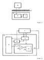
- FIG. 5 shows a medical implant 50, inserted under the skin 48, comprising a programmable control device 4 for control and coordination of the units in the implant 50 and a combined telemetry and magnetic field detector 52 with e.g. duplex communications with a programmer 56 placed on the exterior of the skin 48.
- FIG. 6 is a block diagram of the combined telemetry and magnetic field detector unit 52, henceforth referred to as the combined unit 52, according to a third preferred embodiment of the invention.
- the combined unit 52 comprises telemetry circuits 54 used for transmitting and receiving signals to and from the programmer 56 and for sensing magnetic fields, a magnetic field indicator 10 which detects the presence of a magnetic field, a telemetry signal circuit 58 for signals received by the telemetry circuits 54 and control logic 8 for controlling the telemetry circuits 54, the magnetic field indicator 10 and the telemetry signal circuit 58.
- the magnetic field indicator 10 comprises a voltage comparator 12 and a time measurement circuit 14 connected to the voltage comparator 12.
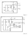
- FIG. 7 shows the telemetry circuits 54 according to the third preferred embodiment of the invention, the telemetry circuits comprising a source of voltage V+, a diode 16, a coil 18 with a core, a capacitor 60, a second resistor 62, a junction point 64 and a number of switches S1-S6.
- the switches S1-S6, which are controlled by the control logic 18 the components in the telemetry circuits 54 are enabled according to the function the telemetry circuits 54 is to have.
- the voltage V+ is connected via a switch S3 to the junction point 64.
- the diode 16 and the coil 18 are connected in parallel between the junction point 64 and the switch S1 which, in turn, is connected to ground.
- Diode 16 is connected via a switch S2 to the junction point 64.
- a measurement signal 20 is collected between the switch S1 and the coil 18 and diode 16, the latter two connected in parallel, and the measurement signal 20 is connected to the magnetic field indicator 10 via a switch S4.
- the capacitor 60 is connected to the junction point 64 and, via a switch S5, to ground.
- the second resistor 62 is connected to the junction point 64 and ground via a switch S6.
- the telemetry signal circuit 58 is connected to the junction point 64.
- the combined unit 52 senses at a defined interval, for example once a second, whether a magnetic field is present. When such a determination is made, the switches S2, S3 and S4 are closed whereas S5 and S6 are open. Determination of the presence of a magnetic field with a defined strength is performed in the same way as described in conjunction with the first preferred embodiment.
- the coil 18 is charged by the source of voltage V+ for a defined period of time 22. This is achieved when the switch S1 is closed during the defined period of time 22. Voltage across the coil during the defined period of time 22 is equal to the voltage V+.
- the switch S1 re-opens, the voltage drops, and the coil discharges through the diode 16.
- the voltage across the coil 18 is equal to minus the diode's voltage drop in the direction of conduction. After the discharge time 18, voltage returns to its normal level, i.e. there is no voltage across the coil. This return is performed in an oscillatory process.
- the measurement signal's 20 (lower curve in FIG. 4) potential is compared in the voltage comparator 12 in the magnetic field indicator 10 to an adjustable voltage threshold value 26.
- the coil's discharge time 24 is also measured in the magnetic field indicator 10, a detection signal 30 then being generated if the discharge time 24 is less than a defined time threshold value 32.
- the switches S2 and S4 are open and S1 is closed.
- S5 is closed, the capacitor 62 thus being connected to ground, whereas S6 is open, i.e. the second resistor 60 is not connected to ground.
- the coil 18 and the capacitor 60 form a resonance circuit which, with an appropriate choice of component values, has a preferred resonance frequency of 8 khz and a high Q value.
- Switch S3 opens and closes rapidly, so brief pulses are sent to the resonance circuit in which the coil 18 serves as the transmission antenna for the electromagnetic waves.
- the generated train of pulses comprises the information which is to be transferred to the programmer 56.
- the coil 18 picks up the signals transmitted by the programmer 56 and sends them, via the telemetry signal circuit 58, to the control device 4.
- the telemetry signal circuit 58 comprises e.g. a comparator circuit (not shown) in which the signal level for the received signal is compared to a defined threshold level, and only signals exceeding this level are processed.
- the second resistor 62 damps the signal so there is no residual voltage on the coil 18 at the start of transmission or reception.
- FIG. 8 shows a fourth preferred embodiment of the invention.
- This embodiment only differs from the above-described third embodiment in two respects. Firstly, the time period in which the switch S1 closes and the coil 18 charges is the same, as is the case for the second embodiment, as the time elapsing from the start of charging until the intensity of current through the coil 18 exceeds a defined level. This is achieved with a D flip-flop 36 and a comparator 38 in the same was as described in conjunction with the second preferred embodiment. Secondly, a switch S7 is connected across the resistor 34. This switch S7 is only closed during telemetry.
Description
- The present invention relates to a magnetic field detector and a medical implant comprising a combined telemetry and magnetic field detector unit.
- In a medical implant, e.g. a pacemaker, a magnetic field detector is used for non-invasive activation of different implant functions with the aid of e.g. a permanent magnet brought close to the implant on the outside of the patient's body. Some of the functions in e.g. a pacemaker which can be activated with a magnet are, for example: having the pacemaker disable the demand function so the pacemaker adapts its operation to the capacity of the battery, having the pacemaker operate according to a special, temporary stimulation mode in e.g. tachycardia, and in conjunction with pacemaker programming.
- A magnetic field detector intended for a medical implant should be small (the latest generation of pacemakers only weighs about 14 grams), insensitive to bumps and suit the assembly technique used for other components in the pacemaker.
- The detection of magnetic fields outside the implant art in a number of different ways is obviously generally known, e.g. with the aid of reed switches and Hall generators utilizing the Hall effect. The disadvantage of the Hall generator is its relatively heavy energy consumption.
- An electronic sensor for static magnetic fields is described in US-4 611 127. The sensor comprises a conventional resonance circuit consisting of e.g. a coil used to sense the presence of a magnetic field whose strength exceeds a defined value. The resonance frequency for the resonance circuit varies according to the strength of the magnetic field. The resonance circuit is activated periodically, and the number of zero crossings for the output signal from the resonance circuit is studied in a sensing window with a defined duration. If a given number of zero crossings occurs in the sensing window, this means that the strength of the magnetic field exceeds the defined value.
- A magnetic field detector of the conventional kind in the implant art consists of a reed switch. However, reed switches are relatively insensitive and rather expensive components which also take up a relatively large amount of space in the implant.
- To eliminate the need for a reed switch, therefore, utilization of the implant's telemetry unit even for detecting the presence of a magnetic field, in addition to performing telemetry functions, has been proposed in recent years.
- US-4 541 431 shows one such proposal with a combined telemetry and magnetic field detector in which magnetic field sensing is performed in the same way as described in US-4 611 127 cited above. The combined unit comprises a conventional resonance circuit consisting of e.g. a coil used in telemetry for transmitting and receiving data. The resonance circuit is also used here for sensing, in the above-described manner, the presence of a magnetic field whose strength exceeds a defined value.
- The object of the present invention is to achieve an improved device, employing fewer components than in the prior art, for detecting magnetic fields in general and for detecting magnetic fields near an implant in particular. This object is achieved with a magnetic field detector and a medical implant comprising a combined telemetry and magnetic field detector of the aforementioned type with the features set forth in
patent claims - The invention achieves magnetic field detection in which a detection signal is generated in the presence of magnetic fields.
- The invention utilizes the fact that the inductance of a coil with a core changes in the presence of a magnetic field, because the magnetic field affects the permeability of the core. When a voltage is applied to the coil for a specific period of time and the time it takes the coil to discharge through a diode is measured, the presence of a magnetic field with a defined strength can be detected. This is possible, since the coil discharge time is a function of the coil's inductance which changes in the presence of a magnetic field. Detection of the presence of a magnetic field is obtained when the discharge time is compared to a time threshold value corresponding to the presence of a magnetic field with a defined strength, and a detection signal is generated if the time is less than the threshold value.
- A first preferred embodiment of the invention relates to a magnetic field detector in which the coil's charging time is preset.
- A second preferred embodiment of the invention relates to a magnetic field detector in which the coil's charging time is the time elapsing from the start of charging until the intensity of current through the coil exceeds a preset value.
- A third preferred embodiment of the invention relates to a combined telemetry and magnetic field detector unit in which the coil's charging time is preset.
- A fourth embodiment of the invention relates to a telemetry and magnetic field detector in which the coil's charging time is the time elapsing from the start of charging until the intensity of current through the coil exceeds a preset value.
- The invention will now be described in greater detail, referring to the FIGURES in the attached drawings in which
- FIG. 1 is a schematic block diagram of a magnetic field detector according to the invention;
- FIG. 2 is a magnetic field sensor according to a first preferred embodiment;
- FIG. 3 is a magnetic field sensor according to a second preferred embodiment;
- FIG. 4 shows waveforms for voltage at two points in the magnetic field sensor;
- FIG. 5 is a block diagram of a medical implant and a programmer;
- FIG. 6 is a schematic block diagram of a medical implant according to the invention;
- FIG. 7 shows telemetry circuits according to a third preferred embodiment;
- FIG. 8 shows telemetry circuits according to a fourth preferred embodiment.
-
- In the FIGURES, the same reference designations are used for the same or similar elements.
- FIG. 1 shows a
magnetic field detector 2 connected to aprogrammable control device 4. Themagnetic field detector 2 comprises amagnetic field detector 6,control logic 8 and amagnetic field indicator 10. Themagnetic field detector 10 comprises avoltage comparator 12 and atime measurement circuit 14 connected to thevoltage comparator 12. - In FIG. 2 is shown a
magnetic field sensor 6 according to a first preferred embodiment. Themagnetic field sensor 6 has a source of voltage V+, adiode 16, acoil 18 with a core and a switch S1. The discharge means 16 and thecoil 18 are connected in parallel between the voltage V+ and the switch S1 which is connected, in turn, to ground. Ameasurement signal 20 is collected between the switch S1 andcoil 18 anddiode 16, the latter two connected in parallel. The opening and closing of the switch S1 are controlled by thecontrol logic 8. - FIG. 4 shows waveforms for voltage across the coil 18 (upper tracing) and for the measurement signal 20 (lower tracing). The vertical axis is for voltage in volts, and the horizontal axis is for time in µs.
- Referring to FIGURES 1, 2 and 4, the function of the
magnetic field detector 2 will now be described according to the first preferred embodiment. - In its normal state, the switch S1 is open. There is then no voltage across the
coil 18, and themeasurement signal 20 therefore has the same potential as the voltage V+. In a determination of the presence of a magnetic field with a defined strength, thecoil 18 is charged by the source of voltage V+ for a defined period of time (the coil's charging time) 22. This is achieved when the switch S1 is closed for the defined period of time 22. During the defined period of time 22, voltage across thecoil 18 is equal to the voltage V+. When the switch S1 re-opens, the voltage drops, and thecoil 18 discharges through thediode 16. During thisdischarge period 24, voltage across thecoil 18 is equal to minus the diode's 16 voltage drop in the conduction direction. After thedischarge time 24, voltage returns to its normal level, i.e. there is no voltage across thecoil 18. This return is performed in an oscillatory process. In measurement of the discharge time, the potential of the measurement signal 20 (the lower tracing in FIG. 4) is compared in thevoltage comparator 12 to an adjustablevoltage threshold value 26. Thevoltage comparator 12 generates avoltage signal 28 as long as the voltage exceeds thevoltage threshold value 26. Thisvoltage signal 28 is sent to thetime measurement circuit 14 which emits adetection signal 30 if the duration of thevoltage signal 28 is less than an adjustabletime threshold value 32. Thetime threshold value 32 is selected so the presence of a magnetic field with at least one defined strength is detected if the duration of thevoltage signal 28 is less than thetime threshold value 32. Thetime measurement circle 14 can be realized in a plurality of ways. According to one, the duration of thevoltage signal 28 is measured, and this time is then compared to thetime threshold value 32, whereupon thedetection signal 32 is generated if the duration of thevoltage signal 28 is less than thetime threshold value 32. Another way is to have a counter count as long as thevoltage signal 28 is present. If the count is interrupted before the counter reaches thetime threshold value 32, thedetection signal 30 is generated. - Typical values are 2.8 V for the voltage V+ and 0.7 V for the voltage drop across the diode. The short time in which the
coil 18 charges is on the order of some tens of microseconds, e.g. 30 µs. The coil's 18discharge time 24 is about 135-145 µs in the absence of a magnetic field and about 120-130 µs in the presence of a magnetic field. - An ordinary permanent magnet, placed at an appropriate distance from the magnetic field detector, is used to achieve a magnetic field with a defined strength. According to one application of the invention, the
magnetic field detector 2 is located in a medical implant. The magnet is then applied to the patient's exterior skin above the implant. The implant can be a pacemaker, for example. The pacemaker must then be able to detect a magnet from a distance up to 40 mm. - According to the above-described first preferred embodiment, the charging time of the coil is therefore predetermined.
- According to a second preferred embodiment, the time required for coil charging is the time elapsing from the start of charging until the intensity of current passing through the coil exceeds a preset level. This is achieved in a magnetic field sensor according to FIGURE 3.
- As in the first preferred embodiment, the
magnetic field sensor 6 according to this second preferred embodiment has a source of voltage V+, adiode 16, acoil 18 with a core and a switch S1. This second embodiment also comprises afirst resistor 34 connected between the switch S1 and ground, a D flip-flop 36 whose Q output terminal controls the switch S1 and acomparator 38 with oneinput terminal 40 connected to a reference voltage and oneinput terminal 42 connected between the switch S1 and thefirst resistor 34. The comparator's 38output terminal 44 is connected to the D flip-flop's 36 clock input terminal. - In a determination of the presence of a magnetic field with a defined strength, the
control logic 8 sends a pulse to the pre-set input terminal 46 on the D flip-flop, causing the output terminal Q to go high, thereby closing the switch S1 so charging of thecoil 18 starts. The coil continues to charge until the intensity of current through thecoil 18 exceeds a defined level. Since current through thecoil 18 is the same as the current through thefirst resistor 34, current intensity is determined by measuring the voltage across theresistor 34. When the potential above theresistor 34 but below the switch S1 exceeds thereference voltage 40, thecomparator 38 sends a clock signal to the D flip-flop, causing the potential on the D input terminal, i.e. the ground potential, to be clocked over to the Q output terminal, and the switch S1 opens. - The intensity of current through the
coil 18 is on the order of several hundred µA, e.g. 200-400 µA. The resistance of the first resistor is 500-1000 õ. This produces a discharge time for thecoil 18 of the same magnitude as in the first preferred embodiment. - Measurement of the duration of the
discharge time 16 is performed in the same way as for the first preferred embodiment. - According to the first and second embodiments, the
magnetic field detector 2 can be used for magnetic field detection in an implantable medical device which could be a pacemaker, a defibrillator, an insulin pump or some other medical device. - A third and fourth embodiment of the invention relates to a combined telemetry and magnetic field detector unit in a medical implant. Here, the implant could also consist of a pacemaker, a defibrillator, an insulin pump or some other medical device.
- FIG. 5 shows a
medical implant 50, inserted under theskin 48, comprising aprogrammable control device 4 for control and coordination of the units in theimplant 50 and a combined telemetry andmagnetic field detector 52 with e.g. duplex communications with aprogrammer 56 placed on the exterior of theskin 48. - FIG. 6 is a block diagram of the combined telemetry and magnetic
field detector unit 52, henceforth referred to as the combinedunit 52, according to a third preferred embodiment of the invention. - The combined
unit 52 comprisestelemetry circuits 54 used for transmitting and receiving signals to and from theprogrammer 56 and for sensing magnetic fields, amagnetic field indicator 10 which detects the presence of a magnetic field, atelemetry signal circuit 58 for signals received by thetelemetry circuits 54 andcontrol logic 8 for controlling thetelemetry circuits 54, themagnetic field indicator 10 and thetelemetry signal circuit 58. As in the first and second embodiments, themagnetic field indicator 10 comprises avoltage comparator 12 and atime measurement circuit 14 connected to thevoltage comparator 12. - FIG. 7 shows the
telemetry circuits 54 according to the third preferred embodiment of the invention, the telemetry circuits comprising a source of voltage V+, adiode 16, acoil 18 with a core, acapacitor 60, asecond resistor 62, ajunction point 64 and a number of switches S1-S6. With the aid of the switches S1-S6, which are controlled by thecontrol logic 18, the components in thetelemetry circuits 54 are enabled according to the function thetelemetry circuits 54 is to have. - The voltage V+ is connected via a switch S3 to the
junction point 64. Thediode 16 and thecoil 18 are connected in parallel between thejunction point 64 and the switch S1 which, in turn, is connected to ground.Diode 16 is connected via a switch S2 to thejunction point 64. Ameasurement signal 20 is collected between the switch S1 and thecoil 18 anddiode 16, the latter two connected in parallel, and themeasurement signal 20 is connected to themagnetic field indicator 10 via a switch S4. Thecapacitor 60 is connected to thejunction point 64 and, via a switch S5, to ground. Thesecond resistor 62 is connected to thejunction point 64 and ground via a switch S6. Thetelemetry signal circuit 58 is connected to thejunction point 64. - The combined
unit 52 senses at a defined interval, for example once a second, whether a magnetic field is present. When such a determination is made, the switches S2, S3 and S4 are closed whereas S5 and S6 are open. Determination of the presence of a magnetic field with a defined strength is performed in the same way as described in conjunction with the first preferred embodiment. Thus, thecoil 18 is charged by the source of voltage V+ for a defined period of time 22. This is achieved when the switch S1 is closed during the defined period of time 22. Voltage across the coil during the defined period of time 22 is equal to the voltage V+. When the switch S1 re-opens, the voltage drops, and the coil discharges through thediode 16. During thedischarge time 24, the voltage across thecoil 18 is equal to minus the diode's voltage drop in the direction of conduction. After thedischarge time 18, voltage returns to its normal level, i.e. there is no voltage across the coil. This return is performed in an oscillatory process. Whendischarge time 24 is measured, the measurement signal's 20 (lower curve in FIG. 4) potential is compared in thevoltage comparator 12 in themagnetic field indicator 10 to an adjustablevoltage threshold value 26. As previously noted, the coil'sdischarge time 24 is also measured in themagnetic field indicator 10, adetection signal 30 then being generated if thedischarge time 24 is less than a definedtime threshold value 32. - When the combined
unit 52 is to be used for telemetry, the switches S2 and S4 are open and S1 is closed. In transmission, S5 is closed, thecapacitor 62 thus being connected to ground, whereas S6 is open, i.e. thesecond resistor 60 is not connected to ground. Thecoil 18 and thecapacitor 60 form a resonance circuit which, with an appropriate choice of component values, has a preferred resonance frequency of 8 khz and a high Q value. Switch S3 opens and closes rapidly, so brief pulses are sent to the resonance circuit in which thecoil 18 serves as the transmission antenna for the electromagnetic waves. The generated train of pulses comprises the information which is to be transferred to theprogrammer 56. - When signals are received from the
programmer 56, S3 and S5 are open, whereas S6 is closed. Thecoil 18 picks up the signals transmitted by theprogrammer 56 and sends them, via thetelemetry signal circuit 58, to thecontrol device 4. Thetelemetry signal circuit 58 comprises e.g. a comparator circuit (not shown) in which the signal level for the received signal is compared to a defined threshold level, and only signals exceeding this level are processed. In reception, thesecond resistor 62 damps the signal so there is no residual voltage on thecoil 18 at the start of transmission or reception. - FIG. 8 shows a fourth preferred embodiment of the invention. This embodiment only differs from the above-described third embodiment in two respects. Firstly, the time period in which the switch S1 closes and the
coil 18 charges is the same, as is the case for the second embodiment, as the time elapsing from the start of charging until the intensity of current through thecoil 18 exceeds a defined level. This is achieved with a D flip-flop 36 and acomparator 38 in the same was as described in conjunction with the second preferred embodiment. Secondly, a switch S7 is connected across theresistor 34. This switch S7 is only closed during telemetry. - For the combined
unit 52 according to the third and fourth embodiments, no determination is made as to whether a magnetic field is present as long as telemetry transmission is in progress. When telemetry has been completed, magnetic field determination starts again, e.g. once a second. This control of the enablement of different functions is exercised by theprogrammable control device 4. -
- 1
- Magnetic field detector
- 4
- Programmable control device
- 6
- Magnetic field detector
- 8
- Control logic
- 10
- Magnetic field indicator
- 12
- Voltage comparator
- 14
- Time measurement circuit
- 16
- Diode
- 18
- Coil
- 20
- Measurement signal
- 22
- Charging time
- 24
- Discharge time
- 26
- Voltage threshold value
- 28
- Voltage signal
- 30
- Detection signal
- 32
- Time threshold value
- 34
- First resistor
- 36
- D flip-flop
- 38
- Comparator
- 40
- Reference voltage
- 42
- Comparator input terminal
- 44
- Comparator output terminal
- 46
- D flip-flop's pre-set input terminal
- 48
- The skin
- 50
- Medical implant
- 52
- Combined telemetry and magnetic field detector unit
- 54
- Telemetry circuits
- 56
- Programmer
- 58
- Telemetry signal circuit
- 60
- Capacitor
- 62
- Second resistor
- 64
- Junction point
- S1-S7
- Switches
- V+
- Voltage
Claims (6)
- A magnetic field detector (2) which has a magnetic field indicator (10) and a magnetic field sensor (6) comprising a source of voltage (V+) and a coil (18), characterized in that the magnetic field sensor (6) also comprises a diode (16), the coil (18) being charged by the source of voltage (V+) for a defined period of time (22) when the presence of a magnetic field is determined, and the magnetic field indicator (10) is arranged to measure the coil's discharge time (24) through the diode (16), the magnetic field indicator (10) generating a detection signal (30) for the presence of a magnetic field if this discharge time (24) is less than a defined time threshold value (32).
- A magnetic field detector (2) according to claim 1, characterized in that the defined time period (22) for the coil's (18) discharge is the time elapsing from the start of charging until the intensity of current through the coil (18) exceeds a defined value (40).
- Magnetic field detector (2) according to any of the preceding claims, characterized in that the magnetic field indicator (10) comprises a voltage comparator (12), which compares the voltage across the coil (18) to an adjustable voltage threshold value (26), and a time measurement circuit (14) holding the defined threshold value (32) for the coil's (18) discharge time (24), the voltage comparator (12) generating a voltage signal (28) as long as the voltage across the coil (18) exceeds the voltage threshold value (26), the voltage signal (28) thereafter being sent to the time measurement circuit (14) which emits the detection signal (30) if the voltage signal's (28) duration is less than the time threshold value (32).
- Magnetic field detector (2) according to any of the preceding claims, characterized in that said magnetic field detector (2) is arranged in a medical implant (50).
- Magnetic field detector (2) according to claim 4, characterized in that said magnetic field detector is included in a combined telemetry and magnetic field detector unit (52), the combined unit (52) comprising control logic (8), the magnetic field indicator (10) and a telemetry circuit (54) comprising the source of voltage (V+), a plurality of switches (S1-S7) and the coil (18), the control logic (8) being arranged to actuate the switches (S1-S7) so the combined unit (52) switches between telemetry and magnetic field detection, the coil (18) being used for transmitting telemetric signals to/from a programmer (56) and for magnetic field detection, respectively.
- Magnetic field detector (2) according to claim 5, characterized in that the telemetry circuit (54) comprises the diode (16) which is disconnected from the coil (18) during telemetry, the coil (18) being charged by the source of voltage (V+) for a defined period of time (22) in determinations of the presence of a magnetic field, and the magnetic field indicator (10) is arranged to measure the time for the coil's discharge (24) via the diode (16), the magnetic field indicator (10) then generating the detection signal (30) for the presence of a magnetic field if this discharge time (24) is less than the defined time threshold value (32).
Applications Claiming Priority (2)
| Application Number | Priority Date | Filing Date | Title |
|---|---|---|---|
| SE9404374 | 1994-12-15 | ||
| SE9404374A SE9404374D0 (en) | 1994-12-15 | 1994-12-15 | magnetic field detector |
Publications (2)
| Publication Number | Publication Date |
|---|---|
| EP0718010A1 EP0718010A1 (en) | 1996-06-26 |
| EP0718010B1 true EP0718010B1 (en) | 2003-02-19 |
Family
ID=20396354
Family Applications (1)
| Application Number | Title | Priority Date | Filing Date |
|---|---|---|---|
| EP95118518A Expired - Lifetime EP0718010B1 (en) | 1994-12-15 | 1995-11-24 | Magnetic field detector unit |
Country Status (5)
| Country | Link |
|---|---|
| US (2) | US5662694A (en) |
| EP (1) | EP0718010B1 (en) |
| JP (1) | JPH08215323A (en) |
| DE (1) | DE69529662T2 (en) |
| SE (1) | SE9404374D0 (en) |
Families Citing this family (91)
| Publication number | Priority date | Publication date | Assignee | Title |
|---|---|---|---|---|
| US5797879A (en) * | 1996-08-26 | 1998-08-25 | Decampli; William M. | Apparatus and methods for providing selectively adjustable blood flow through a vascular graft |
| US5831513A (en) * | 1997-02-04 | 1998-11-03 | United Microelectronics Corp. | Magnetic field sensing device |
| US6208894B1 (en) | 1997-02-26 | 2001-03-27 | Alfred E. Mann Foundation For Scientific Research And Advanced Bionics | System of implantable devices for monitoring and/or affecting body parameters |
| US6164284A (en) * | 1997-02-26 | 2000-12-26 | Schulman; Joseph H. | System of implantable devices for monitoring and/or affecting body parameters |
| US7114502B2 (en) * | 1997-02-26 | 2006-10-03 | Alfred E. Mann Foundation For Scientific Research | Battery-powered patient implantable device |
| WO1998043701A1 (en) * | 1997-03-27 | 1998-10-08 | Alfred E. Mann Foundation For Scientific Research | System of implantable devices for monitoring and/or affecting body parameters |
| US6084406A (en) * | 1997-04-01 | 2000-07-04 | Precision Navigation, Inc. | Half-cycle saturable-core magnetometer circuit |
| US5998980A (en) * | 1998-04-16 | 1999-12-07 | Microchip Technology Incorporated | Highly efficient multi-frequency voltage regulating circuit incorporating a magnetic field power sensor and programmable magnetic field detection |
| US5873733A (en) * | 1998-01-23 | 1999-02-23 | Sulzer Intermedics Inc. | Training unit for the pacemaker emergency intervention system using magnetic entry code |
| US8465425B2 (en) | 1998-04-30 | 2013-06-18 | Abbott Diabetes Care Inc. | Analyte monitoring device and methods of use |
| US8688188B2 (en) | 1998-04-30 | 2014-04-01 | Abbott Diabetes Care Inc. | Analyte monitoring device and methods of use |
| US8346337B2 (en) | 1998-04-30 | 2013-01-01 | Abbott Diabetes Care Inc. | Analyte monitoring device and methods of use |
| US9066695B2 (en) | 1998-04-30 | 2015-06-30 | Abbott Diabetes Care Inc. | Analyte monitoring device and methods of use |
| US6175752B1 (en) | 1998-04-30 | 2001-01-16 | Therasense, Inc. | Analyte monitoring device and methods of use |
| US8974386B2 (en) | 1998-04-30 | 2015-03-10 | Abbott Diabetes Care Inc. | Analyte monitoring device and methods of use |
| US6949816B2 (en) | 2003-04-21 | 2005-09-27 | Motorola, Inc. | Semiconductor component having first surface area for electrically coupling to a semiconductor chip and second surface area for electrically coupling to a substrate, and method of manufacturing same |
| US8480580B2 (en) | 1998-04-30 | 2013-07-09 | Abbott Diabetes Care Inc. | Analyte monitoring device and methods of use |
| US6101417A (en) * | 1998-05-12 | 2000-08-08 | Pacesetter, Inc. | Implantable electrical device incorporating a magnetoresistive magnetic field sensor |
| US6287253B1 (en) * | 1999-06-25 | 2001-09-11 | Sabolich Research & Development | Pressure ulcer condition sensing and monitoring |
| US6580947B1 (en) | 2000-03-10 | 2003-06-17 | Medtronic, Inc. | Magnetic field sensor for an implantable medical device |
| FR2806808B1 (en) * | 2000-03-24 | 2002-05-24 | Ela Medical Sa | CIRCUIT FOR DETECTING THE PRESENCE OF A PERMANENT MAGNET IN THE VICINITY OF AN ACTIVE MEDICAL DEVICE, IN PARTICULAR A CARDIAC PACEMAKER, DEFIBRILLATOR, CARDIOVERTER AND/OR MULTI-SITE DEVICE |
| US6560471B1 (en) | 2001-01-02 | 2003-05-06 | Therasense, Inc. | Analyte monitoring device and methods of use |
| EP1397068A2 (en) | 2001-04-02 | 2004-03-17 | Therasense, Inc. | Blood glucose tracking apparatus and methods |
| DE10136642A1 (en) * | 2001-07-20 | 2003-02-06 | Biotronik Mess & Therapieg | Disposable medical device |
| US7729776B2 (en) | 2001-12-19 | 2010-06-01 | Cardiac Pacemakers, Inc. | Implantable medical device with two or more telemetry systems |
| US6993393B2 (en) | 2001-12-19 | 2006-01-31 | Cardiac Pacemakers, Inc. | Telemetry duty cycle management system for an implantable medical device |
| US6937906B2 (en) * | 2002-01-29 | 2005-08-30 | Medtronic, Inc. | Method and apparatus for detecting static magnetic fields |
| US7050855B2 (en) * | 2002-01-29 | 2006-05-23 | Medtronic, Inc. | Medical implantable system for reducing magnetic resonance effects |
| US7082328B2 (en) | 2002-01-29 | 2006-07-25 | Medtronic, Inc. | Methods and apparatus for controlling a pacing system in the presence of EMI |
| US6985773B2 (en) | 2002-02-07 | 2006-01-10 | Cardiac Pacemakers, Inc. | Methods and apparatuses for implantable medical device telemetry power management |
| US7024249B2 (en) * | 2002-02-21 | 2006-04-04 | Alfred E. Mann Foundation For Scientific Research | Pulsed magnetic control system for interlocking functions of battery powered living tissue stimulators |
| US8111165B2 (en) | 2002-10-02 | 2012-02-07 | Orthocare Innovations Llc | Active on-patient sensor, method and system |
| US7242981B2 (en) * | 2003-06-30 | 2007-07-10 | Codman Neuro Sciences Sárl | System and method for controlling an implantable medical device subject to magnetic field or radio frequency exposure |
| US7231251B2 (en) * | 2003-08-14 | 2007-06-12 | Cardiac Pacemakers, Inc. | EMI detection for implantable medical devices |
| US8332011B2 (en) * | 2003-09-29 | 2012-12-11 | Medtronic, Inc. | Controlling blanking during magnetic resonance imaging |
| US7450998B2 (en) | 2003-11-21 | 2008-11-11 | Alfred E. Mann Foundation For Scientific Research | Method of placing an implantable device proximate to neural/muscular tissue |
| US7228182B2 (en) * | 2004-03-15 | 2007-06-05 | Cardiac Pacemakers, Inc. | Cryptographic authentication for telemetry with an implantable medical device |
| WO2005099817A1 (en) | 2004-04-07 | 2005-10-27 | Cardiac Pacemakers, Inc. | Rf wake-up of implantable medical device |
| US7794499B2 (en) | 2004-06-08 | 2010-09-14 | Theken Disc, L.L.C. | Prosthetic intervertebral spinal disc with integral microprocessor |
| US7890180B2 (en) * | 2004-08-09 | 2011-02-15 | Cardiac Pacemakers, Inc. | Secure remote access for an implantable medical device |
| US7539541B2 (en) | 2004-08-09 | 2009-05-26 | Cardiac Pacemakers, Inc. | Automatic power control for a radio frequency transceiver of an implantable device |
| US7881802B2 (en) * | 2004-08-09 | 2011-02-01 | Cardiac Pacemakers, Inc. | Telemetry switchover state machine with firmware priority control |
| US7406349B2 (en) * | 2004-08-09 | 2008-07-29 | Cardiac Pacemakers, Inc. | Dynamic telemetry link selection for an implantable device |
| US8014867B2 (en) | 2004-12-17 | 2011-09-06 | Cardiac Pacemakers, Inc. | MRI operation modes for implantable medical devices |
| US7561915B1 (en) | 2004-12-17 | 2009-07-14 | Cardiac Pacemakers, Inc. | MRI system having implantable device safety features |
| US7369898B1 (en) * | 2004-12-22 | 2008-05-06 | Pacesetter, Inc. | System and method for responding to pulsed gradient magnetic fields using an implantable medical device |
| US7218969B2 (en) * | 2005-01-19 | 2007-05-15 | Cardiac Pacemakers, Inc. | Dynamic channel selection for RF telemetry with implantable device |
| US20060173295A1 (en) * | 2005-01-26 | 2006-08-03 | Zeijlemaker Volkert A | Apparatus for detecting strong magnetic fields for protection of medical devices |
| US7610065B2 (en) | 2005-02-28 | 2009-10-27 | Cardiac Pacemakers, Inc. | Method and apparatus for antenna selection in a diversity antenna system for communicating with implantable medical device |
| US7868779B2 (en) * | 2005-04-04 | 2011-01-11 | Codman NeuroSciences Sárl | Circuitry for powering on and maintaining activation of a powered off electronic component |
| US7664553B2 (en) | 2005-04-27 | 2010-02-16 | Cardiac Pacemakers, Inc. | System and method for enabling communications with implantable medical devices |
| EP2471452B1 (en) | 2005-10-14 | 2014-12-10 | Pacesetter, Inc. | Cardiac pacing system and method of conveying information therein |
| US9168383B2 (en) | 2005-10-14 | 2015-10-27 | Pacesetter, Inc. | Leadless cardiac pacemaker with conducted communication |
| US7383734B2 (en) * | 2006-01-31 | 2008-06-10 | Medtronic, Inc. | Simulation of magnetic field induced vibrations in implantable medical devices |
| US7509167B2 (en) | 2006-02-16 | 2009-03-24 | Cardiac Pacemakers, Inc. | MRI detector for implantable medical device |
| US7693568B2 (en) | 2006-03-30 | 2010-04-06 | Medtronic, Inc. | Medical device sensing and detection during MRI |
| US9549688B2 (en) * | 2006-04-24 | 2017-01-24 | Medtronic, Inc. | Implantable medical device detection |
| US8805526B2 (en) | 2006-05-03 | 2014-08-12 | Cardiac Pacemakers, Inc. | Configurable medical telemetry radio system |
| US7920907B2 (en) | 2006-06-07 | 2011-04-05 | Abbott Diabetes Care Inc. | Analyte monitoring system and method |
| US8185204B2 (en) | 2006-07-12 | 2012-05-22 | Cardiac Pacemakers, Inc. | Implantable medical device telemetry with adaptive frequency hopping |
| US9399130B2 (en) | 2007-04-25 | 2016-07-26 | Medtronic, Inc. | Cannula configured to deliver test stimulation |
| US9561053B2 (en) | 2007-04-25 | 2017-02-07 | Medtronic, Inc. | Implant tool to facilitate medical device implantation |
| US8032228B2 (en) | 2007-12-06 | 2011-10-04 | Cardiac Pacemakers, Inc. | Method and apparatus for disconnecting the tip electrode during MRI |
| US8086321B2 (en) | 2007-12-06 | 2011-12-27 | Cardiac Pacemakers, Inc. | Selectively connecting the tip electrode during therapy for MRI shielding |
| JP2011505964A (en) | 2007-12-12 | 2011-03-03 | カーディアック ペースメイカーズ, インコーポレイテッド | Implantable medical device with Hall sensor |
| US8311637B2 (en) | 2008-02-11 | 2012-11-13 | Cardiac Pacemakers, Inc. | Magnetic core flux canceling of ferrites in MRI |
| US8160717B2 (en) | 2008-02-19 | 2012-04-17 | Cardiac Pacemakers, Inc. | Model reference identification and cancellation of magnetically-induced voltages in a gradient magnetic field |
| US7755349B2 (en) * | 2008-03-03 | 2010-07-13 | Memsic, Inc. | Correcting offset in magneto-resistive devices |
| US8571661B2 (en) | 2008-10-02 | 2013-10-29 | Cardiac Pacemakers, Inc. | Implantable medical device responsive to MRI induced capture threshold changes |
| WO2010088687A1 (en) | 2009-02-02 | 2010-08-05 | Nanostim, Inc. | Leadless cardiac pacemaker with secondary fixation capability |
| EP2398553B1 (en) | 2009-02-19 | 2015-07-22 | Cardiac Pacemakers, Inc. | Systems for providing arrhythmia therapy in mri environments |
| EP2509682B1 (en) * | 2009-12-08 | 2015-01-14 | Cardiac Pacemakers, Inc. | Implantable medical device with automatic tachycardia detection and control in mri environments |
| US9919158B2 (en) | 2009-12-29 | 2018-03-20 | Medtronic, Inc. | Configuring operating parameters of a medical device based on exposure to a disruptive energy field |
| US8391992B2 (en) | 2009-12-30 | 2013-03-05 | Cardiac Pacemakers, Inc. | Implantable medical device switching power supply including multiple modes |
| EP2627403A4 (en) | 2010-10-12 | 2014-03-26 | Nanostim Inc | Temperature sensor for a leadless cardiac pacemaker |
| WO2012051235A1 (en) | 2010-10-13 | 2012-04-19 | Nanostim, Inc. | Leadless cardiac pacemaker with anti-unscrewing feature |
| US8744578B2 (en) * | 2010-10-29 | 2014-06-03 | Medtronic, Inc. | Staged sensing adjustments by an implantable medical device in the presence of interfering signals |
| US8983606B2 (en) | 2010-10-29 | 2015-03-17 | Medtronic, Inc. | Enhanced sensing by an implantable medical device in the presence of an interfering signal from an external source |
| EP2651502B1 (en) | 2010-12-13 | 2016-11-09 | Pacesetter, Inc. | Pacemaker retrieval systems |
| EP2651494B1 (en) | 2010-12-13 | 2017-02-15 | Pacesetter, Inc. | Delivery catheter |
| EP2654889B1 (en) | 2010-12-20 | 2017-03-01 | Pacesetter, Inc. | Leadless pacemaker with radial fixation mechanism |
| US10391320B2 (en) | 2011-01-28 | 2019-08-27 | Medtronic, Inc. | Techniques for detecting magnetic resonance imaging field |
| US9950179B2 (en) * | 2011-10-28 | 2018-04-24 | Medtronic, Inc. | Medical devices for trial stimulation |
| WO2013067496A2 (en) | 2011-11-04 | 2013-05-10 | Nanostim, Inc. | Leadless cardiac pacemaker with integral battery and redundant welds |
| US8971989B2 (en) | 2012-01-24 | 2015-03-03 | Covidien Lp | Magnetic field device for mapping and navigation in laparoscopic surgery |
| US9283397B2 (en) | 2012-01-31 | 2016-03-15 | Christopher C. Stancer | Charge control for high voltage therapy energy storage component |
| US9630018B2 (en) | 2012-01-31 | 2017-04-25 | Medtronic, Inc. | Charge control for high voltage therapy energy storage component |
| US9981124B2 (en) | 2012-04-26 | 2018-05-29 | Medtronic, Inc. | Devices and techniques for detecting magnetic resonance imaging field |
| EP2879758B1 (en) | 2012-08-01 | 2018-04-18 | Pacesetter, Inc. | Biostimulator circuit with flying cell |
| US9641012B2 (en) | 2014-04-18 | 2017-05-02 | Medtronic, Inc. | Methods, implantable medical devices, and systems that abort a high voltage charge when a transformer is impaired |
| US11819285B2 (en) | 2019-04-05 | 2023-11-21 | Covidien Lp | Magnetic interference detection systems and methods |
Family Cites Families (6)
| Publication number | Priority date | Publication date | Assignee | Title |
|---|---|---|---|---|
| US3659591A (en) * | 1970-08-24 | 1972-05-02 | Doll Research | Electromagnetic flowmeter |
| US4541431A (en) * | 1984-09-20 | 1985-09-17 | Telectronics Pty. Ltd. | Use of telemetry coil to replace magnetically activated reed switch in implantable devices |
| US4611127A (en) * | 1984-09-20 | 1986-09-09 | Telectronics N.V. | Electronic sensor for static magnetic field |
| DE3525070A1 (en) * | 1985-07-13 | 1987-01-22 | Honeywell Regelsysteme Gmbh | Magnetic field sensor |
| AU5597194A (en) * | 1992-11-24 | 1994-06-22 | Medtronic, Inc. | Implantable medical device with magnetically actuated switch |
| SE9400622D0 (en) * | 1994-02-23 | 1994-02-23 | Siemens Elema Ab | Medical implant |
-
1994
- 1994-12-15 SE SE9404374A patent/SE9404374D0/en not_active Application Discontinuation
-
1995
- 1995-11-24 EP EP95118518A patent/EP0718010B1/en not_active Expired - Lifetime
- 1995-11-24 DE DE69529662T patent/DE69529662T2/en not_active Expired - Fee Related
- 1995-12-14 US US08/572,068 patent/US5662694A/en not_active Expired - Fee Related
- 1995-12-15 JP JP7327337A patent/JPH08215323A/en active Pending
-
1996
- 1996-12-20 US US08/771,151 patent/US5694952A/en not_active Expired - Fee Related
Also Published As
| Publication number | Publication date |
|---|---|
| EP0718010A1 (en) | 1996-06-26 |
| US5694952A (en) | 1997-12-09 |
| US5662694A (en) | 1997-09-02 |
| DE69529662T2 (en) | 2003-10-16 |
| DE69529662D1 (en) | 2003-03-27 |
| SE9404374D0 (en) | 1994-12-15 |
| JPH08215323A (en) | 1996-08-27 |
Similar Documents
| Publication | Publication Date | Title |
|---|---|---|
| EP0718010B1 (en) | Magnetic field detector unit | |
| EP0702981B1 (en) | Magnetic field detector in a medical implant | |
| EP0670170B1 (en) | Combined telemetry and magnetic field detector unit for a medical implant | |
| US6473652B1 (en) | Method and apparatus for locating implanted receiver and feedback regulation between subcutaneous and external coils | |
| EP2764891B1 (en) | Implantable stimulation device, stimulation system and method for data communication | |
| US4541431A (en) | Use of telemetry coil to replace magnetically activated reed switch in implantable devices | |
| EP0931566B1 (en) | Interference detecting pacemaker | |
| US4571589A (en) | Biomedical implant with high speed, low power two-way telemetry | |
| EP0089014B1 (en) | Physiological implantable cardiac pacemaker in which the stimulation rate is regulated by the respiration rate of the patient | |
| US5697958A (en) | Electromagnetic noise detector for implantable medical devices | |
| US20160279430A1 (en) | Implantable stimulation device, stimulation system and method for data communication | |
| CA1335114C (en) | Method and apparatus for assuring pacer programming is compatible with the lead | |
| EP0972540A2 (en) | Implantable stimulator with battery status measurement | |
| EP0011937A2 (en) | Implantable cardiac pacemaker pulse generator | |
| US8554300B2 (en) | MRI gradient field detector | |
| US6487452B2 (en) | Circuit for detection of the presence of a permanent magnet in the vicinity of an active medical device, in particular a pacemaker, defibrillator, cardiovertor and/or multisite device | |
| US4099530A (en) | Cardiac pacer circuitry to facilitate testing of patient heart activity and pacer pulses | |
| EP0011939A2 (en) | Digital cardiac pacemaker pulse generator | |
| US10537742B2 (en) | System and methods for capture verification in implantable leadless pacemakers | |
| EP0011941B1 (en) | Demand cardiac pacemaker pulse generator | |
| US3898995A (en) | Noncompetitive pacemaker with programmable unijunction transistors | |
| EP3669935A1 (en) | Capacitor-discharge communication scheme for an implantable medical system | |
| US6304781B1 (en) | Electrostimulator | |
| EP0011936B1 (en) | Implantable programmable electromedical device | |
| EP0011949B1 (en) | Body tissue stimulator pulse generator |
Legal Events
| Date | Code | Title | Description |
|---|---|---|---|
| PUAI | Public reference made under article 153(3) epc to a published international application that has entered the european phase |
Free format text: ORIGINAL CODE: 0009012 |
|
| AK | Designated contracting states |
Kind code of ref document: A1 Designated state(s): DE ES FR GB IT |
|
| 17P | Request for examination filed |
Effective date: 19961227 |
|
| RAP1 | Party data changed (applicant data changed or rights of an application transferred) |
Owner name: ST. JUDE MEDICAL AB |
|
| 17Q | First examination report despatched |
Effective date: 20011029 |
|
| GRAG | Despatch of communication of intention to grant |
Free format text: ORIGINAL CODE: EPIDOS AGRA |
|
| RTI1 | Title (correction) |
Free format text: MAGNETIC FIELD DETECTOR UNIT |
|
| GRAG | Despatch of communication of intention to grant |
Free format text: ORIGINAL CODE: EPIDOS AGRA |
|
| GRAH | Despatch of communication of intention to grant a patent |
Free format text: ORIGINAL CODE: EPIDOS IGRA |
|
| GRAH | Despatch of communication of intention to grant a patent |
Free format text: ORIGINAL CODE: EPIDOS IGRA |
|
| GRAA | (expected) grant |
Free format text: ORIGINAL CODE: 0009210 |
|
| AK | Designated contracting states |
Designated state(s): DE ES FR GB IT |
|
| REG | Reference to a national code |
Ref country code: GB Ref legal event code: FG4D |
|
| REF | Corresponds to: |
Ref document number: 69529662 Country of ref document: DE Date of ref document: 20030327 Kind code of ref document: P |
|
| PG25 | Lapsed in a contracting state [announced via postgrant information from national office to epo] |
Ref country code: ES Free format text: LAPSE BECAUSE OF FAILURE TO SUBMIT A TRANSLATION OF THE DESCRIPTION OR TO PAY THE FEE WITHIN THE PRESCRIBED TIME-LIMIT Effective date: 20030828 |
|
| ET | Fr: translation filed | ||
| PG25 | Lapsed in a contracting state [announced via postgrant information from national office to epo] |
Ref country code: GB Free format text: LAPSE BECAUSE OF NON-PAYMENT OF DUE FEES Effective date: 20031124 |
|
| PLBE | No opposition filed within time limit |
Free format text: ORIGINAL CODE: 0009261 |
|
| STAA | Information on the status of an ep patent application or granted ep patent |
Free format text: STATUS: NO OPPOSITION FILED WITHIN TIME LIMIT |
|
| 26N | No opposition filed |
Effective date: 20031120 |
|
| GBPC | Gb: european patent ceased through non-payment of renewal fee |
Effective date: 20031124 |
|
| PGFP | Annual fee paid to national office [announced via postgrant information from national office to epo] |
Ref country code: FR Payment date: 20061031 Year of fee payment: 12 |
|
| PGFP | Annual fee paid to national office [announced via postgrant information from national office to epo] |
Ref country code: DE Payment date: 20061124 Year of fee payment: 12 |
|
| PGFP | Annual fee paid to national office [announced via postgrant information from national office to epo] |
Ref country code: IT Payment date: 20061130 Year of fee payment: 12 |
|
| PG25 | Lapsed in a contracting state [announced via postgrant information from national office to epo] |
Ref country code: DE Free format text: LAPSE BECAUSE OF NON-PAYMENT OF DUE FEES Effective date: 20080603 |
|
| REG | Reference to a national code |
Ref country code: FR Ref legal event code: ST Effective date: 20080930 |
|
| PG25 | Lapsed in a contracting state [announced via postgrant information from national office to epo] |
Ref country code: FR Free format text: LAPSE BECAUSE OF NON-PAYMENT OF DUE FEES Effective date: 20071130 |
|
| PG25 | Lapsed in a contracting state [announced via postgrant information from national office to epo] |
Ref country code: IT Free format text: LAPSE BECAUSE OF NON-PAYMENT OF DUE FEES Effective date: 20071124 |