EP0720004B1 - FDIC-Verfahren zur Minimierung von Messfehlern in einer Messanordnung von redundanten Sensoren - Google Patents
FDIC-Verfahren zur Minimierung von Messfehlern in einer Messanordnung von redundanten Sensoren Download PDFInfo
- Publication number
- EP0720004B1 EP0720004B1 EP95117943A EP95117943A EP0720004B1 EP 0720004 B1 EP0720004 B1 EP 0720004B1 EP 95117943 A EP95117943 A EP 95117943A EP 95117943 A EP95117943 A EP 95117943A EP 0720004 B1 EP0720004 B1 EP 0720004B1
- Authority
- EP
- European Patent Office
- Prior art keywords
- sensors
- error
- parity
- sensor
- vector
- Prior art date
- Legal status (The legal status is an assumption and is not a legal conclusion. Google has not performed a legal analysis and makes no representation as to the accuracy of the status listed.)
- Expired - Lifetime
Links
- 238000000034 method Methods 0.000 title claims description 56
- 238000005259 measurement Methods 0.000 title claims description 28
- 239000013598 vector Substances 0.000 claims description 62
- 238000002955 isolation Methods 0.000 claims description 29
- 238000001514 detection method Methods 0.000 claims description 22
- 238000012545 processing Methods 0.000 claims description 10
- 230000009466 transformation Effects 0.000 claims description 8
- 230000002950 deficient Effects 0.000 claims description 6
- 239000011159 matrix material Substances 0.000 description 16
- 238000007476 Maximum Likelihood Methods 0.000 description 6
- 238000004364 calculation method Methods 0.000 description 5
- 238000004458 analytical method Methods 0.000 description 3
- 238000009413 insulation Methods 0.000 description 3
- 230000003044 adaptive effect Effects 0.000 description 2
- 238000012512 characterization method Methods 0.000 description 2
- 241001136792 Alle Species 0.000 description 1
- 230000001133 acceleration Effects 0.000 description 1
- 230000006978 adaptation Effects 0.000 description 1
- 238000007792 addition Methods 0.000 description 1
- 238000012937 correction Methods 0.000 description 1
- 238000000354 decomposition reaction Methods 0.000 description 1
- 230000007850 degeneration Effects 0.000 description 1
- 230000001419 dependent effect Effects 0.000 description 1
- 238000011161 development Methods 0.000 description 1
- 230000018109 developmental process Effects 0.000 description 1
- 238000010586 diagram Methods 0.000 description 1
- 230000004069 differentiation Effects 0.000 description 1
- 238000011156 evaluation Methods 0.000 description 1
- 230000035876 healing Effects 0.000 description 1
- 230000004807 localization Effects 0.000 description 1
- 238000013139 quantization Methods 0.000 description 1
- 230000035945 sensitivity Effects 0.000 description 1
- 238000012360 testing method Methods 0.000 description 1
- 238000010200 validation analysis Methods 0.000 description 1
Images


Classifications
-
- G—PHYSICS
- G01—MEASURING; TESTING
- G01D—MEASURING NOT SPECIALLY ADAPTED FOR A SPECIFIC VARIABLE; ARRANGEMENTS FOR MEASURING TWO OR MORE VARIABLES NOT COVERED IN A SINGLE OTHER SUBCLASS; TARIFF METERING APPARATUS; MEASURING OR TESTING NOT OTHERWISE PROVIDED FOR
- G01D3/00—Indicating or recording apparatus with provision for the special purposes referred to in the subgroups
- G01D3/08—Indicating or recording apparatus with provision for the special purposes referred to in the subgroups with provision for safeguarding the apparatus, e.g. against abnormal operation, against breakdown
Definitions
- the invention relates to a method for minimizing measured variables determined from sensors with possible measurement errors, which are detected via a plurality of such redundant sensors connected to form a measurement arrangement, by recognizing and isolating the faulty sensors.
- redundant sensors are available for measuring a measurand to be determined.
- individual errors can be compared by comparing the data supplied by the sensors or several sensors can be recognized. If additionally the faulty sensors can be isolated by omitting the sensors identified as defective Measurement errors can be eliminated.
- EP-A-0 416 370 describes a method for minimizing derived from sensors with possible measurement errors Measured variables described in which from measured values Parity vector is formed. The amount of this parity vector is used as a measure of the presence of a measurement error exploited, whereby from a measuring arrangement or "measuring matrix” characteristic vectors, so-called “validation vectors" be formed.
- DE-A-41 00 501 describes a method for recognition known errors in sensors for state variables, considering the time-variant, stochastic Errors whose statistical properties are not known error detection and localization are possible is.
- the invention is therefore based on the object of an improved Introduce FDIC procedure that is free of the listed disadvantages of the prior art, the in parity procedures or maximum likelihood procedures surrender.
- the principle of the method is that by projecting the measured parity vector on all possible subspaces, which of the subspaces is assigned to each Error level (one-axis, two-axis, ...) the largest proportion of the measured parity vector includes. By omitting the sensor combinations belonging to these subspaces the best sensor combination can then be determined at every error level. The result this fault isolation is independent of any threshold values, since it is not from the Amount (length) of the measured parity vector, but solely by its direction is determined.
- the amount of the parity vector or the projection of the parity vector the subspaces are only used for error detection, that is to say decide whether there is an error at all, or whether a single, double, triple error, ..., must be accepted. (This decision can also be made without "a priori" threshold values to be taken if you optionally have the projections on the subspaces with minimal Uses redundancy as a measure of these threshold values.)
- the basis of the method is based on a linear or linearized relationship between the variables to be determined and the sensor values measured in the fault-free case.
- s A x + e where s characterize the sensor values combined into measurement vectors, x the quantity to be measured and e the sensor error.
- the matrix A describes the relationship between the two for the error-free case.
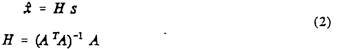
- the estimated value for the quantity to be measured results from measured sensor values in accordance with where H, as the pseudo inverse of matrix A, supplies the linear least-squares fit, and it is further assumed that the inverse that occurs exists, that is to say that the measured variable can be determined at all.
- the size of the residual vector r is a measure of the consistency of the sensor data in such a way that r is zero in the case of completely consistent sensor data, whereas r is different from zero in the case of faulty sensor data and in principle allows conclusions to be drawn about the error.
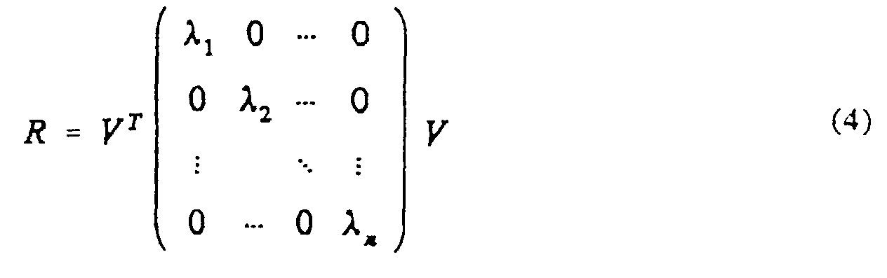
- r is used directly, but first of all according to R diagonalized.
- R is real and symmetrical, so that this diagonalization is always possible. It also applies to the eigenvalues ⁇ i that they can only assume the values 0 and 1, the degeneracy of the eigenvalue 0 being determined by the dimension of the measured variable and the degeneration of the eigenvalue 1 by the number of redundant sensors.
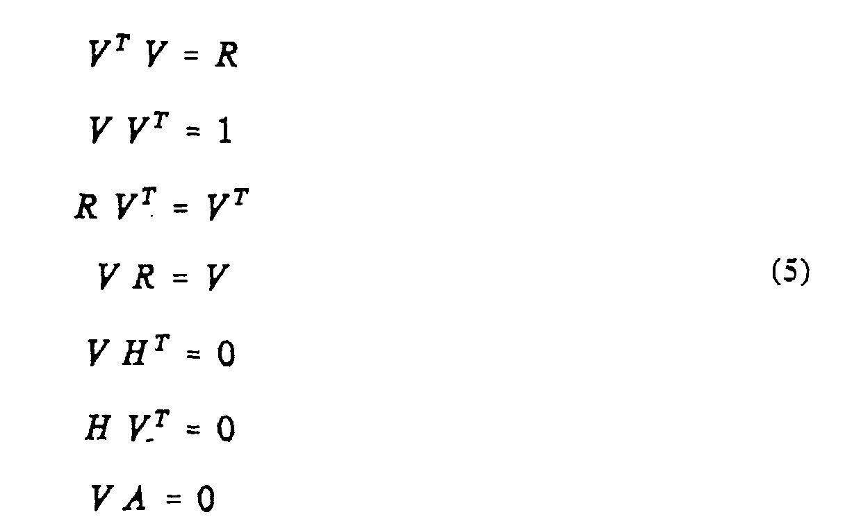
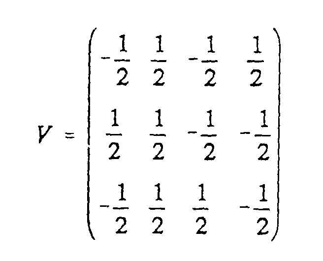
- the matrix V has the following properties
- the image p V p defines a parity vector p for a measurement vector s, in which all information about the error state of the sensor values is contained.
- r T r p T p that is, the length of the residual vector r is equal to the length of the parity vector p and serves as a measure of the consistency of the sensor combination that includes all sensors.
- the parity vector determined according to (6) will lie completely in the direction defined by the i th column of V.
- the resulting parity vector lies in the plane spanned by the i- th and j- th column of V.
- the column vectors of the matrix V therefore each define, for certain error combinations, characteristic subspaces in which the resulting parity vector is contained.
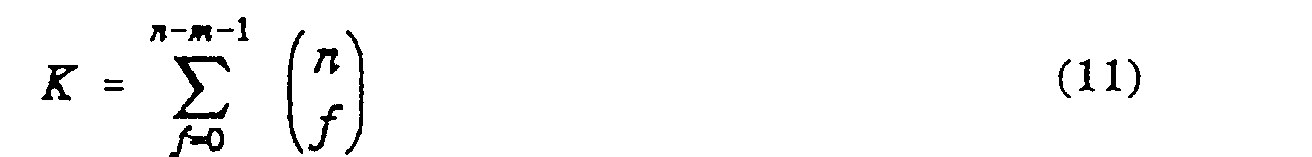
- the parity space has the dimension ( nm ) and the matrix V consists of n characteristic column vectors.
- the parity space can only be completely spanned by ( nm ) column vectors, which means that errors in up to ( nm -1) sensors can be isolated in this way.
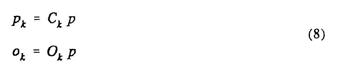
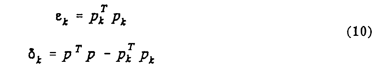
- the sizes are a measure of what proportion of the observed inconsistency results from the sensors involved in the combination k , or remains if these sensors are omitted.
- the consistency of the remaining sensors can be determined in accordance with (8), and a decision can be made by comparison with a threshold value that depends on the error level as to whether the remaining sensor combination offers acceptable consistency.
- the sensor combination can also be sorted in order of increasing inconsistency at each error level, and the combination with the best consistency can be determined for each error level.
- parity vector An important property of the parity vector, which is used in the practical implementation of the method, is that the relative sizes of the inconsistencies for the different sensor combinations are determined solely by the orientation of the parity vector in the parity space.
- the absolute size is given by a common factor from the amount of the parity vector. However, this has no influence on the order of the sensor combinations sorted according to inconsistencies.
- threshold values As acceptance criteria for the inconsistencies the remaining sensor combinations at the different error levels, in the following also referred to as “threshold values", it must be taken into account that also fault-free sensors do not provide absolutely consistent measurement data, but with certain inaccuracies are afflicted.
- An upper limit for the threshold values to be selected results from the external accuracy requirements the application that specifies what errors in the to determining variable can still be accepted, or at what rate missed detection is permitted.
- This density distribution is shown in Fig. 1 for different degrees of freedom. In the case of error-free sensors, this corresponds to the statistical distribution of the remaining inconsistencies ⁇ k at the various error levels.
- the mean values for each degree of freedom are equal to the degree of freedom.
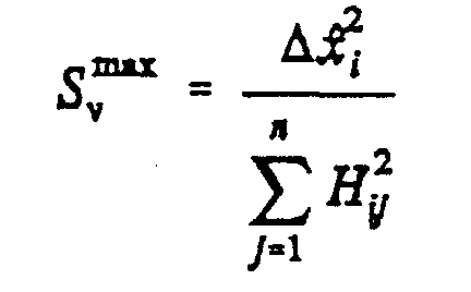
- the lower limits for the threshold values S min for a given, maximum permissible false alarm rate P f are through determined, and the upper limits for the threshold values S max can with a maximum permissible error ⁇ x i of the i-th component of the measured variable to be determined can be estimated, where H ij are the elements of the "least squares" transformation matrix. 2 shows the relationship between the selected threshold value (in units of ⁇ 2 of the sensor inaccuracy) and the resulting false alarm probability.
- the threshold values determined in this way cause the desired false alarm rate and error limits for the measured variable under nominal conditions, that is to say if the sensor inaccuracy of the error-free sensors has the assumed distribution. However, under certain circumstances, in which (temporarily) all sensors show greater inaccuracies than assumed, undesired error detections can occur. To avoid this, the threshold values can be dynamically adapted to the lowest inconsistency of the highest error level, that is to say to the inconsistency of the best sensor combination with a minimum number of redundant sensors.
- the norm of the parity vector is determined and the parity vector is standardized in a suitable manner (block 2).
- a standardization that is particularly suitable for the purpose required here is to normalize the maximum component in magnitude by multiplying all components by a factor of +1.
- the index of the maximum component serves as the first component of the table key.
- the remaining part of the table key is then obtained from the remaining components of the parity vector by quantizing the respective value range [-1, + 1] into q sections of equal size.
- the isolation information stored under this key (block 4) is called up.
- the f best sensor combinations are kept ready for each error level f in the order of increasing inconsistency.
- the sensor combination that is actually to be used is then selected. For each sensor combination there is a separate least-squares transformation matrix H i , in which the sensors to be omitted are no longer taken into account, and the value of the quantity to be measured results from the measurement vector according to (2).
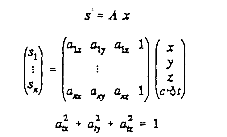
- the measurement equation here according to the usual linearization by a known approximate value for the position, has the form for n observed satellites where the components s i of the measurement vector characterize the measured pseudo distances to the individual satellites, x, y, z and ⁇ t the components of the position correction or the error of the receiver clock.
- the first 3 elements of each line in the measurement matrix are the direction cosines of the connecting line between the satellite and the approximate position.
Description
- Messung von Bewegung in Inertialsystemen mit redundanten (eventuell schiefachsigen) Inertialsensoren (Kreisel, Beschleunigungsmesser),
- Positionsbestimmung in Satellitennavigationssystemen bei redundanter Satellitenkonfiguration
- die Gruppierung der Gesamtsensoren in Sensorkombinationen mit minimaler Redundanz mit Bewertung aller Einzelkombinationen und anschliessender kombinatorischer Logik zur Bestimmung der größtmöglichen fehlerfreien Sensorkombination (Paritätsverfahren).
- die Isolierung desjenigen einzelnen Sensors, der am meisten zur Gesamtdiskrepanz beiträgt (Chi-Square Kriterium) und anschließendem Weglassen dieses Sensors ("Maximum-Likelihood"-Verfahren).
bei Paritätsverfahren:
- die Zahl der zu betrachtenden Einzelkombinationen mit minimaler Redundanz wächst kombinatorisch (d.h. wie n!) mit der Zahl der Sensoren. Da die Parität jeder Kombination bewertet werden muß, steigt der Aufwand des Verfahrens in gleichem Maße.
- die Bewertung jeder Einzelparität erfolgt diskret als entweder "Gut" oder "Schlecht" durch Vergleich mit vorgegebenen Schwellwerten. Eine Parität, die einen Schwellwert nur knapp verletzt, wird nicht unterschieden von einer großen Schwellwertverletzung. Gleiches gilt für Schwellwertunterschreitungen. Das resultierende Gesamtmuster der Paritätsverletzungen erlaubt dadurch in einem verhältnismäßig breiten Bereich von Sensorfehlern keine eindeutige Interpretation und muß mit Hilfe von Heuristiken interpretiert werden. Dies kann zu unnötigen Fehlinterpretationen führen. Die zusätzliche Einführung verschiedener ("großer" und "kleiner") Schwellwerte kann dieses Problem nur teilweise abmildern und erhöht den Aufwand des Verfahrens.
- bedingt durch die in der Regel feste Wahl von Schwellwerten führt ein unerwartet großes Rauschen aller Sensorwerte zu einem vollständigen Versagen des Verfahrens, da möglicherweise alle Einzelkombinationen die Schwellwerte überschreiten und jenseits der Schwellwerte nicht mehr differenziert wird. Zur Vermeidung dieses Problems müssen die Schwellwerte an den schlimmstmöglichen Fall angepaßt werden, was zu unerwünscht großer Unempfindlichkeit des Verfahrens im "Normalbetrieb" führt.
- bedingt durch die grobe Einteilung der Einzelparitäten in größer/kleiner als Schwellwert, können Singularitäten, das heißt Sensordatenkombinationen, die eine eindeutige Isolation des Fehlers prinzipiell nicht zulassen, nur grob erfaßt und nur teilweise von eindeutigen Situationen unterschieden werden. Dies hat zur Folge, daß entweder Singularitäten unentdeckt bleiben, oder daß auch eigentlich eindeutige Fälle als Singularität behandelt werden. Die Nichtentdeckung von Singularitäten kann zu Fehlentscheidungen führen und auch die Behandlung von eigentlich eindeutigen Fällen als Singularität kann die Integrität des Verfahrens mindern, da bei der Singularitätsbehandlung in der Regel auf weniger verläßliche Information zurückgegriffen wird.
- Da diese Verfahren davon ausgehen, daß zu einer bestimmten Zeit jeweils nur ein Sensor fehlerhafte Daten liefert, können beim gleichzeitigen tatsächlichen Auftreten von Mehrfachfehlern falsche Isolationsentscheidungen getroffen werden.
- Nach dem Auftreten und der Isolation eines Einzelfehlers müssen die Parameter des Verfahrens in Echtzeit auf die entsprechende (n-1)-Sensor Konfiguration umkonfiguriert werden, um auch eventuell später auftretende weitere Einzelfehler zu erkennen und zu isolieren. Das weitere Verhalten der bisher als fehlerhaft isolierten Sensoren geht in dieser neuen Konfiguration nicht mehr ein. Eine eventuell erfolgende "Heilung" dieser Sensoren kann nur durch parallele Bearbeitung mehrerer Konfigurationen erkannt werden, was den Verarbeitungsaufwand des Verfahrens entsprechend erhöht.
- die geometrische Interpretation der Eigenschaften des Paritätsraums und deren konsequente Nutzung zur Isolation von gleichzeitig auftretenden Mehrfachfehlern;
- die "Off-Line"-Analyse der Richtungen im Paritätsraum und das Bereitstellen der Isolationsergebnisse in einer vorab berechneten Tabelle, sowie durch
- die wahlweise mögliche adaptive Anpassung der Detektionsschwellen an das allgemeine Rauschen der fehlerfreien Sensoren.
- 8 eindimensionale Unterräume (Geraden) zur Charakterisierung von Ein-Achsen Fehlern
- 28 zweidimensionale Unterräume (Ebenen) zur Charakterisierung von Zwei-Achsen Fehlern
- 56 dreidimensionale Unterräume zur Charakterisierung von Drei-Achsen Fehlern
- 70 vierdimensionale Unterräume zur Charakterisierung von Vier-Achsen Fehlern
- die Fehlerisolation erfolgt schwellwertfrei, das heißt, sie kann ohne "a priori" Annahmen über tatsächliches Rauschen der fehlerfreien Sensoren erfolgen.
- die tatsächlich erreichbare Empfindlichkeit der Fehlererkennung, und damit die Güte des Ausgangssignals, kann adaptiv an das Rauschen der fehlerfreien Sensoren angepaßt werden.
- bei der Isolation des Fehlers werden scheinbare Singularitäten vermieden und tatsächliche Singularitäten werden als solche erkannt.
- im Gegensatz zu existierenden Paritätsverfahren wird der in Echtzeit zu leistende Verarbeitungsaufwand zur Fehlererkennung und Isolation im Prinzip allein durch die Dimension des Paritätsraumes bestimmt und ist unabhängig von der Zahl der möglichen Sensorkombinationen. So können beispielsweise die 163 möglichen Kombinationen von 8 einachsigen, schiefachsig angeordneten Beschleunigungsmessern mit dem gleichen Aufwand isoliert werden wie die 11 möglichen Kombinationen von 4 zweiachsigen, schiefachsig angeordneten Kreiseln.
- im Gegensatz zu existierenden "Maximum Likelihood"-Verfahren werden auch gleichzeitig auftretende Mehrfachfehler im Rahmen der prinzipiellen Grenzen immer richtig erkannt und isoliert.
- im Abschnitt A die Grundlagen,
- im Abschnitt B die Durchführung des Verfahrens zur Fehlererkennung anhand von Flußdiagrammen und
- im Abschnitt C zwei Anwendungsbeispiele
- Fig. 1
- eine statistische Dichteverteilung (Chi-Quadratverteilung) der resultierenden Länge eines Paritätsvektors für Freiheitsgrade von 1 bis 5 veranschaulicht;
- Fig. 2
- Falschalarmwahrscheinlichkeiten in Abhängigkeit von vorgebbaren Schwellenwerten für verschiedene Freiheitsgrade erkennen läßt;
- Fig. 3
- das Flußdiagramm eines erfindungsgemäßen Verfahrensablaufs verdeutlicht;
- Fig. 4
- einen Verfahrensablauf mit gespeicherter Isolationsentscheidung zeigt; und
- Fig. 5
- den Paritätsraum für ein Anwendungsbeispiel verdeutlicht, bei dem zur Messung einer skalaren Meßgröße vier Sensoren vorgesehen sind.


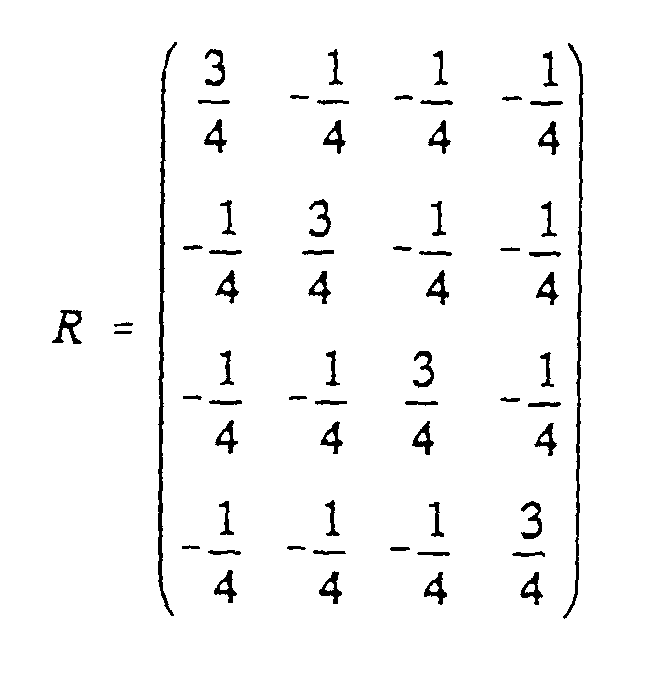
| Projektionsmatrizen für die charakteristischen Unterräume des 4-Thermometerbeispiels. | ||
| Zahl der fehlerhaften Sensoren | Fehlerhafte(r) Sensor(en) | Projektionsmatrizen |
| 1 | 1 | |
| 1 | 2 | |
| 1 | 3 | |
| 1 | 4 | |
| 2 | 1,2 | |
| 2 | 1,3 | |
| 2 | 1,4 | |
| 2 | 2,3 | |
| 2 | 2,4 | |
| 2 | 3,4 | |
Claims (5)
- Verfahren zur Minimierung von aus mit möglichen Meßfehlern behafteten Sensoren abgeleiteten Meßgrößen, die über eine Mehrzahl solcher zu einer Meßanordnung verbundener redundanter Sensoren erfaßt werden, durch Erkennen und Isolation eines fehlerhaften Sensors, wobei:a) die von allen Sensoren gemessenen, zu einem Meßvektor kombinierten Sensorwerte durch eine lineare Transformation in einen Vektor in einem Paritätsraum (Paritätsvektor) abgebildet werden, dessen Dimension durch die Redundanz der Meßanordnung, d.h. durch die Anzahl und/oder Orientierung der Sensoren und die Dimension der zu messenden Größe bestimmt ist; undb) die absolute Größe des Paritätsvektors bestimmt und gegenüber einer ersten Detektionsschwelle verglichen wird, und falls diese erste Detektionsschwelle nicht überschritten wird, auf fehlerfreien Zustand geschlossen wird,c) bei Überschreiten der Detektionsschwelle zum Erkennen und Isolieren von mehreren gleichzeitig auftretenden fehlerhaften Sensoren der gemessene Paritätsvektor auf alle für die möglichen Fehlerzustände charakteristischen Unterräume projiziert wird, deren Dimensionen bestimmt sind durch die zu dem jeweiligen Fehlerzustand gehörende Anzahl möglicher fehlerhafter Sensoren, und zur Fehlerisolation festgestellt wird, welche Projektion des Paritätsvektors auf einen, jeweils zu der betreffenden Fehlerbestimmungsstufe gehörenden Unterraum den größten Anteil des gemessenen Paritätsvektors liefert, dadurch gekennzeichnet, daß sodannd) geprüft wird, ob der verbleibende Restfehler eine zweite Detektionsschwelle überschreitet, und falls diese zweite Detektionsschwelle nicht überschritten wird, zum Verfahrensschritt e) übergegangen wird, während, wenn diese zweite Detektionsschwelle überschritten wird, mit der nächsten Fehlerbestimmungsstufe und dekrementierter zweiter Detektionsschwelle wiederum die Verfahrensschritte c) und analog d) durchgeführt werden, und daße) durch Weglassen der zu den jeweiligen Unterräumen mit größtem Anteil des Paritätsvektors gehörenden Sensorwertekombination auf der betreffenden Fehlerbestimmungsstufe die beste Sensorkombination ermittelt wird.
- Verfahren nach Anspruch 1, dadurch gekennzeichnet, daß die Fehlerisolation durch Berechnung aller möglichen Projektionen der Paritätsvektoren auf die charakteristischen Unterräume off-line oder durch eine Hintergrundverarbeitung durchführt und das Ergebnis in einer Tabelle gespeichert bereitgehalten wird, auf deren Elemente über die entsprechend codierte Richtung des Paritätsvektors als Tabellenschlüssel zurückgegriffen wird.
- Verfahren nach Anspruch 1 oder 2, dadurch gekennzeichnet, daß die Detektionsschwellen durch externe Vorgabe wählbar sind.
- Verfahren nach einem der vorhergehenden Ansprüche, dadurch gekennzeichnet, daß zumindest die erste Detektionsschwelle durch mögliche Rauschwerte und/oder zulässige Ungenauigkeiten der Sensoren bestimmt ist.
- Verfahren nach einem der vorhergehenden Ansprüche, dadurch gekennzeichnet, daß bei der Vorgabe der Detektionsschwellen die Anzahl der Sensoren berücksichtigt wird.
Applications Claiming Priority (2)
| Application Number | Priority Date | Filing Date | Title |
|---|---|---|---|
| DE4446900 | 1994-12-27 | ||
| DE4446900 | 1994-12-27 |
Publications (3)
| Publication Number | Publication Date |
|---|---|
| EP0720004A2 EP0720004A2 (de) | 1996-07-03 |
| EP0720004A3 EP0720004A3 (de) | 1996-08-07 |
| EP0720004B1 true EP0720004B1 (de) | 2000-02-16 |
Family
ID=6537322
Family Applications (1)
| Application Number | Title | Priority Date | Filing Date |
|---|---|---|---|
| EP95117943A Expired - Lifetime EP0720004B1 (de) | 1994-12-27 | 1995-11-14 | FDIC-Verfahren zur Minimierung von Messfehlern in einer Messanordnung von redundanten Sensoren |
Country Status (5)
| Country | Link |
|---|---|
| US (1) | US5661735A (de) |
| EP (1) | EP0720004B1 (de) |
| JP (1) | JP2635952B2 (de) |
| CA (1) | CA2165489A1 (de) |
| DE (1) | DE59507817D1 (de) |
Families Citing this family (31)
| Publication number | Priority date | Publication date | Assignee | Title |
|---|---|---|---|---|
| IT1286727B1 (it) * | 1996-10-10 | 1998-07-17 | Magneti Marelli Spa | Metodo per il trattamento di una pluralita' di segnali |
| US6009355A (en) * | 1997-01-28 | 1999-12-28 | American Calcar Inc. | Multimedia information and control system for automobiles |
| DE19704582A1 (de) * | 1997-02-07 | 1998-08-20 | Rollei Fototechnic Gmbh | Verfahren zur Ausgleichung von Meßwerten oder zur Vergleichmäßigung der Beanspruchung der über Knoten miteinander verbundenen Strecken eines Streckennetzes, sowie nach dem Verfahren dimensioniertes Streckennetz |
| EP0913746A3 (de) * | 1997-10-31 | 2000-04-12 | Honeywell Inc. | Einrichtung zur Fühler-Invalidierung |
| US6594620B1 (en) | 1998-08-17 | 2003-07-15 | Aspen Technology, Inc. | Sensor validation apparatus and method |
| WO2000010059A1 (en) * | 1998-08-17 | 2000-02-24 | Aspen Technology, Inc. | Sensor validation apparatus and method |
| US6876991B1 (en) | 1999-11-08 | 2005-04-05 | Collaborative Decision Platforms, Llc. | System, method and computer program product for a collaborative decision platform |
| US6917839B2 (en) * | 2000-06-09 | 2005-07-12 | Intellectual Assets Llc | Surveillance system and method having an operating mode partitioned fault classification model |
| US6609036B1 (en) * | 2000-06-09 | 2003-08-19 | Randall L. Bickford | Surveillance system and method having parameter estimation and operating mode partitioning |
| US6598195B1 (en) * | 2000-08-21 | 2003-07-22 | General Electric Company | Sensor fault detection, isolation and accommodation |
| AT4497U3 (de) * | 2001-03-28 | 2001-12-27 | Avl List Gmbh | Verfahren zur analyse und bewertung von messwerten eines offenen prüfsystems |
| US20040088341A1 (en) * | 2001-12-12 | 2004-05-06 | Lee Susan C | Method for converting a multi-dimensional vector to a two-dimensional vector |
| US7093168B2 (en) * | 2002-01-22 | 2006-08-15 | Honeywell International, Inc. | Signal validation and arbitration system and method |
| FR2842596B1 (fr) * | 2002-07-16 | 2005-06-10 | Commissariat Energie Atomique | Procede de test de bon fonctionnement de capteur de mesures |
| US7451003B2 (en) * | 2004-03-04 | 2008-11-11 | Falconeer Technologies Llc | Method and system of monitoring, sensor validation and predictive fault analysis |
| FR2871949B1 (fr) * | 2004-06-21 | 2006-09-01 | Renault Sas | Procede de surveillance d'un ou plusieurs parametres physiques et pile a combustible l'utilisant |
| CA2615161A1 (en) * | 2006-12-21 | 2008-06-21 | Aquatic Informatics Inc. | Automated validation using probabilistic parity space |
| US7805245B2 (en) * | 2007-04-18 | 2010-09-28 | Honeywell International Inc. | Inertial measurement unit fault detection isolation reconfiguration using parity logic |
| KR100964793B1 (ko) * | 2007-05-03 | 2010-06-21 | 중앙대학교 산학협력단 | 센서의 고장 검출 및 분리 방법 그리고 이를 이용한 센서의고장 적응 방법 |
| US7502705B2 (en) * | 2007-05-29 | 2009-03-10 | International Business Machines Corporation | Sensor subset selection for reduced bandwidth and computation requirements |
| DE102011075545A1 (de) | 2011-05-10 | 2012-11-15 | Robert Bosch Gmbh | Verfahren und Vorrichtung zur Überprüfung eines Sensorsignals und zur Ansteuerung eines Insassenschutzmittels eines Fahrzeugs |
| US9261614B2 (en) * | 2012-06-18 | 2016-02-16 | Halliburton Energy Services, Inc. | Statistics-based seismic event detection |
| FR3017705B1 (fr) * | 2014-02-18 | 2017-07-07 | Airbus Operations Sas | Procede de fusion de donnees de capteurs. |
| CN105424035B (zh) * | 2015-10-30 | 2018-06-01 | 北京航天控制仪器研究所 | 惯性测量系统多传感器冗余方法 |
| US20170284903A1 (en) * | 2016-03-30 | 2017-10-05 | Sas Institute Inc. | Monitoring machine health using multiple sensors |
| US10560313B2 (en) | 2018-06-26 | 2020-02-11 | Sas Institute Inc. | Pipeline system for time-series data forecasting |
| US10685283B2 (en) | 2018-06-26 | 2020-06-16 | Sas Institute Inc. | Demand classification based pipeline system for time-series data forecasting |
| US20210247753A1 (en) * | 2020-02-07 | 2021-08-12 | Kabushiki Kaisha Yaskawa Denki | State estimation device, system, and manufacturing method |
| CN113324505B (zh) * | 2021-04-23 | 2022-06-14 | 上海卫星工程研究所 | 一种双超卫星舱间位移传感器一致性判断方法及系统 |
| CN113189968B (zh) * | 2021-05-08 | 2022-08-26 | 哈尔滨工业大学 | 互联工业过程的分布式故障诊断方法 |
| CN115790670B (zh) * | 2023-02-10 | 2023-05-05 | 中国科学院国家空间科学中心 | 一种冗余捷联惯组故障检测方法及系统 |
Family Cites Families (9)
| Publication number | Priority date | Publication date | Assignee | Title |
|---|---|---|---|---|
| US4472806A (en) * | 1982-05-03 | 1984-09-18 | The Boeing Company | Signal selection and fault detection apparatus |
| US4580234A (en) * | 1982-08-02 | 1986-04-01 | Nippon Business Consultant Co., Ltd. | Measurement system of enhanced reliability |
| US4772445A (en) * | 1985-12-23 | 1988-09-20 | Electric Power Research Institute | System for determining DC drift and noise level using parity-space validation |
| FI896219A0 (fi) * | 1989-04-28 | 1989-12-22 | Antti Aarne Ilmari Lange | Anordning och foerfarande foer kalibrering av detektorsystem. |
| DE3929404A1 (de) * | 1989-09-05 | 1991-03-07 | Bodenseewerk Geraetetech | Verfahren und vorrichtung zum erkennen und identifizieren von fehlern an sensoren |
| DE4100501A1 (de) * | 1991-01-10 | 1992-07-16 | Bodenseewerk Geraetetech | Verfahren und einrichtung zum erkennen von fehlern an sensoren fuer zustandsgroessen |
| JPH05281199A (ja) * | 1992-03-31 | 1993-10-29 | Nuclear Fuel Ind Ltd | 探傷データ評価装置及び方法 |
| DE4244014A1 (de) * | 1992-12-24 | 1994-07-07 | Bodenseewerk Geraetetech | Verfahren zum Erkennen und Identifizieren von Fehlern an Sensoren |
| US5479161A (en) * | 1994-03-25 | 1995-12-26 | Honeywell Inc. | Automatic calibration of redundant sensors |
-
1995
- 1995-11-14 EP EP95117943A patent/EP0720004B1/de not_active Expired - Lifetime
- 1995-11-14 DE DE59507817T patent/DE59507817D1/de not_active Expired - Fee Related
- 1995-12-18 CA CA002165489A patent/CA2165489A1/en not_active Abandoned
- 1995-12-26 US US08/578,840 patent/US5661735A/en not_active Expired - Fee Related
- 1995-12-27 JP JP7341848A patent/JP2635952B2/ja not_active Expired - Lifetime
Also Published As
| Publication number | Publication date |
|---|---|
| DE59507817D1 (de) | 2000-03-23 |
| US5661735A (en) | 1997-08-26 |
| CA2165489A1 (en) | 1996-06-28 |
| EP0720004A3 (de) | 1996-08-07 |
| JPH08233620A (ja) | 1996-09-13 |
| EP0720004A2 (de) | 1996-07-03 |
| JP2635952B2 (ja) | 1997-07-30 |
Similar Documents
| Publication | Publication Date | Title |
|---|---|---|
| EP0720004B1 (de) | FDIC-Verfahren zur Minimierung von Messfehlern in einer Messanordnung von redundanten Sensoren | |
| DE69930501T2 (de) | Ultrasensitive überwachung von sensoren und prozessen | |
| DE4436658B4 (de) | Vorrichtung und Verfahren zur Störungsuntersuchung | |
| DE60309928T2 (de) | Verfahren zur erhöhung der sicherheitsintegritätsstufe eines kontrollsystems | |
| DE10297009T5 (de) | Sensorfusion unter Verwendung von selbstvaluierenden Prozesssensoren | |
| DE3928456A1 (de) | Verfahren und schaltungsanordnung zum bilden eines auswertungssignals aus einer mehrzahl redundanter messsignale | |
| EP2425308B1 (de) | Einrichtung und verfahren zur residuenauswertung eines residuums zur erkennung von systemfehlern im systemverhalten eines systems eines flugzeugs | |
| DE3639055C2 (de) | Verfahren zur Betriebsüberwachung und Fehlerkorrektur von Rechnern eines Mehrrechnersystems und Mehrrechnersystem | |
| DE10007972A1 (de) | Diagnosevorrichtung und -verfahren in einem Prozeßsteuersystem | |
| EP0494632A2 (de) | Signalverarbeitungsanordnung zur Klassifizierung von Objekten aufgrund der Signale von Sensoren | |
| DE10135586A1 (de) | Rekonfigurations-Verfahren für ein Sensorsystem mit zumindest einem Satz von Beobachtern zur Ausfallkompensation und Sicherstellung einer Meßwertgüte | |
| EP0416370B1 (de) | Verfahren und Vorrichtung zum Erkennen und Identifizieren von Fehlern an Sensoren | |
| DE4100501A1 (de) | Verfahren und einrichtung zum erkennen von fehlern an sensoren fuer zustandsgroessen | |
| EP3282399B1 (de) | Verfahren zur verbesserten erkennung von prozessanomalien einer technischen anlage sowie entsprechendes diagnosesystem | |
| DE19919504A1 (de) | Triebwerksregler, Triebwerk und Verfahren zum Regeln eines Triebwerks | |
| EP2122382B1 (de) | Verfahren zum erhöhen der verfügbarkeit eines globalen navigationssystems | |
| EP2857916A1 (de) | Verfahren und Vorrichtung zum Detektieren eines Fehlers in einer Anordnung | |
| EP1306736B1 (de) | Verfahren zur Überwachung von Bearbeitungsanlagen | |
| DE102019124301A1 (de) | Vorrichtung und Verfahren zur Gewährleistung der Fail-Safe-Funktion eines autonomen Fahrsystems | |
| EP0921374B1 (de) | Verfahren zur Erkennung von Abweichungen der Oberflächenform von einer vorgegebenen Form durch eine Verarbeitung mit einem künstlichen neuronalen Netz | |
| DE102020107950A1 (de) | Verfahren zur Fehleraufdeckung und sicheres Sensorsystem | |
| DE102008011165B4 (de) | Sensoranordnung für ein Insassenschutzsystem eines Kraftfahrzeugs | |
| EP3582050B1 (de) | Verfahren zum analysieren einer ursache mindestens einer abweichung | |
| DE102004025574B4 (de) | Verfahren zur Fehlererkennung in einem industriellen Prozess | |
| EP3728995A1 (de) | Verfahren zum bestimmen von entfernungsinformation aus einer abbildung eines raumbereichs |
Legal Events
| Date | Code | Title | Description |
|---|---|---|---|
| PUAI | Public reference made under article 153(3) epc to a published international application that has entered the european phase |
Free format text: ORIGINAL CODE: 0009012 |
|
| PUAL | Search report despatched |
Free format text: ORIGINAL CODE: 0009013 |
|
| AK | Designated contracting states |
Kind code of ref document: A2 Designated state(s): DE ES FR GB IT |
|
| AK | Designated contracting states |
Kind code of ref document: A3 Designated state(s): DE ES FR GB IT |
|
| 17P | Request for examination filed |
Effective date: 19961210 |
|
| 17Q | First examination report despatched |
Effective date: 19970408 |
|
| GRAG | Despatch of communication of intention to grant |
Free format text: ORIGINAL CODE: EPIDOS AGRA |
|
| GRAG | Despatch of communication of intention to grant |
Free format text: ORIGINAL CODE: EPIDOS AGRA |
|
| GRAH | Despatch of communication of intention to grant a patent |
Free format text: ORIGINAL CODE: EPIDOS IGRA |
|
| GRAH | Despatch of communication of intention to grant a patent |
Free format text: ORIGINAL CODE: EPIDOS IGRA |
|
| GRAA | (expected) grant |
Free format text: ORIGINAL CODE: 0009210 |
|
| AK | Designated contracting states |
Kind code of ref document: B1 Designated state(s): DE ES FR GB IT |
|
| PG25 | Lapsed in a contracting state [announced via postgrant information from national office to epo] |
Ref country code: IT Free format text: LAPSE BECAUSE OF FAILURE TO SUBMIT A TRANSLATION OF THE DESCRIPTION OR TO PAY THE FEE WITHIN THE PRE;WARNING: LAPSES OF ITALIAN PATENTS WITH EFFECTIVE DATE BEFORE 2007 MAY HAVE OCCURRED AT ANY TIME BEFORE 2007. THE CORRECT EFFECTIVE DATE MAY BE DIFFERENT FROM THE ONE RECORDED.SCRIBED TIME-LIMIT Effective date: 20000216 Ref country code: FR Free format text: LAPSE BECAUSE OF FAILURE TO SUBMIT A TRANSLATION OF THE DESCRIPTION OR TO PAY THE FEE WITHIN THE PRESCRIBED TIME-LIMIT Effective date: 20000216 Ref country code: ES Free format text: THE PATENT HAS BEEN ANNULLED BY A DECISION OF A NATIONAL AUTHORITY Effective date: 20000216 |
|
| REF | Corresponds to: |
Ref document number: 59507817 Country of ref document: DE Date of ref document: 20000323 |
|
| GBT | Gb: translation of ep patent filed (gb section 77(6)(a)/1977) |
Effective date: 20000522 |
|
| EN | Fr: translation not filed | ||
| PLBE | No opposition filed within time limit |
Free format text: ORIGINAL CODE: 0009261 |
|
| STAA | Information on the status of an ep patent application or granted ep patent |
Free format text: STATUS: NO OPPOSITION FILED WITHIN TIME LIMIT |
|
| 26N | No opposition filed | ||
| REG | Reference to a national code |
Ref country code: GB Ref legal event code: IF02 |
|
| PGFP | Annual fee paid to national office [announced via postgrant information from national office to epo] |
Ref country code: DE Payment date: 20071126 Year of fee payment: 13 |
|
| PGFP | Annual fee paid to national office [announced via postgrant information from national office to epo] |
Ref country code: GB Payment date: 20071123 Year of fee payment: 13 |
|
| GBPC | Gb: european patent ceased through non-payment of renewal fee |
Effective date: 20081114 |
|
| PG25 | Lapsed in a contracting state [announced via postgrant information from national office to epo] |
Ref country code: DE Free format text: LAPSE BECAUSE OF NON-PAYMENT OF DUE FEES Effective date: 20090603 |
|
| PG25 | Lapsed in a contracting state [announced via postgrant information from national office to epo] |
Ref country code: GB Free format text: LAPSE BECAUSE OF NON-PAYMENT OF DUE FEES Effective date: 20081114 |