EP0724230A2 - Image processing method and apparatus - Google Patents
Image processing method and apparatus Download PDFInfo
- Publication number
- EP0724230A2 EP0724230A2 EP96300500A EP96300500A EP0724230A2 EP 0724230 A2 EP0724230 A2 EP 0724230A2 EP 96300500 A EP96300500 A EP 96300500A EP 96300500 A EP96300500 A EP 96300500A EP 0724230 A2 EP0724230 A2 EP 0724230A2
- Authority
- EP
- European Patent Office
- Prior art keywords
- color
- image
- image data
- deciding
- stored
- Prior art date
- Legal status (The legal status is an assumption and is not a legal conclusion. Google has not performed a legal analysis and makes no representation as to the accuracy of the status listed.)
- Granted
Links
Images

Classifications
-
- G—PHYSICS
- G06—COMPUTING; CALCULATING OR COUNTING
- G06T—IMAGE DATA PROCESSING OR GENERATION, IN GENERAL
- G06T15/00—3D [Three Dimensional] image rendering
- G06T15/10—Geometric effects
- G06T15/40—Hidden part removal
Definitions
- the invention relates to an image processing method and apparatus for drawing by using position indicating means such as mouse, pen, or the like.
- the invention also relates to an image processing method and apparatus which can edit and output an input
- the above conventional technique has a drawback such that the editing operation to change the upper/lower relation when displaying an image after the image was once inputted has to be executed, so that an operability is bad.
- An object of another aspect of the invention is to solve the drawbacks of the conventional techniques mentioned above and to provide image processing method and apparatus in which a desired upper/lower relation can be set without needing an editing operation to change a mutual upper/lower relation of images when a plurality of images are displayed.
- An object of a further aspect of the invention is to provide image processing method and apparatus of a high operability in which by comparing a color set in an image to be drawn and a color of an image that has already been inputted to a position to draw the image and by overwriting an image in which a color of a high priority has been set, the picture of the image and the setting of the priority on the display of the image can be simultaneously performed.
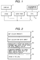
- Fig. 1 is a block diagram showing a construction of an image processing apparatus in an embodiment.
- Fig. 2 is a flowchart showing a drawing process.
- reference numeral 1 denotes a display for displaying an image as a result drawn, a menu which is necessary for various processes, a cursor of a coordinate designator 2, or the like.
- the display 1 is constructed by a CRT, a liquid crystal display (LCD), or the like.
- Reference numeral 2 denotes the coordinate designator such as mouse, pen, or the like to indicate a desired position on the display screen of the display 1.
- a VRAM 3 is a random access memory for storing data to be displayed.
- the VRAM 3 stores image data such as a figure or the like to be displayed on the display 1.
- a data RAM 4 is a random access memory to temporarily store data.
- the data RAM 4 stores various kinds of parameters such as information of the priorities of the set colors, data of the present drawing color, and the like which are used during the process.
- a CPU 5 executes and controls various kinds of processes, which will be explained in the embodiment, as shown in the flowchart of Fig. 2. The execution and control of the processes are executed on the basis of a control program stored in an ROM in the CPU 5.
- An address bus 6 is a bus for flowing address data to designate a position (address) to read or write data in the VRAM 3 and data RAM 4.
- a data bus 7 is a bus for flowing the data read out from the position designated by the address data flowing on the address bus 6.
- step S1 priorities of colors to be used for drawing are set.
- the process in step S1 is started by selecting an item "set priority of color" from the menu displayed on the display 1.
- the color to set the priority is selected from the sample colors by a method whereby a desired sample is designated by the pen or mouse is clicked or the like.
- a subwindow to input the priority to be set to the color is displayed on the display screen.
- a numerical value indicative of the priority to be set is inputted by using a keyboard (not shown) on the subwindow for setting the priority.
- the priority can be also inputted by indicating a soft numerical value key on the display screen by using the pen or mouse so that the color selecting operation can be continuously inputted.
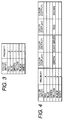
- Fig. 3 is a table showing the priorities of the colors set in step S1.
- the table is stored in the data RAM 4.
- the priorities 4, 3, 5, 2, 6, and 1 are set with regard to red, blue, green, yellow, black, and white selected from the colors which can be displayed on the display 1, namely, which can be set in an image to be drawn by the coordinate designator 2.
- the priority of white is the highest and the priority of black is the lowest. In this case, the image of white is displayed over the images of all of the other colors.
- step S1 When an item of "end” is designated by the operator and the priority setting process of the color (S1) is finished, the priorities of the colors set until this time point are stored into the data RAM 4 and a setting process of a drawing color (step S2) is started.
- the drawing color setting process is also started by designating an item of "set input color" by the operator by using the pen or mouse.
- the color set in step S2 and the priority data of such a color which has been stored in the data RAM 4 are stored into the data RAM 4.
- a picture which is inputted by the pen, mouse, or keyboard is displayed on the display screen by the designated color.
- the drawing of the picture is executed in steps S3 and S4.
- the detailed process of the drawing portion is shown in a flowchart of Fig. 5.
- step S3 when an arbitrary point on the display screen is designated by the coordinate designator 2 or the keyboard (S11), the address in the VRAM 3 to store the color data of the designated point is indicated by the CPU 5 through the address bus 6 (S12).
- the color data stored in the address is sent to the CPU 5 through the data bus 7 (S13).
- the CPU 5 reads out the priority of the color data sent and the priority of the color to be inputted from the data RAM 4 (S14) and compares the values of those two priorities (S15). As a result of the comparison, when the priority of the color to be inputted is higher than the priority of the color displayed, the CPU 5 writes the color data of the color to be inputted into the address corresponding to the point designated in the VRAM 3 (S16).
- the priority of the color displayed is higher than the priority of the color to be inputted, the data in the address corresponding to the point designated in the VRAM 3 is held without changing.
- the data in the VRAM 3 is displayed on the display 1 (S5).
- the overwriting process is executed with attention paid to only the priority of the color.
- the relation between the color and the priority in this instance is as shown in, for example, a table of Fig. 3.
- a table of Fig. 3 By expanding the table as shown in Fig. 4 and by changing output color information for the color information which was read out, not only a judgment about whether the drawn data is overwritten or not in step S4 of the flowchart of Fig. 2 is performed but also the color in case of overwriting can be changed.
- the display is determined in accordance with the priority in a manner similar to the case of using the table of Fig. 3. For example, when the color to be inputted is yellow and the read-out color is white, since the priority of white is higher, white is displayed as it is. When the read-out color is blue, since the priority of yellow is higher, the display color is changed from blue to yellow. Thus, in the case where the table is set as shown in Fig. 4, so long as the color to be inputted other than yellow is set, the display color is decided by the priority with the read-out color.
- the process such that the display color can be changed on the basis of the relation between the display color and the input color or the overwriting cannot be performed can be executed. It is possible to construct in a manner such that even if an image is overwritten, the picture to be preserved is not erased.
- the image formed by the drawing process described above the data that is similar to that stored in the VRAM 3 is outputted from the printer (not shown) and the image can be obtained as a desired original.
- a printer such as LBP, ink jet printer, or the like which can output a color image or a printer which can output a gray scale can be used.
- the invention is not limited to it.
- the invention can be also applied to the case where the image inputted through a scanner or a communication line is overwritten to the image which has already been inputted and the resultant image is inputted.
- VRAM data about each dot (S12) of such an image is read out (S13), the priority is read out (S14), and a judgment about the input color and the display color is performed (S15).
- As an input color so long as the input image is a color image, it is sufficient to read out the color of the dot and to store into the data RAM 4 in step S11.
- the image is inputted, so long as the color is designated for the whole image (S2) irrespective of the color set in the input image, it is sufficient to store the set color into the data RAM 4.
Abstract
Description
- The invention relates to an image processing method and apparatus for drawing by using position indicating means such as mouse, pen, or the like.
- The invention also relates to an image processing method and apparatus which can edit and output an input
- Hitherto, when a new image is inputted to an image which has already been inputted, the newly inputted image is overwritten onto the image which has already been inputted.
- Hitherto, there is an editing function such that the upper/lower relation when displaying an image which has already been inputted can be changed.
- According to the above conventional technique, however, since a display color is unconditionally changed with respect to the overwritten portion, there is a problem such that in the case where an image is erroneously drawn onto a figure to be preserved, the figure to be preserved is erased.
- The above conventional technique has a drawback such that the editing operation to change the upper/lower relation when displaying an image after the image was once inputted has to be executed, so that an operability is bad.
- It is an object of one aspect of the invention to solve the problems of the conventional techniques mentioned above and to provide image processing method and apparatus in which even when an image is overwritten, a figure to be preserved is not erased.
- An object of another aspect of the invention is to solve the drawbacks of the conventional techniques mentioned above and to provide image processing method and apparatus in which a desired upper/lower relation can be set without needing an editing operation to change a mutual upper/lower relation of images when a plurality of images are displayed.
- An object of a further aspect of the invention is to provide image processing method and apparatus of a high operability in which by comparing a color set in an image to be drawn and a color of an image that has already been inputted to a position to draw the image and by overwriting an image in which a color of a high priority has been set, the picture of the image and the setting of the priority on the display of the image can be simultaneously performed.
- Embodiments of the present invention will now be described with reference to the accompanying drawings in which:
- Fig. 1 is a block diagram showing a constructional example of an image processing apparatus according to one embodiment of the invention;
- Fig. 2 is a flowchart for a drawing process;
- Fig. 3 is a diagram showing an example of the setting of priorities of colors;
- Fig. 4 is a diagram showing an example of a display color change table; and
- Fig. 5 is a flowchart for a detailed drawing process.
- Fig. 1 is a block diagram showing a construction of an image processing apparatus in an embodiment. Fig. 2 is a flowchart showing a drawing process.
- In Fig. 1,
reference numeral 1 denotes a display for displaying an image as a result drawn, a menu which is necessary for various processes, a cursor of acoordinate designator 2, or the like. Thedisplay 1 is constructed by a CRT, a liquid crystal display (LCD), or the like.Reference numeral 2 denotes the coordinate designator such as mouse, pen, or the like to indicate a desired position on the display screen of thedisplay 1. AVRAM 3 is a random access memory for storing data to be displayed. The VRAM 3 stores image data such as a figure or the like to be displayed on thedisplay 1. Adata RAM 4 is a random access memory to temporarily store data. Thedata RAM 4 stores various kinds of parameters such as information of the priorities of the set colors, data of the present drawing color, and the like which are used during the process. ACPU 5 executes and controls various kinds of processes, which will be explained in the embodiment, as shown in the flowchart of Fig. 2. The execution and control of the processes are executed on the basis of a control program stored in an ROM in theCPU 5. Anaddress bus 6 is a bus for flowing address data to designate a position (address) to read or write data in theVRAM 3 anddata RAM 4. Adata bus 7 is a bus for flowing the data read out from the position designated by the address data flowing on theaddress bus 6. - A drawing process in the embodiment will now be described in accordance with the flowchart of Fig. 2. In step S1, priorities of colors to be used for drawing are set. The process in step S1 is started by selecting an item "set priority of color" from the menu displayed on the
display 1. In the setting process of the priority of the color, since samples of colors which can be displayed, namely, which can be set as drawing colors are displayed on the display screen, the color to set the priority is selected from the sample colors by a method whereby a desired sample is designated by the pen or mouse is clicked or the like. In response to the selecting operation, a subwindow to input the priority to be set to the color is displayed on the display screen. A numerical value indicative of the priority to be set is inputted by using a keyboard (not shown) on the subwindow for setting the priority. In case of inputting the priority, the priority can be also inputted by indicating a soft numerical value key on the display screen by using the pen or mouse so that the color selecting operation can be continuously inputted. - In step S1, the setting or changing operation of the priority of a new color is repeated with respect to each color until the operator instructs the end of setting. Fig. 3 is a table showing the priorities of the colors set in step S1. The table is stored in the
data RAM 4. In Fig. 3, thepriorities display 1, namely, which can be set in an image to be drawn by thecoordinate designator 2. The smaller the numerical value is, the higher the priority becomes. In the example of Fig. 3, the priority of white is the highest and the priority of black is the lowest. In this case, the image of white is displayed over the images of all of the other colors. - When an item of "end" is designated by the operator and the priority setting process of the color (S1) is finished, the priorities of the colors set until this time point are stored into the
data RAM 4 and a setting process of a drawing color (step S2) is started. - The drawing color setting process is also started by designating an item of "set input color" by the operator by using the pen or mouse. The color set in step S2 and the priority data of such a color which has been stored in the
data RAM 4 are stored into thedata RAM 4. After the color was set in step S2, a picture which is inputted by the pen, mouse, or keyboard is displayed on the display screen by the designated color. The drawing of the picture is executed in steps S3 and S4. The detailed process of the drawing portion is shown in a flowchart of Fig. 5. - In step S3, when an arbitrary point on the display screen is designated by the
coordinate designator 2 or the keyboard (S11), the address in theVRAM 3 to store the color data of the designated point is indicated by theCPU 5 through the address bus 6 (S12). The color data stored in the address is sent to theCPU 5 through the data bus 7 (S13). TheCPU 5 reads out the priority of the color data sent and the priority of the color to be inputted from the data RAM 4 (S14) and compares the values of those two priorities (S15). As a result of the comparison, when the priority of the color to be inputted is higher than the priority of the color displayed, theCPU 5 writes the color data of the color to be inputted into the address corresponding to the point designated in the VRAM 3 (S16). On the contrary, when the priority of the color displayed is higher than the priority of the color to be inputted, the data in the address corresponding to the point designated in theVRAM 3 is held without changing. The data in theVRAM 3 is displayed on the display 1 (S5). - By the above procedure, a process such that the overwriting is enabled or disabled by allocating the priority to the color can be performed. Even if an image is overwritten, a picture to be preserved is not erased.
- In the above description, the overwriting process is executed with attention paid to only the priority of the color. The relation between the color and the priority in this instance is as shown in, for example, a table of Fig. 3. By expanding the table as shown in Fig. 4 and by changing output color information for the color information which was read out, not only a judgment about whether the drawn data is overwritten or not in step S4 of the flowchart of Fig. 2 is performed but also the color in case of overwriting can be changed.
- Explanation will now be made with respect to Fig. 4 as an example. When the color which is inputted and is set in step S2 at present is yellow and the color which was read out and displayed in step S13 is green, olive-green is outputted from Fig. 4 and the display color is changed from green to olive-green. Similarly, when the color to be inputted is yellow and the color which was read out is red, the color to be outputted is brown.
- On the other hand, when the color in which the color change is not set in the table such as red, blue, or the like in Fig. 4 is inputted, the display is determined in accordance with the priority in a manner similar to the case of using the table of Fig. 3. For example, when the color to be inputted is yellow and the read-out color is white, since the priority of white is higher, white is displayed as it is. When the read-out color is blue, since the priority of yellow is higher, the display color is changed from blue to yellow. Thus, in the case where the table is set as shown in Fig. 4, so long as the color to be inputted other than yellow is set, the display color is decided by the priority with the read-out color.
- According to the embodiment as described above, by expanding the table describing the relation between the color and the priority, when overwriting, the process such that the display color can be changed on the basis of the relation between the display color and the input color or the overwriting cannot be performed can be executed. It is possible to construct in a manner such that even if an image is overwritten, the picture to be preserved is not erased. As for the image formed by the drawing process described above, the data that is similar to that stored in the
VRAM 3 is outputted from the printer (not shown) and the image can be obtained as a desired original. As a printer, a printer such as LBP, ink jet printer, or the like which can output a color image or a printer which can output a gray scale can be used. - Although the embodiment has been described with respect to the example in which the picture is inputted by the pen, mouse, keyboard, or the like, the invention is not limited to it. For example, the invention can be also applied to the case where the image inputted through a scanner or a communication line is overwritten to the image which has already been inputted and the resultant image is inputted. In this case, with respect to the newly inputted image (S11), VRAM data about each dot (S12) of such an image is read out (S13), the priority is read out (S14), and a judgment about the input color and the display color is performed (S15). As an input color, so long as the input image is a color image, it is sufficient to read out the color of the dot and to store into the
data RAM 4 in step S11. When the image is inputted, so long as the color is designated for the whole image (S2) irrespective of the color set in the input image, it is sufficient to store the set color into thedata RAM 4. - It will be understood that the input image may be a character pattern image which is generated from a character generator. In this case as well, when the character pattern of designated color and size and font style is generated from the character generator and written into the
VRAM 3, it is sufficient to read out the data from the VRAM 3 (S13) with respect to each dot (S12) to develop the character pattern and to execute the processes in steps S14 to S16.
Claims (18)
- An image processing apparatus characterized by comprising:
input means for inputting an image and color information of said image;
memory means for storing a color image;
indicating means for indicating a desired position of said image stored;
reading means for reading out a color of the image stored in said memory means at said indicated position;
color deciding means for deciding a color to be outputted in accordance with the color read out by said reading means and the color information inputted by said input means; and
control means for controlling said memory means so as to store the color decided by said color deciding means at said indicated position. - An apparatus according to claim 1, characterized in that said color deciding means decides the color to be outputted on the basis of a table in which a correlation of a plurality of colors has been stored.
- An apparatus according to claim 1, characterized in that said input means is a pen.
- An apparatus according to claim 1, characterized in that said input means is a mouse.
- An apparatus according to claim 1, characterized in that said input means is a keyboard.
- An apparatus according to claim 1, characterized in that said indicating means is a pen.
- An apparatus according to claim 1, characterized in that said indicating means is a mouse.
- An apparatus according to claim 1, characterized in that said indicating means is a keyboard.
- An apparatus according to claim 1, characterized in that said image is a character pattern.
- An apparatus according to claim 1, characterized by further having a printer to output the image stored in said memory means.
- An apparatus according to claim 1, characterized by further having an ink jet printer to output the image stored in said memory means.
- An image processing method characterized by comprising the steps of:
inputting an image and color information of said image;
indicating a desired position of an image stored in memory means;
reading out a color of the image stored in said memory means at said indicated position;
deciding a color to be outputted in accordance with said read-out color and said inputted color information; and
controlling said memory means so as to store said decided color at said indicated position. - A method according to claim 12, characterized in that said decision of the color is performed on the basis of a table in which a correlation of a plurality of colors has been stored.
- A method according to claim 12, characterized in that the image stored in said storing means is a character pattern.
- A method according to claim 12, characterized in that the image stored in said memory means is outputted by a printer.
- A method according to claim 12, characterized in that the image stored in said memory means is outputted by an ink jet printer.
- Image processing apparatus comprising means to receive color image data, memory means to store the color image data, assignment means for assigning a priority order to colors in the color image data, and display means for displaying the color image data, characterised by deciding means for deciding the color of image data to be displayed when further color image data is received which is to be displayed overlapping the displayed color image data by comparing the priorities of the colors in the overlap, said display means being adapted to display the color image data and further color image data with the color of the overlap as determined by the deciding means.
- A method of processing color image data comprising the steps of receiving first color image data, storing the first color image data, assigning a priority order to colors in the first color image data and displaying the first color image data characterised by the steps of receiving second color image data, deciding the color of the image data which is to be displayed overlapping the displayed color image data by comparing the priorities of the colors in the overlap, and displaying the first and second color image data with the color of the over lap as determined in the deciding step.
Applications Claiming Priority (3)
| Application Number | Priority Date | Filing Date | Title |
|---|---|---|---|
| JP7008987A JPH08202890A (en) | 1995-01-24 | 1995-01-24 | Plotting device |
| JP898795 | 1995-01-24 | ||
| JP8987/95 | 1995-01-24 |
Publications (3)
| Publication Number | Publication Date |
|---|---|
| EP0724230A2 true EP0724230A2 (en) | 1996-07-31 |
| EP0724230A3 EP0724230A3 (en) | 1997-07-09 |
| EP0724230B1 EP0724230B1 (en) | 2002-11-06 |
Family
ID=11708050
Family Applications (1)
| Application Number | Title | Priority Date | Filing Date |
|---|---|---|---|
| EP96300500A Expired - Lifetime EP0724230B1 (en) | 1995-01-24 | 1996-01-24 | Image processing method and apparatus |
Country Status (4)
| Country | Link |
|---|---|
| US (1) | US5805169A (en) |
| EP (1) | EP0724230B1 (en) |
| JP (1) | JPH08202890A (en) |
| DE (1) | DE69624600T2 (en) |
Families Citing this family (9)
| Publication number | Priority date | Publication date | Assignee | Title |
|---|---|---|---|---|
| US6128001A (en) * | 1997-04-04 | 2000-10-03 | Avid Technology, Inc. | Methods and apparatus for changing a color of an image |
| US6351557B1 (en) | 1998-04-03 | 2002-02-26 | Avid Technology, Inc. | Method and apparatus for color manipulation |
| US6847373B1 (en) | 1999-04-16 | 2005-01-25 | Avid Technology, Inc. | Natural color matching in a video editing system |
| US6552731B1 (en) | 1999-04-16 | 2003-04-22 | Avid Technology, Inc. | Multi-tone representation of a digital image on a digital nonlinear editing system |
| US6571255B1 (en) * | 1999-04-16 | 2003-05-27 | Robert Gonsalves | Modification of media with common attributes on a digital nonlinear editing system |
| US6417891B1 (en) | 1999-04-16 | 2002-07-09 | Avid Technology, Inc. | Color modification on a digital nonlinear editing system |
| US6477271B1 (en) | 2000-04-07 | 2002-11-05 | Avid Technology, Inc. | Secondary color modification of a digital image |
| US6928187B2 (en) * | 2000-04-07 | 2005-08-09 | Avid Technology, Inc. | Secondary color modification of a digital image |
| JP4032763B2 (en) * | 2002-02-08 | 2008-01-16 | 大成建設株式会社 | Method and system for restoring protected object by image |
Citations (3)
| Publication number | Priority date | Publication date | Assignee | Title |
|---|---|---|---|---|
| US4484187A (en) * | 1982-06-25 | 1984-11-20 | At&T Bell Laboratories | Video overlay system having interactive color addressing |
| WO1988001778A1 (en) * | 1986-08-25 | 1988-03-10 | Rohde & Schwarz, Inc. | Apparatus and method for monochrome/multicolor display and superimposed images |
| EP0568361A2 (en) * | 1992-04-29 | 1993-11-03 | Canon Kabushiki Kaisha | A colour generation and mixing device |
Family Cites Families (2)
| Publication number | Priority date | Publication date | Assignee | Title |
|---|---|---|---|---|
| JPH01115634A (en) * | 1987-10-30 | 1989-05-08 | Canon Inc | Color image forming device |
| US5581670A (en) * | 1993-07-21 | 1996-12-03 | Xerox Corporation | User interface having movable sheet with click-through tools |
-
1995
- 1995-01-24 JP JP7008987A patent/JPH08202890A/en not_active Withdrawn
-
1996
- 1996-01-23 US US08/590,436 patent/US5805169A/en not_active Expired - Lifetime
- 1996-01-24 DE DE69624600T patent/DE69624600T2/en not_active Expired - Lifetime
- 1996-01-24 EP EP96300500A patent/EP0724230B1/en not_active Expired - Lifetime
Patent Citations (4)
| Publication number | Priority date | Publication date | Assignee | Title |
|---|---|---|---|---|
| US4484187A (en) * | 1982-06-25 | 1984-11-20 | At&T Bell Laboratories | Video overlay system having interactive color addressing |
| WO1988001778A1 (en) * | 1986-08-25 | 1988-03-10 | Rohde & Schwarz, Inc. | Apparatus and method for monochrome/multicolor display and superimposed images |
| US4868552A (en) * | 1986-08-25 | 1989-09-19 | Rohde & Schwartz-Polarad | Apparatus and method for monochrome/multicolor display of superimposed images |
| EP0568361A2 (en) * | 1992-04-29 | 1993-11-03 | Canon Kabushiki Kaisha | A colour generation and mixing device |
Non-Patent Citations (1)
| Title |
|---|
| PATENT ABSTRACTS OF JAPAN vol. 013, no. 340 (M-857), 31 July 1989 & JP 01 115634 A (CANON INC), 8 May 1989, * |
Also Published As
| Publication number | Publication date |
|---|---|
| DE69624600T2 (en) | 2003-07-03 |
| EP0724230B1 (en) | 2002-11-06 |
| EP0724230A3 (en) | 1997-07-09 |
| US5805169A (en) | 1998-09-08 |
| DE69624600D1 (en) | 2002-12-12 |
| JPH08202890A (en) | 1996-08-09 |
Similar Documents
| Publication | Publication Date | Title |
|---|---|---|
| US5237653A (en) | Multiwindow control method and apparatus for work station having multiwindow function | |
| US6202073B1 (en) | Document editing system and method | |
| US5179655A (en) | Multiwindow control method and apparatus for work station having multiwindow function | |
| US7590308B2 (en) | Image processing apparatus, an image processing method, and a computer readable medium having recorded thereon a processing program for permitting a computer to perform image processing routines | |
| EP0212563B1 (en) | Display control method for multi-window system | |
| EP0740270B1 (en) | Image output device | |
| US5262760A (en) | Modifying a graphics display image | |
| EP0738951A1 (en) | Data processing method and apparatus to input and output trace data | |
| IE54823B1 (en) | Graphics display method and apparatus | |
| US5289568A (en) | Apparatus and method for drawing figures | |
| EP0724230A2 (en) | Image processing method and apparatus | |
| US4700182A (en) | Method for storing graphic information in memory | |
| US6567552B2 (en) | Image processing method and apparatus | |
| US5442736A (en) | Correlation of cursor position to shapes displayed on a video display screen | |
| JP3189182B2 (en) | Information processing device | |
| US5299301A (en) | Image displaying method and apparatus | |
| US5890179A (en) | Figure editing apparatus and method for displaying edited objects in a form different from objects not yet edited | |
| US5621865A (en) | Graphics processing apparatus using grid and a method thereof | |
| US5897647A (en) | Information processing apparatus and method and computer usable medium for storing an input character train in correspondence to a figure object to which the character train is instructed to be pasted | |
| JP3176080B2 (en) | Document processing method and apparatus | |
| JPH08202856A (en) | Picture processing method | |
| JP3138430B2 (en) | User interface screen creation support device | |
| JP2965811B2 (en) | Information processing apparatus and display method | |
| JP3136852B2 (en) | Touch panel screen creation method and device | |
| JP2858581B2 (en) | Image processing method and apparatus |
Legal Events
| Date | Code | Title | Description |
|---|---|---|---|
| PUAI | Public reference made under article 153(3) epc to a published international application that has entered the european phase |
Free format text: ORIGINAL CODE: 0009012 |
|
| AK | Designated contracting states |
Kind code of ref document: A2 Designated state(s): DE FR GB IT NL |
|
| PUAL | Search report despatched |
Free format text: ORIGINAL CODE: 0009013 |
|
| AK | Designated contracting states |
Kind code of ref document: A3 Designated state(s): DE FR GB IT NL |
|
| 17P | Request for examination filed |
Effective date: 19971119 |
|
| 17Q | First examination report despatched |
Effective date: 19991222 |
|
| GRAG | Despatch of communication of intention to grant |
Free format text: ORIGINAL CODE: EPIDOS AGRA |
|
| GRAG | Despatch of communication of intention to grant |
Free format text: ORIGINAL CODE: EPIDOS AGRA |
|
| GRAH | Despatch of communication of intention to grant a patent |
Free format text: ORIGINAL CODE: EPIDOS IGRA |
|
| GRAH | Despatch of communication of intention to grant a patent |
Free format text: ORIGINAL CODE: EPIDOS IGRA |
|
| GRAA | (expected) grant |
Free format text: ORIGINAL CODE: 0009210 |
|
| AK | Designated contracting states |
Kind code of ref document: B1 Designated state(s): DE FR GB IT NL |
|
| PG25 | Lapsed in a contracting state [announced via postgrant information from national office to epo] |
Ref country code: NL Free format text: LAPSE BECAUSE OF FAILURE TO SUBMIT A TRANSLATION OF THE DESCRIPTION OR TO PAY THE FEE WITHIN THE PRESCRIBED TIME-LIMIT Effective date: 20021106 Ref country code: IT Free format text: LAPSE BECAUSE OF FAILURE TO SUBMIT A TRANSLATION OF THE DESCRIPTION OR TO PAY THE FEE WITHIN THE PRESCRIBED TIME-LIMIT;WARNING: LAPSES OF ITALIAN PATENTS WITH EFFECTIVE DATE BEFORE 2007 MAY HAVE OCCURRED AT ANY TIME BEFORE 2007. THE CORRECT EFFECTIVE DATE MAY BE DIFFERENT FROM THE ONE RECORDED. Effective date: 20021106 |
|
| REG | Reference to a national code |
Ref country code: GB Ref legal event code: FG4D |
|
| REF | Corresponds to: |
Ref document number: 69624600 Country of ref document: DE Date of ref document: 20021212 |
|
| ET | Fr: translation filed | ||
| NLV1 | Nl: lapsed or annulled due to failure to fulfill the requirements of art. 29p and 29m of the patents act | ||
| PLBE | No opposition filed within time limit |
Free format text: ORIGINAL CODE: 0009261 |
|
| STAA | Information on the status of an ep patent application or granted ep patent |
Free format text: STATUS: NO OPPOSITION FILED WITHIN TIME LIMIT |
|
| 26N | No opposition filed |
Effective date: 20030807 |
|
| PGFP | Annual fee paid to national office [announced via postgrant information from national office to epo] |
Ref country code: FR Payment date: 20090121 Year of fee payment: 14 |
|
| REG | Reference to a national code |
Ref country code: FR Ref legal event code: ST Effective date: 20100930 |
|
| PG25 | Lapsed in a contracting state [announced via postgrant information from national office to epo] |
Ref country code: FR Free format text: LAPSE BECAUSE OF NON-PAYMENT OF DUE FEES Effective date: 20100201 |
|
| PGFP | Annual fee paid to national office [announced via postgrant information from national office to epo] |
Ref country code: DE Payment date: 20140131 Year of fee payment: 19 |
|
| PGFP | Annual fee paid to national office [announced via postgrant information from national office to epo] |
Ref country code: GB Payment date: 20140123 Year of fee payment: 19 |
|
| REG | Reference to a national code |
Ref country code: DE Ref legal event code: R119 Ref document number: 69624600 Country of ref document: DE |
|
| GBPC | Gb: european patent ceased through non-payment of renewal fee |
Effective date: 20150124 |
|
| PG25 | Lapsed in a contracting state [announced via postgrant information from national office to epo] |
Ref country code: GB Free format text: LAPSE BECAUSE OF NON-PAYMENT OF DUE FEES Effective date: 20150124 Ref country code: DE Free format text: LAPSE BECAUSE OF NON-PAYMENT OF DUE FEES Effective date: 20150801 |