EP0730318B1 - Strip dual mode loop resonator for resonating microwave in dual mode and band-pass filter composed of the resonators - Google Patents
Strip dual mode loop resonator for resonating microwave in dual mode and band-pass filter composed of the resonators Download PDFInfo
- Publication number
- EP0730318B1 EP0730318B1 EP96107583A EP96107583A EP0730318B1 EP 0730318 B1 EP0730318 B1 EP 0730318B1 EP 96107583 A EP96107583 A EP 96107583A EP 96107583 A EP96107583 A EP 96107583A EP 0730318 B1 EP0730318 B1 EP 0730318B1
- Authority
- EP
- European Patent Office
- Prior art keywords
- line
- strip line
- strip
- coupling
- rectangle
- Prior art date
- Legal status (The legal status is an assumption and is not a legal conclusion. Google has not performed a legal analysis and makes no representation as to the accuracy of the status listed.)
- Expired - Lifetime
Links
- 230000009977 dual effect Effects 0.000 title description 18
- 230000008878 coupling Effects 0.000 claims description 227
- 238000010168 coupling process Methods 0.000 claims description 227
- 238000005859 coupling reaction Methods 0.000 claims description 227
- 239000003990 capacitor Substances 0.000 claims description 25
- 230000001939 inductive effect Effects 0.000 claims description 22
- 238000001914 filtration Methods 0.000 claims 1
- 230000005684 electric field Effects 0.000 description 19
- 239000000758 substrate Substances 0.000 description 7
- 238000009966 trimming Methods 0.000 description 4
- 230000009471 action Effects 0.000 description 2
- 238000004891 communication Methods 0.000 description 1
- 239000003989 dielectric material Substances 0.000 description 1
- 238000004519 manufacturing process Methods 0.000 description 1
- 238000000034 method Methods 0.000 description 1
- 238000001259 photo etching Methods 0.000 description 1
- 230000008569 process Effects 0.000 description 1
- 238000004154 testing of material Methods 0.000 description 1
Images


Classifications
-
- H—ELECTRICITY
- H01—ELECTRIC ELEMENTS
- H01P—WAVEGUIDES; RESONATORS, LINES, OR OTHER DEVICES OF THE WAVEGUIDE TYPE
- H01P1/00—Auxiliary devices
- H01P1/20—Frequency-selective devices, e.g. filters
- H01P1/201—Filters for transverse electromagnetic waves
- H01P1/203—Strip line filters
- H01P1/20327—Electromagnetic interstage coupling
- H01P1/20354—Non-comb or non-interdigital filters
- H01P1/20381—Special shape resonators
-
- H—ELECTRICITY
- H01—ELECTRIC ELEMENTS
- H01P—WAVEGUIDES; RESONATORS, LINES, OR OTHER DEVICES OF THE WAVEGUIDE TYPE
- H01P7/00—Resonators of the waveguide type
- H01P7/08—Strip line resonators
- H01P7/082—Microstripline resonators
-
- H—ELECTRICITY
- H01—ELECTRIC ELEMENTS
- H01P—WAVEGUIDES; RESONATORS, LINES, OR OTHER DEVICES OF THE WAVEGUIDE TYPE
- H01P7/00—Resonators of the waveguide type
- H01P7/08—Strip line resonators
- H01P7/084—Triplate line resonators
Definitions
- the present invention relates to a strip ring resonator utilized to resonate waves in frequency bands ranging from an ultra high frequency (UHF) band to a super high frequency (SHF) band, and relates to a band-pass filter composed of a series of resonators which is utilized as a communication equipment or measuring equipment.
- UHF ultra high frequency
- SHF super high frequency
- a half-wave length open end type of strip ring resonator has been generally utilized to resonate microwaves ranging from the UHF band to the SHF band.
- a one-wave length strip ring resonator has been recently known. In the one-wave length strip ring resonator, no open end to reflect the microwaves is required because an electric length of the strip ring resonator is equivalent to one-wave length of the microwaves. Therefore, the microwaves are efficiently resonated because electric energy of the microwaves resonated is not lost in the open end.
- a strip dual mode ring resonator functioning as a two-stage filter is required to efficiently filter the microwave in the band-pass filter.
- a first conventional resonator is described.
- Fig. 1A is a plan view of a one-wave length strip ring resonator in which no open end is provided.
- Fig. 1B is a sectional view taken generally along the line I-I of Fig. 1A. Each of constitutional elements of the ring resonator shown in Fig. 1A is illustrated in Fig. 1B.
- a one-wave length strip ring resonator 11 conventionally utilized is provided with an input strip line 12 in which microwaves are transmitted, a closed ring-shaped strip line 13 in which the microwaves transferred from the input strip line 12 are resonated, and an output strip line 14 to which the microwaves resonated in the strip ring 13 are transferred.
- the input and output strip lines 12, 14 and the ring-shaped strip line 13 respectively consist of a strip conductive plate 15, a dielectric substrate 16 surrounding the strip conductive plate 15, and a pair of conductive substrates 17a, 17b sandwiching the dielectric substrate 16.
- the ring-shaped strip line 13 has an electric length equivalent to a wavelength of the microwave.
- the electric length of the ring-shaped strip line 13 is determined by correcting a physical line length of the ring-shaped strip line 13 with a relative dielectric constant ⁇ r of the dielectric substrate 16.
- the input strip line 12 is arranged at one side of the strip ring 13 and is coupled to the ring-shaped strip line 13 in capacitive coupling. That is, when the microwaves transmit through the input strip line 12, electric field is induced in a gap space between the input strip line 12 and the ring-shaped strip line 13. Therefore, the intensity of electric field in the ring-shaped strip line 13 is also increased at a coupling point P1 adjacent to the input strip line 12 to a maximum value.
- the output strip line 14 is arranged at an opposite side of the strip ring 13. In other words, the output strip line 14 is spaced 180 degrees (a half-wave length of the microwaves) in the electric length apart from the input strip line 12. In this case, the intensity of the electric field in the ring-shaped strip line 13 is maximized at a coupling point P2 adjacent to the output strip line 14 because the output strip line 14 is spaced 180 degrees in the electric length apart from the input strip line 12. Therefore, the output strip line 14 is electrically coupled to the ring-shaped strip line 13 in capacitive coupling.
- the microwaves when microwaves are transmitted in the input strip line 12, electric field is induced at a gap portion between the input strip line 12 and the ring-shaped strip line 13 by the microwaves. Therefore, the intensity of the electric field in the ring-shaped strip line 13 is maximized at the coupling point P1 adjacent to the input strip line 12. Thereafter, the electric field induced at the coupling point P1 is diffused into the ring-shaped strip line 13 as traveling waves. In other words, the microwaves are transferred from the input strip line 12 to the ring-shaped strip line 13. In this case, a part of the travelling waves are transmitted in a clockwise direction, and a remaining part of the travelling waves are transmitted in a counterclockwise direction. In cases where the wavelength of the microwaves is equivalent to the electric length of the ring-shaped strip line 13, the microwaves are resonated in the ring-shaped strip line 13. Therefore, the intensity of the microwaves in the ring-shaped strip line 13 is amplified.
- the intensity of the electric field in the ring-shaped strip line 13 is maximized at the coupling point P2 adjacent to the output strip line 14 because the output strip line 14 is spaced 180 degrees in the electric length apart from the input strip line 12. Therefore, the electric field is induced at a gap space between the ring-shaped strip line 13 and the output strip line 14. As a result, the microwave resonated in the ring-shaped strip line 13 is transferred to the output strip line 14.
- the strip ring resonator 11 functions as a resonator of the microwaves.
- the microwaves can be resonated in the strip ring 13 even though the electric length of the ring-shaped strip line 13 is an integral multiple of the wavelength of the microwaves.
- the strip ring resonator 11 is often utilized to estimate the dielectric substrate 16 because a resonance frequency (or a central frequency) of the microwaves is shifted according to a physical shape of the dielectric substrate 16 and the relative dielectric constant ⁇ r of the dielectric substrate 16.
- the strip ring resonator 11 is described in detail in the literature "Resonant Microstrip Ring Aid Dielectric Material Testing", Microwaves & RF, page 95-102, April, 1991.
- a second conventional resonator is described.
- Fig. 2 is a plan view of a strip dual mode ring resonator functioning as a two-stage filter.
- a strip dual mode ring resonator 21 conventionally utilized is provided with an input strip line 22 in which microwaves are transmitted, a one-wave length strip ring 23 electrically coupled to the input strip line 22 in capacitive coupling, and an output strip line 24 electrically coupled to the strip ring 23 in capacitive coupling.
- the input strip line 22 is coupled to the strip ring 23 through a gap capacitor 25, and the output strip line 24 is coupled to the strip ring 23 through a gap capacitor 26. Also, the output strip line 24 is spaced 90 degrees (or a quarterwave length of the microwaves) in the electric length apart from the input strip line 22.
- the strip ring 23 has an open end stub 27 in which the microwaves are reflected.
- the open end stub 27 is spaced 135 degrees (or 3/8-wave length of the microwaves) in the electric length apart from the input and output strip lines 22, 24.
- travelling waves When travelling waves are transmitted in the input strip line 22, electric field is induced in the gap capacitor 25. Therefore, the input strip line 22 is coupled to the strip ring 23 in the capacitive coupling, so that a strong intensity of electric field is induced at a point P3 of the strip ring 23 adjacent to the input strip line 22. That is, the travelling waves are transferred to the coupling point P3 of the strip ring 23. Thereafter, the travelling waves are circulated in the strip ring 23 to diffuse the electric field strongly induced in the strip ring 23. In this case, a part of the travelling waves are transmitted in a clockwise direction and a remaining part of the travelling waves are transmitted in a counterclockwise direction.
- the phase of the travelling wave shifts by 90 degrees. Therefore, the intensity of the electric field at the coupling point P4 is minimized. Accordingly, the output strip line 24 is not coupled to the strip ring 23 so that the travelling waves are not transferred to the output strip line 24.
- the phase of the travelling wave further shifts by 135 degrees as compared with the phase of the travelling wave reaching the coupling point P4. Because the open end stub 27 is equivalent to a discontinuous portion of the strip ring 23, a part of the travelling waves are reflected at the open end stub 27 to produce reflected waves, and a remaining part of the travelling waves are not reflected at the open end stub 27 to produce non-reflected waves.
- the non-reflected waves are transmitted to the coupling point P3.
- the phase of the non-reflected waves transmitted to the coupling point P3 totally shifts by 360 degrees as compared with that of the travelling waves transferred from the input strip line 22 to the coupling point P3, the intensity of the electric field at the coupling point P3 is maximized. Therefore, the input strip line 22 is coupled to the strip ring 23 so that a part of the non-reflected waves are returned to the input strip line 22. A remaining part of the non-reflected waves are again circulated in the counterclockwise direction so that the microwaves transferred to the strip ring 23 are resonated.
- the reflected waves are returned to the coupling point P4.
- the phase of the reflected waves at the point P4 further shifts by 135 degrees as compared with that of the reflected wave at the open end stub 27.
- the phase of the reflected wave at the point P4 totally shifts by 360 degrees as compared with that of the travelling waves transferred from the input strip line 22 to the coupling point P3. Therefore, the intensity of the electric field at the coupling point P4 is maximized, so that the output strip line 24 is coupled to the strip ring 23.
- a part of the reflected wave is transferred to the output strip line 24.
- a remaining part of the reflected wave is again circulated in the clockwise direction so that the microwave transferred to the strip ring 23 is resonated.
- a part of the travelling waves transmitted in the clockwise direction are reflected at the open end stub 27 to produce reflected waves when the phase of the travelling waves shifts by 135 degrees.
- Non-reflected waves formed of a remaining part of the travelling waves reach the coupling point P4.
- the phase of the non-reflected waves totally shifts by 270 degrees so that the intensity of the electric field induced by the non-reflected waves is minimized. Therefore, the non-reflected waves are not transferred to the output strip line 24. That is, a part of the non-reflected waves are transferred from the coupling point P3 to the input strip line 22 in the same manner, and a remaining part of the non-reflected waves are again circulated in the clockwise direction so that the microwave transferred to the strip ring 23 is resonated.
- the reflected waves are returned to the coupling point P3.
- the phase of the reflected waves at the coupling point P3 totally shifts by 270 degrees, the intensity of the electric field induced by the reflected waves are minimized so that the reflected waves are not transferred to the input strip line 22.
- the reflected waves reach the coupling point P4.
- the phase of the reflected waves at the coupling point P4 totally shifts by 360 degrees, the intensity of the electric field induced by the reflected waves is maximized. Therefore, a part of the reflected waves are transferred to the output strip line 24, and a remaining part of the reflected waves are again circulated in the counterclockwise direction so that the microwaves transferred to the strip ring 23 are resonated.
- the microwaves can be resonated in the strip ring 23 on condition that a wavelength of the microwaves equals the electric length of the strip ring 23, the strip dual mode ring resonator 21 functions as a resonator and a filter.
- the microwaves transferred from the input strip line 22 are initially transmitted in the strip ring resonator 23 as the non-reflected waves, and the microwaves are again transmitted in the strip ring resonator 23 as the reflected waves shifting by 90 degrees as compared with the non-reflected waves.
- the strip dual mode filter 21 functions as a dual mode filter. That is, the function of the strip dual mode filter 21 is equivalent to a pair of a single mode filters arranged in series.
- a ratio in the intensity of the reflected waves to the non-reflected waves is changed in proportional to the length of the open end stub 27 projected in a radial direction of the strip ring resonator 23. Therefore, the intensity of the reflected microwave transferred to the output strip line 24 can be adjusted by trimming the open end stub 27.
- the strip dual mode ring resonator 21 is proposed by J.A. Curtis "International Microwave Symposium Digest", IEEE, page 443-446(N-1), 1991.
- the strip ring resonator 11 there are many drawbacks in the strip ring resonator 11. That is, it is difficult to manufacture a small-sized strip ring resonator 11 because a central portion surrounded by the ring-shaped strip line 13 is a dead space. Also, the electric length of the ring-shaped strip line 13 cannot be minutely adjusted after the ring-shaped strip line 13 is manufactured according to a photo-etching process or the like. In this case, the resonance frequency of the microwaves depends on the electric length of the ring-shaped strip line 13. Therefore, the resonance frequency of the microwaves cannot be minutely adjusted. In addition, in cases where a plurality of strip ring resonators 11 are arranged in series to compose a band-pass filter, it is difficult to couple the ring-shaped strip lines 13 to each other because the ring-shaped strip lines 13 are curved.
- a central frequency of the microwaves filtered in the strip ring resonator 21 cannot be minutely adjusted because the central frequency of the microwaves depends on the width of the open end stub 27 extending in a circumferential direction of the strip ring 23. Therefore, the central frequency of the microwaves manufactured does not often agree with a designed central frequency. As a result, a yield rate of the strip ring resonator 21 is lowered.
- a resonance width (or a full width at half maximum) can be adjusted only by trimming the length of the open end stub 27, the resonance width cannot be enlarged.
- the width of the open end stub 27 in the circumferential direction is widened to enlarge the resonance width, the phase of the reflected waves reaching the output strip line 24 undesirably shifts.
- the intensity of the microwaves transferred to the output strip line 24 is lowered at the central frequency of the microwaves resonated. Accordingly, in cases where a plurality of strip ring resonators 21 are arranged in series to compose a band-pass filter, the filter is limited to a narrow passband type of filter.
- the object is to provide a small-sized strip ring resonator in which the resonance frequency is easily and minutely adjusted and the resonance width is narrow, and to provide a band-pass filter composed of the resonators.
- Fig. 3 is a plan view of a strip ring resonator according to a first embodiment.
- a strip ring resonator 181 comprises a pair of parallel coupling line sections 182a, 182b arranged in parallel, a first side connecting line 183 through which first side ends of the parallel coupling lines 182a, 182b are connected, a second side connecting line 184 through which the other side ends of the parallel coupling line sections 182a, 182b are connected, an input tap coupling line 185 coupled to the first side connecting line 183 in inductive coupling, and an output tap coupling line 186 coupled to the second side connecting line 184 in inductive coupling.
- Each of the parallel coupling line sections 182a, 182b has a wide width W1 and an electric length L1, and the parallel coupling line sections 182a, 182b are spaced a narrow distance S1 apart from each other. Therefore, inside portions of the parallel coupling line sections 182a, 182b are strongly coupled to each other in capacitive coupling in cases where microwaves are transmitted in the parallel coupling line sections 182a, 182b.
- the first and second side connecting lines 183, 184 have a narrow width W2 and an electric length L2. Both ends of the first side connecting line 183 are connected to outside portions of the parallel coupling lines 182a, 182b at a first side (or a left side in Fig. 18), and both ends of the second side connecting line 184 are connected to the outside portions of the parallel coupling line sections 182a, 182b at a second side (or a right side in Fig. 18).
- a rectangular shape of microwave resonator 187 is formed of the parallel coupling line sections 182a, 182b and the first and second side connecting lines 183, 184.
- both ends of the first side connecting line 183 are not coupled to each other so much in cases where microwaves are transmitted in the first side connecting line 183.
- both ends of the second side connecting line 184 are not coupled to each other so much in the same manner.
- microwaves having various wavelengths around a resonance microwave ⁇ o are transferred from the input tap coupling line 185 to the first side connecting line 183 because the input tap coupling line 185 is coupled to the first side connecting line 183 in the inductive coupling. Thereafter, the microwaves transferred to the line 183 are circulated in the microwave resonator 187 in clockwise and counterclockwise directions, according to the characteristic impedance of the microwave resonator 187.
- the characteristic impedance of the microwave resonator 187 depends on the electric length L E of the microwave resonator 187, a line impedance of the microwave resonator 187, and the capacitive coupling between the parallel coupling line sections 182a, 182b.
- Strength of the capacitive coupling between the parallel coupling line sections 182a, 182b depends on the shape of the parallel coupling line sections 182a, 182b such as the width W1 and the distance S1.
- the microwaves are resonated in the microwave resonator 187.
- the resonance wavelength ⁇ o of the microwaves resonated in the microwave resonator 187 is longer than the electric length L E of the microwave resonator 187 because the parallel coupling line sections 182a, 182b are strongly coupled to each other in capacitive coupling.
- the capacitive coupling between the parallel coupling line sections 182a, 182b is equivalent to a capacitor having the capacitance C. Therefore, the resonance frequency ⁇ o is lowered in proportion as the capacitive coupling between the parallel coupling line sections 182a, 182b is stronger. As a result, the resonance wavelength ⁇ o of the microwaves is lengthened by the capacitive coupling between the parallel coupling lines 182a, 182b.
- the microwaves resonated in the microwave resonator 187 are transferred to the output tap coupling line 186 because the microwave resonator 187 is coupled to the line 186 in the inductive coupling.
- the microwaves can be resonated in the strip ring resonator 181.
- the electric length L E of the microwave resonator 187 can be shortened. That is, the strip ring resonator 181 can be minimized regardless of the wavelength of the microwaves.
- a ratio of the resonance frequency ⁇ o to the pseudo-resonance frequency ⁇ p is furthermore reduced because the strength of the capacitive coupling between the parallel coupling line sections 182a, 182b is increased.
- the resonance wavelength ⁇ o of the microwaves can be minutely adjusted by changing the width W1 of the parallel coupling line sections 182a, 182b or the distance S1 between the parallel coupling line sections 182a, 182b.
- the strength of the capacitive coupling between the parallel coupling line sections 182a, 182b can be changed by trimming the parallel coupling line sections 182a, 182b.
- the strip loop resonator 181 in which the resonance width is narrowed can be manufactured.
- an output signal of the oscillating circuit can stably have an oscillated band of which a frequency range is narrowed. Therefore, superior phase-noise characteristics can be obtained in the oscillated circuit in which the strip ring resonator 181 is utilized.
- strip ring resonator 181 is in rectangular shape, a plurality of resonators 181 can be closely arranged in series.
- Fig. 4 is a plan view of a strip ring resonator according to a second embodiment.
- a strip ring resonator 191 comprises a pair of parallel coupling line sections 192a, 192b arranged in parallel, the first side connecting line 183 through which first side ends of the parallel coupling line sections 192a, 192b are connected, the second side connecting line 184 through which the other side ends of the parallel coupling line sections 192a, 192b are connected, the input tap coupling line 184, and the output tap coupling line 186.
- the parallel coupling lines 192a, 192b respectively have a curved inside surface, and the curved inside surfaces of the lines 192a, 192b face each other at the distance S1. Therefore, inside portions of the parallel coupling line sections 192a, 192b are strongly coupled to each other in capacitive coupling in cases where microwaves are transmitted in the parallel coupling lines 192a, 192b. Furthermore, the capacitive coupling between the parallel coupling line sections 192a, 192b is stronger than that between the parallel coupling line sections 182a, 182b because a curved inside surface area of each of the lines 192a, 192b is wider than a straight inside surface area of each of the lines 182a, 182b.
- microwaves having various wavelength around a resonance wavelength ⁇ o are transferred from the input tap coupling line 185 to the first side connecting line 183 in the same manner as in the strip ring resonator 181.
- the microwaves transferred to the line 183 are circulated in the microwave resonator 193 in clockwise and counterclockwise directions, according to the characteristic impedance of the microwave resonator 193.
- the characteristic impedance of the microwave resonator 193 depends on the electric length L E of the microwave resonator 193, a line impedance of the microwave resonator 193, and the capacitive coupling between the parallel coupling lines 192a, 192b.
- Strength of the capacitive coupling between the parallel coupling lines 192a, 192b depends on the shape of the parallel coupling lines 192a, 192b such as the distance S1 and the curved inside surfaces of the lines 192a, 192b.
- the microwaves are resonated in the microwave resonator 192.
- the resonance wavelength ⁇ o of the microwaves resonated in the microwave resonator 192 is longer than the electric length L E of the microwave resonator 187, in the same reason as in the strip ring resonator 181.
- a resonance width of the microwaves is narrowed in proportion as the capacitive coupling between the parallel coupling line sections 192a, 192b is stronger, in the same reason as in the strip ring resonator 181.
- microwaves resonated in the microwave resonator 193 are transferred to the output tap coupling line 186.
- the strip ring resonator 191 can be greatly minimized regardless of the wavelength of the microwaves as compared with the strip ring resonator 181.
- the resonance wavelength ⁇ o of the microwaves can be minutely adjusted by changing the shape of the curved inside surfaces of the parallel coupling line sections 192a, 192b or the distance S1 between the parallel coupling lines 192a, 192b.
- the strip ring resonator 191 in which the resonance width is narrowed can be manufactured in the same reason as in the strip ring resonator 181.
- strip ring resonator 191 is utilized as a resonator in an oscillating circuit, superior phase-noise characteristics can be obtained in the oscillated circuit in which the strip ring resonator 191 is utilized.
- strip ring resonator 191 is in rectangular shape, a plurality of resonators 181 can be closely arranged in series.
- Fig. 5 is a plan view of a strip ring resonator according to a third embodiment.
- a strip ring resonator 201 comprises the parallel coupling lines 182a, 182b, the first side connecting line 183, the second side connecting line 184, the input tap coupling line 184, the output tap coupling line 185, and a line-to-line coupling capacitor 202 arranged between the parallel coupling line sections 182a, 182b.
- the line-to-line coupling capacitor 202 is formed of a plate capacitor or a chip capacitor, and has a lumped capacitance Cw.
- the strip ring resonator 201 can be greatly minimized regardless of a wavelength of microwaves as compared with the strip ring resonator 181.
- a resonance wavelength ⁇ o of the microwaves can be minutely adjusted by changing the lumped capacitance Cw of the capacitor 202.
- the lumped capacitance Cw of the capacitor 202 is, for example, changed by trimming both plates of the capacitor 202 after the strip ring resonator 191 is manufactured.
- the capacitor 202 is additionally provided to the resonator 181.
- the capacitor 202 be additionally provided to the resonator 191.
- the strip ring resonator 201 can be greatly minimized as compared with the strip ring resonator 191.
- the capacitor 202 is positioned in the center of each of the parallel coupling line sections 182a, 182b.
- the position of the capacitor 202 is not limited to the center of each of the parallel coupling line sections 182a, 182b.
- Fig. 6 is a plan view of a strip ring resonator according to a fourth embodiment.
- a strip ring resonator 211 comprises the parallel coupling line sections 182a, 182b, a first side connecting line 212 through which first side ends of the parallel coupling line sections 182a, 182b are connected, a second side connecting line 213 through which the other side ends of the parallel coupling line sections 182a, 182b are connected, the input tap coupling line 184, and the output tap coupling line 185.
- both ends of the first side connecting line 212 are approached to each other, and because the first side connecting line 212 has the narrow width W2, both ends of the first side connecting line 212 are coupled to each other in inductive coupling. Also, both ends of the second side connecting line 213 are coupled to each other in inductive coupling in the same reason.
- a characteristic impedance in the strip ring resonator 211 is additionally changed by the first and second side connecting lines 212, 213 as compared with that in the strip ring resonator 181.
- the strip ring resonator 211 can be greatly minimized regardless of a wavelength of microwaves as compared with the strip ring resonator 181.
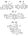
- Fig. 7 is a plan view of a strip ring resonator according to a fifth embodiment.
- a strip ring resonator 221 comprises a pair of parallel coupling line sections 222a, 222b, a C-shaped first side connecting line 223 through which first side ends of the parallel coupling line sections 222a, 222b are connected, a C-shaped second side connecting line 224 through which the other side ends of the parallel coupling line sections 222a, 222b are connected, the input tap coupling line 184, and the output tap coupling line 185.
- Each of the parallel coupling line sections 222a, 222b has a narrow width W3 and an electric length L1, and the parallel coupling line sections 222a, 222b are spaced a narrow distance S1 apart. Therefore, the parallel coupling line sections 222a, 222b are coupled to each other in inductive coupling in cases where microwaves are transmitted in the parallel coupling line sections 222a, 222b.
- a characteristic impedance in the strip loop resonator 221 is determined according to the electric length L E of the microwave resonator 225 and the inductive coupling between the parallel coupling line sections 222a, 222b.
- the strip loop resonator 221 can be minimized even though the electric length L E of the microwave resonator 225 is smaller than a wavelength of the microwaves.
- Fig. 8 is a plan view of a strip ring resonator according to a sixth embodiment.
- a strip ring resonator 231 comprises a pair of parallel coupling line sections 232a, 232b, a C-shaped first side connecting line 233 through which first side ends of the parallel coupling line sections 232a, 232b are connected, a C-shaped second side connecting line 234 through which the other side ends of the parallel coupling line sections 232a, 232b are connected, the input tap coupling line 184, and the output tap coupling line 185.
- the parallel coupling line sections 232a, 232b and the first and second side connecting lines 233, 234 respectively have a narrow width W4, so that a microwave resonator 235 having the narrow width W4 is formed of the lines 232a, 232b, 233, and 234.
- An electric length of the microwave resonator 235 is the same as that of the microwave resonator 225.
- the narrow width W4 is narrower than the width W3 of the microwave resonator 225. Therefore, the inductive coupling between the parallel coupling line sections 232a, 232b is stronger than that between the parallel coupling line sections 222a, 222b shown in Fig. 7. In contrast, capacitive coupling between the parallel coupling line sections 232a, 232b is weaker than that between the parallel coupling line sections 222a, 222b shown in Fig. 7.
- a characteristic impedance in the strip ring resonator 231 is determined according to the electric length L E of the microwave resonator 235 and the inductive coupling between the parallel coupling line sections 232a, 232b, in the same manner as in the resonator 221. Accordingly, the strip ring resonator 231 can be minimized in the same manner as the resonator 221 shown in Fig. 7.
- the line-to-line capacitor 202 be additionally provided to the resonator 221 or 222 to strengthen the capacitive coupling between the parallel coupling line sections 222a, 222b, or the parallel coupling line sections 232a, 232b. Also, it is preferred that a pair of curved coupling lines be provided in place of the straight coupling lines on condition that the curved coupling lines are spaced the distance S1 apart.
- the input and output tap coupling lines 183, 186 are respectively coupled to the first and second side connecting lines in the inductive coupling. However, it is preferred that the input and output tap coupling lines 183, 186 be coupled to the first and second side connecting lines in capacitive coupling. Also, it is preferred that the input and output tap coupling lines 183, 186 be coupled to the parallel coupling line sections 182a, 182b, to 232a, 232b.
- Fig. 9 is a plan view of a band-pass filter in which two microwave resonators 187 shown in Fig. 3 are arranged in series according to a seventh embodiment concept.
- a band-pass filter 241 comprises an input strip line 242 in which microwaves are transmitted, the microwave resonator 187 arranged in a first stage, the microwave resonator 187 arranged in a second stage, an input coupling capacitor 243 for coupling the input strip line 242 to the first-stage microwave resonator 187 in capacitive coupling, an output strip line 244 in which the microwaves resonated in the microwave resonators 187 are transmitted, an output coupling capacitor 245 for coupling the output strip line 242 to the second-stage microwave resonator 187 in capacitive coupling.
- the second side connecting line 184 of the first-stage microwave resonator 187 is coupled to the first side connecting line 183 of the second-stage microwave resonator 187 in inductive coupling. Because the width W2 of the first and second connecting lines 183, 184 is narrow, a type of the electromagnetic coupling between the first and second connecting lines 183, 184 is the inductive coupling.
- each of the microwave resonators 187 functions as a resonator and filter. Therefore, the band-pass filter 241 functions as a four-stage filter.
- the microwave resonators 187 are in rectangular shape, the microwave resonators 187 can be closely coupled to each other. Also, because a large number of rectangle-shaped microwave resonators 187 can be orderly arranged, the band-pass filter 241 can be minimized even though a large number of rectangle-shaped microwave resonators 187 are arranged in series.
- a resonance width of the microwaves in a low band is generally narrowed in cases where the microwaves are transferred in the capacitive coupling
- a resonance width of the microwaves in a high band is generally narrowed in cases where the microwaves are transferred in the inductive coupling.
- the input and output strip lines 242, 244 are coupled to the microwave resonators 187 in the capacitive coupling, and the microwave resonators 187 are coupled to each other in the inductive coupling. Therefore, the resonance width of the microwaves can be narrowed regardless of the frequency of the microwaves.
- the microwave resonators 187 are arranged in series.
- the seventh embodiment is not limited to the microwave resonators 187. That is, it is preferred that the microwave resonators 193, 213, 225, or 235 be arranged in series.
- Fig. 10 is a plan view of a band-pass filter in which two microwave resonators 187 shown in Fig. 3 are arranged in series according to an eighth embodiment.
- a band-pass filter 251 according to the seventh embodiment comprises the input tap coupling line 185, the microwave resonator 187 arranged in a first stage, the microwave resonator 187 arranged in a second stage, and the output strip line 186
- the parallel coupling line sections 182b of the first-stage microwave resonator 187 is coupled to the parallel coupling line section 182a of the second-stage microwave resonator 187 in capacitive coupling. Because the width W1 of the parallel coupling lines 182a, 182b is wide, a type of the electromagnetic coupling between the parallel coupling line sections 182a, 182b is the capacitive coupling.
- each of the microwave resonators 187 functions as a resonator and filter. Therefore, the band-pass filter 251 functions as a four-stage filter.
- the microwave resonators 187 are in rectangular shape, the microwave resonators 187 can be closely coupled to each other. Also, because a large number of rectangle-shaped microwave resonators 187 can be orderly arranged, the band-pass filter 251 can be minimized even though a large number of rectangle-shaped microwave resonators 187 are arranged in series.
- the input and output tap coupling lines 185, 186 are coupled to the microwave resonators 187 in the inductive coupling, and the microwave resonators 187 are coupled to each other in the capacitive coupling. Therefore, a resonance width of the microwaves can be narrowed regardless of the frequency of the microwaves in the band-pass filter 251.
- the microwave resonators 187 are arranged in series.
- the eighth embodiment is not limited to the microwave resonators 187. That is, it is preferred that the microwave resonators 193, 213, 225, or 235 be arranged in series.
Landscapes
- Physics & Mathematics (AREA)
- Electromagnetism (AREA)
- Control Of Motors That Do Not Use Commutators (AREA)
Description
- The present invention relates to a strip ring resonator utilized to resonate waves in frequency bands ranging from an ultra high frequency (UHF) band to a super high frequency (SHF) band, and relates to a band-pass filter composed of a series of resonators which is utilized as a communication equipment or measuring equipment.
- A half-wave length open end type of strip ring resonator has been generally utilized to resonate microwaves ranging from the UHF band to the SHF band. Also, a one-wave length strip ring resonator has been recently known. In the one-wave length strip ring resonator, no open end to reflect the microwaves is required because an electric length of the strip ring resonator is equivalent to one-wave length of the microwaves. Therefore, the microwaves are efficiently resonated because electric energy of the microwaves resonated is not lost in the open end.
- In addition, in cases where a band-pass filter is composed of a plurality of strip ring resonators arranged in series, a strip dual mode ring resonator functioning as a two-stage filter is required to efficiently filter the microwave in the band-pass filter.
- A first conventional resonator is described.
- Fig. 1A is a plan view of a one-wave length strip ring resonator in which no open end is provided. Fig. 1B is a sectional view taken generally along the line I-I of Fig. 1A. Each of constitutional elements of the ring resonator shown in Fig. 1A is illustrated in Fig. 1B.
- As shown in Fig. 1A, a one-wave length
strip ring resonator 11 conventionally utilized is provided with aninput strip line 12 in which microwaves are transmitted, a closed ring-shaped strip line 13 in which the microwaves transferred from theinput strip line 12 are resonated, and anoutput strip line 14 to which the microwaves resonated in thestrip ring 13 are transferred. - As shown in Fig. 1B, the input and
output strip lines shaped strip line 13 respectively consist of a strip conductive plate 15, a dielectric substrate 16 surrounding the strip conductive plate 15, and a pair ofconductive substrates 17a, 17b sandwiching the dielectric substrate 16. - The ring-
shaped strip line 13 has an electric length equivalent to a wavelength of the microwave. The electric length of the ring-shaped strip line 13 is determined by correcting a physical line length of the ring-shaped strip line 13 with a relative dielectric constant εr of the dielectric substrate 16. - The
input strip line 12 is arranged at one side of thestrip ring 13 and is coupled to the ring-shaped strip line 13 in capacitive coupling. That is, when the microwaves transmit through theinput strip line 12, electric field is induced in a gap space between theinput strip line 12 and the ring-shaped strip line 13. Therefore, the intensity of electric field in the ring-shaped strip line 13 is also increased at a coupling point P1 adjacent to theinput strip line 12 to a maximum value. - The
output strip line 14 is arranged at an opposite side of thestrip ring 13. In other words, theoutput strip line 14 is spaced 180 degrees (a half-wave length of the microwaves) in the electric length apart from theinput strip line 12. In this case, the intensity of the electric field in the ring-shaped strip line 13 is maximized at a coupling point P2 adjacent to theoutput strip line 14 because theoutput strip line 14 is spaced 180 degrees in the electric length apart from theinput strip line 12. Therefore, theoutput strip line 14 is electrically coupled to the ring-shaped strip line 13 in capacitive coupling. - In the above configuration, when microwaves are transmitted in the
input strip line 12, electric field is induced at a gap portion between theinput strip line 12 and the ring-shaped strip line 13 by the microwaves. Therefore, the intensity of the electric field in the ring-shaped strip line 13 is maximized at the coupling point P1 adjacent to theinput strip line 12. Thereafter, the electric field induced at the coupling point P1 is diffused into the ring-shaped strip line 13 as traveling waves. In other words, the microwaves are transferred from theinput strip line 12 to the ring-shaped strip line 13. In this case, a part of the travelling waves are transmitted in a clockwise direction, and a remaining part of the travelling waves are transmitted in a counterclockwise direction. In cases where the wavelength of the microwaves is equivalent to the electric length of the ring-shaped strip line 13, the microwaves are resonated in the ring-shaped strip line 13. Therefore, the intensity of the microwaves in the ring-shaped strip line 13 is amplified. - Thereafter, the intensity of the electric field in the ring-
shaped strip line 13 is maximized at the coupling point P2 adjacent to theoutput strip line 14 because theoutput strip line 14 is spaced 180 degrees in the electric length apart from theinput strip line 12. Therefore, the electric field is induced at a gap space between the ring-shaped strip line 13 and theoutput strip line 14. As a result, the microwave resonated in the ring-shaped strip line 13 is transferred to theoutput strip line 14. - Accordingly, the
strip ring resonator 11 functions as a resonator of the microwaves. - In this case, the microwaves can be resonated in the
strip ring 13 even though the electric length of the ring-shaped strip line 13 is an integral multiple of the wavelength of the microwaves. - The
strip ring resonator 11 is often utilized to estimate the dielectric substrate 16 because a resonance frequency (or a central frequency) of the microwaves is shifted according to a physical shape of the dielectric substrate 16 and the relative dielectric constant εr of the dielectric substrate 16. - The
strip ring resonator 11 is described in detail in the literature "Resonant Microstrip Ring Aid Dielectric Material Testing", Microwaves & RF, page 95-102, April, 1991. - A second conventional resonator is described.
- Fig. 2 is a plan view of a strip dual mode ring resonator functioning as a two-stage filter.
- As shown in Fig. 2, a strip dual
mode ring resonator 21 conventionally utilized is provided with aninput strip line 22 in which microwaves are transmitted, a one-wavelength strip ring 23 electrically coupled to theinput strip line 22 in capacitive coupling, and anoutput strip line 24 electrically coupled to thestrip ring 23 in capacitive coupling. - The
input strip line 22 is coupled to thestrip ring 23 through agap capacitor 25, and theoutput strip line 24 is coupled to thestrip ring 23 through agap capacitor 26. Also, theoutput strip line 24 is spaced 90 degrees (or a quarterwave length of the microwaves) in the electric length apart from theinput strip line 22. - The
strip ring 23 has anopen end stub 27 in which the microwaves are reflected. Theopen end stub 27 is spaced 135 degrees (or 3/8-wave length of the microwaves) in the electric length apart from the input andoutput strip lines - In the above configuration, the action of the strip dual
mode ring resonator 21 is qualitatively described in a concept of travelling waves. - When travelling waves are transmitted in the
input strip line 22, electric field is induced in thegap capacitor 25. Therefore, theinput strip line 22 is coupled to thestrip ring 23 in the capacitive coupling, so that a strong intensity of electric field is induced at a point P3 of thestrip ring 23 adjacent to theinput strip line 22. That is, the travelling waves are transferred to the coupling point P3 of thestrip ring 23. Thereafter, the travelling waves are circulated in thestrip ring 23 to diffuse the electric field strongly induced in thestrip ring 23. In this case, a part of the travelling waves are transmitted in a clockwise direction and a remaining part of the travelling waves are transmitted in a counterclockwise direction. - An action of the travelling waves transmitted in the counterclockwise direction is initially described.
- When the travelling waves transmitted in the counterclockwise direction reach a coupling point P4 of the
strip ring 23 adjacent to theoutput line 24, the phase of the travelling wave shifts by 90 degrees. Therefore, the intensity of the electric field at the coupling point P4 is minimized. Accordingly, theoutput strip line 24 is not coupled to thestrip ring 23 so that the travelling waves are not transferred to theoutput strip line 24. - Thereafter, when the travelling waves reach the
open end stub 27, the phase of the travelling wave further shifts by 135 degrees as compared with the phase of the travelling wave reaching the coupling point P4. Because theopen end stub 27 is equivalent to a discontinuous portion of thestrip ring 23, a part of the travelling waves are reflected at theopen end stub 27 to produce reflected waves, and a remaining part of the travelling waves are not reflected at theopen end stub 27 to produce non-reflected waves. - The non-reflected waves are transmitted to the coupling point P3. In this case, because the phase of the non-reflected waves transmitted to the coupling point P3 totally shifts by 360 degrees as compared with that of the travelling waves transferred from the
input strip line 22 to the coupling point P3, the intensity of the electric field at the coupling point P3 is maximized. Therefore, theinput strip line 22 is coupled to thestrip ring 23 so that a part of the non-reflected waves are returned to theinput strip line 22. A remaining part of the non-reflected waves are again circulated in the counterclockwise direction so that the microwaves transferred to thestrip ring 23 are resonated. - In contrast, the reflected waves are returned to the coupling point P4. In this case, the phase of the reflected waves at the point P4 further shifts by 135 degrees as compared with that of the reflected wave at the
open end stub 27. This is, the phase of the reflected wave at the point P4 totally shifts by 360 degrees as compared with that of the travelling waves transferred from theinput strip line 22 to the coupling point P3. Therefore, the intensity of the electric field at the coupling point P4 is maximized, so that theoutput strip line 24 is coupled to thestrip ring 23. As a result, a part of the reflected wave is transferred to theoutput strip line 24. A remaining part of the reflected wave is again circulated in the clockwise direction so that the microwave transferred to thestrip ring 23 is resonated. - Next, the travelling waves transmitted in the clockwise direction is described.
- A part of the travelling waves transmitted in the clockwise direction are reflected at the
open end stub 27 to produce reflected waves when the phase of the travelling waves shifts by 135 degrees. Non-reflected waves formed of a remaining part of the travelling waves reach the coupling point P4. The phase of the non-reflected waves totally shifts by 270 degrees so that the intensity of the electric field induced by the non-reflected waves is minimized. Therefore, the non-reflected waves are not transferred to theoutput strip line 24. That is, a part of the non-reflected waves are transferred from the coupling point P3 to theinput strip line 22 in the same manner, and a remaining part of the non-reflected waves are again circulated in the clockwise direction so that the microwave transferred to thestrip ring 23 is resonated. - In contrast, the reflected waves are returned to the coupling point P3. In this case, because the phase of the reflected waves at the coupling point P3 totally shifts by 270 degrees, the intensity of the electric field induced by the reflected waves are minimized so that the reflected waves are not transferred to the
input strip line 22. Thereafter, the reflected waves reach the coupling point P4. In this case, because the phase of the reflected waves at the coupling point P4 totally shifts by 360 degrees, the intensity of the electric field induced by the reflected waves is maximized. Therefore, a part of the reflected waves are transferred to theoutput strip line 24, and a remaining part of the reflected waves are again circulated in the counterclockwise direction so that the microwaves transferred to thestrip ring 23 are resonated. - Accordingly, because the microwaves can be resonated in the
strip ring 23 on condition that a wavelength of the microwaves equals the electric length of thestrip ring 23, the strip dualmode ring resonator 21 functions as a resonator and a filter. - Also, the microwaves transferred from the
input strip line 22 are initially transmitted in thestrip ring resonator 23 as the non-reflected waves, and the microwaves are again transmitted in thestrip ring resonator 23 as the reflected waves shifting by 90 degrees as compared with the non-reflected waves. In other words, two orthogonal modes formed of the non-reflected waves and the reflected waves independently coexist in thestrip ring resonator 23. Therefore, the stripdual mode filter 21 functions as a dual mode filter. That is, the function of the stripdual mode filter 21 is equivalent to a pair of a single mode filters arranged in series. - In addition, a ratio in the intensity of the reflected waves to the non-reflected waves is changed in proportional to the length of the
open end stub 27 projected in a radial direction of thestrip ring resonator 23. Therefore, the intensity of the reflected microwave transferred to theoutput strip line 24 can be adjusted by trimming theopen end stub 27. - The strip dual
mode ring resonator 21 is proposed by J.A. Curtis "International Microwave Symposium Digest", IEEE, page 443-446(N-1), 1991. - However, there are many drawbacks in the
strip ring resonator 11. That is, it is difficult to manufacture a small-sizedstrip ring resonator 11 because a central portion surrounded by the ring-shapedstrip line 13 is a dead space. Also, the electric length of the ring-shapedstrip line 13 cannot be minutely adjusted after the ring-shapedstrip line 13 is manufactured according to a photo-etching process or the like. In this case, the resonance frequency of the microwaves depends on the electric length of the ring-shapedstrip line 13. Therefore, the resonance frequency of the microwaves cannot be minutely adjusted. In addition, in cases where a plurality ofstrip ring resonators 11 are arranged in series to compose a band-pass filter, it is difficult to couple the ring-shapedstrip lines 13 to each other because the ring-shapedstrip lines 13 are curved. - Also, there are many drawbacks in the
strip ring resonator 21. That is, a central frequency of the microwaves filtered in thestrip ring resonator 21 cannot be minutely adjusted because the central frequency of the microwaves depends on the width of theopen end stub 27 extending in a circumferential direction of thestrip ring 23. Therefore, the central frequency of the microwaves manufactured does not often agree with a designed central frequency. As a result, a yield rate of thestrip ring resonator 21 is lowered. - Also, because a resonance width (or a full width at half maximum) can be adjusted only by trimming the length of the
open end stub 27, the resonance width cannot be enlarged. In other words, in cases where the width of theopen end stub 27 in the circumferential direction is widened to enlarge the resonance width, the phase of the reflected waves reaching theoutput strip line 24 undesirably shifts. As a result, the intensity of the microwaves transferred to theoutput strip line 24 is lowered at the central frequency of the microwaves resonated. Accordingly, in cases where a plurality ofstrip ring resonators 21 are arranged in series to compose a band-pass filter, the filter is limited to a narrow passband type of filter. - The object is to provide a small-sized strip ring resonator in which the resonance frequency is easily and minutely adjusted and the resonance width is narrow, and to provide a band-pass filter composed of the resonators.
- The object is achieved by the provision of a strip ring resonators according to claims 1 and 8 and a band-pass filter as specified in claim 10.
- The objects, features and advantages of the present invention will be apparent from the following description taken in conjunction with the accompanying drawings, in which:
- Fig. 1A is a plan view of a conventional one-wave length type of strip ring resonator in which no open end is provided;
- Fig. 1B is a sectional view taken generally along the line I-I of Fig. 1A;
- Fig. 2 is a plan view of a conventional strip dual mode ring resonator functioning as a two-stage filter;
- Fig. 3 is a plan view of a strip dual mode ring resonator according to a first embodiment;
- Fig. 4 is a plan view of a strip dual mode ring resonator according to a second embodiment;
- Fig. 5 is a plan view of a strip dual mode ring resonator according to a third embodiment;
- Fig. 6 is a plan view of a strip dual mode ring resonator according to a fourth embodiment.
- Fig. 7 is a plan view of a strip dual mode ring resonator according to a fifth embodiment;
- Fig. 8 is a plan view of a strip dual mode ring resonator according to a sixth embodiment;
- Fig. 9 is a plan view of a band-pass filter in which two microwave resonators shown in Fig. 18 are arranged in series according to a seventh embodiment; and
- Fig. 10 is a plan view of a band-pass filter in which the microwave resonators shown in Fig. 18 are arranged in series according to an eighth embodiment .
-
- Preferred embodiments of a ring resonator and a band-pass filter composed of the resonators according to the present invention are described with reference to drawings.
- Fig. 3 is a plan view of a strip ring resonator according to a first embodiment.
- As shown in Fig. 18, a
strip ring resonator 181 comprises a pair of parallelcoupling line sections side connecting line 183 through which first side ends of theparallel coupling lines side connecting line 184 through which the other side ends of the parallelcoupling line sections tap coupling line 185 coupled to the firstside connecting line 183 in inductive coupling, and an outputtap coupling line 186 coupled to the secondside connecting line 184 in inductive coupling. - Each of the parallel
coupling line sections coupling line sections coupling line sections coupling line sections - The first and second
side connecting lines side connecting line 183 are connected to outside portions of theparallel coupling lines side connecting line 184 are connected to the outside portions of the parallelcoupling line sections - Therefore, a rectangular shape of
microwave resonator 187 is formed of the parallelcoupling line sections side connecting lines microwave resonator 187 sums up to LE = 2*L1 + 2*L2. Also, both ends of the firstside connecting line 183 are not coupled to each other so much in cases where microwaves are transmitted in the firstside connecting line 183. Also, both ends of the secondside connecting line 184 are not coupled to each other so much in the same manner. - In the above configuration, microwaves having various wavelengths around a resonance microwave λo are transferred from the input
tap coupling line 185 to the firstside connecting line 183 because the inputtap coupling line 185 is coupled to the firstside connecting line 183 in the inductive coupling. Thereafter, the microwaves transferred to theline 183 are circulated in themicrowave resonator 187 in clockwise and counterclockwise directions, according to the characteristic impedance of themicrowave resonator 187. The characteristic impedance of themicrowave resonator 187 depends on the electric length LE of themicrowave resonator 187, a line impedance of themicrowave resonator 187, and the capacitive coupling between the parallelcoupling line sections coupling line sections coupling line sections - In cases where the wavelength of the microwaves agrees with the resonance wavelength λo of the microwaves, the microwaves are resonated in the
microwave resonator 187. The resonance wavelength λo of the microwaves resonated in themicrowave resonator 187 is longer than the electric length LE of themicrowave resonator 187 because the parallelcoupling line sections coupling line sections coupling line sections parallel coupling lines - In addition, an unloaded quality factor Q in a resonance circuit is generally defined according to an equation Q = ωo*C*R, where the symbol R denotes a resistance in the resonance circuit. Therefore, the unloaded quality factor Q is increased in proportion as the capacitive coupling between the parallel
coupling line sections coupling line sections - Thereafter, the microwaves resonated in the
microwave resonator 187 are transferred to the outputtap coupling line 186 because themicrowave resonator 187 is coupled to theline 186 in the inductive coupling. - Accordingly, even though the wavelength of the microwaves is longer than the electric length LE of the
microwave resonator 187, the microwaves can be resonated in thestrip ring resonator 181. In other words, because the microwaves can be resonated even though the wavelength of the microwaves is longer than the electric length LE, the electric length LE of themicrowave resonator 187 can be shortened. That is, thestrip ring resonator 181 can be minimized regardless of the wavelength of the microwaves. - For example, on condition that a relative dielectric constant is εr=2.2, a thickness of the
microwave resonator 187 is H1=10 mm, the electric length of the parallelcoupling line sections side connecting lines parallel coupling lines side connecting lines coupling line sections - Also, the resonance wavelength λo of the microwaves can be minutely adjusted by changing the width W1 of the parallel
coupling line sections coupling line sections coupling line sections coupling line sections - Also, because the unloaded quality factor Q is increased depending on the strength of the capacitive coupling between the parallel
coupling line sections strip loop resonator 181 in which the resonance width is narrowed can be manufactured. - Also, in cases where the
strip ring resonator 181 is utilized as a resonator in an oscillating circuit, an output signal of the oscillating circuit can stably have an oscillated band of which a frequency range is narrowed. Therefore, superior phase-noise characteristics can be obtained in the oscillated circuit in which thestrip ring resonator 181 is utilized. - Also, because the
strip ring resonator 181 is in rectangular shape, a plurality ofresonators 181 can be closely arranged in series. - Next, a second embodiment according to the present invention is described.
- Fig. 4 is a plan view of a strip ring resonator according to a second embodiment.
- As shown in Fig. 4, a
strip ring resonator 191 comprises a pair of parallelcoupling line sections side connecting line 183 through which first side ends of the parallelcoupling line sections side connecting line 184 through which the other side ends of the parallelcoupling line sections tap coupling line 184, and the outputtap coupling line 186. - The
parallel coupling lines lines coupling line sections parallel coupling lines coupling line sections coupling line sections lines lines - The parallel
coupling line sections microwave resonator 193 is formed of the parallelcoupling line sections side connecting lines microwave resonator 193 sums up to LE = 2*L1 + 2*L2. - In the above configuration, microwaves having various wavelength around a resonance wavelength λo are transferred from the input
tap coupling line 185 to the firstside connecting line 183 in the same manner as in thestrip ring resonator 181. - Thereafter, the microwaves transferred to the
line 183 are circulated in themicrowave resonator 193 in clockwise and counterclockwise directions, according to the characteristic impedance of themicrowave resonator 193. The characteristic impedance of themicrowave resonator 193 depends on the electric length LE of themicrowave resonator 193, a line impedance of themicrowave resonator 193, and the capacitive coupling between theparallel coupling lines parallel coupling lines parallel coupling lines lines - In cases where the wavelength of the microwaves agrees with the resonance wavelength λo of the microwaves, the microwaves are resonated in the microwave resonator 192. The resonance wavelength λo of the microwaves resonated in the microwave resonator 192 is longer than the electric length LE of the
microwave resonator 187, in the same reason as in thestrip ring resonator 181. Also, a resonance width of the microwaves is narrowed in proportion as the capacitive coupling between the parallelcoupling line sections strip ring resonator 181. - Thereafter, the microwaves resonated in the
microwave resonator 193 are transferred to the outputtap coupling line 186. - Accordingly, because the capacitive coupling between the parallel
coupling line sections coupling line sections strip ring resonator 191 can be greatly minimized regardless of the wavelength of the microwaves as compared with thestrip ring resonator 181. - Also, the resonance wavelength λo of the microwaves can be minutely adjusted by changing the shape of the curved inside surfaces of the parallel
coupling line sections parallel coupling lines - Also, the
strip ring resonator 191 in which the resonance width is narrowed can be manufactured in the same reason as in thestrip ring resonator 181. - Also, in cases where the
strip ring resonator 191 is utilized as a resonator in an oscillating circuit, superior phase-noise characteristics can be obtained in the oscillated circuit in which thestrip ring resonator 191 is utilized. - Also, because the
strip ring resonator 191 is in rectangular shape, a plurality ofresonators 181 can be closely arranged in series. - Next, a third embodiment according to the present invention is described.
- Fig. 5 is a plan view of a strip ring resonator according to a third embodiment.
- As shown in Fig. 5, a
strip ring resonator 201 comprises theparallel coupling lines side connecting line 183, the secondside connecting line 184, the inputtap coupling line 184, the outputtap coupling line 185, and a line-to-line coupling capacitor 202 arranged between the parallelcoupling line sections - The line-to-
line coupling capacitor 202 is formed of a plate capacitor or a chip capacitor, and has a lumped capacitance Cw. - In the above configuration, because the line-to-
line coupling capacitor 202 is arranged between the parallelcoupling line sections strip ring resonator 201 is additionally changed by thecapacitor 202 as compared with that in thestrip ring resonator 181. - Accordingly, the
strip ring resonator 201 can be greatly minimized regardless of a wavelength of microwaves as compared with thestrip ring resonator 181. - Also, a resonance wavelength λo of the microwaves can be minutely adjusted by changing the lumped capacitance Cw of the
capacitor 202. The lumped capacitance Cw of thecapacitor 202 is, for example, changed by trimming both plates of thecapacitor 202 after thestrip ring resonator 191 is manufactured. - In the third embodiment, the
capacitor 202 is additionally provided to theresonator 181. However, it is preferred that thecapacitor 202 be additionally provided to theresonator 191. In this case, thestrip ring resonator 201 can be greatly minimized as compared with thestrip ring resonator 191. - Also, the
capacitor 202 is positioned in the center of each of the parallelcoupling line sections capacitor 202 is not limited to the center of each of the parallelcoupling line sections capacitor 202 be positioned adjacent to the firstside connecting line 183 or be positioned adjacent to the secondside connecting lint 184. - Next, a fourth embodiment according to the present invention is described.
- Fig. 6 is a plan view of a strip ring resonator according to a fourth embodiment.
- As shown in Fig. 6, a
strip ring resonator 211 comprises the parallelcoupling line sections side connecting line 212 through which first side ends of the parallelcoupling line sections side connecting line 213 through which the other side ends of the parallelcoupling line sections tap coupling line 184, and the outputtap coupling line 185. - The first and second
side connecting lines side connecting line 212 are connected to the inside portions of the parallelcoupling line sections side connecting line 213 are connected to the inside portions of the parallelcoupling line sections microwave resonator 214 is formed of the parallelcoupling line sections side connecting lines microwave resonator 214 sums up to LE = 2*L1 + 2*L3. - Because the both ends of the first
side connecting line 212 are approached to each other, and because the firstside connecting line 212 has the narrow width W2, both ends of the firstside connecting line 212 are coupled to each other in inductive coupling. Also, both ends of the secondside connecting line 213 are coupled to each other in inductive coupling in the same reason. - In the above configuration, a characteristic impedance in the
strip ring resonator 211 is additionally changed by the first and secondside connecting lines strip ring resonator 181. - Accordingly, the
strip ring resonator 211 can be greatly minimized regardless of a wavelength of microwaves as compared with thestrip ring resonator 181. - Next, a fifth embodiment according to the present invention is described.
- Fig. 7 is a plan view of a strip ring resonator according to a fifth embodiment.
- As shown in Fig. 7, a
strip ring resonator 221 comprises a pair of parallelcoupling line sections side connecting line 223 through which first side ends of the parallelcoupling line sections side connecting line 224 through which the other side ends of the parallelcoupling line sections tap coupling line 184, and the outputtap coupling line 185. - Each of the parallel
coupling line sections coupling line sections coupling line sections coupling line sections - The first and second
side connecting lines side connecting line 223 are connected to the parallelcoupling line sections side connecting line 224 are connected to the parallelcoupling line sections microwave resonator 225 is formed of the parallelcoupling line sections side connecting lines microwave resonator 225 sums up to LE = 2*L1 + 2*L2. Also, both ends of the firstside connecting line 223 are not coupled to each other so much in cases where microwaves are transmitted in the firstside connecting line 223. Also, both ends of the secondside connecting line 224 are not coupled to each other so much in the same manner. - In the above configuration, a characteristic impedance in the
strip loop resonator 221 is determined according to the electric length LE of themicrowave resonator 225 and the inductive coupling between the parallelcoupling line sections - Accordingly, the
strip loop resonator 221 can be minimized even though the electric length LE of themicrowave resonator 225 is smaller than a wavelength of the microwaves. - Next, a sixth embodiment according to the present invention is described.
- Fig. 8 is a plan view of a strip ring resonator according to a sixth embodiment.
- As shown in Fig. 8, a
strip ring resonator 231 comprises a pair of parallelcoupling line sections side connecting line 233 through which first side ends of the parallelcoupling line sections side connecting line 234 through which the other side ends of the parallelcoupling line sections tap coupling line 184, and the outputtap coupling line 185. - The parallel
coupling line sections side connecting lines lines microwave resonator 225. The narrow width W4 is narrower than the width W3 of themicrowave resonator 225. Therefore, the inductive coupling between the parallelcoupling line sections coupling line sections coupling line sections coupling line sections - In the above configuration, a characteristic impedance in the
strip ring resonator 231 is determined according to the electric length LE of the microwave resonator 235 and the inductive coupling between the parallelcoupling line sections resonator 221. Accordingly, thestrip ring resonator 231 can be minimized in the same manner as theresonator 221 shown in Fig. 7. - In the fifth to sixth embodiments, it is preferred that the line-to-
line capacitor 202 be additionally provided to theresonator 221 or 222 to strengthen the capacitive coupling between the parallelcoupling line sections coupling line sections - In the first to sixth embodiments the input and output
tap coupling lines tap coupling lines tap coupling lines coupling line sections - Next, a seventh embodiment according to the present invention is described.
- Fig. 9 is a plan view of a band-pass filter in which two
microwave resonators 187 shown in Fig. 3 are arranged in series according to a seventh embodiment concept. - As shown in Fig. 9, a band-
pass filter 241 according to the seventh embodiment comprises aninput strip line 242 in which microwaves are transmitted, themicrowave resonator 187 arranged in a first stage, themicrowave resonator 187 arranged in a second stage, aninput coupling capacitor 243 for coupling theinput strip line 242 to the first-stage microwave resonator 187 in capacitive coupling, an output strip line 244 in which the microwaves resonated in themicrowave resonators 187 are transmitted, an output coupling capacitor 245 for coupling theoutput strip line 242 to the second-stage microwave resonator 187 in capacitive coupling. - The second
side connecting line 184 of the first-stage microwave resonator 187 is coupled to the firstside connecting line 183 of the second-stage microwave resonator 187 in inductive coupling. Because the width W2 of the first and second connectinglines lines - In the above configuration, when microwaves are circulated in the first-
stage microwave resonator 187, a magnetic field is strongly induced around the second connectingline 184 of the first-stage microwave resonator 187 so that microwaves are induced by the magnetic field in the first connectingline 183 of the second-stage microwave resonator 187. Thereafter, the microwaves are circulated in the second-stage microwave resonator 187, and the microwaves are transferred to the output strip line 244. In this case, each of themicrowave resonators 187 functions as a resonator and filter. Therefore, the band-pass filter 241 functions as a four-stage filter. - Accordingly, because the
microwave resonators 187 are in rectangular shape, themicrowave resonators 187 can be closely coupled to each other. Also, because a large number of rectangle-shapedmicrowave resonators 187 can be orderly arranged, the band-pass filter 241 can be minimized even though a large number of rectangle-shapedmicrowave resonators 187 are arranged in series. - Also, a resonance width of the microwaves in a low band is generally narrowed in cases where the microwaves are transferred in the capacitive coupling, and a resonance width of the microwaves in a high band is generally narrowed in cases where the microwaves are transferred in the inductive coupling. In the band-
pass filter 241, the input andoutput strip lines 242, 244 are coupled to themicrowave resonators 187 in the capacitive coupling, and themicrowave resonators 187 are coupled to each other in the inductive coupling. Therefore, the resonance width of the microwaves can be narrowed regardless of the frequency of the microwaves. - In the seventh embodiment , the
microwave resonators 187 are arranged in series. However, the seventh embodiment is not limited to themicrowave resonators 187. That is, it is preferred that themicrowave resonators - Next, an eighth embodiment according to the present invention is described.
- Fig. 10 is a plan view of a band-pass filter in which two
microwave resonators 187 shown in Fig. 3 are arranged in series according to an eighth embodiment. - As shown in Fig. 10, a band-
pass filter 251 according to the seventh embodiment comprises the inputtap coupling line 185, themicrowave resonator 187 arranged in a first stage, themicrowave resonator 187 arranged in a second stage, and theoutput strip line 186 - The parallel
coupling line sections 182b of the first-stage microwave resonator 187 is coupled to the parallelcoupling line section 182a of the second-stage microwave resonator 187 in capacitive coupling. Because the width W1 of theparallel coupling lines coupling line sections - In the above configuration, when microwaves are circulated in the first-
stage microwave resonator 187, electric field is strongly induced around the parallelcoupling line section 182b of the first-stage microwave resonator 187 so that microwaves are induced by the electric field in the parallelcoupling line section 182a of the second-stage microwave resonator 187. Thereafter, the microwaves are circulated in the second-stage microwave resonator 187, and the microwaves are transferred to the outputtap coupling line 186. In this case, each of themicrowave resonators 187 functions as a resonator and filter. Therefore, the band-pass filter 251 functions as a four-stage filter. - Accordingly, because the
microwave resonators 187 are in rectangular shape, themicrowave resonators 187 can be closely coupled to each other. Also, because a large number of rectangle-shapedmicrowave resonators 187 can be orderly arranged, the band-pass filter 251 can be minimized even though a large number of rectangle-shapedmicrowave resonators 187 are arranged in series. - Also, the input and output
tap coupling lines microwave resonators 187 in the inductive coupling, and themicrowave resonators 187 are coupled to each other in the capacitive coupling. Therefore, a resonance width of the microwaves can be narrowed regardless of the frequency of the microwaves in the band-pass filter 251. - In the eighth embodiment, the
microwave resonators 187 are arranged in series. However, the eighth embodiment is not limited to themicrowave resonators 187. That is, it is preferred that themicrowave resonators
Claims (16)
- A strip ring resonator (181) in which a microwave is resonated, comprising:a rectangle-shaped ring strip line having an electric length shorter than a wavelength of the microwave for resonating the microwave circulated therein in two different directions according to a line impedance thereof, the rectangle-shaped strip line comprising
a pair of parallel coupling line sections (182a,b) respectively having a wide width which are capacitively coupled to each other to change a characteristic impedance of the strip line,
a first side strip line through which first side ends of the parallel line sections (182a,b) are connected, the first side strip line having a narrow width narrower than the wide width of the parallel coupling line sections (182a,b), and
a second side strip line through which second side ends of the parallel line sections (182a,b) are connected, the second side strip line having another narrow width narrower than the wide width of the parallel coupling lines,
an input strip line coupled to the rectangle-shaped ring strip line in electromagnetic coupling, the microwave being transferred from the input strip line to the rectangle-shaped ring strip line; and
an output strip line coupled to the rectangle-shaped ring strip line in electromagnetic coupling, the microwave being transferred from the rectangle-shaped strip line to the output strip line. - A resonator according to claim 1 in which the parallel coupling line sections of the rectangle-shaped ring strip line have curved inside surfaces facing each other to strengthen the capacitive coupling between the parallel coupling lines, the curved inside surfaces being spaced a narrow distance apart.
- A resonator according to claim 1 in which a line-to-line capacitor (Cw) having a lumped capacitance is arranged between the parallel coupling line sections of the rectangle-shaped strip line to change a characteristic impedance of the rectangle-shaped ring strip line.
- A resonator according to claim 3 in which one end of the line-to-line capacitor (Cw) being connected to a central portion of one of the parallel coupling lines, and another end of the line-to-line capacitor being connected to a central portion of the other parallel coupling line.
- A resonator according to claim 1 in which both ends of the first and second side strip lines are connected to inside portions of the parallel coupling line sections of the rectangle-shaped ring strip line, the inside portions of the parallel coupling lines facing each other.
- A resonator according to claim 1 in which the input strip line is coupled to the first side strip line in conductive coupling, and the output strip line is coupled to the second side strip line in the conductive coupling.
- A resonator according to claim 1 in which the input strip line is coupled to the first side strip line in inductive coupling, and the output strip line is coupled to the second side strip line in the inductive coupling.
- A strip ring resonator (221) in which a microwave is resonated, comprising:a loop-shaped strip line having an electric length shorter than a wavelength of the microwave for resonating the microwave circulated therein in two different directions according to a line impedance thereof, the loop-shaped strip line comprising
a pair of parallel coupling line sections (222a, 222b) respectively having a narrow width which are arranged in parallel to each other and
are coupled to each other in inductive coupling to change a characteristic impedance of the loop-shaped strip line,
a first side strip line (223) through which first side ends of the parallel line sections (222a,b) are connected, the first side strip line having the narrow width, and
a second side strip line (224) through which second side ends of the parallel lines are connected, the second side strip line having the narrow width,
an input strip line coupled to the loop-shaped strip line in electromagnetic coupling, the microwave being transferred from the input strip line to the loop-shaped strip line; and
an output strip line coupled to the loop-shaped strip line in electromagnetic coupling, the microwave being transferred from the loop-shaped strip line to the output strip line. - A resonator according to claim 8 in which the parallel coupling lines of the loop-shaped strip line are curved to face each other at a narrow distance to strengthen the inductive coupling between the parallel coupling lines.
- A band-pass filter (241) for filtering a microwave, comprising:a plurality of rectangle-shaped ring strip lines (187) coupled in series which each comprise a pair of parallel coupling line sections respectively having a wide width which are arranged in parallel to each other and are coupled to each other in capacitive coupling to change a characteristic impedance of the rectangle-shaped ring strip line, a first side strip line having a narrow width through which first side ends of the parallel lines are connected, and a second side strip line having another narrow width through which second side ends of the parallel lines are connected, each of the rectangle-shaped ring strip lines having an electric length shorter than a wavelength of the microwave to resonate the microwave circulated therein in two different directions according to a line impedance thereof;an input strip line (242) coupled to the rectangle-shaped strip line in a first stage, the microwave being transferred from the input strip line to the rectangle-shaped strip line in the first stage; andan output strip line coupled to the rectangle-shaped strip line in a final stage, the microwave being transferred from the rectangle-shaped strip line in the final stage to the output strip line.
- A filter according to claim 10 in which one of the parallel coupling line sections of the rectangle-shaped ring strip line in an upper stage is coupled to one of the parallel coupling line sections of the rectangle-shaped ring strip line in a lower stage in capacitive coupling.
- A filter according to claim 11 in which the input and output strip lines are coupled to the rectangle-shaped strip lines in inductive coupling.
- A filter according to claim 10 in which the second side strip line of the rectangle-shaped strip line in an upper stage is coupled to the first side strip line of the rectangle-shaped strip line in a lower stage in inductive coupling.
- A filter according to claim 13 in which the input and output strip lines are coupled to the rectangle-shaped strip lines in capacitive coupling.
- A filter according to claim 10 in which the parallel coupling lines of each of the rectangle-shaped strip lines have curved inside surfaces facing each other to strengthen the capacitive coupling between the parallel coupling lines, the curved inside surfaces being spaced a narrow distance apart.
- A resonator according to claim 10 in which a line-to-line capacitor having a lumped capacitance is arranged between the parallel coupling line section of each of the rectangle-shaped ring strip lines to change a characteristic impedance of the rectangle-shaped strip lines.
Applications Claiming Priority (13)
| Application Number | Priority Date | Filing Date | Title |
|---|---|---|---|
| JP111127/92 | 1992-04-30 | ||
| JP11112792A JPH0637520A (en) | 1992-04-30 | 1992-04-30 | Strip line band-pass filter |
| JP11112792 | 1992-04-30 | ||
| JP117111/92 | 1992-05-11 | ||
| JP11711192A JP2888027B2 (en) | 1992-05-11 | 1992-05-11 | Stripline loop resonator filter |
| JP11711192 | 1992-05-11 | ||
| JP4153238A JP2591402B2 (en) | 1992-06-12 | 1992-06-12 | Microwave resonator and filter circuit using the resonator |
| JP153238/92 | 1992-06-12 | ||
| JP15323892 | 1992-06-12 | ||
| JP24437492A JP2906857B2 (en) | 1992-09-14 | 1992-09-14 | Stripline dual mode filter |
| JP244374/92 | 1992-09-14 | ||
| JP24437492 | 1992-09-14 | ||
| EP93106999A EP0571777B1 (en) | 1992-04-30 | 1993-04-29 | Stripline dual mode ring resonator and band-pass filter composed thereof. |
Related Parent Applications (2)
| Application Number | Title | Priority Date | Filing Date |
|---|---|---|---|
| EP93106999.1 Division | 1993-04-29 | ||
| EP93106999A Division EP0571777B1 (en) | 1992-04-30 | 1993-04-29 | Stripline dual mode ring resonator and band-pass filter composed thereof. |
Publications (3)
| Publication Number | Publication Date |
|---|---|
| EP0730318A2 EP0730318A2 (en) | 1996-09-04 |
| EP0730318A3 EP0730318A3 (en) | 1996-09-11 |
| EP0730318B1 true EP0730318B1 (en) | 2002-08-28 |
Family
ID=27469882
Family Applications (3)
| Application Number | Title | Priority Date | Filing Date |
|---|---|---|---|
| EP93106999A Expired - Lifetime EP0571777B1 (en) | 1992-04-30 | 1993-04-29 | Stripline dual mode ring resonator and band-pass filter composed thereof. |
| EP96107583A Expired - Lifetime EP0730318B1 (en) | 1992-04-30 | 1993-04-29 | Strip dual mode loop resonator for resonating microwave in dual mode and band-pass filter composed of the resonators |
| EP96107582A Expired - Lifetime EP0731521B1 (en) | 1992-04-30 | 1993-04-29 | Strip dual mode ring resonator and band-pass filter composed of the resonators |
Family Applications Before (1)
| Application Number | Title | Priority Date | Filing Date |
|---|---|---|---|
| EP93106999A Expired - Lifetime EP0571777B1 (en) | 1992-04-30 | 1993-04-29 | Stripline dual mode ring resonator and band-pass filter composed thereof. |
Family Applications After (1)
| Application Number | Title | Priority Date | Filing Date |
|---|---|---|---|
| EP96107582A Expired - Lifetime EP0731521B1 (en) | 1992-04-30 | 1993-04-29 | Strip dual mode ring resonator and band-pass filter composed of the resonators |
Country Status (3)
| Country | Link |
|---|---|
| US (4) | US5369383A (en) |
| EP (3) | EP0571777B1 (en) |
| DE (3) | DE69319382T2 (en) |
Families Citing this family (36)
| Publication number | Priority date | Publication date | Assignee | Title |
|---|---|---|---|---|
| DE69319382T2 (en) * | 1992-04-30 | 1999-01-07 | Matsushita Electric Ind Co Ltd | Dual mode stripline ring resonator and bandpass filter with such resonators |
| US5400002A (en) * | 1992-06-12 | 1995-03-21 | Matsushita Electric Industrial Co., Ltd. | Strip dual mode filter in which a resonance width of a microwave is adjusted and dual mode multistage filter in which the strip dual mode filters are arranged in series |
| JPH0856107A (en) * | 1994-08-11 | 1996-02-27 | Matsushita Electric Ind Co Ltd | Dual mode resonator |
| US6239674B1 (en) * | 1993-12-27 | 2001-05-29 | Matsushita Electric Industrial Co., Ltd | Elliptical resonator with an input/output capacitive gap |
| US5587690A (en) * | 1994-08-11 | 1996-12-24 | Matsushita Electric Industrial Co., Ltd. | Ring resonator oscillator usable in frequency synthesizers and communication apparatus |
| US6653914B2 (en) * | 1994-08-31 | 2003-11-25 | Siemens Aktiengesellschaft | RF strip line resonator with a curvature dimensioned to inductively cancel capacitively caused displacements in resonant frequency |
| DE19821382A1 (en) * | 1998-05-13 | 1999-11-25 | Bosch Gmbh Robert | Method for adjusting the resonance frequency of a ring resonator |
| DE19831161A1 (en) * | 1998-07-11 | 2000-01-27 | Bosch Gmbh Robert | Dual mode ring resonator |
| DE19943958A1 (en) * | 1999-09-14 | 2001-03-15 | Bosch Gmbh Robert | Method for balancing the bandwidth of a dual mode filter |
| JP3395753B2 (en) | 2000-02-24 | 2003-04-14 | 株式会社村田製作所 | Method of manufacturing bandpass filter and bandpass filter |
| JP3395754B2 (en) * | 2000-02-24 | 2003-04-14 | 株式会社村田製作所 | Dual-mode bandpass filter |
| JP3575378B2 (en) * | 2000-03-13 | 2004-10-13 | 株式会社村田製作所 | Frequency adjustment method of attenuation pole of dual mode bandpass filter |
| JP3587139B2 (en) | 2000-07-12 | 2004-11-10 | 株式会社村田製作所 | Dual-mode bandpass filter |
| JP3804481B2 (en) * | 2000-09-19 | 2006-08-02 | 株式会社村田製作所 | Dual mode bandpass filter, duplexer, and wireless communication device |
| US6792299B2 (en) * | 2001-03-21 | 2004-09-14 | Conductus, Inc. | Device approximating a shunt capacitor for strip-line-type circuits |
| JP3647806B2 (en) * | 2001-12-26 | 2005-05-18 | 松下電器産業株式会社 | A / D converter, A / D conversion method and signal processing apparatus |
| JP4496516B2 (en) * | 2002-01-31 | 2010-07-07 | ルネサスエレクトロニクス株式会社 | High frequency wiring |
| US6617942B1 (en) * | 2002-02-15 | 2003-09-09 | Northrop Grumman Corporation | Hybrid multi-pole gain zero filter element |
| JP2004032079A (en) * | 2002-06-21 | 2004-01-29 | Hitachi Kokusai Electric Inc | Filter circuit and transmitter and receiver employing filter circuit |
| US6894584B2 (en) | 2002-08-12 | 2005-05-17 | Isco International, Inc. | Thin film resonators |
| US6825742B1 (en) | 2002-12-30 | 2004-11-30 | Raytheon Company | Apparatus and methods for split-feed coupled-ring resonator-pair elliptic-function filters |
| US20040214605A1 (en) * | 2003-04-28 | 2004-10-28 | Zhang Da Ming | Adaptable multi-band antenna system |
| TW200737586A (en) * | 2006-03-31 | 2007-10-01 | Hon Hai Prec Ind Co Ltd | Band-pass filter |
| JP2007281601A (en) * | 2006-04-03 | 2007-10-25 | Toshiba Corp | Filter circuit and method for adjusting characteristics thereof |
| US8314740B2 (en) * | 2007-09-06 | 2012-11-20 | Deka Products Limited Partnership | RFID system |
| TW200933971A (en) * | 2008-01-25 | 2009-08-01 | Univ Nat Taiwan | Filter device with transmission zero |
| US8081852B2 (en) * | 2009-01-21 | 2011-12-20 | Nanyang Technological University | Two-ring optical buffer |
| US9711833B1 (en) * | 2013-01-31 | 2017-07-18 | Physical Optics Corporation | Tunable RF anti-jamming system (TRAJS) |
| CN103107391A (en) * | 2013-02-05 | 2013-05-15 | 南通大学 | Compact type microwave distributed double module band-pass filter |
| TWI568079B (en) * | 2015-07-17 | 2017-01-21 | 緯創資通股份有限公司 | Antenna array |
| FR3043800B1 (en) * | 2015-11-16 | 2018-09-14 | Commissariat A L'energie Atomique Et Aux Energies Alternatives | DEVICE FOR MODULATING THE INTENSITY OF AN OPTICAL SIGNAL ON FOUR DIFFERENT LEVELS |
| CN105963955B (en) * | 2016-06-03 | 2017-12-26 | 江苏科技大学 | A kind of alpine skiing plate release unit |
| RU2662058C1 (en) * | 2017-06-26 | 2018-07-23 | Российская Федерация, от имени которой выступает Министерство обороны Российской Федерации | Microvawe low-pass filter |
| CN111477999A (en) * | 2020-03-17 | 2020-07-31 | 北京邮电大学 | IPD millimeter wave band-pass filter chip of ladder impedance coupling dual-mode resonator |
| CN112072238B (en) * | 2020-07-31 | 2022-01-28 | 南京邮电大学 | Hairpin-type band-pass filter |
| CN113745778B (en) * | 2021-09-03 | 2022-03-29 | 合肥工业大学 | Preparation method of dual-band polarization sensitive band-stop filter |
Family Cites Families (24)
| Publication number | Priority date | Publication date | Assignee | Title |
|---|---|---|---|---|
| US3796970A (en) * | 1973-04-04 | 1974-03-12 | Bell Telephone Labor Inc | Orthogonal resonant filter for planar transmission lines |
| US3967223A (en) * | 1974-02-19 | 1976-06-29 | Westinghouse Electric Corporation | Resonant ring transmission line having a high Q mode |
| JPS5566101A (en) * | 1978-11-13 | 1980-05-19 | Sony Corp | Microwave circuit |
| FR2460049A1 (en) * | 1979-06-25 | 1981-01-16 | Labo Electronique Physique | BANDWHEEL FILTER FOR A HYPERFREQUENCY TRANSMISSION LINE AND A MICROWAVE TRANSISTOR POLARIZATION CIRCUIT COMPRISING THE FILTER |
| US4371853A (en) * | 1979-10-30 | 1983-02-01 | Matsushita Electric Industrial Company, Limited | Strip-line resonator and a band pass filter having the same |
| US4327342A (en) * | 1980-07-10 | 1982-04-27 | U.S. Philips Corporation | Bandstop filter for very high frequency transmission lines and biassing circuit for a very high frequency transistor comprising this filter |
| US4488131A (en) * | 1983-02-25 | 1984-12-11 | Hughes Aircraft Company | MIC Dual mode ring resonator filter |
| JPS60244101A (en) * | 1984-05-18 | 1985-12-04 | Hitachi Ltd | Microstrip filter |
| JPS60253302A (en) * | 1984-05-30 | 1985-12-14 | Nec Corp | Ring-shaped filter |
| JPS61251203A (en) * | 1985-04-29 | 1986-11-08 | Nec Corp | Tri-plate band-pass filter |
| JPS62298202A (en) * | 1986-06-18 | 1987-12-25 | Matsushita Electric Ind Co Ltd | Ring type resonator |
| GB2222312B (en) * | 1988-08-04 | 1993-05-26 | Matsushita Electric Ind Co Ltd | A resonator and a filter including the same |
| SU1712988A1 (en) * | 1989-12-12 | 1992-02-15 | Московский институт связи | Superhigh-frequency rejection filter |
| US5313662A (en) * | 1990-07-26 | 1994-05-17 | Motorola, Inc. | Split-ring resonator bandpass filter with adjustable zero |
| US5017897A (en) * | 1990-08-06 | 1991-05-21 | Motorola, Inc. | Split ring resonator bandpass filter with differential output |
| US5136268A (en) * | 1991-04-19 | 1992-08-04 | Space Systems/Loral, Inc. | Miniature dual mode planar filters |
| US5164690A (en) * | 1991-06-24 | 1992-11-17 | Motorola, Inc. | Multi-pole split ring resonator bandpass filter |
| JPH0575316A (en) * | 1991-09-10 | 1993-03-26 | Fujitsu Ltd | Ring resonator |
| US5172084A (en) * | 1991-12-18 | 1992-12-15 | Space Systems/Loral, Inc. | Miniature planar filters based on dual mode resonators of circular symmetry |
| DE69319382T2 (en) * | 1992-04-30 | 1999-01-07 | Matsushita Electric Ind Co Ltd | Dual mode stripline ring resonator and bandpass filter with such resonators |
| JP2888027B2 (en) * | 1992-05-11 | 1999-05-10 | 松下電器産業株式会社 | Stripline loop resonator filter |
| US5400002A (en) * | 1992-06-12 | 1995-03-21 | Matsushita Electric Industrial Co., Ltd. | Strip dual mode filter in which a resonance width of a microwave is adjusted and dual mode multistage filter in which the strip dual mode filters are arranged in series |
| US5361050A (en) * | 1993-07-06 | 1994-11-01 | Motorola, Inc. | Balanced split ring resonator |
| DE69418127T2 (en) * | 1993-10-04 | 1999-10-14 | Matsushita Electric Ind Co Ltd | Filter and two-mode resonator using stripline technology |
-
1993
- 1993-04-29 DE DE69319382T patent/DE69319382T2/en not_active Expired - Fee Related
- 1993-04-29 DE DE69332249T patent/DE69332249T2/en not_active Expired - Fee Related
- 1993-04-29 EP EP93106999A patent/EP0571777B1/en not_active Expired - Lifetime
- 1993-04-29 EP EP96107583A patent/EP0730318B1/en not_active Expired - Lifetime
- 1993-04-29 US US08/053,535 patent/US5369383A/en not_active Expired - Lifetime
- 1993-04-29 EP EP96107582A patent/EP0731521B1/en not_active Expired - Lifetime
- 1993-04-29 DE DE69332250T patent/DE69332250T2/en not_active Expired - Fee Related
-
1994
- 1994-11-28 US US08/348,169 patent/US5497131A/en not_active Expired - Fee Related
-
1995
- 1995-10-26 US US08/548,841 patent/US5623238A/en not_active Expired - Lifetime
-
1996
- 1996-11-27 US US08/757,791 patent/US5703546A/en not_active Expired - Fee Related
Also Published As
| Publication number | Publication date |
|---|---|
| EP0571777A1 (en) | 1993-12-01 |
| US5497131A (en) | 1996-03-05 |
| DE69332249D1 (en) | 2002-10-02 |
| EP0571777B1 (en) | 1998-07-01 |
| DE69332249T2 (en) | 2003-04-10 |
| US5623238A (en) | 1997-04-22 |
| US5703546A (en) | 1997-12-30 |
| DE69332250D1 (en) | 2002-10-02 |
| US5369383A (en) | 1994-11-29 |
| EP0730318A2 (en) | 1996-09-04 |
| DE69332250T2 (en) | 2003-04-30 |
| EP0731521B1 (en) | 2002-08-28 |
| EP0730318A3 (en) | 1996-09-11 |
| EP0731521A1 (en) | 1996-09-11 |
| DE69319382D1 (en) | 1998-08-06 |
| DE69319382T2 (en) | 1999-01-07 |
Similar Documents
| Publication | Publication Date | Title |
|---|---|---|
| EP0730318B1 (en) | Strip dual mode loop resonator for resonating microwave in dual mode and band-pass filter composed of the resonators | |
| EP0573985B1 (en) | Strip dual mode filter in which a resonance width of a microwave is adjusted and dual mode multistage filter in which the strip dual mode filters are arranged in series | |
| EP0646981B1 (en) | Stripline filter and dual mode resonator | |
| JP4236663B2 (en) | Electronic devices and filters | |
| US20060082425A1 (en) | Microstrip type bandpass filter | |
| US6897745B2 (en) | Resonator and filter | |
| EP1926173B1 (en) | Dual-mode bandpass filter | |
| US6201458B1 (en) | Plane type strip-line filter in which strip line is shortened and mode resonator in which two types microwaves are independently resonated | |
| US7274273B2 (en) | Dielectric resonator device, dielectric filter, duplexer, and high-frequency communication apparatus | |
| US6819204B2 (en) | Bandpass filter for a radio-frequency signal and tuning method therefor | |
| JP3750420B2 (en) | Planar filter, duplexer using the same, high frequency module using them, and communication device using the same | |
| US7457651B2 (en) | Dual mode filter based on smoothed contour resonators | |
| US5410285A (en) | Quasi-TEM mode dielectric filter | |
| US6850131B2 (en) | Bandpass filter | |
| SU1739408A1 (en) | Rejection microwave filter | |
| JPH0637503A (en) | Microwave resonator and filter circuit using this resonator |
Legal Events
| Date | Code | Title | Description |
|---|---|---|---|
| PUAI | Public reference made under article 153(3) epc to a published international application that has entered the european phase |
Free format text: ORIGINAL CODE: 0009012 |
|
| PUAL | Search report despatched |
Free format text: ORIGINAL CODE: 0009013 |
|
| 17P | Request for examination filed |
Effective date: 19960612 |
|
| AC | Divisional application: reference to earlier application |
Ref document number: 571777 Country of ref document: EP |
|
| AK | Designated contracting states |
Kind code of ref document: A2 Designated state(s): DE FR GB |
|
| AK | Designated contracting states |
Kind code of ref document: A3 Designated state(s): DE FR GB |
|
| RIN1 | Information on inventor provided before grant (corrected) |
Inventor name: FUJIMURA, MUNENORI Inventor name: MAKIMOTO, MITSUO Inventor name: HASEGAWA, MAKOTO Inventor name: TAKAHASHI, KAZUAKI |
|
| 17Q | First examination report despatched |
Effective date: 19990426 |
|
| GRAG | Despatch of communication of intention to grant |
Free format text: ORIGINAL CODE: EPIDOS AGRA |
|
| GRAG | Despatch of communication of intention to grant |
Free format text: ORIGINAL CODE: EPIDOS AGRA |
|
| GRAG | Despatch of communication of intention to grant |
Free format text: ORIGINAL CODE: EPIDOS AGRA |
|
| GRAH | Despatch of communication of intention to grant a patent |
Free format text: ORIGINAL CODE: EPIDOS IGRA |
|
| GRAH | Despatch of communication of intention to grant a patent |
Free format text: ORIGINAL CODE: EPIDOS IGRA |
|
| GRAA | (expected) grant |
Free format text: ORIGINAL CODE: 0009210 |
|
| AC | Divisional application: reference to earlier application |
Ref document number: 571777 Country of ref document: EP |
|
| AK | Designated contracting states |
Kind code of ref document: B1 Designated state(s): DE FR GB |
|
| REG | Reference to a national code |
Ref country code: GB Ref legal event code: FG4D |
|
| REF | Corresponds to: |
Ref document number: 69332249 Country of ref document: DE Date of ref document: 20021002 |
|
| ET | Fr: translation filed | ||
| PLBE | No opposition filed within time limit |
Free format text: ORIGINAL CODE: 0009261 |
|
| STAA | Information on the status of an ep patent application or granted ep patent |
Free format text: STATUS: NO OPPOSITION FILED WITHIN TIME LIMIT |
|
| 26N | No opposition filed |
Effective date: 20030530 |
|
| PGFP | Annual fee paid to national office [announced via postgrant information from national office to epo] |
Ref country code: FR Payment date: 20090417 Year of fee payment: 17 Ref country code: DE Payment date: 20090428 Year of fee payment: 17 |
|
| PGFP | Annual fee paid to national office [announced via postgrant information from national office to epo] |
Ref country code: GB Payment date: 20090429 Year of fee payment: 17 |
|
| GBPC | Gb: european patent ceased through non-payment of renewal fee |
Effective date: 20100429 |
|
| REG | Reference to a national code |
Ref country code: FR Ref legal event code: ST Effective date: 20101230 |
|
| PG25 | Lapsed in a contracting state [announced via postgrant information from national office to epo] |
Ref country code: FR Free format text: LAPSE BECAUSE OF NON-PAYMENT OF DUE FEES Effective date: 20100430 |
|
| PG25 | Lapsed in a contracting state [announced via postgrant information from national office to epo] |
Ref country code: DE Free format text: LAPSE BECAUSE OF NON-PAYMENT OF DUE FEES Effective date: 20101103 |
|
| PG25 | Lapsed in a contracting state [announced via postgrant information from national office to epo] |
Ref country code: GB Free format text: LAPSE BECAUSE OF NON-PAYMENT OF DUE FEES Effective date: 20100429 |