EP0736994A2 - Telephone system - Google Patents
Telephone system Download PDFInfo
- Publication number
- EP0736994A2 EP0736994A2 EP96301592A EP96301592A EP0736994A2 EP 0736994 A2 EP0736994 A2 EP 0736994A2 EP 96301592 A EP96301592 A EP 96301592A EP 96301592 A EP96301592 A EP 96301592A EP 0736994 A2 EP0736994 A2 EP 0736994A2
- Authority
- EP
- European Patent Office
- Prior art keywords
- telephone
- ready
- recited
- ready signal
- calling
- Prior art date
- Legal status (The legal status is an assumption and is not a legal conclusion. Google has not performed a legal analysis and makes no representation as to the accuracy of the status listed.)
- Withdrawn
Links
Images


Classifications
-
- H—ELECTRICITY
- H04—ELECTRIC COMMUNICATION TECHNIQUE
- H04M—TELEPHONIC COMMUNICATION
- H04M1/00—Substation equipment, e.g. for use by subscribers
- H04M1/247—Telephone sets including user guidance or feature selection means facilitating their use
-
- H—ELECTRICITY
- H04—ELECTRIC COMMUNICATION TECHNIQUE
- H04M—TELEPHONIC COMMUNICATION
- H04M1/00—Substation equipment, e.g. for use by subscribers
- H04M1/247—Telephone sets including user guidance or feature selection means facilitating their use
- H04M1/2471—Configurable and interactive telephone terminals with subscriber controlled features modifications, e.g. with ADSI capability [Analog Display Services Interface]
- H04M1/2472—Configurable and interactive telephone terminals with subscriber controlled features modifications, e.g. with ADSI capability [Analog Display Services Interface] with programmable function keys
-
- H—ELECTRICITY
- H04—ELECTRIC COMMUNICATION TECHNIQUE
- H04M—TELEPHONIC COMMUNICATION
- H04M3/00—Automatic or semi-automatic exchanges
- H04M3/42—Systems providing special services or facilities to subscribers
- H04M3/428—Arrangements for placing incoming calls on hold
-
- H—ELECTRICITY
- H04—ELECTRIC COMMUNICATION TECHNIQUE
- H04M—TELEPHONIC COMMUNICATION
- H04M3/00—Automatic or semi-automatic exchanges
- H04M3/42—Systems providing special services or facilities to subscribers
- H04M3/48—Arrangements for recalling a calling subscriber when the wanted subscriber ceases to be busy
-
- H—ELECTRICITY
- H04—ELECTRIC COMMUNICATION TECHNIQUE
- H04M—TELEPHONIC COMMUNICATION
- H04M3/00—Automatic or semi-automatic exchanges
- H04M3/42—Systems providing special services or facilities to subscribers
- H04M3/50—Centralised arrangements for answering calls; Centralised arrangements for recording messages for absent or busy subscribers ; Centralised arrangements for recording messages
- H04M3/51—Centralised call answering arrangements requiring operator intervention, e.g. call or contact centers for telemarketing
- H04M3/523—Centralised call answering arrangements requiring operator intervention, e.g. call or contact centers for telemarketing with call distribution or queueing
-
- H—ELECTRICITY
- H04—ELECTRIC COMMUNICATION TECHNIQUE
- H04M—TELEPHONIC COMMUNICATION
- H04M2201/00—Electronic components, circuits, software, systems or apparatus used in telephone systems
- H04M2201/38—Displays
-
- H—ELECTRICITY
- H04—ELECTRIC COMMUNICATION TECHNIQUE
- H04M—TELEPHONIC COMMUNICATION
- H04M2201/00—Electronic components, circuits, software, systems or apparatus used in telephone systems
- H04M2201/40—Electronic components, circuits, software, systems or apparatus used in telephone systems using speech recognition
-
- H—ELECTRICITY
- H04—ELECTRIC COMMUNICATION TECHNIQUE
- H04M—TELEPHONIC COMMUNICATION
- H04M3/00—Automatic or semi-automatic exchanges
- H04M3/42—Systems providing special services or facilities to subscribers
- H04M3/487—Arrangements for providing information services, e.g. recorded voice services or time announcements
Definitions
- Modern telephone systems have many features intended to improve the efficiency of communication. For example, a business which depends upon customer-initiated telephone calls can configure a telephone system to insure that incoming callers no longer receive a busy signal when all of the incoming lines are in use. Instead of receiving a busy signal, each incoming caller will be placed in a queue to be handled in turn by the next available operator. Although such a system helps prevent lost business by substantially reducing or eliminating the receipt of a busy signal by an incoming caller, it does not solve all the problems for the business receiving the calls. In place of the traditional busy signal, an incoming caller may now experience a lengthy wait time while waiting for his or her turn in the queue.
- the incoming caller may choose to discontinue the call prior to completion of the wait time. As a result, the business receiving the incoming call may lose a customer. Alternatively, the incoming caller may experience an increased level of frustration while he or she waits for his or her turn in the queue, thus causing the ensuing conversation to have a tone which is less than optimal to the business receiving the call. Part of the increased frustration level is due to the fact that the incoming caller must wait, with their telephone instrument pressed to their ear, until it is that caller's turn. Thus, the incoming caller is prevented from carrying on other activities while waiting for his or her turn in the queue.
- the system can provide a ready signal in either audio or video form.
- the system can provide an alarm or a tone which is heard by the telephone call initiator as it is broadcast from his or her telephone instrument.
- the system may also provide a visual ready signal such as a light associated with the telephone call initiator's telephone which is illuminated when the recipient of the telephone call is ready.
- the system can allow for either automatic initiation of the ready signal by the recipient's telephone processing system or manual initiation by an operator of the recipient's telephone.
- Manual operation can include the pressing of a button specifically assigned to the function of issuing a ready signal (a "ready button"), or can alternatively comprise pressing a predetermined sequence of buttons contained in a conventional telephone key pad.
- the initiator of the telephone call can have the option of setting the ready function via either a special button or a predetermined sequence of buttons contained in the conventional key pad.
- the telephone call initiator can also have the option of terminating the ready signal in order to begin communicating with the recipient.
- the system can allow for termination of the ready signal, by, for example, pressing a button specifically assigned to this function, pressing any button on the telephone key pad, pressing a predetermined sequence of buttons on the telephone key pad or pressing the switch hook of the telephone.
- Figure 1 shows telephones 105 and 107 connected via switching network 109. Presume a caller initiates a telephone call from telephone 105 to telephone 107. To do so, a caller using telephone 105 dials the telephone number associated with telephone 107. Switching network 109, upon receipt of the telephone number for telephone 107, sends a ringing signal to telephone 107, causing telephone 107 to ring. If, however, telephone 107 is already in use, the traditional result is that a busy signal is sent to telephone 105 via switching network 109. The caller on telephone 105 is then forced to retry the call at a later time.
- telephone 105 may receive a prerecorded statement indicating that the target telephone (telephone 107) is busy and that the call initiated by telephone 105 will be handled in turn. As a result, the caller using telephone 105 will stay on the line until his or her turn comes up. Alternatively, the caller on telephone 105 can decide not to wait on the line and then choose to either retry the call at a later time or call somebody else to communicate. If the target recipient (telephone 107) is a business, the latter choice by the caller can be very costly.
- the present arrangement provides an additional option which minimizes the negative impact on the caller of having to wait for his or her turn to communicate.
- the caller using telephone 105 can put the handset from telephone 105 down on a desk or table upon which telephone 105 is sitting and go about his or her business until receiving a ready signal from telephone 107.
- the system can provide for the ready signal in the form of one or more of a visual signal such as a light on telephone 105 which illuminates, a ringing of telephone 105, and an audible alarm similar to the alarm currently heard when a telephone handset is advertently left off-hook.
- FIG. 2 shows an example of a telephone in accordance with one embodiment of the present invention.
- Telephone 202 is a conventional telephone with the addition of "ready button" 204. If a telephone such as telephone 202 is used for telephone 107 in the example of Figure 1, the operator of telephone 107 can press ready button 204 when preparing to handle the next call in the queue in order to provide an indicator to the associated caller that it is now that caller's turn. Most likely, the operator of telephone 107 would first speak into the instrument and listen to hear if the calling party is still on the line. If so, the use of ready button 204 is unnecessary. If, however, the user of telephone 107 does not hear a response to a verbal inquiry, then ready button 204 can be pressed in order to send a ready signal to telephone 105.
- the ready signal may take many forms. In one form, it is exactly the same as the signal currently received when a telephone is inadvertently left off the hook. Thus, the user of telephone 105 can merely place the instrument down on a table or desk (still off-hook) and go about his or her business until hearing the familiar off-hook tone. At this time, the initiator of the phone call can pick up the instrument and begin communicating with the operator of telephone 107. Of course, for this communication to occur, the "off-hook" tone must be terminated.
- One manner of terminating the off-hook tone is to have the off-hook tone last for a predetermined short duration, such as two or three seconds.
- the caller from telephone 105 can press a predetermined series of buttons, such as * 5, in order to terminate the off-hook tone.
- the system can allow the caller to press any of the keys on the key pad of telephone 105 to terminate the off-hook tone.
- the caller can press the switch hook button or buttons (those buttons which are suppressed by the hand set when the telephone is hung up) to terminate the "off-hook" tone.
- the system can use a tone which differs from the off-hook tone as the ready signal so that the caller from telephone 105 can distinguish between the traditional off-hook tone and the ready signal.
- This configuration provides a benefit since a loss of telephone connection between telephones 105 and 107 may result in the transmission of an off-hook tone to telephone 105, thus providing the traditional signal that telephone 105 is off the hook. Therefore, a tone which a user can distinguish from the traditional off-hook tone allows the caller to immediately know upon hearing the tone whether it is an indication that the other party is now on the line or an indication that the call is disconnected.
- the ready signal in one embodiment of the present invention can take the form of an audio signal which is transmitted from the hand set of telephone 105. If the audio signal selected is the same as the off-hook signal, then the present invention produces a second condition for generation of the off-hook signal.
- the traditional basis for generating the off-hook tone is that the telephone has been off the hook for a predetermined period of time. This can be considered “Condition 1".
- the present invention also provides "Condition 2" for generating the off-hook tone, which is that the person using telephone 107 presses a button such as ready button 204 while the connection is established between telephones 105 and 107.
- a controlling mechanism in switching network 109 must be updated to issue the signals associated with the off-hook tone upon the occurrence of either condition 1 or condition 2 instead of its current operational scheme wherein these signals are only sent on the occurrence of condition 1.
- FIG. 3 shows in greater detail the connection between telephone 107 and a front end portion of switching network 109 for an exemplary implementation of one embodiment of the invention.
- the traditional off-hook tone is also used as the ready signal.
- Front end portion 301 of switching network 109 includes a Subscriber Line Integrated Circuit (SLIC) 303, a Dual Tone Multi-Frequency (DTMF) detector/decoder 305 and a microcontroller 307.
- Telephone 107 is connected to front end portion 301 via a twisted pair of wires called Tip and Ring.
- SLIC Subscriber Line Integrated Circuit
- DTMF Dual Tone Multi-Frequency
- the Tip and Ring wires carry voice signals along with DTMF tones.
- Voice signals comprise various inband frequencies from 300 Hz to 3 KHz, whereas DTMF tones are combinations of two pure tones of inband frequencies.
- the voice signals and DTMF tones are supplied to front end portion 301 as analog signals by the Tip and Ring wires. These analog signals are digitized by SLIC 303 and fed to DTMF detector 305.
- the DTMF detector detects the digitized tones and decodes the digital information to identify the key that was pressed. Information identifying the key that was pressed is then passed to microcontroller 307. Similarly, a combination of pure tones assigned to ready buttdn 204 are carried in analog form over the Tip and Ring wires. The analog signal is then digitized by SLIC 303 and sent to DTMF detector 305, where the digital information corresponding to the ready button is recognized. As a result, an indicator that the ready button was pressed is sent from DTMF detector 305 to microcontroller 307.
- Microcontroller 307 in response to the indicator received from DTMF detector 305, sends a ready signal to the telephone currently communicating with telephone 107.
- the ready signal comprises the off-hook signal and the telephone communicating with telephone 107 is telephone 105 ( Figure 1).
- microcontroller 307 causes the issuance of an off-hook signal to telephone 105.
- microcontroller 307 causes an off-hook tone to issue to telephone 105 upon the occurrence of either condition 1 (telephone 105 off the hook and not connected to another telephone for a predetermined period of time) or condition 2 (a ready button pressed on the telephone connected to telephone 105).
- the ready signal can take the form of a visual signal, such as the illumination of a light associated with telephone 105.
- a visual signal such as the illumination of a light associated with telephone 105.
- An example is shown in Figure 4 as light 401.
- the pressing of button 204 at telephone 107 ( Figure 1) results in the illumination of light 401 at telephone 105.
- the calling party may engage in activities within visual range of telephone 105 while waiting for his or her turn to communicate with telephone 107, even if the environment is sufficiently noisy such that the audio alarm described above could not be heard.
- a ready signal may be transmitted only upon an appropriate selection by the calling party. For example, at the time the call is received by telephone 107, a prerecorded message could be sent to telephone 105 stating: All our operators are busy. Please remain on the line and your call will be handled in turn. If you would like to receive a ready signal, you may press the ready enable button on your telephone. Please do not hang your phone up. If you press the ready enable button, a ready signal will be transmitted from the handset of your phone when it is your turn.
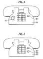
- Figure 5 shows an alternative version of telephone 202 which includes "ready enable" button 502.
- ready enable button 502 on telephone 105 will a ready signal originated from telephone 107 be transmitted to telephone 105.
- the ready signal and the ready enable signal are originated by pressing unique buttons which are in addition to those currently contained in a telephone key pad.
- these functions can be carried out using the keys of a traditional telephone key pad by assigning a specific sequence of keys to each function. For example, instead of referring to a ready enable button, the above recording could say in part, "If you wish to receive a ready signal, press STAR 21.” Similarly, instead of pressing ready button 204, the operator of telephone 107 could press a previously assigned sequence of buttons, such as # 7, to accomplish the same function.
- the system configuration can allow the recipient of a ready signal to terminate the ready signal by pressing either a unique "ready termination” button, a predetermined sequence of buttons, or any button on the key pad.
- the switch hook buttons can be used to terminate the ready signal.
- either the ready signal or the ready termination signal can be initiated through voice recognition.
- the system can issue a ready signal upon recognition of a voice signal into telephone 107.
- the system can terminate the ready signal upon recognition of a voice signal into telephone 105.
- issuance or termination of the ready signal can occur on the recognition of any voice signal
- issuance or termination of the ready signal can occur on the recognition of specific voice signals previously identified to be representative of the voices of authorized users.
- specific users would thus be identified as authorized users of each telephone.
- issuance or termination of the ready signal can occur on the recognition of specific voice signals previously identified to be associated with specific voice commands.
- the telephone users would be instructed to verbally issue appropriate commands, such as "READY" or "TERMINATE" into the telephone. The appropriate action would then occur upon recognition of the associated command.
Abstract
Description
- Modern telephone systems have many features intended to improve the efficiency of communication. For example, a business which depends upon customer-initiated telephone calls can configure a telephone system to insure that incoming callers no longer receive a busy signal when all of the incoming lines are in use. Instead of receiving a busy signal, each incoming caller will be placed in a queue to be handled in turn by the next available operator. Although such a system helps prevent lost business by substantially reducing or eliminating the receipt of a busy signal by an incoming caller, it does not solve all the problems for the business receiving the calls. In place of the traditional busy signal, an incoming caller may now experience a lengthy wait time while waiting for his or her turn in the queue.
- If the wait time is unnecessarily long, the incoming caller may choose to discontinue the call prior to completion of the wait time. As a result, the business receiving the incoming call may lose a customer. Alternatively, the incoming caller may experience an increased level of frustration while he or she waits for his or her turn in the queue, thus causing the ensuing conversation to have a tone which is less than optimal to the business receiving the call. Part of the increased frustration level is due to the fact that the incoming caller must wait, with their telephone instrument pressed to their ear, until it is that caller's turn. Thus, the incoming caller is prevented from carrying on other activities while waiting for his or her turn in the queue.
- We will describe a system and method whereby an incoming caller's wait in the queue is less frustrating to the incoming caller. As a result, the business receiving the incoming calls will experience fewer lost or frustrated customers.
- We will describe a telephone system wherein a "ready" signal is sent from the recipient of the telephone call to the initiator of the telephone call when the initiator has moved up in the queue to the point where communication can commence between the initiator and the recipient. As a result, the telephone call initiator need not remain in a position of listening to his or her telephone instrument until the recipient is ready.
- The system can provide a ready signal in either audio or video form. For example, the system can provide an alarm or a tone which is heard by the telephone call initiator as it is broadcast from his or her telephone instrument. The system may also provide a visual ready signal such as a light associated with the telephone call initiator's telephone which is illuminated when the recipient of the telephone call is ready.
- The system can allow for either automatic initiation of the ready signal by the recipient's telephone processing system or manual initiation by an operator of the recipient's telephone. Manual operation can include the pressing of a button specifically assigned to the function of issuing a ready signal (a "ready button"), or can alternatively comprise pressing a predetermined sequence of buttons contained in a conventional telephone key pad.
- Similarly, the initiator of the telephone call can have the option of setting the ready function via either a special button or a predetermined sequence of buttons contained in the conventional key pad. The telephone call initiator can also have the option of terminating the ready signal in order to begin communicating with the recipient. The system can allow for termination of the ready signal, by, for example, pressing a button specifically assigned to this function, pressing any button on the telephone key pad, pressing a predetermined sequence of buttons on the telephone key pad or pressing the switch hook of the telephone.
- These and other objects of the present invention will be apparent to one of ordinary skill upon review of the specification and figures wherein:
- Figure 1 shows a high level telephone connection topology;
- Figure 2 shows an example of a telephone in accordance with one embodiment of the invention;
- Figure 3 shows an example of a telephone in accordance with another embodiment of the invention;
- Figure 4 shows an example of a telephone in accordance with still another embodiment of the invention; and
- Figure 5 shows an example of a telephone in accordance with yet another embodiment of the invention.
- Although the primary use of the present invention is envisioned in a situation where a large number of customers are calling a business and competing for a small number of incoming telephone lines, the invention is herein described with relation to one incoming caller and one telephone call recipient for purposes of simplicity.
- Figure 1 shows
telephones switching network 109. Presume a caller initiates a telephone call fromtelephone 105 totelephone 107. To do so, acaller using telephone 105 dials the telephone number associated withtelephone 107. Switchingnetwork 109, upon receipt of the telephone number fortelephone 107, sends a ringing signal totelephone 107, causingtelephone 107 to ring. If, however,telephone 107 is already in use, the traditional result is that a busy signal is sent totelephone 105 viaswitching network 109. The caller ontelephone 105 is then forced to retry the call at a later time. - If
telephone 107 is a modern telephone system, on the other hand, in place of a busy signal,telephone 105 may receive a prerecorded statement indicating that the target telephone (telephone 107) is busy and that the call initiated bytelephone 105 will be handled in turn. As a result, thecaller using telephone 105 will stay on the line until his or her turn comes up. Alternatively, the caller ontelephone 105 can decide not to wait on the line and then choose to either retry the call at a later time or call somebody else to communicate. If the target recipient (telephone 107) is a business, the latter choice by the caller can be very costly. - The present arrangement provides an additional option which minimizes the negative impact on the caller of having to wait for his or her turn to communicate. Via the present invention, the
caller using telephone 105 can put the handset fromtelephone 105 down on a desk or table upon whichtelephone 105 is sitting and go about his or her business until receiving a ready signal fromtelephone 107. The system can provide for the ready signal in the form of one or more of a visual signal such as a light ontelephone 105 which illuminates, a ringing oftelephone 105, and an audible alarm similar to the alarm currently heard when a telephone handset is advertently left off-hook. - Figure 2 shows an example of a telephone in accordance with one embodiment of the present invention.
Telephone 202 is a conventional telephone with the addition of "ready button" 204. If a telephone such astelephone 202 is used fortelephone 107 in the example of Figure 1, the operator oftelephone 107 can pressready button 204 when preparing to handle the next call in the queue in order to provide an indicator to the associated caller that it is now that caller's turn. Most likely, the operator oftelephone 107 would first speak into the instrument and listen to hear if the calling party is still on the line. If so, the use ofready button 204 is unnecessary. If, however, the user oftelephone 107 does not hear a response to a verbal inquiry, thenready button 204 can be pressed in order to send a ready signal totelephone 105. - The ready signal may take many forms. In one form, it is exactly the same as the signal currently received when a telephone is inadvertently left off the hook. Thus, the user of
telephone 105 can merely place the instrument down on a table or desk (still off-hook) and go about his or her business until hearing the familiar off-hook tone. At this time, the initiator of the phone call can pick up the instrument and begin communicating with the operator oftelephone 107. Of course, for this communication to occur, the "off-hook" tone must be terminated. One manner of terminating the off-hook tone is to have the off-hook tone last for a predetermined short duration, such as two or three seconds. Alternatively, the caller fromtelephone 105 can press a predetermined series of buttons, such as * 5, in order to terminate the off-hook tone. Alternatively, the system can allow the caller to press any of the keys on the key pad oftelephone 105 to terminate the off-hook tone. Alternatively, the caller can press the switch hook button or buttons (those buttons which are suppressed by the hand set when the telephone is hung up) to terminate the "off-hook" tone. - Alternatively, the system can use a tone which differs from the off-hook tone as the ready signal so that the caller from
telephone 105 can distinguish between the traditional off-hook tone and the ready signal. This configuration provides a benefit since a loss of telephone connection betweentelephones telephone 105, thus providing the traditional signal thattelephone 105 is off the hook. Therefore, a tone which a user can distinguish from the traditional off-hook tone allows the caller to immediately know upon hearing the tone whether it is an indication that the other party is now on the line or an indication that the call is disconnected. - As discussed above, the ready signal in one embodiment of the present invention can take the form of an audio signal which is transmitted from the hand set of
telephone 105. If the audio signal selected is the same as the off-hook signal, then the present invention produces a second condition for generation of the off-hook signal. As discussed above, the traditional basis for generating the off-hook tone is that the telephone has been off the hook for a predetermined period of time. This can be considered "Condition 1". The present invention also provides "Condition 2" for generating the off-hook tone, which is that theperson using telephone 107 presses a button such asready button 204 while the connection is established betweentelephones network 109 must be updated to issue the signals associated with the off-hook tone upon the occurrence of eithercondition 1 or condition 2 instead of its current operational scheme wherein these signals are only sent on the occurrence ofcondition 1. - Figure 3 shows in greater detail the connection between
telephone 107 and a front end portion of switchingnetwork 109 for an exemplary implementation of one embodiment of the invention. In this configuration, the traditional off-hook tone is also used as the ready signal.Front end portion 301 of switchingnetwork 109 includes a Subscriber Line Integrated Circuit (SLIC) 303, a Dual Tone Multi-Frequency (DTMF) detector/decoder 305 and amicrocontroller 307.Telephone 107 is connected tofront end portion 301 via a twisted pair of wires called Tip and Ring. - The Tip and Ring wires carry voice signals along with DTMF tones. Voice signals comprise various inband frequencies from 300 Hz to 3 KHz, whereas DTMF tones are combinations of two pure tones of inband frequencies. The voice signals and DTMF tones are supplied to
front end portion 301 as analog signals by the Tip and Ring wires. These analog signals are digitized bySLIC 303 and fed toDTMF detector 305. - Whenever a button of the telephone keypad is pressed, the DTMF detector detects the digitized tones and decodes the digital information to identify the key that was pressed. Information identifying the key that was pressed is then passed to
microcontroller 307. Similarly, a combination of pure tones assigned toready buttdn 204 are carried in analog form over the Tip and Ring wires. The analog signal is then digitized bySLIC 303 and sent toDTMF detector 305, where the digital information corresponding to the ready button is recognized. As a result, an indicator that the ready button was pressed is sent fromDTMF detector 305 tomicrocontroller 307. -
Microcontroller 307, in response to the indicator received fromDTMF detector 305, sends a ready signal to the telephone currently communicating withtelephone 107. In the present example, the ready signal comprises the off-hook signal and the telephone communicating withtelephone 107 is telephone 105 (Figure 1). Thus,microcontroller 307 causes the issuance of an off-hook signal totelephone 105. - Thus, in this example,
microcontroller 307 causes an off-hook tone to issue to telephone 105 upon the occurrence of either condition 1 (telephone 105 off the hook and not connected to another telephone for a predetermined period of time) or condition 2 (a ready button pressed on the telephone connected to telephone 105). - In addition to, or instead of, the audio signal, the ready signal can take the form of a visual signal, such as the illumination of a light associated with
telephone 105. An example is shown in Figure 4 aslight 401. The pressing ofbutton 204 at telephone 107 (Figure 1) results in the illumination of light 401 attelephone 105. Thus, the calling party may engage in activities within visual range oftelephone 105 while waiting for his or her turn to communicate withtelephone 107, even if the environment is sufficiently noisy such that the audio alarm described above could not be heard. - It is possible that calling parties may not wish to receive a ready signal as described above. In such a case, it may be preferable to have the ready signal transmitted only upon an appropriate selection by the calling party. For example, at the time the call is received by
telephone 107, a prerecorded message could be sent totelephone 105 stating:
All our operators are busy. Please remain on the line and your call will be handled in turn. If you would like to receive a ready signal, you may press the ready enable button on your telephone. Please do not hang your phone up. If you press the ready enable button, a ready signal will be transmitted from the handset of your phone when it is your turn. - In accordance with the aforementioned embodiment, Figure 5 shows an alternative version of
telephone 202 which includes "ready enable"button 502. Thus, only if the caller has pressed ready enablebutton 502 ontelephone 105 will a ready signal originated fromtelephone 107 be transmitted totelephone 105. - As described above, the ready signal and the ready enable signal are originated by pressing unique buttons which are in addition to those currently contained in a telephone key pad. Alternatively, these functions can be carried out using the keys of a traditional telephone key pad by assigning a specific sequence of keys to each function. For example, instead of referring to a ready enable button, the above recording could say in part, "If you wish to receive a ready signal, press STAR 21." Similarly, instead of pressing
ready button 204, the operator oftelephone 107 could press a previously assigned sequence of buttons, such as # 7, to accomplish the same function. - In a similar manner, the system configuration can allow the recipient of a ready signal to terminate the ready signal by pressing either a unique "ready termination" button, a predetermined sequence of buttons, or any button on the key pad. Alternatively, since the telephone receiver is off the hook, the switch hook buttons can be used to terminate the ready signal.
- In an alternative embodiment, either the ready signal or the ready termination signal can be initiated through voice recognition. For example, the system can issue a ready signal upon recognition of a voice signal into
telephone 107. Similarly, the system can terminate the ready signal upon recognition of a voice signal intotelephone 105. - This configuration can take the form of various alternative implementations. For example, issuance or termination of the ready signal can occur on the recognition of any voice signal, Alternatively, issuance or termination of the ready signal can occur on the recognition of specific voice signals previously identified to be representative of the voices of authorized users. In this example, specific users would thus be identified as authorized users of each telephone. Alternatively, issuance or termination of the ready signal can occur on the recognition of specific voice signals previously identified to be associated with specific voice commands. In this example, the telephone users would be instructed to verbally issue appropriate commands, such as "READY" or "TERMINATE" into the telephone. The appropriate action would then occur upon recognition of the associated command.
- As described above, various methodologies are provided to ease the wait time of a telephone user. While several embodiments of the invention have been described, it will be understood that it is capable of further modifications, and this application is intended to cover any variations, uses, or adaptations of the invention, following in general the principles of the invention and including such departures from the present disclosure as to come within knowledge or customary practice in the art to which the invention pertains, and as may be applied to the essential features hereinbefore set forth and falling within the scope of the invention or the limits of the appended claims.
Claims (23)
- A telephone system comprising a switching network and a plurality of telephones connected via the switching network, each of the telephones comprising:means for initiating an outgoing call to a receiving telephone;means for receiving an incoming call from a calling telephone;means for placing the incoming call into a queue; andmeans for initiating a ready signal to be provided to the calling telephone, the ready signal informing a calling party located near the calling telephone that the incoming call is now at the front of the queue such that communication can begin between a receiving party and the calling party.
- A telephone system as recited in claim 1, wherein the ready signal is an audio signal.
- A telephone system as recited in claim 1, wherein the ready signal is a visual signal.
- A telephone system as recited in claim 2, wherein the audio signal is an off-hook signal.
- A telephone system as recited in claim 3, wherein the visual signal is provided by illuminating a light associated with the calling telephone.
- A telephone system as recited in claim 1, wherein the means for initiating a ready signal comprises a ready button associated with each telephone, such that the ready signal is initiated when the ready button is pressed.
- A telephone system as recited in claim 1, wherein the means for initiating a ready signal comprises a predetermined series of buttons on a keypad associated with each telephone, such that the ready signal is initiated when the predetermined series of buttons is pressed.
- A telephone system as recited in claim 1, wherein each telephone further comprises:means for receiving a ready signal from the receiving telephone indicating that the outgoing call is now at the front of a queue associated with the receiving telephone; andmeans for terminating the ready signal from the receiving telephone.
- A telephone system as recited in claim 8, wherein the means for terminating the ready signal comprises a ready termination button associated with each telephone, such that the ready signal is terminated when the ready termination button is pressed.
- A telephone system as recited in claim 8, wherein the means for terminating the ready signal comprises a predetermined series of buttons on a keypad associated with each telephone, such that the ready signal is terminated when the predetermined series of buttons is pressed.
- A telephone system as recited in claim 8, wherein the means for terminating the ready signal comprises a keypad associated with each telephone, such that the ready signal is terminated when any button on the keypad is pressed.
- A telephone system as recited in claim 8, wherein the means for terminating the ready signal comprises a switch-hook associated with each telephone, such that the ready signal is terminated when the switch-hook is pressed.
- A method of receiving a plurality of incoming telephone calls at a receiving telephone, comprising the steps of:placing the telephone calls in a queue based on an order of receipt associated with the telephone calls;moving the telephone calls up one place in the queue upon completing a telephone call previously contained in the first place in the queue;sending a ready signal to a calling telephone associated with a telephone call that is newly moved into the first place in the queue by the moving step; andcommunicating with the calling telephone until completing the telephone call with the calling telephone.
- A method as recited in claim 13, wherein the ready signal is sent by pressing a ready button associated with the receiving telephone.
- A method as recited in claim 13, wherein the ready signal is sent by pressing a predetermined series of buttons on a keypad associated with the receiving telephone.
- A method as recited in claim 13, further comprising the step of enabling, from the calling telephone when the telephone call is placed in the queue, the transmission of the ready signal from the receiving telephone to the calling telephone when the telephone call is newly moved into the first place in the queue.
- A method as recited in claim 16, wherein the step of enabling comprises pressing a ready enable button associated with the calling telephone in response to a query from the receiving telephone.
- A method as recited in claim 16, wherein the step of enabling comprises pressing a predetermined series of buttons on a keypad associated with the calling telephone in response to a query from the receiving telephone.
- A method as recited in claim 13, further comprising the step of terminating the ready signal at the calling telephone.
- A method as recited in claim 19, wherein the terminating step comprises pressing a ready termination button associated with the calling telephone.
- A method as recited in claim 19, wherein the terminating step comprises pressing a predetermined series of buttons on a keypad associated with the calling telephone.
- A method as recited in claim 19, wherein the terminating step comprises pressing any button on a keypad associated with the calling telephone.
- A method as recited in claim 19, wherein the terminating step comprises pressing a switch-hook associated with the calling telephone.
Applications Claiming Priority (2)
| Application Number | Priority Date | Filing Date | Title |
|---|---|---|---|
| US08/400,880 US5572587A (en) | 1995-03-08 | 1995-03-08 | Telephone system and method for easing wait time in queue |
| US400880 | 1995-03-08 |
Publications (2)
| Publication Number | Publication Date |
|---|---|
| EP0736994A2 true EP0736994A2 (en) | 1996-10-09 |
| EP0736994A3 EP0736994A3 (en) | 1999-10-27 |
Family
ID=23585385
Family Applications (1)
| Application Number | Title | Priority Date | Filing Date |
|---|---|---|---|
| EP96301592A Withdrawn EP0736994A3 (en) | 1995-03-08 | 1996-03-08 | Telephone system |
Country Status (4)
| Country | Link |
|---|---|
| US (1) | US5572587A (en) |
| EP (1) | EP0736994A3 (en) |
| JP (1) | JPH08321881A (en) |
| KR (1) | KR960036495A (en) |
Cited By (2)
| Publication number | Priority date | Publication date | Assignee | Title |
|---|---|---|---|---|
| WO2001013665A1 (en) * | 1999-08-12 | 2001-02-22 | Nokia Corporation | Method for handling a call |
| GB2409605A (en) * | 2003-12-23 | 2005-06-29 | Nec Technologies | Notification at calling terminal of called party answering call |
Families Citing this family (10)
| Publication number | Priority date | Publication date | Assignee | Title |
|---|---|---|---|---|
| US5764746A (en) * | 1996-05-30 | 1998-06-09 | Ericsson, Inc. | Holding party call back subscriber feature |
| US6031905A (en) * | 1997-09-17 | 2000-02-29 | At&T Corp | Network-based call hold stand by |
| US6141328A (en) * | 1997-09-29 | 2000-10-31 | Qwest Communications International Inc. | Method and system for two-way negotiated call hold |
| US6853725B2 (en) * | 2001-03-22 | 2005-02-08 | Hubbell Incorporated | Method and apparatus for off-hook management of plural subscriber premises devices connected to same telephone line |
| GB0111757D0 (en) * | 2001-05-14 | 2001-07-04 | Nokia Corp | Handling queued sessions |
| US6959081B2 (en) * | 2001-12-03 | 2005-10-25 | International Business Machines Corporation | Expert hold queue management |
| US7139390B2 (en) * | 2001-12-12 | 2006-11-21 | International Business Machines Corporation | Promoting use of experts to callers waiting in a hold queue |
| US6956935B2 (en) * | 2001-12-17 | 2005-10-18 | International Business Machines Corporation | Origin device billing according to caller |
| US6977998B2 (en) * | 2001-12-17 | 2005-12-20 | International Business Machines Corporation | Destination device billing according to call recipient |
| US8532269B2 (en) * | 2009-01-16 | 2013-09-10 | Microsoft Corporation | In-band signaling in interactive communications |
Citations (2)
| Publication number | Priority date | Publication date | Assignee | Title |
|---|---|---|---|---|
| EP0222251A2 (en) * | 1985-11-04 | 1987-05-20 | AT&T Corp. | A method of providing notification to a held party. |
| US4788715A (en) * | 1986-10-16 | 1988-11-29 | American Telephone And Telegraph Company At&T Bell Laboratories | Announcing waiting times in queuing systems |
Family Cites Families (15)
| Publication number | Priority date | Publication date | Assignee | Title |
|---|---|---|---|---|
| US3865985A (en) * | 1973-09-07 | 1975-02-11 | Letot Inc | Telephone control system having wakeup, message waiting, special message and fire alert modes |
| US4669110A (en) * | 1985-10-25 | 1987-05-26 | Itt Corporation | Call progress tone system |
| US4775975A (en) * | 1985-11-26 | 1988-10-04 | American Telephone And Telegraph Company And At&T Information Systems Inc. | Dial tone detection arrangement with a detection notification feature |
| KR910003923B1 (en) * | 1988-06-30 | 1991-06-15 | 삼성전자 주식회사 | Method transmitting automatic arrangement and out-in ring to a person who in on the line |
| US5233641A (en) * | 1989-03-08 | 1993-08-03 | Nec Corporation | Radio telephone equipment having a sounding device for generating alert tone indicative of response of called subscriber |
| US5034975A (en) * | 1989-12-21 | 1991-07-23 | At&T Bell Laboratories | Voice announcement device for improving functionality of multi-line telephones |
| US5155761A (en) * | 1990-01-26 | 1992-10-13 | Intervoice, Inc. | Automatic call back system and method of operation |
| US5172408A (en) * | 1990-08-01 | 1992-12-15 | At&T Bell Laboratories | Speakerphone state-controlled alerting arrangement |
| US5181236A (en) * | 1990-09-25 | 1993-01-19 | Rockwell International Corporation | Automatic call returning method for call distributor with message record capability |
| US5265157A (en) * | 1990-10-16 | 1993-11-23 | International Business Machines Corporation | Answer supervision and service selection |
| US5134651A (en) * | 1991-04-18 | 1992-07-28 | Codecom Rural Communications, Inc. | Method and apparatus for providing answer supervision and an autonomous pay telephone incorporating the same |
| JPH05300246A (en) * | 1991-06-12 | 1993-11-12 | Nec Corp | Automatic transmission system for busy state message in telephone communication |
| US5329578A (en) * | 1992-05-26 | 1994-07-12 | Northern Telecom Limited | Personal communication service with mobility manager |
| US5388150A (en) * | 1992-07-28 | 1995-02-07 | Schneyer; Robin | Automatic incoming telephone call identification and disposition system |
| US5327486A (en) * | 1993-03-22 | 1994-07-05 | Bell Communications Research, Inc. | Method and system for managing telecommunications such as telephone calls |
-
1995
- 1995-03-08 US US08/400,880 patent/US5572587A/en not_active Expired - Lifetime
-
1996
- 1996-03-08 KR KR1019960006077A patent/KR960036495A/en not_active Application Discontinuation
- 1996-03-08 EP EP96301592A patent/EP0736994A3/en not_active Withdrawn
- 1996-03-08 JP JP8051858A patent/JPH08321881A/en not_active Withdrawn
Patent Citations (2)
| Publication number | Priority date | Publication date | Assignee | Title |
|---|---|---|---|---|
| EP0222251A2 (en) * | 1985-11-04 | 1987-05-20 | AT&T Corp. | A method of providing notification to a held party. |
| US4788715A (en) * | 1986-10-16 | 1988-11-29 | American Telephone And Telegraph Company At&T Bell Laboratories | Announcing waiting times in queuing systems |
Non-Patent Citations (1)
| Title |
|---|
| M.ZWEEDIJK: "Beurtmelders" DATA, vol. 70, no. 3, October 1969 (1969-10), pages 61-66, XP002113279 NL * |
Cited By (3)
| Publication number | Priority date | Publication date | Assignee | Title |
|---|---|---|---|---|
| WO2001013665A1 (en) * | 1999-08-12 | 2001-02-22 | Nokia Corporation | Method for handling a call |
| US6983145B1 (en) | 1999-08-12 | 2006-01-03 | Nokia Corporation | Method for handling a call when destined subscriber is unable to answer |
| GB2409605A (en) * | 2003-12-23 | 2005-06-29 | Nec Technologies | Notification at calling terminal of called party answering call |
Also Published As
| Publication number | Publication date |
|---|---|
| EP0736994A3 (en) | 1999-10-27 |
| JPH08321881A (en) | 1996-12-03 |
| KR960036495A (en) | 1996-10-28 |
| US5572587A (en) | 1996-11-05 |
Similar Documents
| Publication | Publication Date | Title |
|---|---|---|
| US4850012A (en) | Automated access facilities for use with key telephone systems | |
| US6337898B1 (en) | Method for monitoring voicemail calls using ADSI capable CPE | |
| US4922526A (en) | Automated access facilities for use with key telephone systems | |
| EP1038384B1 (en) | System and method of responding to an incoming call while conferencing | |
| US5836009A (en) | Caller ID telephone with signal attenuation | |
| WO1999026394A1 (en) | System and method for self-announcing a caller of an incoming telephone call | |
| US5572587A (en) | Telephone system and method for easing wait time in queue | |
| JPH10308825A (en) | Enhanced voice mail system and method using it | |
| EP0541087A1 (en) | Facsimile receiving method and facsimile apparatus carrying out the method | |
| EP0109431A1 (en) | Combined handset and headset arrangement. | |
| US5878118A (en) | Computerized telephone apparatus | |
| US6597766B1 (en) | Telephone apparatus | |
| US7231207B1 (en) | Intelligent incoming call management during cordless intercom mode | |
| US7957515B1 (en) | Selective telephone blocker with timer | |
| JPH0715490A (en) | Telephone set compatible with catchphone function | |
| WO2002013496A2 (en) | Method and apparatus for programmed call back | |
| EP1128645B1 (en) | Intelligent incoming call management during cordless intercom mode | |
| KR100396048B1 (en) | Apparatus for dialing automatically | |
| KR200240708Y1 (en) | Transmission of the sound of a language for one-button dialing system | |
| US20040151286A1 (en) | Self-contained single telephone line voice and internet device with DTMF generation capability | |
| GB2342809A (en) | Method for monitoring voicemail calls using ADSI capable CPE | |
| KR19980073680A (en) | Apparatus and method for selecting music on hold of telephone | |
| JPH0254658A (en) | Multi-functional telephone set | |
| JPH07112211B2 (en) | Digital telephone with audible sound transmission function | |
| JPS63256039A (en) | Caller identification device |
Legal Events
| Date | Code | Title | Description |
|---|---|---|---|
| PUAI | Public reference made under article 153(3) epc to a published international application that has entered the european phase |
Free format text: ORIGINAL CODE: 0009012 |
|
| AK | Designated contracting states |
Kind code of ref document: A2 Designated state(s): AT BE DE DK ES FI FR GB GR IE IT LU NL PT SE |
|
| PUAL | Search report despatched |
Free format text: ORIGINAL CODE: 0009013 |
|
| AK | Designated contracting states |
Kind code of ref document: A3 Designated state(s): AT BE DE DK ES FI FR GB GR IE IT LU NL PT SE |
|
| 17P | Request for examination filed |
Effective date: 20000207 |
|
| STAA | Information on the status of an ep patent application or granted ep patent |
Free format text: STATUS: THE APPLICATION IS DEEMED TO BE WITHDRAWN |
|
| 18D | Application deemed to be withdrawn |
Effective date: 20020910 |