EP0738199B1 - Method for planning/controlling robot motion - Google Patents
Method for planning/controlling robot motion Download PDFInfo
- Publication number
- EP0738199B1 EP0738199B1 EP95936761A EP95936761A EP0738199B1 EP 0738199 B1 EP0738199 B1 EP 0738199B1 EP 95936761 A EP95936761 A EP 95936761A EP 95936761 A EP95936761 A EP 95936761A EP 0738199 B1 EP0738199 B1 EP 0738199B1
- Authority
- EP
- European Patent Office
- Prior art keywords
- robot
- movements
- movement
- workpiece
- motion
- Prior art date
- Legal status (The legal status is an assumption and is not a legal conclusion. Google has not performed a legal analysis and makes no representation as to the accuracy of the status listed.)
- Expired - Lifetime
Links
Images


Classifications
-
- B—PERFORMING OPERATIONS; TRANSPORTING
- B25—HAND TOOLS; PORTABLE POWER-DRIVEN TOOLS; MANIPULATORS
- B25J—MANIPULATORS; CHAMBERS PROVIDED WITH MANIPULATION DEVICES
- B25J9/00—Programme-controlled manipulators
- B25J9/16—Programme controls
- B25J9/1656—Programme controls characterised by programming, planning systems for manipulators
- B25J9/1664—Programme controls characterised by programming, planning systems for manipulators characterised by motion, path, trajectory planning
- B25J9/1666—Avoiding collision or forbidden zones
-
- G—PHYSICS
- G05—CONTROLLING; REGULATING
- G05B—CONTROL OR REGULATING SYSTEMS IN GENERAL; FUNCTIONAL ELEMENTS OF SUCH SYSTEMS; MONITORING OR TESTING ARRANGEMENTS FOR SUCH SYSTEMS OR ELEMENTS
- G05B2219/00—Program-control systems
- G05B2219/30—Nc systems
- G05B2219/40—Robotics, robotics mapping to robotics vision
- G05B2219/40421—Motion planning for manipulator handling sheet metal profiles
-
- G—PHYSICS
- G05—CONTROLLING; REGULATING
- G05B—CONTROL OR REGULATING SYSTEMS IN GENERAL; FUNCTIONAL ELEMENTS OF SUCH SYSTEMS; MONITORING OR TESTING ARRANGEMENTS FOR SUCH SYSTEMS OR ELEMENTS
- G05B2219/00—Program-control systems
- G05B2219/30—Nc systems
- G05B2219/40—Robotics, robotics mapping to robotics vision
- G05B2219/40444—Hierarchical planning, in levels
-
- G—PHYSICS
- G05—CONTROLLING; REGULATING
- G05B—CONTROL OR REGULATING SYSTEMS IN GENERAL; FUNCTIONAL ELEMENTS OF SUCH SYSTEMS; MONITORING OR TESTING ARRANGEMENTS FOR SUCH SYSTEMS OR ELEMENTS
- G05B2219/00—Program-control systems
- G05B2219/30—Nc systems
- G05B2219/40—Robotics, robotics mapping to robotics vision
- G05B2219/40445—Decompose n-dimension with n-links into smaller m-dimension with m-1-links
-
- G—PHYSICS
- G05—CONTROLLING; REGULATING
- G05B—CONTROL OR REGULATING SYSTEMS IN GENERAL; FUNCTIONAL ELEMENTS OF SUCH SYSTEMS; MONITORING OR TESTING ARRANGEMENTS FOR SUCH SYSTEMS OR ELEMENTS
- G05B2219/00—Program-control systems
- G05B2219/30—Nc systems
- G05B2219/40—Robotics, robotics mapping to robotics vision
- G05B2219/40446—Graph based
-
- G—PHYSICS
- G05—CONTROLLING; REGULATING
- G05B—CONTROL OR REGULATING SYSTEMS IN GENERAL; FUNCTIONAL ELEMENTS OF SUCH SYSTEMS; MONITORING OR TESTING ARRANGEMENTS FOR SUCH SYSTEMS OR ELEMENTS
- G05B2219/00—Program-control systems
- G05B2219/30—Nc systems
- G05B2219/40—Robotics, robotics mapping to robotics vision
- G05B2219/40458—Grid adaptive optimization
-
- G—PHYSICS
- G05—CONTROLLING; REGULATING
- G05B—CONTROL OR REGULATING SYSTEMS IN GENERAL; FUNCTIONAL ELEMENTS OF SUCH SYSTEMS; MONITORING OR TESTING ARRANGEMENTS FOR SUCH SYSTEMS OR ELEMENTS
- G05B2219/00—Program-control systems
- G05B2219/30—Nc systems
- G05B2219/40—Robotics, robotics mapping to robotics vision
- G05B2219/40463—Shortest distance in time, or metric, time optimal
-
- G—PHYSICS
- G05—CONTROLLING; REGULATING
- G05B—CONTROL OR REGULATING SYSTEMS IN GENERAL; FUNCTIONAL ELEMENTS OF SUCH SYSTEMS; MONITORING OR TESTING ARRANGEMENTS FOR SUCH SYSTEMS OR ELEMENTS
- G05B2219/00—Program-control systems
- G05B2219/30—Nc systems
- G05B2219/40—Robotics, robotics mapping to robotics vision
- G05B2219/40476—Collision, planning for collision free path
-
- G—PHYSICS
- G05—CONTROLLING; REGULATING
- G05B—CONTROL OR REGULATING SYSTEMS IN GENERAL; FUNCTIONAL ELEMENTS OF SUCH SYSTEMS; MONITORING OR TESTING ARRANGEMENTS FOR SUCH SYSTEMS OR ELEMENTS
- G05B2219/00—Program-control systems
- G05B2219/30—Nc systems
- G05B2219/40—Robotics, robotics mapping to robotics vision
- G05B2219/40488—Coarse and fine motion planning combined
-
- G—PHYSICS
- G05—CONTROLLING; REGULATING
- G05B—CONTROL OR REGULATING SYSTEMS IN GENERAL; FUNCTIONAL ELEMENTS OF SUCH SYSTEMS; MONITORING OR TESTING ARRANGEMENTS FOR SUCH SYSTEMS OR ELEMENTS
- G05B2219/00—Program-control systems
- G05B2219/30—Nc systems
- G05B2219/40—Robotics, robotics mapping to robotics vision
- G05B2219/40497—Collision monitor controls planner in real time to replan if collision
-
- G—PHYSICS
- G05—CONTROLLING; REGULATING
- G05B—CONTROL OR REGULATING SYSTEMS IN GENERAL; FUNCTIONAL ELEMENTS OF SUCH SYSTEMS; MONITORING OR TESTING ARRANGEMENTS FOR SUCH SYSTEMS OR ELEMENTS
- G05B2219/00—Program-control systems
- G05B2219/30—Nc systems
- G05B2219/45—Nc applications
- G05B2219/45143—Press-brake, bending machine
Definitions
- the invention relates to a method and a system for planning the motion of a robot according to the preamble part of claims 1 and 24, respectively.
- the described planner creates a route plan in two levels of hierarchy.
- the first level selects doors to pass through minimizing the total number of doors.
- the second level generates a near shortest trajectory inside a room.
- heuristic pruning strategies are employed in a path search procedure.
- the planner uses a two dimensional environment map. Obstacles in the environment map are enlarged by the size of the robot, to permit the point robot assumption.
- a costs function is used by the planner involving the total path length from the initial node to the present position, the straight-line distance from the present position to the goal node and a heuristic cost function eliminating meaningless backtracking.
- the resulting rectangloid decomposition is utilized to search for a solution path connecting a start position Q init to a goal position Q goal .
- An algorithm that may be utilized to find the solution path is as follows:
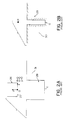
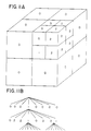
- a divide-and-label method may be performed, as illustrated in Fig. 1.
- the method comprises the steps of first dividing a cell into smaller cells, as illustrated in Fig. 1, and then labeling each newly created cell according to whether it intersects a C-obstacle region.
- a widely used technique for decomposing a rectangloid ⁇ into smaller rectangloids is to compute a 2 m -tree decomposition.
- a tree is formed having nodes, each of which represents a rectangloid cell which is labeled as either EMPTY, FULL or MIXED.
- the root node of the tree is ⁇ .
- Each node which represents a MIXED cell will then be decomposed to form 2 m children nodes.
- Fig. 1 shows an octree decomposition of a parallelepiped representation 10 of a portion of configuration space, and displays a portion of an octree graph 12.
- the overall height h of the tree i.e., the depth of the deepest node determines the resolution of the decomposition, and hence the size of the smallest cells in the decomposition.
- a maximum height h max of the tree may be specified to thereby limit the iterative process carried out by steps 2 and 3 of the algorithm noted above.
- octree graph 12 does not correspond precisely to the parallelepiped 10 depicted in Fig. 1. Rather, the various rectangloids depicted in octree graph 12 are chosen randomly in order to simplify the illustration.
- the above described approximate cell decomposition method utilizes a configuration space approach to spatial planning, whereby the position and orientation of an object A in relation to obstacles B is characterized as a single point in a configuration space, in which the coordinates of the point represent a degree of freedom of the object in relation to the obstacles.
- the configurations i.e., the placements
- C-obstacles regions in the configuration space.
- Much literature has been published concerning the use of a configuration-space representations of an object with respect to obstacles, including a paper by Tomas Lozano-Perez, entitled “Spatial Planning: A Configuration Space Approach", IEEE Transactions on Computers, Vol. C-32, No. 2 (February 1983), the content of which is expressly incorporated by reference herein in its entirety. This paper presents several algorithms for computing configuration space obstacles formed by objects which are polygons or polyhedra.
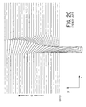
- Fig. 2A illustrates a two-dimensional representation of a peg 26 and a hole 28, wherein the goal is to place peg 26 within hole 28, so that a bottom surface 27 of peg 26 makes flush contact with a bottom surface g of hole 28.
- the position and orientation of peg 26 may be represented in two-dimensional euclidian space as a set of cartesian coordinates (x,y, ⁇ ), the origin of which is positioned at the center of bottom surface 27 of peg 26.
- Fig. 2B illustrates a configuration space representation of the real-space problem of Fig. 2A.
- a point P is shown in its initial position (as shown in Fig. 2B) and may be moved to any position along a portion G of C-surface 29.
- C-surface 29 represents a C-obstacle 30 that corresponds to an obstacle (hole) 31 represented in real-space in Fig. 2A, and point P represents peg 26.
- the position of P determines the position of peg 26 in relation to hole 28.
- the boundary of the shaded area shown in Fig. 2B represents the positions at which peg 26 would be in contact with obstacle 31, if point P was along the boundary.
- the transformation from Fig. 2A to Fig. 2B amounts to shrinking the peg 26 to a point P, and expanding obstacle 31 to form a C-obstacle 30.
- the transformation from Fig. 2A to Fig. 2B is a limited example of how one may reformulate a problem of moving a rigid object among other rigid objects as an equivalent problem of moving a point among transformed objects in a higher-dimensional space called the configuration space (C-space).
- Fig. 2B corresponds to the points at -which peg 26 will collide with obstacle 31, if the axes (x,y) of peg 26 and hole 28 are constrained to be parallel, thereby keeping 6 equal to 0.
- Fig. 2C illustrates how the C-surface changes as the orientation of peg 26, with respect to hole 28, changes, i.e., as ⁇ increases from 0 by rotating the orientation of peg 26 in a counter-clockwise direction.
- Fig. 2C thus shows in a three-dimensional C-space (x,y, ⁇ ) the configurations of peg 26 with respect to hole 28. In this space, hole 28 is defined as a C-obstacle.
- the lines illustrated in Fig. 2C represent surfaces at which some surface of peg 26 is just touching a surface of hole 28.
- Another approach to motion planning may be utilized by which the configuration is discretized into a fine regular grid of configurations, and is then searched for a free path from an initial position Q init to a goal location Q goal .
- searching the grid for a free path several types of heuristics have been proposed. Latombe notes in "Robot Motion Planning" (1991) that the most successful types of heuristics, for searching a fine regular grid of configurations for a free path, include the use of functions that are interpreted as "potential fields".
- the functions are called "potential fields" because the robot is represented as a point in configuration space which can be viewed as a particle moving under the influence of an artificial potential produced by the goal configuration (i.e., the point within the configuration space at which the point representing the robot will be at the goal) and the C-obstacles.
- the goal configuration generates an "attractive potential” which pulls the robot toward the goal
- the C-obstacles produce a "repulsive potential” which pushes the robot away from them.
- the direction of the resulting force is considered to be the most promising direction of motion.
- EP 0 335 314 A2 discloses a method and an apparatus of free space enumeration for motion planning.
- the method and the apparatus have general applicability and reduce the amount of information and calculation necessary.
- An appropriate configuration space is set up, and an appropriate strategy for free space enumeration is adopted.
- the method may include the steps of selecting cells only between the initial point and the final point.
- the configuration space may be divided into a plurality of cells defined in terms of intervals in the degrees of freedom. A collision free path in the free space joining the initial point and the final point without collision is determined.
- Bending Apparatus/Bending Workstation - a workstation or apparatus for performing modern sheet metal working functions, including bend operations.
- Bending Sheets of Malleable Material working of sheets of malleable material, such as sheet metal, including, but not limited to, up-action air bending, V bending, R bending, hemming, seaming, coining, bottoming, forming, wiping, folding type bending, custom bending and so on.
- m-Tree Representation of a Work Space a decomposition of a rectangloid representative of a work space into smaller rectangloids, such decomposition being utilized to represent which portions of the work space rectangloid are empty, full, or mixed.
- the resulting decomposition being defined in terms of a tree.
- Rectangloid - a rectangle in a two-dimensional space, or a parallelepiped in a three-dimensional space.
- the method may further include fine motion planning for planning a plurality of free-space fine motion solution paths that extend between a plurality of respective pairs of positions, q i and q g .
- the method may also comprise gross motion planning for planning a plurality of free-space gross motion solution paths that extend between a plurality of respective pairs of positions, Q i and Q g .
- the fine motion planning may comprise performing the above-noted steps of proposing, modeling, determining and generating, for each pair of positions, q i and q g .
- the proposing step may comprise specifying a plurality of movements in C-space for-the mth movement and identifying which ones of the specified plurality of movements are feasible by performing collision checking.
- the gross motion planning may comprise performing the steps of proposing, modeling, determining and generating for each pair of positions, Q i and Q g .
- the proposing step may comprise proposing a set of movements within a maximal overlapping parallelepiped within the free space of the robot.
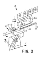
- Fig. 3 illustrates a portion of a press brake 14 of a sheet metal bending work station and a robotic manipulator (robot) 16.
- press brake 14 includes several components, such as a die rail 18, at least one die 22, at least one punch tool 20, and a backaging mechanism 24.
- a piece of sheet metal (i.e., a sheet metal workpiece) 17 is manipulated by robot 16 and placed in the die space formed between punch tool 20 and die 22, and die rail 18 is driven upward to cause punch tool 20 and die 22 to concurrently engage the sheet metal workpiece. This causes sheet metal workpiece 17 to bend in conformance with the respective complementary operating surfaces of punch tool 20 and die 22.
- Robot 16 and press brake 14, as illustrated in Fig. 3, provide a basis with which to describe a system for planning robot motion and a system for controlling robot motion, by showing an exemplary environment within which such systems may be utilized.
- the robot planning and control systems of the present invention may be utilized with an intelligent system for generating and executing a sheet metal bending plan.
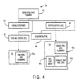
- Fig. 4 illustrates a partial block diagram of a planning/control system for generating a bending plan and for controlling operation of a sheet metal bending work station in accordance with the generated plan.
- the planning/control system includes a bend sequence planner 40, several modules/experts 42, a tooling expert 43, a motion expert 44, and a sequencer/contoller 46.
- Planner 40 operates in cooperation with each of modules/experts 42, along with tooling expert 43 and motion expert 44, to produce a plan for the complete part production of a bent sheet metal workpiece to be executed by a bending work station 14 such as that shown in Fig. 3.
- Bend sequence planner 40 generates a final plan (which includes a general list of steps and accompanying information needed to control the operation of various hardware elements of the system) and forwards the generated plan to sequencer/controller 46.
- bend sequence planner 40 participates in a dialogue with each of modules/experts 42, tooling expert 43, and motion expert 44.
- Bend sequence planner 40 queries each expert for subplan and cost information which will assist planner 40 in making decisions as to which bends and operations should make up the final generated plan which will be forwarded to sequencer/controller 46.
- Bend sequence planner 40 queries tooling expert 43 for information such as the stage that would be utilized to perform a particular bend in a bend sequence and the location on the stage at which the workpiece should be loaded in order to perform the bend.
- planner 40 queries tooling expert 43 for information including estimated k and h costs, and fine motion planning information.
- Tooling expert 43 then responds to the planner's queries with the k and h costs and various subplan information.
- the fine motion planning module is provided (in the illustrated embodiment) in tooling expert 43 since fine motion planning depends upon the type of tooling that will be utilized in performing the bends of the bend sequence.
- the motion planning system of the present invention as implemented in the embodiment illustrated in Fig. 4, generates two separate plans: a gross motion plan for navigating the robot (and other parts of the system) in free space, and a fine motion plan for navigating the robot (and workpiece which is being held by the robot) when there is contact or potential contact between one or more components of the bending workstation (usually a punch tool and die) and robot 16 or workpiece 17.
- Bend sequence planner 40 queries motion expert 44 for information including the k and h costs associated with a particular bend in a sequence of bends being generated by the bend sequence planner.
- bend sequence planner 40 queries motion expert 44 for information concerning the gross motion plan, which involves navigating the robot from one point within the overall work space of the bending apparatus to another, e.g., from a loading position of the bending apparatus to a position ready for loading into the die space at a first tooling stage of the bending apparatus.
- Bend sequence planner 40 instructs motion expert 44 to perform, among other functions, a fine motion integration function which includes integrating the gross motion plans with the fine motion plans that were generated by tooling expert 43.
- Tooling expert 43 includes a plurality of modules for performing its functions, including, e.g., fine motion planning module 43a which is shown in the box pointed to by the dotted arrow.
- Motion expert 44 includes a plurality of modules, including several modules for performing motion planning. For example, motion expert 44 includes gross motion planning module 44a, a finalize fine motion module 44b, and a motion cost assignment module 44c.
- Motion cost assignment module 44c is utilized primarily to generate the appropriate k and h costs which can be utilized by bend sequence planner 40 to decide whether or not one or more particular bend-related operations will be utilized at a particular operation within a sequence of operations being generated.
- Fig. 5 is a flow chart which illustrates a general process of performing a bend with a sheet metal bending workstation/bending apparatus such as the one illustrated in Fig. 3 herein.
- the robot 16 places a part/workpiece 17 into the die space.
- the part is aligned in several directions, including an X direction, a Y direction and a rotation (yaw) direction.
- the press table is raised until it reaches the pinch point (a point at which the die braces the workpiece against the tooling punch).
- the bend is executed with bend following (i.e., with the robot maintaining its firm hold on the workpiece throughout execution of the bend).
- the press brake is opened.
- the part is unloaded from the bending apparatus, by removing the part from the die space.
- Fig. 6 provides an illustration of several starting positions Q i and goal positions Q g through which a workpiece 17, being held by a robot gripper 19, may be moved throughout execution of a bending sequence.
- the illustrated starting positions Q i and goal positions Q g form starting and goal position pairs that form a gross motion path which is to be generated by the illustrated gross motion planner.
- the bend sequence may include various bends to be performed on several stages, including the illustrated stages, which include stage 1, stage 2, and stage 3, each of which is placed along a die rail 18.
- Each of the starting and finishing positions Q i and Q g are starting and finishing positions for which solutions will be generated by gross motion planner 44a provided within motion expert 44 of the embodiment illustrated in Fig. 4.
- robot 16 (not shown in Fig. 6) will retrieve workpiece 17 from an initial position Q i (1) from the loader/unloader (not shown) of the bending apparatus.
- the initial starting position from which the motion planner e.g., gross motion planning module 44a
- the motion planner will plan a (gross motion) solution path extending to stage 1, at position Q g (1).
- final motion planning will be utilized to plan the motion of workpiece 17 which will be used to load the workpiece into the die space, i.e., the space between the punch tool and die so that a bend may be performed.
- fine motion planning module 42a will determine a solution path for unloading the workpiece, thus returning the workpiece to position Q i (2). This is the starting position for the next gross motion plan to be generated, which will extend from stage 1 at position Q i (2) to stage 2 at Q g (2).
- a fine motion plan (which was generated by fine motion planning module 43a and integrated into the final overall motion plan) will be performed to generate a solution path for loading and unloading the workpiece into and out of the die space, the resulting position of workpiece 17 then corresponding to Q i (3) which is the starting point for a next portion of the overall plan (which is formed by a gross motion plan generated by gross motion planning module 43a), which is generated to take the robot and the workpiece from stage 2 to stage 3 at position Q g (3).
- a fine motion plan which has been integrated into the overall plan, then is executed at this point in order to load and unload the workpiece into the die space at stage 3.
- the final portion of the overall integrated motion plan which corresponds to the last gross motion plan that was generated, will extend from Q i (4) at stage 3 to the end position Q g (4), which corresponds to the position at which the workpiece is ready for retrieval by the loader/unloader (not shown).
- Fig. 7 is a flow chart of the steps within the bending process incident or relevant to fine motion planning.
- step S90 it is loaded into the die space at a particular stage location.
- step S92 the bend is performed, with bend following.
- step S94 after the bend is completed, the workpiece is unloaded from the die space, and then is ready for movement to the next stage location for a next bend, or for unloading from the bending apparatus with the use of a loader/unloader (not shown).
- fine motion planning may be performed to plan the movement of the workpiece during either or both of loading the workpiece into the die space and unloading the workpiece into the die space.
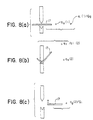
- Fig. 8 shows a plurality of side views of a workpiece 17 at different parts of a bend.
- View (a) shows workpiece 17 loaded into the die space.
- View (b) shows bend-following during the bend, corresponding to step S92 of the flow chart of Fig. 7.
- View (c) in Fig. 8 illustrates workpiece 17 as it is being unloaded from the die space, and corresponds to step S94 of the flow chart of Fig. 7.
- Fig. 8 illustrates the various fine motion plan portions of the overall integrated motion plan that would be utilized by sequencer/controller 46 to control movements of the workpiece throughout performance of several operations of the bending apparatus.
- workpiece 17 Before the workpiece is loaded into the die space, workpiece 17 is located at an initial position q i (1) which coincides with a final gross motion plan position Q g .
- a fine motion plan will be generated in order to generate a path taking the workpiece from the initial position q i (1) to a goal position q g (1) which is a loaded position of workpiece 17.
- the position q g (1) corresponds to an initial position of the workpiece before performance of a bend with bend-following.
- Bend following is then performed which results in moving the position of workpiece 17 (and also the position of the robot gripper which is holding the workpiece) to a position q f .
- the position q f corresponds to an initial position q i (2) from which a fine motion plan will be generated to take the workpiece to a final position q g (2) which corresponds to an unloaded state (unloaded from the die space).
- a plan which is generated by a gross motion planner will be utilized in the manner as shown in Fig. 6, e.g., to take workpiece 17 from a position Q i (2) at stage 1 to a position at stage 2.
- Fig. 9 is a flow chart which illustrates the general steps performed in the gross motion planning method illustrated.
- a quadtree or octree representation is formed of a rectangloid (rectangle in 2D Euclidian space or parallelepiped in 3D Euclidian space) that surrounds the overall work space in which robot 16 (Fig. 3) will be moving.
- step S62 all overlapping maximal rectangloids in free space are computed and called channels.
- step S64 a state-space search algorithm is utilized in order to generate a sequence of movements to be made by robot 16 that will bring the robot safely through the channels from a starting position Q i to a goal position Q g .
- steps S60 and S62 of the general gross motion planning method illustrated in Fig. 9 may be performed as a preliminary step off-line (i.e., apart from the computer system used to run the bending planning/control system such as that shown in Fig. 4) to create a "channel file" that defines all of the computed overlapping maximal rectangloids, the channel file then being utilized by motion expert 44 of planning/control system 38.
- Such off-line calculations may include three main modeling steps as illustrated in Fig. 10.
- a three-dimensional Euclidian model 72 of the bending press environment is prepared, where the model is bound by a parallelepiped 73 surrounding the bending press environment.
- an octree representation 74 of three-dimensional Euclidian model 72 may be computed.
- overlapping channels 76 are computed.
- the bending press and its environments may be modeled utilizing an appropriate geometric modeler, such as, e.g., the NOODLES modeling system, developed at Carnegie Mellon University, Pittsburgh, Pennsylvania.
- the bending press and its environment may be modeled by modeling the bending press and its hardware components as being solids, while modeling the surrounding free space as free space.
- the octree representation 74 illustrated in Fig. 10 may then be formed from the resulting solid representation of the free space surrounding the bend press, and the maximal overlapping channels 76 may then be determined considering the solid cells in the octree representation.
- Each channel may be written out into a channel file and may be represented by a set of coordinates (e.g., world Cartesian coordinates) representing a pair of opposite corners of each channel. For example, both a lower left front corner and a top right back corner of each channel may be described in Cartesian coordinates in order to represent the bounds of each channel that was computed.
- the resulting "channel file" may then be read by motion expert 44 when it receives an initialization instruction from bend sequence planner 70.
- octree representation 74 may comprise an octree binary refinement in three dimensional euclidian space of the space surrounding the bending press environment.
- Each parallelepiped volume element which is partially filled (i.e., mixed) is further broken down into eight elements and marked appropriately (i.e., as full, mixed, or empty) until a maximum resolution has been reached.
- the volume elements may be marked with a binary representation of "0" for empty parallelepipeds, "1" for partially filled parallelepipeds, and "2" for completely filled parallelepipeds.
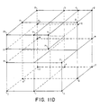
- Figs. 11C and 11D are provided to illustrate the relationship between an octree decomposition and the maximal overlapping channels that correspond to the free space cells of the composition.
- Fig. 11C shows each of the free space cells of the octree representation shown in Fig. 11A.
- a total of 9 free space cells AA, BB, CC, ... II are illustrated in the resulting representation in Fig. 11C.
- Fig. 11D is a graphic representation of the maximal overlapping parallelepipeds that correspond to the free space cells illustrated in Fig. 11C.
- a first maximal overlapping parallelepiped represented by the eight vertices (a, d, f, t, n, p, g, s) is formed by the four free space cells (AA, BB, CC, and GG).
- a second maximal overlapping parallelepiped includes vertices (m, a, t, j, u, b, r, i), and is formed by free space cells FF, AA, GG, and EE.
- a third maximal overlapping parallelepiped is represented by vertices (j, t, f, h, k, w, e, y), and is formed by free space cells EE, GG, CC, and DD.
- a fourth maximal overlapping parallelepiped may be represented by vertices (l, o, q, x, m, a, c, v), and is formed by a portion of free space cells FF, AA, and BB, along with complete free space cells II and HH.
- Each of the maximal overlapping parallelepipeds are deemed free space channels, and will be used to calculate a solution path through the channels from a start position Q init to a goal position Q goal .
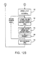
- Fig. 12A illustrates an example of a main algorithm which may be performed by gross motion planning module 44a which is provided in motion expert 44 of the planning/control system 38 illustrated in Fig. 11C.
- a first step S20 the process initiates an A* algorithm, by placing a node n 0 on an OPEN list, and setting an f value equal to 0. Then, in step S22, a determination is made as to whether or not the OPEN list is empty. If the OPEN list is empty, the process proceeds to step S24, at which the point the process exits with an error indication. If the OPEN list is not empty, the process proceeds to step S26.
- step S26 the node with the smallest f value is taken from the OPEN list and placed on a CLOSED list, and that node is called n i .
- step S28 collision checking is performed in order to determine if the movement corresponding to the node that was placed on the CLOSED list would result in a collision between the robot or workpiece and one or more components of the bending apparatus.
- step S30 a determination is made as to whether the collision checking resulted in a collision. If so, the process proceeds to step S32, where the checked node is thrown out, i.e., eliminated from consideration by the search process, and the process then returns to step S26.
- step S34 determines whether or not the node results in a movement of the robot that is within the robot's work space limits. If the movement corresponding to the node is not within the robot's work space, the process proceeds to step 536, where the node is modified in order to change the movement of the robot to cause the same effective movement of the workpiece, while keeping the robot within its defined work space limits. The modified node is then placed upon the OPEN list. The process then returns to step 526. If the node is within the robot work space as determined at step S34, the process proceeds from step S34 directly to step 538, which checks if the node n i is the goal node. If the node n i is the goal node, the process proceeds to step S40, where a solution path is generated, and the process thereafter returns.
- step S44 an h cost is calculated to be the approximate time to travel over Euclidian distance from the node location to the goal.
- step S46 the k cost is calculated to be the travel time from the previous node location to the present successor node location.
- step S48 the f value is calculated in accordance with the equation:
- f(n j ) (k'+h), where k' is equal to the sum of k values for each of the nodes in the search tree from the initial node n 0 to the present successor node n j .
- step S50 After each of steps S44, S46 and S48 have been executed for each successor node n j , the successors are placed upon the OPEN list in step S50, associated with their calculated f values and including pointers to their parent node.
- the successor nodes n j are defined to include respective movements within defined subsets of movements that can be made within each of the channels within which the robot and workpiece are located (at the position corresponding to the parent node n i ).
- the subset of movements may include the following (in Cartesian world coordinates):
- each successor node which is deemed to have the smallest f value at a particular level of the search is tested in step S34 to determine if the robot will remain within its defined work space limits. If the robot is not within its defined work space limits, the process proceeds from step S34 to step S36, where the node is modified so that the workpiece can be manipulated in a similar manner, but with the robot remaining within its work space limits.
- Fig. 13 illustrates a side view of a robot 16 holding a workpiece 17.
- Robot 16 has joint coordinates Y J and Z J and Cartesian world coordinates Y W and Z W , which may be utilized to define movements of robot 16 with respect to a particular tool centerpoint (TCP) which relates to the position of the robot gripper.
- TCP tool centerpoint
- Fig. 12c the several gross motion movements that may be specified as a successor node n j in step S42 of the gross motion planning process illustrated in Figs. 12A-12B, some such movements may not be possible since they may bring robot 16 outside of its work space limits.
- Fig. 13 shows a line 15 which is indicative of the robot's work space limits.
- Such a line may be calculated using one or more appropriate equations (e.g., a line equation) based upon the dimensions and operational relationships of various movable components of robot 16; or line 15 may be determined empirically by bringing robot 16 to several of its maximum locations throughout its work space.
- a line equation e.g., a line equation
- the amount of ⁇ Z in the negative Z W direction in which the robot may be moved from a certain location and the amount of ⁇ Y in the -Y W direction in which the robot may be moved. If a large ⁇ Y in the -Y W direction is desired, an increased Z W coordinate (in the +Z W direction) may be needed in order for the robot to be maintained within its work space as defined by line 15. If a large ⁇ Z in the -Z W direction is desired, an increased Y W coordinate (in the +Y W direction) may be needed in order to maintain the robot in its work space. Modifications of this type are performed in step S36 of the gross motion planning process illustrated in Fig.
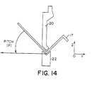
- Fig. 14 illustrates a workpiece 17 after completion of a 90 degree bend with bend-following, compressed between a tool punch 20 and a die 22.
- Workpiece 17 is now ready to be unloaded from the die space, by moving in a -Z direction, a -Y direction and in the +P direction (i.e., by increasing the pitch P to bring the workpiece down towards a horizontal position).
- the goal position of workpiece 17 is a position at which the workpiece is unloaded from the die space, in a substantially horizontal position, and away from the tool punch 20 and die 22.
- tooling expert 43 see Fig.
- planning/control system 38 may be provided with a fine motion planning module 43a which generates a motion plan that includes a list of sequential movements to be performed by a robot to perform either or both of (1) loading workpiece 17 into the die space, and (2) unloading workpiece 17 from the die space after a bend has just been completed.
- a fine motion planning module 43a which generates a motion plan that includes a list of sequential movements to be performed by a robot to perform either or both of (1) loading workpiece 17 into the die space, and (2) unloading workpiece 17 from the die space after a bend has just been completed.
- Each complete sequential list of movements is integrated with the gross motion plans produced by motion expert 44.
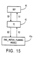
- Fig. 15 provides an illustration of bend sequence planner 40, tooling expert 43, and fine motion planning module 43a, and the dialogue that is performed between those modules throughout the generation of a plan by the planning/control system 38 illustrated in Fig. 4.
- bend sequence planner 40 forwards a query to tooling expert 43, along with a flag called CALL_FINE_MOTION which is set to either TRUE or FALSE. If CALL_FINE_MOTION is set to TRUE, tooling expert 43 is instructed to compute a fine motion path/plan. If the flag is FALSE, a fine motion plan will not be computed, and other tooling expert operations are performed.
- the setting of the flag to FALSE may be useful, e.g., if bend sequence planner 40 already knows the fine motion plan since it was previously computed for an identical bend.
- fine motion planning module 43a If CALL_FINE_MOTION flag is TRUE, tooling expert 43 then sends a query Q2 to fine motion planning module 43a, causing fine motion planning module 43a to be executed. Fine motion planning module 43a then returns, in response R2, a variable FINE_MOTION_COST to tooling expert 43. The variable is 0 if a fine motion plan could be generated, or infinity if a fine motion plan could not be generated. In addition, if a fine motion plan can be generated, fine motion planning modules 43a also returns, in response R2, a FINE_MOTION_PLAN data structure which includes a list of movements in sequence to be performed by the robot in order to bring the workpiece from an initial position q i to a goal position q g .
- the FINE_MOTION_PLAN data structure may include, e.g., two lists, the first list representing the sequence of movements to be performed in order to load the workpiece into the die space, and the second list comprising a sequence of movements to be performed in order to unload the workpiece from the die space after the bend has been completed with bend-following.
- Each of the movements listed in the second (unload) list of movements provided in the example FINE_MOTION_PLAN data structure comprises a relative motion vector in C-space, and thus represents the movement of the combined robot and workpiece 16/17 as a point in C-space.
- Each relative motion vector is given in terms of P in degrees, Y in mm, Z in mm. Accordingly, the first movement in the unload list, which is (0.00 0.00 -30.00), indicates a downward movement of the workpiece by 30 mm (in the -Z direction) from its previous position.
- the next relative motion vector (0.00 -50.00 0.00) indicates a movement of the workpiece to take the workpiece out of the die space (toward the left in Fig. 14) by 50 mm.
- the third relative motion vector (5.00 0.00 -5.00) indicates that the workpiece is being moved in pitch down towards a horizontal position by 5° and simultaneously moved down in the Z direction by 5 mm.
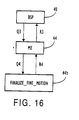
- Fig. 16 illustrates several modules related to the finalization of the fine motion plans, including the integration of the fine motion plans with the gross motion plans to form the overall sequence of movements to be performed.
- the figure shows a bend sequence planner 40, a motion expert 44 and a finalize fine motion module 44b.
- Bend sequence planner 40 puts all the fine motion plans together in a sequence, once all of the bends in a bend sequence have been generated and the search process performed by bend sequence planner 40 has been completed.
- the resulting fine motion plans are forwarded to motion expert 44, along with other motion-related information, in a query Q3.
- Motion expert 44 then forwards a data structure FINE_MOTION_SEQUENCE to finalize fine motion module 44b in query Q4.
- the finalize fine motion module 44b then converts the relative C-space motion vectors present in the FINE_MOTION_SEQUENCE data structure to relative motion vectors in TCP robot world coordinates.
- the finalize fine motion module 44b then forwards, in response R4, a FINE_MOTION_POSITION data structure, along with motion commands to moving expert 44.
- the data structure includes relative motion vectors in TCP robot world coordinates, such relative motion vectors indicating the fine motion position commands that will be sent to the lower level robot trajectory planner for execution of the fine motion plan.
- Motion expert 44 then takes the FINE_MOTION_POSITION data and integrates the same with the gross motion commands, to form a complete integrated gross and fine motion command structure, in TCP world coordinates, which can be forwarded to a lower level robot trajectory planner for execution of the movements.
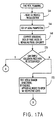
- Figs. 17A-17B comprise a flow chart of a fine motion planning process that may be performed by fine motion planning module 43a provided within tooling expert 43 of the planning/control system 38 illustrated in Fig. 4.
- a first step S64 of the fine motion planning process the 3D models of the punch tool and of the workpiece are read, and several initialization steps are performed.
- the goal parameters are set up based upon the tool and part geometry and the desired clearance. The goal parameters are indicated in C-space, and indicate the goal position q g , e.g., q g (2) as shown in Fig. 8.
- Figs. 17A-17B plans the unloading of a workpiece from a die space, and thus plans a path of movement from a position q i (2) to a goal position q g (2) as illustrated in Fig. 8.
- a bounding box is computed which surrounds the part inside of the bend line (i.e., in the tool concavity inside the bend line).
- the bounding box surrounds the workpiece in its present state bent at the present point in the bend sequence.
- the key geometric features, such as the height and width, of the bounding box are then computed.
- step S70 a determination is made as to whether a simple collision-free path can be determined, by determining if the key features (the height and width of the bounding box) satisfy constraints imposed by the tool geometry and the die opening.
- step S70 the process proceeds from step S70 to step S72, at which point the process will test several intelligent search directions to determine if such intelligent search directions are feasible.
- the feasible intelligent search directions are then appended as nodes to an OPEN list with respective costs corresponding to each appended node.
- Step S72 rapidly produces nodes which are close to the goal position.
- the intelligent search directions are indicated in terms of virtual configuration space (VC-space) relative vectors, and are tested to see if they are feasible by performing a negative intersection of the intermediate bent workpiece (at its present shape in the bend sequence) with the punch tool. If the negative intersection indicates that a collision would occur between the intermediate workpiece and the punch tool, then the node is not feasible. Otherwise, the node is feasible and is added to the OPEN list.
- VC-space virtual configuration space
- step S72 the process proceeds to step S78, where an A* fine motion search is performed until the goal is reached or the OPEN list is empty. Then, in step S80, a determination is made as to whether the goal was reached. If the goal was reached, the process proceeds to step S76, where the fine motion planning module returns information including FINE_MOTION_COST and FINE_MOTION_PLAN to the tooling expert. If the goal was not reached as determined at step S80, the process proceeds to step S82, and a FINE_MOTION_COST of infinity is sent to the tooling expert.
- VC-space virtual configuration space
- Fig. 18 is a flow chart illustrating the steps performed by the intelligent search algorithm which is indicated in step S72 of the fine motion planning process illustrated in Figs. 17A-17B.
- a first step S84 of the intelligent search algorithm the process initializes several step sizes.
- the relative motion vector V corresponding to a first proposed intelligent search direction is set to [0,0,-dZ] in step S86.
- step S88 the part is moved in the modeling realm by V to some new position S'.
- step S90 a collision test is performed, i.e., a negative intersection is performed between the part and the tool, to determine if a collision would occur by moving the part to the new position S'. If a collision would occur by making such a movement, in step S110, the previous collision-free (non-initial) node (if any exists at the present point in the process) is appended to the OPEN list. Then, in step S108, the value stepY is incremented by a certain amount (skipping O). If stepY is already +5 at this point in the process, then the process will exit and return to the fine motion planning process.
- step S92 determines whether a collision would occur by moving the part to the new position S'. If it was determined in step S90 that no collision would occur by moving the part to the new position S', the process proceeds to step S92, at which point a flag Progress_Y is reset. The process then proceeds to step S94, where the part is moved (in the modeling domain) by [0,-dY,0]. A determination is made in step S96 as to whether a collision would occur by moving the part in the manner indicated in step S94. If a collision would occur, the process proceeds to step S114. If a collision would not occur, the process proceeds to step S98, where the flag Progress_Y is set. After step S98, in step S100 a determination is made as to whether the position of the part, in the modeling realm, has reached a goal position in the Y direction. If the part has not reached its goal position in the Y direction, the process returns to step S94, at which point the part will be moved by an additional amount [0,-dY,0].
- step S114 the process proceeds to step S114 at which point the previous collision-free (non-initial) node will be appended to the OPEN list.
- step S116 a determination is made as to whether the Progress_Y flag is presently set to 1. If the Progress_Y flag is set to 1, the process proceeds to step S118, where the part is moved by [dP,(2*dY),-dZ]. The process then proceeds to step S112 to test if a collision would likely occur as a result of the movement indicated in step S118. If a collision would not occur, then the process proceeds from step S112 to step S92. If a collision would occur as determined in step S112, the process proceeds to step S104, where the part is reset to the previous S' position. The process then proceeds directly to step S88 where the part will be moved by the vector V, to a new position S'.
- step S100 If a determination is made at step S100 that the goal position along the Y direction has been reached, then the process proceeds to step S102 where the present node, indicative of the last set of movements for which a collision was not detected, is appended to OPEN list. The process then returns to the fine motion planning process illustrated in Figs. 17A-17B, and thus is ready for the A* motion search performed in step S78.
- Fig. 19 illustrates the A* fine motion algorithm which is indicated in step S78 of the fine motion planning process illustrated in Fig. 17A-17B.
- a determination is made as to whether the OPEN list empty. If the OPEN list is empty, the process proceeds to step S122, where the search will exit with an error indication. If the OPEN list is not empty, the process proceeds from step S120 to step S124, at which point the node having the smallest cost is taken from the OPEN list and put on a CLOSED list. This node is called n i .
- a determination is made in step S126 as to whether the node and n i is at the goal.
- step S128 the process proceeds directly to step S128, where the solution path is generated. If the node n i is not at the goal, the process proceeds from step S126 to step S130, where the node n i is expanded to obtain feasible neighborhood nodes which form the successor nodes n j of the parent node n i .
- the successor nodes n j are appended to the OPEN list with their respective costs.
- the neighborhood nodes may comprise a plurality of (i.e., 26) neighborhood positions surrounding in three dimensions the position of the workpiece at the parent node n i . In order to determine if each neighborhood node is feasible, and whether each node should be added to the OPEN list, collision checking is performed.
- the neighborhood node is appended to the OPEN list along with its costs.
- the algorithm uses the euclidian distance from the particular neighborhood node to the goal node as a measure of cost, such cost being an h cost. It is noted that a value indicative of a k cost could be also determined and associated with each successor node. However, in the illustrated embodiment, no k cost is utilized, so that the computation time associated with the A* search may be minimized.
- Fig. 20 illustrates the relevant portions of sequencer/controller 46 which are utilized to control the movements of the robot, and the various hardware and sensors 47 corresponding thereto.
- Sequencer/controller 46 includes, among other components, a robot task 52 which is coupled to a general motion module 54 and a sensor-based motion module 56.
- the general motion module may include a general motion library of functions
- the sensor-based motion module may comprise a sensor-based motion library of functions.
- Each of the general motion and sensor-based motion modules is connected to a trajectory generator 60, which is in turn connected to an inverse kinematics module 58.
- a filter 62 which may comprise a digital low pass filter implemented with software code, has an output which is connected to an input of sensor-based motion module 56.
- Each of the components of the sequencer/controller 46 is connected to hardware/sensors 47 via appropriate device drivers and hardware interfaces which may be implemented in accordance with the related application, U.S. Patent Application No. 08/338,113, entitled "Intelligent System for Generating and Executing a Sheet Metal Bending Plan” by David Alan Bourne et al., and further as disclosed in the program documentation for the CHIMERA II Real-Time Programming Environment, Version 1.02 (October 24, 1990) by David B. Stewart et al., issued by the Carnegie Mellon University, Pittsburgh, Pennsylvania.
- Inverse Kinematics module 58 is connected, via an appropriate device driver mechanism, to one or more to robot servo controllers 48, each of which is in turn connected to robot 16.
- Filter 62 is connected to one or more A/D boards 50, each of which is connected to one or more sensors 64.
- Each robot servo controller 48 is connected directly to sensor-based motion module 56 via a line 49, which is utilized to carry readings from a robot servo controller 48 regarding the five axis positions of robot 16, so that sensor-based motion control module 56 may make any necessary modifications to the position information to accommodate any inherent limitations of the robot, or so that robot sensor-based control module 56 will know whether the robot is actually moving in accordance with the control commands being given.
- Each of general motion control module 54 and sensor-based motion control module 56 is controlled by robot task 52 of sequencer/controller 46, and each direct movement of robot 16 from various initial positions to goal positions.
- Each of the motion control modules 54, 56 direct movement of the robot by outputting a list of knot points, in Cartesian space, through which robot 16 should be moved in order to go from an initial start position Q i to a goal position Q g .
- the list of knot points, each point corresponding to a consecutive position along a free path from Q i to Q g is then input to a trajectory generator 60 which calculates a spline function for each coordinate of the robot 16.
- Each spline function extends between a pair of adjacent knot points.
- the resulting spline functions are then input to inverse kinematics module 58 in order to convert the appropriate information to joint space representations for controlling movement of the robot in joint coordinates.
- the one or more robot servo controllers 48 perform trajectory tracking of the respective axes of the robot in conformance with the spline functions input thereto.
- Sensor-based motion control module 56 is provided for controlling motion of the robot in situations where sensing is needed, such as in performing a bend-following operation which corresponds to step S92 of the flow chart shown in Fig. 7 and step S8 of the overall bending process illustrated in Fig. 5.
- a sensing feedback mechanism is illustrated in Fig. 20, so that sensor-based motion plans may be executed.
- the sensing feedback mechanism comprises one or more sensors 64, one or more A/D boards 50, and a filter 62, connected in cascade, to sensor-based motion control module 56 via a sensing feedback line 63.
- Each of the one or more sensors 64 has its output connected to one or more A/D boards for converting the analog signals produced by the sensors to digital signals that can be manipulated in digital form by sequencer/controller 46.
- Filter 62 is placed between the output A/D boards 50 and an input of sensor-based motion control module 56, for the purpose of filtering out any unwanted (e.g., high frequency) noise which may be present within the signals produced by the sensors
- each of robot servo controllers 48 may comprise a Creonics motion controller Model: MCCII S/W/ROM#255991.0 which is available from Allen Bradley.
- each robot servo controller 48 is capable of calculating robot actuator coordinates, i.e, the actual positioning of the robot actuators, and, accordingly, outputs appropriate signals to the micro switches and stepping motors of robot 16 to control movement thereof.
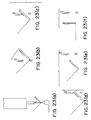
- Figs. 22-27 illustrate snapshots of a modelled workpiece as the workpiece relates to the punch tool and die when unloading the workpiece after a bend with bend-following has been executed.
- the examples illustrate the general motions that will be made during disengagement of the bend press and unloading of the workpiece from the die space.
- the die is lowered, disengaging the die from the tool punch, and the workpiece is simultaneously lowered in the Y direction. Then, the workpiece is pulled back in the Y direction, and the pitch of the workpiece is increased bringing the workpiece toward a horizontal position.
- the workpiece ends up in the goal position as indicated in the lower right hand corner of Fig. 22.
- the workpiece begins in its loaded bent state in view (a), and then proceeds to view (b), by simultaneously lowering the workpiece in the Z direction and disengaging the die from the punch tool. Then, the workpiece is moved as indicated in view (c) in the -Y direction until it contacts the punch tool. The workpiece is simultaneously moved in the -Y and -Z directions until it clears the punch tool as indicated in view (d). Then, the workpiece is moved in the -Y direction until it reaches the position as indicated in the view (e). Then, the pitch of the workpiece is increased bringing the workpiece toward a horizontal position as indicated in view (f).
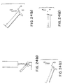
- Fig. 24 illustrates a workpiece in view (a) starting in its engaged bent state.
- the die is lowered and the workpiece is lowered slightly in the -Z direction as indicated in view (b).
- the die is lowered, the workpiece is simultaneously lifted upward in the +Z direction because of the presence of a down flange located at the bottom right corner portion of the workpiece.
- the workpiece is then moved in the -Y direction until it contacts the die as indicated in view (c).
- the pitch of the workpiece is then simultaneously moved in the positive direction while the workpiece is moved in the -Y direction, resulting in the workpiece having a position as indicated in view (d).
- Fig. 25 illustrates a workpiece starting in view (a) at a position at which the die has already been disengaged.
- the die is lowered, and in view (c), the workpiece is moved in the positive pitch direction while backing the workpiece out of the die space in the -Y direction, until it reaches the goal position as indicated in view (d).
- the workpiece shown in Fig. 26 has a channel bend that was just formed by a goose neck punch. When there is a channel bend, or a bend similar to a channel bend, it is important to synchronously counteract the down action of the die with an upward action of the workpiece. Thus, when the die is lowered in view (a) the workpiece should be raised in an upward direction.
- the sequencer/controller may be designed to perform active compliance in order perform this step, which includes intentionally keeping the workpiece in contact with the goose neck punch as it is slid along the surface of the goose neck punch until the workpiece clears the bottom tip surface of the goose neck punch. Once the workpiece clears the bottom tip surface of the punch, the workpiece may be moved in the -Y direction while moving the workpiece in the positive pitch direction until the workpiece reaches its goal position as indicated in views (c) and (d).
- Fig. 27 illustrates a workpiece which must be simultaneously moved in the upward (+Z) direction during disengagement of the die in view (a), and which must be slid down in the -Z, +Y directions (optionally using active compliance), as indicated in each of views (b), (c) and (d).
- the workpiece may be moved in the -Y direction and in the + pitch direction until it reaches its goal position as shown in view (f).
- Fig. 21 illustrates a robot 16 in joint space coordinates with respect to a robot origin, and in cartesian space coordinates with respect to a designated world origin.
- the movements of a robot provided in a BM100 bending work station are expressed by five coordinates (X, Y, Z, A, B) in joint space, which relate a TCP (Tool Center Point) to the robot origin.
- TCP Tool Center Point
- the robot is controlled by specifying the position of the robot TCP in joint space (X, Y, Z, A, B), while positioning of the robot by the motion planning systems frequently must be represented in cartesian coordinates with respect to a world origin.
- the system should be provided with a device for performing a forward kinematics calculation, thus converting a position of the robot represented in joint coordinates (X, Y, Z, A, B) to world coordinates (X, Y, Z, Pitch, Yaw).
- the forward kinematics solution determines the robot hand position in world coordinates from known joint angles.
- the reverse kinematic solution determines a set of joint values that would move the robot hand to a position specified in world coordinates.
- the robot and press brake motions may be modeled to using Denavit-Hartenberg (D-H) convention to represent transformations between subsequent links. While following D-H convention, a Jacobean matrix may be computed, which relates differential changes in joint space to changes in world space at a particular robot configuration. More detailed information regarding forward and reverse kinematics (and Robotics Mechanics and Control generally) is given by John J. Craig in “Introduction to Robotics Mechanics and Contol," Second Ed., Addison-Wesley Publishing Co., Reading, MA (1989), the content of which is expressly incorporated by reference herein in its entirety.
- D-H Denavit-Hartenberg
Description

Claims (46)
- A method for planning motion of a robot (16) within free space, confined by obstacles (22,18,24) from an initial position (Q;(1),Q;(2),Qi(3),Qi(4)) to a goal position (Qg(1),Qg(2),Qg(3),Qg(4)), performed in a computer having at least one processor and a memory, said method comprising:characterised in that said method further comprising:proposing, for an mth movement within a sequence of movements, a plurality of proposed movements (10,12) to be made by the robot (16);modelling at least a portion of the obstacles (72,79,76) that confine the free space (73);determining (528) whether a collision will occur between the robot (16) and an obstacle (72,79,76) for a proposed movement being executed as said mth movement; andgenerating (540) a plan including said sequence of movements, by choosing, for each movement in said sequence of movements, a proposed movement that will not result in a collision (528) and that will bring the robot (16) closer (544,546) to the goal position (Qg(1),Qg(2),Qg(3),Qg(4)),modelling at least a portion of the robot (16);fine motion planning (43a) for planning a plurality of free space fine motion solution paths that extend between a plurality of respective pairs of positions, qi and qg; andgross motion planning (44a) for planning a plurality of free space gross motion solution paths that extend between a plurality of respective pairs of positions, Qi and Qg.
- The method according to claim 1, characterised in that said robot (16) comprises a robot for holding and manoeuvring said workpiece (17) throughout a sequence of bending operations (qi(1),qg(1),qp,qi(2),qg(2)) to be performed by a bending apparatus (20,22).
- The method according to claim 1, characterised in that a cost is estimated (S44,S46,S48) to be associated with each proposed movement, whereby said generating step (S40) comprises generating a plan including said sequence of movements , by choosing, for each movement in the sequence of movements, a proposed movement that will not result in a collision (S28), that will bring the robot closer to the goal position (Qg(1),Qg(2),Qg(3),Qg(4)), and that has a lowest estimated cost.
- The method according to claim 3, characterised in that the estimated cost for a particular proposed movement comprises a Euclidian distance (S44) to the goal position (Qg(1),Qg(2),Qg(3),Qg(4)) from the position of the robot after said particular proposed movement is made as said mth movement.
- The method according to claim 3, characterised in that the estimated cost for a particular proposed movement comprises an estimated value (S46) indicative of the robot travel time to move from a position after an (m-1)th movement is made to a position of the robot after said particular proposed movement is made.
- The method according to claim 1, characterised in that before said proposing step, a plurality of movements is specified in C-space (29) for an mth movement in said sequence of movements, and identifying which ones of the specified plurality of movements are feasible by performing collision checking (S28), said proposing step comprising proposing movements from among the movements identified as feasible.
- The method according to claim 6, characterised in that the specified plurality of movements specified for an mth movement in said sequence of movements comprises a plurality of movements in directions which collectively surround the position of the robot at the (m-1) th movement in said sequence of movements.
- The method according to claim 6, characterised in that the specified plurality of movements for an mth movement in said sequence of movements comprises movements in a plurality of intelligent movement directions.
- The method according to claim 8, characterised in that said method plans a motion (S94; qf->qg(2)) of said robot (16) in order to unload a malleable workpiece (17) from a tooling punch (20) of a bending apparatus (22) after completion of a bend, said intelligent directions comprising a downward movement of said robot causing said workpiece to move downward.
- The method according to claim 8, characterised in that said method plans a motion (S94; qf->qg (2)) of said robot (16) in order to unload a malleable workpiece from a tooling punch (20) of a bending apparatus (22) after completing of a bend, said intelligent directions comprising a backward movement of said robot causing said workpiece to be backed out of the bending apparatus.
- The method according to claim 8, characterised in that said method plans a motion (S94; qf->qg(2)) of said robot (16) in order to unload a malleable workpiece from a tooling punch (20) of a bending apparatus (22) after completion of a bend, said intelligent directions comprising a movement of said robot causing said workpiece to change in pitch from an inclined position towards a horizontal position.
- The method according to claim 8, characterised in that said method plans a motion (S94; qf-qg(2)) of said robot (16) in order to unload a malleable workpiece from a tooling punch (20) of a bending apparatus (22) after completion of a bend, said intelligent directions comprising a movement of said robot causing said workpiece to be moved downward, to be moved backward away from said being apparatus, and to drop in pitch from an angled position towards a horizontal position.
- The method according to claim 1, characterised in that said method further comprises:forming an m-tree representation (12; Fig.11B) of a work space of said robot; andcomputing maximal overlapping rectangloids ((a,d,f,t,n,p,g,s), (m,a,t,j,v,b,r,i), (j,t,f,h,k,w,e,y), (I,o,q,x,m,a,c,v)) within the free space of said m-tree representation of said workspace.
- The method according to claim 13, characterised in that said m-tree representation is an octree representation.
- The method according to claim 13, characterised in that said maximal overlapping rectangloids comprise maximal overlapping parallelepipeds.
- The method according to claim 13, characterised in that said proposing step comprises proposing for an mth movement, a set of movements of the robot (16) to locations that fall within a maximal overlapping rectangloid within which the robot (16) is located immediately after the (m-1 )th movement of said sequence of movements.
- The method according to claim 16, characterised in that said set of movements comprises:translating said robot (16) to any one of eight corners of a presently occupied maximal overlapping rectangloid; andmoving said robot along any one of a plurality of predetermined directions which bring said robot to a position that corresponds to said goal position (Qg(1), Qg(2), Qg(3), Qg(4)).
- The method according to claim 16, characterised in that said set of movements comprises:moving said robot in a first of three orthogonal directions to a position along the first orthogonal direction which corresponds to said goal position;moving said robot (16) in a second of the three orthogonal directions to a position along the second orthogonal direction which corresponds to said goal position;moving said robot (16) in a third of the three orthogonal directions to a position along the third orthogonoal direction which corresponds to said goal position;moving said robot (16) in order to adjust a pitch of a gripper of said robot; andmoving said robot (16) in order to adjust both pitch and yaw of the gripper (19) of said robot.
- The method according to claim 16, characterised in that said set of movements comprises moving along one of a plurality of orthogonal directions only when such movement would bring the robot to an orthogonal position that corresponds to the goal position (Qg(1),Qg(2),Qg(3),Qg(4)).
- The method according to claim 1, characterised in that said fine motion planning comprises performing said steps of proposing, modelling, determining and generating, for each pair of position qi and qg, said proposing step comprising specifying a plurality of movements in C-space (29) for the mth movement and identifying which ones of the specified plurality of movements are feasible by performing collision checking (S70).
- The method according to claim 1, characterised in that said gross motion planning comprises performing said steps of proposing, modelling, determining and generating, for each pair of positions Qi and Qg, said proposing step comprising proposing a set of movements within a maximal overlapping parallelepiped within the free space of said robot (16).
- The method according to claim 20, characterised in that said gross motion planning comprises performing said steps of proposing, modelling, determining and generating, for each pair of positions Qi and Qg, said proposing step comprising proposing a set of movements within a maximal overlapping parallelepiped within the free space of said robot (16).
- The method according to claim 2, further comprising:calculating (S28) whether a simple collision-free path can be determined;forming a plan including movements for traversing the simple collision-free path; andinhibiting operation of said steps of proposing, determining and generating.
- A system (38) for planning motion of a robot (16) within a free space confined by obstacles (72,76,79) from an initial position (Qi(1),Qi(2),Qi,(3),Qi;(4)) to a goal position (Qg(1),Qg(2),Qg(3),Qg(4)), said system comprising:characterised in thatproposing means for proposing for an mth movement within a sequence of movements, a plurality of proposed movements (10,12) to be made by said robot (16);modelling means for modelling at least a portion of the obstacles (72,76,79) that confine the free space (73);determining means (S28) for determining whether a collision will occur between said robot (16) and an obstacle (72,76,79) for a proposed movement being executed as said mth movement; andgenerating means (S40;40) for generating a plan including said sequence of movements, by choosing, for each movement within said sequence of movements, a proposed movement that will not result in a collision (S28) and that will bring said robot (16) closer (S44,S46) to the goal position (Qg(1), Qg(2), Qg(3), Qg(4));said modelling means further models at least a portion of said robot (16);said system for planning motion further comprising:fine motion planning means (43a) for planning a plurality of free space fine motion solution paths that extend between a plurality of respective pairs of positions qi and qg; andgross motion planning means (44a) for planning a plurality of free space gross motion solution paths that extend between a plurality of respective pairs of positions Qi and Qg.
- The system according to claim 24, characterised in that said robot (16) comprises a robot for holding and manoeuvring said workpiece (17) throughout a sequence of bending operations (qi(1), qg(1), qp, qi(2), qg(2)) to be performed by a bending apparatus (20,22).
- The system according to claim 24, characterised in that said system further comprises estimating means (S44,S46,S48) for estimating a cost to be associated with each proposed movement, whereby said generating means (S44,S46,S48) comprise means for generating (S40) a plan including said sequence of movements, by choosing (S28), for each movement in said sequence of movements, a proposed movement that will not result in a collision, that will bring the robot closer to the goal position (Qg(1), Qg(2), Qg(3), Qg(4)) and that has a lowest estimated cost.
- The system according to claim 26, characterised in that the estimated cost for a particular proposed movement comprises a Euclidian distance (S44) to the goal position (Qg(1), Qg(2), Qg(3), Qg(4)) from the position of the robot after said particular proposed movement is made as said mth movement.
- The system according to claim 26, characterised in that the estimated cost for a particular proposed movement comprises an estimated value (S46) indicative of the robot's travel time from an (m-1 )th movement to the position of the robot after said particular proposed movement is made as said mth movement.
- The system according to claim 24, characterised in that the system further comprises specifying means for specifying a plurality of movements in C-space (29) for an mth movement in said sequence of movements and identifying means for identifying which ones of the specified plurality of movements are feasible by performing collision checking (S28), said proposing means comprising means for proposing movements from among the movements identified by said identifying means as feasible.
- The system according to claim 29, characterised in that the specified plurality of movements specified for an mth movement in a sequence of movements comprises a plurality of movements and directions which collectively surround a position of the robot at the (m-1)th movement in said sequence of movements.
- The system according to claim 29, characterised in that the specified plurality of movements for an mth movement in said sequence of movements comprises movements in a plurality of intelligent movement directions.
- The system according to claim 31, characterised in that said system further comprises means for planning motion of said robot in order to unload (S94; qf->qg(2)) a malleable workpiece (17) from a tooling punch (20) of a bending apparatus (22) after completion of a bend, said intelligent directions comprising a downward movement of said robot causing said workpiece to move downward.
- The system according to claim 31, characterised in that said system further comprises means for planning motion of said robot in order to unload (S94; qf->qg(2)) a malleable workpiece from a tooling punch (20) of a bending apparatus (22) after completion of a bend, said intelligent directions comprising a backward movement of said robot causing said workpiece to be backed out of the bending apparatus.
- The system according to claim 31, characterised in that said system further comprises means for planning motion of said robot in order to unload (S94; qf-qg(2)) a malleable workpiece (17) from a tooling punch (20) of a bending apparatus (22) after completion of a bend, said intelligent directions comprising a movement of said robot causing said workpiece to change in pitch from an angled position towards a horizontal position.
- The system according to claim 31, characterised in that said system further comprises means for planning motion of said robot in order to unload (S94; qf->qg(2)) a malleable workpiece (17) from a tooling punch (20) of a bending apparatus (22) after completion of a bend, said intelligent directions comprising a movement of said robot causing said workpiece to be moved downward, to be moved backward and away from said bending apparatus, and to drop in pitch from an angled position towards a horizontal position.
- The system according to claim 24, characterised in that said system further comprises:forming means for forming an m-tree representation (12;fig.11B) of a work space of said robot; andcomputing means for computing maximal overlapping rectangloids ((a,d,f,t,n,p,g,s), (m,a,t,j,n,b,v,i), (j,t,f,h,k,w,e,y), (I,o,q,x,m,a,c,v) within the free space of said m-tree representation of said work space.
- The system according to claim 36, characterised in that said m-tree representation is an octree representation.
- The system according to claim 36, characterised in that said maximal overlapping rectangloids comprise maximal overlapping parallelepipeds.
- The system according to claim 36, characterised in that said proposing means comprises means for proposing, for an mth movement, a set of movements of the robot (16) to locations that fall within a maximal overlapping rectangloid within which the robot (16) is located immediately after the (m-1)th movement of said sequence of movements.
- The system according to claim 39, characterised in that said set of movements comprises:translating said robot (16) to any one of eight corners of a present maximal overlapping rectangloid; andmoving said robot along any one of a plurality of predetermined directions which bring said robot to a position along a predetermined direction that corresponds to said goal position (Qg(1),Qg(2),Qg(3),Qg(4)).
- The system according to claim 39, characterised in that said set of movements comprises:moving said robot (16) in a first of three orthogonal directions to a position along the first orthogonal direction which corresponds to said goal position;moving said robot (16) in a second of the three orthogonal directions to a position along the second orthogonal direction which corresponds to said goal position;moving said robot (16) in a third of the three orthogonal directions to a position along the third orthogonal direction which corresponds to said goal position;moving said robot (16) in order to adjust a pitch of a gripper of said robot; andmoving said robot (16) in order to adjust both the pitch and yaw of the gripper of said robot (16).
- The system according to claim 41, characterised in that said set of movements comprises moving along one of a plurality of orthogonal directions only when the movement would bring the robot to an orthogonal position that corresponds to the goal position (Qg(1),Qg(2),Qg(3),Qg(4)).
- The system according to claim 25, characterised in that said fine motion planning means comprises means for operating said proposing means, modelling means, determining means, and generating means, for each pair of positions qi and qg, said proposing means comprising specifying means for specifying a plurality of movements in C-space (29) for the mth movement and identifying means for identifying which ones of the specified plurality of movements are feasible by performing collision checking (S70).
- The system according to claim 25, characterised in that said gross motion planning means comprises means for operating said proposing means, modelling means, determining means and generating means, for each pair of positions Qi and Qg, said proposing means comprising means for proposing a set of movements within a maximal overlapping parallelepiped within the free space of said robot (16).
- The system according to claim 43, characterised in that said gross motion planning means comprises means for operating said proposing means, modelling means, determining means and generating means, for each pair of positions Qi and Qg, said proposing means comprising means for proposing a set of movements within a maximal overlapping parallelepiped within the free space of said robot (16).
- The system according to claim 25, characterised in that said system further comprises:calculating means for calculating whether a simple collision-free path can be determined;forming means for forming a plan including movements for transversing the simple collision-free path; andinhibiting means for inhibiting operation of said proposing means, determining means, and generating means.
Priority Applications (1)
| Application Number | Priority Date | Filing Date | Title |
|---|---|---|---|
| EP99109178A EP0945227A3 (en) | 1994-11-09 | 1995-11-09 | Method for planning/controlling robot motion |
Applications Claiming Priority (3)
| Application Number | Priority Date | Filing Date | Title |
|---|---|---|---|
| US338115 | 1994-11-09 | ||
| US08/338,115 US5835684A (en) | 1994-11-09 | 1994-11-09 | Method for planning/controlling robot motion |
| PCT/JP1995/002290 WO1996014967A1 (en) | 1994-11-09 | 1995-11-09 | Method for planning/controlling robot motion |
Related Child Applications (1)
| Application Number | Title | Priority Date | Filing Date |
|---|---|---|---|
| EP99109178A Division EP0945227A3 (en) | 1994-11-09 | 1995-11-09 | Method for planning/controlling robot motion |
Publications (2)
| Publication Number | Publication Date |
|---|---|
| EP0738199A1 EP0738199A1 (en) | 1996-10-23 |
| EP0738199B1 true EP0738199B1 (en) | 2000-03-08 |
Family
ID=23323475
Family Applications (2)
| Application Number | Title | Priority Date | Filing Date |
|---|---|---|---|
| EP99109178A Withdrawn EP0945227A3 (en) | 1994-11-09 | 1995-11-09 | Method for planning/controlling robot motion |
| EP95936761A Expired - Lifetime EP0738199B1 (en) | 1994-11-09 | 1995-11-09 | Method for planning/controlling robot motion |
Family Applications Before (1)
| Application Number | Title | Priority Date | Filing Date |
|---|---|---|---|
| EP99109178A Withdrawn EP0945227A3 (en) | 1994-11-09 | 1995-11-09 | Method for planning/controlling robot motion |
Country Status (5)
| Country | Link |
|---|---|
| US (3) | US5835684A (en) |
| EP (2) | EP0945227A3 (en) |
| JP (1) | JPH09509513A (en) |
| DE (1) | DE69515464T2 (en) |
| WO (1) | WO1996014967A1 (en) |
Families Citing this family (142)
| Publication number | Priority date | Publication date | Assignee | Title |
|---|---|---|---|---|
| US6324476B1 (en) * | 1987-11-20 | 2001-11-27 | Philips Electronicsnorth America Corporation | Method and apparatus for identifying or controlling travel to a rendezvous |
| US5761940A (en) | 1994-11-09 | 1998-06-09 | Amada Company, Ltd. | Methods and apparatuses for backgaging and sensor-based control of bending operations |
| DE69529607T2 (en) | 1994-11-09 | 2003-09-18 | Amada Co | INTELLIGENT SYSTEM FOR THE MANUFACTURE AND EXECUTION OF A METAL PLATE BENDING PLAN |
| US5835684A (en) * | 1994-11-09 | 1998-11-10 | Amada Company, Ltd. | Method for planning/controlling robot motion |
| DE69529603T2 (en) * | 1994-11-09 | 2003-06-26 | Amada Co | SHEAR FORCE MEASURING SYSTEM |
| US5692184A (en) * | 1995-05-09 | 1997-11-25 | Intergraph Corporation | Object relationship management system |
| US5864482A (en) * | 1996-05-06 | 1999-01-26 | Amadasoft America, Inc. | Apparatus and method for managing distributing design and manufacturing information throughout a sheet metal production facility |
| US5822207A (en) * | 1996-05-06 | 1998-10-13 | Amadasoft America, Inc. | Apparatus and method for integrating intelligent manufacturing system with expert sheet metal planning and bending system |
| US5971589A (en) | 1996-05-06 | 1999-10-26 | Amadasoft America, Inc. | Apparatus and method for managing and distributing design and manufacturing information throughout a sheet metal production facility |
| US5886897A (en) | 1996-05-06 | 1999-03-23 | Amada Soft America Inc. | Apparatus and method for managing and distributing design and manufacturing information throughout a sheet metal production facility |
| US5828575A (en) | 1996-05-06 | 1998-10-27 | Amadasoft America, Inc. | Apparatus and method for managing and distributing design and manufacturing information throughout a sheet metal production facility |
| IT1283019B1 (en) * | 1996-05-16 | 1998-04-03 | Salvagnini Italia Spa | MANAGEMENT METHOD OF A WORKING ISLAND INCLUDING A ROBOT SUBJECTED TO A BENDING PRESS FOR PROCESSING SHEETS. |
| US6004016A (en) * | 1996-08-06 | 1999-12-21 | Trw Inc. | Motion planning and control for systems with multiple mobile objects |
| IT1284548B1 (en) * | 1996-09-18 | 1998-05-21 | Salvagnini Italia Spa | METHOD FOR TRANSPORTING SHEETS TO A WORK ISLAND INCLUDING A MACHINE TOOL AND A ROBOT |
| US6154723A (en) * | 1996-12-06 | 2000-11-28 | The Board Of Trustees Of The University Of Illinois | Virtual reality 3D interface system for data creation, viewing and editing |
| US6233538B1 (en) * | 1997-09-11 | 2001-05-15 | Amada America, Inc. | Apparatus and method for multi-purpose setup planning for sheet metal bending operations |
| DE69931087T2 (en) * | 1998-02-03 | 2006-09-21 | Kabushiki Kaisha Opton | bender |
| JP3781557B2 (en) * | 1998-06-24 | 2006-05-31 | 本田技研工業株式会社 | Method for determining the optimal transfer route of goods |
| US6470228B1 (en) * | 1999-06-23 | 2002-10-22 | Vought Aircraft Industries, Inc. | Material management system and method |
| DE19939137A1 (en) * | 1999-08-18 | 2001-03-08 | Bosch Gmbh Robert | Device and method for generating a setpoint for controlling a drive |
| US6856863B1 (en) * | 2000-07-27 | 2005-02-15 | Applied Materials, Inc. | Method and apparatus for automatic calibration of robots |
| JP3715537B2 (en) * | 2001-02-19 | 2005-11-09 | 本田技研工業株式会社 | Interference avoidance method and program for articulated robot |
| JP3782679B2 (en) * | 2001-05-09 | 2006-06-07 | ファナック株式会社 | Interference avoidance device |
| US7474781B2 (en) * | 2001-09-20 | 2009-01-06 | International Business Machines Corporation | Image based bar-code reading and robotic registration apparatus for use in automated tape library systems |
| US6980692B2 (en) * | 2001-09-20 | 2005-12-27 | International Business Machines Corporation | Method and apparatus for dynamic thresholding of grayscale images to delineate image attributes |
| US7269284B2 (en) * | 2001-09-20 | 2007-09-11 | International Business Machines Corporation | Method and apparatus using dual bounding boxes as dynamic templates for cartridge rack identification and tracking |
| US6466843B1 (en) * | 2001-10-16 | 2002-10-15 | General Electric Company | Method and apparatus for lifting objects |
| WO2003040841A1 (en) * | 2001-11-09 | 2003-05-15 | Amada Company, Limited | Compound processing system for sheet metal processing |
| US6832139B2 (en) * | 2002-03-21 | 2004-12-14 | Rapistan Systems Advertising Corp. | Graphical system configuration program for material handling |
| US20050220582A1 (en) * | 2002-09-13 | 2005-10-06 | Tokyo Electron Limited | Teaching method and processing system |
| ATE336741T1 (en) * | 2002-10-18 | 2006-09-15 | Schechtl Maschb Gmbh | SWIVEL BENDING MACHINE AND CORRESPONDING CONTROL METHOD |
| CA2514204C (en) * | 2003-01-31 | 2015-12-15 | Thermo Crs Ltd. | Syntactic inferential motion planning method for robotic systems |
| US6943976B2 (en) * | 2003-09-23 | 2005-09-13 | International Business Machines Corporation | Rezeroing a robot accessor of an automated data storage library |
| US8361013B2 (en) | 2004-04-19 | 2013-01-29 | The Invention Science Fund I, Llc | Telescoping perfusion management system |
| US8353896B2 (en) | 2004-04-19 | 2013-01-15 | The Invention Science Fund I, Llc | Controllable release nasal system |
| US8024036B2 (en) | 2007-03-19 | 2011-09-20 | The Invention Science Fund I, Llc | Lumen-traveling biological interface device and method of use |
| US8092549B2 (en) | 2004-09-24 | 2012-01-10 | The Invention Science Fund I, Llc | Ciliated stent-like-system |
| US8512219B2 (en) | 2004-04-19 | 2013-08-20 | The Invention Science Fund I, Llc | Bioelectromagnetic interface system |
| US9011329B2 (en) | 2004-04-19 | 2015-04-21 | Searete Llc | Lumenally-active device |
| US8337482B2 (en) | 2004-04-19 | 2012-12-25 | The Invention Science Fund I, Llc | System for perfusion management |
| US7129951B2 (en) * | 2004-05-06 | 2006-10-31 | Valve Corporation | Method and system for performing speculative collisions for a video game |
| US8000837B2 (en) | 2004-10-05 | 2011-08-16 | J&L Group International, Llc | Programmable load forming system, components thereof, and methods of use |
| US7398129B2 (en) * | 2004-10-07 | 2008-07-08 | Amada Company, Limited | Representation of sheet metal part models |
| US7158853B2 (en) * | 2004-10-25 | 2007-01-02 | Amada Company, Limited | Pattern recognition for sheet metal part models |
| US7813901B2 (en) * | 2004-10-25 | 2010-10-12 | Amada Company, Limited | Sketch generator for 3D sheet metal part models created by sheet metal part feature operations |
| US7798764B2 (en) | 2005-12-22 | 2010-09-21 | Applied Materials, Inc. | Substrate processing sequence in a cartesian robot cluster tool |
| US7699021B2 (en) | 2004-12-22 | 2010-04-20 | Sokudo Co., Ltd. | Cluster tool substrate throughput optimization |
| US7396412B2 (en) | 2004-12-22 | 2008-07-08 | Sokudo Co., Ltd. | Coat/develop module with shared dispense |
| US7725418B2 (en) * | 2005-01-28 | 2010-05-25 | Honda Motor Co., Ltd. | Responding to situations using multidimensional semantic net and Bayes inference |
| US7512485B2 (en) * | 2005-03-29 | 2009-03-31 | International Business Machines Corporation | Method for routing multiple paths through polygonal obstacles |
| US7370022B2 (en) * | 2005-07-08 | 2008-05-06 | Honda Motor Co. | Building plans for household tasks from distributed knowledge |
| US8019713B2 (en) * | 2005-07-08 | 2011-09-13 | Honda Motor Co., Ltd. | Commonsense reasoning about task instructions |
| US7603330B2 (en) * | 2006-02-01 | 2009-10-13 | Honda Motor Co., Ltd. | Meta learning for question classification |
| US8936629B2 (en) | 2006-04-12 | 2015-01-20 | Invention Science Fund I Llc | Autofluorescent imaging and target ablation |
| US20120035438A1 (en) | 2006-04-12 | 2012-02-09 | Searete Llc, A Limited Liability Corporation Of The State Of Delaware | Path selection by a lumen traveling device in a body tub tree based on previous path |
| FR2900360B1 (en) * | 2006-04-28 | 2008-06-20 | Staubli Faverges Sca | METHOD AND DEVICE FOR SETTING OPERATING PARAMETERS OF A ROBOT, PROGRAM, AND RECORDING MEDIUM FOR THIS METHOD |
| DE102006022483A1 (en) * | 2006-05-13 | 2007-11-29 | Kuka Roboter Gmbh | Method and device for displaying a robot path for supporting a change of location of a support point |
| US8163003B2 (en) | 2006-06-16 | 2012-04-24 | The Invention Science Fund I, Llc | Active blood vessel sleeve methods and systems |
| EP1870211B1 (en) * | 2006-06-22 | 2019-02-27 | Honda Research Institute Europe GmbH | Method for controlling a robot by assessing the fitness of a plurality of simulated behaviours |
| JP2008073830A (en) * | 2006-09-25 | 2008-04-03 | Fanuc Ltd | Robot control device |
| JP4298757B2 (en) * | 2007-02-05 | 2009-07-22 | ファナック株式会社 | Robot mechanism calibration apparatus and method |
| EP1972415B1 (en) * | 2007-03-23 | 2019-01-02 | Honda Research Institute Europe GmbH | Robots with collision avoidance functionality |
| EP1972416B1 (en) * | 2007-03-23 | 2018-04-25 | Honda Research Institute Europe GmbH | Robots with occlusion avoidance functionality |
| EP1974869A1 (en) * | 2007-03-26 | 2008-10-01 | Honda Research Institute Europe GmbH | Apparatus and method for generating and controlling the motion of a robot |
| US8046102B2 (en) * | 2007-05-17 | 2011-10-25 | Fanuc Robotics America, Inc. | Control method for synchronous high speed motion stop for multi-top loaders across controllers |
| JP5060619B2 (en) * | 2007-06-08 | 2012-10-31 | 本田技研工業株式会社 | Motion planning method, motion planning system, and recording medium |
| US7783447B2 (en) * | 2007-11-24 | 2010-08-24 | Kingston Technology Corp. | Chip handler with a buffer traveling between roaming areas for two non-colliding robotic arms |
| KR101372482B1 (en) * | 2007-12-11 | 2014-03-26 | 삼성전자주식회사 | Method and apparatus of path planning for a mobile robot |
| US8571745B2 (en) * | 2008-04-10 | 2013-10-29 | Robert Todd Pack | Advanced behavior engine |
| CN101572029B (en) * | 2008-04-28 | 2012-01-25 | 鸿富锦精密工业(深圳)有限公司 | System and method for simulating robot plate bending |
| DE102008058298B4 (en) * | 2008-04-29 | 2016-01-14 | Siemens Aktiengesellschaft | Method for computer-aided motion planning of a robot |
| DE102008057142B4 (en) * | 2008-04-29 | 2016-01-28 | Siemens Aktiengesellschaft | Method for computer-aided motion planning of a robot |
| CN101959653B (en) * | 2008-07-09 | 2012-10-24 | 松下电器产业株式会社 | Path danger evaluation device |
| US8078445B2 (en) * | 2008-09-30 | 2011-12-13 | Rockwell Automation Technologies, Inc. | Load characterization in servo drive systems |
| KR101021836B1 (en) * | 2008-10-09 | 2011-03-17 | 한국전자통신연구원 | System for cooperation of multiple mobile robot using dynamic behavior binding and method thereof |
| US20100114338A1 (en) * | 2008-10-31 | 2010-05-06 | Gm Global Technology Operations, Inc. | Multi-goal path planning of welding robots with automatic sequencing |
| JP4730440B2 (en) * | 2009-01-01 | 2011-07-20 | ソニー株式会社 | Trajectory planning apparatus, trajectory planning method, and computer program |
| US8024069B2 (en) * | 2009-01-28 | 2011-09-20 | Ge Intelligent Platforms, Inc. | System and method for path planning |
| ATE516930T1 (en) * | 2009-05-15 | 2011-08-15 | Honda Res Inst Europe Gmbh | AUTONOMOUS ROBOTS WITH PLANNING IN UNPREDICTABLE, DYNAMIC AND COMPLEX ENVIRONMENTS |
| KR101667029B1 (en) * | 2009-08-10 | 2016-10-17 | 삼성전자 주식회사 | Method and apparatus of path planing for a robot |
| KR101667030B1 (en) * | 2009-08-10 | 2016-10-17 | 삼성전자 주식회사 | Path planning apparatus of robot and method thereof |
| KR101667031B1 (en) * | 2009-11-02 | 2016-10-17 | 삼성전자 주식회사 | Path planning apparatus of robot and method thereof |
| JP5398489B2 (en) * | 2009-11-20 | 2014-01-29 | 村田機械株式会社 | Autonomous mobile object and its control method |
| US20110153080A1 (en) * | 2009-12-22 | 2011-06-23 | Siemens Product Lifecycle Management Software Inc. | Method and apparatus for industrial robotic pathscycle time optimization using fly by |
| JP5475629B2 (en) * | 2010-01-12 | 2014-04-16 | 本田技研工業株式会社 | Trajectory planning method, trajectory planning system, and robot |
| JP5715840B2 (en) * | 2011-02-04 | 2015-05-13 | 本田技研工業株式会社 | Trajectory planning method, trajectory control method, trajectory planning system, and trajectory planning / control system |
| JP5454491B2 (en) * | 2011-02-25 | 2014-03-26 | 株式会社安川電機 | Work system |
| JP5430796B2 (en) * | 2011-04-14 | 2014-03-05 | 三菱電機株式会社 | Robot controller |
| EP2515193B1 (en) * | 2011-04-18 | 2014-04-02 | Siemens Aktiengesellschaft | Method for avoiding an unwanted collision between a tool and a workpiece with a machine tool |
| JP5774361B2 (en) * | 2011-04-28 | 2015-09-09 | 本田技研工業株式会社 | Trajectory planning method, trajectory planning system, and trajectory planning / control system |
| US20130054023A1 (en) | 2011-08-30 | 2013-02-28 | 5D Robotics, Inc. | Asynchronous Data Stream Framework |
| JP5403086B2 (en) * | 2012-02-27 | 2014-01-29 | 富士通株式会社 | Movement path generation method, movement path generation apparatus, movement path generation program, robot arm control apparatus, and robot arm control program |
| US9056394B2 (en) | 2012-09-27 | 2015-06-16 | Siemens Product Lifecycle Management Software Inc. | Methods and systems for determining efficient robot-base position |
| US9709990B2 (en) * | 2012-12-21 | 2017-07-18 | Toyota Jidosha Kabushiki Kaisha | Autonomous navigation through obstacles |
| US8972057B1 (en) * | 2013-01-09 | 2015-03-03 | The Boeing Company | Systems and methods for generating a robotic path plan in a confined configuration space |
| US9649765B2 (en) | 2013-03-11 | 2017-05-16 | Siemens Aktiengesellschaft | Reducing energy consumption of industrial robots by using new methods for motion path programming |
| US9333649B1 (en) | 2013-03-15 | 2016-05-10 | Industrial Perception, Inc. | Object pickup strategies for a robotic device |
| KR101883473B1 (en) * | 2013-05-07 | 2018-07-30 | 한화지상방산 주식회사 | Apparatus and method for constructing map of mobile robot |
| US9922144B2 (en) | 2014-03-26 | 2018-03-20 | Siemens Industry Software Ltd. | Energy and cycle time efficiency based method for robot positioning |
| US9701011B2 (en) | 2014-05-08 | 2017-07-11 | Siemens Industry Software Ltd. | Method for robotic energy saving tool search |
| US9555545B2 (en) | 2014-05-21 | 2017-01-31 | Bot & Dolly, Llc | Systems and methods for time-based parallel robotic operation |
| US9278449B1 (en) * | 2014-05-21 | 2016-03-08 | Bot & Dolly, Llc | Closed-loop control system for robotic operation |
| US9283678B2 (en) * | 2014-07-16 | 2016-03-15 | Google Inc. | Virtual safety cages for robotic devices |
| US9469029B2 (en) | 2014-07-31 | 2016-10-18 | Siemens Industry Software Ltd. | Method and apparatus for saving energy and reducing cycle time by optimal ordering of the industrial robotic path |
| US9815201B2 (en) | 2014-07-31 | 2017-11-14 | Siemens Industry Software Limited | Method and apparatus for industrial robotic energy saving optimization using fly-by |
| US9298863B2 (en) | 2014-07-31 | 2016-03-29 | Siemens Industry Software Ltd. | Method and apparatus for saving energy and reducing cycle time by using optimal robotic joint configurations |
| US9457469B2 (en) * | 2014-08-14 | 2016-10-04 | Siemens Industry Software Ltd. | Method and apparatus for automatic and efficient location generation for cooperative motion |
| US9327406B1 (en) | 2014-08-19 | 2016-05-03 | Google Inc. | Object segmentation based on detected object-specific visual cues |
| US9618937B1 (en) | 2014-08-25 | 2017-04-11 | Google Inc. | Slip detection using robotic limbs |
| US10081098B1 (en) | 2014-08-25 | 2018-09-25 | Boston Dynamics, Inc. | Generalized coordinate surrogates for integrated estimation and control |
| US9387588B1 (en) | 2014-08-25 | 2016-07-12 | Google Inc. | Handling gait disturbances with asynchronous timing |
| US9446518B1 (en) * | 2014-11-11 | 2016-09-20 | Google Inc. | Leg collision avoidance in a robotic device |
| US9499218B1 (en) | 2014-12-30 | 2016-11-22 | Google Inc. | Mechanically-timed footsteps for a robotic device |
| US9409294B1 (en) | 2015-03-05 | 2016-08-09 | Toyota Motor Engineering & Manufacturing North America, Inc. | Hierarchical geometric plan composition (HGPC) framework for robot task planning |
| US9594377B1 (en) * | 2015-05-12 | 2017-03-14 | Google Inc. | Auto-height swing adjustment |
| US9586316B1 (en) | 2015-09-15 | 2017-03-07 | Google Inc. | Determination of robotic step path |
| CN107848005B (en) * | 2015-12-30 | 2019-06-18 | 深圳配天智能技术研究院有限公司 | Bending follows method for planning track, apparatus and system |
| WO2017139613A1 (en) * | 2016-02-11 | 2017-08-17 | Massachusetts Institute Of Technology | Motion planning for robotic systems |
| US9789919B1 (en) | 2016-03-22 | 2017-10-17 | Google Inc. | Mitigating sensor noise in legged robots |
| WO2017214581A1 (en) * | 2016-06-10 | 2017-12-14 | Duke University | Motion planning for autonomous vehicles and reconfigurable motion planning processors |
| US20180348742A1 (en) * | 2017-06-01 | 2018-12-06 | X Development Llc | Planning and Adapting Projects Based on a Buildability Analysis |
| US10676022B2 (en) | 2017-12-27 | 2020-06-09 | X Development Llc | Visually indicating vehicle caution regions |
| WO2019139815A1 (en) | 2018-01-12 | 2019-07-18 | Duke University | Apparatus, method and article to facilitate motion planning of an autonomous vehicle in an environment having dynamic objects |
| TWI822729B (en) | 2018-02-06 | 2023-11-21 | 美商即時機器人股份有限公司 | Method and apparatus for motion planning of a robot storing a discretized environment on one or more processors and improved operation of same |
| PL3769174T3 (en) | 2018-03-21 | 2022-10-24 | Realtime Robotics, Inc. | Motion planning of a robot for various environments and tasks and improved operation of same |
| US10899006B2 (en) * | 2018-05-01 | 2021-01-26 | X Development Llc | Robot navigation using 2D and 3D path planning |
| US11727289B2 (en) * | 2018-05-04 | 2023-08-15 | International Business Machines Corporation | Iterative generation of top quality plans in automated plan generation for artificial intelligence applications and the like |
| US11000950B2 (en) * | 2018-06-01 | 2021-05-11 | X Development Llc | Robotic motion planning |
| CN109634284B (en) * | 2019-01-15 | 2021-07-23 | 安徽工程大学 | Robot execution end obstacle avoidance path planning method based on nested three-division algorithm |
| US11154986B2 (en) | 2019-01-24 | 2021-10-26 | Intrinsic Innovation Llc | Local replanning of robot movements |
| US10809734B2 (en) | 2019-03-13 | 2020-10-20 | Mobile Industrial Robots A/S | Route planning in an autonomous device |
| CN114206698A (en) | 2019-06-03 | 2022-03-18 | 实时机器人有限公司 | Apparatus, method and article of manufacture for facilitating motion planning in an environment with dynamic obstacles |
| EP3753684B1 (en) * | 2019-06-21 | 2022-08-10 | Robert Bosch GmbH | Method and system for robot manipulation planning |
| US11014237B2 (en) | 2019-07-11 | 2021-05-25 | Intelligrated Headquarters, Llc | Methods, systems, and apparatuses, for path planning and execution in a robotic system |
| US11673265B2 (en) | 2019-08-23 | 2023-06-13 | Realtime Robotics, Inc. | Motion planning for robots to optimize velocity while maintaining limits on acceleration and jerk |
| WO2021041960A1 (en) * | 2019-08-30 | 2021-03-04 | X Development Llc | Splitting transformers for robotics planning |
| US11747787B2 (en) | 2019-08-30 | 2023-09-05 | Intrinsic Innovation Llc | Combining transformers for robotics planning |
| US11526823B1 (en) | 2019-12-27 | 2022-12-13 | Intrinsic Innovation Llc | Scheduling resource-constrained actions |
| TW202146189A (en) | 2020-01-22 | 2021-12-16 | 美商即時機器人股份有限公司 | Configuration of robots in multi-robot operational environment |
| US11592299B2 (en) | 2020-03-19 | 2023-02-28 | Mobile Industrial Robots A/S | Using static scores to control vehicle operations |
| CN112621751B (en) * | 2020-12-10 | 2022-09-30 | 珠海格力电器股份有限公司 | Robot collision detection method and device and robot |
| US11518024B2 (en) | 2021-02-10 | 2022-12-06 | Intrinsic Innovation Llc | Extensible underconstrained robotic motion planning |
Family Cites Families (63)
| Publication number | Priority date | Publication date | Assignee | Title |
|---|---|---|---|---|
| US4369563A (en) * | 1965-09-13 | 1983-01-25 | Molins Limited | Automated machine tool installation with storage means |
| US4309600A (en) * | 1967-12-15 | 1982-01-05 | Cincinnati Milacron Inc. | Machine tool |
| US3654616A (en) * | 1970-06-29 | 1972-04-04 | Unimation Inc | Program selection arrangement for manipulator apparatus |
| US3890552A (en) * | 1972-12-29 | 1975-06-17 | George C Devol | Dual-armed multi-axes program controlled manipulators |
| GB1525044A (en) * | 1975-02-12 | 1978-09-20 | Bottomley A | Tool for working sheet metal |
| US4260940A (en) * | 1975-10-28 | 1981-04-07 | Unimation, Inc. | Programmable automatic assembly system |
| IT1122696B (en) * | 1979-08-02 | 1986-04-23 | Salvagnini Transferica Spa | IMPROVEMENT IN PRESS-FOLDERS |
| JPS5841927B2 (en) * | 1979-10-25 | 1983-09-16 | 攻 牧野 | Press bending tools |
| JPS57113116A (en) * | 1980-12-30 | 1982-07-14 | Fanuc Ltd | Robot control system |
| JPH065486B2 (en) * | 1981-03-26 | 1994-01-19 | 株式会社安川電機 | Robot trajectory control method |
| JPS5856003A (en) * | 1981-09-30 | 1983-04-02 | Hitachi Ltd | Controlling method for industrial robot |
| US4501135A (en) * | 1982-02-09 | 1985-02-26 | L & F Industries | Stress sensor for yield-point detection in a stretch press |
| US4641251A (en) * | 1982-02-16 | 1987-02-03 | Inoue-Japax Research Incorporated | Robot |
| CH655874A5 (en) * | 1982-06-07 | 1986-05-30 | Haemmerle Ag Maschf | TOOL DEVICE ON A BENDING PRESS. |
| JPS59114609A (en) * | 1982-12-22 | 1984-07-02 | Hitachi Ltd | Method and device for controlling robot |
| JPS59189415A (en) * | 1983-04-13 | 1984-10-27 | Hitachi Ltd | Method and device for teaching motion of industrial robot |
| CH654761A5 (en) * | 1984-02-03 | 1986-03-14 | Beyeler Machines Sa | BENDING PRESS FOR WHICH THE FOLDING DEVICE ENABLES CONTINUOUS CONTROL OF THE FOLDING ANGLE OF THE WORKPIECE. |
| US4658625A (en) * | 1984-03-30 | 1987-04-21 | Amada Company, Limited | Bending machine and a die changing system for such bending machine |
| US5146670A (en) * | 1985-04-24 | 1992-09-15 | The Boeing Company | Profiling and deburring of workpieces |
| US4998206A (en) * | 1988-07-29 | 1991-03-05 | The Boeing Company | Automated method and apparatus for fabricating sheet metal parts and the like using multiple manufacturing stations |
| US4942767A (en) * | 1986-11-19 | 1990-07-24 | Massachusetts Institute Of Technology | Pressure transducer apparatus |
| US4745812A (en) * | 1987-03-25 | 1988-05-24 | The United States Of America As Represented By The Secretary Of The Army | Triaxial tactile sensor |
| US4802357A (en) * | 1987-05-28 | 1989-02-07 | The Boeing Company | Apparatus and method of compensating for springback in a workpiece |
| US4831549A (en) * | 1987-07-28 | 1989-05-16 | Brigham Young University | Device and method for correction of robot inaccuracy |
| JPH07107648B2 (en) * | 1987-09-09 | 1995-11-15 | インターナシヨナル・ビジネス・マシーンズ・コーポレーシヨン | Inter-object collision detection device |
| US5092645A (en) * | 1987-09-18 | 1992-03-03 | Wacoh Corporation | Robotic gripper having strain sensors formed on a semiconductor substrate |
| DE3739173A1 (en) * | 1987-11-19 | 1989-06-01 | Feintool Int Holding | METHOD AND DEVICE FOR BENDING WORKPIECES |
| US4949277A (en) * | 1988-03-09 | 1990-08-14 | North American Philips Corporation | Differential budding: method and apparatus for path planning with moving obstacles and goals |
| US5083256A (en) * | 1988-03-09 | 1992-01-21 | North American Philips Corporation | Path planning with transition changes |
| GB2211002B (en) * | 1987-12-15 | 1992-01-08 | Amada Co Ltd | Device and method for controlling a manipulator for a plate bending machine |
| DE3902149C2 (en) * | 1988-01-29 | 2000-05-18 | Amada Co | Bending device and method for positioning workpieces in a sheet metal bending device |
| IT1219110B (en) * | 1988-03-15 | 1990-05-03 | Prima Ind Spa | MANIPULATOR OF SHEET PIECES FOR A BENDING PRESS AND PROCEDURE FOR THE MANUFACTURE OF PROFILED PIECES OF SHEET METAL BY BENDING TO THE PRESS |
| US5047916A (en) * | 1988-03-25 | 1991-09-10 | Kabushiki Kaisha Toshiba | Method and apparatus of free space enumeration for collision avoidance |
| FR2630358B1 (en) * | 1988-04-21 | 1993-12-10 | Picot Sa | PROCESS AND DEVICE FOR CONTROLLING THE ELASTIC RETURN WHEN BENDING AN ELONGATED ELEMENT SUCH AS A TUBE |
| AT389829B (en) * | 1988-05-03 | 1990-02-12 | Haemmerle Ag | METHOD FOR BENDING SHEET PIECES WITH THE AID OF A BENDING DEVICE |
| IT1219302B (en) * | 1988-05-16 | 1990-05-03 | Prima Ind Spa | MACHINE FOR THE MANUFACTURE OF PIECES OF FOLDED SHEET |
| US5031441A (en) * | 1988-07-29 | 1991-07-16 | The Boeing Company | Two arm robot |
| US4947666A (en) * | 1988-09-16 | 1990-08-14 | The Boeing Company | Method and apparatus for bending an elongate workpiece |
| JP2735126B2 (en) * | 1988-12-27 | 1998-04-02 | キヤノン株式会社 | Robot control method and control device thereof |
| IT1224044B (en) * | 1988-12-29 | 1990-09-26 | Prima Ind Spa | PRECISION BENDING PRESS FOR LONG SHEET PIECES |
| US5081763A (en) * | 1989-05-30 | 1992-01-21 | The Boeing Company | Automated drilling station |
| US5307282A (en) * | 1989-09-22 | 1994-04-26 | Hewlett-Packard Company | Method of computer-aided prediction of collisions between objects including fabrication tools and parts to be fabricated |
| JP2773917B2 (en) * | 1989-09-22 | 1998-07-09 | 株式会社アマダ | Work positioning device for bending equipment |
| JP2727241B2 (en) * | 1989-09-26 | 1998-03-11 | 株式会社小松製作所 | Work positioning device and method for press brake system |
| JP2723994B2 (en) * | 1989-10-06 | 1998-03-09 | 株式会社アマダ | Gauging treatment method for bending equipment |
| US5009098A (en) * | 1989-11-27 | 1991-04-23 | Machinefabriek Wila B.V. | Press and curve-forming means therefor |
| IT1237750B (en) * | 1989-12-29 | 1993-06-15 | Prima Ind Spa | BENDING PROCEDURE OF A SHEET |
| US5329597A (en) * | 1990-02-23 | 1994-07-12 | Amada Company, Ltd. | Device and method for measuring angles of a work |
| US5036694A (en) * | 1990-07-02 | 1991-08-06 | The Boeing Company | Method and apparatus for bending the flange of a workpiece |
| US5088181A (en) * | 1990-10-09 | 1992-02-18 | The Boeing Company | Sheet metal part machining system |
| US5325468A (en) * | 1990-10-31 | 1994-06-28 | Sanyo Electric Co., Ltd. | Operation planning system for robot |
| JP2661395B2 (en) * | 1991-04-09 | 1997-10-08 | ダイキン工業株式会社 | Work positioning method and device for press brake system |
| JP3181382B2 (en) * | 1992-07-15 | 2001-07-03 | 株式会社アマダ | Work positioning device for bending machine |
| US5280622A (en) * | 1992-07-17 | 1994-01-18 | Mitsubishi Semiconductor America, Inc. | Combined light beam and ultrasonic transducer safety sensing system |
| US5499320A (en) * | 1993-03-24 | 1996-03-12 | The United States Of America As Represented By The Administrator Of The National Aeronautics And Space Administration | Extended task space control for robotic manipulators |
| IT1260677B (en) * | 1993-07-29 | 1996-04-22 | Antonio Codatto | MANIPULATOR FOR THE HANDLING OF SLABS, PARTICULARLY SHEET METAL PANELS, COMPARED TO AN OPERATING MACHINE, SUCH AS A PRESS FOLDER. |
| DE4408982C1 (en) * | 1994-03-16 | 1995-05-18 | Deutsche Forsch Luft Raumfahrt | Autonomous navigation system for mobile robot or manipulator |
| US5495410A (en) * | 1994-08-12 | 1996-02-27 | Minnesota Mining And Manufacturing Company | Lead-through robot programming system |
| DE69529603T2 (en) | 1994-11-09 | 2003-06-26 | Amada Co | SHEAR FORCE MEASURING SYSTEM |
| US5835684A (en) * | 1994-11-09 | 1998-11-10 | Amada Company, Ltd. | Method for planning/controlling robot motion |
| US5969973A (en) * | 1994-11-09 | 1999-10-19 | Amada Company, Ltd. | Intelligent system for generating and executing a sheet metal bending plan |
| US5761940A (en) * | 1994-11-09 | 1998-06-09 | Amada Company, Ltd. | Methods and apparatuses for backgaging and sensor-based control of bending operations |
| US5822207A (en) * | 1996-05-06 | 1998-10-13 | Amadasoft America, Inc. | Apparatus and method for integrating intelligent manufacturing system with expert sheet metal planning and bending system |
-
1994
- 1994-11-09 US US08/338,115 patent/US5835684A/en not_active Expired - Lifetime
-
1995
- 1995-11-09 EP EP99109178A patent/EP0945227A3/en not_active Withdrawn
- 1995-11-09 DE DE69515464T patent/DE69515464T2/en not_active Expired - Lifetime
- 1995-11-09 JP JP8515913A patent/JPH09509513A/en active Pending
- 1995-11-09 EP EP95936761A patent/EP0738199B1/en not_active Expired - Lifetime
- 1995-11-09 WO PCT/JP1995/002290 patent/WO1996014967A1/en active IP Right Grant
-
1997
- 1997-07-22 US US08/898,551 patent/US5889926A/en not_active Expired - Lifetime
-
1998
- 1998-09-25 US US09/160,142 patent/US6493607B1/en not_active Expired - Lifetime
Also Published As
| Publication number | Publication date |
|---|---|
| DE69515464D1 (en) | 2000-04-13 |
| US5835684A (en) | 1998-11-10 |
| EP0738199A1 (en) | 1996-10-23 |
| JPH09509513A (en) | 1997-09-22 |
| EP0945227A3 (en) | 2000-06-07 |
| WO1996014967A1 (en) | 1996-05-23 |
| EP0945227A2 (en) | 1999-09-29 |
| US5889926A (en) | 1999-03-30 |
| US6493607B1 (en) | 2002-12-10 |
| DE69515464T2 (en) | 2000-07-06 |
Similar Documents
| Publication | Publication Date | Title |
|---|---|---|
| EP0738199B1 (en) | Method for planning/controlling robot motion | |
| Mosemann et al. | Automatic decomposition of planned assembly sequences into skill primitives | |
| US8600554B2 (en) | System and method for robot trajectory generation with continuous accelerations | |
| Zavlangas et al. | Industrial robot navigation and obstacle avoidance employing fuzzy logic | |
| Cortés et al. | Probabilistic motion planning for parallel mechanisms | |
| JP2021175590A (en) | Robot optimization operation planning initial stage reference generation | |
| Buckley | Planning compliant motion strategies | |
| Hutchinson | Exploiting visual constraints in robot motion planning | |
| KR20230137334A (en) | Semantic models for robot autonomy in dynamic sites | |
| Shao et al. | Rrt-goalbias and path smoothing based motion planning of mobile manipulators with obstacle avoidance | |
| Baginski | Motion planning for manipulators with many degrees of freedom-the BB-method | |
| Tipary et al. | Planning and optimization of robotic pick-and-place operations in highly constrained industrial environments | |
| De la Rosa et al. | Robust path planning in the plane | |
| Vahrenkamp et al. | Planning and execution of grasping motions on a humanoid robot | |
| Aspragathos | Assembly strategies for parts with a plane of symmetry | |
| Leonard et al. | Robust motion generation for vision-guided robot bin-picking | |
| Fryc et al. | Efficient pipeline for mobile brick picking | |
| US20230294287A1 (en) | Swept volume deformation | |
| Heikkilä et al. | A holonic shot-blasting system | |
| Zhang et al. | Bi-RRT* based trajectory optimization and obstacle avoidance for a serial manipulator | |
| CN114986501A (en) | Mechanical arm path planning method and system and mechanical arm | |
| Hörmann et al. | A concept for an intelligent and fault-tolerant robot system | |
| Ghoshray et al. | Collision free path planning for robots with prismatic joints | |
| Uhrhan et al. | User oriented robot programming in a bending cell | |
| Tzafestas et al. | Industrial and Mobile Robot Collision–Free Motion Planning Using Fuzzy Logic Algorithms |
Legal Events
| Date | Code | Title | Description |
|---|---|---|---|
| PUAI | Public reference made under article 153(3) epc to a published international application that has entered the european phase |
Free format text: ORIGINAL CODE: 0009012 |
|
| 17P | Request for examination filed |
Effective date: 19960808 |
|
| AK | Designated contracting states |
Kind code of ref document: A1 Designated state(s): DE |
|
| 17Q | First examination report despatched |
Effective date: 19970707 |
|
| GRAG | Despatch of communication of intention to grant |
Free format text: ORIGINAL CODE: EPIDOS AGRA |
|
| GRAG | Despatch of communication of intention to grant |
Free format text: ORIGINAL CODE: EPIDOS AGRA |
|
| GRAH | Despatch of communication of intention to grant a patent |
Free format text: ORIGINAL CODE: EPIDOS IGRA |
|
| GRAH | Despatch of communication of intention to grant a patent |
Free format text: ORIGINAL CODE: EPIDOS IGRA |
|
| GRAA | (expected) grant |
Free format text: ORIGINAL CODE: 0009210 |
|
| AK | Designated contracting states |
Kind code of ref document: B1 Designated state(s): DE |
|
| REF | Corresponds to: |
Ref document number: 69515464 Country of ref document: DE Date of ref document: 20000413 |
|
| EN | Fr: translation not filed | ||
| PLBE | No opposition filed within time limit |
Free format text: ORIGINAL CODE: 0009261 |
|
| STAA | Information on the status of an ep patent application or granted ep patent |
Free format text: STATUS: NO OPPOSITION FILED WITHIN TIME LIMIT |
|
| 26N | No opposition filed | ||
| PGFP | Annual fee paid to national office [announced via postgrant information from national office to epo] |
Ref country code: DE Payment date: 20141126 Year of fee payment: 20 |
|
| REG | Reference to a national code |
Ref country code: DE Ref legal event code: R071 Ref document number: 69515464 Country of ref document: DE |