EP0738517A1 - Backstop device for a syringe preventing inadvertent withdrawal of a stopper - Google Patents
Backstop device for a syringe preventing inadvertent withdrawal of a stopper Download PDFInfo
- Publication number
- EP0738517A1 EP0738517A1 EP96200839A EP96200839A EP0738517A1 EP 0738517 A1 EP0738517 A1 EP 0738517A1 EP 96200839 A EP96200839 A EP 96200839A EP 96200839 A EP96200839 A EP 96200839A EP 0738517 A1 EP0738517 A1 EP 0738517A1
- Authority
- EP
- European Patent Office
- Prior art keywords
- syringe
- ridge
- flange
- backstop
- aperture
- Prior art date
- Legal status (The legal status is an assumption and is not a legal conclusion. Google has not performed a legal analysis and makes no representation as to the accuracy of the status listed.)
- Granted
Links
- GDOPTJXRTPNYNR-UHFFFAOYSA-N CC1CCCC1 Chemical compound CC1CCCC1 GDOPTJXRTPNYNR-UHFFFAOYSA-N 0.000 description 1
Images


Classifications
-
- A—HUMAN NECESSITIES
- A61—MEDICAL OR VETERINARY SCIENCE; HYGIENE
- A61M—DEVICES FOR INTRODUCING MEDIA INTO, OR ONTO, THE BODY; DEVICES FOR TRANSDUCING BODY MEDIA OR FOR TAKING MEDIA FROM THE BODY; DEVICES FOR PRODUCING OR ENDING SLEEP OR STUPOR
- A61M5/00—Devices for bringing media into the body in a subcutaneous, intra-vascular or intramuscular way; Accessories therefor, e.g. filling or cleaning devices, arm-rests
- A61M5/178—Syringes
- A61M5/31—Details
- A61M5/315—Pistons; Piston-rods; Guiding, blocking or restricting the movement of the rod or piston; Appliances on the rod for facilitating dosing ; Dosing mechanisms
-
- A—HUMAN NECESSITIES
- A61—MEDICAL OR VETERINARY SCIENCE; HYGIENE
- A61M—DEVICES FOR INTRODUCING MEDIA INTO, OR ONTO, THE BODY; DEVICES FOR TRANSDUCING BODY MEDIA OR FOR TAKING MEDIA FROM THE BODY; DEVICES FOR PRODUCING OR ENDING SLEEP OR STUPOR
- A61M5/00—Devices for bringing media into the body in a subcutaneous, intra-vascular or intramuscular way; Accessories therefor, e.g. filling or cleaning devices, arm-rests
- A61M5/178—Syringes
- A61M5/31—Details
- A61M5/3129—Syringe barrels
- A61M5/3137—Specially designed finger grip means, e.g. for easy manipulation of the syringe rod
- A61M2005/3139—Finger grips not integrally formed with the syringe barrel, e.g. using adapter with finger grips
-
- A—HUMAN NECESSITIES
- A61—MEDICAL OR VETERINARY SCIENCE; HYGIENE
- A61M—DEVICES FOR INTRODUCING MEDIA INTO, OR ONTO, THE BODY; DEVICES FOR TRANSDUCING BODY MEDIA OR FOR TAKING MEDIA FROM THE BODY; DEVICES FOR PRODUCING OR ENDING SLEEP OR STUPOR
- A61M5/00—Devices for bringing media into the body in a subcutaneous, intra-vascular or intramuscular way; Accessories therefor, e.g. filling or cleaning devices, arm-rests
- A61M5/178—Syringes
- A61M5/31—Details
- A61M5/315—Pistons; Piston-rods; Guiding, blocking or restricting the movement of the rod or piston; Appliances on the rod for facilitating dosing ; Dosing mechanisms
- A61M5/31501—Means for blocking or restricting the movement of the rod or piston
- A61M5/31505—Integral with the syringe barrel, i.e. connected to the barrel so as to make up a single complete piece or unit
Definitions
- the invention relates to a backstop device for a syringe, and more particularly, to a backstop device for a syringe which prevents inadvertent removal of the stopper component associated with the syringe.
- syringes are medical delivery devices utilizable to administer a medicament to a patient.
- Syringes are normally marketed either in prefilled form, wherein a set dosage of medicament is already provided therein, or they are empty and intended to be filled from a vial or other source of medicament by an end user at the time administration of the medicament is desired.
- Syringes typically include a barrel portion adapted to retain the medicament.
- the distal end of the barrel is normally configured to mate with a conventional piercing element, such as a pointed needle cannula made of steel or like material or a blunt ended cannula formed of plastic, to deliver the medicament contained in the barrel.
- a plunger rod is inserted through the open distal end of the syringe barrel and, through its engagement with an elastomeric or rubber-like stopper element fitted in a fluid-tight manner within the interior of the barrel, a user can apply manual force to the plunger to deliver the medicament through the piercing element.
- a flange is also typically provided around the open distal end of the syringe barrel as a form of finger rest to facilitate a user's manipulation of the device.
- the stopper element can be inadvertently dislodged from the syringe barrel, rendering the syringe itself unusable and/or the medicament therein unsterile.
- forces exerted on the stopper during terminal sterilization procedures could cause the stopper to eject from the open distal end of the syringe, rendering the product unusable.
- U.S. Patent No. 4,711,637 to Leigh et al. describes a syringe lock formed as a clip made from a malleable material such as sheet metal.
- the clip affixed to the proximal end of the syringe, includes a protrusion jutting towards the interior portion of the barrel which serves to "bite" into the plunger so as to arrest movement thereof once a desired plunger position is achieved.
- inadvertent rotation of the plunger could cause unwanted locking, rendering the syringe unusable.
- Another clip-type approach is found in U.S. Patent No. 4,883,471 to Braginetz et al.
- a spring clip is disposed around the exterior of the syringe barrel.
- the clip includes finger elements protruding through apertures formed in the syringe barrel. The finger elements physically arrest the stopper element once a desired plunger extension is reached.
- structure may be incorporated as part of the syringe barrel itself to physically restrain the syringe stopper from inadvertent withdrawal.
- these approaches are found, inter alia , in U.S. Patent No. 4,946,441 to Laderoute and European Patent Application No. 0 409 134 to Escudero .
- These approaches are oftentimes uneconomical in that costly modifications will be required to molding equipment to achieve the desired structure.
- the user is deprived of the ability to effect easy, intentional removal of the stopper by disabling the stopper lock structure, if such action is desired.
- PCT Application WO 94/26334 discloses, inter alia , two embodiments of a plunger lock device for a syringe.
- a first embodiment is of the spring clip type and includes a finger portion 61 jutting into the interior of the syringe barrel. The finger portion 61 physically arrests the stopper from inadvertent withdrawal.
- a second embodiment entails a disk-like addition which mounts to the flange area of the syringe. The top portion of the disk includes an aperture, aligned with the syringe barrel, that is smaller than the internal diameter of the barrel.
- the disk device as taught therein is mainly intended for use where it is shipped intact with a fully assembled syringe, and most likely where affixation of the plunger lock device is part of the syringe filling, assembly and/or sterilization processes.
- Most syringe processing machinery is not set up to accommodate manipulation of the lock device, and modifications to the production line can be costly if not difficult.
- the device is preferably formed as a plate-like structure, and may be adapted to the dimensions of the syringe flange in a manner to enhance a user's grip of the device.
- the backstop includes spaced apart top and bottom plates allowing the device to be fitted to the flange.
- Each plate includes respective apertures therethrough, the bottom aperture preferably conforming to the exterior dimensions of the syringe barrel, while the top aperture includes a ridge element adapted to snugly fit with the interior diameter of the syringe barrel.
- the top aperture is formed through the top plate in a frusto-conical configuration, with the ridge element disposed at the bottom of a lead wall defined by the frusto-conically shaped top aperture.
- the ridge acts both to enhance retention of the device with the syringe and to serve as a physical barrier preventing the stopper from inadvertent withdrawal from the syringe barrel.
- Each of the plate apertures includes a lead opening through its respective plate to permit the mounting of the device to the syringe flange, regardless of the presence or absence of the plunger.
- the openings are further dimensioned to accommodate flanges of varying shapes irrespective of the angular orientation of the openings with respect to the flange.
- the lead openings include transition edges extending from the lead opening to the respective aperture.
- the bottom lead opening may be formed to guide the user in placing the device onto the syringe.
- the bottom transition edges may be formed with a wider rake respective of top transition edges for the same purpose.
- a rib element preferably located adjacent either of the top or bottom plates, or both, and preferably opposite the lead openings, may be configured for engagement with a portion of the flange so as to minimize inadvertent rotation or play of the device.
- Figures 1 and 3-15 depict one embodiment of a backstop 10 in accordance with the present invention.
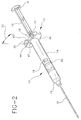
- Figure 2 illustrates the backstop 10 in perspective as mounted to a medical delivery device such as a syringe 12.
- syringe 12 generally includes a syringe barrel 14 adapted to contain a medicament therein, with the barrel 14 featuring a distal end 15 adapted in a conventional manner for attachment or mating with the piercing element 17 as previously described.
- distal end 15 could be formed as a male luer connector.
- a relatively open proximal end 19 is formed at the opposing end of the syringe barrel, through which a plunger 16 is inserted.
- the plunger 16 mates with a stopper element 20 disposed in fluid-tight engagement with the interior of syringe barrel 14.
- the plunger 16 which generally is provided separate from the stopper 20, may mate with stopper 16 via a screw-type or other arrangement, as the skilled artisan will appreciate.
- the plunger 16 typically includes a finger rest 18 provided at its proximal end for manipulation by a user; likewise, syringe 12 typically also includes a flange 22 adjacent the open proximal end 19, forming a type of finger rest permitting the user to manipulate the syringe 12 during use.
- the flange 22 may take various shapes such as round (Figure 12b) or, as oftentimes seen, a type of modified rounded, which includes a pair of straight sides 50 ( Figure 12b), as the skilled artisan will appreciate.
- backstop 10 in accordance with the present invention is configured for mating with a syringe 12 via the flange element 22. It will be appreciated and understood by those skilled in the art, however, that the backstop 10 in accordance with the invention may be applied to other medical delivery devices, where it is desired to avert inadvertent withdrawal of an element such as stopper 20.
- one embodiment of backstop 10 in accordance with the invention features a bottom plate 30 and a top plate 32, spaced apart from one another so as to create therebetween a pocket-type enclosure 31 which is dimensioned and configured to accommodate therein flange 22 of the syringe.
- bottom plate 30 may be eliminated in favor of a top plate extension portion 30a (see Figures 19 and 20) which locks about flange 22.
- the enclosure 31 includes a frontal opening 35 through which flange 32 enters enclosure 31.
- frontal opening 35 is configured and dimensioned in a manner to permit the mounting of backstop 10 over flange 22 regardless of the angle of approach or orientation between flange 22 and backstop 10.
- Side walls 33 may serve to connect top and bottom plates 32 and 30, respectively, and help define enclosure 31.
- backstop 10 may be formed in any one of conventional manners such as injection molding. It may be formed from appropriate medical grade plastics, hard rubber materials, glass, metals or the like.
- top and bottom plates 32 and 30 are herein depicted as relatively flat, if desired, either one or both of them can be formed with a concave shape (see Fig. 11) such that the plates are free to flex towards and away from enclosure 31. In this manner, either or both of the top and bottom plates 32, 30 may flex as the backstop 10 is placed about flange 22, thereby accounting for any tolerance deviations, inconsistencies of shape or surface, or other difficulties displayed by the flange 22. Also, in this manner, backstop 10 may exert a more positive holding action onto flange 22, should such increased force be necessary or desirable. While not depicted in the Figures, the skilled artisan will also appreciate that the device in general may be dimensioned and configured so that the plates may assume a convex shape to achieve the same purpose.
- Bottom plate aperture 34 is generally configured and dimensioned for form fitting contact with the exterior surface of syringe barrel 14, while top plate aperture 36 is generally dimensioned to accommodate insertion of syringe plunger 16 therethrough.
- the aperture 36 itself and/or the structure associated therewith forms a passageway through plate 32 that is somewhat smaller than the internal diameter defined by open distal end 19 of syringe barrel 14.
- bottom aperture 34 is formed in a relatively arcuate manner so as to conform to the relatively cylindrical outside surface of syringe barrel 14.
- the shape of the aperture is not necessarily so limited and, as can be appreciated, can be configured to accommodate any shape taken by syringe barrel 14, such as ovoid, square, etc.
- each of the respective plate apertures 34, 36 may be provided with lead openings formed or otherwise cut through the plates.
- bottom plate 30 features a lead opening 42, which is connected to aperture 34 via a pair of transition edges 44. Transition points 45 define the parameters demarcating bottom aperture 34 from transition edges 44.
- top plate opening 40 is connected to top plate aperture 36 via a pair of top plate transition edges 46, whose demarcation from top aperture 36 is noted by transition points 47.
- both of the lead openings 40, 42 are themselves encompassed by frontal opening 35 of the device.
- bottom aperture 34 can be formed, for instance, in an arcuate manner extending at least equal to if not greater than 180°, such that the chordal distance between transition points 45 is formed least equal to, if not slightly less than, the outside diameter of syringe barrel 14. In this manner, when backstop 10 is fitted to the syringe, the syringe barrel 14 may be urged past the transition points 45.
- the aperture 34 can expand slightly to accommodate the syringe barrel 14, such that when the backstop 10 is in place respective of flange 22, transition edges 45 will re-contract about the syringe barrel 14, causing aperture 34 to exert a positive holding action therewith.
- the width of bottom opening 42 can be configured slightly greater than the width of top opening 40, in a manner that the bottom opening 42 may readily guide the user 42 into easily placing backstop 10 around the syringe barrel 14 for placement about flange 22.
- top plate 32 and, in particular, top aperture 36 is structured both to prevent inadvertent withdrawal of stopper 20 from the open distal end 19 of the syringe barrel 14, as well as to enhance secure locking retention of backstop 10 relative to syringe barrel 14. It also permits plunger rod 16 to be inserted through aperture 36 when the backstop 10 is already placed on the flange, or allows backstop 10 to be placed on flange 22 when the plunger rod is already in place. As previously noted, the diameter of aperture 36 is formed large enough to permit insertion of plunger rod 16 therethrough.
- plunger rod 16 is normally formed from a plurality of vanes 16a, defining a minimum width "X" and a maximum width " ⁇ ".
- the chordal distance between transition points 47 may be formed at least equal to if not slightly greater than "X" to permit rod 16 to access the aperture 36 via the opening 40.
- Top aperture 36 is formed through the width of top plate 32 in a manner to define a frusto-conical sloping wall 36a which extends about the periphery of top opening 36.
- Frusto-conical wall 36a serves to guide insertion of plunger rod 16 and, if need or desire dictate, permits insertion of stopper 20 into syringe barrel 14 through the backstop 10, if already fitted to the syringe.
- a ridge element 38 is formed about the periphery 37 of the aperture 36.
- the ridge 38 is relatively continuous, but if need or desire dictate, ridge 38 can be formed in discontinuous sections from a plurality of individual ridge elements 38.
- the ridge element 38 may take any number of configurations, but as depicted in Fig. 13, ridge element 38 extends below periphery 37 in a frusto-conical manner towards the interior of syringe barrel 14. It also further constricts the diameter of aperture 36 as defined around periphery 37. Notably, the diameter measured at periphery 37 should be formed large enough to accommodate insertion of plunger rod 16 therethrough.
- ridge element 38 can be configured to contact a portion of syringe barrel 14, either adjacent the intersection between distal end 19 and the flange 22, or as previously noted respective of Figure 13, with a portion of interior surface of syringe barrel 14 adjacent the open distal end 19.
- sloping wall 36a and the outside periphery of ridge 38 contact the interior surface of syringe barrel 14 (or, as noted above, adjacent the intersection between distal end 19 and the flange 22) so as to enhance locking retention of backstop 10 to the syringe barrel 14.
- stopper 20 is prevented from inadvertent withdrawal from syringe barrel 14, assisted in this case by engagement with the inwardly facing edge of ridge 38 if withdrawal is attempted.
- a user may insert stopper 20 into the syringe barrel 14 even if backstop 10 is in place about flange 22 if such action is desired.
- ridge 38 will make contact with stopper 20 to block any attempt to withdraw the stopper from the syringe.
- the height of ridge 38 may be formed such that a transitional area 38b is provided, at either end of aperture 36 in the vicinity adjacent top transitional edges 47.
- the height "H" (see Figure 7) of ridge 38 may extend from virtually zero at the transitional edges 47, increasing to a position of maximal, constant height 38a directly opposite openings 40, 42.
- the transition of the ridge height to a position of maximal height 38a might entail forming the position of maximal height for an arcuate section around the ridge.
- the position of maximal height 38 might entail a peak portion located at the intersection of the transitional areas 38b.
- the ridge 38 By providing a gradual transition of height "H" of the ridge from about zero adjacent the opening to a maximum height opposite the opening, the ridge 38 easily slides over the flange surface, so that backstop 10 can be readily guided for insertion over the flange 22.
- the progression may assume other shapes such as peaked triangular (wherein transitional area 38b is linear to constant height 38a), various sinusoidal cross-sections, or like variations as can be envisioned by the skilled artisan.
- ridge 38 may assume alternate configurations such as discontinuous raised dots or protrusions which gradually peak in height to a maximum value 38a.
- a rib element 52 may be formed between plates 32, 30 in the enclosure 31 of backstop 10, and adjacent the back edge of the device directly opposite openings 40, 42. While here depicted formed adjacent bottom plate 30, rib 52 can also be formed adjacent top plate 32, or formed in two parts on both of the plates 30,32.
- the rib 52 which may be injection molded along with the remainder of backstop 10, is preferably configured for surface contact with an edge or other portion of the flange 22 when backstop 10 is fully inserted relative to flange 22. For instance, for the modified, rounded flange 22 depicted in Figure 12a, rib 52 can be formed for contact with straight side 50 thereof (see Figure 15).
- rib 52 be configured so that a slight gap exists between it and flange 22 when backstop 10 is positioned onto flange 22. By providing some stabilizing contact with the edge of the flange, rib 52 serves to lessen rotation or play of backstop 10 relative to syringe 14.
- the backstop 10 in accordance with the present invention is readily flexible, permitting its assembly with a syringe 14 either in the presence or absence of the syringe plunger 16, depending upon the filling and/or assembly line chosen by the manufacturer.
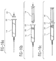
- the stopper 20 and then syringe plunger 16 is inserted relative to the syringe barrel 14 during the assembly process ( Figures 16a and b).
- the backstop 10 is inserted relative to the flange 22 (16c and d), representative of assembly either during the filling or sterilization processes, or affixation by an end user to a previously filled and sterilized syringe shipped by the manufacturer.
- frontal opening 35 provides access to enclosure 31.
- Frontal opening 35 is configured to permit the placement of backstop 10 to flange 22, irrespective of the angular orientation between the backstop 10 and the flange 22.
- backstop 10 is illustrated in numerous positions of angular orientation as it approaches flange 22 (see sub-figure 18 a).
- the backstop 10 is illustrated as fitted to flange 22, showing that it can be placed over the flange 22 regardless of angular orientation.
- backstop 10 can be rotated respective of flange 22, for instance, until rib 52 makes contact with straight side 50 (see the first illustration of Figure 18b).
- top plate extension 30a (see Figures 19-20) extending about all or a portion of the periphery of the device.
- the top plate extension 30a together with side walls 33, define with the top plate an enclosure portion 31a which locks about the flange 22, absent contact with the walls of syringe 14 as in the prior described embodiment.
- extension 30a is depicted as jutting beneath the bottom surface of flange 22, the skilled artisan will appreciate that extension 30a could be configured for contact solely with or about the peripheral edge of flange 22 to achieve locking as described above.
Abstract
Description
- The invention relates to a backstop device for a syringe, and more particularly, to a backstop device for a syringe which prevents inadvertent removal of the stopper component associated with the syringe.
- As is known in the art, syringes are medical delivery devices utilizable to administer a medicament to a patient. Syringes are normally marketed either in prefilled form, wherein a set dosage of medicament is already provided therein, or they are empty and intended to be filled from a vial or other source of medicament by an end user at the time administration of the medicament is desired.
- Syringes typically include a barrel portion adapted to retain the medicament. The distal end of the barrel is normally configured to mate with a conventional piercing element, such as a pointed needle cannula made of steel or like material or a blunt ended cannula formed of plastic, to deliver the medicament contained in the barrel. A plunger rod is inserted through the open distal end of the syringe barrel and, through its engagement with an elastomeric or rubber-like stopper element fitted in a fluid-tight manner within the interior of the barrel, a user can apply manual force to the plunger to deliver the medicament through the piercing element. A flange is also typically provided around the open distal end of the syringe barrel as a form of finger rest to facilitate a user's manipulation of the device.
- As the skilled artisan will appreciate, one problem with either pre-filled syringes or empty syringes is that the stopper element can be inadvertently dislodged from the syringe barrel, rendering the syringe itself unusable and/or the medicament therein unsterile. For instance, particularly in the case of prefilled syringes, forces exerted on the stopper during terminal sterilization procedures could cause the stopper to eject from the open distal end of the syringe, rendering the product unusable. Also, end users attempting to aspirate medicament through the piercing element into the syringe barrel could, inadvertently, exert excess force onto the plunger, causing the stopper to dislodge from the barrel. There is also the risk that for certain medicaments, such as cytotoxic drugs, that safety concerns dictate that the stopper not be dislodged from the barrel.
- Numerous attempts in the art have sought to address the aforementioned concerns. For instance, U.S. Patent No. 4,711,637 to Leigh et al. describes a syringe lock formed as a clip made from a malleable material such as sheet metal. The clip, affixed to the proximal end of the syringe, includes a protrusion jutting towards the interior portion of the barrel which serves to "bite" into the plunger so as to arrest movement thereof once a desired plunger position is achieved. In this type of device, inadvertent rotation of the plunger could cause unwanted locking, rendering the syringe unusable. Another clip-type approach is found in U.S. Patent No. 4,883,471 to Braginetz et al., wherein a spring clip is disposed around the exterior of the syringe barrel. The clip includes finger elements protruding through apertures formed in the syringe barrel. The finger elements physically arrest the stopper element once a desired plunger extension is reached.
- Alternately, structure may be incorporated as part of the syringe barrel itself to physically restrain the syringe stopper from inadvertent withdrawal. Examples of these approaches are found, inter alia, in U.S. Patent No. 4,946,441 to Laderoute and European Patent Application No. 0 409 134 to Escudero. These approaches are oftentimes uneconomical in that costly modifications will be required to molding equipment to achieve the desired structure. In addition, by employing specific, integral syringe barrel construction, the user is deprived of the ability to effect easy, intentional removal of the stopper by disabling the stopper lock structure, if such action is desired.
- PCT Application WO 94/26334 discloses, inter alia, two embodiments of a plunger lock device for a syringe. A first embodiment is of the spring clip type and includes a finger portion 61 jutting into the interior of the syringe barrel. The finger portion 61 physically arrests the stopper from inadvertent withdrawal. A second embodiment entails a disk-like addition which mounts to the flange area of the syringe. The top portion of the disk includes an aperture, aligned with the syringe barrel, that is smaller than the internal diameter of the barrel. While the smaller diameter disk aperture prevents the stopper from inadvertent withdrawal, this embodiment can only be effected where the disk is first mounted to the syringe flange and the plunger thereafter inserted through the disk aperture for attachment to the stopper. Accordingly, the disk device as taught therein is mainly intended for use where it is shipped intact with a fully assembled syringe, and most likely where affixation of the plunger lock device is part of the syringe filling, assembly and/or sterilization processes. Most syringe processing machinery, however, is not set up to accommodate manipulation of the lock device, and modifications to the production line can be costly if not difficult. For reasons of economy, and particularly where specialized filling or sterilization machinery is already in place, it would be advantageous to ship the device apart from a pre-filled or pre-assembled syringe for later affixation. Moreover, it would also be advantageous to permit affixation of the brake device as an add-on component, without having to disrupt the plunger from the stopper.
- These and related concerns are addressed by a syringe backstop device in accordance with the present invention. The device, readily applicable to either plastic or glass syringes, is preferably formed as a plate-like structure, and may be adapted to the dimensions of the syringe flange in a manner to enhance a user's grip of the device. In one embodiment, the backstop includes spaced apart top and bottom plates allowing the device to be fitted to the flange. Each plate includes respective apertures therethrough, the bottom aperture preferably conforming to the exterior dimensions of the syringe barrel, while the top aperture includes a ridge element adapted to snugly fit with the interior diameter of the syringe barrel. In one configuration, the top aperture is formed through the top plate in a frusto-conical configuration, with the ridge element disposed at the bottom of a lead wall defined by the frusto-conically shaped top aperture. The ridge acts both to enhance retention of the device with the syringe and to serve as a physical barrier preventing the stopper from inadvertent withdrawal from the syringe barrel. Each of the plate apertures includes a lead opening through its respective plate to permit the mounting of the device to the syringe flange, regardless of the presence or absence of the plunger. The openings are further dimensioned to accommodate flanges of varying shapes irrespective of the angular orientation of the openings with respect to the flange. The lead openings include transition edges extending from the lead opening to the respective aperture. The bottom lead opening may be formed to guide the user in placing the device onto the syringe. The bottom transition edges may be formed with a wider rake respective of top transition edges for the same purpose. A rib element, preferably located adjacent either of the top or bottom plates, or both, and preferably opposite the lead openings, may be configured for engagement with a portion of the flange so as to minimize inadvertent rotation or play of the device.
- The invention will now be described in greater detail by way of reference to the appended drawings, wherein:
- Figure 1 depicts, in bottom perspective view, one embodiment of a backstop device in accordance with the present invention;
- Figure 2 depicts the backstop device of the present invention mounted to a conventional syringe;
- Figure 3 is a bottom view of the embodiment depicted in Figure 1;
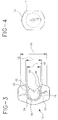
- Figure 4 is a top view illustrating a conventional syringe flange;
- Figure 5 depicts a top view of the backstop illustrated in Figure 1;
- Figure 6 is a top view illustrating a conventional syringe plunger;
- Figure 7 is a side cut-away view of the embodiment of the backstop illustrated in Figure 1;
- Figure 8 is a partial cut-away, frontal view of the backstop illustrated in Figure 1;
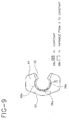
- Figure 9 is a second bottom view of the embodiment illustrated in Figure 1, depicting one formation of the ridge;
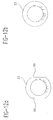
- Figure 9a is a graphical illustration of the progression of the height of the ridge as seen in Figure 9;
- Figure 9b is a graphical illustration of an alternate progression of the height of the ridge;
- Figure 10 is a top perspective view of one embodiment of the backstop in accordance with the present invention;
- Figure 11 depicts one embodiment of the backstop device in accordance with the present invention wherein the top and bottom plates are formed with concave surfaces;
- Figure 12 (12a and 12b) depicts two possible shapes of flanges utilized on syringes;
- Figure 13 is a frontal cross-sectional view depicting the backstop mounted to a syringe and flange;
- Figure 13a depicts a second frontal cross-sectional view depicting the backstop mounted to a syringe and flange;
- Figure 14 is a partial rear view of the backstop illustrating placement of the rib relative to the top and bottom plates;
- Figure 15 is a top view of the backstop mounted to the flange of a syringe and illustrating the positioning of the rib relative to the flange.
- Figure 16 (16a to 16d) illustrates placement of the backstop relative to the flange after the plunger is assembled onto the syringe;
- Figure 17 (17a to 17d) depicts placement of the backstop relative to the flange before assembly of the plunger onto the syringe;
- Figure 18 depicts placement of the backstop relative to the flange at differing angles of orientation therebetween;
- Figure 19 is a bottom view of an alternative embodiment of the backstop device of the invention; and
- Figure 20 is a cross-sectional view illustrating the embodiment of Figure 19 mounted to a syringe.
- Turning now to the drawings, wherein like numerals denote like components, Figures 1 and 3-15 depict one embodiment of a
backstop 10 in accordance with the present invention. Figure 2 illustrates thebackstop 10 in perspective as mounted to a medical delivery device such as asyringe 12. As depicted,syringe 12 generally includes asyringe barrel 14 adapted to contain a medicament therein, with thebarrel 14 featuring adistal end 15 adapted in a conventional manner for attachment or mating with the piercingelement 17 as previously described. For instance,distal end 15 could be formed as a male luer connector. A relatively openproximal end 19 is formed at the opposing end of the syringe barrel, through which aplunger 16 is inserted. Theplunger 16 mates with astopper element 20 disposed in fluid-tight engagement with the interior ofsyringe barrel 14. Theplunger 16, which generally is provided separate from thestopper 20, may mate withstopper 16 via a screw-type or other arrangement, as the skilled artisan will appreciate. Theplunger 16 typically includes afinger rest 18 provided at its proximal end for manipulation by a user; likewise,syringe 12 typically also includes aflange 22 adjacent the openproximal end 19, forming a type of finger rest permitting the user to manipulate thesyringe 12 during use. As depicted in Figure 12, theflange 22 may take various shapes such as round (Figure 12b) or, as oftentimes seen, a type of modified rounded, which includes a pair of straight sides 50 (Figure 12b), as the skilled artisan will appreciate. - As depicted herein, backstop 10 in accordance with the present invention is configured for mating with a
syringe 12 via theflange element 22. It will be appreciated and understood by those skilled in the art, however, that thebackstop 10 in accordance with the invention may be applied to other medical delivery devices, where it is desired to avert inadvertent withdrawal of an element such asstopper 20. - Turning now more particularly to Figures 1 through 15, one embodiment of
backstop 10 in accordance with the invention features abottom plate 30 and atop plate 32, spaced apart from one another so as to create therebetween a pocket-type enclosure 31 which is dimensioned and configured to accommodate thereinflange 22 of the syringe. As will be explained hereinafter, if desired,bottom plate 30 may be eliminated in favor of a topplate extension portion 30a (see Figures 19 and 20) which locks aboutflange 22. - The
enclosure 31 includes afrontal opening 35 through whichflange 32 entersenclosure 31. As depicted and more fully explained with reference to Figure 18,frontal opening 35 is configured and dimensioned in a manner to permit the mounting ofbackstop 10 overflange 22 regardless of the angle of approach or orientation betweenflange 22 andbackstop 10.Side walls 33 may serve to connect top andbottom plates enclosure 31. It will be appreciated and understood by those skilled in the art that backstop 10 may be formed in any one of conventional manners such as injection molding. It may be formed from appropriate medical grade plastics, hard rubber materials, glass, metals or the like. - While the top and
bottom plates enclosure 31. In this manner, either or both of the top andbottom plates backstop 10 is placed aboutflange 22, thereby accounting for any tolerance deviations, inconsistencies of shape or surface, or other difficulties displayed by theflange 22. Also, in this manner, backstop 10 may exert a more positive holding action ontoflange 22, should such increased force be necessary or desirable. While not depicted in the Figures, the skilled artisan will also appreciate that the device in general may be dimensioned and configured so that the plates may assume a convex shape to achieve the same purpose. - An aperture is provided in each of top and
bottom plates Bottom plate aperture 34 is generally configured and dimensioned for form fitting contact with the exterior surface ofsyringe barrel 14, whiletop plate aperture 36 is generally dimensioned to accommodate insertion ofsyringe plunger 16 therethrough. As will be explained in greater detail hereinbelow, theaperture 36 itself and/or the structure associated therewith forms a passageway throughplate 32 that is somewhat smaller than the internal diameter defined by opendistal end 19 ofsyringe barrel 14. As herein shown,bottom aperture 34 is formed in a relatively arcuate manner so as to conform to the relatively cylindrical outside surface ofsyringe barrel 14. However, the shape of the aperture is not necessarily so limited and, as can be appreciated, can be configured to accommodate any shape taken bysyringe barrel 14, such as ovoid, square, etc. - Both to permit insertion of
backstop 10 about theflange 22 and to permit the insertion of the backstop regardless of the presence or absence ofplunger 16, each of therespective plate apertures bottom plate 30 features alead opening 42, which is connected toaperture 34 via a pair of transition edges 44. Transition points 45 define the parameters demarcatingbottom aperture 34 from transition edges 44. Likewise, top plate opening 40 is connected totop plate aperture 36 via a pair of top plate transition edges 46, whose demarcation fromtop aperture 36 is noted bytransition points 47. As will be seen the figures, both of thelead openings frontal opening 35 of the device. - As best seen in Figures 3 through 6, where
syringe barrel 14 is relatively cylindrical,bottom aperture 34 can be formed, for instance, in an arcuate manner extending at least equal to if not greater than 180°, such that the chordal distance betweentransition points 45 is formed least equal to, if not slightly less than, the outside diameter ofsyringe barrel 14. In this manner, whenbackstop 10 is fitted to the syringe, thesyringe barrel 14 may be urged past the transition points 45. Theaperture 34 can expand slightly to accommodate thesyringe barrel 14, such that when thebackstop 10 is in place respective offlange 22, transition edges 45 will re-contract about thesyringe barrel 14, causingaperture 34 to exert a positive holding action therewith. As also will be seen in the Figures, the width ofbottom opening 42 can be configured slightly greater than the width oftop opening 40, in a manner that thebottom opening 42 may readily guide theuser 42 into easily placingbackstop 10 around thesyringe barrel 14 for placement aboutflange 22. - Turning now more particularly to Figures 1, 7, 9 and 10,
top plate 32 and, in particular,top aperture 36 is structured both to prevent inadvertent withdrawal ofstopper 20 from the opendistal end 19 of thesyringe barrel 14, as well as to enhance secure locking retention ofbackstop 10 relative tosyringe barrel 14. It also permitsplunger rod 16 to be inserted throughaperture 36 when thebackstop 10 is already placed on the flange, or allowsbackstop 10 to be placed onflange 22 when the plunger rod is already in place. As previously noted, the diameter ofaperture 36 is formed large enough to permit insertion ofplunger rod 16 therethrough. As seen in Figures 5 and 6,plunger rod 16 is normally formed from a plurality ofvanes 16a, defining a minimum width "X" and a maximum width "φ". The chordal distance betweentransition points 47 may be formed at least equal to if not slightly greater than "X" to permitrod 16 to access theaperture 36 via theopening 40. -
Top aperture 36 is formed through the width oftop plate 32 in a manner to define a frusto-conicalsloping wall 36a which extends about the periphery oftop opening 36. Frusto-conical wall 36a serves to guide insertion ofplunger rod 16 and, if need or desire dictate, permits insertion ofstopper 20 intosyringe barrel 14 through thebackstop 10, if already fitted to the syringe. - A
ridge element 38 is formed about theperiphery 37 of theaperture 36. As herein depicted, theridge 38 is relatively continuous, but if need or desire dictate,ridge 38 can be formed in discontinuous sections from a plurality ofindividual ridge elements 38. Theridge element 38 may take any number of configurations, but as depicted in Fig. 13,ridge element 38 extends belowperiphery 37 in a frusto-conical manner towards the interior ofsyringe barrel 14. It also further constricts the diameter ofaperture 36 as defined aroundperiphery 37. Notably, the diameter measured atperiphery 37 should be formed large enough to accommodate insertion ofplunger rod 16 therethrough. - If desired, as depicted in Figure 13a,
ridge element 38 can be configured to contact a portion ofsyringe barrel 14, either adjacent the intersection betweendistal end 19 and theflange 22, or as previously noted respective of Figure 13, with a portion of interior surface ofsyringe barrel 14 adjacent the opendistal end 19. Thus, oncebackstop device 10 is fully fitted aboutflange 22, slopingwall 36a and the outside periphery ofridge 38 contact the interior surface of syringe barrel 14 (or, as noted above, adjacent the intersection betweendistal end 19 and the flange 22) so as to enhance locking retention ofbackstop 10 to thesyringe barrel 14. Moreover, owing to thesmaller diameter aperture 36 vis-à-vis the internal diameter ofsyringe barrel 14,stopper 20 is prevented from inadvertent withdrawal fromsyringe barrel 14, assisted in this case by engagement with the inwardly facing edge ofridge 38 if withdrawal is attempted. Note that by providing the frusto-conical wall 36a about the periphery ofaperture 36, a user may insertstopper 20 into thesyringe barrel 14 even ifbackstop 10 is in place aboutflange 22 if such action is desired. However,ridge 38 will make contact withstopper 20 to block any attempt to withdraw the stopper from the syringe. - To effect easy introduction of
backstop 10 overflange 22, it will be noted (referring to Figure 9) that the height ofridge 38 may be formed such that atransitional area 38b is provided, at either end ofaperture 36 in the vicinity adjacent toptransitional edges 47. Thus, the height "H" (see Figure 7) ofridge 38 may extend from virtually zero at thetransitional edges 47, increasing to a position of maximal,constant height 38a directlyopposite openings maximal height 38a might entail forming the position of maximal height for an arcuate section around the ridge. Alternately, as seen in Figure 9b, the position ofmaximal height 38 might entail a peak portion located at the intersection of thetransitional areas 38b. By providing a gradual transition of height "H" of the ridge from about zero adjacent the opening to a maximum height opposite the opening, theridge 38 easily slides over the flange surface, so thatbackstop 10 can be readily guided for insertion over theflange 22. Alternatively, the progression may assume other shapes such as peaked triangular (whereintransitional area 38b is linear toconstant height 38a), various sinusoidal cross-sections, or like variations as can be envisioned by the skilled artisan. Likewise,ridge 38 may assume alternate configurations such as discontinuous raised dots or protrusions which gradually peak in height to amaximum value 38a. Thus, whenmaximal portion 38a ofridge 38 contacts the opendistal end 19 of the syringe, additional force by a user placing thebackstop 10 over the flange causes theportion 38a to be thrust overflange 22 into contact with the interior surface ofsyringe barrel 14 adjacent opendistal end 19, thereby providing added retention ofbackstop 10 relative to thesyringe 14 as previously described. - As seen in Figures 7, 9, 14, and 15, a
rib element 52 may be formed betweenplates enclosure 31 ofbackstop 10, and adjacent the back edge of the device directlyopposite openings adjacent bottom plate 30,rib 52 can also be formed adjacenttop plate 32, or formed in two parts on both of theplates rib 52, which may be injection molded along with the remainder ofbackstop 10, is preferably configured for surface contact with an edge or other portion of theflange 22 whenbackstop 10 is fully inserted relative toflange 22. For instance, for the modified,rounded flange 22 depicted in Figure 12a,rib 52 can be formed for contact withstraight side 50 thereof (see Figure 15). To avoid interference between the rib and the flange and to otherwise allow some rotation for backstop 10 (for instance, wherebackstop 10 is inserted at an angle respective of flange 22), it is preferable thatrib 52 be configured so that a slight gap exists between it andflange 22 whenbackstop 10 is positioned ontoflange 22. By providing some stabilizing contact with the edge of the flange,rib 52 serves to lessen rotation or play ofbackstop 10 relative tosyringe 14. - Thus, the
backstop 10 in accordance with the present invention is readily flexible, permitting its assembly with asyringe 14 either in the presence or absence of thesyringe plunger 16, depending upon the filling and/or assembly line chosen by the manufacturer. For instance, referring to Figure 16, as depicted in sub-figures 16a-d, thestopper 20 and thensyringe plunger 16 is inserted relative to thesyringe barrel 14 during the assembly process (Figures 16a and b). Thereafter, thebackstop 10 is inserted relative to the flange 22 (16c and d), representative of assembly either during the filling or sterilization processes, or affixation by an end user to a previously filled and sterilized syringe shipped by the manufacturer. By contrast, in Figure 17, thebackstop 10 is fitted shortly afterstopper 20 is inserted into the syringe barrel 14 (see Figures 17a and b), with theplunger rod 16 thereafter mated betweenstopper 20 whenbackstop 10 is already in place on the device (see Figures 17c and d). - As previously noted,
frontal opening 35 provides access toenclosure 31.Frontal opening 35 is configured to permit the placement ofbackstop 10 toflange 22, irrespective of the angular orientation between thebackstop 10 and theflange 22. Referring to Figure 18, backstop 10 is illustrated in numerous positions of angular orientation as it approaches flange 22 (see sub-figure 18 a). Likewise, in sub-figure 18b, thebackstop 10 is illustrated as fitted toflange 22, showing that it can be placed over theflange 22 regardless of angular orientation. For aflange 22 of modified, rounded configuration as illustrated in Figure 12a, backstop 10 can be rotated respective offlange 22, for instance, untilrib 52 makes contact with straight side 50 (see the first illustration of Figure 18b). By providing such structure, backstop 10 is readily manipulable by a user ontoflange 22, contributing to ease of use and placement. - While the embodiment principally depicted in Figures 1-15 is shown with both
top plate 32 andbottom plate 30, it will be realized and understood by the skilled artisan that, if desired,bottom plate 30 can be eliminated in favor of atop plate extension 30a (see Figures 19-20) extending about all or a portion of the periphery of the device. Thetop plate extension 30a, together withside walls 33, define with the top plate anenclosure portion 31a which locks about theflange 22, absent contact with the walls ofsyringe 14 as in the prior described embodiment. While theextension 30a is depicted as jutting beneath the bottom surface offlange 22, the skilled artisan will appreciate thatextension 30a could be configured for contact solely with or about the peripheral edge offlange 22 to achieve locking as described above. - It will be appreciated and understood by those skilled in the art that further and additional forms of the invention may be devised without departing from the spirit and scope of the appended claims, the invention not being limited to the specific embodiments shown.
Claims (10)
- A device for preventing inadvertent removal of a stopper from a syringe, said syringe including a barrel having an open proximal end and a flange adjacent said open proximal end, comprising:
a backstop attachable to the flange, the backstop comprising a top plate and a bottom plate, the plates oriented to capture the flange therebetween;
said bottom plate defining an aperture therethrough adapted to engage the outside surface of said syringe barrel, said top plate defining an aperture therethrough in communication with the open proximal end of the syringe barrel;
a ridge on said top plate adjacent the top plate aperture, said ridge adapted to engage a portion of the syringe barrel adjacent the open proximal end, said ridge dimensioned to prevent withdrawal of the stopper from the syringe barrel;
a lead opening formed in each of said top and bottom plates, each of said lead openings connected to a respective aperture formed in the plates, said lead openings oriented to permit insertion of the flange between said plates. - The device of claim 1, wherein at least one of said top plate or bottom plate is concave.
- The device of claim 1, wherein at least one of said top plate or bottom plate is flat.
- The device of claim 1, further comprising a rib formed adjacent an edge portion of said top or bottom plates, said rib oriented for contact with said syringe flange to reduce unwanted rotation of said backstop relative to said syringe.
- The device of claim 1, wherein said ridge comprises a protrusion formed about a portion of the periphery of said top disk aperture, said protrusion engageable with the open distal end of the syringe.
- The device of claim 1, wherein said ridge is continuous.
- The device of claim 1, wherein said ridge includes a height, the height of said ridge formed progressively higher as said ridge progresses away from the lead opening of said top plate.
- The device of claim 11, wherein the height of said ridge includes a position of maximal height opposite said lead opening.
- The device of claim 12, wherein said position of maximal height extends for an arcuate distance about said ridge.
- The device of claim 1, wherein said top plate aperture defines a substantially frusto-conically shaped lead wall oriented towards the open proximal end of the syringe barrel, the ridge disposed at a bottom portion of said lead wall.
Applications Claiming Priority (2)
| Application Number | Priority Date | Filing Date | Title |
|---|---|---|---|
| US426519 | 1995-04-21 | ||
| US08/426,519 US5667495A (en) | 1995-04-21 | 1995-04-21 | Backstop device for a syringe |
Publications (2)
| Publication Number | Publication Date |
|---|---|
| EP0738517A1 true EP0738517A1 (en) | 1996-10-23 |
| EP0738517B1 EP0738517B1 (en) | 2002-06-05 |
Family
ID=23691128
Family Applications (1)
| Application Number | Title | Priority Date | Filing Date |
|---|---|---|---|
| EP96200839A Expired - Lifetime EP0738517B1 (en) | 1995-04-21 | 1996-03-27 | Backstop device for a syringe preventing inadvertent withdrawal of a stopper |
Country Status (6)
| Country | Link |
|---|---|
| US (1) | US5667495A (en) |
| EP (1) | EP0738517B1 (en) |
| JP (1) | JP2814983B2 (en) |
| CA (1) | CA2173669C (en) |
| DE (1) | DE69621515T2 (en) |
| ES (1) | ES2174021T3 (en) |
Cited By (8)
| Publication number | Priority date | Publication date | Assignee | Title |
|---|---|---|---|---|
| DE19613035A1 (en) * | 1996-03-19 | 1997-09-25 | Ferring Arzneimittel Gmbh | Hypodermic syringe finger grip |
| DE19936294A1 (en) * | 1999-08-02 | 2001-02-15 | Hans Mueller | syringe |
| EP1134001A1 (en) | 2000-03-15 | 2001-09-19 | Schott Glas | Syringe for medical use |
| WO2012041946A1 (en) * | 2010-10-01 | 2012-04-05 | Bracco Imaging Spa | Finger-grip device for medical syringe or cartridge |
| WO2016084004A1 (en) * | 2014-11-26 | 2016-06-02 | Fisher Clinical Services GmbH | Syringe assembly with plunger rod backstop and method of use |
| WO2017039786A1 (en) * | 2015-09-02 | 2017-03-09 | Amgen Inc. | Syringe assembly adapter for a syringe |
| EP3536310B1 (en) | 2012-06-01 | 2021-04-28 | Novartis AG | Syringe |
| EP3381444B1 (en) | 2012-07-03 | 2021-05-19 | Novartis AG | Syringe |
Families Citing this family (51)
| Publication number | Priority date | Publication date | Assignee | Title |
|---|---|---|---|---|
| AU9202398A (en) | 1997-09-29 | 1999-04-23 | Becton Dickinson & Company | Injection device and drug cartridge for preventing cross-use of the device and drug cartridge |
| USD419671S (en) * | 1998-10-27 | 2000-01-25 | Becton Dickinson And Company | Prefillable syringe |
| USD434850S (en) * | 1999-01-15 | 2000-12-05 | Bracco Research,USA | Finger grip collar for a syringe or cartridge barrel |
| JP2011025068A (en) * | 1999-02-22 | 2011-02-10 | Chugai Pharmaceut Co Ltd | Pre-filled syringe protein solution product |
| DE29912965U1 (en) * | 1999-07-24 | 1999-09-16 | Hoelzle Dieter Tech Projekte | Injection device |
| JP4593714B2 (en) * | 2000-02-10 | 2010-12-08 | 株式会社根本杏林堂 | Syringe outer cylinder, syringe holder, syringe piston and piston holder |
| AU2001236018A1 (en) * | 2000-03-02 | 2001-09-12 | Chugai Seiyaku Kabushiki Kaisha | Prefilled syringe assembly |
| JP4607375B2 (en) * | 2001-06-06 | 2011-01-05 | 株式会社アルテ | Auxiliary grip of syringe for container |
| JP2004008639A (en) * | 2002-06-10 | 2004-01-15 | Nipro Corp | Stopper for preventing gasket from coming off for pre-filled syringe |
| US7678333B2 (en) * | 2003-01-22 | 2010-03-16 | Duoject Medical Systems Inc. | Fluid transfer assembly for pharmaceutical delivery system and method for using same |
| ES2344896T3 (en) * | 2003-01-22 | 2010-09-09 | Duoject Medical Systems Inc | PHARMACEUTICAL PRODUCT SUPPLY SYSTEMS. |
| DE10326706A1 (en) | 2003-06-04 | 2005-01-05 | Schott Ag | Syringe, in particular for medical applications, and method for producing such |
| JP4460278B2 (en) * | 2003-12-17 | 2010-05-12 | 株式会社大協精工 | Seal plug for syringe and prefilled syringe |
| DE102004009919B4 (en) | 2004-02-20 | 2007-02-08 | Schott Ag | Syringe, especially for medical applications |
| DE102004009918B4 (en) * | 2004-02-20 | 2007-03-01 | Schott Ag | Arrangement for storing, transporting and applying a preferably medical liquid |
| US20070073226A1 (en) * | 2005-09-23 | 2007-03-29 | John Polidoro | Syringe |
| JP4568201B2 (en) * | 2005-09-28 | 2010-10-27 | 村瀬硝子株式会社 | Finger pad |
| US20190030253A1 (en) * | 2007-04-20 | 2019-01-31 | Synergize Co. | Ergonomic syringe |
| US20090105689A1 (en) * | 2007-10-22 | 2009-04-23 | Mitchum Mark V | Removable push-off tab for IV catheter |
| CN102716532A (en) * | 2008-01-15 | 2012-10-10 | 西部制药服务公司 | Collet mechanism and method of molding cannula to a syringe barrel |
| US8721603B2 (en) | 2008-01-15 | 2014-05-13 | West Pharmaceutical Services, Inc. | Syringe with co-molded hub and cannula |
| JP5314687B2 (en) | 2008-06-17 | 2013-10-16 | 電気化学工業株式会社 | Syringe |
| KR101011770B1 (en) | 2008-12-10 | 2011-02-07 | 이재수 | a storage case with cylinder-shaped |
| WO2011007194A1 (en) | 2009-07-15 | 2011-01-20 | Becton Dickinson France | Tray for positioning elongated objects, in particular syringe bodies or syringes |
| WO2011015896A1 (en) | 2009-08-07 | 2011-02-10 | Becton Dickinson France | Tray for positioning elongated objects, in particular syringe bodies or syringes |
| US20110046559A1 (en) * | 2009-08-21 | 2011-02-24 | Becton Dickinson France S.A.S. | Syringe Assembly Having a Flexible or Slidable Flange |
| JP5457846B2 (en) * | 2010-01-14 | 2014-04-02 | 医療法人セレス | Chemical level adjuster |
| USD699348S1 (en) * | 2010-01-27 | 2014-02-11 | Orlando Morejon | Handle |
| GB201004102D0 (en) | 2010-03-12 | 2010-04-28 | Liversidge Barry P | Syringe barrels and handling systems |
| US8920385B2 (en) | 2010-05-05 | 2014-12-30 | Safety Syringes, Inc. | Extended finger flange for syringe systems |
| US20130018325A1 (en) * | 2011-07-11 | 2013-01-17 | Bristol-Myers Squibb Company | Flange extender for use with an injection device and method of assembly |
| USD693002S1 (en) | 2011-09-21 | 2013-11-05 | West Pharmaceutical Services, Inc. | Hub for medical container |
| USD689188S1 (en) | 2012-07-19 | 2013-09-03 | West Pharmaceutical Services, Inc. | Syringe plunger rod |
| US9227019B2 (en) | 2012-08-29 | 2016-01-05 | Amgen Inc. | Pre-filled syringe identification tag |
| JP6305027B2 (en) * | 2013-11-19 | 2018-04-04 | 株式会社トップ | Syringe aids |
| DE102014006323A1 (en) * | 2014-04-30 | 2015-11-05 | Gerresheimer Regensburg Gmbh | Pre-filled syringe with reuse protection |
| US9474864B2 (en) | 2014-12-15 | 2016-10-25 | Brell Medical Innovations, LLC | Safety syringe and methods for administration of a medicament dose by subject weight |
| USD812223S1 (en) | 2015-05-18 | 2018-03-06 | West Pharmaceutical Services, Inc. | Finger flange |
| USD790691S1 (en) | 2015-07-28 | 2017-06-27 | West Pharmaceutical Services, Inc. | Finger flange |
| AU2017246114B2 (en) * | 2016-04-08 | 2022-03-17 | Allergan, Inc. | Aspiration and injection device |
| JP1577607S (en) * | 2016-09-30 | 2017-05-29 | ||
| US10537683B2 (en) | 2016-11-03 | 2020-01-21 | Johnson & Johnson Surgical Vision, Inc. | Syringe finger grip |
| CA3067225A1 (en) * | 2017-06-16 | 2018-12-20 | Credence Medsystems, Inc. | System and method for safety syringe |
| US20190046024A1 (en) | 2017-08-10 | 2019-02-14 | Ethicon, Inc. | Volume expanders for endoscopes |
| US10814027B2 (en) | 2017-12-07 | 2020-10-27 | Asp Global Manufacturing Gmbh | Sterilization-assistance device |
| US10967084B2 (en) | 2017-12-15 | 2021-04-06 | Asp Global Manufacturing Gmbh | Flow restrictor |
| WO2020102444A1 (en) | 2018-11-13 | 2020-05-22 | Credence Medsystems, Inc. | System and method for microdose injection |
| EP3821925B1 (en) * | 2019-09-18 | 2024-03-20 | KAISHA PACKAGING Private Ltd. | Device for locking a plunger rod of a syringe after use and preventing re-use of the syringe, and syringe assembly |
| EP4168067A1 (en) | 2020-06-17 | 2023-04-26 | Credence Medsystems, Inc. | System and method for microdose injection |
| USD948714S1 (en) | 2020-06-22 | 2022-04-12 | KAISHA PACKAGING Private Ltd. | Syringe plunger lock |
| WO2024008948A1 (en) * | 2022-07-07 | 2024-01-11 | Terumo Europe Nv | Finger grip |
Citations (7)
| Publication number | Priority date | Publication date | Assignee | Title |
|---|---|---|---|---|
| FR360751A (en) * | 1905-12-21 | 1906-05-03 | Herman Adolphe Wulfing Luer | Aseptic syringe |
| DE3106988A1 (en) * | 1980-07-26 | 1982-08-19 | Günter Dr.med. 8671 Selbitz Reitz | Hypodermic syringe |
| US4592746A (en) * | 1985-06-10 | 1986-06-03 | Sherwood Medical Company | Syringe and locking device and method of assembling same |
| US4610672A (en) * | 1985-06-10 | 1986-09-09 | Sherwood Medical Company | Syringe locking device |
| US4711637A (en) * | 1986-02-04 | 1987-12-08 | Baxter Travenol Laboratories, Inc. | Syringe lock |
| EP0471335A1 (en) * | 1990-08-14 | 1992-02-19 | Hoechst Aktiengesellschaft | Syringe mounting |
| WO1994026334A1 (en) * | 1993-05-06 | 1994-11-24 | Becton Dickinson And Company | Syringe for medicinal purposes |
Family Cites Families (9)
| Publication number | Priority date | Publication date | Assignee | Title |
|---|---|---|---|---|
| US3076455A (en) * | 1958-12-19 | 1963-02-05 | Robert K Mcconnaughey | Holder for hypodermic syringe cartridges |
| DE2945869A1 (en) * | 1979-11-14 | 1981-05-27 | Hans-Dieter Dr.Med. 8501 Burgthann Ebert | Medicinal blood-sampling syringe - includes locking device holding plunger against internal vacuum |
| US4643724A (en) * | 1985-12-16 | 1987-02-17 | Alcon Laboratories, Inc. | Syringe holder |
| NO870745L (en) * | 1986-02-26 | 1987-08-27 | Intelligent Medicine Inc | INDEPENDENT MATERIAL MIXING DEVICE. |
| US4946441A (en) * | 1988-07-21 | 1990-08-07 | Maurice Laderoute | Limited use hypodermic syringe |
| US4883471A (en) * | 1988-08-16 | 1989-11-28 | Braginetz Paul A | Disposable shielded medical syringe |
| ES2014802A6 (en) * | 1989-07-17 | 1990-07-16 | Sempere Escudero Philippe | A non-reusable syringe. |
| JP2533814Y2 (en) * | 1990-11-19 | 1997-04-23 | 参天製薬株式会社 | Two-component syringe |
| JP3546335B2 (en) * | 1994-06-21 | 2004-07-28 | 生化学工業株式会社 | Auxiliary tools for syringe barrels |
-
1995
- 1995-04-21 US US08/426,519 patent/US5667495A/en not_active Expired - Lifetime
-
1996
- 1996-03-27 ES ES96200839T patent/ES2174021T3/en not_active Expired - Lifetime
- 1996-03-27 DE DE69621515T patent/DE69621515T2/en not_active Expired - Lifetime
- 1996-03-27 EP EP96200839A patent/EP0738517B1/en not_active Expired - Lifetime
- 1996-04-09 CA CA002173669A patent/CA2173669C/en not_active Expired - Fee Related
- 1996-04-19 JP JP8098732A patent/JP2814983B2/en not_active Expired - Lifetime
Patent Citations (7)
| Publication number | Priority date | Publication date | Assignee | Title |
|---|---|---|---|---|
| FR360751A (en) * | 1905-12-21 | 1906-05-03 | Herman Adolphe Wulfing Luer | Aseptic syringe |
| DE3106988A1 (en) * | 1980-07-26 | 1982-08-19 | Günter Dr.med. 8671 Selbitz Reitz | Hypodermic syringe |
| US4592746A (en) * | 1985-06-10 | 1986-06-03 | Sherwood Medical Company | Syringe and locking device and method of assembling same |
| US4610672A (en) * | 1985-06-10 | 1986-09-09 | Sherwood Medical Company | Syringe locking device |
| US4711637A (en) * | 1986-02-04 | 1987-12-08 | Baxter Travenol Laboratories, Inc. | Syringe lock |
| EP0471335A1 (en) * | 1990-08-14 | 1992-02-19 | Hoechst Aktiengesellschaft | Syringe mounting |
| WO1994026334A1 (en) * | 1993-05-06 | 1994-11-24 | Becton Dickinson And Company | Syringe for medicinal purposes |
Cited By (15)
| Publication number | Priority date | Publication date | Assignee | Title |
|---|---|---|---|---|
| DE19613035A1 (en) * | 1996-03-19 | 1997-09-25 | Ferring Arzneimittel Gmbh | Hypodermic syringe finger grip |
| DE19613035B4 (en) * | 1996-03-19 | 2007-12-13 | Ferring Gmbh | System with a syringe and a handle |
| DE19936294A1 (en) * | 1999-08-02 | 2001-02-15 | Hans Mueller | syringe |
| EP1134001A1 (en) | 2000-03-15 | 2001-09-19 | Schott Glas | Syringe for medical use |
| AU2011310580C1 (en) * | 2010-10-01 | 2016-03-10 | Bracco Imaging Spa | Finger-grip device for medical syringe or cartridge |
| AU2011310580B2 (en) * | 2010-10-01 | 2014-12-11 | Bracco Imaging Spa | Finger-grip device for medical syringe or cartridge |
| WO2012041946A1 (en) * | 2010-10-01 | 2012-04-05 | Bracco Imaging Spa | Finger-grip device for medical syringe or cartridge |
| US9289555B2 (en) | 2010-10-01 | 2016-03-22 | Bracco Imaging S.P.A. | Finger-grip device for medical syringe or cartridge |
| EP3536310B1 (en) | 2012-06-01 | 2021-04-28 | Novartis AG | Syringe |
| EP3679922B1 (en) | 2012-06-01 | 2021-07-28 | Novartis AG | Syringe |
| EP3777834B1 (en) | 2012-06-01 | 2022-02-16 | Novartis AG | Syringe |
| EP3381444B1 (en) | 2012-07-03 | 2021-05-19 | Novartis AG | Syringe |
| EP3685826B1 (en) | 2012-07-03 | 2021-11-03 | Novartis AG | Syringe |
| WO2016084004A1 (en) * | 2014-11-26 | 2016-06-02 | Fisher Clinical Services GmbH | Syringe assembly with plunger rod backstop and method of use |
| WO2017039786A1 (en) * | 2015-09-02 | 2017-03-09 | Amgen Inc. | Syringe assembly adapter for a syringe |
Also Published As
| Publication number | Publication date |
|---|---|
| JPH08294533A (en) | 1996-11-12 |
| JP2814983B2 (en) | 1998-10-27 |
| US5667495A (en) | 1997-09-16 |
| ES2174021T3 (en) | 2002-11-01 |
| CA2173669A1 (en) | 1996-10-22 |
| CA2173669C (en) | 1999-05-04 |
| DE69621515T2 (en) | 2002-10-31 |
| DE69621515D1 (en) | 2002-07-11 |
| EP0738517B1 (en) | 2002-06-05 |
Similar Documents
| Publication | Publication Date | Title |
|---|---|---|
| EP0738517B1 (en) | Backstop device for a syringe preventing inadvertent withdrawal of a stopper | |
| US5700247A (en) | Backstop device for a flangeless syringe | |
| KR920000439B1 (en) | Single-use syringe having mis-use resistant features | |
| US6217550B1 (en) | Single-use syringe | |
| US5989219A (en) | Single-use syringe | |
| EP1123713B1 (en) | Single-use syringe | |
| KR920000464B1 (en) | Single-use syringe | |
| US5833669A (en) | Medicine injection syringe constructions | |
| US6361525B2 (en) | Single-use syringe | |
| AU2003298533B2 (en) | Single-use syringe | |
| US7387615B2 (en) | Single use syringe having safety shield | |
| US6193696B1 (en) | Lockable safety shield assembly for a prefillable syringe | |
| CA2451531C (en) | Syringe and needle for preventing inadvertent drug injection | |
| CA2235940A1 (en) | Tamper evident syringe design | |
| EP0649318B1 (en) | Syringe for medicinal purposes | |
| JPH06504217A (en) | plastic syringe | |
| KR20110039539A (en) | Passive reuse prevention syringe that uses a retaining ring lock | |
| EP1064039B1 (en) | Single-use syringe | |
| EP3539594B1 (en) | Automatic injection device with a dampening element | |
| MXPA01001055A (en) | Single-use syringe | |
| KR20090036567A (en) | Improved safety syringe |
Legal Events
| Date | Code | Title | Description |
|---|---|---|---|
| PUAI | Public reference made under article 153(3) epc to a published international application that has entered the european phase |
Free format text: ORIGINAL CODE: 0009012 |
|
| AK | Designated contracting states |
Kind code of ref document: A1 Designated state(s): BE DE ES FR IT NL SE |
|
| 17P | Request for examination filed |
Effective date: 19961125 |
|
| 17Q | First examination report despatched |
Effective date: 19990714 |
|
| GRAG | Despatch of communication of intention to grant |
Free format text: ORIGINAL CODE: EPIDOS AGRA |
|
| GRAG | Despatch of communication of intention to grant |
Free format text: ORIGINAL CODE: EPIDOS AGRA |
|
| GRAH | Despatch of communication of intention to grant a patent |
Free format text: ORIGINAL CODE: EPIDOS IGRA |
|
| GRAH | Despatch of communication of intention to grant a patent |
Free format text: ORIGINAL CODE: EPIDOS IGRA |
|
| GRAA | (expected) grant |
Free format text: ORIGINAL CODE: 0009210 |
|
| AK | Designated contracting states |
Kind code of ref document: B1 Designated state(s): BE DE ES FR IT NL SE |
|
| REF | Corresponds to: |
Ref document number: 69621515 Country of ref document: DE Date of ref document: 20020711 |
|
| ET | Fr: translation filed | ||
| REG | Reference to a national code |
Ref country code: ES Ref legal event code: FG2A Ref document number: 2174021 Country of ref document: ES Kind code of ref document: T3 |
|
| PLBE | No opposition filed within time limit |
Free format text: ORIGINAL CODE: 0009261 |
|
| STAA | Information on the status of an ep patent application or granted ep patent |
Free format text: STATUS: NO OPPOSITION FILED WITHIN TIME LIMIT |
|
| 26N | No opposition filed |
Effective date: 20030306 |
|
| REG | Reference to a national code |
Ref country code: FR Ref legal event code: PLFP Year of fee payment: 20 |
|
| PGFP | Annual fee paid to national office [announced via postgrant information from national office to epo] |
Ref country code: NL Payment date: 20150326 Year of fee payment: 20 Ref country code: DE Payment date: 20150327 Year of fee payment: 20 Ref country code: ES Payment date: 20150326 Year of fee payment: 20 Ref country code: IT Payment date: 20150324 Year of fee payment: 20 |
|
| PGFP | Annual fee paid to national office [announced via postgrant information from national office to epo] |
Ref country code: FR Payment date: 20150317 Year of fee payment: 20 Ref country code: SE Payment date: 20150327 Year of fee payment: 20 |
|
| PGFP | Annual fee paid to national office [announced via postgrant information from national office to epo] |
Ref country code: BE Payment date: 20150327 Year of fee payment: 20 |
|
| REG | Reference to a national code |
Ref country code: DE Ref legal event code: R071 Ref document number: 69621515 Country of ref document: DE |
|
| REG | Reference to a national code |
Ref country code: NL Ref legal event code: MK Effective date: 20160326 |
|
| REG | Reference to a national code |
Ref country code: SE Ref legal event code: EUG |
|
| REG | Reference to a national code |
Ref country code: ES Ref legal event code: FD2A Effective date: 20160704 |
|
| PG25 | Lapsed in a contracting state [announced via postgrant information from national office to epo] |
Ref country code: ES Free format text: LAPSE BECAUSE OF EXPIRATION OF PROTECTION Effective date: 20160328 |