EP0743872B1 - Filter well - Google Patents
Filter well Download PDFInfo
- Publication number
- EP0743872B1 EP0743872B1 EP95909191A EP95909191A EP0743872B1 EP 0743872 B1 EP0743872 B1 EP 0743872B1 EP 95909191 A EP95909191 A EP 95909191A EP 95909191 A EP95909191 A EP 95909191A EP 0743872 B1 EP0743872 B1 EP 0743872B1
- Authority
- EP
- European Patent Office
- Prior art keywords
- filter
- flow channels
- ridges
- filter well
- well according
- Prior art date
- Legal status (The legal status is an assumption and is not a legal conclusion. Google has not performed a legal analysis and makes no representation as to the accuracy of the status listed.)
- Expired - Lifetime
Links
- 238000000034 method Methods 0.000 claims abstract description 9
- 238000005530 etching Methods 0.000 claims abstract description 8
- 238000003754 machining Methods 0.000 claims abstract description 4
- 238000001914 filtration Methods 0.000 abstract description 9
- 239000007788 liquid Substances 0.000 description 14
- 229920002120 photoresistant polymer Polymers 0.000 description 8
- 229910000831 Steel Inorganic materials 0.000 description 6
- 238000004519 manufacturing process Methods 0.000 description 6
- 239000010959 steel Substances 0.000 description 6
- 238000001746 injection moulding Methods 0.000 description 5
- 239000007790 solid phase Substances 0.000 description 4
- 238000010276 construction Methods 0.000 description 3
- 239000007791 liquid phase Substances 0.000 description 2
- 238000000926 separation method Methods 0.000 description 2
- 239000000243 solution Substances 0.000 description 2
- 241000894006 Bacteria Species 0.000 description 1
- OKTJSMMVPCPJKN-UHFFFAOYSA-N Carbon Chemical compound [C] OKTJSMMVPCPJKN-UHFFFAOYSA-N 0.000 description 1
- 230000006820 DNA synthesis Effects 0.000 description 1
- 239000004952 Polyamide Substances 0.000 description 1
- 239000004743 Polypropylene Substances 0.000 description 1
- 238000005842 biochemical reaction Methods 0.000 description 1
- 229910052799 carbon Inorganic materials 0.000 description 1
- 238000005119 centrifugation Methods 0.000 description 1
- 238000004587 chromatography analysis Methods 0.000 description 1
- 230000001419 dependent effect Effects 0.000 description 1
- 238000009760 electrical discharge machining Methods 0.000 description 1
- 238000003780 insertion Methods 0.000 description 1
- 230000037431 insertion Effects 0.000 description 1
- 150000007523 nucleic acids Chemical class 0.000 description 1
- 102000039446 nucleic acids Human genes 0.000 description 1
- 108020004707 nucleic acids Proteins 0.000 description 1
- 230000002093 peripheral effect Effects 0.000 description 1
- 238000000206 photolithography Methods 0.000 description 1
- 229920002647 polyamide Polymers 0.000 description 1
- -1 polypropylene Polymers 0.000 description 1
- 229920001155 polypropylene Polymers 0.000 description 1
- 238000002360 preparation method Methods 0.000 description 1
- 230000000717 retained effect Effects 0.000 description 1
- 241001515965 unidentified phage Species 0.000 description 1
- XLYOFNOQVPJJNP-UHFFFAOYSA-N water Substances O XLYOFNOQVPJJNP-UHFFFAOYSA-N 0.000 description 1
Images


Classifications
-
- B—PERFORMING OPERATIONS; TRANSPORTING
- B29—WORKING OF PLASTICS; WORKING OF SUBSTANCES IN A PLASTIC STATE IN GENERAL
- B29C—SHAPING OR JOINING OF PLASTICS; SHAPING OF MATERIAL IN A PLASTIC STATE, NOT OTHERWISE PROVIDED FOR; AFTER-TREATMENT OF THE SHAPED PRODUCTS, e.g. REPAIRING
- B29C33/00—Moulds or cores; Details thereof or accessories therefor
- B29C33/42—Moulds or cores; Details thereof or accessories therefor characterised by the shape of the moulding surface, e.g. ribs or grooves
-
- B—PERFORMING OPERATIONS; TRANSPORTING
- B01—PHYSICAL OR CHEMICAL PROCESSES OR APPARATUS IN GENERAL
- B01D—SEPARATION
- B01D29/00—Filters with filtering elements stationary during filtration, e.g. pressure or suction filters, not covered by groups B01D24/00 - B01D27/00; Filtering elements therefor
- B01D29/01—Filters with filtering elements stationary during filtration, e.g. pressure or suction filters, not covered by groups B01D24/00 - B01D27/00; Filtering elements therefor with flat filtering elements
- B01D29/012—Making filtering elements
-
- B—PERFORMING OPERATIONS; TRANSPORTING
- B01—PHYSICAL OR CHEMICAL PROCESSES OR APPARATUS IN GENERAL
- B01D—SEPARATION
- B01D29/00—Filters with filtering elements stationary during filtration, e.g. pressure or suction filters, not covered by groups B01D24/00 - B01D27/00; Filtering elements therefor
- B01D29/01—Filters with filtering elements stationary during filtration, e.g. pressure or suction filters, not covered by groups B01D24/00 - B01D27/00; Filtering elements therefor with flat filtering elements
- B01D29/05—Filters with filtering elements stationary during filtration, e.g. pressure or suction filters, not covered by groups B01D24/00 - B01D27/00; Filtering elements therefor with flat filtering elements supported
-
- B—PERFORMING OPERATIONS; TRANSPORTING
- B01—PHYSICAL OR CHEMICAL PROCESSES OR APPARATUS IN GENERAL
- B01D—SEPARATION
- B01D29/00—Filters with filtering elements stationary during filtration, e.g. pressure or suction filters, not covered by groups B01D24/00 - B01D27/00; Filtering elements therefor
- B01D29/085—Funnel filters; Holders therefor
-
- B—PERFORMING OPERATIONS; TRANSPORTING
- B29—WORKING OF PLASTICS; WORKING OF SUBSTANCES IN A PLASTIC STATE IN GENERAL
- B29L—INDEXING SCHEME ASSOCIATED WITH SUBCLASS B29C, RELATING TO PARTICULAR ARTICLES
- B29L2031/00—Other particular articles
- B29L2031/14—Filters
-
- Y—GENERAL TAGGING OF NEW TECHNOLOGICAL DEVELOPMENTS; GENERAL TAGGING OF CROSS-SECTIONAL TECHNOLOGIES SPANNING OVER SEVERAL SECTIONS OF THE IPC; TECHNICAL SUBJECTS COVERED BY FORMER USPC CROSS-REFERENCE ART COLLECTIONS [XRACs] AND DIGESTS
- Y10—TECHNICAL SUBJECTS COVERED BY FORMER USPC
- Y10S—TECHNICAL SUBJECTS COVERED BY FORMER USPC CROSS-REFERENCE ART COLLECTIONS [XRACs] AND DIGESTS
- Y10S264/00—Plastic and nonmetallic article shaping or treating: processes
- Y10S264/48—Processes of making filters
Definitions
- the present invention relates to filter wells which are useful for the separation of a solid phase from a liquid as well as to a method for their production.
- Separation of solid phase from a solution is an ordinary action in the biotechnical laboratory and is mainly carried out either by centrifugation or by collecting the solid phase on a filter.
- Such a filtration is usually carried out in so called filter wells or filter tubes, i.e. a small tube or the like, open at both ends and containing a filter through which the liquid phase is forced by applying a vacuum on the underside of the filter or a pressure on its upper side.
- a device for carrying out biochemical reactions in microtitre plates where a solution is forced through filter wells by means of gas pressure is disclosed in our US patent 5,273,718.
- the use of a positive pressure on the upper side of the filter has, among other things, the advantage that both the solid phase and the liquid phase can be collected in a simple manner. It is further possible to use a greater pressure difference (i.e. greater than 1 bar) between the underside and the upper side of the filter.
- this filter support can be a bottom portion having a central outlet opening towards which a number of radial channels made in the support surface extend, e.g. in a star- or spoke-like manner, for example as disclosed in GB-A-1.102.497 (which, however, relates to a water conduit filter).
- a channel pattern of this kind shall, on one hand, have a sufficiently large area/volume to give an acceptable volume flow through the filter, but, on the other hand, it shall have as small volume as possible, since it is often a case of filtering and collecting very small volumes of liquid.
- the filter usually has such a porosity that it is air-proof, when the liquid has passed, and the liquid volume remaining on the underside of the filter can thus not be forced out of the filter well by gas pressure.
- the capacity of the filter is also influenced by the effective filter area, i.e. the area of the filter which is not in contact with the support surface, which means that the support surface should be minimized.
- the recess pattern in the steel surface in question of the forming tool which corresponds to the pattern of the desired support surfaces, has usually been made by means of so-called spark machining with a carbon electrode.
- spark machining with a carbon electrode.
- An example of a filter which has a support surface provided with a channel pattern having such ridge dimensions, but where these are fully satisfactory for the intended uses of the filter is described in GB-A-2.149.315.
- the EP-A-0 616 837 published 28.09.94, claiming priority date 05.03.93, describes a filter well comprising a filter between two support surfaces, which have radial flow channels and are separated by ridges having a keen edge.
- the ridges have a width of 0.2 mm to 0.05 mm, preferably not more than about 0.1 mm.
- “Width” hereby means the cross extension of the ridges at their broadest section.
- the upper parts of the ridges are rounded, in order to reduce the area of contact with the filters.
- a suitable distance between the support ridges is from about 0.4 mm to about 0.1 mm. Such short distances prevent the filter from sinking into the channels and the channels can thus be made very shallow.
- the flow channels have a depth of not more than about 0.1 mm, especially to about 0.05 mm or still less.
- the ratio between the channel surface and the ridge surface can vary within wide limits but is preferably from about 4:1 to about 1:4, particularly from about 4:1 to 1:1.
- the bottom of the flow channels should be smooth to give a small flow resistance.
- the bottom portions preferably have a surface fineness (or profile depth) of less than about 0.4 ⁇ m, especially to about 0.1 ⁇ m or still finer.
- the desired pattern in the tool for forming the support surface can be obtained by laser machining, but according to the invention it is preferably obtained by etching.
- etching the inability of etching processes to etch recesses with straight side edges is namely utilized in an advantageous manner.
- the etch thus directly gives the desired curved or rounded contour of the recess in the tool, which in turn gives a rounded upper part to the ridges in the produced support surface of the filter well.
- the advantageous smooth bottom surface of the flow channels is also achieved at the same time.
- An example of photolithographic production of a forming surface is disclosed in JP-A-62-117706.
- the filter well in Fig. 1 which is intended to allow a liquid to be forced through the filter by means of a positive pressure on the upper side, consists of a bottom portion 1 and a cylindrical portion 2, for example of polypropylene.
- the bottom portion 1 has a central outlet 3 and carries a filter 4, for example based on polyamide, within the cylindrical portion 2.
- the filter support surface la of the bottom portion 1 has a flow channel system 5 which conducts liquid which has passed through the filter 4 to the outlet 3.
- the bottom portion 1 and the cylindrical portion 2 form an integrated unit with the filter 4 fused into the wall of the filter well.
- a filter well of this kind can be produced by first injection moulding the bottom portion 1, applying the filter 4 on the bottom portion and then injection moulding the cylindrical portion 2 to the bottom portion 1. This is described more in detail in our PCT-application "Method for the manufacture of filter wells" of even date and based on the Swedish patent application 9400436-3.
- the flow channel system 5 formed in the bottom portion 2 consists of a fine pattern of liquid flow channels 6 which extend radially (or in spoke-form) to the outlet opening 3.
- the parts 8 of the surface of the bottom portion which delimit the flow channels 6, 7 and thus form support for the filter 4 will in the following be termed ridge parts or ridges.
- the small dimensions of the channels and ridges are characteristic for the flow channel system 5.
- the size of the ridges 8 is critical for the invention and the ridges shall in the part of the ridge which is in contact with the filter 4 have a width of from 0.2 mm to 0.05 mm, for example from about 0.1 mm to about 0.05 mm.
- the upper parts of the ridges 8 are rounded.
- a suitable channel width about 0.4 to 0.05 mm, e.g. 0.1 mm can be mentioned but broader or more narrow channels are of course also possible depending on the thickness and properties of the filter 4.
- a suitable channel depth herein is from about 0.1 mm and less, e.g. as little as about 0.05 mm.
- the ratio between the channel area and the ridge area can for example be from about 80:20 to about 50:50. Even if not specifically shown here it might be advantageous to have the depth of the flow channels increase gradually (stepwise or continuously) towards the outlet opening 3.
- Fig. 3 liquid flow through the filter 4 influenced by a positive pressure is shown schematically, indicated by arrows 9.
- an area 11 (which in this case becomes prism-shaped) through which the liquid does not flow and which consequently does not become active at the filtration is formed in those parts of the filter 4 which are in direct contact with the ridges 8.
- these inactive parts 11 of the filter become very small and essentially the entire filter area is active at the filtration.
- it is essential that the filter has a large active surface since there is otherwise a risk of more rapid clogging.
- the required forming surface for forming the fine channel pattern in the bottom of the filter well in a tool for forming the above described filter well can be produced by laser machining but is advantageously produced by photolithography, as described in the following with reference to Figs. 4A - 4F.
- Fig. 4A schematically illustrates the end 12 of a tool unit of steel which is to be etched to produce a desired relief pattern corresponding to the desired flow channel pattern in the bottom of the filter well.
- the finely honed (which means a profile depth of less than about 0.4 ⁇ m, preferably about 0.1 ⁇ m or less) and flat end 12 has a somewhat greater diameter than the final diameter on the finished part of the tool, indicated by broken lines 13.
- the tool end 12 is coated with a UV-curable so-called photoresist 14, as illustrated in Fig. 4B for a part of the tool end 12.
- a film 15 with the desired pattern is then contact copied on the photoresist whereby the portions corresponding to the support surfaces (the ridges 8 in Fig. 2) for the filter are black on the film, designated by reference numeral 16.
- the photoresist is cured under the transparent parts 18 of the film, while the photoresist under the black parts 16 is not exposed.
- the unexposed photoresist portions can then be washed away in a development process so that the steel end 12 of the tool gets the appearance shown in Fig. 4C with exposed steel portions 19 which correspond to the portions of the photoresist which have been washed away.
- the tool end 12 is then immersed in an etch bath whereby the exposed steel parts are etched isotropically, i.e. in all directions, while the parts which are covered by the etch resistant photoresist are not affected.
- the etching is allowed to proceed until recesses 20 having the desired depth have been obtained, as shown in Fig. 4D. Owing to the isotropic etching process the recesses 20, which will form the ridges or the "support protrusions" in the filter support surface, get a curved or rounded form, the advantages of which have been explained above.
- the gradual isotropic etching process is more clearly illustrated in Fig. 4E.
- etching When the etching is finished all remaining photoresist is removed. A part of the resulting tool end 12 with the desired pattern of recesses 20 is shown in Fig. 4F. A centre hole is then made for insertion of a forming element which will form the outlet 3 of the filter well and the outer edge is honed to the desired outer diameter 13.
- the finished tool element can then be mounted in the tool for forming the filter well.
- This tool can for example be a tool as described in our above mentioned PCT-application "Method for the manufacture of filter wells" of even date.
- FIG. 5 A part of the finished bottom portion of the filter well is shown in Fig. 5 where corresponding reference numerals as in Fig. 1 and 2 have been used.
- the filter 4 rests on ridges 8 corresponding to the recesses 20 in the steel end 12, while flow channels 6 in the filter support surface have been formed from the unetched parts between the recesses 20 in the tool end 12.
- the flow channels 6 will get a very smooth bottom which facilitates the liquid flow.
Abstract
Description
- The present invention relates to filter wells which are useful for the separation of a solid phase from a liquid as well as to a method for their production.
- Separation of solid phase from a solution is an ordinary action in the biotechnical laboratory and is mainly carried out either by centrifugation or by collecting the solid phase on a filter. As examples can be mentioned preparation of nucleic acids from bacteria, bacteriophages, DNA-synthesis, PCR-products etc. Such a filtration is usually carried out in so called filter wells or filter tubes, i.e. a small tube or the like, open at both ends and containing a filter through which the liquid phase is forced by applying a vacuum on the underside of the filter or a pressure on its upper side.
- A device for carrying out biochemical reactions in microtitre plates where a solution is forced through filter wells by means of gas pressure is disclosed in our US patent 5,273,718. In comparison with application of a vacuum, the use of a positive pressure on the upper side of the filter has, among other things, the advantage that both the solid phase and the liquid phase can be collected in a simple manner. It is further possible to use a greater pressure difference (i.e. greater than 1 bar) between the underside and the upper side of the filter.
- Depending on the mechanical properties of the filter it may be necessary, especially at greater pressure differences, that the filter rests on the surface of a support fitted to the wall of the tube. As in the case of chromatography columns this filter support can be a bottom portion having a central outlet opening towards which a number of radial channels made in the support surface extend, e.g. in a star- or spoke-like manner, for example as disclosed in GB-A-1.102.497 (which, however, relates to a water conduit filter).
- A channel pattern of this kind shall, on one hand, have a sufficiently large area/volume to give an acceptable volume flow through the filter, but, on the other hand, it shall have as small volume as possible, since it is often a case of filtering and collecting very small volumes of liquid. The filter usually has such a porosity that it is air-proof, when the liquid has passed, and the liquid volume remaining on the underside of the filter can thus not be forced out of the filter well by gas pressure.
- The capacity of the filter is also influenced by the effective filter area, i.e. the area of the filter which is not in contact with the support surface, which means that the support surface should be minimized.
- The design of the channel pattern in the support surface will thus necessarily be based on a compromise between the above mentioned desires. The filter well constructions which have been available up to now have, however, not been entirely satisfactory, neither with regard to residual liquid volume nor with regard to an efficient utilization of the filter area.
- At the production of these known constructions (generally by injection moulding) the recess pattern in the steel surface in question of the forming tool, which corresponds to the pattern of the desired support surfaces, has usually been made by means of so-called spark machining with a carbon electrode. Among other things this has meant that it has not been possible to make more narrow recesses in the tool than about 0.4 mm and thus not more narrow support ridges between adjacent flow channels in the bottom of the filter well. An example of a filter which has a support surface provided with a channel pattern having such ridge dimensions, but where these are fully satisfactory for the intended uses of the filter is described in GB-A-2.149.315.
- The EP-A-0 616 837, published 28.09.94, claiming priority date 05.03.93, describes a filter well comprising a filter between two support surfaces, which have radial flow channels and are separated by ridges having a keen edge.
- According to the present invention it has been found that a more efficient filter support surface with regard to residual liquid can be obtained if the flow channel pattern is designed more densely and with finer and more shallow channels and ridges, or ribs, in between than for the known support surface constructions. More precisely these support ridges shall, according to the invention, have a sufficiently small width for those parts which are in contact with the filter to make essentially the whole upper surface of the filter effective, i.e. filtration will be carried out over the whole filter surface.
- This can be achieved also for thin filters if the ridges have a width of 0.2 mm to 0.05 mm, preferably not more than about 0.1 mm. "Width" hereby means the cross extension of the ridges at their broadest section. Further, according to the invention, the upper parts of the ridges are rounded, in order to reduce the area of contact with the filters. With a filter support surface of this kind a very efficient utilization of the filter can be obtained even for thin filters and at the same time a very small retained liquid volume (dead volume) after the filtration, but still with an acceptable volume flow through the filter.
- A suitable distance between the support ridges is from about 0.4 mm to about 0.1 mm. Such short distances prevent the filter from sinking into the channels and the channels can thus be made very shallow. Preferably the flow channels have a depth of not more than about 0.1 mm, especially to about 0.05 mm or still less.
- The ratio between the channel surface and the ridge surface can vary within wide limits but is preferably from about 4:1 to about 1:4, particularly from about 4:1 to 1:1.
- The bottom of the flow channels should be smooth to give a small flow resistance. The bottom portions preferably have a surface fineness (or profile depth) of less than about 0.4 µm, especially to about 0.1 µm or still finer.
- The desired pattern in the tool for forming the support surface can be obtained by laser machining, but according to the invention it is preferably obtained by etching. In this latter case the inability of etching processes to etch recesses with straight side edges is namely utilized in an advantageous manner. The etch thus directly gives the desired curved or rounded contour of the recess in the tool, which in turn gives a rounded upper part to the ridges in the produced support surface of the filter well. The advantageous smooth bottom surface of the flow channels is also achieved at the same time. An example of photolithographic production of a forming surface is disclosed in JP-A-62-117706.
- The invention will in the following be described more in detail with regard to a particular, non-limiting embodiment. Reference is made to the appended drawings, where:
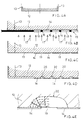
- Fig. 1 is a cross sectional view of a filter well according to the invention,
- Fig. 2 is a section (in a larger scale) along A-A in Fig. 1 where the filter has been partly cut away,
- Fig. 3 is a schematic partial cross sectional view of the filter portion of a filter well according to the invention intended to illustrate liquid flow through the filter,
- Figs. 4A - 4F show schematically different sub-steps at the production of a tool element for forming a flow channel pattern in the bottom of a filter well according to the invention, and
- Fig. 5 shows schematically a partial cross section of a peripheral filter portion in a filter well, the bottom part of the well having been formed with the tool element produced according to Figs. 4A - 4F before injection moulding of the cylindrical portion of the filter well.
-
- The filter well in Fig. 1, which is intended to allow a liquid to be forced through the filter by means of a positive pressure on the upper side, consists of a
bottom portion 1 and acylindrical portion 2, for example of polypropylene. Thebottom portion 1 has acentral outlet 3 and carries afilter 4, for example based on polyamide, within thecylindrical portion 2. The filter support surface la of thebottom portion 1 has aflow channel system 5 which conducts liquid which has passed through thefilter 4 to theoutlet 3. In the illustrated case thebottom portion 1 and thecylindrical portion 2 form an integrated unit with thefilter 4 fused into the wall of the filter well. A filter well of this kind can be produced by first injection moulding thebottom portion 1, applying thefilter 4 on the bottom portion and then injection moulding thecylindrical portion 2 to thebottom portion 1. This is described more in detail in our PCT-application "Method for the manufacture of filter wells" of even date and based on the Swedish patent application 9400436-3. - With reference to Fig. 2, the
flow channel system 5 formed in thebottom portion 2 consists of a fine pattern ofliquid flow channels 6 which extend radially (or in spoke-form) to the outlet opening 3. In the shown embodiment there are also a number ofcross channels 7 which run concentrically with theopening 3. Theparts 8 of the surface of the bottom portion which delimit theflow channels filter 4 will in the following be termed ridge parts or ridges. - The small dimensions of the channels and ridges are characteristic for the
flow channel system 5. For reasons which will be explained below the size of theridges 8 is critical for the invention and the ridges shall in the part of the ridge which is in contact with thefilter 4 have a width of from 0.2 mm to 0.05 mm, for example from about 0.1 mm to about 0.05 mm. The upper parts of the ridges 8 (see Fig. 3) are rounded. - As an example of a suitable channel width, about 0.4 to 0.05 mm, e.g. 0.1 mm can be mentioned but broader or more narrow channels are of course also possible depending on the thickness and properties of the
filter 4. A suitable channel depth herein is from about 0.1 mm and less, e.g. as little as about 0.05 mm. The ratio between the channel area and the ridge area can for example be from about 80:20 to about 50:50. Even if not specifically shown here it might be advantageous to have the depth of the flow channels increase gradually (stepwise or continuously) towards the outlet opening 3. - In Fig. 3 liquid flow through the
filter 4 influenced by a positive pressure is shown schematically, indicated byarrows 9. As indicated bybroken lines 10, an area 11 (which in this case becomes prism-shaped) through which the liquid does not flow and which consequently does not become active at the filtration is formed in those parts of thefilter 4 which are in direct contact with theridges 8. Owing to the above mentioned small dimensions of theridges 8, as well as to their rounded upper parts which further reduce the contact area withfilter 4, theseinactive parts 11 of the filter become very small and essentially the entire filter area is active at the filtration. As readily understood it is essential that the filter has a large active surface since there is otherwise a risk of more rapid clogging. - At the same time as the entire upper surface of the filter becomes active at the filtration sufficient support for the filter can still be achieved in order to stand filtration also at pressures higher than 1 bar. The required support surface is of course dependent on the properties of the filter, but for a given filter it is principally always possible, depending on the "cross flow angle" and the thickness of the filter, to adapt the proportions between channels and ridges, or "support protrusions" so to speak, so that a sufficient support is obtained at the same time as the entire upper surface (about 100%) becomes active.
- The required forming surface for forming the fine channel pattern in the bottom of the filter well in a tool for forming the above described filter well, for example by injection moulding, can be produced by laser machining but is advantageously produced by photolithography, as described in the following with reference to Figs. 4A - 4F.
- Fig. 4A schematically illustrates the
end 12 of a tool unit of steel which is to be etched to produce a desired relief pattern corresponding to the desired flow channel pattern in the bottom of the filter well. The finely honed (which means a profile depth of less than about 0.4 µm, preferably about 0.1 µm or less) andflat end 12 has a somewhat greater diameter than the final diameter on the finished part of the tool, indicated bybroken lines 13. - The
tool end 12 is coated with a UV-curable so-calledphotoresist 14, as illustrated in Fig. 4B for a part of thetool end 12. Afilm 15 with the desired pattern is then contact copied on the photoresist whereby the portions corresponding to the support surfaces (theridges 8 in Fig. 2) for the filter are black on the film, designated byreference numeral 16. - At exposure to UV-light 17 the photoresist is cured under the
transparent parts 18 of the film, while the photoresist under theblack parts 16 is not exposed. The unexposed photoresist portions can then be washed away in a development process so that thesteel end 12 of the tool gets the appearance shown in Fig. 4C with exposedsteel portions 19 which correspond to the portions of the photoresist which have been washed away. - The
tool end 12 is then immersed in an etch bath whereby the exposed steel parts are etched isotropically, i.e. in all directions, while the parts which are covered by the etch resistant photoresist are not affected. The etching is allowed to proceed untilrecesses 20 having the desired depth have been obtained, as shown in Fig. 4D. Owing to the isotropic etching process therecesses 20, which will form the ridges or the "support protrusions" in the filter support surface, get a curved or rounded form, the advantages of which have been explained above. The gradual isotropic etching process is more clearly illustrated in Fig. 4E. - When the etching is finished all remaining photoresist is removed. A part of the resulting
tool end 12 with the desired pattern ofrecesses 20 is shown in Fig. 4F. A centre hole is then made for insertion of a forming element which will form theoutlet 3 of the filter well and the outer edge is honed to the desiredouter diameter 13. The finished tool element can then be mounted in the tool for forming the filter well. This tool can for example be a tool as described in our above mentioned PCT-application "Method for the manufacture of filter wells" of even date. - A part of the finished bottom portion of the filter well is shown in Fig. 5 where corresponding reference numerals as in Fig. 1 and 2 have been used. The
filter 4 rests onridges 8 corresponding to therecesses 20 in thesteel end 12, whileflow channels 6 in the filter support surface have been formed from the unetched parts between therecesses 20 in thetool end 12. As readily understood, theflow channels 6 will get a very smooth bottom which facilitates the liquid flow.
Claims (8)
- A filter well having an inlet portion and an outlet portion and a filter (4) arranged between these, wherein the filter (4) is supported by a support surface (la) in which there is a number of flow channels (6) extending radially towards an outlet (3), characterized in that the ridges (8) located between the flow channels (6), the upper parts of which ridges are in contact with the filter (4), have a width of from 0.2 to 0.05 mm and are rounded to minimize the contact surface to the filter (4).
- The filter well according to claim 1, characterized in that the ridges (8) have a width of about 0.1 mm to about 0.05 mm.
- The filter well according to claim 1 or 2, characterized in that the radial flow channels (6) are mutually connected via cross channels (7).
- The filter well according to any of claims 1 to 3, characterized in that the flow channels (6, 7) have a width of not more than about 0.4 mm, preferably not more than about 0.1 mm.
- The filter well according to any of claims 1 to 4, characterized in that the flow channels (6, 7) have a depth of not more than about 0.1 mm, preferably not more than about 0.05 mm.
- The filter well according to any of claims 1 to 5, characterized in that the bottom of the flow channels (6, 7) has a surface fineness of about 0.4 µm or finer.
- The filter well according to any of claims 1 to 6, characterized in that the depth of the radial flow channels (6) increases gradually towards the outlet (3).
- The filter well according to any of claims 1 to 7, characterized in that the support surface (la) for the filter (4) is of plastic and that the flow channel pattern (5) therein has been formed by a forming part in a forming device, wherein a negative corresponding to the flow channel pattern (5) has been made in the surface of the forming part by a photolithographic etching process or by laser machining.
Applications Claiming Priority (3)
| Application Number | Priority Date | Filing Date | Title |
|---|---|---|---|
| SE9400437A SE9400437D0 (en) | 1994-02-10 | 1994-02-10 | Filter well and process during its manufacture |
| SE9400437 | 1994-02-10 | ||
| PCT/SE1995/000141 WO1995021678A1 (en) | 1994-02-10 | 1995-02-10 | Filter well and method for its manufacture |
Publications (2)
| Publication Number | Publication Date |
|---|---|
| EP0743872A1 EP0743872A1 (en) | 1996-11-27 |
| EP0743872B1 true EP0743872B1 (en) | 2001-05-09 |
Family
ID=20392873
Family Applications (1)
| Application Number | Title | Priority Date | Filing Date |
|---|---|---|---|
| EP95909191A Expired - Lifetime EP0743872B1 (en) | 1994-02-10 | 1995-02-10 | Filter well |
Country Status (6)
| Country | Link |
|---|---|
| US (1) | US5792354A (en) |
| EP (1) | EP0743872B1 (en) |
| JP (1) | JPH09509093A (en) |
| DE (1) | DE69520878T2 (en) |
| SE (1) | SE9400437D0 (en) |
| WO (1) | WO1995021678A1 (en) |
Families Citing this family (18)
| Publication number | Priority date | Publication date | Assignee | Title |
|---|---|---|---|---|
| AUPO071896A0 (en) * | 1996-06-28 | 1996-07-25 | Cortronix Pty Ltd | Bio compatible material and method |
| US5938923A (en) * | 1997-04-15 | 1999-08-17 | The Regents Of The University Of California | Microfabricated filter and capsule using a substrate sandwich |
| US6090251A (en) * | 1997-06-06 | 2000-07-18 | Caliper Technologies, Inc. | Microfabricated structures for facilitating fluid introduction into microfluidic devices |
| US6070600A (en) * | 1997-07-01 | 2000-06-06 | Motorola, Inc. | Point of use dilution tool and method |
| US6127485A (en) * | 1997-07-28 | 2000-10-03 | 3M Innovative Properties Company | High temperature-stable fluorochemicals as hydrophobic and oleophobic additives to synthetic organic polymers |
| US6296702B1 (en) * | 1999-03-15 | 2001-10-02 | Pe Corporation (Ny) | Apparatus and method for spotting a substrate |
| US6260957B1 (en) | 1999-12-20 | 2001-07-17 | Lexmark International, Inc. | Ink jet printhead with heater chip ink filter |
| US6530288B1 (en) | 2000-06-22 | 2003-03-11 | United Chemical Technologies, Inc. | Microcolumn for use in sample extraction |
| DE10141817B4 (en) * | 2001-08-27 | 2005-03-03 | Eppendorf Ag | Membrane device for receiving samples and method for producing a device |
| US7143900B2 (en) * | 2002-10-28 | 2006-12-05 | Hewlett-Packard Development Company, L.P. | Separation device and method of making the same |
| US8012349B2 (en) * | 2006-11-20 | 2011-09-06 | Orbital Biosciences, Llc | Small volume unitary molded filters and supports for adsorbent beds |
| JP5215677B2 (en) * | 2008-01-21 | 2013-06-19 | 倉敷紡績株式会社 | Porous filter cartridge |
| US20140315295A1 (en) * | 2013-03-15 | 2014-10-23 | Creatv Microtech, Inc. | Polymer microfilters, devices comprising the same, methods of manufacturing the same, and uses thereof |
| US11175279B2 (en) | 2010-05-03 | 2021-11-16 | Creatv Microtech, Inc. | Polymer microfilters, devices comprising the same, methods of manufacturing the same, and uses thereof |
| US9050548B2 (en) * | 2010-12-22 | 2015-06-09 | Agilent Technologies, Inc. | Multi-channel filter assembly and related apparatus and methods |
| US9675755B2 (en) * | 2012-04-04 | 2017-06-13 | National Scientific Company | Syringe filter |
| US10870087B2 (en) * | 2015-11-27 | 2020-12-22 | Merck Patent Gmbh | Membrane support and membrane filtration device |
| CN105944962A (en) * | 2016-06-24 | 2016-09-21 | 张家港市兰航机械有限公司 | Filter plate |
Family Cites Families (9)
| Publication number | Priority date | Publication date | Assignee | Title |
|---|---|---|---|---|
| GB1102497A (en) * | 1965-05-11 | 1968-02-07 | Douglas Dean Fairey | Filter for liquids |
| US3967620A (en) * | 1974-09-10 | 1976-07-06 | United States Surgical Corporation | Volume limiting chamber |
| FR2540992B1 (en) * | 1983-02-15 | 1986-03-14 | Millipore Sa | DEVICE FOR VERIFYING THE STERILITY OF FLUIDS AND METHOD FOR MANUFACTURING STERILITY VERIFICATION CONTAINERS |
| FI67490C (en) * | 1983-11-02 | 1985-04-10 | Fluilogic Systems Oy | FILTRERINGSENHET |
| DE3801866A1 (en) * | 1988-01-22 | 1989-08-03 | Schleicher & Schuell Gmbh | DISPOSABLE FILTER HOLDER WITH DOUBLE-SIDED FILTER SUPPORT |
| SE9002579D0 (en) * | 1990-08-07 | 1990-08-07 | Pharmacia Ab | METHOD AND APPARATUS FOR CARRYING OUT BIOCHEMICAL REACTIONS |
| US5269917A (en) * | 1992-02-28 | 1993-12-14 | Millipore Corporation | Filtration apparatus having stress relief groove |
| US5454951A (en) * | 1993-03-05 | 1995-10-03 | Minnesota Mining And Manufacturing Company | Separation-science medium support plate |
| US5443723A (en) * | 1994-02-22 | 1995-08-22 | Millipore Corporation | Membrane support and sealing apparatus |
-
1994
- 1994-02-10 SE SE9400437A patent/SE9400437D0/en unknown
-
1995
- 1995-02-10 DE DE69520878T patent/DE69520878T2/en not_active Expired - Lifetime
- 1995-02-10 EP EP95909191A patent/EP0743872B1/en not_active Expired - Lifetime
- 1995-02-10 WO PCT/SE1995/000141 patent/WO1995021678A1/en active IP Right Grant
- 1995-02-10 US US08/693,095 patent/US5792354A/en not_active Expired - Lifetime
- 1995-02-10 JP JP7521167A patent/JPH09509093A/en not_active Ceased
Also Published As
| Publication number | Publication date |
|---|---|
| EP0743872A1 (en) | 1996-11-27 |
| WO1995021678A1 (en) | 1995-08-17 |
| JPH09509093A (en) | 1997-09-16 |
| US5792354A (en) | 1998-08-11 |
| DE69520878T2 (en) | 2001-11-08 |
| SE9400437D0 (en) | 1994-02-10 |
| DE69520878D1 (en) | 2001-06-13 |
Similar Documents
| Publication | Publication Date | Title |
|---|---|---|
| EP0743872B1 (en) | Filter well | |
| US6296126B1 (en) | Device for removing a liquid from capillaries | |
| EP1017469B1 (en) | Microstructured filter | |
| US4921600A (en) | Filter cartridge for swimming pools and spas | |
| WO1998046325A1 (en) | Microfabricated filter and capsule formed by substrates | |
| US20060266692A1 (en) | Microfabricated cross flow filter and method of manufacture | |
| EP0743871A1 (en) | Method for the manufacture of filter wells | |
| AU2003258750B2 (en) | Filter plate | |
| JP2003526497A (en) | Microporous filter membrane, method for making microporous filter membrane, and separator using microporous filter membrane | |
| US20040000512A1 (en) | Filter having a media retaining plate | |
| US4990256A (en) | Method, device and filter module for the filtration of liquids in cross-flow operation | |
| US20030080060A1 (en) | Integrated micromachined filter systems and methods | |
| US4626350A (en) | Filter cartridge | |
| EP1453593B1 (en) | Filter element and filter apparatus for cross-flow filtration processes | |
| EP1518603B1 (en) | Underdrain useful in the construction of a filtration device | |
| EP0879635B1 (en) | Device for beer filtration | |
| GB2430393A (en) | Micro Device for Automatic Spermatozoa Selection and Cell Sorting | |
| US4904378A (en) | Flat element for filtering and separation | |
| US20180126311A1 (en) | Three dimensional nanometer filters and methods of use | |
| US20030168396A1 (en) | Monolithic filter body and fabrication technique | |
| WO2004075241A1 (en) | Nozzles for electrospray ionization and methods of fabricating them | |
| RU2124395C1 (en) | Multi-cassette ring separation checker | |
| JP3138994B2 (en) | Water purification equipment | |
| RU2001664C1 (en) | Membrane apparatus | |
| JPH05329337A (en) | Liquid filter |
Legal Events
| Date | Code | Title | Description |
|---|---|---|---|
| PUAI | Public reference made under article 153(3) epc to a published international application that has entered the european phase |
Free format text: ORIGINAL CODE: 0009012 |
|
| 17P | Request for examination filed |
Effective date: 19960729 |
|
| AK | Designated contracting states |
Kind code of ref document: A1 Designated state(s): CH DE FR GB IT LI NL SE |
|
| 17Q | First examination report despatched |
Effective date: 19970205 |
|
| RTI1 | Title (correction) |
Free format text: FILTER WELL |
|
| GRAG | Despatch of communication of intention to grant |
Free format text: ORIGINAL CODE: EPIDOS AGRA |
|
| GRAG | Despatch of communication of intention to grant |
Free format text: ORIGINAL CODE: EPIDOS AGRA |
|
| GRAH | Despatch of communication of intention to grant a patent |
Free format text: ORIGINAL CODE: EPIDOS IGRA |
|
| RAP1 | Party data changed (applicant data changed or rights of an application transferred) |
Owner name: AMERSHAM PHARMACIA BIOTECH AB |
|
| GRAH | Despatch of communication of intention to grant a patent |
Free format text: ORIGINAL CODE: EPIDOS IGRA |
|
| GRAA | (expected) grant |
Free format text: ORIGINAL CODE: 0009210 |
|
| RAP1 | Party data changed (applicant data changed or rights of an application transferred) |
Owner name: APBIOTECH AKTIEBOLAG |
|
| AK | Designated contracting states |
Kind code of ref document: B1 Designated state(s): CH DE FR GB IT LI NL SE |
|
| REG | Reference to a national code |
Ref country code: CH Ref legal event code: EP |
|
| REF | Corresponds to: |
Ref document number: 69520878 Country of ref document: DE Date of ref document: 20010613 |
|
| ITF | It: translation for a ep patent filed |
Owner name: JACOBACCI & PERANI S.P.A. |
|
| REG | Reference to a national code |
Ref country code: CH Ref legal event code: NV Representative=s name: ISLER & PEDRAZZINI AG |
|
| ET | Fr: translation filed | ||
| REG | Reference to a national code |
Ref country code: GB Ref legal event code: IF02 |
|
| PLBE | No opposition filed within time limit |
Free format text: ORIGINAL CODE: 0009261 |
|
| STAA | Information on the status of an ep patent application or granted ep patent |
Free format text: STATUS: NO OPPOSITION FILED WITHIN TIME LIMIT |
|
| 26N | No opposition filed | ||
| PGFP | Annual fee paid to national office [announced via postgrant information from national office to epo] |
Ref country code: SE Payment date: 20030205 Year of fee payment: 9 |
|
| PGFP | Annual fee paid to national office [announced via postgrant information from national office to epo] |
Ref country code: NL Payment date: 20040205 Year of fee payment: 10 |
|
| PG25 | Lapsed in a contracting state [announced via postgrant information from national office to epo] |
Ref country code: SE Free format text: LAPSE BECAUSE OF NON-PAYMENT OF DUE FEES Effective date: 20040211 |
|
| EUG | Se: european patent has lapsed | ||
| PG25 | Lapsed in a contracting state [announced via postgrant information from national office to epo] |
Ref country code: IT Free format text: LAPSE BECAUSE OF NON-PAYMENT OF DUE FEES Effective date: 20050210 |
|
| PG25 | Lapsed in a contracting state [announced via postgrant information from national office to epo] |
Ref country code: NL Free format text: LAPSE BECAUSE OF NON-PAYMENT OF DUE FEES Effective date: 20050901 |
|
| NLV4 | Nl: lapsed or anulled due to non-payment of the annual fee |
Effective date: 20050901 |
|
| REG | Reference to a national code |
Ref country code: CH Ref legal event code: PFA Owner name: GE HEALTHCARE BIO-SCIENCES AB Free format text: APBIOTECH AKTIEBOLAG##751 84 UPPSALA (SE) -TRANSFER TO- GE HEALTHCARE BIO-SCIENCES AB##751 84 UPPSALA (SE) |
|
| REG | Reference to a national code |
Ref country code: FR Ref legal event code: CD |
|
| REG | Reference to a national code |
Ref country code: CH Ref legal event code: PCAR Free format text: ISLER & PEDRAZZINI AG;POSTFACH 1772;8027 ZUERICH (CH) |
|
| REG | Reference to a national code |
Ref country code: DE Ref legal event code: R082 Ref document number: 69520878 Country of ref document: DE Representative=s name: J D REYNOLDS & CO., GB |
|
| PGFP | Annual fee paid to national office [announced via postgrant information from national office to epo] |
Ref country code: DE Payment date: 20140227 Year of fee payment: 20 Ref country code: CH Payment date: 20140227 Year of fee payment: 20 |
|
| PGFP | Annual fee paid to national office [announced via postgrant information from national office to epo] |
Ref country code: FR Payment date: 20140220 Year of fee payment: 20 |
|
| PGFP | Annual fee paid to national office [announced via postgrant information from national office to epo] |
Ref country code: GB Payment date: 20140227 Year of fee payment: 20 |
|
| REG | Reference to a national code |
Ref country code: DE Ref legal event code: R071 Ref document number: 69520878 Country of ref document: DE |
|
| REG | Reference to a national code |
Ref country code: CH Ref legal event code: PL |
|
| REG | Reference to a national code |
Ref country code: GB Ref legal event code: PE20 Expiry date: 20150209 |
|
| PG25 | Lapsed in a contracting state [announced via postgrant information from national office to epo] |
Ref country code: GB Free format text: LAPSE BECAUSE OF EXPIRATION OF PROTECTION Effective date: 20150209 |