EP0749840B1 - Printing apparatus and facsimile apparatus using same - Google Patents
Printing apparatus and facsimile apparatus using same Download PDFInfo
- Publication number
- EP0749840B1 EP0749840B1 EP96304437A EP96304437A EP0749840B1 EP 0749840 B1 EP0749840 B1 EP 0749840B1 EP 96304437 A EP96304437 A EP 96304437A EP 96304437 A EP96304437 A EP 96304437A EP 0749840 B1 EP0749840 B1 EP 0749840B1
- Authority
- EP
- European Patent Office
- Prior art keywords
- ink
- printing
- printhead
- detection
- Prior art date
- Legal status (The legal status is an assumption and is not a legal conclusion. Google has not performed a legal analysis and makes no representation as to the accuracy of the status listed.)
- Expired - Lifetime
Links
Images


Classifications
-
- H—ELECTRICITY
- H04—ELECTRIC COMMUNICATION TECHNIQUE
- H04N—PICTORIAL COMMUNICATION, e.g. TELEVISION
- H04N1/00—Scanning, transmission or reproduction of documents or the like, e.g. facsimile transmission; Details thereof
- H04N1/32—Circuits or arrangements for control or supervision between transmitter and receiver or between image input and image output device, e.g. between a still-image camera and its memory or between a still-image camera and a printer device
- H04N1/32358—Circuits or arrangements for control or supervision between transmitter and receiver or between image input and image output device, e.g. between a still-image camera and its memory or between a still-image camera and a printer device using picture signal storage, e.g. at transmitter
- H04N1/32363—Circuits or arrangements for control or supervision between transmitter and receiver or between image input and image output device, e.g. between a still-image camera and its memory or between a still-image camera and a printer device using picture signal storage, e.g. at transmitter at the transmitter or at the receiver
- H04N1/32379—Functions of a still picture terminal memory associated with reception
- H04N1/32384—Storage subsequent to an attempted output at the receiver, e.g. in case of printer malfunction
-
- B—PERFORMING OPERATIONS; TRANSPORTING
- B41—PRINTING; LINING MACHINES; TYPEWRITERS; STAMPS
- B41J—TYPEWRITERS; SELECTIVE PRINTING MECHANISMS, i.e. MECHANISMS PRINTING OTHERWISE THAN FROM A FORME; CORRECTION OF TYPOGRAPHICAL ERRORS
- B41J2/00—Typewriters or selective printing mechanisms characterised by the printing or marking process for which they are designed
- B41J2/005—Typewriters or selective printing mechanisms characterised by the printing or marking process for which they are designed characterised by bringing liquid or particles selectively into contact with a printing material
- B41J2/01—Ink jet
- B41J2/17—Ink jet characterised by ink handling
- B41J2/175—Ink supply systems ; Circuit parts therefor
- B41J2/17566—Ink level or ink residue control
-
- B—PERFORMING OPERATIONS; TRANSPORTING
- B41—PRINTING; LINING MACHINES; TYPEWRITERS; STAMPS
- B41J—TYPEWRITERS; SELECTIVE PRINTING MECHANISMS, i.e. MECHANISMS PRINTING OTHERWISE THAN FROM A FORME; CORRECTION OF TYPOGRAPHICAL ERRORS
- B41J29/00—Details of, or accessories for, typewriters or selective printing mechanisms not otherwise provided for
- B41J29/02—Framework
-
- H—ELECTRICITY
- H04—ELECTRIC COMMUNICATION TECHNIQUE
- H04N—PICTORIAL COMMUNICATION, e.g. TELEVISION
- H04N1/00—Scanning, transmission or reproduction of documents or the like, e.g. facsimile transmission; Details thereof
- H04N1/32—Circuits or arrangements for control or supervision between transmitter and receiver or between image input and image output device, e.g. between a still-image camera and its memory or between a still-image camera and a printer device
- H04N1/32358—Circuits or arrangements for control or supervision between transmitter and receiver or between image input and image output device, e.g. between a still-image camera and its memory or between a still-image camera and a printer device using picture signal storage, e.g. at transmitter
- H04N1/32363—Circuits or arrangements for control or supervision between transmitter and receiver or between image input and image output device, e.g. between a still-image camera and its memory or between a still-image camera and a printer device using picture signal storage, e.g. at transmitter at the transmitter or at the receiver
-
- B—PERFORMING OPERATIONS; TRANSPORTING
- B41—PRINTING; LINING MACHINES; TYPEWRITERS; STAMPS
- B41J—TYPEWRITERS; SELECTIVE PRINTING MECHANISMS, i.e. MECHANISMS PRINTING OTHERWISE THAN FROM A FORME; CORRECTION OF TYPOGRAPHICAL ERRORS
- B41J2/00—Typewriters or selective printing mechanisms characterised by the printing or marking process for which they are designed
- B41J2/005—Typewriters or selective printing mechanisms characterised by the printing or marking process for which they are designed characterised by bringing liquid or particles selectively into contact with a printing material
- B41J2/01—Ink jet
- B41J2/17—Ink jet characterised by ink handling
- B41J2/175—Ink supply systems ; Circuit parts therefor
- B41J2/17566—Ink level or ink residue control
- B41J2002/17569—Ink level or ink residue control based on the amount printed or to be printed
-
- B—PERFORMING OPERATIONS; TRANSPORTING
- B41—PRINTING; LINING MACHINES; TYPEWRITERS; STAMPS
- B41J—TYPEWRITERS; SELECTIVE PRINTING MECHANISMS, i.e. MECHANISMS PRINTING OTHERWISE THAN FROM A FORME; CORRECTION OF TYPOGRAPHICAL ERRORS
- B41J2/00—Typewriters or selective printing mechanisms characterised by the printing or marking process for which they are designed
- B41J2/005—Typewriters or selective printing mechanisms characterised by the printing or marking process for which they are designed characterised by bringing liquid or particles selectively into contact with a printing material
- B41J2/01—Ink jet
- B41J2/17—Ink jet characterised by ink handling
- B41J2/175—Ink supply systems ; Circuit parts therefor
- B41J2/17566—Ink level or ink residue control
- B41J2002/17573—Ink level or ink residue control using optical means for ink level indication
Definitions
- This invention relates to a printing apparatus and facsimile apparatus using the printing apparatus and, more particularly to a printing apparatus that performs printing in accordance with an ink-jet printing method and facsimile apparatus using the printing apparatus.
- printers that perform printing in accordance with an ink-jet printing method employ various techniques as described below to detect the amount of residual ink in their ink tank.
- Japanese Patent Application Laid-Open No. 2-102061 discloses a reflective type photosensor, with a reflection board provided in an ink tank, to detect shortage of ink.
- Japanese Patent Application Laid-Open No. 56-144184 to avoid degradation of detection precision due to ripples of the ink surface, ink shortage status is notified after a predetermined period from detection of the status.
- a control method utilizing a photo-interruptive type sensor with an electrode provided in an ink tank is known.
- An electric signal which varies in accordance with change of residual-ink amount is obtained from the sensor, and if it is determined in accordance with the detected signal that the ink is exhausted, immediately print operation is stopped.
- the above prior art uses a circuit which requires adjustment due to fluctuation of the sensor output, the secular change of sensor characteristic, and variation in sensing mechanism, which exceed allowable values. Further, as the ink cartridge itself trembles due to vibration of the apparatus or the like, noise may be mixed in the residual-ink detection, otherwise, the sensor output varies due to ripples of the ink surface, thus degrading the precision of residual-ink detection.
- the conventional residual-ink detecting technique has a drawback that it cannot detect status where the ink is completely exhausted.
- ink is first supplied to the sponge from an ink reservoir portion, and the ink is supplied to a printhead from the sponge fully containing the ink.
- the amount of ink contained in the sponge cannot be detected by the aforementioned techniques.
- EP-A-0573274 discloses a printing apparatus in which a detecting circuit for detecting an amount of ink in an ink tank is actuated when a carriage of the printing apparatus arrives at a detecting position.
- the present invention provides a printing apparatus for printing on a printing medium by discharging ink from a printhead, as claimed in claim 1.
- the present invention provides a residual-ink detection method, as claimed in claim 24.
- Fig. 1 is a cross-sectional view showing the mechanical structure of a facsimile apparatus having a printing unit in accordance with an ink-jet printing method, as a typical embodiment of the present invention.
- reference numeral 1 denotes a frame (main frame) as a main constituent of the overall apparatus; 2, an ASF (Auto Sheet Feeder) chassis attached to the frame 1, as a cassette of the ASF for holding plural print sheets and feeding the sheets into the printing unit one by one; 3, an intermediate board rotatably attached to the ASF chassis 2; and 4, a spring for biasing the intermediate board 3 upward in a clockwise direction; 5, a print-sheet separation roller which rotates in the clockwise direction by a mechanically driven unit (not shown); and 6, a photo-interruptive type sensor (hereinafter referred to as "roller-position sensor”) for detecting a home position of the print-sheet separation roller 5.
- ASF Auto Sheet Feeder
- the position of the intermediate board 3 in Fig. 1 corresponds to a stand-by status where it is pivoted in a counterclockwise direction and stopped by a cam (not shown) provided in the mechanically driven unit (not shown), controlling the movement of the intermediate board 3.
- the cam is disengaged, the intermediate board 3 rotates in the clockwise direction, and the intermediate board 3 or the print sheet comes into contact with the outer circumferential portion of the print-sheet separation roller 5. Further, the movement of the intermediate board 3 and the position of an aspherical portion of the print-sheet separation roller 5 are in synchronization with each other.
- Numeral 7 denotes a print-sheet convey roller which rotates in the counterclockwise direction by the mechanically driven unit (not shown); and 8, a print-sheet convey rod, provided around the print-sheet convey roller 7, in contact with the print-sheet convey roller 7 by a spring (not shown).
- the print-sheet convey roller 7 and the print-sheet convey rod 8 clamp the print sheet at a position where they are in contact with each other, and convey the print sheet in the leftward direction in Fig. 1 (hereinafter referred to as "subscanning direction").
- Numeral 9 denotes an exchangeable (disposable) type ink cartridge integrating a printhead in accordance with the ink-jet printing method and an ink tank as an ink reservoir; and 10, a carriage to which the ink cartridge 9 is detachably attached.
- the printing surface of the ink cartridge 9 is at the bottom part of the ink cartridge 9 in Fig. 1, and it has a plurality of nozzles arrayed in a transverse direction, forming the printing-surface.
- the ink cartridge 9 is moved in an orthogonal direction to the nozzle arrangement direction (i.e., vertical direction with respect to the figure; hereinafter referred to as "main-scanning direction").
- Printing on a printing area for print width is performed by selectively discharging ink from those nozzles. Thereafter, the print sheet is shifted by the print width in the subscanning direction. Thus printing is made on the print sheet by repeating this printing operation (This printing method is called a "multiscan method").
- a residual-ink detection sensor comprising a photosensor, is attached to the carriage 10, for detecting the amount of residual ink in the ink cartridge 9.
- the detection direction of the ink sensor is approximately the same as the main-scanning direction of the ink cartridge 9. Since the ink sensor is attached to the carriage 10, the ink sensor moves with the ink cartridge 9 as the carriage 10 moves. Note that this movement will be described in detail later.
- Numerals 12 and 13 denotes guide rails for assisting the reciprocating movement of the carriage 10 in the main-scanning direction.
- the carriage 10 is attached to these guide rails 12 and 13 movably in the main-scanning direction, and is reciprocated by the mechanically driven unit (not shown).
- Numeral 14 denotes a platen, opposing to the printhead, for holding the print sheet to face the printhead, and maintaining the distance from the print sheet to the printhead at the printing position.
- Numeral 15 denotes a paper discharge roller; and 16, a paper discharge rod.
- the paper discharge rod 16 is biased by a press member (not shown) against the paper discharge roller 15.
- the paper discharge roller 15 and the paper discharge rod 16 hold discharge the print sheet while holding the print sheet at a contact portion between them.
- Numeral 17 denotes a cover (print-sheet cover) which opens downward with a bottom portion of the apparatus as its pivotal axis.
- Numeral 20 denotes a reading separation roller which rotates in the counterclockwise direction by the mechanically driven unit (not shown) and conveys each of plurality of originals in the leftward direction in Fig. 1 one by one; 21, a separation piece, comprising of high-friction material such as rubber, biased by a press member (not shown) against the reading separation roller 20, for separating the plurality of originals one by one; 22, a contact type line image sensor (hereinafter referred to as "image sensor”) which reads images on the originals and converts the read image information into electric signals; 23, a CS spring; and 24, a white CS roller which rotates in the clockwise direction by the mechanically driven unit (not shown).
- the CS spring 23 presses the image sensor 22 against the CS roller 24.
- the CS roller 24 brings the original into tight contact with the entire reading surface of the image sensor 22, conveys the original in the leftward direction in Fig. 1, and functions as a background in original reading.
- Numeral 25 denotes an original guide, fixed to the frame 1 that supports (as a part of the apparatus body) the reading unit and an operation panel (described later), for guiding the back surface of the original; 26, an original guide, fixed to the original guide 25, for guiding the front surface of the original; 27, an operation circuit board having operation switches; and 28, the operation panel, to which the operation circuit board 27 is fixed.
- the operation panel 28 itself is fixed to the original guide 25.
- Numeral 30 denotes a power unit comprising a power transformer, a capacitor and the like; and 31, an electric control board, attached to the frame 1, for controlling the operation of the overall apparatus.
- the electric control board 31 is connected with all wires and cables from electric devices, divided into the respective parts, components (the image sensor 22, the operation circuit board 27, the power unit 30, the ink cartridge 9, respective drive motors (not shown), the roller position sensor 6, and respective sensors (not shown)).
- various sensors including a sensor for detecting presence/absence of print sheet, which are not described here, are directly integrated onto the electric control board 31 without using wires and cables.
- all the external interfaces e.g., a public telephone line network interface, an auxiliary sub-telephone interface, an external sub-telephone interface, and a personal-computer interface such as a centronics interface
- a public telephone line network interface e.g., a public telephone line network interface, an auxiliary sub-telephone interface, an external sub-telephone interface, and a personal-computer interface such as
- Fig. 2 is a partial-cutaway view showing the detailed construction of the ink cartridge 9.
- numeral 11 denotes a reflection type photosensor (hereinafter referred to as "photosensor”); 91, ink; 92, a sponge; 93, a reflection board for reflecting light from the photosensor 11; and 94, a printhead.
- Fig. 2 especially shows status where the carriage 10 and the ink cartridge 9 to be mounted on the carriage 10 stand still. Accordingly, the surface of the ink 91 is smooth without ripples.
- the reflection board 93 is provided around the bottom of the ink cartridge, at a position near a ink-cartridge side wall, around which the photosensor 11 for the reflection board 93 is provided.
- This arrangement of the reflection board 93 around the photosensor 11 is intended to enhance the intensity of reflected light to be received by the photosensor 11, and improve S/N ratio in residual-ink detection.
- the interval (detection gap) between ink-cartridge side wall on the photosensor 11 side and the reflection board 93 is set, in consideration of the ink-surface tension and the water repellent relation among the side wall, the ink, and the reflection board, so as not to gather ink between the photosensor 11 and the side wall. This interval should preferably be 2 to 4 mm for more accurate residual-ink detection.
- the reflection board 93 does not occupy the full depth of the ink cartridge 9 but occupies a part of the depth of the ink cartridge 9. That is, the reflection board 93 is positioned around the central portion of the depth.
- This arrangement renders the same change to the ink surface between the reflection board 93 and the photosensor 11 as that to the ink surface of the ink within other parts of the ink cartridge.
- a hole may be provided around the bottom of the reflection board 93 to obtain the same level of the ink surface, on the both sides, around the reflection board 93.
- the photosensor 11 When the ink cartridge 9 is filled up with the ink 91, the photosensor 11 hardly detects light reflected from the reflection board 93 since the light is interrupted by the ink 91. At this time, the output current from the photosensor 11 is approximately zero. On the other hand, when the ink cartridge has little or no ink 91, the photosensor 11 detects the light reflected from the reflection board 93, and as a result, outputs current corresponding to the reflection light intensity.
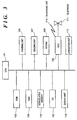
- Fig. 3 is a block diagram showing the electrical construction of the facsimile apparatus in Fig. 1.
- numeral 101 denotes a CPU comprising a microprocessor or the like; 102, a ROM for storing control programs and processing programs executed by the CPU 101; 103, a RAM used as a storage area for storing image data for facsimile transmission/reception or read image data for copying processing and as a work area for the CPU 101 to execute the control programs and the processing programs; 104, a non-volatile memory comprising of a DRAM or an SRAM having a backup power source, or an EEPROM, for storing information even not supplied with power from the power unit 30.
- Numeral 105 denotes a character generator (CG) which generates character patterns in accordance with character codes, represented based on a code system such as JIS codes or ASCII codes; 106, the printing unit having the construction as described in Fig. 1; 107, the reading unit having the construction as described in Fig. 1; 108, a MODEM; 109, a network control unit (NCU); 110, a telephone line; 111, a telephone; 112, an operation unit having a part of the operation panel 28 of the operation circuit board 27, as described in Fig. 1; and 113, a display unit having an LCD, LEDs and the like, with a part of the operation panel 28 of the operation circuit board 27, as described in Fig. 1.
- CG character generator
- the CPU 101 controls the ROM 102, the RAM 103, the non-volatile memory 104, the CG 105, the printing unit 106, the reading unit 107, the MODEM 108, the NCU 109, the operation unit 112, and the display unit 113.
- the RAM 103 is used for storing binary image data read by the reading unit 107 or binary image data to be printed by the printing unit 106. Also, the RAM 103 is used for storing encoded image data to be modulated by the MODEM 108 and outputted onto the telephone line 110 via the NCU 109, and encoded image data obtained from demodulating, via the NCU 109 and the MODEM 108, an analog image signal received via the telephone line 110.
- the non-volatile memory 104 is used for storing data to be held regardless of presence/absence of power supply (e.g., abbreviated telephone numbers).
- the CG 105 generates character pattern data corresponding to input codes in accordance with necessity, under the control of the CPU 101.
- the electric circuit of the printing unit 106 comprising a DMA controller, the ink-jet printhead, a CMOS logic IC and the like, reads the image data stored in the RAM 103, and print-outputs the data.
- the electric circuit of the reading unit 107 comprising a DMA controller, an image processing IC, an image sensor, a CMOS logic IC and the like, binarizes the image data read from the image sensor 22 and sequentially outputs the binary data to the RAM 103, under the control of the CPU 101.
- the status of an original which is set with respect to the reading unit 107 can be detected by an original detection unit (not shown) using a photosensor provided on an original convey path.
- the MODEM 108 comprising a G3/G2 MODEM, a clock generator connected to the MODEM and the like, modulates encoded transmission data stored in the RAM 103 and outputs the data onto the telephone line 110 via the NCU 109, otherwise, inputs, via the NCU 109, an analog image signal received via the telephone line 110, demodulates the input signal to obtain encoded received data, and stores the data into the RAM 103, under the control of the CPU 101.
- the NCU 109 switches the connection of the telephone line 110 to the MODEM 108 or to the telephone 111, under the control of the CPU 101.
- the NCU 109 has a detection circuit for detecting a calling signal (CI). When the calling signal is detected, the NCU 109 sends an incoming-call signal to the CPU 101.
- CI calling signal
- the telephone 111 is integrated with the facsimile apparatus main body, comprising a handset, a speech network, a dialer, ten-keys, single-touch keys and the like.
- the operation unit 112 comprises a start key to start image transmission/reception, a resolution selection key to switch resolution of the facsimile image upon transmission/reception to fine mode, standard mode and the like, a mode selection key to designate operation mode upon automatic reception and the like, ten-keys and single-touch keys for dialing, and the like.
- the display unit 113 comprises an LCD module including a seven-segmented LCD for time display, an iconic LCD for displaying icons representing various modes, a matrix LCD for displaying 5 ⁇ 7 dots (one character) ⁇ one line, LEDs, and the like.
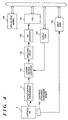
- Fig. 4 is a block diagram showing the electrical construction of the residual-ink detection unit.
- numeral 151 denotes a current/voltage converter for converting current into a voltage corresponding to the intensity of the output current from the photosensor 11; 152, a smoothing circuit which eliminates noise caused by the movement of the ink cartridge 9, and minimizes variation in output voltage due to ripples of the ink surface also caused by the movement of the ink cartridge 9; 153, an A/D converter; 154, an output port for supplying a switching signal (described later) to the current/voltage converter 151 in accordance with a control signal from the CPU 101; 155, an input port to input outputs from various sensors and output the signals to the CPU 101; and 156, a cartridge attachment/detachment sensor for detecting whether the ink cartridge 9 is attached to the carriage 10 or not.
- the current/voltage converter 151 can vary the ratio of current/voltage conversion by the switching signal from an external device (CPU 101), and the output from the A/D converter 153 is inputted into the CPU 101.
- Fig. 5 is a block diagram showing the detailed construction of the current/voltage converter 151.
- the output from the photosensor 11 is at a low level, consequently, a low-level signal is inputted into the A/D converter 153.
- the output from the photosensor 11 is at a high level, consequently, a high-level signal is inputted into the A/D converter 153.
- a switch 157 is opened/closed (ON/OFF) in accordance with an ON/OFF signal from the output port 154.
- numeral 158 denotes a capacitor for smoothing.
- the capacitor 158 functions to smooth the signal with the above resistance element.
- the mechanically driven unit When print operation is required for copying an original or printing a received facsimile image signal, the mechanically driven unit (not shown) rotates to drive the print-sheet separation roller 5 in the clockwise direction. At the same time, the operation of a cam as a part of the mechanically driven unit releases downward depressing of the intermediate board 3. The intermediate board 3, then pressed by the spring 4, pivots to bring the top of the plural print sheets on the ASF chassis 2 into contact with the print-sheet separation roller 5. Further, as the print-sheet separation roller 5 rotates, only the top print sheet is conveyed in a left-downward direction, to a contact point between the print-sheet convey roller 7 and the print-sheet convey rod 8. In the meantime, print-sheet detection sensor (not shown) detects a top-end position of the print sheet, then a print-sheet convey amount is calculated based on this detection result.
- the print sheet, held between the print-sheet convey roller 7 and the print-sheet convey rod 8, is further conveyed in the leftward direction.
- the rotation speed of the print-sheet separation roller 5 is a little faster than that of the print-sheet convey roller 7, the friction force between the print sheet and the print-sheet separation roller 5 does not become load against the convey force of the print-sheet convey roller 7.
- the print sheet is conveyed, it is also held between the print-sheet discharge roller 15 and the print-sheet discharge rod 16.
- the print-sheet convey speed of this pair of rollers is faster than that of the print-sheet convey roller 7, but the convey force of the pair of rollers is far less than that of the print-sheet convey roller 7. Therefore, the print-sheet convey amount is determined by the print-sheet convey roller 7, and the print sheet is lightly tensed.
- the print-sheet separation roller 5 rotates one cycle and the roller position sensor 6 detects the home position of the print-sheet separation roller 5, the print-sheet separation roller 5 stops. Immediately before this operation, the intermediate board 3 is again pressed downward by the cam (not shown) as in the stand-by status. Thereafter, the rotations of the print-sheet convey roller 7 and the print-sheet discharge roller 14 are reversed, then the print sheet is conveyed in the reversed direction, in accordance with the print-sheet convey amount evaluated from the point where the top end of the print sheet has been detected by the print-sheet detection sensor, thus positioning of the print sheet is made such that the top end of the print sheet comes to the print position of the printhead.
- printing is performed by scanning the carriage 10 in the main-scanning direction while selectively discharging ink from the nozzles in accordance with image data.
- the print-sheet convey roller 7 and the print-sheet discharge roller 15 are rotated in the counterclockwise direction (regular rotation), to convey the print sheet by a predetermined amount (the print width of the printhead) in the leftward direction while the carriage 10 moves backward.
- printing is performed again by scanning the carriage 10 in the main-scanning direction (forward scanning) while selectively discharging the ink from the nozzles. This operation is repeated to form a print image over the print sheet.
- the print-sheet detection sensor detects the rear end of the print sheet, print operation for one print sheet is finished.
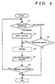
- step S1 whether or not the ink remains is examined by using the result of detection by the residual-ink detection unit. If it is determined that the ink remains, the processing proceeds to step S2, while if it is determined that the ink is exhausted, the processing proceeds to step S6. Note that the residual-ink detection will be described in detail later.
- a count value (CNT) of an ink-discharge amount counter (hereinafter simply referred to as "counter”) set in the non-volatile memory 104 is reset.
- This counter is used for counting the ink-discharge amount in print operation after it is determined that the ink is exhausted. when ink remains, this counter is not used, then the count value is reset.
- printing here this means printing for the print width of the printhead, performed by one scanning of the printhead in the main-scanning direction) on a print sheet is performed.
- step S4 the counter evaluates the ink-discharge amount by examining the number of pixels for actual ink discharge for one print operation (hereinafter referred to as "number of print dots").
- step S5 whether or not the series of print operation has been completed is examined. If it is determined that the print operation has been completed, the processing ends, while if it is determined that the print operation is continued, the processing returns to step S1 to repeat the above operation.
- the ink-discharge amount i.e., the count value of the counter (CNT) is compared with a predetermined threshold value (n). If CNT ⁇ n holds, the processing proceeds to step S3, while if CNT ⁇ n holds, the processing ends.
- the residual-ink detection unit directly detects a residual-ink amount of the liquid ink, even though it is determined, due to the structure of the ink cartridge as shown in Fig. 2, that the ink is exhausted, printing is still possible because there is a small amount of ink reservoir and in the sponge 92. Accordingly, to obtain the available amount of ink for further printing, it is necessary to perform print control such that printing can be made after it is determined that the ink is exhausted (hereinafter referred to as "further-discharging control"). This control is particularly indispensable to an apparatus using a disposable type ink cartridge as the present embodiment.
- the predetermined threshold value (n) is determined by evaluating a residual-ink amount when the residual-ink detection unit detects that the ink is exhausted. Further, this value allows printing in any case, in consideration of difference in residual-ink detection precision, variation of ink-discharge amount due to temperature change of environment where the apparatus is installed, variation of ink-discharge amount due to difference in product quality of each printhead, change of ink-discharge amount depending on a print pattern or a print history.
- the printing unit 106 has function of idle-discharge of ink for maintaining discharging performance or function of suction (suction recovery) of ink from discharge orifices (nozzles) by a pump, it may be arranged such that the discharged ink amount or sucked ink amount is evaluated and the evaluation result is fed-back to the determination of the predetermined threshold value (n).
- processing to stop printing will be briefly described. Normally, upon determination on stoppage of printing, it is considered that printing has not been completed on the current print sheet, then data reception is switched to alternative processing to store the received data (e.g., in facsimile image signal receiving) into a memory from the head line or head scan of the corresponding page, so that printing can be restored. Especially, since the receiving side does not have an original in facsimile image reception, it is necessary to handle received data to be printed at any time.
- the printing stoppage processing is immediately performed, however, print control may be performed such that the printing on the current page is continued on any condition, and at a point of completion of the printing of the page, the process ends.
- a user when printing accompanying copying operation is performed, a user is near the apparatus and can take appropriate actions.
- it may be arranged such that only a warning message is displayed on the display unit 113 to notify the user of the shortage of ink, then the printing is continued by the end of the current print sheet, and handling thereafter is left to the user.
- the present apparatus is capable of two print operations, facsimile reception and copying, and when such print operation occurs is not known in advance. Therefore, considering that facsimile reception operation may occur at any time, the detection of residual-ink amount, the evaluation of ink-discharge amount, the comparison of the ink-discharge amount with the predetermined threshold value are always necessary. It is preferable that as soon as it is determined that the ink-discharge amount exceeds the predetermined amount, a warning is given to the user.
- residual-ink detection is performed by using the reflection board 93 provided in the ink cartridge 9 and the photosensor 11. That is, the photosensor 11 emits light, the reflection board 93 reflects the light, then the reflected light is received by the photosensor 11, and the residual-ink amount is determined by the intensity of the reflection light received by the photosensor 11.
- the photosensor 11 and the reflection board 93 are both provided along the moving direction (main-scanning direction) of the carriage 10, and the photoreceptor surface of the photosensor and the reflection surface of the reflection board 93 are vertical to the main-scanning direction.
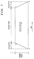
- Fig. 7 is a line graph showing the change of moving speed of the carriage. Especially, Fig. 7 shows a case where the carriage 10 scans forward (this direction is referred to as "regular direction"). As shown in Fig. 7, the carriage 10 mounting the ink cartridge 9 moves at speed that changes as points A ⁇ B ⁇ C ⁇ D.
- the A ⁇ B portion represents acceleration; where the carriage 10 at its home position starts to move, then accelerates its moving speed, to a predetermined speed (X) as a constant speed (this is referred to as "ramp up”).
- the B ⁇ C portion represents constant speed (X) at which the carriage 10 moves while performing printing at the constant speed (X).
- the C ⁇ D portion represents deceleration where the carriage 10 mounting the printhead gradually stops with decelerating its moving speed from the constant speed (X) at a predetermined negative acceleration (this is referred to as "ramp down").
- acceleration acts on the ink cartridge 9. That is, in the acceleration portion A ⁇ B of the regular direction movement (forward scanning) and in the deceleration of the reversed direction movement (backward scanning), the ink surface in the ink cartridge 9 is as shown in Fig. 8. On the other hand, in the deceleration portion C ⁇ D of the regular direction movement (forward scanning) and in the acceleration of the reversed direction movement (backward scanning), the ink surface in the ink cartridge 9 is as shown in Fig. 9. Note that when the carriage 10 is moving at a constant speed or stands still, no acceleration acts on the ink cartridge 9, therefore, the ink surface of the ink cartridge 9 at this time is as shown in Fig. 2.
- the ink surface in the ink cartridge 9 (exactly, the interval between the side wall of the ink cartridge 9 on which the photosensor 11 is provided outside and the reflection board 93) changes in correspondence with the movement of the carriage 10.
- the same residual-ink amount is determined as "the ink is exhausted” at one timing or "the ink remains” at another timing, depending upon the change of the ink surface. In other words, it is determined that the ink is seemingly exhausted, otherwise it is determined that the ink remains though the ink is actually exhausted, due to the change of the ink surface.
- residual-ink detection is performed when the status of the ink surface is as shown in Fig. 8. In this detection, even when the residual-ink amount is very small, it can be detected that the ink remains, in addition, the residual-ink can be more accurately detected.
- the above three statuses as residual-ink amount detection timings respectively correspond to accelerated motion (A ⁇ B), uniform motion (B ⁇ C) and decelerated motion (C ⁇ D) of the carriage 10.
- timing of residual-ink detection can be taken in connection with the driving of a carriage motor for the carriage 10, thus attaining the residual-ink amount detection at appropriate timing.
- a pulse motor is employed as a drive power for the carriage 10
- change of the moving status such as the ramp up and ramp down of the carriage 10 can be used as reference timing for the residual-ink amount detection.
- the obtained detection result is used for determination on the amount of residual ink at step S1.
- the present embodiment performs residual-ink detection, on the same condition of the ink surface, or, in the earlier described example which does not form part of the present invention, performs residual-ink detection on plural conditions of the ink surface and synthetically evaluates the detection results. This attains more accurate residual-ink detection, and realises more precise print control based on residual-ink amount.
- the detection result may be displayed as a message on the LCD of the display unit 113, or as lighting of particular LED(s), so as to notify the user of the shortage of ink. This can provide more user-friendly apparatus.
- ink-discharging period time interval between residual-ink amount detections, the number of pages to be printed, the number of print dots and the like are counted so as to grasp the status of use of the apparatus and perform apparatus control based on the information. For example, if the ink-consuming period for each printing is stored, when it is detected that the ink is exhausted, time at which the ink is completely exhausted can be predicted based on the accumulated ink-consuming period, and display control can be performed so as to notify the user of the predicted time with a message.
- step S11 whether or not print operation is required is examined. If YES, the processing proceeds to step S12, on the other hand, if NO, proceeds to step S17.
- step S12 print operation (printing for the print width of the printhead executed by one-scanning of the printhead in the main-scanning direction) is performed on a print sheet.
- the number of ink-discharge dots (DN) necessary for the print operation is measured.
- step S13 whether or not ink remains is examined by using the result of detection by the residual-ink detection unit. If it is determined that ink remains, the processing proceeds to step S14, while if it is determined that the ink is exhausted, proceeds to step S16. Note that the residual-ink detection will be described in detail later.
- step S14 initial-setting of the counter, whose value is set in the non-volatile memory 104, is performed again.
- this counter is a decrementing counter in this embodiment, in this setting, a predetermined positive threshold value (CNT: for further-discharge amount) is set. If it is determined that the ink is exhausted, the counter is used for counting the ink-discharge amount in printing after the determination. If it is determined that the ink remains, the counter is not used.
- CNT for further-discharge amount
- step S15 the count value (CNT) is compared to "0". If CNT > 0 holds, it is determined that printing is possible, then the processing returns to step S11 to repeat the above operation. On the other hand, if CNT ⁇ 0 holds, it is determined that printing is impossible, then the processing proceeds to step S21, at which the print operation is forcibly terminated. Thereafter, the processing ends.
- step S16 the number of ink-discharge dots (DN) obtained at step S12 is subtracted from the count value (CNT) to obtain a difference as a new count value (CNT). Then the processing proceeds to step S15.
- step S17 whether or not recovery requirement has been made is examined. If YES, the processing proceeds to step S18, while if NO, returns to step S11 to repeat the above operation.
- recovery operation is performed. This is a series of operations to restore (recover) usable status by sucking the ink-discharge orifices (nozzles) clogged with dust and dried ink by using a pump.
- the recovery operation is usually realized by two methods: (1) manual recovery operation where a user checks good/poor image quality from a printed image and performs recovery by manual operation; and (2) automatic recovery operation performed at a fixed intervals (e.g., 72 hours) utilizing a timer, mainly for preventing clogging of the ink-discharge orifices with dried ink.
- the recovery operation can be performed by any method.
- the ink-discharge amount value (S) is a predetermined constant to be described later.
- the count value (CNT) is compared with the predetermined threshold value (n). If CNT > n holds, the processing returns to step S1 to repeat the above operation. On the other hand, if CNT ⁇ n holds, the processing proceeds to step S21, to forcibly terminate the print operation, then the processing ends. Note that the threshold value (n) will be described later.
- the print control processing is repeated through the route of steps S11 ⁇ S12 ⁇ S13 ⁇ S14 ⁇ S15 ⁇ S11.... performing printing.
- the predetermined threshold value (CNT) is always set as the initial value at step S14
- the count value (CNT) is maintained as a constant value.
- the print control processing advances through the route of steps S11 ⁇ S17 ⁇ S18 ⁇ S19 ⁇ S20 ⁇ S11. Even though the count value temporarily decreases, it becomes the same value through the residual-ink amount detection at step S13 and the re-setting of initial value at step S14.
- step S13 if the ink has decreased and_ it is determined at step S13 that the ink is exhausted, the processing advances through the route of steps S11 ⁇ S12 ⁇ S13 ⁇ S16 ⁇ S15 ⁇ S11....
- the number of ink-discharge dots (DN) corresponding to actual ink-discharging per one print operation, evaluated at step S12 is subtracted from the count value (CNT) at step S16, thus the count value gradually decreases. Further, printing proceeds and the count value (CNT) becomes "0" or less, CNT ⁇ 0 holds at step S15, then the printing is forcibly terminated.
- this amount is obtained by subtracting a constant (S), which is the number of ink-discharge dots converted from ink-consumption amount in one recovery operation, from the count value (CNT).
- S a constant
- CNT count value
- the converted value (S) is set in consideration of variations in nozzles which occur in manufacturing process, variation in the amount of ink sucked by the pump provided in the apparatus, variation in an ink-suck amount due to of temperature change, and the like.
- the count value may be greater than the actual residual-ink amount by an ink-consumption amount by the recovery operation.
- the apparatus in case of facsimile image reception, the apparatus must avoid normal reception operation if the ink is exhausted. In this reception, as the apparatus on the receiving side has no original, it must print all the received data on printing sheets, store the data into a memory until printing becomes possible again, or inform the transmitting side that the facsimile reception is impossible not to perform normal facsimile communication.
- step S19 the value corresponding to the amount of ink consumed in the recovery operation is subtracted from the count value regardless of existence/shortage of ink.
- step S13 if it is determined during the print operation that the ink remains, the predetermined threshold value is set again as the initial value of the counter at step S14. This cancels the difference between the previous recovery operation and the latest printing operation.
- the ink cartridge 9 has a sponge 92 to supply ink to the printhead 94 always under a constant pressure, and the ink tank containing liquid-state ink to supply the ink little by little to the sponge 92.
- the sponge 92 works as a buffering material. As residual-ink detection is performed with respect to the liquid ink in the ink tank, even if it is detected that the ink is exhausted, there is a little amount of ink in the ink tank and the sponge 92. Under this condition, printing is continued while performing further-discharge control, until the ink in the ink tank is completely exhausted, and only the ink included in the sponge 92 exists.
- the ink included in the sponge 92 is supplied through an ink-introduction pipe (not shown) in contact with the sponge 92.
- the ink included in the sponge 92 is continuously supplied by surface tension.
- the ink viscosity, the surface tension, the sponge material/density, the diameter of the ink-introduction pipe and the like are set for this purpose.
- print control determines whether or not to forcibly terminate print operation after the ink has been consumed in recovery operation during further-discharge control, and similar print control after the ink has been consumed in print operation during further-discharge control, must be separately made. Otherwise, even if the residual ink is too little to perform normal printing, further-discharge control to continue printing is performed, which is inconvenient to, especially, facsimile reception operation.
- the count value (CNT) is compared with the predetermined threshold value (n) at step S20 so that determination (whether or not forced termination of printing after recovery operation should be made) can be made independent of the determination at step S15 (whether or not forced termination of printing after print operation should be made).
- the threshold value (n) which is greater than that at step S15 ("0") is set such that normal printing can be performed even if recovery operation is performed immediately before the ink is completely exhausted. Further, this value is determined in consideration of variation in printheads which occurs in manufacturing process, variation in pump performance, various fluctuations due to temperature change and the like.
- the ink in the ink tank decreases, there may exist transient time at which the boundary between the determination that ink remains and the determination that ink is exhausted is vague. At this time, it can be determined that ink remains, but it can also be determined that ink is exhausted, from various factors such as the moving speed of the printhead, the print width, and the inclination of the apparatus. In a case where this phenomenon occurs, if it is determined that ink remains, the print control processing advances through the route of steps S11 ⁇ S12 ⁇ S13 ⁇ S14 ⁇ S15 ⁇ S11...., and the count value (CNT) is set again at step S14. Accordingly, in print operation after the final determination that ink remains is made, the count value (CNT) starts to gradually decrease.
- the print-control processing as shown in the flowchart of Fig. 10 may be arranged such that re-setting of the count value is not made based on only one determination, but is made if it is determined after a plurality of residual-ink detections that ink remains.
- the residual-ink detection at step S13 is made in a similar manner to that described in the first embodiment, and the detection result is used for determination of the residual-ink detection at step S13.
- print operation can be continued by using the actually existing residual ink under further-discharge control. Further, even recovery operation is performed and ink is abruptly discharged, printing can be controlled in consideration of the ink-discharge amount. Furthermore, even if the recovery operation is performed during the further-discharge control, printing can be controlled in consideration of the possibility of introduction of air due to the recovery operation. Thus, print control with higher precision in consideration of effective residual-ink amount can be implemented.
- the photosensor for residual-ink detection may have erroneous operation when it receives an intense unexpected incident light such as sunlight or spotlight.
- the printing unit 106 necessarily has an opening to discharge print sheet.
- the printed image might be blurred, which causes degradation of printing quality. Accordingly, it is preferable that the printed sheet is discharged immediately after printing, and the distance from the printhead to the print-sheet discharge orifice (i.e., the opening) is short.
- the residual-ink detection unit around the printhead since there is already the residual-ink detection unit around the printhead, the external light incident from the opening may easily enter the photoreceptor of the photosensor 11.
- the printing unit 106 typically performs printing by discharging ink from upper positions downward and conveying a print sheet in a horizontal direction.
- the ink cartridge 9 is at a relatively higher position to the print-sheet discharge orifice.
- the photosensor 11 is also at a relatively higher position to the print-sheet discharge orifice.
- the photosensor 11 seldom receives external light directly, but may receive reflected light from a desk on which the apparatus is placed or a discharged print sheet.
- indoor light having a weak intensity cannot be a main cause of erroneous judgment of residual-ink detection.
- light that might cause a problem is only sunlight, especially diagonally incoming sunlight with a small incident angle, i.e., sunlight that may impinge upon the apparatus for a short period (e.g., an hour) in mornings and evenings.
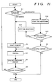
- the following processing in accordance with Fig. 11 includes print control to cope with such erroneous detection due to incident sunlight.
- step S1 if it is determined that the ink is exhausted, the processing proceeds to step S36. Note that the residual-ink detection at step S1 is the same as that described in the first embodiment.
- step S36 time evaluation as shown in the flowchart of Fig. 12 is started from the time (T0) at which the shortage of ink is determined. This processing is performed in parallel to the print control by the CPU 101 as shown in Fig. 11. Hereinafter, the time evaluation will be described with reference to Fig. 12.
- step S41 whether or not a predetermined period has elapsed from the time T0 is examined. This is made on the assumption that the impingement of sunlight must occur at particular time period in mornings and evenings and it does not occur after the predetermined period.
- step S42 to perform residual-ink detection again.
- step S43 to reset the count value (CNT), and the time evaluation is terminated.
- step S37 at which whether or not a new ink cartridge has been attached is examined, based on the result of detection by the cartridge attachment/detachment sensor 156.
- a connection point may be provided at an electrical connection point between the ink cartridge 9 and the carriage 10, in place of the cartridge attachment/detachment sensor 156. If it is determined that a new ink cartridge has been attached, the processing proceeds to step S38 to terminate the current time evaluation, since it is expected that the new ink cartridge is filled up with ink and residual-ink detection is unnecessary. Thereafter, the processing returns to step S2. On the other hand, if it is determined that the ink cartridge has not been changed, the processing proceeds to step S6.
- the print operation is forcibly terminated.
- the ink-discharge amount i.e., the count value (CNT) is compared with the predetermined threshold value (n). If CNT ⁇ n holds, the processing proceeds to step S3, while if CNT ⁇ n holds, the processing ends.
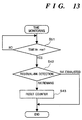
- time monitoring is performed for a predetermined period from the time of determination, and the residual-ink detection is performed again after the predetermined period. This prevents erroneous determination of residual-ink detection due to incident light such as sunlight, which might occur in a particular period in mornings and evenings, and attains more precise residual-ink detection.
- step S36 and related steps S37 and S38 may be omitted. Even if it is erroneously determined due to incident light that ink is exhausted but the ink actually remains, as the incident light disappears with passage of time or in the progress of printing, it is determined in the next residual-ink detection that the ink remains, and print operation can be normally restored, without the processings at steps S36 to S38.
- the embodiment described above has exemplified a printer, which comprises means (e.g., an electrothermal transducer, laser beam generator, and the like) for generating heat energy as energy utilized upon execution of ink discharge, and causes a change in state of an ink by the heat energy, among the ink-jet printers.
- means e.g., an electrothermal transducer, laser beam generator, and the like
- heat energy as energy utilized upon execution of ink discharge
- causes a change in state of an ink by the heat energy among the ink-jet printers.
- the system is effective because, by applying at least one driving signal, which corresponds to printing information and gives a rapid temperature rise exceeding film boiling, to each of electrothermal transducers arranged in correspondence with a sheet or liquid channels holding a liquid (ink), heat energy is generated by the electrothermal transducer to effect film boiling on the heat acting surface of the printhead, and consequently, a bubble can be formed in the liquid (ink) in one-to-one correspondence with the driving signal.
- the driving signal is applied as a pulse signal, the growth and shrinkage of the bubble can be attained instantly and adequately to achieve discharge of the liquid (ink) with the particularly high response characteristics.
- signals disclosed in U.S. Patent Nos. 4,463,359 and 4,345,262 are suitable. Note that further excellent printing can be performed by using the conditions described in U.S. Patent No. 4,313,124 of the invention which relates to the temperature rise rate of the heat acting surface.
- the arrangement using U.S. Patent Nos. 4,558,333 and 4,459,600 which disclose the arrangement having a heat acting portion arranged in a flexed region is also included in the present invention.
- the present invention can be effectively applied to an arrangement based on Japanese Patent Laid-Open No. 59-123670 which discloses the arrangement using a slot common to a plurality of electrothermal transducers as a discharge portion of the electrothermal transducers, or Japanese Patent Laid-Open No. 59-138461 which discloses the arrangement having an opening for absorbing a pressure wave of heat energy in correspondence with a discharge portion.
- an exchangeable chip type printhead which can be electrically connected to the apparatus main unit and can receive an ink from the apparatus main unit upon being mounted on the apparatus main unit or a cartridge type printhead in which an ink tank is integrally arranged on the printhead itself can be applicable to the present invention.
- recovery means for the printhead, preliminary auxiliary means, and the like provided as an arrangement of the printer of the present invention since the print operation can be further stabilized.
- examples of such means include, for the printhead, capping means, cleaning means, pressurization or suction means, and preliminary heating means using electrothermal transducers, another heating element, or a combination thereof. It is also effective for stable printing to provide a preliminary discharge mode which performs discharge independently of printing.
- a printing mode of the printer not only a printing mode using only a primary color such as black or the like, but also at least one of a multi-color mode using a plurality of different colors or a full-color mode achieved by color mixing can be implemented in the printer either by using an integrated printhead or by combining a plurality of printheads.
- the ink is a liquid.
- the present invention may employ an ink which is solid at room temperature or less and softens or liquefies at room temperature, or an ink which liquefies upon application of a use printing signal, since it is a general practice to perform temperature control of the ink itself within a range from 30°C to 70°C in the ink-jet system, so that the ink viscosity can fall within a stable discharge range.
- an ink which is solid in a non-use state and liquefies upon heating may be used.
- an ink which liquefies upon application of heat energy according to a printing signal and is discharged in a liquid state, an ink which begins to solidify when it reaches a printing medium, or the like, is applicable to the present invention.
- an ink may be situated opposite electrothermal transducers while being held in a liquid or solid state in recess portions of a porous sheet or through holes, as described in Japanese Patent Laid-Open No. 54-56847 or 60-71260.
- the above-mentioned film boiling system is most effective for the above-mentioned inks.
- the ink-jet printer of the present invention may be used in the form of a copying machine combined with a reader, and the like, or a facsimile apparatus having a transmission/reception function in addition to an image output terminal of an information processing equipment such as a computer.
- the present invention can be applied to a system constituted by a plurality of devices, or to an apparatus comprising a single device. Furthermore, it goes without saying that the invention is applicable also to a case where the object of the invention is attained by supplying a program to a system or apparatus.
Description
- This invention relates to a printing apparatus and facsimile apparatus using the printing apparatus and, more particularly to a printing apparatus that performs printing in accordance with an ink-jet printing method and facsimile apparatus using the printing apparatus.
- Conventionally, printers that perform printing in accordance with an ink-jet printing method employ various techniques as described below to detect the amount of residual ink in their ink tank.
- Japanese Patent Application Laid-Open No. 2-102061 discloses a reflective type photosensor, with a reflection board provided in an ink tank, to detect shortage of ink. In Japanese Patent Application Laid-Open No. 56-144184, to avoid degradation of detection precision due to ripples of the ink surface, ink shortage status is notified after a predetermined period from detection of the status.
- Further, a control method utilizing a photo-interruptive type sensor with an electrode provided in an ink tank is known. An electric signal which varies in accordance with change of residual-ink amount is obtained from the sensor, and if it is determined in accordance with the detected signal that the ink is exhausted, immediately print operation is stopped.
- However, in the above conventional art, since a photosensor is used for the residual-ink detection, temporary impingement of external light such as sunlight or intense spot light on a photoreceptor of an residual-ink detection sensor causes erroneous determination of ink shortage.
- Further, for the residual ink detection, to detect a photosensor output, the above prior art uses a circuit which requires adjustment due to fluctuation of the sensor output, the secular change of sensor characteristic, and variation in sensing mechanism, which exceed allowable values. Further, as the ink cartridge itself trembles due to vibration of the apparatus or the like, noise may be mixed in the residual-ink detection, otherwise, the sensor output varies due to ripples of the ink surface, thus degrading the precision of residual-ink detection.
- Further, the conventional residual-ink detecting technique has a drawback that it cannot detect status where the ink is completely exhausted. For example, as a typical conventional art, in an ink tank containing a sponge at an internal portion for preventing ink leakage, ink is first supplied to the sponge from an ink reservoir portion, and the ink is supplied to a printhead from the sponge fully containing the ink. In this ink tank, the amount of ink contained in the sponge cannot be detected by the aforementioned techniques.
- Accordingly, in the above control method, since the print operation is stopped even when ink remains in the sponge, the residual ink in the sponge cannot be used for printing.
- To solve this problem, an apparatus which performs print control so as to perform ink discharge while counting the number of dots after it is determined that ink is exhausted, and continue printing until the counted number of dots becomes a predetermined value (this is referred to as "further-discharging control"), has been proposed.
- However, this construction cannot be applied to an apparatus having a suction-recovery mechanism that performs periodical or intermittent sucking on nozzles by a pump or the like to prevent ink clogging, unless the amount of ink consumed by this suction recovery is considered.
- EP-A-0573274 discloses a printing apparatus in which a detecting circuit for detecting an amount of ink in an ink tank is actuated when a carriage of the printing apparatus arrives at a detecting position.
- In a first aspect the present invention provides a printing apparatus for printing on a printing medium by discharging ink from a printhead, as claimed in
claim 1. - In a second aspect the present invention provides a residual-ink detection method, as claimed in
claim 24. - Further aspects of the present invention are as claimed in the dependent claims.
- Other features and advantages of the present invention will be apparent from the following description taken in conjunction with the accompanying drawings, in which like reference characters designate the same name or similar parts throughout the figures thereof.
- The accompanying drawings, which are incorporated in and constitute a part of the specification, illustrate embodiments of the invention and, together with the description, serve to explain the principles of the invention.
- Fig. 1 is a cross-sectional view showing the mechanical structure of a facsimile apparatus having a printing unit in accordance with an ink-jet printing method, as a typical embodiment of the present invention;
- Fig. 2 is a partial-cutaway view showing the
detailed construction of an
ink cartridge 9; - Fig. 3 is a block diagram showing the electrical construction of the facsimile apparatus in Fig. 1;
- Fig. 4 is a block diagram showing the electrical construction of a residual-ink detection unit;
- Fig. 5 is a block diagram showing the detailed
construction of a current/
voltage converter 151; - Fig. 6 is a flowchart showing the outline of print control processing based on a residual-ink amount, according to a first embodiment;
- Fig. 7 is a line graph showing the change of moving speed of a carriage;
- Figs. 8 and 9 are cross-sectional views
respectively showing the surface of the ink in the
ink cartridge 9 at accelerated/decelerated motion of the carriage; - Fig. 10 is a flowchart showing the outline of print control processing based on a residual-ink amount, according to a second embodiment;
- Fig. 11 is a flowchart showing the outline of print control processing based on a residual-ink amount, according to a third embodiment;
- Fig. 12 is a flowchart showing the residual-ink detection control with time monitoring; and
- Fig. 13 is a flowchart showing another example of the residual-ink detection control with time monitoring.
-
- Preferred embodiments of the present invention will now be described in detail in accordance with the accompanying drawings.
- Fig. 1 is a cross-sectional view showing the mechanical structure of a facsimile apparatus having a printing unit in accordance with an ink-jet printing method, as a typical embodiment of the present invention.
- First, the construction of the printing unit of the facsimile apparatus will be described.
- In Fig. 1,
reference numeral 1 denotes a frame (main frame) as a main constituent of the overall apparatus; 2, an ASF (Auto Sheet Feeder) chassis attached to theframe 1, as a cassette of the ASF for holding plural print sheets and feeding the sheets into the printing unit one by one; 3, an intermediate board rotatably attached to theASF chassis 2; and 4, a spring for biasing the intermediate board 3 upward in a clockwise direction; 5, a print-sheet separation roller which rotates in the clockwise direction by a mechanically driven unit (not shown); and 6, a photo-interruptive type sensor (hereinafter referred to as "roller-position sensor") for detecting a home position of the print-sheet separation roller 5. - It should be noted that the position of the intermediate board 3 in Fig. 1 corresponds to a stand-by status where it is pivoted in a counterclockwise direction and stopped by a cam (not shown) provided in the mechanically driven unit (not shown), controlling the movement of the intermediate board 3. When the cam is disengaged, the intermediate board 3 rotates in the clockwise direction, and the intermediate board 3 or the print sheet comes into contact with the outer circumferential portion of the print-
sheet separation roller 5. Further, the movement of the intermediate board 3 and the position of an aspherical portion of the print-sheet separation roller 5 are in synchronization with each other. - Numeral 7 denotes a print-sheet convey roller which rotates in the counterclockwise direction by the mechanically driven unit (not shown); and 8, a print-sheet convey rod, provided around the print-
sheet convey roller 7, in contact with the print-sheet conveyroller 7 by a spring (not shown). The print-sheet conveyroller 7 and the print-sheet conveyrod 8 clamp the print sheet at a position where they are in contact with each other, and convey the print sheet in the leftward direction in Fig. 1 (hereinafter referred to as "subscanning direction"). Numeral 9 denotes an exchangeable (disposable) type ink cartridge integrating a printhead in accordance with the ink-jet printing method and an ink tank as an ink reservoir; and 10, a carriage to which theink cartridge 9 is detachably attached. - The printing surface of the
ink cartridge 9 is at the bottom part of theink cartridge 9 in Fig. 1, and it has a plurality of nozzles arrayed in a transverse direction, forming the printing-surface. Upon printing, theink cartridge 9 is moved in an orthogonal direction to the nozzle arrangement direction (i.e., vertical direction with respect to the figure; hereinafter referred to as "main-scanning direction"). Printing on a printing area for print width is performed by selectively discharging ink from those nozzles. Thereafter, the print sheet is shifted by the print width in the subscanning direction. Thus printing is made on the print sheet by repeating this printing operation (This printing method is called a "multiscan method"). A residual-ink detection sensor (ink sensor), comprising a photosensor, is attached to thecarriage 10, for detecting the amount of residual ink in theink cartridge 9. The detection direction of the ink sensor is approximately the same as the main-scanning direction of theink cartridge 9. Since the ink sensor is attached to thecarriage 10, the ink sensor moves with theink cartridge 9 as thecarriage 10 moves. Note that this movement will be described in detail later. - Numerals 12 and 13 denotes guide rails for assisting the reciprocating movement of the
carriage 10 in the main-scanning direction. Thecarriage 10 is attached to theseguide rails paper discharge rod 16 is biased by a press member (not shown) against thepaper discharge roller 15. Thepaper discharge roller 15 and thepaper discharge rod 16 hold discharge the print sheet while holding the print sheet at a contact portion between them. Numeral 17 denotes a cover (print-sheet cover) which opens downward with a bottom portion of the apparatus as its pivotal axis. - Next, the construction of a reading unit of the facsimile apparatus will be described.
-
Numeral 20 denotes a reading separation roller which rotates in the counterclockwise direction by the mechanically driven unit (not shown) and conveys each of plurality of originals in the leftward direction in Fig. 1 one by one; 21, a separation piece, comprising of high-friction material such as rubber, biased by a press member (not shown) against the readingseparation roller 20, for separating the plurality of originals one by one; 22, a contact type line image sensor (hereinafter referred to as "image sensor") which reads images on the originals and converts the read image information into electric signals; 23, a CS spring; and 24, a white CS roller which rotates in the clockwise direction by the mechanically driven unit (not shown). TheCS spring 23 presses theimage sensor 22 against theCS roller 24. TheCS roller 24 brings the original into tight contact with the entire reading surface of theimage sensor 22, conveys the original in the leftward direction in Fig. 1, and functions as a background in original reading. -
Numeral 25 denotes an original guide, fixed to theframe 1 that supports (as a part of the apparatus body) the reading unit and an operation panel (described later), for guiding the back surface of the original; 26, an original guide, fixed to theoriginal guide 25, for guiding the front surface of the original; 27, an operation circuit board having operation switches; and 28, the operation panel, to which theoperation circuit board 27 is fixed. Theoperation panel 28 itself is fixed to theoriginal guide 25. -
Numeral 30 denotes a power unit comprising a power transformer, a capacitor and the like; and 31, an electric control board, attached to theframe 1, for controlling the operation of the overall apparatus. Theelectric control board 31 is connected with all wires and cables from electric devices, divided into the respective parts, components (theimage sensor 22, theoperation circuit board 27, thepower unit 30, theink cartridge 9, respective drive motors (not shown), theroller position sensor 6, and respective sensors (not shown)). Note that various sensors including a sensor for detecting presence/absence of print sheet, which are not described here, are directly integrated onto theelectric control board 31 without using wires and cables. Further, all the external interfaces (e.g., a public telephone line network interface, an auxiliary sub-telephone interface, an external sub-telephone interface, and a personal-computer interface such as a centronics interface) are connected to theelectric control board 31. - Fig. 2 is a partial-cutaway view showing the detailed construction of the
ink cartridge 9. In Fig. 2, numeral 11 denotes a reflection type photosensor (hereinafter referred to as "photosensor"); 91, ink; 92, a sponge; 93, a reflection board for reflecting light from thephotosensor 11; and 94, a printhead. Fig. 2 especially shows status where thecarriage 10 and theink cartridge 9 to be mounted on thecarriage 10 stand still. Accordingly, the surface of theink 91 is smooth without ripples. - It is apparent from Fig. 2, the
reflection board 93 is provided around the bottom of the ink cartridge, at a position near a ink-cartridge side wall, around which thephotosensor 11 for thereflection board 93 is provided. This arrangement of thereflection board 93 around thephotosensor 11 is intended to enhance the intensity of reflected light to be received by thephotosensor 11, and improve S/N ratio in residual-ink detection. The interval (detection gap) between ink-cartridge side wall on the photosensor 11 side and thereflection board 93 is set, in consideration of the ink-surface tension and the water repellent relation among the side wall, the ink, and the reflection board, so as not to gather ink between the photosensor 11 and the side wall. This interval should preferably be 2 to 4 mm for more accurate residual-ink detection. - Further, right space and left space with respect to the
reflection board 93 provided as above are not separate reservoirs but are connected. In other words, as shown in Fig. 2, the depth of thereflection board 93 does not occupy the full depth of theink cartridge 9 but occupies a part of the depth of theink cartridge 9. That is, thereflection board 93 is positioned around the central portion of the depth. This arrangement renders the same change to the ink surface between thereflection board 93 and the photosensor 11 as that to the ink surface of the ink within other parts of the ink cartridge. In addition to this arrangement, a hole may be provided around the bottom of thereflection board 93 to obtain the same level of the ink surface, on the both sides, around thereflection board 93. - When the
ink cartridge 9 is filled up with theink 91, thephotosensor 11 hardly detects light reflected from thereflection board 93 since the light is interrupted by theink 91. At this time, the output current from thephotosensor 11 is approximately zero. On the other hand, when the ink cartridge has little or noink 91, thephotosensor 11 detects the light reflected from thereflection board 93, and as a result, outputs current corresponding to the reflection light intensity. - Fig. 3 is a block diagram showing the electrical construction of the facsimile apparatus in Fig. 1. In Fig. 3, numeral 101 denotes a CPU comprising a microprocessor or the like; 102, a ROM for storing control programs and processing programs executed by the
CPU 101; 103, a RAM used as a storage area for storing image data for facsimile transmission/reception or read image data for copying processing and as a work area for theCPU 101 to execute the control programs and the processing programs; 104, a non-volatile memory comprising of a DRAM or an SRAM having a backup power source, or an EEPROM, for storing information even not supplied with power from thepower unit 30. -
Numeral 105 denotes a character generator (CG) which generates character patterns in accordance with character codes, represented based on a code system such as JIS codes or ASCII codes; 106, the printing unit having the construction as described in Fig. 1; 107, the reading unit having the construction as described in Fig. 1; 108, a MODEM; 109, a network control unit (NCU); 110, a telephone line; 111, a telephone; 112, an operation unit having a part of theoperation panel 28 of theoperation circuit board 27, as described in Fig. 1; and 113, a display unit having an LCD, LEDs and the like, with a part of theoperation panel 28 of theoperation circuit board 27, as described in Fig. 1. - The
CPU 101 controls theROM 102, theRAM 103, thenon-volatile memory 104, theCG 105, theprinting unit 106, thereading unit 107, theMODEM 108, theNCU 109, theoperation unit 112, and thedisplay unit 113. - The
RAM 103 is used for storing binary image data read by thereading unit 107 or binary image data to be printed by theprinting unit 106. Also, theRAM 103 is used for storing encoded image data to be modulated by theMODEM 108 and outputted onto thetelephone line 110 via theNCU 109, and encoded image data obtained from demodulating, via theNCU 109 and theMODEM 108, an analog image signal received via thetelephone line 110. Thenon-volatile memory 104 is used for storing data to be held regardless of presence/absence of power supply (e.g., abbreviated telephone numbers). TheCG 105 generates character pattern data corresponding to input codes in accordance with necessity, under the control of theCPU 101. - The electric circuit of the
printing unit 106, comprising a DMA controller, the ink-jet printhead, a CMOS logic IC and the like, reads the image data stored in theRAM 103, and print-outputs the data. On the other hand, the electric circuit of thereading unit 107, comprising a DMA controller, an image processing IC, an image sensor, a CMOS logic IC and the like, binarizes the image data read from theimage sensor 22 and sequentially outputs the binary data to theRAM 103, under the control of theCPU 101. Note that the status of an original which is set with respect to thereading unit 107 can be detected by an original detection unit (not shown) using a photosensor provided on an original convey path. - The
MODEM 108, comprising a G3/G2 MODEM, a clock generator connected to the MODEM and the like, modulates encoded transmission data stored in theRAM 103 and outputs the data onto thetelephone line 110 via theNCU 109, otherwise, inputs, via theNCU 109, an analog image signal received via thetelephone line 110, demodulates the input signal to obtain encoded received data, and stores the data into theRAM 103, under the control of theCPU 101. TheNCU 109 switches the connection of thetelephone line 110 to theMODEM 108 or to thetelephone 111, under the control of theCPU 101. TheNCU 109 has a detection circuit for detecting a calling signal (CI). When the calling signal is detected, theNCU 109 sends an incoming-call signal to theCPU 101. - The
telephone 111 is integrated with the facsimile apparatus main body, comprising a handset, a speech network, a dialer, ten-keys, single-touch keys and the like. Theoperation unit 112 comprises a start key to start image transmission/reception, a resolution selection key to switch resolution of the facsimile image upon transmission/reception to fine mode, standard mode and the like, a mode selection key to designate operation mode upon automatic reception and the like, ten-keys and single-touch keys for dialing, and the like. Thedisplay unit 113 comprises an LCD module including a seven-segmented LCD for time display, an iconic LCD for displaying icons representing various modes, a matrix LCD for displaying 5 × 7 dots (one character) × one line, LEDs, and the like. - Next, the electrical construction of a residual-ink detection unit provided at the
printing unit 106 will be described. - Fig. 4 is a block diagram showing the electrical construction of the residual-ink detection unit.
- In Fig. 4, numeral 151 denotes a current/voltage converter for converting current into a voltage corresponding to the intensity of the output current from the
photosensor 11; 152, a smoothing circuit which eliminates noise caused by the movement of theink cartridge 9, and minimizes variation in output voltage due to ripples of the ink surface also caused by the movement of theink cartridge 9; 153, an A/D converter; 154, an output port for supplying a switching signal (described later) to the current/voltage converter 151 in accordance with a control signal from theCPU 101; 155, an input port to input outputs from various sensors and output the signals to theCPU 101; and 156, a cartridge attachment/detachment sensor for detecting whether theink cartridge 9 is attached to thecarriage 10 or not. Note that the current/voltage converter 151 can vary the ratio of current/voltage conversion by the switching signal from an external device (CPU 101), and the output from the A/D converter 153 is inputted into theCPU 101. - Fig. 5 is a block diagram showing the detailed construction of the current/
voltage converter 151. As apparent from Fig. 5, when theink cartridge 9 has sufficient ink, the output from thephotosensor 11 is at a low level, consequently, a low-level signal is inputted into the A/D converter 153. On the other hand, when theink cartridge 9 has little or no ink, the output from thephotosensor 11 is at a high level, consequently, a high-level signal is inputted into the A/D converter 153. Further, aswitch 157 is opened/closed (ON/OFF) in accordance with an ON/OFF signal from theoutput port 154. - When the
switch 157 is closed (ON), as the resistance is connected in parallel, the input voltage to the A/D converter 153 is smaller than that when theswitch 157 is opened (OFF). - In Fig. 5, numeral 158 denotes a capacitor for smoothing. The
capacitor 158 functions to smooth the signal with the above resistance element. - When print operation is required for copying an original or printing a received facsimile image signal, the mechanically driven unit (not shown) rotates to drive the print-
sheet separation roller 5 in the clockwise direction. At the same time, the operation of a cam as a part of the mechanically driven unit releases downward depressing of the intermediate board 3. The intermediate board 3, then pressed by thespring 4, pivots to bring the top of the plural print sheets on theASF chassis 2 into contact with the print-sheet separation roller 5. Further, as the print-sheet separation roller 5 rotates, only the top print sheet is conveyed in a left-downward direction, to a contact point between the print-sheet conveyroller 7 and the print-sheet conveyrod 8. In the meantime, print-sheet detection sensor (not shown) detects a top-end position of the print sheet, then a print-sheet convey amount is calculated based on this detection result. - The print sheet, held between the print-sheet convey
roller 7 and the print-sheet conveyrod 8, is further conveyed in the leftward direction. As the rotation speed of the print-sheet separation roller 5 is a little faster than that of the print-sheet conveyroller 7, the friction force between the print sheet and the print-sheet separation roller 5 does not become load against the convey force of the print-sheet conveyroller 7. As the print sheet is conveyed, it is also held between the print-sheet discharge roller 15 and the print-sheet discharge rod 16. The print-sheet convey speed of this pair of rollers is faster than that of the print-sheet conveyroller 7, but the convey force of the pair of rollers is far less than that of the print-sheet conveyroller 7. Therefore, the print-sheet convey amount is determined by the print-sheet conveyroller 7, and the print sheet is lightly tensed. - As the print-
sheet separation roller 5 rotates one cycle and theroller position sensor 6 detects the home position of the print-sheet separation roller 5, the print-sheet separation roller 5 stops. Immediately before this operation, the intermediate board 3 is again pressed downward by the cam (not shown) as in the stand-by status. Thereafter, the rotations of the print-sheet conveyroller 7 and the print-sheet discharge roller 14 are reversed, then the print sheet is conveyed in the reversed direction, in accordance with the print-sheet convey amount evaluated from the point where the top end of the print sheet has been detected by the print-sheet detection sensor, thus positioning of the print sheet is made such that the top end of the print sheet comes to the print position of the printhead. - Then, printing is performed by scanning the
carriage 10 in the main-scanning direction while selectively discharging ink from the nozzles in accordance with image data. As one scanning in the main-scanning direction (forward scanning) of thecarriage 10 has been completed, the print-sheet conveyroller 7 and the print-sheet discharge roller 15 are rotated in the counterclockwise direction (regular rotation), to convey the print sheet by a predetermined amount (the print width of the printhead) in the leftward direction while thecarriage 10 moves backward. Thereafter, printing is performed again by scanning thecarriage 10 in the main-scanning direction (forward scanning) while selectively discharging the ink from the nozzles. This operation is repeated to form a print image over the print sheet. Finally, as the print-sheet detection sensor detects the rear end of the print sheet, print operation for one print sheet is finished. - When printing for a plurality of print sheets is performed, the above operation is repeated for the number of the print sheets.
- Next, embodiments regarding residual-ink detection and print control based on the detection result will be described below.
- The print control based on residual-ink detection, performed by the
CPU 101 in cooperation with the residual-ink detection unit will be described with reference to the flowchart of Fig. 6. In the facsimile apparatus of this embodiment, when printing is required for printing a received facsimile image signal or for copying an image original by copying instruction, the following processing is performed. - At step S1, whether or not the ink remains is examined by using the result of detection by the residual-ink detection unit. If it is determined that the ink remains, the processing proceeds to step S2, while if it is determined that the ink is exhausted, the processing proceeds to step S6. Note that the residual-ink detection will be described in detail later.
- At step S2, a count value (CNT) of an ink-discharge amount counter (hereinafter simply referred to as "counter") set in the
non-volatile memory 104 is reset. This counter is used for counting the ink-discharge amount in print operation after it is determined that the ink is exhausted. when ink remains, this counter is not used, then the count value is reset. At step S3, printing (here this means printing for the print width of the printhead, performed by one scanning of the printhead in the main-scanning direction) on a print sheet is performed. - At step S4, the counter evaluates the ink-discharge amount by examining the number of pixels for actual ink discharge for one print operation (hereinafter referred to as "number of print dots"). At step S5, whether or not the series of print operation has been completed is examined. If it is determined that the print operation has been completed, the processing ends, while if it is determined that the print operation is continued, the processing returns to step S1 to repeat the above operation.
- At step S6, the ink-discharge amount, i.e., the count value of the counter (CNT) is compared with a predetermined threshold value (n). If CNT < n holds, the processing proceeds to step S3, while if CNT ≥ n holds, the processing ends.
- As the residual-ink detection unit directly detects a residual-ink amount of the liquid ink, even though it is determined, due to the structure of the ink cartridge as shown in Fig. 2, that the ink is exhausted, printing is still possible because there is a small amount of ink reservoir and in the
sponge 92. Accordingly, to obtain the available amount of ink for further printing, it is necessary to perform print control such that printing can be made after it is determined that the ink is exhausted (hereinafter referred to as "further-discharging control"). This control is particularly indispensable to an apparatus using a disposable type ink cartridge as the present embodiment. - For this purpose, the predetermined threshold value (n) is determined by evaluating a residual-ink amount when the residual-ink detection unit detects that the ink is exhausted. Further, this value allows printing in any case, in consideration of difference in residual-ink detection precision, variation of ink-discharge amount due to temperature change of environment where the apparatus is installed, variation of ink-discharge amount due to difference in product quality of each printhead, change of ink-discharge amount depending on a print pattern or a print history. In a case where the
printing unit 106 has function of idle-discharge of ink for maintaining discharging performance or function of suction (suction recovery) of ink from discharge orifices (nozzles) by a pump, it may be arranged such that the discharged ink amount or sucked ink amount is evaluated and the evaluation result is fed-back to the determination of the predetermined threshold value (n). - Although not directly concerned with the feature of the present embodiment, processing to stop printing will be briefly described. Normally, upon determination on stoppage of printing, it is considered that printing has not been completed on the current print sheet, then data reception is switched to alternative processing to store the received data (e.g., in facsimile image signal receiving) into a memory from the head line or head scan of the corresponding page, so that printing can be restored. Especially, since the receiving side does not have an original in facsimile image reception, it is necessary to handle received data to be printed at any time.
- As indicated in the flowchart of Fig. 6, the printing stoppage processing is immediately performed, however, print control may be performed such that the printing on the current page is continued on any condition, and at a point of completion of the printing of the page, the process ends.
- On the other hand, when printing accompanying copying operation is performed, a user is near the apparatus and can take appropriate actions. In this case, different from the above facsimile image reception, it may be arranged such that only a warning message is displayed on the
display unit 113 to notify the user of the shortage of ink, then the printing is continued by the end of the current print sheet, and handling thereafter is left to the user. - However, in any case, the present apparatus is capable of two print operations, facsimile reception and copying, and when such print operation occurs is not known in advance. Therefore, considering that facsimile reception operation may occur at any time, the detection of residual-ink amount, the evaluation of ink-discharge amount, the comparison of the ink-discharge amount with the predetermined threshold value are always necessary. It is preferable that as soon as it is determined that the ink-discharge amount exceeds the predetermined amount, a warning is given to the user.
- As described above, residual-ink detection is performed by using the
reflection board 93 provided in theink cartridge 9 and thephotosensor 11. That is, thephotosensor 11 emits light, thereflection board 93 reflects the light, then the reflected light is received by thephotosensor 11, and the residual-ink amount is determined by the intensity of the reflection light received by thephotosensor 11. As shown in Fig. 2, thephotosensor 11 and thereflection board 93 are both provided along the moving direction (main-scanning direction) of thecarriage 10, and the photoreceptor surface of the photosensor and the reflection surface of thereflection board 93 are vertical to the main-scanning direction. - Fig. 7 is a line graph showing the change of moving speed of the carriage. Especially, Fig. 7 shows a case where the
carriage 10 scans forward (this direction is referred to as "regular direction"). As shown in Fig. 7, thecarriage 10 mounting theink cartridge 9 moves at speed that changes as points A → B → C → D. - That is, the A→B portion represents acceleration; where the
carriage 10 at its home position starts to move, then accelerates its moving speed, to a predetermined speed (X) as a constant speed (this is referred to as "ramp up"). The B→C portion represents constant speed (X) at which thecarriage 10 moves while performing printing at the constant speed (X). The C→D portion represents deceleration where thecarriage 10 mounting the printhead gradually stops with decelerating its moving speed from the constant speed (X) at a predetermined negative acceleration (this is referred to as "ramp down"). - As the
carriage 10 moves as above, acceleration (inertia) acts on theink cartridge 9. That is, in the acceleration portion A→B of the regular direction movement (forward scanning) and in the deceleration of the reversed direction movement (backward scanning), the ink surface in theink cartridge 9 is as shown in Fig. 8. On the other hand, in the deceleration portion C→D of the regular direction movement (forward scanning) and in the acceleration of the reversed direction movement (backward scanning), the ink surface in theink cartridge 9 is as shown in Fig. 9. Note that when thecarriage 10 is moving at a constant speed or stands still, no acceleration acts on theink cartridge 9, therefore, the ink surface of theink cartridge 9 at this time is as shown in Fig. 2. - Thus, the ink surface in the ink cartridge 9 (exactly, the interval between the side wall of the
ink cartridge 9 on which thephotosensor 11 is provided outside and the reflection board 93) changes in correspondence with the movement of thecarriage 10. - Accordingly, the same residual-ink amount is determined as "the ink is exhausted" at one timing or "the ink remains" at another timing, depending upon the change of the ink surface. In other words, it is determined that the ink is seemingly exhausted, otherwise it is determined that the ink remains though the ink is actually exhausted, due to the change of the ink surface.
- In consideration of this problem, in an example which does not form part of the present invention, the following control is performed:
- (1) to perform residual-ink detection in the above three
statuses while monitoring the movement of the carriage,
and synthetically analyze the detection results. This
enables residual-ink detection in consideration of the
change of ink surface due to the moving status of the
carriage 10. For example, the average of the detection results from the three moving statuses of the carriage is obtained, otherwise, the detection results are integrated by time for a predetermined period (for plural scannings) to be synthetically judged. In consideration of the above problem, the present embodiment performs the following control: - (2) to perform residual-ink detection always at timing corresponding to one of the three statuses of the carriage (e.g. the status as shown in Fig. 2). This enables the residual-ink detection on the same condition of the ink surface.
-
- It is preferable that residual-ink detection is performed when the status of the ink surface is as shown in Fig. 8. In this detection, even when the residual-ink amount is very small, it can be detected that the ink remains, in addition, the residual-ink can be more accurately detected.
- As shown in Fig. 7, the above three statuses as residual-ink amount detection timings respectively correspond to accelerated motion (A→B), uniform motion (B→C) and decelerated motion (C→D) of the
carriage 10. Based on these moving statuses, timing of residual-ink detection can be taken in connection with the driving of a carriage motor for thecarriage 10, thus attaining the residual-ink amount detection at appropriate timing. Especially, if a pulse motor is employed as a drive power for thecarriage 10, change of the moving status such as the ramp up and ramp down of thecarriage 10 can be used as reference timing for the residual-ink amount detection. - In any case, the obtained detection result is used for determination on the amount of residual ink at step S1.
- Accordingly, in consideration of change of ink surface in correspondence with the movement of the carriage, the present embodiment performs residual-ink detection, on the same condition of the ink surface, or, in the earlier described example which does not form part of the present invention, performs residual-ink detection on plural conditions of the ink surface and synthetically evaluates the detection results. This attains more accurate residual-ink detection, and realises more precise print control based on residual-ink amount.
- Note that the detection result may be displayed as a message on the LCD of the
display unit 113, or as lighting of particular LED(s), so as to notify the user of the shortage of ink. This can provide more user-friendly apparatus. - Further, it may be arranged such that ink-discharging period, time interval between residual-ink amount detections, the number of pages to be printed, the number of print dots and the like are counted so as to grasp the status of use of the apparatus and perform apparatus control based on the information. For example, if the ink-consuming period for each printing is stored, when it is detected that the ink is exhausted, time at which the ink is completely exhausted can be predicted based on the accumulated ink-consuming period, and display control can be performed so as to notify the user of the predicted time with a message.
- Next, the print control based on a residual-ink amount according to a second embodiment will be described with reference to the flowchart of Fig. 10. This control is performed by the
CPU 101 in cooperation with the residual-ink detection unit. In the facsimile apparatus of this embodiment, when printing is required for receiving a facsimile image signal or for copying an original by a copying instruction, the following processing is executed. It is assumed that the power of the apparatus has been turned on, various initial settings or initialization processing, necessary for print operation, have already been performed on the counter used for evaluating the ink-discharge amount (subtraction counter; hereinafter simply referred to "counter"), whose count value is set in thenon-volatile memory 104, and the like. - At step S11, whether or not print operation is required is examined. If YES, the processing proceeds to step S12, on the other hand, if NO, proceeds to step S17.
- Next, at step S12, print operation (printing for the print width of the printhead executed by one-scanning of the printhead in the main-scanning direction) is performed on a print sheet. At this time, the number of ink-discharge dots (DN) necessary for the print operation is measured.
- At step S13, whether or not ink remains is examined by using the result of detection by the residual-ink detection unit. If it is determined that ink remains, the processing proceeds to step S14, while if it is determined that the ink is exhausted, proceeds to step S16. Note that the residual-ink detection will be described in detail later.
- At step S14, initial-setting of the counter, whose value is set in the
non-volatile memory 104, is performed again. As this counter is a decrementing counter in this embodiment, in this setting, a predetermined positive threshold value (CNT: for further-discharge amount) is set. If it is determined that the ink is exhausted, the counter is used for counting the ink-discharge amount in printing after the determination. If it is determined that the ink remains, the counter is not used. - At step S15, the count value (CNT) is compared to "0". If CNT > 0 holds, it is determined that printing is possible, then the processing returns to step S11 to repeat the above operation. On the other hand, if CNT ≤ 0 holds, it is determined that printing is impossible, then the processing proceeds to step S21, at which the print operation is forcibly terminated. Thereafter, the processing ends.
- At step S16, the number of ink-discharge dots (DN) obtained at step S12 is subtracted from the count value (CNT) to obtain a difference as a new count value (CNT). Then the processing proceeds to step S15.
- On the other hand, at step S17, whether or not recovery requirement has been made is examined. If YES, the processing proceeds to step S18, while if NO, returns to step S11 to repeat the above operation.
- At step S18, recovery operation is performed. This is a series of operations to restore (recover) usable status by sucking the ink-discharge orifices (nozzles) clogged with dust and dried ink by using a pump. The recovery operation is usually realized by two methods: (1) manual recovery operation where a user checks good/poor image quality from a printed image and performs recovery by manual operation; and (2) automatic recovery operation performed at a fixed intervals (e.g., 72 hours) utilizing a timer, mainly for preventing clogging of the ink-discharge orifices with dried ink. In this embodiment, the recovery operation can be performed by any method.
- Next, at step S19, an ink-discharge amount value (S), converted from the amount sucked by the pump, is subtracted from the count value (CNT) to obtain a difference as a new count value (CNT). The ink-discharge amount value (S) is a predetermined constant to be described later. At step S20, the count value (CNT) is compared with the predetermined threshold value (n). If CNT > n holds, the processing returns to step S1 to repeat the above operation. On the other hand, if CNT ≤ n holds, the processing proceeds to step S21, to forcibly terminate the print operation, then the processing ends. Note that the threshold value (n) will be described later.
- The above processing can be briefly outlined from the point of ink amount as follows.
- When the
ink cartridge 9 is first attached, as the ink tank contains sufficient ink, the print control processing is repeated through the route of steps S11 → S12 → S13 → S14 → S15 → S11.... performing printing. In this case, as the predetermined threshold value (CNT) is always set as the initial value at step S14, the count value (CNT) is maintained as a constant value. In the middle of the printing, recovery operation is performed, then the print control processing advances through the route of steps S11 → S17 → S18 → S19 → S20 → S11. Even though the count value temporarily decreases, it becomes the same value through the residual-ink amount detection at step S13 and the re-setting of initial value at step S14. - On the other hand, if the ink has decreased and_ it is determined at step S13 that the ink is exhausted, the processing advances through the route of steps S11 → S12 → S13 → S16 → S15 → S11.... In this case, the number of ink-discharge dots (DN) corresponding to actual ink-discharging per one print operation, evaluated at step S12, is subtracted from the count value (CNT) at step S16, thus the count value gradually decreases. Further, printing proceeds and the count value (CNT) becomes "0" or less, CNT ≤ 0 holds at step S15, then the printing is forcibly terminated.
- Accordingly, even if it is determined that the ink is exhausted, printing can be performed by using the actually existing residual ink until CNT ≤ 0 holds. The further-discharge control according to the present embodiment is performed in this manner.
- During this further-discharge control, if recovery requirement is made, the processing advances through the route of steps S11 → S17 → S18 → S19 → S20 → S11.... performing recovery operation. Thereafter, the processing advances through the route of steps S11 → S17 → S11.... into waiting status for print requirement or recovery requirement. Since the recovery operation is sucking ink by a pump as described above, the ink decreases similar to ink-discharging. However, the amount of sucked ink is evaluated independently of the evaluation of the ink-consumption amount in printing. Specifically, at step S20, this amount is obtained by subtracting a constant (S), which is the number of ink-discharge dots converted from ink-consumption amount in one recovery operation, from the count value (CNT). The converted value (S) is set in consideration of variations in nozzles which occur in manufacturing process, variation in the amount of ink sucked by the pump provided in the apparatus, variation in an ink-suck amount due to of temperature change, and the like.
- Further, there is a case that it is determined that the ink remains, but it is determined in the following recovery operation that the ink is exhausted. In such case, if counting operation for further-discharge control is performed from the point of the completion of the recovery operation, the count value may be greater than the actual residual-ink amount by an ink-consumption amount by the recovery operation.
- For example, in case of facsimile image reception, the apparatus must avoid normal reception operation if the ink is exhausted. In this reception, as the apparatus on the receiving side has no original, it must print all the received data on printing sheets, store the data into a memory until printing becomes possible again, or inform the transmitting side that the facsimile reception is impossible not to perform normal facsimile communication.
- For the above reason, as it might be determined immediately after recovery operation that the ink is exhausted, it is necessary to take the ink-consumption amount by the previous recovery operation into consideration for the further-discharge control. Accordingly, at step S19, the value corresponding to the amount of ink consumed in the recovery operation is subtracted from the count value regardless of existence/shortage of ink. On the other hand, at step S13, if it is determined during the print operation that the ink remains, the predetermined threshold value is set again as the initial value of the counter at step S14. This cancels the difference between the previous recovery operation and the latest printing operation.
- Next, recovery operation in a case where ink is exhausted from an ink cartridge as printing operation goes on will be described.
- As described above, the
ink cartridge 9 has asponge 92 to supply ink to theprinthead 94 always under a constant pressure, and the ink tank containing liquid-state ink to supply the ink little by little to thesponge 92. In other words, thesponge 92 works as a buffering material. As residual-ink detection is performed with respect to the liquid ink in the ink tank, even if it is detected that the ink is exhausted, there is a little amount of ink in the ink tank and thesponge 92. Under this condition, printing is continued while performing further-discharge control, until the ink in the ink tank is completely exhausted, and only the ink included in thesponge 92 exists. - At this time, in case of consuming ink in normal print operation, as the ink is discharged from the ink-discharge orifices of the
printhead 94, the air pressure within the nozzles is lowered, corresponding to the discharged ink amount, the ink included in thesponge 92 is supplied through an ink-introduction pipe (not shown) in contact with thesponge 92. As this ink supply is made slowly, the ink included in thesponge 92 is continuously supplied by surface tension. In practice, the ink viscosity, the surface tension, the sponge material/density, the diameter of the ink-introduction pipe and the like are set for this purpose. - However, in a case where the ink is abruptly suck-discharged as in recovery operation, ink supply to the
printhead 94 cannot be made in the above manner, and air included in or around thesponge 92 is sucked. As a result, printing cannot be normally performed. Accordingly, it is apparent that if recovery operation is performed during further-discharge control, it is not always possible to perform printing by using the actually existing residual ink until the ink is completely exhausted. In other words, the effective ink amount (the amount of ink which can be actually used for printing) is smaller than the residual-ink amount. - In this embodiment, as residual-ink detection is performed with respect to the liquid ink in the ink tank, for the purpose of continuing print operation, using the residual ink within a range to allow continuous ink supply, print control appropriate to this purpose is desired. For this purpose, print control determines whether or not to forcibly terminate print operation after the ink has been consumed in recovery operation during further-discharge control, and similar print control after the ink has been consumed in print operation during further-discharge control, must be separately made. Otherwise, even if the residual ink is too little to perform normal printing, further-discharge control to continue printing is performed, which is inconvenient to, especially, facsimile reception operation.
- In consideration of the above problems, the count value (CNT) is compared with the predetermined threshold value (n) at step S20 so that determination (whether or not forced termination of printing after recovery operation should be made) can be made independent of the determination at step S15 (whether or not forced termination of printing after print operation should be made). The threshold value (n) which is greater than that at step S15 ("0") is set such that normal printing can be performed even if recovery operation is performed immediately before the ink is completely exhausted. Further, this value is determined in consideration of variation in printheads which occurs in manufacturing process, variation in pump performance, various fluctuations due to temperature change and the like.
- Note that once air is introduced into the nozzles, air-supply path is formed in the
sponge 92, thereafter, ink cannot be supplied to the nozzles even if print operation is performed. This shortage of ink due to the mixture of air may occur depending upon the apparatus or installation environment. - As the ink in the ink tank decreases, there may exist transient time at which the boundary between the determination that ink remains and the determination that ink is exhausted is vague. At this time, it can be determined that ink remains, but it can also be determined that ink is exhausted, from various factors such as the moving speed of the printhead, the print width, and the inclination of the apparatus. In a case where this phenomenon occurs, if it is determined that ink remains, the print control processing advances through the route of steps S11 → S12 → S13 → S14 → S15 → S11...., and the count value (CNT) is set again at step S14. Accordingly, in print operation after the final determination that ink remains is made, the count value (CNT) starts to gradually decrease. Similarly, in a case where it is erroneously determined that ink is exhausted, due to, e.g., impingement of sunlight, even though ink actually remains, if it is determined in the next print operation that ink remains, the count value is set again, as a result, erroneous operation can be prevented.
- In contrast, in a case where it is determined that ink remains even though ink is actually exhausted, due to noise and the like, the count value (CNT) is set again, which may cause erroneous operation.
- To prevent such erroneous operation, the print-control processing as shown in the flowchart of Fig. 10 may be arranged such that re-setting of the count value is not made based on only one determination, but is made if it is determined after a plurality of residual-ink detections that ink remains.
- Note that the residual-ink detection at step S13 is made in a similar manner to that described in the first embodiment, and the detection result is used for determination of the residual-ink detection at step S13.
- According to the present embodiment, even if the amount of ink in the ink cartridge decreases and it is determined that ink is exhausted, print operation can be continued by using the actually existing residual ink under further-discharge control. Further, even recovery operation is performed and ink is abruptly discharged, printing can be controlled in consideration of the ink-discharge amount. Furthermore, even if the recovery operation is performed during the further-discharge control, printing can be controlled in consideration of the possibility of introduction of air due to the recovery operation. Thus, print control with higher precision in consideration of effective residual-ink amount can be implemented.
- Next, the print control based on a residual-ink amount according to a third embodiment will be described with reference to the flowcharts of Figs. 11 and 12. This control is performed by the
CPU 101 in cooperation with the residual-ink detection unit. In the facsimile apparatus of this embodiment, when printing is required for receiving a facsimile image signal or for copying an original by a copying instruction, the following processing is executed. Note that in the flowchart of Fig. 11, steps corresponding to those described in the first embodiment have the same reference numerals and the explanations of the steps will be omitted. Further, processings corresponding to those described in the foregoing embodiments will not be explained again. The following description will be made with regard to only processing characteristic of the present embodiment. - As pointed in the conventional art, the photosensor for residual-ink detection may have erroneous operation when it receives an intense unexpected incident light such as sunlight or spotlight.
- In the structure of this apparatus, the
printing unit 106 necessarily has an opening to discharge print sheet. In printing in accordance with an ink-jet printing method, if printed surface of a print sheet is in contact with a part of the apparatus such as a guide, the printed image might be blurred, which causes degradation of printing quality. Accordingly, it is preferable that the printed sheet is discharged immediately after printing, and the distance from the printhead to the print-sheet discharge orifice (i.e., the opening) is short. On the other hand, since there is already the residual-ink detection unit around the printhead, the external light incident from the opening may easily enter the photoreceptor of thephotosensor 11. - As shown in Fig. 1, in the structure of this apparatus, the
printing unit 106 typically performs printing by discharging ink from upper positions downward and conveying a print sheet in a horizontal direction. For this printing, theink cartridge 9 is at a relatively higher position to the print-sheet discharge orifice. This means the photosensor 11 is also at a relatively higher position to the print-sheet discharge orifice. By virtue of this structure, the photosensor 11 seldom receives external light directly, but may receive reflected light from a desk on which the apparatus is placed or a discharged print sheet. However, such indoor light having a weak intensity cannot be a main cause of erroneous judgment of residual-ink detection. - Accordingly, light that might cause a problem is only sunlight, especially diagonally incoming sunlight with a small incident angle, i.e., sunlight that may impinge upon the apparatus for a short period (e.g., an hour) in mornings and evenings.
- The following processing in accordance with Fig. 11 includes print control to cope with such erroneous detection due to incident sunlight.
- At step S1, if it is determined that the ink is exhausted, the processing proceeds to step S36. Note that the residual-ink detection at step S1 is the same as that described in the first embodiment.
- At step S36, time evaluation as shown in the flowchart of Fig. 12 is started from the time (T0) at which the shortage of ink is determined. This processing is performed in parallel to the print control by the
CPU 101 as shown in Fig. 11. Hereinafter, the time evaluation will be described with reference to Fig. 12. - At step S41, whether or not a predetermined period has elapsed from the time T0 is examined. This is made on the assumption that the impingement of sunlight must occur at particular time period in mornings and evenings and it does not occur after the predetermined period. When it is determined that the predetermined period has elapsed, the processing proceeds to step S42, to perform residual-ink detection again.
- If it is again determined that the ink is exhausted, the time evaluation is terminated. On the other hand, if it is determined that the ink remains, the processing proceeds to step S43 to reset the count value (CNT), and the time evaluation is terminated. In this manner, on the premise that the period of impingement of sunlight is only a part of daytime, residual-ink detection is performed again after a predetermined period from a point (T0) at which the shortage of ink is determined, thus preventing erroneous judgment of residual-ink detection.
- After time evaluation has been started at step S36, the processing proceeds to step S37, at which whether or not a new ink cartridge has been attached is examined, based on the result of detection by the cartridge attachment/
detachment sensor 156. For detecting attachment/detachment of the ink cartridge, a connection point may be provided at an electrical connection point between theink cartridge 9 and thecarriage 10, in place of the cartridge attachment/detachment sensor 156. If it is determined that a new ink cartridge has been attached, the processing proceeds to step S38 to terminate the current time evaluation, since it is expected that the new ink cartridge is filled up with ink and residual-ink detection is unnecessary. Thereafter, the processing returns to step S2. On the other hand, if it is determined that the ink cartridge has not been changed, the processing proceeds to step S6. - Note that, however, if the determination of attachment/detachment of the ink cartridge is impossible due to unexpected shut-down of the power or the like, the print operation is forcibly terminated. At step S6, the ink-discharge amount, i.e., the count value (CNT) is compared with the predetermined threshold value (n). If CNT < n holds, the processing proceeds to step S3, while if CNT ≥ n holds, the processing ends.
- According to the present embodiment, even if it is determined in residual-ink detection that the ink is exhausted, time monitoring is performed for a predetermined period from the time of determination, and the residual-ink detection is performed again after the predetermined period. This prevents erroneous determination of residual-ink detection due to incident light such as sunlight, which might occur in a particular period in mornings and evenings, and attains more precise residual-ink detection.
- Note that the idea of further-discharge control and that of stoppage of print operation are similar to those described in the first embodiment.
- In the present embodiment, if it is determined that ink is exhausted, residual-ink detection is again performed after a predetermined period, however, the present invention is not limited to this arrangement. As shown in the flowchart of Fig. 13, a clock provided in the apparatus can be utilized to re-perform residual-ink detection. Further, in the flowchart of Fig. 13, at step S51, whether or not current time corresponds to a particular time is examined. In this figure, the other steps are the same as those in Fig. 12.
- Further, in Fig. 11, unless print operation is repeated in the particular time period in mornings and evenings, the time evaluation at step S36 and related steps S37 and S38 may be omitted. Even if it is erroneously determined due to incident light that ink is exhausted but the ink actually remains, as the incident light disappears with passage of time or in the progress of printing, it is determined in the next residual-ink detection that the ink remains, and print operation can be normally restored, without the processings at steps S36 to S38.
- The embodiment described above has exemplified a printer, which comprises means (e.g., an electrothermal transducer, laser beam generator, and the like) for generating heat energy as energy utilized upon execution of ink discharge, and causes a change in state of an ink by the heat energy, among the ink-jet printers. According to this ink-jet printer and printing method, a high-density, high-precision print operation can be attained.
- As the typical arrangement and principle of the ink-jet printing system, one practiced by use of the basic principle disclosed in, for example, U.S. Patent Nos. 4,723,129 and 4,740,796 is preferable. The above system is applicable to either one of the so-called on-demand type or a continuous type. Particularly, in the case of the on-demand type, the system is effective because, by applying at least one driving signal, which corresponds to printing information and gives a rapid temperature rise exceeding film boiling, to each of electrothermal transducers arranged in correspondence with a sheet or liquid channels holding a liquid (ink), heat energy is generated by the electrothermal transducer to effect film boiling on the heat acting surface of the printhead, and consequently, a bubble can be formed in the liquid (ink) in one-to-one correspondence with the driving signal. By discharging the liquid (ink) through a discharge opening by growth and shrinkage of the bubble, at least one droplet is formed. If the driving signal is applied as a pulse signal, the growth and shrinkage of the bubble can be attained instantly and adequately to achieve discharge of the liquid (ink) with the particularly high response characteristics.
- As the pulse driving signal, signals disclosed in U.S. Patent Nos. 4,463,359 and 4,345,262 are suitable. Note that further excellent printing can be performed by using the conditions described in U.S. Patent No. 4,313,124 of the invention which relates to the temperature rise rate of the heat acting surface.
- As an arrangement of the printhead, in addition to the arrangement as a combination of discharge nozzles, liquid channels, and electrothermal transducers (linear liquid channels or right angle liquid channels) as disclosed in the above specifications, the arrangement using U.S. Patent Nos. 4,558,333 and 4,459,600, which disclose the arrangement having a heat acting portion arranged in a flexed region is also included in the present invention. In addition, the present invention can be effectively applied to an arrangement based on Japanese Patent Laid-Open No. 59-123670 which discloses the arrangement using a slot common to a plurality of electrothermal transducers as a discharge portion of the electrothermal transducers, or Japanese Patent Laid-Open No. 59-138461 which discloses the arrangement having an opening for absorbing a pressure wave of heat energy in correspondence with a discharge portion.
- In addition, an exchangeable chip type printhead which can be electrically connected to the apparatus main unit and can receive an ink from the apparatus main unit upon being mounted on the apparatus main unit or a cartridge type printhead in which an ink tank is integrally arranged on the printhead itself can be applicable to the present invention.
- It is preferable to add recovery means for the printhead, preliminary auxiliary means, and the like provided as an arrangement of the printer of the present invention since the print operation can be further stabilized. Examples of such means include, for the printhead, capping means, cleaning means, pressurization or suction means, and preliminary heating means using electrothermal transducers, another heating element, or a combination thereof. It is also effective for stable printing to provide a preliminary discharge mode which performs discharge independently of printing.
- Furthermore, as a printing mode of the printer, not only a printing mode using only a primary color such as black or the like, but also at least one of a multi-color mode using a plurality of different colors or a full-color mode achieved by color mixing can be implemented in the printer either by using an integrated printhead or by combining a plurality of printheads.
- Moreover, in each of the above-mentioned embodiments of the present invention, it is assumed that the ink is a liquid. Alternatively, the present invention may employ an ink which is solid at room temperature or less and softens or liquefies at room temperature, or an ink which liquefies upon application of a use printing signal, since it is a general practice to perform temperature control of the ink itself within a range from 30°C to 70°C in the ink-jet system, so that the ink viscosity can fall within a stable discharge range.
- In addition, in order to prevent a temperature rise caused by heat energy by positively utilizing it as energy for causing a change in state of the ink from a solid state to a liquid state, or to prevent evaporation of the ink, an ink which is solid in a non-use state and liquefies upon heating may be used. In any case, an ink which liquefies upon application of heat energy according to a printing signal and is discharged in a liquid state, an ink which begins to solidify when it reaches a printing medium, or the like, is applicable to the present invention. In this case, an ink may be situated opposite electrothermal transducers while being held in a liquid or solid state in recess portions of a porous sheet or through holes, as described in Japanese Patent Laid-Open No. 54-56847 or 60-71260. In the present invention, the above-mentioned film boiling system is most effective for the above-mentioned inks.
- In addition, the ink-jet printer of the present invention may be used in the form of a copying machine combined with a reader, and the like, or a facsimile apparatus having a transmission/reception function in addition to an image output terminal of an information processing equipment such as a computer.
- The present invention can be applied to a system constituted by a plurality of devices, or to an apparatus comprising a single device. Furthermore, it goes without saying that the invention is applicable also to a case where the object of the invention is attained by supplying a program to a system or apparatus.
Claims (26)
- A printing apparatus for printing on a printing medium by discharging ink from a printhead, comprising:characterised in thatan ink container for containing the ink and for supplying the ink to the printhead;scan means (10) for reciprocally scanning the printhead together with the ink container;detection means (11) for detecting an amount of residual ink in the ink container; andtiming control means (101) for controlling detection timing of said detection means (11) to enable detection of the amount of residual ink in the ink container to be made under a predetermined detection condition,
the timing control means (101) is arranged so that the predetermined detection condition corresponds to a state where the ink in the ink container inclines toward a side wall of the ink container due to accelerated motion or decelerated motion in scanning of the printhead and the ink container. - The apparatus according to claim 1, wherein the ink container is integrated with the printhead.
- The apparatus according to claim 1 or claim 2, wherein said detection means (11) has a light-emitting device for emitting light from the light-emitting device to a light-transmitting portion of the ink container and a photoreceptor, is arranged to receive the light returning back to the photoreceptor, and adapted to detect the amount of residual-ink in the ink container in accordance with an amount of the received light, whose intensity varies according to the change of the ink level in the ink container.
- The apparatus according to claim 3, wherein said detection means (11) is a photo-reflective type sensor,
a reflection board (93) for reflecting light from the light-emitting device is provided within the ink container,
and the photoreceptor is arranged to receive the light reflected by the reflection board (93) through the light-transmitting portion of the ink container. - The apparatus according to any preceding claim, further comprising print control means (101) for controlling printing by the printhead, in accordance with the result detected by said detection means.
- The apparatus according to claim 5, wherein said print control means (101) includes evaluation means for evaluating an ink-discharge amount in printing by the printhead, and adapted so that if it is determined that the ink is exhausted, said print control means (101) stops the printing by the printhead, in accordance with the result of evaluation by said evaluation means.
- The apparatus according to any preceding claim, wherein the print head is a print head for discharging ink by utilizing thermal energy, and includes thermal energy transducers for generating thermal energy to be applied to the ink.
- The apparatus according to any preceding claim, further comprising:suction means for sucking the ink in the printhead;evaluation means (101) for evaluating an ink-discharge amount in printing by said printhead; andprint control means (101) for, after it is determined that the ink is exhausted, stopping the printing by the printhead, in accordance with the ink-discharge amount evaluated by said evaluation means (101) and an ink-consumption amount in suction by said suction means.
- The apparatus according to claim 8, further comprising accumulation means (101) for accumulating the ink-discharge amount in printing and the ink-consumption amount in the suction after it is determined that the ink is exhausted.
- The apparatus according to claim 9, wherein said print control means (101) includes:first comparison means for comparing an accumulated ink-discharge amount accumulated by said accumulation means with a first threshold value, immediately after the printing; andsecond comparison means for comparing an accumulated ink-consumption amount accumulated by said accumulation means with a second threshold value, immediately after the suction.
- The apparatus according to claim 9 or claim 10, further comprising:reset means for resetting the accumulated ink-consumption amount; andreset control means for controlling said reset means to reset the accumulated ink-consumption at a point where it is determined in the residual-ink detection by said detection means that the ink remains.
- The apparatus according to claim 10, wherein the first threshold value is less than the second threshold value.
- The apparatus according to any of claims 8 to 12, adapted so that the ink-discharge amount and the ink-consumption amount are respectively converted into a number of dots for discharging the ink by the printhead.
- The apparatus according to claim 5, adapted so that if it is determined from the result detected by said detection means (11) that the ink is exhausted, at a first time, said print control means (101) performs a first print operation, but if it is determined from the result detected by said detection means (11) that the ink remains, at a second time, said print control means (101) performs a second print operation.
- The apparatus according to claim 14, further comprising detection control means for, after a predetermined period from the first time, controlling said detection means to detect the amount of residual ink in the ink container again.
- The apparatus according to claim 14, further comprising detection control means for, at a predetermined time, after the first time, controlling said detection means to detect the amount of residual ink in the ink container again.
- The apparatus according to claim 14, wherein it might be determined by said detection means (11) that there is residual ink due to the fact that the photoreceptor receives unexpected incoming sunlight at the first time,
and said detection means (11) performs the ink level detection reflecting the amount of residual ink in the ink container since the photoreceptor does not receive the sunlight at the second time by change of an incident angle of the sunlight. - The apparatus according to claim 14, wherein said print control means (101) includes:evaluation means for evaluating an ink-discharge amount in printing by said printhead; andcomparison means for comparing the result of evaluation by said evaluation means with a predetermined threshold value,the apparatus being adapted so that if it is determined that the ink is exhausted, said print control means (101) continues or stops the printing by the printhead, in accordance with the result of comparison by said comparison means.
- The apparatus according to claim 1, further comprising:communication means (109) for performing transmission and reception of an image signal via a communication line; andmemory means (103) for temporarily storing the image signal.
- The apparatus according to claim 19, further comprising:print control means (101) for controlling the printing by the printhead;evaluation means for evaluating an ink-discharge amount in printing by the printhead; andmemory control means for, if it is determined that the ink is exhausted, stopping the printing by the printhead in accordance with the result of evaluation by said evaluation means, and storing the image signal into said memory means.
- The apparatus according to claim 14, further comprising:communication means (109) for performing transmission and reception of an image signal via a communication line; andmemory means (103) for temporarily storing the image signal.
- The apparatus according to claim 21, wherein said print control means includes:evaluation means for evaluating an ink-discharge amount in printing by the printhead; andcomparison means for comparing the result of evaluation by said evaluation means with a predetermined threshold value.
- The apparatus according to claim 22, further comprising memory control means for, if it is determined that the ink is exhausted, stopping the printing by the printhead in accordance with the result of comparison by said comparison means, and storing the image signal into said memory means (103).
- A residual-ink detection method, in a printing apparatus which performs printing by reciprocally scanning a printhead together with an ink container for supplying ink to the printhead and discharging the ink from the printhead onto a printing medium during the scanning of the printhead and the ink container,
the method comprising a detection step of detecting, at a predetermined timing, an amount of residual ink in the ink container,
characterised in that the predetermined timing is a timing when the ink in the ink container inclines toward a side wall of the ink container due to accelerated motion or decelerated motion in scanning of the printhead and the ink container. - The method according to claim 24, wherein the ink container is integrated with the printhead.
- The method according to claim 24 or claim 25, wherein said detection step is performed by emitting light to a light-transmitting portion of the ink container and receiving the light reflected by a reflection board (93) provided within the ink container, in accordance with an amount of the received light whose intensity varies according to the ink level in the ink container.
Applications Claiming Priority (9)
| Application Number | Priority Date | Filing Date | Title |
|---|---|---|---|
| JP7151482A JPH091817A (en) | 1995-06-19 | 1995-06-19 | Recording apparatus and facsimile apparatus using the same |
| JP151482/95 | 1995-06-19 | ||
| JP15148295 | 1995-06-19 | ||
| JP15148395A JP3471974B2 (en) | 1995-06-19 | 1995-06-19 | Printing apparatus and facsimile apparatus using the printing apparatus |
| JP15148395 | 1995-06-19 | ||
| JP151483/95 | 1995-06-19 | ||
| JP180354/95 | 1995-07-17 | ||
| JP18035495 | 1995-07-17 | ||
| JP18035495A JP3359188B2 (en) | 1995-07-17 | 1995-07-17 | Printing apparatus and facsimile apparatus using the printing apparatus |
Publications (3)
| Publication Number | Publication Date |
|---|---|
| EP0749840A2 EP0749840A2 (en) | 1996-12-27 |
| EP0749840A3 EP0749840A3 (en) | 1997-10-22 |
| EP0749840B1 true EP0749840B1 (en) | 2002-09-18 |
Family
ID=27320114
Family Applications (1)
| Application Number | Title | Priority Date | Filing Date |
|---|---|---|---|
| EP96304437A Expired - Lifetime EP0749840B1 (en) | 1995-06-19 | 1996-06-13 | Printing apparatus and facsimile apparatus using same |
Country Status (5)
| Country | Link |
|---|---|
| US (1) | US6086178A (en) |
| EP (1) | EP0749840B1 (en) |
| DE (1) | DE69623698T2 (en) |
| ES (1) | ES2182952T3 (en) |
| HK (1) | HK1012615A1 (en) |
Families Citing this family (24)
| Publication number | Priority date | Publication date | Assignee | Title |
|---|---|---|---|---|
| JP2002292890A (en) * | 2001-03-30 | 2002-10-09 | Brother Ind Ltd | Ink cartridge |
| JPH11277760A (en) * | 1998-03-31 | 1999-10-12 | Brother Ind Ltd | Apparatus for detecting residual quantity of ink remaining in recording apparatus or the like |
| DE19958949A1 (en) * | 1999-11-26 | 2001-06-07 | Francotyp Postalia Gmbh | Method for automatic ordering of consumables and arrangement for carrying out the method |
| SG115552A1 (en) * | 2002-07-18 | 2005-10-28 | Seiko Epson Corp | Cartridge and printing apparatus |
| US7013804B2 (en) * | 2003-12-16 | 2006-03-21 | Lexmark International, Inc. | Method of ink level determination for multiple ink chambers |
| JP4673143B2 (en) * | 2005-06-23 | 2011-04-20 | キヤノン株式会社 | Module for liquid storage container, liquid storage container, and printer |
| KR100694140B1 (en) * | 2005-07-15 | 2007-03-12 | 삼성전자주식회사 | Ink level detecting apparatus of ink-jet printer |
| JP2007196588A (en) * | 2006-01-27 | 2007-08-09 | Seiko Epson Corp | Liquid ejector |
| JP4886586B2 (en) * | 2006-05-09 | 2012-02-29 | キヤノン株式会社 | Liquid storage container, head cartridge, inkjet recording apparatus, and liquid storage container stirring method |
| US10437534B2 (en) * | 2015-07-24 | 2019-10-08 | Hewlett-Packard Development Company, L.P. | Determining a pausing point in printing |
| JP2020128056A (en) | 2019-02-12 | 2020-08-27 | セイコーエプソン株式会社 | Printing device |
| JP7247625B2 (en) * | 2019-02-12 | 2023-03-29 | セイコーエプソン株式会社 | Electronics |
| JP7305973B2 (en) | 2019-02-12 | 2023-07-11 | セイコーエプソン株式会社 | printer |
| JP7255217B2 (en) | 2019-02-12 | 2023-04-11 | セイコーエプソン株式会社 | printer |
| JP7322419B2 (en) | 2019-02-12 | 2023-08-08 | セイコーエプソン株式会社 | printer |
| JP7298173B2 (en) | 2019-02-12 | 2023-06-27 | セイコーエプソン株式会社 | printer |
| JP7211133B2 (en) | 2019-02-12 | 2023-01-24 | セイコーエプソン株式会社 | Printing device production method |
| JP7334535B2 (en) | 2019-08-20 | 2023-08-29 | セイコーエプソン株式会社 | printer |
| JP7404707B2 (en) | 2019-08-20 | 2023-12-26 | セイコーエプソン株式会社 | printing device |
| JP7400260B2 (en) | 2019-08-20 | 2023-12-19 | セイコーエプソン株式会社 | printing device |
| JP7326988B2 (en) | 2019-08-20 | 2023-08-16 | セイコーエプソン株式会社 | printer |
| JP7452132B2 (en) | 2020-03-17 | 2024-03-19 | セイコーエプソン株式会社 | printing device |
| JP7452133B2 (en) | 2020-03-17 | 2024-03-19 | セイコーエプソン株式会社 | printing device |
| JP2021146534A (en) | 2020-03-17 | 2021-09-27 | セイコーエプソン株式会社 | Printing device |
Family Cites Families (57)
| Publication number | Priority date | Publication date | Assignee | Title |
|---|---|---|---|---|
| CA1127227A (en) * | 1977-10-03 | 1982-07-06 | Ichiro Endo | Liquid jet recording process and apparatus therefor |
| JPS5936879B2 (en) * | 1977-10-14 | 1984-09-06 | キヤノン株式会社 | Thermal transfer recording medium |
| JPS54133373A (en) * | 1978-04-07 | 1979-10-17 | Ricoh Co Ltd | Ink level detecting device in ink tank for ink jet |
| US4330787A (en) * | 1978-10-31 | 1982-05-18 | Canon Kabushiki Kaisha | Liquid jet recording device |
| US4345262A (en) * | 1979-02-19 | 1982-08-17 | Canon Kabushiki Kaisha | Ink jet recording method |
| US4463359A (en) * | 1979-04-02 | 1984-07-31 | Canon Kabushiki Kaisha | Droplet generating method and apparatus thereof |
| US4313124A (en) * | 1979-05-18 | 1982-01-26 | Canon Kabushiki Kaisha | Liquid jet recording process and liquid jet recording head |
| JPS56144184A (en) * | 1980-04-14 | 1981-11-10 | Ricoh Co Ltd | Ink detecting device |
| JPS56144185A (en) * | 1980-04-14 | 1981-11-10 | Ricoh Co Ltd | Ink jet recorder |
| US4383263A (en) * | 1980-05-20 | 1983-05-10 | Canon Kabushiki Kaisha | Liquid ejecting apparatus having a suction mechanism |
| JPS5751474A (en) * | 1980-09-12 | 1982-03-26 | Ricoh Co Ltd | Method of supplying fresh liquid in ink jet recording |
| US4558333A (en) * | 1981-07-09 | 1985-12-10 | Canon Kabushiki Kaisha | Liquid jet recording head |
| JPS59123670A (en) * | 1982-12-28 | 1984-07-17 | Canon Inc | Ink jet head |
| JPS59138461A (en) * | 1983-01-28 | 1984-08-08 | Canon Inc | Liquid jet recording apparatus |
| JPS59194853A (en) * | 1983-04-19 | 1984-11-05 | Canon Inc | Liquid jet recorder |
| US4631556A (en) * | 1983-05-11 | 1986-12-23 | Canon Kabushiki Kaisha | Liquid jet recording apparatus |
| JPS6031021A (en) * | 1983-07-29 | 1985-02-16 | Ricoh Co Ltd | Detecting device for contained liquid |
| JPS6056561A (en) * | 1983-09-09 | 1985-04-02 | Konishiroku Photo Ind Co Ltd | Recording apparatus |
| JPS6071260A (en) * | 1983-09-28 | 1985-04-23 | Erumu:Kk | Recorder |
| JPS6090767A (en) * | 1983-10-26 | 1985-05-21 | Ricoh Co Ltd | Detector for residual ink in ink cassette |
| JPS60115451A (en) * | 1983-11-26 | 1985-06-21 | Matsushita Electric Ind Co Ltd | Ink residue detector |
| JPS60172546A (en) * | 1984-02-20 | 1985-09-06 | Konishiroku Photo Ind Co Ltd | Ink residue detector |
| DE3408302A1 (en) * | 1984-03-07 | 1985-09-12 | Olympia Werke Ag, 2940 Wilhelmshaven | Measuring device for the ink remaining in a flexible ink bag in ink printers |
| JPS60253552A (en) * | 1984-05-29 | 1985-12-14 | Konishiroku Photo Ind Co Ltd | Ink jet recording apparatus |
| JPS6186265A (en) * | 1984-10-04 | 1986-05-01 | Ricoh Co Ltd | Integral ink cartridge type head with ink run-out detector |
| JPS6221549A (en) * | 1985-07-23 | 1987-01-29 | Ricoh Co Ltd | Sensor for residual ink amount in ink cartridge |
| JPS62156965A (en) * | 1985-12-29 | 1987-07-11 | Toshiba Corp | Recorder |
| JPS62209317A (en) * | 1986-03-11 | 1987-09-14 | Canon Inc | Apparatus for detecting residual amount of liquid |
| JP2525803B2 (en) * | 1987-04-09 | 1996-08-21 | キヤノン株式会社 | Inkjet printing equipment |
| JPS63295266A (en) * | 1987-05-27 | 1988-12-01 | Seiko Epson Corp | Ink jet recorder |
| JPS6417489A (en) * | 1987-07-13 | 1989-01-20 | Hitachi Ltd | Extended substrate |
| JPS6421049A (en) * | 1987-07-15 | 1989-01-24 | Nippon Steel Corp | Hot dip plating method with zinc-iron alloy |
| JP2637985B2 (en) * | 1987-07-16 | 1997-08-06 | セイコーエプソン株式会社 | Ink jet recording device |
| JP2508139B2 (en) * | 1987-10-05 | 1996-06-19 | 日本電装株式会社 | Liquid level detector |
| JPH01120352A (en) * | 1987-11-05 | 1989-05-12 | Canon Inc | Ink use amount detection apparatus |
| JPH0278557A (en) * | 1988-09-14 | 1990-03-19 | Canon Inc | Recording device |
| JPH02102061A (en) * | 1988-10-11 | 1990-04-13 | Seiko Epson Corp | Ink remainder detector |
| US5068806A (en) * | 1988-12-02 | 1991-11-26 | Spectra-Physics, Inc. | Method of determining useful life of cartridge for an ink jet printer |
| JP2752466B2 (en) * | 1989-10-24 | 1998-05-18 | キヤノン株式会社 | Ink tank, inkjet cartridge, and inkjet apparatus |
| US5070346A (en) * | 1990-01-30 | 1991-12-03 | Seiko Epson Corporation | Ink near-end detecting device |
| JP2584879B2 (en) * | 1990-02-23 | 1997-02-26 | キヤノン株式会社 | Facsimile machine |
| JP3075286B2 (en) * | 1990-02-26 | 2000-08-14 | キヤノン株式会社 | Ink jet recording device |
| JPH04316856A (en) * | 1991-04-17 | 1992-11-09 | Chinon Ind Inc | Detector for ink residual quantity of ink jet printer |
| JP3078880B2 (en) * | 1991-07-29 | 2000-08-21 | アルプス電気株式会社 | Method for detecting ink remaining amount of ink jet printer |
| JPH05278228A (en) * | 1992-01-07 | 1993-10-26 | Canon Inc | Ink jet recorder |
| US5657057A (en) * | 1992-01-07 | 1997-08-12 | Canon Kabushiki Kaisha | Remaining ink detection in an ink jet recording apparatus |
| JP3167789B2 (en) * | 1992-06-03 | 2001-05-21 | キヤノン株式会社 | INK JET RECORDING APPARATUS AND INK REMAINING LOW DETECTION METHOD |
| IT1256844B (en) * | 1992-06-08 | 1995-12-21 | Olivetti & Co Spa | METHOD AND DEVICE FOR THE RECOGNITION OF THE END-INK IN AN INK-JET PRINT HEAD. |
| US5680521A (en) * | 1992-06-15 | 1997-10-21 | Canon Kabushiki Kaisha | Printing method and apparatus |
| US5406315A (en) * | 1992-07-31 | 1995-04-11 | Hewlett-Packard Company | Method and system for remote-sensing ink temperature and melt-on-demand control for a hot melt ink jet printer |
| CA2103965C (en) * | 1992-10-14 | 2004-10-19 | Ann Hoffman Grev | Fiber material of increased soluble dietary fiber and process for producing |
| JP3233175B2 (en) * | 1993-03-11 | 2001-11-26 | セイコーエプソン株式会社 | Ink jet recording device |
| JP3285676B2 (en) * | 1993-08-25 | 2002-05-27 | キヤノン株式会社 | Ink end detecting device and ink end detecting method for ink jet recording apparatus |
| JP3444934B2 (en) * | 1993-09-13 | 2003-09-08 | キヤノン株式会社 | Facsimile machine |
| US5682183A (en) * | 1993-11-22 | 1997-10-28 | Hewlett-Packard Company | Ink level sensor for an inkjet print cartridge |
| US5596351A (en) * | 1993-12-08 | 1997-01-21 | Calcomp Inc. | Ink level sensing on a pen carriage in a pen plotter |
| JP3347529B2 (en) * | 1995-06-19 | 2002-11-20 | キヤノン株式会社 | Recording apparatus and facsimile apparatus using the recording apparatus |
-
1996
- 1996-06-13 EP EP96304437A patent/EP0749840B1/en not_active Expired - Lifetime
- 1996-06-13 DE DE69623698T patent/DE69623698T2/en not_active Expired - Lifetime
- 1996-06-13 ES ES96304437T patent/ES2182952T3/en not_active Expired - Lifetime
- 1996-06-17 US US08/664,573 patent/US6086178A/en not_active Expired - Lifetime
-
1998
- 1998-12-17 HK HK98113843A patent/HK1012615A1/en not_active IP Right Cessation
Also Published As
| Publication number | Publication date |
|---|---|
| EP0749840A3 (en) | 1997-10-22 |
| HK1012615A1 (en) | 1999-08-06 |
| ES2182952T3 (en) | 2003-03-16 |
| DE69623698D1 (en) | 2002-10-24 |
| DE69623698T2 (en) | 2003-02-13 |
| US6086178A (en) | 2000-07-11 |
| EP0749840A2 (en) | 1996-12-27 |
Similar Documents
| Publication | Publication Date | Title |
|---|---|---|
| EP0749840B1 (en) | Printing apparatus and facsimile apparatus using same | |
| US6012794A (en) | Inkjet printing apparatus which determines residual ink amount, and method of detecting ink | |
| US5900888A (en) | Printing apparatus and facsimile apparatus using same | |
| US5543826A (en) | Ink jet apparatus and method for recovery thereof | |
| US6419341B1 (en) | Method and apparatus for detecting the discharge status of inkjet printheads | |
| US6048045A (en) | Printer and facsimile apparatus that can test for a proper functioning ink jet nozzle without printing a test pattern | |
| US6123403A (en) | Image communicating apparatus controlling data reception based on number of non-discharge condition | |
| US5832190A (en) | Image recording apparatus with reliable, efficient and power-saving stand-by state | |
| US5721581A (en) | Recording apparatus | |
| EP0675632B1 (en) | Image recording apparatus and method therefor | |
| US6286928B1 (en) | Apparatus for purging an ink jet head, and ink jet recorder including same | |
| US6937360B1 (en) | Image forming method and apparatus which can perform output operation suitable for received image and communication apparatus using the same | |
| US5822076A (en) | Facsimile apparatus with ink cartridge and residual ink detection function | |
| JP3210167B2 (en) | Image recording device | |
| JP3359188B2 (en) | Printing apparatus and facsimile apparatus using the printing apparatus | |
| US7770992B2 (en) | Image recording apparatus and method for recovering recording head | |
| JPH1110909A (en) | Recorder and facsimile employing it | |
| JP3471974B2 (en) | Printing apparatus and facsimile apparatus using the printing apparatus | |
| US5563712A (en) | Image recording apparatus with transmission time setting feature | |
| JP3368132B2 (en) | Printing apparatus and facsimile apparatus using the printing apparatus | |
| JPH091817A (en) | Recording apparatus and facsimile apparatus using the same | |
| JP3445036B2 (en) | Image recording device | |
| JP3313874B2 (en) | Image communication device and image recording device | |
| JPH0998244A (en) | Recorder and facsimile equipment using the recorder | |
| JP3347474B2 (en) | Facsimile machine |
Legal Events
| Date | Code | Title | Description |
|---|---|---|---|
| PUAI | Public reference made under article 153(3) epc to a published international application that has entered the european phase |
Free format text: ORIGINAL CODE: 0009012 |
|
| AK | Designated contracting states |
Kind code of ref document: A2 Designated state(s): DE ES FR GB IT |
|
| PUAL | Search report despatched |
Free format text: ORIGINAL CODE: 0009013 |
|
| AK | Designated contracting states |
Kind code of ref document: A3 Designated state(s): DE ES FR GB IT |
|
| 17P | Request for examination filed |
Effective date: 19980304 |
|
| 17Q | First examination report despatched |
Effective date: 19991029 |
|
| GRAG | Despatch of communication of intention to grant |
Free format text: ORIGINAL CODE: EPIDOS AGRA |
|
| GRAG | Despatch of communication of intention to grant |
Free format text: ORIGINAL CODE: EPIDOS AGRA |
|
| GRAH | Despatch of communication of intention to grant a patent |
Free format text: ORIGINAL CODE: EPIDOS IGRA |
|
| GRAH | Despatch of communication of intention to grant a patent |
Free format text: ORIGINAL CODE: EPIDOS IGRA |
|
| GRAA | (expected) grant |
Free format text: ORIGINAL CODE: 0009210 |
|
| AK | Designated contracting states |
Kind code of ref document: B1 Designated state(s): DE ES FR GB IT |
|
| REG | Reference to a national code |
Ref country code: GB Ref legal event code: FG4D |
|
| REF | Corresponds to: |
Ref document number: 69623698 Country of ref document: DE Date of ref document: 20021024 |
|
| ET | Fr: translation filed | ||
| REG | Reference to a national code |
Ref country code: ES Ref legal event code: FG2A Ref document number: 2182952 Country of ref document: ES Kind code of ref document: T3 |
|
| PLBE | No opposition filed within time limit |
Free format text: ORIGINAL CODE: 0009261 |
|
| STAA | Information on the status of an ep patent application or granted ep patent |
Free format text: STATUS: NO OPPOSITION FILED WITHIN TIME LIMIT |
|
| 26N | No opposition filed |
Effective date: 20030619 |
|
| PGFP | Annual fee paid to national office [announced via postgrant information from national office to epo] |
Ref country code: IT Payment date: 20090622 Year of fee payment: 14 |
|
| PGFP | Annual fee paid to national office [announced via postgrant information from national office to epo] |
Ref country code: ES Payment date: 20100506 Year of fee payment: 15 |
|
| REG | Reference to a national code |
Ref country code: FR Ref legal event code: ST Effective date: 20110228 |
|
| PG25 | Lapsed in a contracting state [announced via postgrant information from national office to epo] |
Ref country code: IT Free format text: LAPSE BECAUSE OF NON-PAYMENT OF DUE FEES Effective date: 20100613 |
|
| PG25 | Lapsed in a contracting state [announced via postgrant information from national office to epo] |
Ref country code: FR Free format text: LAPSE BECAUSE OF NON-PAYMENT OF DUE FEES Effective date: 20100630 |
|
| REG | Reference to a national code |
Ref country code: ES Ref legal event code: FD2A Effective date: 20120717 |
|
| PG25 | Lapsed in a contracting state [announced via postgrant information from national office to epo] |
Ref country code: ES Free format text: LAPSE BECAUSE OF NON-PAYMENT OF DUE FEES Effective date: 20110614 |
|
| PGFP | Annual fee paid to national office [announced via postgrant information from national office to epo] |
Ref country code: GB Payment date: 20140610 Year of fee payment: 19 |
|
| PGFP | Annual fee paid to national office [announced via postgrant information from national office to epo] |
Ref country code: DE Payment date: 20140630 Year of fee payment: 19 |
|
| PGFP | Annual fee paid to national office [announced via postgrant information from national office to epo] |
Ref country code: FR Payment date: 20090624 Year of fee payment: 14 |
|
| REG | Reference to a national code |
Ref country code: DE Ref legal event code: R119 Ref document number: 69623698 Country of ref document: DE |
|
| GBPC | Gb: european patent ceased through non-payment of renewal fee |
Effective date: 20150613 |
|
| PG25 | Lapsed in a contracting state [announced via postgrant information from national office to epo] |
Ref country code: DE Free format text: LAPSE BECAUSE OF NON-PAYMENT OF DUE FEES Effective date: 20160101 Ref country code: GB Free format text: LAPSE BECAUSE OF NON-PAYMENT OF DUE FEES Effective date: 20150613 |