EP0760586A2 - Mobile communication system - Google Patents
Mobile communication system Download PDFInfo
- Publication number
- EP0760586A2 EP0760586A2 EP96117574A EP96117574A EP0760586A2 EP 0760586 A2 EP0760586 A2 EP 0760586A2 EP 96117574 A EP96117574 A EP 96117574A EP 96117574 A EP96117574 A EP 96117574A EP 0760586 A2 EP0760586 A2 EP 0760586A2
- Authority
- EP
- European Patent Office
- Prior art keywords
- base station
- signal
- speech
- station
- mobile
- Prior art date
- Legal status (The legal status is an assumption and is not a legal conclusion. Google has not performed a legal analysis and makes no representation as to the accuracy of the status listed.)
- Withdrawn
Links
- 238000010295 mobile communication Methods 0.000 title claims abstract description 48
- 238000004891 communication Methods 0.000 claims abstract description 212
- 230000006854 communication Effects 0.000 claims abstract description 212
- 238000012790 confirmation Methods 0.000 claims description 21
- 230000004044 response Effects 0.000 claims description 14
- 230000006866 deterioration Effects 0.000 claims description 4
- 230000007175 bidirectional communication Effects 0.000 claims 2
- 238000010586 diagram Methods 0.000 description 26
- 238000012545 processing Methods 0.000 description 26
- 230000005540 biological transmission Effects 0.000 description 10
- 238000000034 method Methods 0.000 description 8
- 108010076504 Protein Sorting Signals Proteins 0.000 description 5
- 230000000694 effects Effects 0.000 description 3
- 230000006870 function Effects 0.000 description 3
- 239000004973 liquid crystal related substance Substances 0.000 description 2
- 238000001514 detection method Methods 0.000 description 1
- 230000002401 inhibitory effect Effects 0.000 description 1
- 238000012986 modification Methods 0.000 description 1
- 230000004048 modification Effects 0.000 description 1
- 230000000737 periodic effect Effects 0.000 description 1
- 230000002441 reversible effect Effects 0.000 description 1
- 230000000007 visual effect Effects 0.000 description 1
Images


Classifications
-
- H—ELECTRICITY
- H04—ELECTRIC COMMUNICATION TECHNIQUE
- H04W—WIRELESS COMMUNICATION NETWORKS
- H04W36/00—Hand-off or reselection arrangements
- H04W36/08—Reselecting an access point
-
- H—ELECTRICITY
- H04—ELECTRIC COMMUNICATION TECHNIQUE
- H04W—WIRELESS COMMUNICATION NETWORKS
- H04W36/00—Hand-off or reselection arrangements
- H04W36/24—Reselection being triggered by specific parameters
- H04W36/30—Reselection being triggered by specific parameters by measured or perceived connection quality data
-
- H—ELECTRICITY
- H04—ELECTRIC COMMUNICATION TECHNIQUE
- H04W—WIRELESS COMMUNICATION NETWORKS
- H04W36/00—Hand-off or reselection arrangements
- H04W36/08—Reselecting an access point
- H04W36/083—Reselecting an access point wherein at least one of the access points is a moving node
-
- H—ELECTRICITY
- H04—ELECTRIC COMMUNICATION TECHNIQUE
- H04W—WIRELESS COMMUNICATION NETWORKS
- H04W36/00—Hand-off or reselection arrangements
- H04W36/24—Reselection being triggered by specific parameters
- H04W36/30—Reselection being triggered by specific parameters by measured or perceived connection quality data
- H04W36/302—Reselection being triggered by specific parameters by measured or perceived connection quality data due to low signal strength
Definitions
- the present invention relates to a mobile communication system constituted by a switching station, base stations connected to the switching station, and a plurality of mobile stations moving in a service area formed by communication zones due to the base stations.
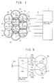
- FIG. 1 is a system constitution diagram showing a mobile communication system in the prior art disclosed, for example, in Japanese patent application laid-open No. 38940/1985.
- the mobile communication system comprises a switching station 1, base stations 2a - 2j connected to the switching station 1, a wired network 3 connecting between the switching station 1 and the base stations 2a - 2j, communication zones 4a - 4j of the base stations 2a - 2j, a crossover zone 5 where the communication zones 4a - 4j intersect each other, and a mobile station 6 moving in a service area 7 formed by the communication zones 4a - 4j.
- the base stations 2a - 2j and the mobile stations 6 have a speech radio channel (hereinafter referred to as "S-ch”) for speech, and a control radio channel (hereinafter referred to as "C-ch”) for communication of communication control signals.
- S-ch speech radio channel
- C-ch control radio channel
- These channels S-ch and C-ch are constituted by an upward channel from the mobile station 6 to the base stations 2a - 2j, and a downward channel from the base stations 2a - 2j to the mobile station 6 respectively.
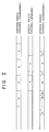
- FIG. 2 is a timing chart showing signals transmitted or received between the base stations 2a - 2j and the mobile stations 6 in the mobile communication system in such constitution. The operation will be described in an example of position registration as follows.
- the base stations 2a - 2j transmit the position registration request signals (a) continuously using the downward channel of C-ch.
- the mobile station 6 at non-speaking state waits the position registration request signals (a) from the base stations 2a - 2j.
- the position registration request signal (a) is received in the communication zone where the mobile station 6 is located at present, for example, in the downward channel of C-ch from the base station 2a of the communication zone 4a, if the base station identification code included in the position registration information signal (a) is different from that stored by the mobile station 6 at the last position registration before then, the downward channel of S-ch with an empty signal (b) transmitted from the base station 2a is detected.
- the mobile station 6 When the mobile station 6 detects a signal of the downward channel of S-ch with the empty signal (b) transmitted, the mobile station 6 transmits a position registration signal (c) in the upward channel of S-ch corresponding thereto.
- the switching station 1 performs the position registration based on the position information. From taking synchronization of the position registration signal (c) until finishing its reception, the base station 2a transmits a transmission inhibiting signal (d) to the downward channel corresponding to the upward channel of S-ch where the position registration signal (c) is transmitted. Thereby the transmission of the position registration signal (c) to the same upward channel from other mobile station 6 can be prevented.
- the collision of C-ch of these stations causes the communication failure. Even if the time difference is taken for the transmission of C-ch in order to avoid such collision of C-ch, since the base station identification code is different per each base station, the mobile station 6 even in the same communication zone responds to the position registration request signal from each base station of the communication zone. Also the mobile station 6 storing the base station identification code of the base station of some communication zone waits signals in the communication processing including the base station identification code and does not respond to signals in the same communication processing including the base station identification code from other base station in the same communication zone thereby a long time is required until the execution of the communication processing.
- FIG. 3 is a system constitution diagram of another mobile communication system in the prior art disclosed, for example, in Japanese patent application laid-open No. 147903/1977.
- the mobile communication system comprises a switching station 1, base stations 2a, 2b connected to the switching station 1, a telephone terminal 20 incorporated in the switching station 1, communication zones 4a, 4b of the base stations 2a, 2b, a mobile station 6 moving in a service area formed by the communication zones 4a, 4b, wired networks 3a, 3b connecting the base stations 2a, 2b to the switching station 1, information of signal-to-noise ratio (hereinafter referred to as "SN ratio") 17a, 17b transmitted from the base station 2a or 2b to the switching station 1, base station control signals 18a, 18b for the switching station 1 to control the base stations 2a, 2b, and speech paths 19a, 19b installed in the switching station 1 for connecting the base stations 2a, 2b to the telephone terminal 20.
- SN ratio signal-to-noise ratio
- the base stations 2a, 2b and the mobile station 6 have a speech radio channel (hereinafter referred to as "S-ch”) for speech, and a control radio channel (hereinafter referred to as "C-ch”) for communication of communication control signals.
- S-ch speech radio channel
- C-ch control radio channel
- These channels S-ch and C-ch are constituted by an upward channel from the mobile station 6 to the base stations 2a, 2b, and a downward channel from the base stations 2a, 2b to the mobile stations 2a, 2b to the mobile station 6 respectively.
- the switching station 1 detects the movement of the mobile station 6 in following manner. That is, the base station 2b always measures the SN ratio of signals from the mobile station 6, and if the measured value is the standard value or more, the SN ratio information 17b is transmitted, for example, as "l" to the switching station 1. If the mobile station 6 is moved to the communication zone 4a, the measured value of the SN ratio in the base station 2b becomes the standard value or less. Consequently, the SN ratio information 17b from the base station 2b becomes "0" for example.
- the switching station 1 Since the SN ratio information 17b becomes "0", the switching station 1 detects the movement of the mobile station 6 to the outside of the communication zone of the base station 2b, and executes changing of the channel during speech. The switching station transmits the control signal 18a to the base station 2a adjacent to the communication zone, and commands the reception of the channel S-ch with frequency used by the mobile station 6 in the communication zone 4b. The base station 2a receives the channel S-ch, and if the SN ratio is the standard value or more, the SN ratio information 17a is transmitted as "l" to the switching station 1. On receiving the information, the switching station 1 changes the speech path 19a into the speech path 19b, and realizes the speech in the mobile station 6 - the base station 2a - the switching station 1 - the telephone terminal 20, and restores the base station 2b.
- the switching station 1 Since other mobile communication system in the prior art is constituted as above described, the switching station 1 must always measure and monitor the SN ratio of the received signals from the mobile station 6 regarding all base stations 2a, 2b. Also when the movement of the mobile station between the communication zones 4a, 4b is detected, the SN ratio information must be collected regarding all base stations at the periphery of the communication zone 4b before the movement simultaneously or in sequence, in matching with the channel S-ch of frequency used by the mobile station 6 and the base station 2b within the communication zone 4b before the movement, until the communication zone 4a of the movement destination can be found. Consequently, problems exist in that large burden is applied to the processing.
- an object of the invention is to provide a mobile communication system wherein even when speech by channel S-ch between a mobile station and a base station is performed within the same communication zone the general communication service can be normally realized.
- the same communication zone is constituted by a plurality of base stations and a radio channel to be used only in the specific case is allocated to one station among the base stations, and the base station is rendered the normally receiving state and a signal on an upward channel of the radio channel to be used only in the specific case from a mobile station within the communication zone is waited, and if the general communication request signal exists in the channel, in accordance with the information included in the request, the general communication signal is transmitted using a control radio channel (hereinafter referred to as "Cn-ch”) to be used for ordinary communication control of the prescribed communication zone or a downward channel of S-ch in use.
- Cn-ch control radio channel
- the base station with the radio channel to be used only in the specific case allocated thereto is in the normally receiving state, and if a general communication request signal exists on an upward channel of the radio channel from a mobile station within the communication zone, in accordance with the information included in the general communication request signal, the switching station commands the general communication to the base stations of all communication zones or the specific communication zone, and the base station receiving the command of the general communication towards the general communication signal to the mobile station using the upward channel of Cn-ch or S-ch, thereby the mobile communication system is realized in that while ordinary service of the mobile communication system using Cn-ch and S-ch is performed for each mobile station within the corresponding communication zone, performing of service such as the general communication with higher priority can be always secured.
- Another object of the invention is to provide a mobile communication system wherein collision of C-ch or each base station of the same communication zone can be avoided when a plurality of base stations exist in the communication zone, and such useless processing can be avoided that the mobile station responds to the position registration request signals of the plural base stations in the same communication zones, and delay of the time until the execution of the prescribed communication processing can be prevented.
- a mobile communication system when a plurality of base stations constitute the same communication zone, allowance of starting the communication of a control signal by C-ch and the communication by S-ch is supplied only to one station at most among the base stations to constitute the same communication zone, and the base station supplied with the allowance is changed in sequence between the respective base stations.
- a mobile communication system is realized in that allowance of starting communication of a control signal by C-ch and of starting communication by S-ch within the same communication zone constituted by a plurality of base stations is supplied only to one station at most among the base stations within the communication zone, and the base station supplied with the allowance is changed in sequence between respective base stations within the same communication zone, thereby the collision of C-ch caused by existence of a plurality of base stations within the same communication zone can be prevented.
- a further object of the invention is to provide a mobile communication system wherein burden of processing of a switching station at the changing state of channels during speech can be reduced.
- the SN ratio measuring function of received signals is supplied not only to the base station but also to the mobile station, and the mobile station during speech always measures the SN ratio of S-ch, and on detecting the deterioration of the measured value, the mobile station is automatically transferred to C-ch and transmits the speech continuing request signal, and one of the base stations receiving the speech continuing request signal transmits the mobile station call signal to the mobile station.
- the mobile station during speech always measures the SN ratio of S-ch, and when the measured value becomes the standard value or less, the mobile station temporarily interrupts the speech on the S-ch and is automatically transferred to the speech continuing request signal, and one of the base stations receiving the speech continuing request signal transmits the mobile station call signal and changing of S-ch is performed based on the mobile station call signal, thereby the channel changing system during speech is realized in reducing the burden of the switching station at the changing state of channels during speech.
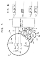
- a mobile communication system in the embodiment comprises a switching station 1, base stations 2a - 2g, a wired network 3, communication zones 4a, 4d - 4g, and a service area 7.
- Parts in FIG. 4 designated by the same reference numerals as those in FIG. 1 are the same as or similar to the parts in the prior art, and the detailed description shall be omitted.
- mobile stations 6a - 6g corresponding to the mobile station 6 shown in FIG. 1 move in the service area 7.
- the mobile communication system in the embodiment is different from the system of the prior art in that one communication zone (for example, 4a) is constituted by a plurality of (for example, three) base stations (for example, 2a - 2c).
- one base station 6d - 6g is shown for the simplification.
- FIG. 5 is a timing chart showing processing sequence of the general communication
- FIG. 6 is an explanation diagram showing format of signals transmitted or received in this case.
- the base stations 2a - 2c combined in a group constitute the same communication zone 4a, and when the communication is performed between the mobile stations 6a - 6c within the communication zone 4a, the base stations 2a - 2c have the same base station identification code imaginarily, and the communication with the mobile stations 6a - 6c by Cn-ch (channels excluding Ce-ch among C channels) is performed by stations not performing the communication on the S-ch among the base stations 2a, 2b, and the base station 2c is allocated by the radio channel (hereinafter referred to as "Ce-ch") to be used only in the specific case among the C channel and is in the normally communication state.
- Ce-ch radio channel
- the mobile station 6c transmits the general communication request signal 12a onto the Ce-ch by operation of the functional key installed on the mobile station 6c.
- the general communication request signal 12a as shown in FIG. 6(a) includes the identification code (C) of the mobile station 6c, the base station identification code Ba of the base stations 2a - 2c, and the general communication request code (A).
- the general communication request signal 12a is received by the base station 2c, and the information of the signal shown in FIG. 6(b) is transmitted to the switching station 1, and further the switching station 1 receiving the information 14a transmits the general communication command 14b also shown in FIG. 6(b) to each of the base stations 2a - 2g.
- the base station 2c receiving the general communication command 14b transmits the general communication request receiving signal 13a to the mobile station 6c.
- the general communication request signal 13a includes the general communication request receiving code (E) and the base station identification code Ba.
- each of other base stations 2a, 2b, 2d - 2g transmits the general communication signal 11a or 11b onto the channel S-ch or Cn-ch in use.
- the general communication signal 11a is transmitted from the base stations 2a, 2e, 2g during communication by S-ch shown by double line in FIG. 5 onto the S-ch
- the general communication signal 11b is transmitted from the base stations 2b, 2d, 2f not performing communication by S-ch shown by single line in FIG.
- the general communication signals 11a, 11b as shown in FIG. 6(d) include the base station identification code Bn (n: a, d, e, f or g) of each communication zone.
- Bn base station identification code
- Each of the mobile stations 6a, 6b, 6d - 6g receiving the general communication signals 11a, 11b rumbles a buzzer provided therewith and informs a user of the general communication. The buzzer keeps rumbling unless the user stops it.
- the communication after stopping the rumbling of the buzzer may be one-directional speech from one mobile station transmitting request of general communication to other mobile station or teleconference communication between these mobile stations.
- the general communication is performed for all mobile stations 6a - 6g within the service area 7, the mobile stations 6a - 6g may be divided into groups and the general communication may be performed only for the specific group.
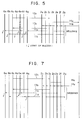
- FIG. 7 is a sequence chart showing the processing sequence of the general communication in such embodiment
- FIG. 8 is an explanation diagram showing format of signals transmitted or received then.
- the mobile stations 6a, 6c, 6e, 6g are made the first group
- the mobile stations 6b, 6d, 6f are made the second group
- each group is supplied with mobile station group identification code FN1 or FN2 peculiar thereto respectively.
- Each of the mobile stations 6a - 6g stores the mobile station group identification code FN1 or FN2 of the group to which each station belongs.
- the general communication request signal 12b with the mobile station group identification code FN1 shown in FIG. 8(a) added thereto is transmitted onto the Ce-ch by operation of a functional key provided on the mobile station 6c and subsequently by operation of a mobile station group identification code transmission key.
- the general communication request signal 12b is received by the base station 2c and the information 14c of the signal is transmitted to the switching station 1, which transmits the general communication command 14d to each of the base stations 2a - 2g.
- the mobile station group identification code FN1 is added also to the information 14c and the general communication command 14d as shown in FIG. 8(b).
- the base station 2c On receiving the general communication command 14d, the base station 2c transmits the general communication request receiving signal 13b with the mobile station group identification code FN1 added thereto as shown in FIG. 8(c) to the mobile station 6c.
- other base stations 2a, 2b, 2d - 2g transmit the general communication signal 11c or 11d with the mobile station group identification code FN1 added thereto as shown in FIG. 8(d) onto the channel S-ch or Cn-ch in use.
- Each of the mobile stations 6a, 6b, 6d - 6g receiving the general communication signals 11c, 11d rumbles a buzzer and informs a user of the general communication, only when the mobile station group identification code FN1 on the general communication signals 11c, 11d is coincident with the mobile station group identification code FN1 or FN2 stored in each mobile station. Consequently, the buzzer rumbles in the mobile stations 6a, 6e, 6g included in the same group as that of the mobile station 6c.
- the switching station 1 may have the mobile station group identification code FN1 or FN2 and the information of the mobile stations included in the group and the communication to each mobile station of the group may be performed by processing of the switching station 1.
- the embodiment has been described where the mobile stations 6a - 6g are divided into groups.
- the communication zones 4a, 4d - 4g may be divided into groups and the general communication may be performed only to the specific group.
- FIG. 9 is a sequence chart showing processing sequence of the general communication in such embodiment
- FIG. 10 is an explanation diagram showing format of signals transmitted or received then.
- the communication zones 4a, 4d are made the first group and the communication zones 4e - 4g are made the second group, and each group is allocated with the base station group identification code HN1 or HN2 peculiar thereto respectively.
- Each of the base stations 2a - 2g within the communication zones 4a, 4d - 4g stores the base station group identification code HN1 or HN2 of the group to which the communication zones 4a, 4d - 4g belong.
- the general communication request signal 12c with the base station group identification code HN1 shown in FIG. 10(a) added thereto is transmitted onto the Ce-ch by operation of a functional key provided on the mobile station 6c and subsequently by operation of a mobile station group identification code transmission key.
- the general communication request signal 12c is received by the base station 2c and the information 14e of the signal is transmitted to the switching station 1, which transmits the general communication command 14f to each of the base stations 2a - 2g.
- the base station group identification code HN1 is added to the information 14e and the general communication command 14f as shown in FIG. 10(b).
- the base station 2c On receiving the general communication command 14f, the base station 2c transmits the general communication request receiving signal 13c with the base station group identification code HN1 added thereto as shown in FIG. 10(c) to the mobile station 6c.
- other base stations 2a, 2b, 2d - 2g transmit the general communication signals 11a, 11b shown in FIG. 10(d), only when the base station group identification code HN1 on the general communication command 14f is coincident with the base station identification information HN1 or HN2 stored in each base station. Consequently, the general communication signals 11a, 11b are transmitted from the base stations 2a, 2b, 2d having the identification information HN1.
- Each of the mobile stations 6a - 6d moving in the communication zones 4a, 4b receiving the general communication signals 11a, 11b rumbles a buzzer and informs a user of the general communication.
- the switching station 1 may have the base station group identification code HN1 or HN2 and the information of the base stations included in the group, and the general communication command 14f may be transmitted to each of the base stations of the group by processing of the switching station 1 and the general communication may be applied to the communication zone. Further, the communication zone of the destination station may be assigned not only from the base station previously set but also from the mobile station at the start state of the general communication.
- a plurality of base stations are arranged in one communication zone, and one of the base stations is made the normally receiving state and the radio channel to be used only in the specific case is allocated to the base station and used for the communication of the emergency signal such as general communication request, thereby the mobile communication system can be obtained in that the emergency signal does not collide with a signal for ordinary speech control and the general communication of high accuracy can be performed.
- FIG. 11 is a system constitution diagram showing a mobile communication system in another embodiment of the invention.
- the mobile communication system comprises a switching station 1, a wired network 3, communication zones 4a - 4j, a crossover zone 5, and a mobile station 6.
- Parts in FIG. 11 designated by the same reference numerals as those in FIG. 1 are the same as or similar to the parts in the prior art, and the detailed description shall be omitted.
- Numerals 27a - 27j designate base station groups each comprising plural base stations or single base station, and the communication zones 4a - 4j are constituted by these base station groups 27a - 27j.
- FIG. 12 is a block diagram showing constitution of the base station group 27a shown in FIG. 11.
- three base stations 2a - 2c form the base station group 27a, and are connected through the wired network 3 to the switching station 1 respectively.
- Mobile stations 6a - 6d are within the communication zone 4a constituted by the base station group 27a, and correspond to the mobile station 6 shown in FIG. 11.
- FIG. 13 is a timing chart showing an example of use allowance of C-ch and movement of start allowance of speech by S-ch.
- numeral 110 designates use allowance of C-ch and start allowance of speech by S-ch (hereinafter referred to as "C-ch, S-ch allocation")
- numeral 111 designates communication between the base stations 2a - 2c and the mobile stations 6a - 6d
- numeral 112 designates movement of the C-ch
- S-ch allocation designates correspondence of speech between the base stations 2a - 2c and the mobile stations 6a - 6d in broken line.
- the priority of the C-ch, S-ch allocation is highest at the base station 2a, and set in the order of the base station 2b and the base station 2c.
- the communication 111 on the S-ch is started between the base stations 2a - 2c supplied with the C-ch, S-ch allocation until then and the mobile stations 6a - 6d, the movement 112 of the C-ch, S-ch allocation is always performed for the station having the highest priority among the base stations 2a - 2c which do not perform the communication 111 on the S-ch.
- the movement of the C-ch, S-ch allocation is performed only when the communication does not exist on the C-ch.
- the C-ch, S-ch allocation means that communication of a control signal with the mobile stations 6a - 6d is performed using the C-ch, and that when the call originating from new mobile stations 6a - 6d is performed or the call incoming to new mobile stations 6a - 6d is performed, allowance of transferring to the communication on the S-ch between the base stations 2a - 2c and the mobile stations 6a - 6d is supplied to the base stations 2a - 2c.
- the channel S-ch is selected so that the interference can not be easily produced between the base stations 2a - 2c and between the base station groups 27a - 27j.
- FIG. 14 is a flow chart showing the above-mentioned control procedure. That is, if new call originating is detected at step ST1, S-ch being not in use in each of the base stations 2a - 2c is detected in accordance with the priority at steps ST2 - ST4. If the S-ch being not in use is detected in any of the base stations 2a - 2c, the C-ch, S-ch allocation is performed to the base stations 2a - 2c at steps ST5 - ST7. If the S-ch being not in use does not exist even in the base station 2c, the C-ch, S-ch allocation is not performed to any of the base stations 2a - 2c (step ST8), and the processing is finished. Also if it is detected that the call without C-ch, S-ch allocation is not finished at steps ST9, ST10, the process is returned to step ST2, and the detection of the S-ch being not in use in the base stations 2a - 2c is performed again.
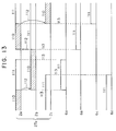
- FIG. 15 is a timing chart showing an example of timing of the position registration executed by the base stations 2a - 2c and the mobile station 6a.
- numeral 121a designates a position registration request signal of the base station group 27a
- numeral 121b designates a position registration request signal of the adjacent base location group
- numeral 122 designates a position registration signal of the mobile station 6a.
- the C-ch, S-ch allocation is performed for one station at most among the base stations 2a - 2c forming the base station group 27a.
- One station among the base stations 2a - 2c supplied with the C-ch, S-ch allocation transmits the position registration request signal 121a to the mobile station 6a in the period of T2 using the downward channel of C-ch.
- the base station groups 27b, 27c, 27d of the communication zones 4b, 4c, 4d having the crossover zone 5 commonly with the communication zone 4a transmit the position registration request signal 121b in the time shifting as shown in FIG. 15.
- the mobile station 6a newly enters the communication zone 4a of the base station group 27a at the time Ta of FIG. 15.
- the position registration request signal 121a includes the request signal (P) and the base station group identification signal (Q), and the base station group identification signal (Q) among these signals is common between the base stations 2a - 2c to constitute the base station group 27a.
- the mobile station 6a On receiving the position registration request signal 121a, the mobile station 6a returns the position registration signal 122 to the position registration request signal 121a received first from the time of Ta.
- the position registration signal 122 includes the registration signal (R), the mobile station identification code (S) and the base station group identification code (Q).
- the mobile station 6a stores the base station group identification code (Q), and next returns the position registration signal 122 only when the base station group identification code (Q) at receiving the position registration request signal 121a is different from the base station group identification code (Q) at previously returning the registration signal 122b.
- FIG. 16 is a flow chart showing the control procedure of the mobile station 6a during the position registration. That is, if the mobile station 6a receives the position registration request signal 121a (step ST11), the base station identification code (Q) in the position registration request signal 121a and the stored base station identification code (Q) are compared (step ST12). As a result, if both are coincident, the processing is finished directly. If both are not coincident, the position registration signal 122 is transmitted and the stored base station identification code (Q) is updated (step ST13), and then the processing is finished.
- FIG. 17 is an explanation diagram showing an example of constitution of a memory storing the information of the position registration of the mobile stations 6a - 6d.
- numerals 150a - 150d designate addresses allocated to each of the mobile stations 6a - 6d, and corresponding to the addresses 150a - 150d, data 151a - 151d are written so as to indicate in which position of the communication zones 4a - 4j exists each of the mobile stations 6a - 6d.
- the data structure is not limited to that as above described, but other data structure suitable for the applied device sort may be taken.
- FIG. 18 is an explanation diagram showing a display example of the position indicator indicating the information of the position registration.
- the position information of each of the mobile stations 6a - 6d is obtained, and corresponding one among the light emission diodes 152a, 152b, ... is lit.
- the display method is not limited to that as above described, but method using a cathode ray tube display, a liquid crystal display or the like and being suitable for the applied device sort may be adopted.
- FIG. 19 is a sequence chart showing an example of the sequence.
- numeral 141 designates a call incoming signal from the base station 2a to the mobile station 6a
- numeral 142 designates a call incoming response signal from the mobile station 6b to the base station 2a
- numeral 143 designates speech and communication on the S-ch between the base station 2a and the mobile station 6a.
- Numeral 144 designates C-ch, S-ch allocation release signal from the base station 2a to the switching station 1
- numeral 145 designates C-ch
- numeral 146 designates a speech confirmation signal from the base station 2a to the mobile station 6a
- Numeral 147 designates a speech confirmation response signal from the mobile station 6a to the base station 2a
- numeral 148 designates a speech end signal in similar state.
- each of the signals 141 - 148 except for the C-ch, S-ch allocation release signal 144 and the C-ch, S-ch allocation signal 145 includes a base station group identification code peculiar to the base station group 27a.
- the call incoming response signal 142, the speech confirmation response signal 147 and the speech end signal 148 include a mobile station identification code.
- the base station 2a transmits the call incoming signal 141 on C-ch to the mobile station 6a. On receiving this signal, the mobile station 6a returns the call incoming response signal 142 to the base station 2a, thereby both stations enter the speech communication 143 on the S-ch. During the speech communication 143 on the S-ch, such sequence is performed on the S-ch that the base station 2a transmits the speech confirmation signal 146 to the mobile station 6a periodically and the mobile station 6a returns the speech confirmation response signal 147. Finally, the mobile station 6a transmits the speech end signal 148 to the base station 2a, and then signals on the C-ch are transmitted or received between the mobile station 6a and the base station 2b.
- the C-ch, S-ch allocation release signal 144 and the C-ch, S-ch allocation signal 145 are in series of sequence between the base stations 2a, 2b and the switching station 1 so as to move the C-ch, S-ch allocation from the base station 2a to the base station 2b.
- the mobile communication system can be obtained in that the matching of the processing is scarcely deteriorated due to the number of the base stations within the base station group.
- This sequence can be applied not only to sequence from the call incoming to the mobile station until the speech end as above described, but also to any sequence capable of transmitting or receiving the base station group identification code between the base station and the mobile station.
- the C-ch is one channel within one base station group
- the C-ch may be plural channels which are changed one by one or simultaneously.
- the prescribed S-ch can be used as substitute for the C-ch in the entirely same function.
- the use allowance of C-ch and the start allowance of speech of S-ch are not supplied to the same base station, but may be supplied in one per each base station.
- the selection of the base stations to obtain such allowance may be performed not only by the priority previously set, but the selection may be performed in accordance with random numbers or the selection order may be circulated, and similar effects to the above-mentioned embodiment can be obtained in any case.
- allowance of communication of a control signal by C-ch and allowance of start of speech by S-ch within the same communication zone constituted by a plurality of base stations are supplied only to one base station at most within the communication zone, and the allowance is changed in sequence between respective base stations to constitute the communication zone, thereby the mobile communication system can be obtained in that useless position response due to difference between the base station identification code stored in the mobile station and the base station identification code included in signals on the downward channel of C-ch or non-response to signals for the communication processing can be prevented, and the collision of C-ch caused by the plurality of base stations existing within the same communication zone can be prevented.
- FIG. 20 is a system constitution diagram showing a mobile communication in still another embodiment of the invention.
- the mobile communication system comprises a switching station 1, a telephone terminal 20, communication zones 4a - 4d, and wired networks 3a - 3d. Parts in FIG. 20 designated by the same reference numerals as those in FIG. 3 are the same as or similar to the parts in the prior art.
- the mobile communication system also comprises a crossover zone 5 where the communication zones 4a - 4d intersect each other, base stations 211a - 211d to constitute the communication zones 4a - 4d, and a mobile station 212 moving in a service area formed by the communication zones 4a - 4d.
- FIG. 21 is a schematic constitution diagram of the base stations 211a - 211d showing only a relevant part to the invention
- FIG. 22 is a schematic constitution diagram of the mobile station 212 showing only a relevant part to the invention.
- SN ratio measuring circuits 213a, 213b for measuring the SN ratio of the received signal are disposed in the base stations 211a - 211d or the mobile station 212.
- Numerals 214a, 214b designate transmitting/receiving circuits including a control section for processing the SN ratio measured by the SN ratio measuring circuit 213a or 213b.
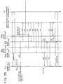
- FIG. 23 is a sequence chart showing signal sequence at the channel changing during speech.
- the mobile station 212 in the communication zone 4a performing the communication on the S-ch with the base station 211a is moved through the crossover zone 5 to the communication zone 4b of the base station 211b as follows.
- the mobile station 212 during speech on the S-ch always measures the SN ratio of the received signal from the base station 211 by the SN ratio measuring circuit 213b. As the mobile station 212 is moved from the communication zone 4b to the crossover zone 5, the measured value of the SN ratio by the SN ratio measuring circuit 213b is deteriorated. If the measured value of the SN ratio becomes less than the standard value at the time 2A shown in FIG. 23, this is detected by the control section of the transmitting/receiving circuit 214b in the mobile station 212. Then the speech on the S-ch is immediately interrupted, and the process is transferred to the communication by the C-ch and the speech continuing request signal 2B requesting the speech continuing is transmitted onto the C-ch.
- the speech continuing request signal 2B includes the mobile station identification code of the mobile station 212.
- the speech continuing request signal 2B is received in each of the base stations 211b - 211d, and the SN ratio is measured in the SN ratio measuring circuit 213a.
- the measured value of the SN ratio is processed by the control section in the transmitting/receiving circuit 214, and the continuing receiving signal 2C including the SN ratio information of the obtained receiving signal and the mobile station identification code is produced and transmitted to the switching station 1.
- the switching station 1 analyzes the SN information included in the received continuing receiving signal 2C, and selects the base station indicating the value satisfying the standard value, for example, the base station 211b and transmits a base station selecting signal 2D to the base station 211b. In this case, if there are a plurality of base stations indicating the value satisfying the standard value, one station is selected among these base stations at random or in accordance with the priority previously set.
- a reset signal 2E is transmitted from the switching station 1 to each of the base stations 211c, 211d which are not selected, and each of the base stations 211c, 211d receiving the signal is reset to the original state and returns a reset receiving signal 2F to the switching station 2F.
- the base station 211b receiving the base station selecting signal 2D transmits a mobile station call signal 2G including the mobile station identification code and the empty S-ch information to the mobile station 212, and then the base station 211b and the mobile station 212 are transferred to the communication on the assigned S-ch.
- the mobile station 212 receiving the mobile station call signal 2G transmits a connection confirmation signal 2H including the mobile station identification code and the base station identification code of the base station 211b
- the base station 211b receiving the connection confirmation signal 2H returns a connection confirmation response signal 2I to the mobile station 212 and transmits a speech path setting request signal 2J including the mobile station identification code to the switching station 1. And then the base station 211a is reset.
- the switching station 1 receiving the speech path setting request signal 2J from the base station 211b sets a speech path between the base station 211b and the telephone terminal 20, and the mobile station 212 enters the speech state with the telephone terminal 20.
- the speech continuing request signal 2B may be received also by the base station 211a, but the reception of the signal 2B in this case shall be ignored.
- the base station selecting signal 2D is supplied to the base station having the SN ratio information included in the continuing receiving signal 2C indicating the value satisfying the standard value.
- the base station selecting signal 2D may be supplied to the base station where the continuing receiving signal 2C is first informed.
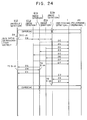
- FIG. 24 is a sequence chart showing signal sequence at the channel changing during speech in such embodiment.
- FIG. 24 is the same as FIG. 23 in that the base stations 211b - 211d receiving the speech continuing request signal 2B from the mobile station 212 transmit the continuing receiving signal 2C.
- the continuing receiving signal 2C is first transmitted by the base station 211c, and then transmitted by the base station 211d, the base station 211b in sequence.
- the switching station selects the base station 211c where the signal is first transmitted, and transmits the base station selecting signal 2D to the base station 211c.
- the reset signal 2E is transmitted to the base stations 211b, 211d which are not selected, thereby these stations are reset to the original state.
- the mobile station 212 enters the speech state with the telephone terminal 20 and the base station 211a is reset.
- the SN ratio measuring circuit 213a of each of the base stations 211a - 211d during speech monitors only the periodic SN ratio without relation to the channel changing, it may be omitted if not necessary.
- the base stations 211a - 211d as the transmission object of the base station selecting signal 2D are not limited to that first informing the continuing receiving signal 2C to the switching station 1, but may be arbitrary.
- the base station selecting signal may be supplied to the base station which receives the speech continuing request signal from the mobile station in the best SN ratio.
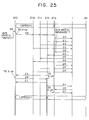
- FIG. 25 is a sequence chart showing signal sequence at the channel changing during speech in such embodiment.
- FIG. 25 is the same as FIG. 23 in that each base station receives the speech continuing request signal B from the mobile station.
- each of the base stations 211a - 211d including the base station 211a during speech at present if the speech continuing request signal 2B is received, the SN ratio of the received signal is measured in the respective SN ratio measuring circuit 213, and the measured value is processed in the control section of the transmitting/receiving circuit 214a.
- each of the base stations 211a - 211d generates the mobile station identification code of the mobile station 212 transmitting the speech continuing request signal 2B and the continuing receiving signal 2C including the SN ratio information of the received signal, and transmits the signals from the transmitting/receiving circuit 214a to the switching station 1.
- the switching station 1 On receiving the continuing receiving signal 2C from each of the base stations 211b - 211d, the switching station 1 analyzes the SN ratio information included in the continuing receiving signal 2C, and selects the base station having the best value, for example, the base station 211b and transmits a base station selecting signal 2D to the base station 211b. Also the switching station 1 transmits a reset signal 2E to the base stations 211a, 211c, 211d which are not selected, and each of the base stations 211a, 211c, 211d receiving the signal 2E is reset to the original state and returns a reset receiving signal 2F to the switching station 1.
- the base station 211b receiving the base station selecting signal 2D transmits a mobile station call signal 2G including the mobile station identification code and the empty S-ch information to the mobile station 212. And then in similar manner to FIG. 23, through the selected base station 211c and the speech path set between the base station 211c and the telephone terminal 20 in the switching station 1, the mobile station 212 enters the speech state with the telephone terminal 20.
- the mobile station can perform speech using S-ch with the base station in the best communication state and the more stable and better speech quality can be obtained.
- the speech path may be confirmed on the S-ch after changing the S-ch during speech, and if it can not be confirmed, the state before the changing may be restored.
- FIG. 26 is a sequence chart showing signal sequence at the channel changing during speech in such embodiment.
- FIG. 26 is the same as FIG. 23 in that the base station 211b transmits the mobile station call signal 2G to the mobile station 212.
- the mobile station 212 receives a mobile station call signal 2G including the mobile station identification code of the mobile station 212 and the empty S-ch information transmitted by the base station 211b, and then the mobile station 212 is transferred to new communication on S-ch.
- the mobile station 212 receiving the mobile station call signal 2G transmits a connection confirmation signal 2H including the mobile station identification code and the base station identification signal of the base station 211b, but it is assumed that the connection confirmation signal 2H is not received in the base station 211 by any cause.
- the mobile station 212 waits a connection confirmation response signal 2J from the base station 211b for the prescribed time T11 after transmitting the connection confirmation signal 2H. In this case, since the connection confirmation response signal 2J can not be received for the prescribed time T11, the S-ch is returned to the channel before the time 2A. Also the base station 211b waits the connection confirmation signal 2H from the mobile station 212 for the prescribed time T22 after transmitting the mobile station call signal 2G, but since the connection confirmation signal 2H can not be received for the prescribed time T22, as reset request signal 2K is transmitted to the switching station 1. The switching station 1 receiving the reset request signal 2K resets the base station 211b, thereby the speech between the mobile station 212 and the base station 211b is restored.
- the communication destination of the mobile station is the telephone terminal, it may be other terminal connected through the mobile station or public network, or the direction of transmission and reception of the connection confirmation signal and the connection confirmation response signal may be made the reverse direction.
- the base station number within the same communication zone is one and only one mobile station is shown, the number of the base stations and the mobile stations may be arbitrary and the same communication zone may be constituted by a plurality of base stations. Similar effects to the embodiments can be obtained in any of the modifications.
- the mobile station also has the SN ratio measuring function of received signals and always measures the SN ratio of S-ch during speech, and if the deterioration of the SN ratio is detected, speech on the S-ch is temporarily interrupted and transferring to the C-ch is automatically performed and a speech continuing request signal is transmitted and the S-ch is changed by the mobile station call signal transmitted by one base station receiving the speech continuing request signal, thereby the SN ratio of received signals in the base station from the mobile station need not be always measured or monitored by the switching station, and even if the SN ratio information of all base stations in the adjacent communication zone is not collected in matching with the S-ch of frequency used by the communication zone before the movement, the moving destination of the mobile station can be discriminated, thus the channel changing system during speech can be obtained in that the load of the switching station at the channel changing during speech can be significantly reduced.
Landscapes
- Engineering & Computer Science (AREA)
- Computer Networks & Wireless Communication (AREA)
- Signal Processing (AREA)
- Mobile Radio Communication Systems (AREA)
Abstract
Description
- The present invention relates to a mobile communication system constituted by a switching station, base stations connected to the switching station, and a plurality of mobile stations moving in a service area formed by communication zones due to the base stations.
- FIG. 1 is a system constitution diagram showing a mobile communication system in the prior art disclosed, for example, in Japanese patent application laid-open No. 38940/1985. In FIG. 1, the mobile communication system comprises a
switching station 1,base stations 2a - 2j connected to theswitching station 1, awired network 3 connecting between theswitching station 1 and thebase stations 2a - 2j,communication zones 4a - 4j of thebase stations 2a - 2j, acrossover zone 5 where thecommunication zones 4a - 4j intersect each other, and amobile station 6 moving in aservice area 7 formed by thecommunication zones 4a - 4j. - The
base stations 2a - 2j and themobile stations 6 have a speech radio channel (hereinafter referred to as "S-ch") for speech, and a control radio channel (hereinafter referred to as "C-ch") for communication of communication control signals. These channels S-ch and C-ch are constituted by an upward channel from themobile station 6 to thebase stations 2a - 2j, and a downward channel from thebase stations 2a - 2j to themobile station 6 respectively. - Next, operation will be described. FIG. 2 is a timing chart showing signals transmitted or received between the
base stations 2a - 2j and themobile stations 6 in the mobile communication system in such constitution. The operation will be described in an example of position registration as follows. - When the position information of the
mobile station 6 becomes necessary, thebase stations 2a - 2j transmit the position registration request signals (a) continuously using the downward channel of C-ch. Themobile station 6 at non-speaking state waits the position registration request signals (a) from thebase stations 2a - 2j. When the position registration request signal (a) is received in the communication zone where themobile station 6 is located at present, for example, in the downward channel of C-ch from thebase station 2a of thecommunication zone 4a, if the base station identification code included in the position registration information signal (a) is different from that stored by themobile station 6 at the last position registration before then, the downward channel of S-ch with an empty signal (b) transmitted from thebase station 2a is detected. - When the
mobile station 6 detects a signal of the downward channel of S-ch with the empty signal (b) transmitted, themobile station 6 transmits a position registration signal (c) in the upward channel of S-ch corresponding thereto. Theswitching station 1 performs the position registration based on the position information. From taking synchronization of the position registration signal (c) until finishing its reception, thebase station 2a transmits a transmission inhibiting signal (d) to the downward channel corresponding to the upward channel of S-ch where the position registration signal (c) is transmitted. Thereby the transmission of the position registration signal (c) to the same upward channel from othermobile station 6 can be prevented. - In the mobile communication system in the prior art constituted as above described, since only one
base station 2a - 2j is installed at thesame communication zone 4a - 4j, even if the emergency state occurs during use of the channel S-ch by thebase station 2a - 2j, the general communication cannot be performed from themobile station 6 within thecorresponding communication zone 4a - 4j. Also even if themobile station 6 intends to perform the general communication using the channel C-ch, the general communication cannot be normally performed due to collision of the channel C-ch with other mobile station or other base station. - When the
communication zones 4a - 4j are constituted simply by a plurality of base stations, the collision of C-ch of these stations causes the communication failure. Even if the time difference is taken for the transmission of C-ch in order to avoid such collision of C-ch, since the base station identification code is different per each base station, themobile station 6 even in the same communication zone responds to the position registration request signal from each base station of the communication zone. Also themobile station 6 storing the base station identification code of the base station of some communication zone waits signals in the communication processing including the base station identification code and does not respond to signals in the same communication processing including the base station identification code from other base station in the same communication zone thereby a long time is required until the execution of the communication processing. - FIG. 3 is a system constitution diagram of another mobile communication system in the prior art disclosed, for example, in Japanese patent application laid-open No. 147903/1977. In FIG. 3, the mobile communication system comprises a
switching station 1,base stations switching station 1, atelephone terminal 20 incorporated in theswitching station 1,communication zones base stations mobile station 6 moving in a service area formed by thecommunication zones wired networks base stations switching station 1, information of signal-to-noise ratio (hereinafter referred to as "SN ratio") 17a, 17b transmitted from thebase station switching station 1, base station control signals 18a, 18b for theswitching station 1 to control thebase stations speech paths 19a, 19b installed in theswitching station 1 for connecting thebase stations telephone terminal 20. - The
base stations mobile station 6 have a speech radio channel (hereinafter referred to as "S-ch") for speech, and a control radio channel (hereinafter referred to as "C-ch") for communication of communication control signals. These channels S-ch and C-ch are constituted by an upward channel from themobile station 6 to thebase stations base stations mobile stations mobile station 6 respectively. - Next, operation will be described. Assume now that speech exists between the
telephone terminal 20 and themobile station 6 in thecommunication zone 4b through thebase station 2b. - Then the
switching station 1 detects the movement of themobile station 6 in following manner. That is, thebase station 2b always measures the SN ratio of signals from themobile station 6, and if the measured value is the standard value or more, theSN ratio information 17b is transmitted, for example, as "l" to theswitching station 1. If themobile station 6 is moved to thecommunication zone 4a, the measured value of the SN ratio in thebase station 2b becomes the standard value or less. Consequently, theSN ratio information 17b from thebase station 2b becomes "0" for example. - Since the
SN ratio information 17b becomes "0", theswitching station 1 detects the movement of themobile station 6 to the outside of the communication zone of thebase station 2b, and executes changing of the channel during speech. The switching station transmits the control signal 18a to thebase station 2a adjacent to the communication zone, and commands the reception of the channel S-ch with frequency used by themobile station 6 in thecommunication zone 4b. Thebase station 2a receives the channel S-ch, and if the SN ratio is the standard value or more, the SN ratio information 17a is transmitted as "l" to theswitching station 1. On receiving the information, theswitching station 1 changes the speech path 19a into thespeech path 19b, and realizes the speech in the mobile station 6 - thebase station 2a - the switching station 1 - thetelephone terminal 20, and restores thebase station 2b. - Since other mobile communication system in the prior art is constituted as above described, the
switching station 1 must always measure and monitor the SN ratio of the received signals from themobile station 6 regarding allbase stations communication zones communication zone 4b before the movement simultaneously or in sequence, in matching with the channel S-ch of frequency used by themobile station 6 and thebase station 2b within thecommunication zone 4b before the movement, until thecommunication zone 4a of the movement destination can be found. Consequently, problems exist in that large burden is applied to the processing. - In view of the above-mentioned problems in the prior art, an object of the invention is to provide a mobile communication system wherein even when speech by channel S-ch between a mobile station and a base station is performed within the same communication zone the general communication service can be normally realized.
- In order to attain the foregoing object, in a mobile communication system according to the invention, the same communication zone is constituted by a plurality of base stations and a radio channel to be used only in the specific case is allocated to one station among the base stations, and the base station is rendered the normally receiving state and a signal on an upward channel of the radio channel to be used only in the specific case from a mobile station within the communication zone is waited, and if the general communication request signal exists in the channel, in accordance with the information included in the request, the general communication signal is transmitted using a control radio channel (hereinafter referred to as "Cn-ch") to be used for ordinary communication control of the prescribed communication zone or a downward channel of S-ch in use.
- The base station with the radio channel to be used only in the specific case allocated thereto is in the normally receiving state, and if a general communication request signal exists on an upward channel of the radio channel from a mobile station within the communication zone, in accordance with the information included in the general communication request signal, the switching station commands the general communication to the base stations of all communication zones or the specific communication zone, and the base station receiving the command of the general communication towards the general communication signal to the mobile station using the upward channel of Cn-ch or S-ch, thereby the mobile communication system is realized in that while ordinary service of the mobile communication system using Cn-ch and S-ch is performed for each mobile station within the corresponding communication zone, performing of service such as the general communication with higher priority can be always secured.
- Another object of the invention is to provide a mobile communication system wherein collision of C-ch or each base station of the same communication zone can be avoided when a plurality of base stations exist in the communication zone, and such useless processing can be avoided that the mobile station responds to the position registration request signals of the plural base stations in the same communication zones, and delay of the time until the execution of the prescribed communication processing can be prevented.
- In order to attain the foregoing object, in a mobile communication system according to the invention, when a plurality of base stations constitute the same communication zone, allowance of starting the communication of a control signal by C-ch and the communication by S-ch is supplied only to one station at most among the base stations to constitute the same communication zone, and the base station supplied with the allowance is changed in sequence between the respective base stations.
- A mobile communication system is realized in that allowance of starting communication of a control signal by C-ch and of starting communication by S-ch within the same communication zone constituted by a plurality of base stations is supplied only to one station at most among the base stations within the communication zone, and the base station supplied with the allowance is changed in sequence between respective base stations within the same communication zone, thereby the collision of C-ch caused by existence of a plurality of base stations within the same communication zone can be prevented.
- A further object of the invention is to provide a mobile communication system wherein burden of processing of a switching station at the changing state of channels during speech can be reduced.
- In order to attain the foregoing object, in a mobile communication system according to the invention, the SN ratio measuring function of received signals is supplied not only to the base station but also to the mobile station, and the mobile station during speech always measures the SN ratio of S-ch, and on detecting the deterioration of the measured value, the mobile station is automatically transferred to C-ch and transmits the speech continuing request signal, and one of the base stations receiving the speech continuing request signal transmits the mobile station call signal to the mobile station.
- The mobile station during speech always measures the SN ratio of S-ch, and when the measured value becomes the standard value or less, the mobile station temporarily interrupts the speech on the S-ch and is automatically transferred to the speech continuing request signal, and one of the base stations receiving the speech continuing request signal transmits the mobile station call signal and changing of S-ch is performed based on the mobile station call signal, thereby the channel changing system during speech is realized in reducing the burden of the switching station at the changing state of channels during speech.
-
- FIG. 1 is a system constitution diagram showing a mobile communication system in the prior art;
- FIG. 2 is a timing chart showing transmission timing of signals transmitted or received in the system of FIG. 1;
- FIG. 3 is a system constitution diagram showing another mobile communication system in the prior art;
- FIG. 4 is a system constitution diagram showing a mobile communication system in an embodiment of the invention;
- FIG. 5 is a sequence chart showing processing sequence of general communication in the system of FIG. 4;
- FIG. 6 is an explanation diagram showing format of signals transmitted or received in the processing of FIG. 5;
- FIG. 7 is a sequence chart showing processing sequence of other general communication in the system of FIG. 4;
- FIG. 8 is an explanation diagram showing format of signals transmitted or received in the processing of FIG. 7;
- FIG. 9 is a sequence chart showing processing sequence of further general communication in the system of FIG. 4;
- FIG. 10 is an explanation diagram showing format of signals transmitted or received in the processing of FIG. 9;
- FIG. 11 is a system constitution diagram showing a mobile communication system in another embodiment of the invention;
- FIG. 12 is a constitution diagram showing constitution of a base station group of FIG. 11;
- FIG. 13 is a timing chart showing allocation changing of C-ch and S-ch;
- FIG. 14 is a flow chart showing processing procedure of allocation changing;
- FIG. 15 is a timing chart showing transmission timing of signals transmitted or received during position registration;
- FIG. 16 is a flow chart showing processing procedure regarding a position registration signal;
- FIG. 17 is an explanation diagram showing an example of constitution of a memory storing position registration information;
- FIG. 18 is an explanation diagram showing a display example in a position display device;
- FIG. 19 is a sequence chart showing sequence from calling to speech end between a base station and a mobile station;
- FIG. 20 is a system constitution diagram showing a mobile communication system in still another embodiment of the invention;
- FIG. 21 is a block diagram showing schematic constitution of a basic station;
- FIG. 22 is a block diagram showing schematic constitution of a mobile station; and
- FIGs. 23 - 26 are sequence diagrams showing signal sequence at channel changing during speech.
- An embodiment of the invention will be described referring to the accompanying drawings as follows. In FIG. 4, a mobile communication system in the embodiment comprises a switching
station 1,base stations 2a - 2g, awired network 3,communication zones service area 7. Parts in FIG. 4 designated by the same reference numerals as those in FIG. 1 are the same as or similar to the parts in the prior art, and the detailed description shall be omitted. Alsomobile stations 6a - 6g corresponding to themobile station 6 shown in FIG. 1 move in theservice area 7. - The mobile communication system in the embodiment is different from the system of the prior art in that one communication zone (for example, 4a) is constituted by a plurality of (for example, three) base stations (for example, 2a - 2c). In FIG. 4, regarding each of the
communication zones 4d - 4g, onebase station 6d - 6g only are shown for the simplification. - Next, operation will be described. In this connection, FIG. 5 is a timing chart showing processing sequence of the general communication, and FIG. 6 is an explanation diagram showing format of signals transmitted or received in this case.
- In FIG. 4, the
base stations 2a - 2c combined in a group constitute thesame communication zone 4a, and when the communication is performed between themobile stations 6a - 6c within thecommunication zone 4a, thebase stations 2a - 2c have the same base station identification code imaginarily, and the communication with themobile stations 6a - 6c by Cn-ch (channels excluding Ce-ch among C channels) is performed by stations not performing the communication on the S-ch among thebase stations base station 2c is allocated by the radio channel (hereinafter referred to as "Ce-ch") to be used only in the specific case among the C channel and is in the normally communication state. In this case, thebase station 2a and themobile station 6a perform the communication on the S-ch, and the Cn-ch is allocated to thebase station 2b. Similar state applies also toother communication zones 4d - 4g. - In this case, it is assumed that the
mobile station 6c transmits the general communication request signal 12a onto the Ce-ch by operation of the functional key installed on themobile station 6c. The general communication request signal 12a as shown in FIG. 6(a) includes the identification code (C) of themobile station 6c, the base station identification code Ba of thebase stations 2a - 2c, and the general communication request code (A). The general communication request signal 12a is received by thebase station 2c, and the information of the signal shown in FIG. 6(b) is transmitted to the switchingstation 1, and further the switchingstation 1 receiving theinformation 14a transmits the general communication command 14b also shown in FIG. 6(b) to each of thebase stations 2a - 2g. - The
base station 2c receiving the general communication command 14b transmits the general communication request receiving signal 13a to themobile station 6c. As shown in FIG. 6(c), the general communication request signal 13a includes the general communication request receiving code (E) and the base station identification code Ba. On the other hand, each ofother base stations base stations base stations mobile stations - When the user knows the general communication by the rumbling of the buzzer, he stops the buzzer and enters the general communication. The communication after stopping the rumbling of the buzzer may be one-directional speech from one mobile station transmitting request of general communication to other mobile station or teleconference communication between these mobile stations.
- In the above-mentioned embodiment, although the general communication is performed for all
mobile stations 6a - 6g within theservice area 7, themobile stations 6a - 6g may be divided into groups and the general communication may be performed only for the specific group. - FIG. 7 is a sequence chart showing the processing sequence of the general communication in such embodiment, and FIG. 8 is an explanation diagram showing format of signals transmitted or received then. In this case, for example, the
mobile stations mobile stations mobile stations 6a - 6g stores the mobile station group identification code FN1 or FN2 of the group to which each station belongs. - In the
mobile station 6c, the generalcommunication request signal 12b with the mobile station group identification code FN1 shown in FIG. 8(a) added thereto is transmitted onto the Ce-ch by operation of a functional key provided on themobile station 6c and subsequently by operation of a mobile station group identification code transmission key. The generalcommunication request signal 12b is received by thebase station 2c and the information 14c of the signal is transmitted to the switchingstation 1, which transmits the general communication command 14d to each of thebase stations 2a - 2g. The mobile station group identification code FN1 is added also to the information 14c and the general communication command 14d as shown in FIG. 8(b). - On receiving the general communication command 14d, the
base station 2c transmits the general communicationrequest receiving signal 13b with the mobile station group identification code FN1 added thereto as shown in FIG. 8(c) to themobile station 6c. On the other hand,other base stations general communication signal 11c or 11d with the mobile station group identification code FN1 added thereto as shown in FIG. 8(d) onto the channel S-ch or Cn-ch in use. Each of themobile stations general communication signals 11c, 11d rumbles a buzzer and informs a user of the general communication, only when the mobile station group identification code FN1 on thegeneral communication signals 11c, 11d is coincident with the mobile station group identification code FN1 or FN2 stored in each mobile station. Consequently, the buzzer rumbles in themobile stations mobile station 6c. - In the above-mentioned embodiment, although the mobile station group identification code FN1 or FN2 is stored in each of the
mobile stations 6a - 6g, the switchingstation 1 may have the mobile station group identification code FN1 or FN2 and the information of the mobile stations included in the group and the communication to each mobile station of the group may be performed by processing of the switchingstation 1. - The embodiment has been described where the
mobile stations 6a - 6g are divided into groups. However, in the mobile communication system according to the invention, thecommunication zones - FIG. 9 is a sequence chart showing processing sequence of the general communication in such embodiment, and FIG. 10 is an explanation diagram showing format of signals transmitted or received then. In this case, for example, the
communication zones communication zones 4e - 4g are made the second group, and each group is allocated with the base station group identification code HN1 or HN2 peculiar thereto respectively. Each of thebase stations 2a - 2g within thecommunication zones communication zones - In the
mobile station 6c, the generalcommunication request signal 12c with the base station group identification code HN1 shown in FIG. 10(a) added thereto is transmitted onto the Ce-ch by operation of a functional key provided on themobile station 6c and subsequently by operation of a mobile station group identification code transmission key. The generalcommunication request signal 12c is received by thebase station 2c and theinformation 14e of the signal is transmitted to the switchingstation 1, which transmits thegeneral communication command 14f to each of thebase stations 2a - 2g. The base station group identification code HN1 is added to theinformation 14e and thegeneral communication command 14f as shown in FIG. 10(b). - On receiving the
general communication command 14f, thebase station 2c transmits the general communicationrequest receiving signal 13c with the base station group identification code HN1 added thereto as shown in FIG. 10(c) to themobile station 6c. On the other hand,other base stations general communication command 14f is coincident with the base station identification information HN1 or HN2 stored in each base station. Consequently, the general communication signals 11a, 11b are transmitted from thebase stations mobile stations 6a - 6d moving in thecommunication zones - Also in this case, the switching
station 1 may have the base station group identification code HN1 or HN2 and the information of the base stations included in the group, and thegeneral communication command 14f may be transmitted to each of the base stations of the group by processing of the switchingstation 1 and the general communication may be applied to the communication zone. Further, the communication zone of the destination station may be assigned not only from the base station previously set but also from the mobile station at the start state of the general communication. - In each embodiment as above described, although the user is informed of the general communication by the rumbling of the buzzer, the visual display using a light emission diode, a liquid crystal indicator or the like is possible, and in transmission of the general communication request signal, the specific S-ch may be used in place of the Ce-ch. In any case, similar effects to the above-mentioned embodiments can be obtained.
- According to the invention as above described, a plurality of base stations are arranged in one communication zone, and one of the base stations is made the normally receiving state and the radio channel to be used only in the specific case is allocated to the base station and used for the communication of the emergency signal such as general communication request, thereby the mobile communication system can be obtained in that the emergency signal does not collide with a signal for ordinary speech control and the general communication of high accuracy can be performed.
- FIG. 11 is a system constitution diagram showing a mobile communication system in another embodiment of the invention. In FIG. 11, the mobile communication system comprises a switching
station 1, awired network 3,communication zones 4a - 4j, acrossover zone 5, and amobile station 6. Parts in FIG. 11 designated by the same reference numerals as those in FIG. 1 are the same as or similar to the parts in the prior art, and the detailed description shall be omitted. Numerals 27a - 27j designate base station groups each comprising plural base stations or single base station, and thecommunication zones 4a - 4j are constituted by thesebase station groups 27a - 27j. - FIG. 12 is a block diagram showing constitution of the
base station group 27a shown in FIG. 11. In FIG. 12, threebase stations 2a - 2c form thebase station group 27a, and are connected through thewired network 3 to the switchingstation 1 respectively.Mobile stations 6a - 6d are within thecommunication zone 4a constituted by thebase station group 27a, and correspond to themobile station 6 shown in FIG. 11. - Next, operation will be described. In this connection, FIG. 13 is a timing chart showing an example of use allowance of C-ch and movement of start allowance of speech by S-ch. In FIG. 13, numeral 110 designates use allowance of C-ch and start allowance of speech by S-ch (hereinafter referred to as "C-ch, S-ch allocation"), numeral 111 designates communication between the
base stations 2a - 2c and themobile stations 6a - 6d, numeral 112 designates movement of the C-ch, S-ch allocation, and numeral 113 designates correspondence of speech between thebase stations 2a - 2c and themobile stations 6a - 6d in broken line. - In the
base station group 27a, it is assumed that the priority of the C-ch, S-ch allocation is highest at thebase station 2a, and set in the order of thebase station 2b and thebase station 2c. When thecommunication 111 on the S-ch is started between thebase stations 2a - 2c supplied with the C-ch, S-ch allocation until then and themobile stations 6a - 6d, themovement 112 of the C-ch, S-ch allocation is always performed for the station having the highest priority among thebase stations 2a - 2c which do not perform thecommunication 111 on the S-ch. However, the movement of the C-ch, S-ch allocation is performed only when the communication does not exist on the C-ch. In this case, the C-ch, S-ch allocation means that communication of a control signal with themobile stations 6a - 6d is performed using the C-ch, and that when the call originating from newmobile stations 6a - 6d is performed or the call incoming to newmobile stations 6a - 6d is performed, allowance of transferring to the communication on the S-ch between thebase stations 2a - 2c and themobile stations 6a - 6d is supplied to thebase stations 2a - 2c. Also the channel S-ch is selected so that the interference can not be easily produced between thebase stations 2a - 2c and between thebase station groups 27a - 27j. - FIG. 14 is a flow chart showing the above-mentioned control procedure. That is, if new call originating is detected at step ST1, S-ch being not in use in each of the
base stations 2a - 2c is detected in accordance with the priority at steps ST2 - ST4. If the S-ch being not in use is detected in any of thebase stations 2a - 2c, the C-ch, S-ch allocation is performed to thebase stations 2a - 2c at steps ST5 - ST7. If the S-ch being not in use does not exist even in thebase station 2c, the C-ch, S-ch allocation is not performed to any of thebase stations 2a - 2c (step ST8), and the processing is finished. Also if it is detected that the call without C-ch, S-ch allocation is not finished at steps ST9, ST10, the process is returned to step ST2, and the detection of the S-ch being not in use in thebase stations 2a - 2c is performed again. - Next, control of the position registration will be described. FIG. 15 is a timing chart showing an example of timing of the position registration executed by the
base stations 2a - 2c and themobile station 6a. In FIG. 15, numeral 121a designates a position registration request signal of thebase station group 27a, numeral 121b designates a position registration request signal of the adjacent base location group, and numeral 122 designates a position registration signal of themobile station 6a. - As above described, the C-ch, S-ch allocation is performed for one station at most among the
base stations 2a - 2c forming thebase station group 27a. One station among thebase stations 2a - 2c supplied with the C-ch, S-ch allocation transmits the positionregistration request signal 121a to themobile station 6a in the period of T2 using the downward channel of C-ch. In order to avoid the collision of C-ch in thecrossover zone 5 of FIG. 11, thebase station groups communication zones crossover zone 5 commonly with thecommunication zone 4a transmit the positionregistration request signal 121b in the time shifting as shown in FIG. 15. In this case, themobile station 6a newly enters thecommunication zone 4a of thebase station group 27a at the time Ta of FIG. 15. Also the positionregistration request signal 121a includes the request signal (P) and the base station group identification signal (Q), and the base station group identification signal (Q) among these signals is common between thebase stations 2a - 2c to constitute thebase station group 27a. - On receiving the position
registration request signal 121a, themobile station 6a returns theposition registration signal 122 to the positionregistration request signal 121a received first from the time of Ta. Theposition registration signal 122 includes the registration signal (R), the mobile station identification code (S) and the base station group identification code (Q). In this case, themobile station 6a stores the base station group identification code (Q), and next returns theposition registration signal 122 only when the base station group identification code (Q) at receiving the positionregistration request signal 121a is different from the base station group identification code (Q) at previously returning the registration signal 122b. - FIG. 16 is a flow chart showing the control procedure of the
mobile station 6a during the position registration. That is, if themobile station 6a receives the positionregistration request signal 121a (step ST11), the base station identification code (Q) in the positionregistration request signal 121a and the stored base station identification code (Q) are compared (step ST12). As a result, if both are coincident, the processing is finished directly. If both are not coincident, theposition registration signal 122 is transmitted and the stored base station identification code (Q) is updated (step ST13), and then the processing is finished. - Information based on the
position registration information 122 is transmitted to the switchingstation 1, and the position registration is performed. FIG. 17 is an explanation diagram showing an example of constitution of a memory storing the information of the position registration of themobile stations 6a - 6d. In FIG. 17, numerals 150a - 150d designate addresses allocated to each of themobile stations 6a - 6d, and corresponding to the addresses 150a - 150d,data 151a - 151d are written so as to indicate in which position of thecommunication zones 4a - 4j exists each of themobile stations 6a - 6d. In this case, the data structure is not limited to that as above described, but other data structure suitable for the applied device sort may be taken. - Also FIG. 18 is an explanation diagram showing a display example of the position indicator indicating the information of the position registration. The position information of each of the
mobile stations 6a - 6d is obtained, and corresponding one among thelight emission diodes 152a, 152b, ... is lit. For example, when themobile station 6a is in thecommunication zone 4c, thelight emission diode 152c is lit. Consequently, since the information of the position registration is stabled unless theplural communication zones 4a - 4j are overlapped, the exact position display of themobile stations 6a - 6d becomes possible. In this case, the display method is not limited to that as above described, but method using a cathode ray tube display, a liquid crystal display or the like and being suitable for the applied device sort may be adopted. - Next, control from the call incoming to the speech end between the
base station 2a and themobile station 6a will be described. FIG. 19 is a sequence chart showing an example of the sequence. In FIG. 19, numeral 141 designates a call incoming signal from thebase station 2a to themobile station 6a, numeral 142 designates a call incoming response signal from themobile station 6b to thebase station 2a, and numeral 143 designates speech and communication on the S-ch between thebase station 2a and themobile station 6a.Numeral 144 designates C-ch, S-ch allocation release signal from thebase station 2a to the switchingstation 1, numeral 145 designates C-ch, S-ch allocation signal from the switchingstation 1 to thebase station 2b, and numeral 146 designates a speech confirmation signal from thebase station 2a to themobile station 6a.Numeral 147 designates a speech confirmation response signal from themobile station 6a to thebase station 2a, and numeral 148 designates a speech end signal in similar state. In this case, each of the signals 141 - 148 except for the C-ch, S-challocation release signal 144 and the C-ch, S-ch allocation signal 145, includes a base station group identification code peculiar to thebase station group 27a. Also the callincoming response signal 142, the speechconfirmation response signal 147 and thespeech end signal 148 include a mobile station identification code. - The
base station 2a transmits the callincoming signal 141 on C-ch to themobile station 6a. On receiving this signal, themobile station 6a returns the callincoming response signal 142 to thebase station 2a, thereby both stations enter thespeech communication 143 on the S-ch. During thespeech communication 143 on the S-ch, such sequence is performed on the S-ch that thebase station 2a transmits thespeech confirmation signal 146 to themobile station 6a periodically and themobile station 6a returns the speechconfirmation response signal 147. Finally, themobile station 6a transmits thespeech end signal 148 to thebase station 2a, and then signals on the C-ch are transmitted or received between themobile station 6a and thebase station 2b. The C-ch, S-challocation release signal 144 and the C-ch, S-ch allocation signal 145 are in series of sequence between thebase stations station 1 so as to move the C-ch, S-ch allocation from thebase station 2a to thebase station 2b. - Consequently, if the same base station identification code is used in all base stations within the same base station group, the mobile communication system can be obtained in that the matching of the processing is scarcely deteriorated due to the number of the base stations within the base station group.
- This sequence can be applied not only to sequence from the call incoming to the mobile station until the speech end as above described, but also to any sequence capable of transmitting or receiving the base station group identification code between the base station and the mobile station.
- In the embodiment as above described, although the C-ch is one channel within one base station group, the C-ch may be plural channels which are changed one by one or simultaneously. Also the prescribed S-ch can be used as substitute for the C-ch in the entirely same function.
- Further during the C-ch, S-ch allocation, the use allowance of C-ch and the start allowance of speech of S-ch are not supplied to the same base station, but may be supplied in one per each base station. The selection of the base stations to obtain such allowance may be performed not only by the priority previously set, but the selection may be performed in accordance with random numbers or the selection order may be circulated, and similar effects to the above-mentioned embodiment can be obtained in any case.
- According to the invention as above described, allowance of communication of a control signal by C-ch and allowance of start of speech by S-ch within the same communication zone constituted by a plurality of base stations are supplied only to one base station at most within the communication zone, and the allowance is changed in sequence between respective base stations to constitute the communication zone, thereby the mobile communication system can be obtained in that useless position response due to difference between the base station identification code stored in the mobile station and the base station identification code included in signals on the downward channel of C-ch or non-response to signals for the communication processing can be prevented, and the collision of C-ch caused by the plurality of base stations existing within the same communication zone can be prevented.
- FIG. 20 is a system constitution diagram showing a mobile communication in still another embodiment of the invention. In FIG. 20, the mobile communication system comprises a switching
station 1, atelephone terminal 20,communication zones 4a - 4d, andwired networks 3a - 3d. Parts in FIG. 20 designated by the same reference numerals as those in FIG. 3 are the same as or similar to the parts in the prior art. The mobile communication system also comprises acrossover zone 5 where thecommunication zones 4a - 4d intersect each other,base stations 211a - 211d to constitute thecommunication zones 4a - 4d, and amobile station 212 moving in a service area formed by thecommunication zones 4a - 4d. - FIG. 21 is a schematic constitution diagram of the
base stations 211a - 211d showing only a relevant part to the invention, and FIG. 22 is a schematic constitution diagram of themobile station 212 showing only a relevant part to the invention. In FIGs. 21 and 22, SNratio measuring circuits base stations 211a - 211d or themobile station 212.Numerals ratio measuring circuit - Next, operation will be described. In this connection, FIG. 23 is a sequence chart showing signal sequence at the channel changing during speech. Such case will be described that the
mobile station 212 in thecommunication zone 4a performing the communication on the S-ch with thebase station 211a is moved through thecrossover zone 5 to thecommunication zone 4b of thebase station 211b as follows. - The
mobile station 212 during speech on the S-ch always measures the SN ratio of the received signal from the base station 211 by the SNratio measuring circuit 213b. As themobile station 212 is moved from thecommunication zone 4b to thecrossover zone 5, the measured value of the SN ratio by the SNratio measuring circuit 213b is deteriorated. If the measured value of the SN ratio becomes less than the standard value at thetime 2A shown in FIG. 23, this is detected by the control section of the transmitting/receivingcircuit 214b in themobile station 212. Then the speech on the S-ch is immediately interrupted, and the process is transferred to the communication by the C-ch and the speech continuingrequest signal 2B requesting the speech continuing is transmitted onto the C-ch. The speech continuingrequest signal 2B includes the mobile station identification code of themobile station 212. - The speech continuing
request signal 2B is received in each of thebase stations 211b - 211d, and the SN ratio is measured in the SNratio measuring circuit 213a. In each of thebase stations 211b - 211d, the measured value of the SN ratio is processed by the control section in the transmitting/receiving circuit 214, and the continuingreceiving signal 2C including the SN ratio information of the obtained receiving signal and the mobile station identification code is produced and transmitted to the switchingstation 1. - The switching
station 1 analyzes the SN information included in the received continuing receivingsignal 2C, and selects the base station indicating the value satisfying the standard value, for example, thebase station 211b and transmits a basestation selecting signal 2D to thebase station 211b. In this case, if there are a plurality of base stations indicating the value satisfying the standard value, one station is selected among these base stations at random or in accordance with the priority previously set. Areset signal 2E is transmitted from the switchingstation 1 to each of thebase stations base stations reset receiving signal 2F to the switchingstation 2F. - On the other hand, the
base station 211b receiving the basestation selecting signal 2D transmits a mobilestation call signal 2G including the mobile station identification code and the empty S-ch information to themobile station 212, and then thebase station 211b and themobile station 212 are transferred to the communication on the assigned S-ch. Themobile station 212 receiving the mobilestation call signal 2G transmits aconnection confirmation signal 2H including the mobile station identification code and the base station identification code of thebase station 211b, and thebase station 211b receiving theconnection confirmation signal 2H returns a connection confirmation response signal 2I to themobile station 212 and transmits a speech path settingrequest signal 2J including the mobile station identification code to the switchingstation 1. And then thebase station 211a is reset. - The switching
station 1 receiving the speech path settingrequest signal 2J from thebase station 211b sets a speech path between thebase station 211b and thetelephone terminal 20, and themobile station 212 enters the speech state with thetelephone terminal 20. In addition, the speech continuingrequest signal 2B may be received also by thebase station 211a, but the reception of thesignal 2B in this case shall be ignored. - The description has been made regarding the case that the base
station selecting signal 2D is supplied to the base station having the SN ratio information included in the continuingreceiving signal 2C indicating the value satisfying the standard value. However, the basestation selecting signal 2D may be supplied to the base station where the continuingreceiving signal 2C is first informed. - FIG. 24 is a sequence chart showing signal sequence at the channel changing during speech in such embodiment. FIG. 24 is the same as FIG. 23 in that the
base stations 211b - 211d receiving the speech continuingrequest signal 2B from themobile station 212 transmit the continuingreceiving signal 2C. - As shown in FIG. 24, the continuing
receiving signal 2C is first transmitted by thebase station 211c, and then transmitted by thebase station 211d, thebase station 211b in sequence. On receiving the continuingreceiving signal 2C, the switching station selects thebase station 211c where the signal is first transmitted, and transmits the basestation selecting signal 2D to thebase station 211c. Also thereset signal 2E is transmitted to thebase stations base station 211c and the speech path set between thebase station 211c and thetelephone terminal 20 in the switchingstation 1, themobile station 212 enters the speech state with thetelephone terminal 20 and thebase station 211a is reset. - In this case, since the SN
ratio measuring circuit 213a of each of thebase stations 211a - 211d during speech monitors only the periodic SN ratio without relation to the channel changing, it may be omitted if not necessary. Also the thebase stations 211a - 211d as the transmission object of the basestation selecting signal 2D are not limited to that first informing the continuing receiving signal 2C to the switchingstation 1, but may be arbitrary. - The invention is not limited to the above-mentioned embodiments, but, for example, the base station selecting signal may be supplied to the base station which receives the speech continuing request signal from the mobile station in the best SN ratio.
- FIG. 25 is a sequence chart showing signal sequence at the channel changing during speech in such embodiment. FIG. 25 is the same as FIG. 23 in that each base station receives the speech continuing request signal B from the mobile station.
- In each of the
base stations 211a - 211d including thebase station 211a during speech at present, if the speech continuingrequest signal 2B is received, the SN ratio of the received signal is measured in the respective SN ratio measuring circuit 213, and the measured value is processed in the control section of the transmitting/receivingcircuit 214a. Next, each of thebase stations 211a - 211d generates the mobile station identification code of themobile station 212 transmitting the speech continuingrequest signal 2B and the continuingreceiving signal 2C including the SN ratio information of the received signal, and transmits the signals from the transmitting/receivingcircuit 214a to the switchingstation 1. On receiving the continuingreceiving signal 2C from each of thebase stations 211b - 211d, the switchingstation 1 analyzes the SN ratio information included in the continuingreceiving signal 2C, and selects the base station having the best value, for example, thebase station 211b and transmits a basestation selecting signal 2D to thebase station 211b. Also the switchingstation 1 transmits areset signal 2E to thebase stations base stations signal 2E is reset to the original state and returns areset receiving signal 2F to the switchingstation 1. - On the other hand, the
base station 211b receiving the basestation selecting signal 2D transmits a mobilestation call signal 2G including the mobile station identification code and the empty S-ch information to themobile station 212. And then in similar manner to FIG. 23, through the selectedbase station 211c and the speech path set between thebase station 211c and thetelephone terminal 20 in the switchingstation 1, themobile station 212 enters the speech state with thetelephone terminal 20. - Since the base station selecting signal is supplied to the base station receiving the speech continuing request signal in the best SN ratio, the mobile station can perform speech using S-ch with the base station in the best communication state and the more stable and better speech quality can be obtained.
- Further, the invention is not limited to these embodiments, but, for example, the speech path may be confirmed on the S-ch after changing the S-ch during speech, and if it can not be confirmed, the state before the changing may be restored.
- FIG. 26 is a sequence chart showing signal sequence at the channel changing during speech in such embodiment. FIG. 26 is the same as FIG. 23 in that the
base station 211b transmits the mobilestation call signal 2G to themobile station 212. - The
mobile station 212 receives a mobilestation call signal 2G including the mobile station identification code of themobile station 212 and the empty S-ch information transmitted by thebase station 211b, and then themobile station 212 is transferred to new communication on S-ch. In this case, themobile station 212 receiving the mobilestation call signal 2G transmits aconnection confirmation signal 2H including the mobile station identification code and the base station identification signal of thebase station 211b, but it is assumed that theconnection confirmation signal 2H is not received in the base station 211 by any cause. - The
mobile station 212 waits a connectionconfirmation response signal 2J from thebase station 211b for the prescribed time T11 after transmitting theconnection confirmation signal 2H. In this case, since the connectionconfirmation response signal 2J can not be received for the prescribed time T11, the S-ch is returned to the channel before thetime 2A. Also thebase station 211b waits theconnection confirmation signal 2H from themobile station 212 for the prescribed time T22 after transmitting the mobilestation call signal 2G, but since theconnection confirmation signal 2H can not be received for the prescribed time T22, asreset request signal 2K is transmitted to the switchingstation 1. The switchingstation 1 receiving thereset request signal 2K resets thebase station 211b, thereby the speech between themobile station 212 and thebase station 211b is restored. - Since the speech path is confirmed on the S-ch after changing the S-ch during speech, and if it can not be confirmed, the state before the changing is restored, even if the channel changing fails during speech, such state is prevented that the speech is suddenly interrupted.
- In the embodiments as above described, although the communication destination of the mobile station is the telephone terminal, it may be other terminal connected through the mobile station or public network, or the direction of transmission and reception of the connection confirmation signal and the connection confirmation response signal may be made the reverse direction. Also in the embodiments, although the base station number within the same communication zone is one and only one mobile station is shown, the number of the base stations and the mobile stations may be arbitrary and the same communication zone may be constituted by a plurality of base stations. Similar effects to the embodiments can be obtained in any of the modifications.
- According to the invention as above described, the mobile station also has the SN ratio measuring function of received signals and always measures the SN ratio of S-ch during speech, and if the deterioration of the SN ratio is detected, speech on the S-ch is temporarily interrupted and transferring to the C-ch is automatically performed and a speech continuing request signal is transmitted and the S-ch is changed by the mobile station call signal transmitted by one base station receiving the speech continuing request signal, thereby the SN ratio of received signals in the base station from the mobile station need not be always measured or monitored by the switching station, and even if the SN ratio information of all base stations in the adjacent communication zone is not collected in matching with the S-ch of frequency used by the communication zone before the movement, the moving destination of the mobile station can be discriminated, thus the channel changing system during speech can be obtained in that the load of the switching station at the channel changing during speech can be significantly reduced.
Claims (13)
- A mobile communication system comprising:a switching station;a plurality of base stations connected to said switching station;a plurality of mobile stations moving in a service area formed by combination of communication zones constituted by said base stations;said base station and said mobile station having a speech radio channel for speech and a control radio channel for communication of communication control signals, said speech radio channel and said control radio channel being constituted by an upward channel from the mobile station to the base station and a downward channel from the base station to the mobile station respectively; andeach of said base stations having function of measuring signal-to-noise ratio of received signals so as to change the speech radio channel of the base stations moving over the plurality of communication zones based on the measured value,wherein each of said movable stations has function of measuring signal-to-noise ratio of received signals and always measures the signal-to-noise ratio of the speech radio channel during speech, and if deterioration of the measured value is detected, speech on the speech radio channel is interrupted and transferred to communication by the control radio channel, and a speech continuing request signal is transmitted and one of the base stations receiving the speech continuing request signal transmits a mobile station call signal to the mobile station transmitting the speech continuing request signal.
- A mobile communication system as set forth in claim 9, wherein each base station receiving a speech continuing request signal measures signal-to-noise ratio of the received signal, and the switching station supplies a base station selecting signal to one of the base stations corresponding to the signal-to-noise ratio values beyond the reference value among values measured by each base station, and the base station receiving the base station selecting signal transmits a mobile station receiving signal.
- A mobile communication system as set forth in claim 9, wherein each base station receiving a speech continuing request signal transmits a continuing receiving signal to the switching station, and the switching station supplies a base station selecting signal to the base station corresponding to the continuing receiving signal first received and the base station receiving the base station selecting signal transmits a mobile station receiving signal.
- A mobile communication system as set forth in claim 9, wherein each base station receiving a speech continuing request signal measures signal-to-noise ratio of the received signal, and the switching station supplies a base station selecting signal to the base station corresponding to the maximum signal-to-noise value among values measured by each base station, and the base station receiving the base station selecting signal transmits a mobile station receiving signal.
- A mobile communication system as set forth in claim 10, wherein a mobile station receiving a mobile station receiving signal transmits a connection confirmation signal, and if a connection confirmation response signal is not received within the prescribed time from the base station, a radio channel to be used for speech is returned to a speech radio channel used before transmitting the speech continuing request signal.
communication of communication control signals, said speech radio channel and said control radio channel being constituted by an upward channel from the mobile station to the base station and a downward channel from the base station to the mobile station respectively,
wherein allowance of bi-directional communication by both upward and downward channels of the control radio channel and allowance of newly starting the bi-directional speech by both upward and downward channels of the speech radio channel are supplied to one station at most regarding one control radio channel among the plurality of base stations within the communication zone, and the base station supplied with allowance of bi-directional communication by both channels of the control radio channel and allowance of starting the bi-directional speech by both channels of the speech radio channel is changed in sequence between the base stations within the same communication zone. - A mobile communication system as set forth in claim 5, wherein a base station group identification code is allocated to each base station ,group, and each mobile station and a base station as its communication destination use the base station group identification code of the group to which the base station belongs during communication.
- A mobile communication system as set forth in claim 6, wherein the mobile station stores a base station group identification code received from the base station, and transmits a position registration signal only when the newly received base station group identification code is different from the stored base station group identification code.
- A mobile communication system as set forth in claim 6, wherein a position display device for indicating the registration position of each mobile station within the service area is installed in the switching station.
- A mobile communication system comprising:a switching station;a plurality of base stations connected to said switching station;a plurality of mobile stations moving in a service area formed by combination of communication zones constituted by said base stations;said base station and said mobile station having a speech radio channel for speech and a control radio channel for communication of communication control signals, said speech radio channel and said control radio channel being constituted by an upward channel from the mobile station to the base station and a downward channel from the base station to the mobile station respectively; andeach of said base stations having function of measuring signal-to-noise ratio of received signals so as to change the speech radio channel of the base stations moving over the plurality of communication zones based on the measured value,wherein each of said movable stations has function of measuring signal-to-noise ratio of received signals and always measures the signal-to-noise ratio of the speech radio channel during speech, and if deterioration of the measured value is detected, speech on the speech radio channel is interrupted and transferred to communication by the control radio channel, and a speech continuing request signal is transmitted and one of the base stations receiving the speech continuing request signal transmits a mobile station call signal to the mobile station transmitting the speech continuing request signal.
- A mobile communication system as set forth in claim 9, wherein each base station receiving a speech continuing request signal measures signal-to-noise ratio of the received signal, and the switching station supplies a base station selecting signal to one of the base stations corresponding to the signal-to-noise ratio values beyond the reference value among values measured by each base station, and the base station receiving the base station selecting signal transmits a mobile station receiving signal.
- A mobile communication system as set forth in claim 9, wherein each base station receiving a speech continuing request signal transmits a continuing receiving signal to the switching station, and the switching station supplies a base station selecting signal to the base station corresponding to the continuing receiving signal first received and the base station receiving the base station selecting signal transmits a mobile station receiving signal.
- A mobile communication system as set forth in claim 9, wherein each base station receiving a speech continuing request signal measures signal-to-noise ratio of the received signal, and the switching station supplies a base station selecting signal to the base station corresponding to the maximum signal-to-noise value among values measured by each base station, and the base station receiving the base station selecting signal transmits a mobile station receiving signal.
- A mobile communication system as set forth in claim 10, wherein a mobile station receiving a mobile station receiving signal transmits a connection confirmation signal, and if a connection confirmation response signal is not received within the prescribed time from the base station, a radio channel to be used for speech is returned to a speech radio channel used before transmitting the speech continuing request signal.
Applications Claiming Priority (9)
| Application Number | Priority Date | Filing Date | Title |
|---|---|---|---|
| JP2043717A JP2552931B2 (en) | 1990-02-23 | 1990-02-23 | Mobile communication system |
| JP2043719A JP2833628B2 (en) | 1990-02-23 | 1990-02-23 | Channel switching method during call |
| JP2043718A JP2785229B2 (en) | 1990-02-23 | 1990-02-23 | Mobile communication system |
| JP43719/90 | 1990-02-23 | ||
| JP43718/90 | 1990-02-23 | ||
| JP43717/90 | 1990-02-23 | ||
| JP242901/90 | 1990-09-13 | ||
| JP2242901A JPH04122195A (en) | 1990-09-13 | 1990-09-13 | Mobile body communication exchange system |
| EP91102299A EP0443503B1 (en) | 1990-02-23 | 1991-02-19 | Mobile communication system |
Related Parent Applications (1)
| Application Number | Title | Priority Date | Filing Date |
|---|---|---|---|
| EP91102299.4 Division | 1991-02-19 |
Publications (2)
| Publication Number | Publication Date |
|---|---|
| EP0760586A2 true EP0760586A2 (en) | 1997-03-05 |
| EP0760586A3 EP0760586A3 (en) | 1997-09-03 |
Family
ID=27461411
Family Applications (2)
| Application Number | Title | Priority Date | Filing Date |
|---|---|---|---|
| EP91102299A Expired - Lifetime EP0443503B1 (en) | 1990-02-23 | 1991-02-19 | Mobile communication system |
| EP96117574A Withdrawn EP0760586A3 (en) | 1990-02-23 | 1991-02-19 | Mobile communication system |
Family Applications Before (1)
| Application Number | Title | Priority Date | Filing Date |
|---|---|---|---|
| EP91102299A Expired - Lifetime EP0443503B1 (en) | 1990-02-23 | 1991-02-19 | Mobile communication system |
Country Status (4)
| Country | Link |
|---|---|
| US (1) | US5327574A (en) |
| EP (2) | EP0443503B1 (en) |
| CA (1) | CA2036852C (en) |
| DE (1) | DE69127006T2 (en) |
Families Citing this family (31)
| Publication number | Priority date | Publication date | Assignee | Title |
|---|---|---|---|---|
| AU650044B2 (en) * | 1990-09-11 | 1994-06-09 | Nec Corporation | Cordless key telephone system having zone switching function |
| JPH06112889A (en) * | 1992-09-29 | 1994-04-22 | Uniden Corp | Cordless system telephone set |
| FI100044B (en) * | 1993-09-03 | 1997-08-29 | Nokia Telecommunications Oy | Method for selecting a channel in a radio telephone system as well as a base station for a radio telephone system |
| US5644621A (en) * | 1994-01-11 | 1997-07-01 | Matsushita Electric Industrial Co., Ltd. | Point to multipoint radiotelephone system |
| FI96259C (en) * | 1994-03-28 | 1996-05-27 | Nokia Telecommunications Oy | decoding method |
| EP0690645B1 (en) * | 1994-06-30 | 2006-08-02 | Casio Computer Co., Ltd. | Radio communication apparatus having a plurality of identification codes |
| US6400752B1 (en) * | 1994-09-29 | 2002-06-04 | Ricoh Company, Ltd. | Wireless computer network communication system and method which determines an available spreading code |
| JP2692618B2 (en) * | 1994-12-16 | 1997-12-17 | 日本電気株式会社 | Message output method |
| US6035197A (en) | 1994-12-29 | 2000-03-07 | Cellco Partnership | Method and system for providing a handoff from a CDMA cellular telephone system |
| JPH09102977A (en) * | 1995-10-03 | 1997-04-15 | Mitsubishi Electric Corp | Base station system |
| US6072779A (en) * | 1997-06-12 | 2000-06-06 | Aware, Inc. | Adaptive allocation for variable bandwidth multicarrier communication |
| US6798735B1 (en) | 1996-06-12 | 2004-09-28 | Aware, Inc. | Adaptive allocation for variable bandwidth multicarrier communication |
| US6493561B1 (en) | 1996-06-24 | 2002-12-10 | Fujitsu Limited | Mobile communication system enabling efficient use of small-zone base stations |
| JPH10136439A (en) * | 1996-10-30 | 1998-05-22 | Fujitsu Ltd | Mobile communication system, mobile terminal, base station, mobile exchange and mobile communication controlling method |
| JPH10304453A (en) * | 1997-04-25 | 1998-11-13 | Nec Corp | Mobile communication system |
| DE19720237C1 (en) * | 1997-05-14 | 1998-12-03 | Deutsche Telekom Mobil | Method and arrangement for radio communication networks with defined radio cell identifiers |
| US20030026282A1 (en) * | 1998-01-16 | 2003-02-06 | Aware, Inc. | Splitterless multicarrier modem |
| ES2337110T3 (en) | 1997-10-10 | 2010-04-20 | Daphimo Co. B.V., Llc | MULTIPORTING MODEM WITHOUT DIVIDER. |
| EP1090490B1 (en) * | 1998-06-26 | 2004-09-15 | Aware, Inc. | Multicarrier communication with variable overhead rate |
| EP1694020B1 (en) * | 1999-03-12 | 2008-05-28 | Aware, Inc. | Multicarrier modulation system and method |
| US20060274840A1 (en) * | 2005-06-06 | 2006-12-07 | Marcos Tzannes | Method for seamlessly changing power modes in an ADSL system |
| US20040044942A1 (en) * | 1999-03-12 | 2004-03-04 | Aware, Inc. | Method for seamlessly changing power modes in an ADSL system |
| US6778596B1 (en) | 1999-03-12 | 2004-08-17 | Aware, Inc. | Method and multi-carrier transceiver with stored application profiles for supporting multiple applications |
| US6748016B1 (en) | 1999-07-16 | 2004-06-08 | Aware, Inc. | System and method for transmitting messages between transceivers using electromagnetically coupled signals |
| JP2002051050A (en) * | 2000-08-02 | 2002-02-15 | Sony Corp | Wireless transmission method and wireless transmission device |
| AU2002225822A1 (en) * | 2000-10-31 | 2002-05-15 | Contextweb | Internet contextual communication system |
| US20020178445A1 (en) * | 2001-04-03 | 2002-11-28 | Charles Eldering | Subscriber selected advertisement display and scheduling |
| JP4455648B2 (en) * | 2004-05-07 | 2010-04-21 | サムスン エレクトロニクス カンパニー リミテッド | Broadcast service reception method using broadcast area identifier in mobile communication system |
| AU2006279694B2 (en) | 2005-08-11 | 2011-11-17 | Contextweb, Inc. | Method and system for placement and pricing of internet-based advertisements or services |
| US9066309B2 (en) * | 2008-09-23 | 2015-06-23 | Qualcomm Incorporated | Method and apparatus for reducing successive pre-registration attempts by access terminals |
| US9609680B2 (en) * | 2014-03-18 | 2017-03-28 | Qualcomm Incorporated | Signaling flows and buffer status report for a group in device-to-device broadcast communication |
Citations (2)
| Publication number | Priority date | Publication date | Assignee | Title |
|---|---|---|---|---|
| US4811380A (en) * | 1988-01-29 | 1989-03-07 | Motorola, Inc. | Cellular radiotelephone system with dropped call protection |
| GB2211699A (en) * | 1987-10-23 | 1989-07-05 | Mitsubishi Electric Corp | Mobile radio telephone system with common control channel |
Family Cites Families (5)
| Publication number | Priority date | Publication date | Assignee | Title |
|---|---|---|---|---|
| US4723266A (en) * | 1987-01-21 | 1988-02-02 | General Electric Company | Cellular communication system sharing control channels between cells to reduce number of control channels |
| FI97010C (en) * | 1987-05-29 | 1996-09-25 | Nec Corp | Control station and radio communication network system including switching device units operating in different operating modes |
| JPH01155726A (en) * | 1987-12-11 | 1989-06-19 | Nippon Telegr & Teleph Corp <Ntt> | Constitution system for talking group |
| US5042082A (en) * | 1989-06-26 | 1991-08-20 | Telefonaktiebolaget L. M. Ericsson | Mobile assisted handoff |
| JPH1155726A (en) * | 1997-08-06 | 1999-02-26 | Nippon Telegr & Teleph Corp <Ntt> | Method and device for information guidance for mobile user and recording medium recording information guidance program |
-
1991
- 1991-02-19 EP EP91102299A patent/EP0443503B1/en not_active Expired - Lifetime
- 1991-02-19 EP EP96117574A patent/EP0760586A3/en not_active Withdrawn
- 1991-02-19 DE DE69127006T patent/DE69127006T2/en not_active Expired - Fee Related
- 1991-02-20 US US07/658,481 patent/US5327574A/en not_active Expired - Fee Related
- 1991-02-21 CA CA002036852A patent/CA2036852C/en not_active Expired - Fee Related
Patent Citations (2)
| Publication number | Priority date | Publication date | Assignee | Title |
|---|---|---|---|---|
| GB2211699A (en) * | 1987-10-23 | 1989-07-05 | Mitsubishi Electric Corp | Mobile radio telephone system with common control channel |
| US4811380A (en) * | 1988-01-29 | 1989-03-07 | Motorola, Inc. | Cellular radiotelephone system with dropped call protection |
Also Published As
| Publication number | Publication date |
|---|---|
| EP0443503A3 (en) | 1993-02-24 |
| DE69127006T2 (en) | 1998-01-22 |
| EP0443503A2 (en) | 1991-08-28 |
| DE69127006D1 (en) | 1997-09-04 |
| EP0443503B1 (en) | 1997-07-30 |
| CA2036852C (en) | 1995-02-14 |
| US5327574A (en) | 1994-07-05 |
| EP0760586A3 (en) | 1997-09-03 |
Similar Documents
| Publication | Publication Date | Title |
|---|---|---|
| US5327574A (en) | Mobile communication system | |
| US5854785A (en) | System method and wireless communication device for soft handoff | |
| US4228319A (en) | Automatic radio telephone system | |
| US5539923A (en) | Wireless mobile telephone system with zone selection control | |
| JPS61105138A (en) | Radiotelephone equipment | |
| KR100579367B1 (en) | Apparatus and method for detecting and handling system and capability changes in handoffs of cellular calls | |
| JPH0681093B2 (en) | Wireless communication system | |
| US5311571A (en) | Method and apparatus for performing inbound calling in a wireless communication system having fixed communication units coupled to a telephone system by a telephone line shared in common | |
| KR910019469A (en) | Wireless telephone system for quick access during call setup | |
| US5771457A (en) | Connection between interfaces and terminals in cordless telephone system | |
| US6240298B1 (en) | Method for easing congestion in a mobile communication system by temporarily converting a control channel to a conversation channel | |
| WO1987001897A1 (en) | Cellular mobile telephone system and method of controlling a cellular mobile telephone system | |
| JPS58187033A (en) | Controlling system of mobile communication | |
| JP3206739B2 (en) | Wireless communication device in wireless packet communication system | |
| EP0533509B1 (en) | Cordless key telephone system and associated method for repeating attempts to alert stations located in interference-affected zones | |
| JPH06303662A (en) | Mobile communication method | |
| JPS6310618B2 (en) | ||
| JPH1094020A (en) | Hand-over method in mobile communication system | |
| JP2833628B2 (en) | Channel switching method during call | |
| JP2020072420A (en) | Control channel search method of phs terminal | |
| KR100405159B1 (en) | Communication device and method for determining the signal quality of communication resources in a communication system | |
| KR100463851B1 (en) | Method for Operating Trunk Line with Two-Way between a Switching System Using Trunk Line Controlling Bit | |
| JP3189845B2 (en) | Wireless channel allocation method | |
| JPS59104840A (en) | Mobile radio communicating system | |
| JP2659346B2 (en) | Subscriber calling method |
Legal Events
| Date | Code | Title | Description |
|---|---|---|---|
| PUAI | Public reference made under article 153(3) epc to a published international application that has entered the european phase |
Free format text: ORIGINAL CODE: 0009012 |
|
| 17P | Request for examination filed |
Effective date: 19961102 |
|
| AC | Divisional application: reference to earlier application |
Ref document number: 443503 Country of ref document: EP |
|
| AK | Designated contracting states |
Kind code of ref document: A2 Designated state(s): DE FR GB |
|
| PUAL | Search report despatched |
Free format text: ORIGINAL CODE: 0009013 |
|
| AK | Designated contracting states |
Kind code of ref document: A3 Designated state(s): DE FR GB |
|
| 17Q | First examination report despatched |
Effective date: 20020812 |
|
| STAA | Information on the status of an ep patent application or granted ep patent |
Free format text: STATUS: THE APPLICATION IS DEEMED TO BE WITHDRAWN |
|
| 18D | Application deemed to be withdrawn |
Effective date: 20021224 |