EP0762158B1 - Formation of gratings in polymer-coated optical fibers - Google Patents
Formation of gratings in polymer-coated optical fibers Download PDFInfo
- Publication number
- EP0762158B1 EP0762158B1 EP96305793A EP96305793A EP0762158B1 EP 0762158 B1 EP0762158 B1 EP 0762158B1 EP 96305793 A EP96305793 A EP 96305793A EP 96305793 A EP96305793 A EP 96305793A EP 0762158 B1 EP0762158 B1 EP 0762158B1
- Authority
- EP
- European Patent Office
- Prior art keywords
- polymer
- fiber
- grating
- coated
- core
- Prior art date
- Legal status (The legal status is an assumption and is not a legal conclusion. Google has not performed a legal analysis and makes no representation as to the accuracy of the status listed.)
- Expired - Lifetime
Links
Images
Classifications
-
- G—PHYSICS
- G02—OPTICS
- G02B—OPTICAL ELEMENTS, SYSTEMS OR APPARATUS
- G02B6/00—Light guides; Structural details of arrangements comprising light guides and other optical elements, e.g. couplings
- G02B6/02—Optical fibres with cladding with or without a coating
- G02B6/02057—Optical fibres with cladding with or without a coating comprising gratings
- G02B6/02076—Refractive index modulation gratings, e.g. Bragg gratings
- G02B6/02123—Refractive index modulation gratings, e.g. Bragg gratings characterised by the method of manufacture of the grating
- G02B6/02142—Refractive index modulation gratings, e.g. Bragg gratings characterised by the method of manufacture of the grating based on illuminating or irradiating an amplitude mask, i.e. a mask having a repetitive intensity modulating pattern
-
- G—PHYSICS
- G02—OPTICS
- G02B—OPTICAL ELEMENTS, SYSTEMS OR APPARATUS
- G02B6/00—Light guides; Structural details of arrangements comprising light guides and other optical elements, e.g. couplings
- G02B6/02—Optical fibres with cladding with or without a coating
- G02B6/02057—Optical fibres with cladding with or without a coating comprising gratings
- G02B6/02076—Refractive index modulation gratings, e.g. Bragg gratings
- G02B6/02123—Refractive index modulation gratings, e.g. Bragg gratings characterised by the method of manufacture of the grating
- G02B2006/02161—Grating written by radiation passing through the protective fibre coating
-
- G—PHYSICS
- G02—OPTICS
- G02B—OPTICAL ELEMENTS, SYSTEMS OR APPARATUS
- G02B6/00—Light guides; Structural details of arrangements comprising light guides and other optical elements, e.g. couplings
- G02B6/02—Optical fibres with cladding with or without a coating
- G02B6/02057—Optical fibres with cladding with or without a coating comprising gratings
- G02B6/02076—Refractive index modulation gratings, e.g. Bragg gratings
- G02B6/02123—Refractive index modulation gratings, e.g. Bragg gratings characterised by the method of manufacture of the grating
- G02B6/02133—Refractive index modulation gratings, e.g. Bragg gratings characterised by the method of manufacture of the grating using beam interference
- G02B6/02138—Refractive index modulation gratings, e.g. Bragg gratings characterised by the method of manufacture of the grating using beam interference based on illuminating a phase mask
-
- Y—GENERAL TAGGING OF NEW TECHNOLOGICAL DEVELOPMENTS; GENERAL TAGGING OF CROSS-SECTIONAL TECHNOLOGIES SPANNING OVER SEVERAL SECTIONS OF THE IPC; TECHNICAL SUBJECTS COVERED BY FORMER USPC CROSS-REFERENCE ART COLLECTIONS [XRACs] AND DIGESTS
- Y10—TECHNICAL SUBJECTS COVERED BY FORMER USPC
- Y10S—TECHNICAL SUBJECTS COVERED BY FORMER USPC CROSS-REFERENCE ART COLLECTIONS [XRACs] AND DIGESTS
- Y10S430/00—Radiation imagery chemistry: process, composition, or product thereof
- Y10S430/162—Protective or antiabrasion layer
Definitions
- This invention relates to methods for forming gratings, such as Bragg gratings, in optical fibers and, in particular, to a method for forming photo-induced gratings in polymer-coated optical fibers without removing the polymer.
- the dominant method for writing photo-induced gratings in optical fibers is side-writing with ultraviolet (UV) light through the fiber cladding.
- An optical fiber having a photosensitive glass core and a surrounding cladding is exposed to ultraviolet light having an intensity which varies periodically along a length of the fiber.
- the periodically varying intensity pattern is typically provided by applying a UV beam to an optical phase grating as described in Anderson et al United States Patent No. 5,327,515 issued July 5, 1994 which is incorporated herein by reference.
- the intensity pattern can be provided by an amplitude mask or by interfering a pair of coherent UV beams as described in W. H. Glenn et al United States Patent No. 4,725,110 issued February 16, 1988, incorporated herein by reference.
- the source of UV light is typically a high intensity Excimer laser.
- the rate-determining step in conventional fiber grating manufacture is not writing the grating but rather removing and subsequently reapplying the protective polymer coating that the fiber was provided at manufacture.
- These coatings are needed to protect the sensitive fiber from contamination and mechanical damage, but typical coatings significantly absorb UV radiation and interfere with grating formation. Moreover the coating would be damaged by UV laser beams.
- an initial step in conventional grating formation is stripping the polymer coating, as by soaking the fiber in hot sulfuric acid. A new coating must be applied and cured after the grating is formed. The coating removal and reapplication steps consume more than half the time required to write a grating in the conventional process.
- the present invention concerns a method of forming a grating in an optical fiber, as defined in claim 1.
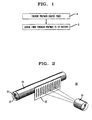
- FIG. 1 is a flow diagram depicting the steps involved in forming a grating in polymer coated fiber.
- FIG. 2 is a schematic view in partial cross section showing the arrangement used in grating formation.
- FIG. 1 is a flow diagram depicting the steps in forming a grating in polymer-coated fiber.
- the grating can be a Bragg grating or a long period grating.
- the first step is to provide an optical fiber waveguide having a polymer coating with low ultraviolet absorption polymer.
- the optical fiber as is well known, comprises an inner core of relatively high refractive index and an outer cladding.
- the inner core is made of UV photosensitive glass, such as germanosilicate, so that a grating can be written by UV radiation.
- the outer polymer coating should be of low UV absorbing polymer such as an aliphatic poly(meth)acrylate, a silsesquioxane, a vinyl ether, or an alkyl substituted silicone.
- the fiber is sensitized to UV radiation as by treating the fiber with deuterium D 2 .
- This preferably involves placing the fiber in a D 2 gas environment, advantageously at an elevated pressure and temperature, so that D 2 will diffuse through the polymer, the cladding and into core.
- Typical treatment conditions are 3500 psi, 50-70°C for 3 days. The treatment enhances the sensitivity of the UV photosensitive core so that the grating can be written at lower intensity.
- FIG. 2 which shows typical apparatus for practicing the method, includes a typical fiber 20 comprising a core 21, a cladding 22 surrounding the core, and an outer polymer coating 23.
- Block B shows that the next step is to expose the fiber by side writing through the polymer and cladding, a pattern of UV radiation corresponding to the desired grating. Successive radiation intensity peaks are spaced apart by the desired grating spacing.
- the grating pattern can be defined by a mask along the fiber such as an amplitude mask or a phase mask schematically illustrated in FIG. 2. UV light from laser 24 passes through mask 25, the polymer coating 23, and the cladding 22 to write a pattern of index changes along the photosensitive core 21. Alternatively, the pattern can be defined by two interfering beams of UV radiation. The UV radiation should be at a sufficiently low intensity that it does not seriously damage the polymer coating. Methods for forming gratings in polymer-coated fiber can be better understood by consideration of the following specific examples.
- a methylsilsesquioxane-coated fiber treated with D 2 was exposed to UV light from a KrF excimer laser.
- An amplitude mask was used to produce long period gratings.
- the fiber was held taut next to the amplitude mask, and its side adjacent to the mask was exposed to the UV radiation.
- 1 dB loss developed at the selected wavelength after exposure for approximately 5 minutes. Examination of the fiber surface showed some physical damage to the polymer with periodicity comparable to the amplitude mask, but the coating remained intact and the damage appeared superficial. Decreasing the power to 100 mJ/cm 2 resulted in 0.5 dB loss, and minor damage to the surface of the polymer.
- UV laser pulses at 242 nm were obtained from a frequency-doubled dye laser (which was pumped by a KrF excimer laser). The radiation was defocused to decrease the fluence.
- the focal point was moved 2 inches behind the fiber. After - 3 minutes of exposure at 20 mW there was no evidence of a grating impressed in the fiber core.
- the focal point was moved to within 1 inch of the fiber. A weak reflector ( ⁇ 3%) was observed.
- a 10% reflector was grown in less than 1.5 minutes and an - 70% reflector was grown after 6 minutes of exposure. In none of these cases was damage to the polymer coating detected.
Description
- This invention relates to methods for forming gratings, such as Bragg gratings, in optical fibers and, in particular, to a method for forming photo-induced gratings in polymer-coated optical fibers without removing the polymer.
- The dominant method for writing photo-induced gratings in optical fibers is side-writing with ultraviolet (UV) light through the fiber cladding. An optical fiber having a photosensitive glass core and a surrounding cladding is exposed to ultraviolet light having an intensity which varies periodically along a length of the fiber. The periodically varying intensity pattern is typically provided by applying a UV beam to an optical phase grating as described in Anderson et al United States Patent No. 5,327,515 issued July 5, 1994 which is incorporated herein by reference. Alternatively, the intensity pattern can be provided by an amplitude mask or by interfering a pair of coherent UV beams as described in W. H. Glenn et al United States Patent No. 4,725,110 issued February 16, 1988, incorporated herein by reference. In each of these conventional techniques, the source of UV light is typically a high intensity Excimer laser.
- Surprisingly, the rate-determining step in conventional fiber grating manufacture is not writing the grating but rather removing and subsequently reapplying the protective polymer coating that the fiber was provided at manufacture. These coatings are needed to protect the sensitive fiber from contamination and mechanical damage, but typical coatings significantly absorb UV radiation and interfere with grating formation. Moreover the coating would be damaged by UV laser beams. Thus, an initial step in conventional grating formation is stripping the polymer coating, as by soaking the fiber in hot sulfuric acid. A new coating must be applied and cured after the grating is formed. The coating removal and reapplication steps consume more than half the time required to write a grating in the conventional process.
- The present invention concerns a method of forming a grating in an optical fiber, as defined in claim 1.
- Recognizing the rate-determining nature of the coating removal and recoating steps, applicants have demonstrated that with proper combination of low absorbing polymer, glass and low intensity radiation, UV-induced gratings can be side-written into polymer coated fibers without removing the polymer, thus permitting high speed fabrication of fiber gratings.
- The advantages, nature and various additional features of the invention will appear more fully upon consideration of the illustrative embodiments now to be described in detail in connection with the accompanying drawings. In the drawings:
- FIG. 1 is a flow diagram depicting the steps involved in forming a grating in polymer coated fiber.
- FIG. 2 is a schematic view in partial cross section showing the arrangement used in grating formation.
- It is to be understood that these drawings are for purposes of illustrating the concepts of the invention and are not to scale.
- Referring to the drawings, FIG. 1 is a flow diagram depicting the steps in forming a grating in polymer-coated fiber. The grating can be a Bragg grating or a long period grating. As shown in block A of FIG. 1, the first step is to provide an optical fiber waveguide having a polymer coating with low ultraviolet absorption polymer. The optical fiber, as is well known, comprises an inner core of relatively high refractive index and an outer cladding. The inner core is made of UV photosensitive glass, such as germanosilicate, so that a grating can be written by UV radiation. The outer polymer coating should be of low UV absorbing polymer such as an aliphatic poly(meth)acrylate, a silsesquioxane, a vinyl ether, or an alkyl substituted silicone.
- Advantageously, the fiber is sensitized to UV radiation as by treating the fiber with deuterium D2. This preferably involves placing the fiber in a D2 gas environment, advantageously at an elevated pressure and temperature, so that D2 will diffuse through the polymer, the cladding and into core. Typical treatment conditions are 3500 psi, 50-70°C for 3 days. The treatment enhances the sensitivity of the UV photosensitive core so that the grating can be written at lower intensity.
- FIG. 2, which shows typical apparatus for practicing the method, includes a
typical fiber 20 comprising acore 21, acladding 22 surrounding the core, and anouter polymer coating 23. - Block B shows that the next step is to expose the fiber by side writing through the polymer and cladding, a pattern of UV radiation corresponding to the desired grating. Successive radiation intensity peaks are spaced apart by the desired grating spacing. The grating pattern can be defined by a mask along the fiber such as an amplitude mask or a phase mask schematically illustrated in FIG. 2. UV light from
laser 24 passes throughmask 25, thepolymer coating 23, and thecladding 22 to write a pattern of index changes along thephotosensitive core 21. Alternatively, the pattern can be defined by two interfering beams of UV radiation. The UV radiation should be at a sufficiently low intensity that it does not seriously damage the polymer coating.
Methods for forming gratings in polymer-coated fiber can be better understood by consideration of the following specific examples. - A methylsilsesquioxane-coated fiber treated with D2 was exposed to UV light from a KrF excimer laser. An amplitude mask was used to produce long period gratings. The fiber was held taut next to the amplitude mask, and its side adjacent to the mask was exposed to the UV radiation. At 130 mJ/cm2 1 dB loss developed at the selected wavelength after exposure for approximately 5 minutes. Examination of the fiber surface showed some physical damage to the polymer with periodicity comparable to the amplitude mask, but the coating remained intact and the damage appeared superficial. Decreasing the power to 100 mJ/cm2 resulted in 0.5 dB loss, and minor damage to the surface of the polymer.
- In this example, using a similar methylsilsesquioxane coated fiber, UV laser pulses at 242 nm were obtained from a frequency-doubled dye laser (which was pumped by a KrF excimer laser). The radiation was defocused to decrease the fluence. In the first attempt, the focal point was moved 2 inches behind the fiber. After - 3 minutes of exposure at 20 mW there was no evidence of a grating impressed in the fiber core. In the second attempt, the focal point was moved to within 1 inch of the fiber. A weak reflector (∼ 3%) was observed. In subsequent attempts a 10% reflector was grown in less than 1.5 minutes and an - 70% reflector was grown after 6 minutes of exposure. In none of these cases was damage to the polymer coating detected.
Claims (4)
- A method for forming a grating in an optical fiber comprising the steps of:providing a polymer-coated optical fiber, said fiber having a cladding and a photosensitive core and the polymer which coats the fiber being made of a low ultraviolet absorbing material; andwithout removing said polymer, exposing said core by side writing through said polymer and cladding, to a pattern of ultraviolet radiation corresponding to the grating to be formed.
- The method of claim 1 wherein said polymer-coated fiber is coated with a polymer selected from the group consisting of aliphatic poly(meth)acrylates, silsesquioxanes, alkyl-substituted silicones and vinyl ethers.
- The method of claim 1 wherein said polymer coated fiber is coated with methylsilsesquioxane.
- The method of claim 1 further comprising the step of loading D2 into the core of said fiber prior to exposing said core.
Applications Claiming Priority (2)
| Application Number | Priority Date | Filing Date | Title |
|---|---|---|---|
| US08/515,625 US5620495A (en) | 1995-08-16 | 1995-08-16 | Formation of gratings in polymer-coated optical fibers |
| US515625 | 1995-08-16 |
Publications (2)
| Publication Number | Publication Date |
|---|---|
| EP0762158A1 EP0762158A1 (en) | 1997-03-12 |
| EP0762158B1 true EP0762158B1 (en) | 2003-07-23 |
Family
ID=24052112
Family Applications (1)
| Application Number | Title | Priority Date | Filing Date |
|---|---|---|---|
| EP96305793A Expired - Lifetime EP0762158B1 (en) | 1995-08-16 | 1996-08-07 | Formation of gratings in polymer-coated optical fibers |
Country Status (4)
| Country | Link |
|---|---|
| US (1) | US5620495A (en) |
| EP (1) | EP0762158B1 (en) |
| JP (1) | JP3335086B2 (en) |
| DE (1) | DE69629153T2 (en) |
Families Citing this family (60)
| Publication number | Priority date | Publication date | Assignee | Title |
|---|---|---|---|---|
| US5903690A (en) * | 1996-07-05 | 1999-05-11 | D-Star Technologies, Inc. | Method for changing the refraction index in germanium silicate glass |
| JP3929495B2 (en) * | 1996-01-18 | 2007-06-13 | ブリティッシュ・テレコミュニケーションズ・パブリック・リミテッド・カンパニー | Optical waveguide with photosensitive refractive index cladding |
| US6272886B1 (en) * | 1996-10-23 | 2001-08-14 | 3M Innovative Properties Company | Incremental method of producing multiple UV-induced gratings on a single optical fiber |
| US5773486A (en) * | 1996-09-26 | 1998-06-30 | Lucent Technologies Inc. | Method for the manufacture of optical gratings |
| US5745615A (en) * | 1996-10-11 | 1998-04-28 | Lucent Technologies Inc. | Method of making an optical fiber grating, and article made by the method |
| US6311524B1 (en) * | 2000-07-14 | 2001-11-06 | 3M Innovative Properties Company | Accelerated method for increasing the photosensitivity of a glassy material |
| US5718738A (en) * | 1996-11-04 | 1998-02-17 | Lucent Technologies Inc. | Method for making continuously chirped fiber bragg gratings |
| US5745617A (en) * | 1996-12-30 | 1998-04-28 | D-Star Technologies, Llc | Near-ultra-violet formation of refractive-index grating using reflective phase mask |
| WO1998029770A1 (en) * | 1996-12-30 | 1998-07-09 | D-Star Technologies, Inc. | Near-ultraviolet formation of refractive-index grating using phase mask |
| IT1292316B1 (en) * | 1997-05-20 | 1999-01-29 | Cselt Centro Studi Lab Telecom | PROCEDURE AND DEVICE FOR THE CREATION OF FIBER BRAGG GRATINGS OR OPTICAL WAVE GUIDES. |
| US5953471A (en) * | 1997-07-01 | 1999-09-14 | Lucent Technologies, Inc. | Optical communication system having short period reflective Bragg gratings |
| US6174648B1 (en) * | 1997-07-08 | 2001-01-16 | Oki Electric Industry Co., Ltd. | Optical filter fabrication method using fiber holder with spiral groove and phase mask with spiral diffraction grating |
| KR100258968B1 (en) * | 1997-07-21 | 2000-06-15 | 윤종용 | Amplitude mask and apparatus for manufacturing long period grating filter using the same |
| KR100277353B1 (en) * | 1997-08-26 | 2001-01-15 | 윤종용 | Fabication method for long period grating filter |
| US6054253A (en) * | 1997-10-10 | 2000-04-25 | Mcgill University-The Royal Institute For The Advancement Of Learning | Solvent-assisted lithographic process using photosensitive sol-gel derived glass for depositing ridge waveguides on silicon |
| EP1035425A4 (en) * | 1997-11-26 | 2005-12-28 | Mitsubishi Cable Ind Ltd | Fiber grating, its manufacturing method and its manufacturing device |
| KR100265794B1 (en) * | 1997-12-08 | 2000-09-15 | 윤종용 | Amplitude mask of its periodicity variable and device for fabricating long-period grating filter thereof |
| US6130973A (en) * | 1998-03-26 | 2000-10-10 | Institut National D'optique | Method and apparatus for spectrally designing all-fiber filters |
| AUPP390098A0 (en) * | 1998-06-04 | 1998-07-02 | University Of Sydney, The | An absorbing layer for minimising substrate exposure during the uv writing of a waveguide grating in addition to birefringent control system |
| JP3869121B2 (en) | 1998-06-26 | 2007-01-17 | 古河電気工業株式会社 | Method for forming fiber grating |
| US6522797B1 (en) | 1998-09-01 | 2003-02-18 | Input/Output, Inc. | Seismic optical acoustic recursive sensor system |
| US6204304B1 (en) * | 1998-09-28 | 2001-03-20 | Lucent Technologies Inc. | Vinyl ether-based optical fiber coatings |
| US5989627A (en) * | 1998-09-28 | 1999-11-23 | Lucent Technologies Inc. | Vinyl ether terminated oligomers and polymers |
| JP2000180640A (en) * | 1998-12-16 | 2000-06-30 | Mitsubishi Cable Ind Ltd | Gain equalizer, light amplifier and optical fiber communication system |
| US6528239B1 (en) * | 1999-01-15 | 2003-03-04 | Sabeus Photonics, Inc. | Method of forming a grating in a waveguide |
| US6222973B1 (en) | 1999-01-15 | 2001-04-24 | D-Star Technologies, Inc. | Fabrication of refractive index patterns in optical fibers having protective optical coatings |
| CA2259350A1 (en) * | 1999-01-20 | 2000-07-20 | Hamid Hatami-Hanza | Method for volume production of optical grating devices with tuning capability |
| CN1092338C (en) * | 1999-03-12 | 2002-10-09 | 清华大学 | Method for making optical fibre raster with Moire streak amplitude template |
| KR100334799B1 (en) | 1999-07-07 | 2002-05-02 | 윤종용 | Apparatus and method for fabricating fiber grating |
| US20010035029A1 (en) * | 1999-07-12 | 2001-11-01 | Akira Ikushima | Method of manufacturing an optical fiber |
| KR100303284B1 (en) * | 1999-07-28 | 2001-11-01 | 윤종용 | Apparatus for manufacturing long period optical fiber gratings having less dependence on polarization and long period optical fiber gratings manufactured by the same |
| US6442305B1 (en) * | 1999-12-21 | 2002-08-27 | Sabeus Photonics, Inc. | Method for altering the refractive index of optical fibers using stress |
| US6795636B1 (en) | 2000-03-05 | 2004-09-21 | 3M Innovative Properties Company | Radiation-transmissive films on glass articles |
| US6696157B1 (en) | 2000-03-05 | 2004-02-24 | 3M Innovative Properties Company | Diamond-like glass thin films |
| US7039289B1 (en) | 2000-05-19 | 2006-05-02 | Optinetrics, Inc. | Integrated optic devices and processes for the fabrication of integrated optic devices |
| US6881530B1 (en) * | 2000-05-19 | 2005-04-19 | Optinetrics, Inc. | Thin film sol-gel derived glass |
| US7016589B2 (en) * | 2000-05-19 | 2006-03-21 | Optinetrics, Inc. | Thermally-assisted photo-lithographic process using sol-gel derived glass and products made thereby |
| EP1158088A3 (en) * | 2000-05-26 | 2003-01-22 | Voith Paper Patent GmbH | Process and device for treating a fibrous suspension |
| US7022382B1 (en) | 2000-06-16 | 2006-04-04 | Alcatel | UV-cure of coatings for an optical fiber with a laser |
| US6708741B1 (en) | 2000-08-24 | 2004-03-23 | Ocean Spray Cranberries, Inc. | Beverage dispenser |
| KR100342473B1 (en) * | 2000-08-29 | 2002-06-28 | 윤종용 | Optical fiber ribbon cable |
| FR2813810A1 (en) * | 2000-09-13 | 2002-03-15 | Sebastien Fourneron | Method of appositioning motif on glass part uses longitudinal mask with window in shape of motif, placing part against mask surface and treating zone when zone is opposite window during advancement of part |
| US6652975B2 (en) | 2001-03-02 | 2003-11-25 | Lucent Technologies Inc. | Adherent silicones |
| US6532327B1 (en) * | 2001-03-13 | 2003-03-11 | 3M Innovative Properties Company | Refractive index grating manufacturing process |
| US6853785B2 (en) * | 2001-12-14 | 2005-02-08 | 3M Innovative Properties Co. | Index modulation in glass using a femtosecond laser |
| US20030199603A1 (en) | 2002-04-04 | 2003-10-23 | 3M Innovative Properties Company | Cured compositions transparent to ultraviolet radiation |
| JP3923386B2 (en) * | 2002-04-05 | 2007-05-30 | 古河電気工業株式会社 | Glass optical fiber for fiber grating |
| EP1500960A4 (en) * | 2002-04-26 | 2005-10-26 | Japan Science & Tech Agency | Fiber grating and method for making the same |
| US6856745B2 (en) * | 2002-07-02 | 2005-02-15 | Lucent Technologies Inc. | Waveguide and applications therefor |
| US6822190B2 (en) * | 2002-12-12 | 2004-11-23 | 3M Innovative Properties Company | Optical fiber or waveguide lens |
| US7297731B2 (en) * | 2003-03-11 | 2007-11-20 | 3M Innovative Properties Company | Coating dispersions for optical fibers |
| US7327907B2 (en) | 2004-10-14 | 2008-02-05 | Northrop Grumman Corporation | Optical sensor fiber with protective jacketing layers |
| CN1321927C (en) * | 2005-03-08 | 2007-06-20 | 薛秉荣 | Prepn process of soaking treatment agent for modification of glass fiber yarn |
| US10038427B2 (en) | 2012-10-17 | 2018-07-31 | Qualcomm Incorporated | Power path switching in an electronic device including a plurality of charging ports |
| US9353001B2 (en) * | 2013-03-14 | 2016-05-31 | Ofs Fitel, Llc | Fiber bragg gratings in carbon-coated optical fibers and techniques for making same |
| JP6104835B2 (en) * | 2013-03-14 | 2017-03-29 | オーエフエス ファイテル,エルエルシー | Fiber Bragg gratings in carbon-coated optical fibers and techniques for their manufacture. |
| CA2981343C (en) | 2014-04-03 | 2021-12-07 | Universite Laval | Writing of high mechanical strength fiber bragg gratings using ultrafast pulses and a phase mask |
| JP6442041B2 (en) | 2014-07-29 | 2018-12-19 | オーエフエス ファイテル,エルエルシー | UV-curable silsesquioxane-containing light-through optical fiber coating for the production of optical fiber Bragg gratings and fibers made therefrom |
| US9634462B2 (en) * | 2014-10-15 | 2017-04-25 | Nlight, Inc. | Slanted FBG for SRS suppression |
| US10788621B2 (en) * | 2015-07-07 | 2020-09-29 | Ofs Fitel, Llc | UV-transparent optical fiber coating for high temperature application, and fibers made therefrom |
Family Cites Families (12)
| Publication number | Priority date | Publication date | Assignee | Title |
|---|---|---|---|---|
| BE789176A (en) * | 1971-09-24 | 1973-01-15 | Siemens Ag | DEVICE FOR THE INTRODUCTION AND EXTRACTION OF LIGHT IN DIELECTRIC OPTICAL WAVE GUIDES AND PROCESS FOR ITS MANUFACTURING |
| US3993485A (en) * | 1975-05-27 | 1976-11-23 | Bell Telephone Laboratories, Incorporated | Photopolymerization process and related devices |
| US4486213A (en) * | 1982-09-29 | 1984-12-04 | Corning Glass Works | Drawing laminated polarizing glasses |
| JP2521708B2 (en) * | 1984-08-13 | 1996-08-07 | ユナイテッド テクノロジーズ コーポレーション | Method of forming a grating in an optical fiber |
| US4749248A (en) * | 1985-11-06 | 1988-06-07 | American Telephone And Telegraph Company At&T Bell Laboratories | Device for tapping radiation from, or injecting radiation into, single made optical fiber, and communication system comprising same |
| US5164218A (en) * | 1989-05-12 | 1992-11-17 | Nippon Soken, Inc. | Semiconductor device and a method for producing the same |
| US5478371A (en) * | 1992-05-05 | 1995-12-26 | At&T Corp. | Method for producing photoinduced bragg gratings by irradiating a hydrogenated glass body in a heated state |
| US5287427A (en) * | 1992-05-05 | 1994-02-15 | At&T Bell Laboratories | Method of making an article comprising an optical component, and article comprising the component |
| US5235659A (en) * | 1992-05-05 | 1993-08-10 | At&T Bell Laboratories | Method of making an article comprising an optical waveguide |
| US5500031A (en) * | 1992-05-05 | 1996-03-19 | At&T Corp. | Method for increasing the index of refraction of a glassy material |
| US5327515A (en) * | 1993-01-14 | 1994-07-05 | At&T Laboratories | Method for forming a Bragg grating in an optical medium |
| US5559907A (en) * | 1994-02-17 | 1996-09-24 | Lucent Technologies Inc. | Method of controlling polarization properties of a photo-induced device in an optical waveguide and method of investigating structure of an optical waveguide |
-
1995
- 1995-08-16 US US08/515,625 patent/US5620495A/en not_active Expired - Lifetime
-
1996
- 1996-08-07 DE DE69629153T patent/DE69629153T2/en not_active Expired - Lifetime
- 1996-08-07 EP EP96305793A patent/EP0762158B1/en not_active Expired - Lifetime
- 1996-08-14 JP JP21396596A patent/JP3335086B2/en not_active Expired - Fee Related
Also Published As
| Publication number | Publication date |
|---|---|
| JPH09113741A (en) | 1997-05-02 |
| DE69629153D1 (en) | 2003-08-28 |
| DE69629153T2 (en) | 2004-05-27 |
| JP3335086B2 (en) | 2002-10-15 |
| EP0762158A1 (en) | 1997-03-12 |
| US5620495A (en) | 1997-04-15 |
Similar Documents
| Publication | Publication Date | Title |
|---|---|---|
| EP0762158B1 (en) | Formation of gratings in polymer-coated optical fibers | |
| US5930420A (en) | Method for producing photo induced grating devices by UV irradiation of heat-activated hydrogenated glass | |
| JP3727358B2 (en) | Article including optical element and method of manufacturing the same | |
| US5235659A (en) | Method of making an article comprising an optical waveguide | |
| US6310998B1 (en) | Fabrication of refractive index patterns in optical fibers having protective optical coatings | |
| US5495548A (en) | Photosensitization of optical fiber and silica waveguides | |
| US5478371A (en) | Method for producing photoinduced bragg gratings by irradiating a hydrogenated glass body in a heated state | |
| CN100551860C (en) | Coating dispersions for optical fibers | |
| JP3153083B2 (en) | Optical element stabilization method | |
| Poumellec et al. | The photorefractive Bragg gratings in the fibers for telecommunications | |
| KR20010102214A (en) | Methods of photosensitizing glasses with hydrogen or deuterium and waveguides resulting therefrom | |
| AU3901897A (en) | Variable period amplitude grating mask and method for use | |
| KR980003650A (en) | Optical fiber type diffraction grating and its manufacturing method | |
| Chen et al. | Rapid long-period grating formation in hydrogen-loaded fibre with 157nm F^ sub 2^-laser radiation | |
| US6653051B2 (en) | Photoinduced grating in oxynitride glass | |
| US6396983B1 (en) | Formation of gratings in optical fibers coated with UV-curable polymer | |
| US20030152352A1 (en) | Method of forming a grating in a waveguide | |
| US7515792B2 (en) | Method of increasing photosensitivity of glasses to ultrafast infrared laser radiation using hydrogen or deuterium | |
| Dragomir et al. | Long-period fibre grating formation with 264 nm femtosecond radiation | |
| US6456771B1 (en) | Optical fiber with a pure silica core having a bragg grating formed in its core and a process for providing same | |
| US6549706B2 (en) | Photoinduced grating in oxynitride glass | |
| Salik et al. | Thermally stable gratings in optical fibers without temperature annealing | |
| CA2115906C (en) | Photosensitization of optical fiber and silica waveguides | |
| Riziotis et al. | Rapid heat treatment for photosensitivity locking in deuterium-loaded planar optical waveguides | |
| Starodubov et al. | Fiber Bragg gratings with reflectivity> 97% fabricated through polymer jacket using near-UV light |
Legal Events
| Date | Code | Title | Description |
|---|---|---|---|
| PUAI | Public reference made under article 153(3) epc to a published international application that has entered the european phase |
Free format text: ORIGINAL CODE: 0009012 |
|
| AK | Designated contracting states |
Kind code of ref document: A1 Designated state(s): DE FR GB |
|
| 17P | Request for examination filed |
Effective date: 19970829 |
|
| GRAH | Despatch of communication of intention to grant a patent |
Free format text: ORIGINAL CODE: EPIDOS IGRA |
|
| GRAH | Despatch of communication of intention to grant a patent |
Free format text: ORIGINAL CODE: EPIDOS IGRA |
|
| GRAA | (expected) grant |
Free format text: ORIGINAL CODE: 0009210 |
|
| AK | Designated contracting states |
Designated state(s): DE FR GB |
|
| REG | Reference to a national code |
Ref country code: GB Ref legal event code: FG4D |
|
| REF | Corresponds to: |
Ref document number: 69629153 Country of ref document: DE Date of ref document: 20030828 Kind code of ref document: P |
|
| ET | Fr: translation filed | ||
| PLBE | No opposition filed within time limit |
Free format text: ORIGINAL CODE: 0009261 |
|
| STAA | Information on the status of an ep patent application or granted ep patent |
Free format text: STATUS: NO OPPOSITION FILED WITHIN TIME LIMIT |
|
| 26N | No opposition filed |
Effective date: 20040426 |
|
| PGFP | Annual fee paid to national office [announced via postgrant information from national office to epo] |
Ref country code: DE Payment date: 20140827 Year of fee payment: 19 |
|
| PGFP | Annual fee paid to national office [announced via postgrant information from national office to epo] |
Ref country code: GB Payment date: 20140827 Year of fee payment: 19 Ref country code: FR Payment date: 20140818 Year of fee payment: 19 |
|
| REG | Reference to a national code |
Ref country code: DE Ref legal event code: R119 Ref document number: 69629153 Country of ref document: DE |
|
| GBPC | Gb: european patent ceased through non-payment of renewal fee |
Effective date: 20150807 |
|
| REG | Reference to a national code |
Ref country code: FR Ref legal event code: ST Effective date: 20160429 |
|
| PG25 | Lapsed in a contracting state [announced via postgrant information from national office to epo] |
Ref country code: GB Free format text: LAPSE BECAUSE OF NON-PAYMENT OF DUE FEES Effective date: 20150807 Ref country code: DE Free format text: LAPSE BECAUSE OF NON-PAYMENT OF DUE FEES Effective date: 20160301 |
|
| PG25 | Lapsed in a contracting state [announced via postgrant information from national office to epo] |
Ref country code: FR Free format text: LAPSE BECAUSE OF NON-PAYMENT OF DUE FEES Effective date: 20150831 |