EP0762361B1 - Navigation system for vehicles - Google Patents
Navigation system for vehicles Download PDFInfo
- Publication number
- EP0762361B1 EP0762361B1 EP96113536A EP96113536A EP0762361B1 EP 0762361 B1 EP0762361 B1 EP 0762361B1 EP 96113536 A EP96113536 A EP 96113536A EP 96113536 A EP96113536 A EP 96113536A EP 0762361 B1 EP0762361 B1 EP 0762361B1
- Authority
- EP
- European Patent Office
- Prior art keywords
- advancing direction
- guide branch
- information
- branch point
- route
- Prior art date
- Legal status (The legal status is an assumption and is not a legal conclusion. Google has not performed a legal analysis and makes no representation as to the accuracy of the status listed.)
- Expired - Lifetime
Links
Images


Classifications
-
- G—PHYSICS
- G01—MEASURING; TESTING
- G01C—MEASURING DISTANCES, LEVELS OR BEARINGS; SURVEYING; NAVIGATION; GYROSCOPIC INSTRUMENTS; PHOTOGRAMMETRY OR VIDEOGRAMMETRY
- G01C21/00—Navigation; Navigational instruments not provided for in groups G01C1/00 - G01C19/00
- G01C21/26—Navigation; Navigational instruments not provided for in groups G01C1/00 - G01C19/00 specially adapted for navigation in a road network
- G01C21/34—Route searching; Route guidance
- G01C21/36—Input/output arrangements for on-board computers
- G01C21/3626—Details of the output of route guidance instructions
- G01C21/3635—Guidance using 3D or perspective road maps
-
- G—PHYSICS
- G08—SIGNALLING
- G08G—TRAFFIC CONTROL SYSTEMS
- G08G1/00—Traffic control systems for road vehicles
- G08G1/09—Arrangements for giving variable traffic instructions
- G08G1/0962—Arrangements for giving variable traffic instructions having an indicator mounted inside the vehicle, e.g. giving voice messages
- G08G1/0968—Systems involving transmission of navigation instructions to the vehicle
- G08G1/0969—Systems involving transmission of navigation instructions to the vehicle having a display in the form of a map
Definitions
- the present invention relates to a technical field of a navigation system for vehicles for providing a driver of a vehicle with information on a route to a destination when the vehicle is driven along a route unfamiliar to the driver.
- a vehicular navigation system is a system, which searches an optimal route from the present position of the vehicle or from a specified starting point to a destination based on inputted data such as the destination data, and provides the driver with information on a route to reach the destination when the vehicle is driven along a road unfamiliar to the driver by displaying a road map on a screen of a display unit based on the suggested optimal route and by displaying the suggested route or the present position of the vehicle on the map.
- a route is searched from the present position of the vehicle or from a destination based on inputted data such as a destination, a transit point, etc., and a suggested route is displayed on a map or an advancing direction is displayed by an arrow on an enlarged map.
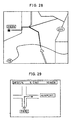
- Fig. 28 represents a map, which shows a route to guide the vehicle to a destination (park marked with an asterisk) via a highway shown by a white line (outlined line).
- Fig. 29 is an enlarged view of an area near a branch point for guiding toward a route from PARI to an airport, and an arrow indicating the advancing direction from the branch point and a message "5.0 miles; 10 minutes to the destination" is displayed.
- the suggested route is drawn on a map as shown in Fig. 28, and the driver must find out the turning point and the turning direction by watching the map. Thus, it takes some time until the driver fully understands the situation. Also, in case the present position of the vehicle, the advancing direction, or the route already driven are displayed by the same magnification factor, it is difficult for the driver to discriminate the information necessary for immediate guiding from other information. Because a large number of information are displayed in addition to the information on the present position and it is not always easy to recognize the information on the present position, this is not always satisfactory in terms of recognizability. For example, in case a road is curved, it is sometimes difficult to judge whether the road is curved or not.
- A. Spoerri novel route guides and displays
- proceedings of the vehicle navigation and information systems conference, Ottawa, October 12-15, 1993 describes a vehicular navigation system wherein a navigation map of the current street and the next street to be traveled is displayed in respective on the screen.
- the travel direction of the street is displayed in due order using a directional arrow and a guidance to be performed next is displayed in the largest representation in size.
- a vehicular navigation system comprises a present position detecting means for detecting the present position of the vehicle, an input means for inputting information necessary for calculating an optimal route, a display means for displaying information for route guidance, an information memory means for storing all necessary data for route guidance including guidance road data, a route searching means for searching an optimal route based on the information inputted by said input means, a route information memory means for storing information of a route searched and suggested by said route searching means, and a guidance control means for reading two directions, i.e.
- Fig. 1 is a general block diagram of an embodiment of a vehicular navigation system according to the present invention.
- the vehicular navigation system according to the present invention comprises an input/output unit 1 for inputting and outputting information relating to route guidance, a present position detecting unit (present position detecting means) 2 for detecting information relating to the present position of the vehicle, an information memory unit (information memory means) 3 for storing data of navigation necessary for calculating an optimal route guidance display and sound data required for route guidance and for storing programs (OS and/or application), and a central processing unit 4 for performing display/sound guidance processing necessary for route search processing and route guidance and for controlling the entire system.
- an input/output unit 1 for inputting and outputting information relating to route guidance
- a present position detecting unit (present position detecting means) 2 for detecting information relating to the present position of the vehicle
- an information memory unit (information memory means) 3 for storing data of navigation necessary for calculating an optimal route guidance display and sound data required for route guidance and for storing programs (OS and
- the input/output unit 1 is provided with function to input a destination, to specify navigation processing to the central processing unit 4 at the request of the driver so that guidance information is given at least by either sound or screen when the driver needs such information and also to print data after the processing.
- the input unit comprises a touch switch 11 and an operation switch (input-means) for inputting the destination using telephone number or coordinates on a map or for requesting route guidance.
- it may be an input unit such as a remote controller.
- the output unit comprises a display unit (output display means) 12 for displaying the inputted data on screen or for automatically displaying route guidance on screen upon the request of the driver, a printer 13 for printing data processed by the central processing unit 4 or data stored in the information storage unit 3, and a speaker for outputting route guidance by means of voice.
- a display unit output display means 12 for displaying the inputted data on screen or for automatically displaying route guidance on screen upon the request of the driver
- a printer 13 for printing data processed by the central processing unit 4 or data stored in the information storage unit 3
- a speaker for outputting route guidance by means of voice.
- a voice recognizing unit for inputting voice or a card reader for reading data recorded on IC card or magnetic card may be added.
- a data communication unit may be added, by which it is possible to send or receive data to or from an information source such as a personal computer where the data specific to the driver such as map data, destination data, etc. are stored.
- the display unit 12 comprises a color CRT and a color liquid crystal display, and all screens necessary for navigation such as route setting screen based on map data and guidance data processed by the central processing unit 4, a sector view screen, intersection view screen, etc. are outputted in color display. Further, buttons for setting route guidance, for guidance during route guidance and switching the screens are displayed. In particular, information on transit intersection such as name of transit intersection is outputted in pop art color display on the sector view screen.
- the display unit 12 is installed on an instrument panel near the driver's seat, and the driver can confirm the present position of the vehicle by watching the map displayed and can obtain information on the route ahead.
- the display unit 12 is provided with a touch switch 11 corresponding to display of functional buttons. By touching the buttons, the above operation can be executed based on the inputted signal.
- An input signal generating means comprising these buttons and the touch switch constitutes the input unit, but detailed description is not given here.
- the present position detecting unit 2 is to detect or receive information relating to the present position of the vehicle, and it comprises an absolute heading sensor 24 having geomagnetic sensor and the like, a relative heading sensor 25 having steering sensor, gyro, etc., a distance sensor 26 for detecting traveled distance from number of revolutions of wheels, a GPS receiver 21 utilizing the global positioning system (GPS), and a communication unit 5.
- the communication unit 5 comprises a VICS receiver 22 serving as traffic information acquiring means and a data transceiver 23.
- VICS Vehicle Information & Communication System
- VICS Vehicle Information & Communication System
- FM multiplex transmits crude information to wider area, while the information transmitted by radio beacon and optical beacon is detailed information for narrow area within about 10 km in radius around the beacon, and the information is received when the vehicle passes by the beacon.
- VICS transmission data contains degree of traffic congestion (e.g. closed to traffic, congestion, traffic jam, heavy traffic, normal traffic, etc.), the foremost position of congestion, length of congestion, traffic restriction (information on construction, no thoroughfare, etc.), traveling time (time required at a predetermined speed).
- the data transceiver is, for example, a portable telephone or a personal computer, by which information necessary for navigation is sent to or received from a traffic information center (such as ATIS) at the request of the driver.
- a traffic information center such as ATIS
- the information storage unit 3 is an external storage unit, which stores navigation program and data in an external storage medium such as CD-ROM (hereinafter simply referred as "CD"), optical CD, IC card, etc.
- the program comprises a map drawing unit, a route searching unit, a route guidance unit, a present position calculating unit, a destination setting operation control unit, etc. and contains an application unit for signal processing of navigation and an OS unit.
- programs for processing such as route searching, programs and data necessary for programs to execute display output control for route guidance and for audio output control for audio guidance, and further, display information data necessary for route guidance and map display are stored.
- the data stored include map data, intersection data, road data, various guidance data, and all necessary data for navigation.
- a program for setting a destination and a transit point based on positional information from the present position detecting unit 2 and on input signal from the input unit 11 and for executing route searching using the suggested road data
- a program route information converting means for converting the suggested road data based on traffic information acquired from the communication unit 5 and for executing route searching again
- a program for converting the suggested route to draw it 3-dimensionally a program for determining map drawing, map matching, audio output timing along the route and contents of voice phrase.
- the central processing unit 4 is provided with a CPU 40 for executing various computation processings and flash memory 41 for reading and storing programs from CD of the information storage unit 3. Even when programs on CD are changed, the flash memory 41 erases the existing programs and make them reloadable. Further, there are provided a 1st ROM 43a for storing programs to check programs of the flash memory 41 and for carrying out updating of the flash memory (program reading means), a RAM 42 for temporarily storing guidance information for the suggested route such as coordinates of the preset destination, road code number, etc. or the data under computation, and a 2nd ROM 43b for storing display information data necessary for route guidance and map display.
- the program for updating as described above may be stored in the external storage unit.
- an image memory 44 where image data used for screen display to the display unit is stored, an image processor for picking up image data from the image memory based on display control signal from CPU 40 and for outputting it to the display unit 12 after image processing, an audio processor 46 for synthesizing voice, phrase, a sizable sentence, sound, etc. as read from RAM 42 based on audio output control signal from CPU 40 and sending it to the speaker 16 after converting to analog signal, a communication interface 47 to send or receive input/output data by communication, a sensor input interface 48 for picking up sensor signal of the present position detecting unit 2, and a clock 49 for entering date and time to internal dialog information.
- CPU 40 calculates coordinates of the present position at a given time interval and writes them temporarily in RAM 42.
- the present position coordinates are subjected to map matching by taking detection error of various data into consideration. Output values by various types of sensors are corrected and compensated at all times.
- the route guidance is carried out by screen display and voice output, and the driver can select whether voice output should by used or not.
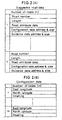
- Fig. 2 shows a part of the suggested (searched) road data file stored in the information storage unit 3, i.e. the data necessary for calculating the route by the route searching unit and for carrying out the route guidance.
- the data include road number, length, road attribute data, and address and size of configuration data, and address and size of guidance data.
- the road number is an identification number for each of the roads included in the map classified to outward course and return course for the roads between branch points such as intersections.
- the road attribute data are the data showing types of the road such as overpass, underpass, expressway, national road, general road, toll road, etc.
- the configuration data are the data showing configuration or shape of the road. As shown in Fig.
- the guidance data include name of intersection (or branch point), presence or absence of traffic signal, data of landmark (such as traffic signpost, signboards of filling station, convenience store, etc.), precaution point data (such as railroad crossing, tunnel), road name data and destination data.
- Fig. 3 is a flow chart for explaining flow of the entire vehicular navigation system according to the present invention.
- Initializing is carried out in Step S1.
- CPU 40 reads navigation program from CD-ROM and stores it in the flash memory 41.
- the present position is detected by the present position detecting unit 2, and a map of the neighborhood is displayed around the present position, and name and other data of the present position are displayed (Step S2).
- the destination is set using telephone number, address, name of facility, registered point, etc. (Step S3), and a route from the present position to the destination is searched (Step S4).
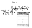
- the route to reach the destination is set as guidance road number data containing guidance road numbers as shown in Fig. 4.
- the present position detected by the present position detecting unit 2 is traced, and the route up to the destination is guided and displayed (Step S5).
- the present invention relates to a vehicular navigation system, in which marks such as arrows for indicating advancing direction at guide branch point or guide intersection (hereinafter referred as "guide branch point”) on a leading route.
- a guidance control means for changing display position of the advancing direction at a second guide branch point to match the advancing direction at a first guide branch point and for displaying the advancing direction at the second guide branch point at the same time.
- the guidance control means is provided with function to display the advancing direction at each guide branch point when the two guide branch points are adjacent to each other at a distance shorter than the predetermined distance and also with function to highlight or emphasize guidance information of advancing direction of the first guide branch point.
- the guidance control means is also provided with function to display the advancing direction guidance information at the first guide branch point at upper center of the display screen and to display the advancing direction guidance information at the second and subsequent guide branch points at upper right or left of the display screen or to overlap the guide branch points one after another with the nearer point on the upper layer.
- display position of the advancing direction at the second guide branch point is changed according to the advancing direction at the first guide branch point.
- the driver recognizes the advancing direction guidance at the next guide branch point
- the driver can recognize the advancing direction guidance information of the guide branch point after the next.
- advancing direction at each guide branch point is displayed when the distance between the guide branch points is short, it is easily recognized that the guide branch points are adjacent to each other. For example, when the vehicle must be turned left immediately after turning to right, the driver can drive the vehicle at ease.
- the driver can easily recognize the next advancing direction guidance.
- the advancing direction guidance information at the first guide branch point is displayed at upper center of the display screen, and the advancing direction guidance information at the second and subsequent guide branch points is displayed at upper right or left of the display screen with the nearer guide branch point on the upper layer.
- the uppermost advancing direction guidance information i.e. on top of the others
- the driver can recognize the number of turning points where the vehicle is to be turned has decreased because the remaining layers of the advancing direction guidances displayed on the screen have decreased.
- Fig. 14 to Fig. 16 show examples of major data files stored in the information storage unit 3 of Fig. 1 according to the present embodiment.
- Fig. 14 (A) represents guidance road data file, in which route has been searched by the route searching means and the data necessary for route guidance is stored.
- n For each of the number of roads (n), it consists of various data such as road number, length, road attribute data, address and size of configuration data, and address and size of guidance data.
- the road number is set for each direction (outward course and return course) and for each road between branch points.
- the road attribute data serving as road guidance auxiliary information data include the data indicating that the road is overpass, road alongside overpass, underpass, or road alongside underpass, and information on number of lanes a shown in Fig. 15 (A).
- the configuration data contain coordinate data including east longitude and north latitude to each of several meters of the node when each road is divided into a plurality of nodes as shown in Fig. 14 (B).
- the guidance data include the data such as name of intersection (or branch point, precaution point data, road -name data, address and size of road name voice data, and address and size of destination data.
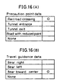
- the precaution data are the data indicating railroad crossing, tunnel entrance, tunnel exit, road width narrowing point etc., warning the driver at railroad crossing, tunnel, etc. other than the branch point as shown in Fig. 16 (A).
- the road name data indicate information of the type of road such as expressway, municipal expressway, toll road, general road (national road, prefectural road, other road), and indicating information such as main line or approach road for expressway, municipal expressway and toll road as shown in Fig. 15 (B).
- the data comprise the road type data and in-type number, i.e. individual number data for each road type.
- the destination data are the data such as destination road number, destination name, address and size of destination name voice data, destination direction data, and driving guidance data as shown in Fig. 14 (D).
- the destination direction data indicate information such as "invalid” (destination direction is not used), "unnecessary” (no guidance is necessary), "go straight ahead”, right ward direction, diagonally rightward direction, direction to return to right, leftward direction, diagonally leftward direction, and direction to return to left.
- the driving guidance data include the data for guiding as to which lane the vehicle should be driven along when there are a plurality of lanes as shown in Fig. 16 (B), indicating information such as bear right, bear left, bear toward the center or no suggestion.
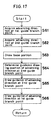
- Fig. 17 is a flow chart of the processing to draw a sector view for advancing direction guidance
- Fig. 18 shows advancing direction guidance screens.
- the present embodiment is characterized in that, based on the advancing direction at the first guide branch point, the position to draw or visualize the advancing direction guidance information at the second guide branch point is changed.
- drawing position of the second guide branch point is determined at right or at upper right ahead of the advancing direction.
- drawing position of the second guide branch point is determined at upper position ahead of the arrow of the advancing direction.
- drawing position of the second guide branch point is determined at upper left ahead of the advancing direction.
- the drawing position of the second guide branch point is determined based on the advancing direction at the first guide branch point, and, when the driver recognizes the next guidance, it is possible to recognize the guidance information after the next.
- the first advancing direction mark is partially overlapped and displayed on the second advancing direction mark. Because the first advancing direction guidance is displayed with highlight or emphasis, priority of the advancing direction guidance information can be clearly seen, and the next advancing direction guidance can be easily recognized.
- various methods can be adopted in addition to overlapping display, e.g. displaying the first advancing direction mark in larger size, with thicker line, by changing color, with different pattern, or by flashing display.
- Fig. 19 is a flow chart of display processing of advancing direction guidance
- Fig. 20 represents a screen displayed by the display processing.
- advancing direction at all guide branch points up to the destination are acquired from the destination direction data (Fig. 14 (E)) of the destination data shown in Fig. 14 (D) stored in the information storage unit (S71), and the advancing directions are written in layers at the first predetermined position with the advancing direction at the guide branch point nearest to the present position placed at the uppermost layer (S72).
- the advancing direction on the uppermost layer is indicated by a left turn mark as shown at upper right of the display screen in the example of Fig. 20, and it is clear from the display that the advancing direction marks of the subsequent guide branch points are all under it one after another.
- the road is displayed at the center of the screen, and the present position is indicated by a mark ⁇ encircled by O.
- the advancing direction of the next guide branch point is displayed at a second predetermined position (S73).
- a right turn arrow at the next guide branch point is displayed at upper center of the screen in the example of Fig. 20.
- a part of the area of the right turn arrow mark for guiding the advancing direction at the next guide branch point is partially overlapped on the area of the next left turn arrow mark, and the next advancing direction guidance mark is displayed with emphasis.
- the present position detecting unit the position of the vehicle is traced, and it is judged whether the vehicle reached the destination or not.
- the screen is updated, and advancing direction guiding marks at the next guide branch point and the guide branch point after the next are displayed newly. Updating of the screen is executed, for example, as follows: The advancing direction mark of the second predetermined position displayed so far is erased, and the advancing direction mark of the next guide branch point is displayed newly at the second predetermined position. At the same time, the advancing direction guiding mark of the next guide branch point is displayed at the first predetermined position.
- the advancing direction mark at the guide branch point after the next is overlapped in layers up to the destination, and by counting the number of layers on the screen, it is possible to find out the number of the guide branch points to be driven through. Therefore, by counting the number of the remaining layers of the advancing direction mark after the next, it is possible to recognize the number of turning points where the vehicle is to be turned has decreased when the vehicle approaches the destination.
- the information (mark) of the destination is finally displayed, and display processing of the advancing direction guidance is completed when the vehicle reaches the destination.
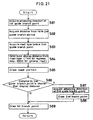
- Fig. 21 is a flow chart of processing of sector view drawing for advancing direction guidance of the present embodiment.
- Fig. 22 represents drawings for advancing direction guidance display, and
- Fig. 23 shows screens of advancing direction guidance.
- a second guide branch point P2 is at a point at shorter distance D1 from a first guide branch point P1 and the leading route is turned to rightward direction at the guide branch point P1 and to leftward direction at the guide branch point P2 as shown in Fig. 22 (a), and also a case where, as shown in Fig. 22 (b), a second guide branch point Q2 is at a position at longer distance D2 from a first guide branch point Q1, and the leading route is turned to leftward direction at the guide branch point Q1 and to rightward direction at the guide branch point Q2.
- the advancing direction of the first guide branch point (P1,Q1) is acquired from the destination direction data (Fig. 14 (E)) of the destination data shown in Fig. 14 (D) stored in the information storage unit (S81).
- the distance (D1,D2) from the first guide branch point to the second guide branch point is acquired from the guidance road data of Fig. 14 (A) (S82), and the data of road type, i.e. whether it is general road or expressway, is acquired from the road name data of Fig. 16 (B) (S83).
- a display distance is determined by the road type (S84).
- the display distance is a preset distance necessary for determining whether two advancing directions are to be displayed or not, and it is, for example, 1 km for expressway, and 300 m for general road.
- the base portion of road is drawn or visualized (S85), and it is judged whether the distance up to the second guide branch point (D1, D2) is shorter than the display distance (S86).
- the distance D1 is short as shown in Fig. 22 (a) and the guide branch point P2 is within the display distance
- the advancing direction at the second guide branch point P2 is acquired from the destination direction data (Fig. 14 (E)) of the destination data shown in Fig. 14 (D) stored in the information storage unit and it is drawn on a predetermined area. Partially overlapped on this area, the advancing direction at the first guide branch point P1 is drawn in a given area (Fig. 23 (a)).
- the distance D2 is long as shown in Fig. 22 (b) and the guide branch point Q2 is out of the display distance
- only the advancing direction at the first guide branch point Q1 is drawn in the predetermined area (Fig. 23 (b)).
- the display distance is set and information on two advancing directions is displayed only when the guide branch points are adjacent to each other. Even when the guide branch points where the vehicle should be turned are adjacent to each other, the driver can find out which way the vehicle is to be directed at-earlier chance. Thus, the driver can drive-the vehicle easily and accurately. For example, when the vehicle should be turned left immediately after right turn, the driver can drive the vehicle at ease and with full confidence.
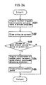
- Fig. 24 is a flow chart of a drawing processing in case the advancing direction arrows at the first guide branch point and the second guide branch point are displayed separately, and Fig. 25 shows an intersection screen.
- Fig. 25 when an intersection screen is displayed and two or more guidance data showing advancing directions are to be displayed, the number of guide branch points and the positions are acquired from the guidance road data and guidance data of Figs. 14 (A) and 14 (C) stored in the information storage unit (S91), and an arrow mark is drawn, for example, in the screen (S92). The arrow mark is drawn along the leading route and on it.
- the advancing direction guidance information is divided and drawn (S94). That is, coordinates of the middle point between the guide branch points is obtained, and heading is acquired from the destination direction data (Fig. 14 (E)) of the destination data shown in Fig. 14 (D), and the arrow is drawn at the middle point.
- the arrow mark is divided and drawn. This makes it possible to find out the advancing direction very easily and to provide reliable guidance.
- the road type and branching angle to enter the guide branch point are acquired (S101, S102).
- the road type and branching angle to enter the guide branch point are acquired (S101, S102).
- the aspect ratio For example, in case the branching angle is larger than 10 degrees in Step S103, the intersection picture is drawn with the aspect ratio still at 1:1 (Fig. 27 (a)). If the branching angle is within 10 degrees, the intersection picture is drawn by setting the aspect ratio to 2:1 (Fig. 27 (b)).
- the map should be drawn to have the size: 300 m (length) x 150 m (width).
- the drawing standard to the display screen when drawing the map is normally set to 10 dots for 100 m
- it is adjusted that only the drawing standard for lateral direction is to be set to 10 dots for 50 m.
- the road can be drawn only by widening the angle at the branching point in lateral direction. In this way, the advancing direction with narrow angle of the expressway can be displayed and clearly distinguished from the other roads.
- branching angle is narrow (small) in general road and it is difficult to find the advancing direction from the advancing direction mark.
Description
- The present invention relates to a technical field of a navigation system for vehicles for providing a driver of a vehicle with information on a route to a destination when the vehicle is driven along a route unfamiliar to the driver.
- A vehicular navigation system is a system, which searches an optimal route from the present position of the vehicle or from a specified starting point to a destination based on inputted data such as the destination data, and provides the driver with information on a route to reach the destination when the vehicle is driven along a road unfamiliar to the driver by displaying a road map on a screen of a display unit based on the suggested optimal route and by displaying the suggested route or the present position of the vehicle on the map.
- With regard to the display on the screen, a system has been known in the past, in which a route is searched from the present position of the vehicle or from a destination based on inputted data such as a destination, a transit point, etc., and a suggested route is displayed on a map or an advancing direction is displayed by an arrow on an enlarged map. Fig. 28 represents a map, which shows a route to guide the vehicle to a destination (park marked with an asterisk) via a highway shown by a white line (outlined line). Fig. 29 is an enlarged view of an area near a branch point for guiding toward a route from PARI to an airport, and an arrow indicating the advancing direction from the branch point and a message "5.0 miles; 10 minutes to the destination" is displayed.
- In a conventional type system as described above, the suggested route is drawn on a map as shown in Fig. 28, and the driver must find out the turning point and the turning direction by watching the map. Thus, it takes some time until the driver fully understands the situation. Also, in case the present position of the vehicle, the advancing direction, or the route already driven are displayed by the same magnification factor, it is difficult for the driver to discriminate the information necessary for immediate guiding from other information. Because a large number of information are displayed in addition to the information on the present position and it is not always easy to recognize the information on the present position, this is not always satisfactory in terms of recognizability. For example, in case a road is curved, it is sometimes difficult to judge whether the road is curved or not.
- Also, when an area is enlarged in the map as shown in Fig. 29, the next guide branch point is not in the displayed area, and this is inconvenient because the driver cannot find out the next turning direction after the guide branch point. To solve this problem, it has been proposed to indicate two advancing directions for adjacent intersections on the suggested route. However, by simply displaying two advancing directions, it is not easy to judge which of the advancing directions should be chosen, and it is difficult to find out the next advancing direction.
- A. Spoerri "novel route guides and displays", proceedings of the vehicle navigation and information systems conference, Ottawa, October 12-15, 1993, describes a vehicular navigation system wherein a navigation map of the current street and the next street to be traveled is displayed in respective on the screen. The travel direction of the street is displayed in due order using a directional arrow and a guidance to be performed next is displayed in the largest representation in size.
- To solve the above problems, it is an object of the present invention to provide a vehicular navigation system, by which route information near the present position of the vehicle is expressed 3-dimensionally based on the road configuration and information of the present position and of a route ahead of the present position of the vehicle is displayed as the vehicle moves, and it is possible to easily recognize information of a route immediately ahead during driving.
- A vehicular navigation system according to
Claim 1 of the present invention comprises a present position detecting means for detecting the present position of the vehicle, an input means for inputting information necessary for calculating an optimal route, a display means for displaying information for route guidance, an information memory means for storing all necessary data for route guidance including guidance road data, a route searching means for searching an optimal route based on the information inputted by said input means, a route information memory means for storing information of a route searched and suggested by said route searching means, and a guidance control means for reading two directions, i.e. a guide branch point to be guided next and a guide branch point after the next from said route information memory means based on the route searched by said route searching means and the present position detected by said present position detecting means and for outputting the information at two guide branch points to said display means under the condition that the distance between the two points is shorter than a predetermined distance, whereby said guidance control means changes drawing position of guidance information on the advancing direction at a second guide branch point based on content of the advancing direction at a first guide branch point. - It is possible according to the present invention to display information of the present position of the vehicle and a route ahead of the present position as the vehicle moves by expressing information of route near the present position of the vehicle based on configuration of roads and to easily recognize information of a route ahead during driving.
- Fig. 1 is a general block diagram showing an example of a vehicular navigation system according to the present invention;
- Fig. 2 shows data files of guidance road related to the present invention;
- Fig. 3 is a flow chart showing flow of the entire vehicular navigation system according to the present invention;
- Fig. 4 is a drawing for explaining guidance road numbe data obtained in the route searching of Fig. 3;
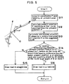
- Fig. 5 is a basic flow chart showing an embodiment of processing by a route information converting means of the present invention;
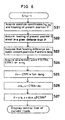
- Fig. 6 is a flow chart of processing of drawing in curved lines in Fig. 5;
- Fig. 7 is a flow chart showing processing of drawing is curved lines in Fig. 5;
- Fig. 8 is a drawing for explaining the processing of Fig. 6;
- Fig. 9 is a drawing for explaining the processing of Fig. 7;
- Fig. 10 is an illustration of an example of a screen where a road is drawn in curved lines;
- Fig. 11 is an illustration of an example of a screen where a road is drawn in straight lines;
- Fig. 12 a flow chart of another embodiment of the processing by the route information converting means of the present invention;
- Fig. 13 is a drawing for explaining data arrangement of Fig. 12;
- Fig. 14 shows examples of arrangement of major data file related to another embodiment of the present invention;
- Fig. 15 represents drawings for explaining the data file of Fig. 14;
- Fig. 16 is to explain the data file of Fig. 14;
- Fig. 17 is a flow chart showing an example of flow of the processing of a sector view drawing;
- Fig. 18 is to explain an advancing direction guidance screen;
- Fig. 19 is a flow chart for explaining a flow of processings of advancing direction guidance display;
- Fig. 20 is an illustration for explaining an example of a guidance display screen;
- Fig. 21 is a flow chart showing another example of processing of a sector view drawing;
- Fig. 22 is to explain advancing guidance display;
- Fig. 24 is a flow chart of drawing processing in case an arrow for the advancing direction is divided and displayed;
- Fig. 25 is an illustration to show a screen of an intersection;
- Fig. 26 is a flow chart of a flow to display a drawing of an intersection enlarged by two times in lateral direction;
- Fig. 27 represents a display screen enlarged by the same magnification in longitudinal and lateral directions and a display screen enlarged by two times in lateral direction;
- Fig. 28 shows an example of a leading road displayed on a map; and
- Fig. 29 is an enlarged map of an area near a guide branch point.
-
- In the following, description will be given on embodiments of the present invention referring to the drawings.
- Fig. 1 is a general block diagram of an embodiment of a vehicular navigation system according to the present invention. The vehicular navigation system according to the present invention comprises an input/
output unit 1 for inputting and outputting information relating to route guidance, a present position detecting unit (present position detecting means) 2 for detecting information relating to the present position of the vehicle, an information memory unit (information memory means) 3 for storing data of navigation necessary for calculating an optimal route guidance display and sound data required for route guidance and for storing programs (OS and/or application), and acentral processing unit 4 for performing display/sound guidance processing necessary for route search processing and route guidance and for controlling the entire system. First, description will be given on arrangement of each component. - The input/
output unit 1 is provided with function to input a destination, to specify navigation processing to thecentral processing unit 4 at the request of the driver so that guidance information is given at least by either sound or screen when the driver needs such information and also to print data after the processing. As the means for fulfilling such functions, the input unit comprises atouch switch 11 and an operation switch (input-means) for inputting the destination using telephone number or coordinates on a map or for requesting route guidance. Naturally, it may be an input unit such as a remote controller. The output unit comprises a display unit (output display means) 12 for displaying the inputted data on screen or for automatically displaying route guidance on screen upon the request of the driver, aprinter 13 for printing data processed by thecentral processing unit 4 or data stored in theinformation storage unit 3, and a speaker for outputting route guidance by means of voice. - In this case, a voice recognizing unit for inputting voice or a card reader for reading data recorded on IC card or magnetic card may be added. Also, a data communication unit may be added, by which it is possible to send or receive data to or from an information source such as a personal computer where the data specific to the driver such as map data, destination data, etc. are stored.
- The
display unit 12 comprises a color CRT and a color liquid crystal display, and all screens necessary for navigation such as route setting screen based on map data and guidance data processed by thecentral processing unit 4, a sector view screen, intersection view screen, etc. are outputted in color display. Further, buttons for setting route guidance, for guidance during route guidance and switching the screens are displayed. In particular, information on transit intersection such as name of transit intersection is outputted in pop art color display on the sector view screen. - The
display unit 12 is installed on an instrument panel near the driver's seat, and the driver can confirm the present position of the vehicle by watching the map displayed and can obtain information on the route ahead. Thedisplay unit 12 is provided with atouch switch 11 corresponding to display of functional buttons. By touching the buttons, the above operation can be executed based on the inputted signal. An input signal generating means comprising these buttons and the touch switch constitutes the input unit, but detailed description is not given here. - The present
position detecting unit 2 is to detect or receive information relating to the present position of the vehicle, and it comprises anabsolute heading sensor 24 having geomagnetic sensor and the like, arelative heading sensor 25 having steering sensor, gyro, etc., adistance sensor 26 for detecting traveled distance from number of revolutions of wheels, aGPS receiver 21 utilizing the global positioning system (GPS), and acommunication unit 5. Thecommunication unit 5 comprises aVICS receiver 22 serving as traffic information acquiring means and adata transceiver 23. VICS (Vehicle Information & Communication System) is to transmit road traffic information at real time by means of FM multiplex (character broadcasting), radio beacon, optical beacon, etc. to vehicles. FM multiplex transmits crude information to wider area, while the information transmitted by radio beacon and optical beacon is detailed information for narrow area within about 10 km in radius around the beacon, and the information is received when the vehicle passes by the beacon. VICS transmission data contains degree of traffic congestion (e.g. closed to traffic, congestion, traffic jam, heavy traffic, normal traffic, etc.), the foremost position of congestion, length of congestion, traffic restriction (information on construction, no thoroughfare, etc.), traveling time (time required at a predetermined speed). The data transceiver is, for example, a portable telephone or a personal computer, by which information necessary for navigation is sent to or received from a traffic information center (such as ATIS) at the request of the driver. - The
information storage unit 3 is an external storage unit, which stores navigation program and data in an external storage medium such as CD-ROM (hereinafter simply referred as "CD"), optical CD, IC card, etc. The program comprises a map drawing unit, a route searching unit, a route guidance unit, a present position calculating unit, a destination setting operation control unit, etc. and contains an application unit for signal processing of navigation and an OS unit. Here, programs for processing such as route searching, programs and data necessary for programs to execute display output control for route guidance and for audio output control for audio guidance, and further, display information data necessary for route guidance and map display are stored. The data stored include map data, intersection data, road data, various guidance data, and all necessary data for navigation. - More concretely, here are stored a program (route searching means) for setting a destination and a transit point based on positional information from the present
position detecting unit 2 and on input signal from theinput unit 11 and for executing route searching using the suggested road data, a program (route information converting means) for converting the suggested road data based on traffic information acquired from thecommunication unit 5 and for executing route searching again, a program for converting the suggested route to draw it 3-dimensionally, and a program for determining map drawing, map matching, audio output timing along the route and contents of voice phrase. By starting the programs stored in theinformation storage unit 3, the functions of navigation in the present invention are executed. Specifically, in the aspect of the present embodiment, programs for executing the functions of the present invention are stored in theinformation storage unit 3, which serves as an external storage medium. - The
central processing unit 4 is provided with aCPU 40 for executing various computation processings andflash memory 41 for reading and storing programs from CD of theinformation storage unit 3. Even when programs on CD are changed, theflash memory 41 erases the existing programs and make them reloadable. Further, there are provided a1st ROM 43a for storing programs to check programs of theflash memory 41 and for carrying out updating of the flash memory (program reading means), aRAM 42 for temporarily storing guidance information for the suggested route such as coordinates of the preset destination, road code number, etc. or the data under computation, and a2nd ROM 43b for storing display information data necessary for route guidance and map display. The program for updating as described above may be stored in the external storage unit. - Further, there are provided an
image memory 44 where image data used for screen display to the display unit is stored, an image processor for picking up image data from the image memory based on display control signal fromCPU 40 and for outputting it to thedisplay unit 12 after image processing, anaudio processor 46 for synthesizing voice, phrase, a sizable sentence, sound, etc. as read fromRAM 42 based on audio output control signal fromCPU 40 and sending it to thespeaker 16 after converting to analog signal, acommunication interface 47 to send or receive input/output data by communication, asensor input interface 48 for picking up sensor signal of the presentposition detecting unit 2, and aclock 49 for entering date and time to internal dialog information. - When the data acquired by sensors of the present
position detecting unit 2 is picked up by thesensor input interface 48 in thecentral processing unit 4,CPU 40 calculates coordinates of the present position at a given time interval and writes them temporarily inRAM 42. The present position coordinates are subjected to map matching by taking detection error of various data into consideration. Output values by various types of sensors are corrected and compensated at all times. The route guidance is carried out by screen display and voice output, and the driver can select whether voice output should by used or not. - Fig. 2 shows a part of the suggested (searched) road data file stored in the
information storage unit 3, i.e. the data necessary for calculating the route by the route searching unit and for carrying out the route guidance. As shown in Fig. 2 (A), the data include road number, length, road attribute data, and address and size of configuration data, and address and size of guidance data. The road number is an identification number for each of the roads included in the map classified to outward course and return course for the roads between branch points such as intersections. The road attribute data are the data showing types of the road such as overpass, underpass, expressway, national road, general road, toll road, etc. The configuration data are the data showing configuration or shape of the road. As shown in Fig. 2 (B), when each road is divided into a plurality of nodes, this includes coordinates such as east longitude or north latitude and heading data for each of the node of several meters in length. The guidance data include name of intersection (or branch point), presence or absence of traffic signal, data of landmark (such as traffic signpost, signboards of filling station, convenience store, etc.), precaution point data (such as railroad crossing, tunnel), road name data and destination data. - Fig. 3 is a flow chart for explaining flow of the entire vehicular navigation system according to the present invention. Initializing is carried out in Step S1.
CPU 40 reads navigation program from CD-ROM and stores it in theflash memory 41. Based on this navigation program, the present position is detected by the presentposition detecting unit 2, and a map of the neighborhood is displayed around the present position, and name and other data of the present position are displayed (Step S2). Next, the destination is set using telephone number, address, name of facility, registered point, etc. (Step S3), and a route from the present position to the destination is searched (Step S4). The route to reach the destination is set as guidance road number data containing guidance road numbers as shown in Fig. 4. When the route has been determined, the present position detected by the presentposition detecting unit 2 is traced, and the route up to the destination is guided and displayed (Step S5). - The present invention relates to a vehicular navigation system, in which marks such as arrows for indicating advancing direction at guide branch point or guide intersection (hereinafter referred as "guide branch point") on a leading route.
- In the vehicular navigation system of this embodiment, there is provided a guidance control means for changing display position of the advancing direction at a second guide branch point to match the advancing direction at a first guide branch point and for displaying the advancing direction at the second guide branch point at the same time. The guidance control means is provided with function to display the advancing direction at each guide branch point when the two guide branch points are adjacent to each other at a distance shorter than the predetermined distance and also with function to highlight or emphasize guidance information of advancing direction of the first guide branch point. The guidance control means is also provided with function to display the advancing direction guidance information at the first guide branch point at upper center of the display screen and to display the advancing direction guidance information at the second and subsequent guide branch points at upper right or left of the display screen or to overlap the guide branch points one after another with the nearer point on the upper layer.
- In the vehicular navigation system of the present invention, display position of the advancing direction at the second guide branch point is changed according to the advancing direction at the first guide branch point. As a result, when the driver recognizes the advancing direction guidance at the next guide branch point, the driver can recognize the advancing direction guidance information of the guide branch point after the next. Because advancing direction at each guide branch point is displayed when the distance between the guide branch points is short, it is easily recognized that the guide branch points are adjacent to each other. For example, when the vehicle must be turned left immediately after turning to right, the driver can drive the vehicle at ease. By highlighting or emphasizing the advancing direction guidance of the first guide branch point, the driver can easily recognize the next advancing direction guidance. By overlapping the advancing direction guidance of the first guide branch point with emphasis, priority of guidance is more clearly indicated, and the driver can easily recognize the next guidance. In the guidance of the advancing direction, the advancing direction guidance information at the first guide branch point is displayed at upper center of the display screen, and the advancing direction guidance information at the second and subsequent guide branch points is displayed at upper right or left of the display screen with the nearer guide branch point on the upper layer. Every time the vehicle passes through a guide branch point, the uppermost advancing direction guidance information (i.e. on top of the others) is moved to upper center of the display screen as the advancing direction guidance at the first guide branch point. When the vehicle approaches the destination, the driver can recognize the number of turning points where the vehicle is to be turned has decreased because the remaining layers of the advancing direction guidances displayed on the screen have decreased.
- Fig. 14 to Fig. 16 show examples of major data files stored in the
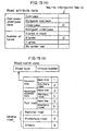
information storage unit 3 of Fig. 1 according to the present embodiment. Fig. 14 (A) represents guidance road data file, in which route has been searched by the route searching means and the data necessary for route guidance is stored. For each of the number of roads (n), it consists of various data such as road number, length, road attribute data, address and size of configuration data, and address and size of guidance data. The road number is set for each direction (outward course and return course) and for each road between branch points. The road attribute data serving as road guidance auxiliary information data include the data indicating that the road is overpass, road alongside overpass, underpass, or road alongside underpass, and information on number of lanes a shown in Fig. 15 (A). The configuration data contain coordinate data including east longitude and north latitude to each of several meters of the node when each road is divided into a plurality of nodes as shown in Fig. 14 (B). - The guidance data include the data such as name of intersection (or branch point, precaution point data, road -name data, address and size of road name voice data, and address and size of destination data. The precaution data are the data indicating railroad crossing, tunnel entrance, tunnel exit, road width narrowing point etc., warning the driver at railroad crossing, tunnel, etc. other than the branch point as shown in Fig. 16 (A). The road name data indicate information of the type of road such as expressway, municipal expressway, toll road, general road (national road, prefectural road, other road), and indicating information such as main line or approach road for expressway, municipal expressway and toll road as shown in Fig. 15 (B).
- The data comprise the road type data and in-type number, i.e. individual number data for each road type.
- The destination data are the data such as destination road number, destination name, address and size of destination name voice data, destination direction data, and driving guidance data as shown in Fig. 14 (D). The destination direction data indicate information such as "invalid" (destination direction is not used), "unnecessary" (no guidance is necessary), "go straight ahead", right ward direction, diagonally rightward direction, direction to return to right, leftward direction, diagonally leftward direction, and direction to return to left. The driving guidance data include the data for guiding as to which lane the vehicle should be driven along when there are a plurality of lanes as shown in Fig. 16 (B), indicating information such as bear right, bear left, bear toward the center or no suggestion.
- Next, description will be given on the flow of processings of the vehicular navigation system of the present invention. Fig. 17 is a flow chart of the processing to draw a sector view for advancing direction guidance, and Fig. 18 shows advancing direction guidance screens. The present embodiment is characterized in that, based on the advancing direction at the first guide branch point, the position to draw or visualize the advancing direction guidance information at the second guide branch point is changed.
- Explaining the drawing processing, from the destination direction data (Fig. 14 (E)) of the destination data shown in Fig. 14 (D) stored in the information storage unit, advancing directions at the first and the second guide branch points are acquired (S61, S62), and base portion of the road is drawn at the center of the screen (S63). Then, based on the advancing direction at the first guide branch point, drawing point of the second guide branch point is determined (S64), and the advancing direction (arrow mark in Fig. 18) at the second guide branch point is drawn at this position (S65). Next, the advancing direction at the first guide branch point is drawn by partially overlapping on the advancing direction at the second guide branch point at the upper center of the screen (on the road) (S66). For example, in case the advancing direction at the first guide branch point is rightward direction as shown in Fig. 18 (a), drawing position of the second guide branch point is determined at right or at upper right ahead of the advancing direction. As shown in Fig. 18 (b), in case the advancing direction at the first guide branch point is a direction straight ahead, the drawing position of the second guide branch point is determined at upper position ahead of the arrow of the advancing direction. In case the advancing direction at the first guide branch point is leftward direction as shown in Fig. 18 (c), the drawing position of the second guide branch point is determined at upper left ahead of the advancing direction.
- In this way, the drawing position of the second guide branch point is determined based on the advancing direction at the first guide branch point, and, when the driver recognizes the next guidance, it is possible to recognize the guidance information after the next. Also, as shown in Fig. 18, the first advancing direction mark is partially overlapped and displayed on the second advancing direction mark. Because the first advancing direction guidance is displayed with highlight or emphasis, priority of the advancing direction guidance information can be clearly seen, and the next advancing direction guidance can be easily recognized. As the method to emphasize, various methods can be adopted in addition to overlapping display, e.g. displaying the first advancing direction mark in larger size, with thicker line, by changing color, with different pattern, or by flashing display.
- Next, description will be given on sequential overwriting of advancing direction guidances up to the destination referring to Fig. 19 and Fig. 20. In this example, display positions of the advancing direction guidance mark is at the position as explained in Fig. 17 and Fig. 18. Fig. 19 is a flow chart of display processing of advancing direction guidance, and Fig. 20 represents a screen displayed by the display processing.
- In Fig. 19, advancing direction at all guide branch points up to the destination are acquired from the destination direction data (Fig. 14 (E)) of the destination data shown in Fig. 14 (D) stored in the information storage unit (S71), and the advancing directions are written in layers at the first predetermined position with the advancing direction at the guide branch point nearest to the present position placed at the uppermost layer (S72). By this processing, the advancing direction on the uppermost layer is indicated by a left turn mark as shown at upper right of the display screen in the example of Fig. 20, and it is clear from the display that the advancing direction marks of the subsequent guide branch points are all under it one after another. The road is displayed at the center of the screen, and the present position is indicated by a mark Δ encircled by O.
- Then, the advancing direction of the next guide branch point is displayed at a second predetermined position (S73). By this processing, a right turn arrow at the next guide branch point is displayed at upper center of the screen in the example of Fig. 20. A part of the area of the right turn arrow mark for guiding the advancing direction at the next guide branch point is partially overlapped on the area of the next left turn arrow mark, and the next advancing direction guidance mark is displayed with emphasis. By the present position detecting unit, the position of the vehicle is traced, and it is judged whether the vehicle reached the destination or not. Until it reaches the destination and each time the passing of the guide branch point is detected, the screen is updated, and advancing direction guiding marks at the next guide branch point and the guide branch point after the next are displayed newly. Updating of the screen is executed, for example, as follows: The advancing direction mark of the second predetermined position displayed so far is erased, and the advancing direction mark of the next guide branch point is displayed newly at the second predetermined position. At the same time, the advancing direction guiding mark of the next guide branch point is displayed at the first predetermined position.
- In the example of Fig. 20, the advancing direction mark at the guide branch point after the next is overlapped in layers up to the destination, and by counting the number of layers on the screen, it is possible to find out the number of the guide branch points to be driven through. Therefore, by counting the number of the remaining layers of the advancing direction mark after the next, it is possible to recognize the number of turning points where the vehicle is to be turned has decreased when the vehicle approaches the destination. When only one advancing direction guiding mark is left, the information (mark) of the destination is finally displayed, and display processing of the advancing direction guidance is completed when the vehicle reaches the destination.
- Fig. 21 is a flow chart of processing of sector view drawing for advancing direction guidance of the present embodiment. Fig. 22 represents drawings for advancing direction guidance display, and Fig. 23 shows screens of advancing direction guidance.
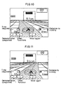
- Description is given now on a case where, as shown in Fig. 22 (a), a second guide branch point P2 is at a point at shorter distance D1 from a first guide branch point P1 and the leading route is turned to rightward direction at the guide branch point P1 and to leftward direction at the guide branch point P2 as shown in Fig. 22 (a), and also a case where, as shown in Fig. 22 (b), a second guide branch point Q2 is at a position at longer distance D2 from a first guide branch point Q1, and the leading route is turned to leftward direction at the guide branch point Q1 and to rightward direction at the guide branch point Q2.
- In the processing of Fig. 21, the advancing direction of the first guide branch point (P1,Q1) is acquired from the destination direction data (Fig. 14 (E)) of the destination data shown in Fig. 14 (D) stored in the information storage unit (S81). Next, the distance (D1,D2) from the first guide branch point to the second guide branch point is acquired from the guidance road data of Fig. 14 (A) (S82), and the data of road type, i.e. whether it is general road or expressway, is acquired from the road name data of Fig. 16 (B) (S83). Then, a display distance is determined by the road type (S84). The display distance is a preset distance necessary for determining whether two advancing directions are to be displayed or not, and it is, for example, 1 km for expressway, and 300 m for general road.
- Next, the base portion of road is drawn or visualized (S85), and it is judged whether the distance up to the second guide branch point (D1, D2) is shorter than the display distance (S86). For example, in case the distance D1 is short as shown in Fig. 22 (a) and the guide branch point P2 is within the display distance, the advancing direction at the second guide branch point P2 is acquired from the destination direction data (Fig. 14 (E)) of the destination data shown in Fig. 14 (D) stored in the information storage unit and it is drawn on a predetermined area. Partially overlapped on this area, the advancing direction at the first guide branch point P1 is drawn in a given area (Fig. 23 (a)). On the other hand, in case the distance D2 is long as shown in Fig. 22 (b) and the guide branch point Q2 is out of the display distance, only the advancing direction at the first guide branch point Q1 is drawn in the predetermined area (Fig. 23 (b)).
- As described above, the display distance is set and information on two advancing directions is displayed only when the guide branch points are adjacent to each other. Even when the guide branch points where the vehicle should be turned are adjacent to each other, the driver can find out which way the vehicle is to be directed at-earlier chance. Thus, the driver can drive-the vehicle easily and accurately. For example, when the vehicle should be turned left immediately after right turn, the driver can drive the vehicle at ease and with full confidence.
- Next, description will be given on advancing direction guidance when there is a guide branch point in intersection screen, referring to Fig. 24 and Fig. 25. Fig. 24 is a flow chart of a drawing processing in case the advancing direction arrows at the first guide branch point and the second guide branch point are displayed separately, and Fig. 25 shows an intersection screen.
- As shown is Fig. 25, when an intersection screen is displayed and two or more guidance data showing advancing directions are to be displayed, the number of guide branch points and the positions are acquired from the guidance road data and guidance data of Figs. 14 (A) and 14 (C) stored in the information storage unit (S91), and an arrow mark is drawn, for example, in the screen (S92). The arrow mark is drawn along the leading route and on it. In case there are two or more guide branch points in the arrow drawn in Step S93, the advancing direction guidance information is divided and drawn (S94). That is, coordinates of the middle point between the guide branch points is obtained, and heading is acquired from the destination direction data (Fig. 14 (E)) of the destination data shown in Fig. 14 (D), and the arrow is drawn at the middle point. As a result, the arrow mark is divided and drawn. This makes it possible to find out the advancing direction very easily and to provide reliable guidance.
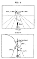
- Next, description will be given on a case where guide branching at narrow (smaller) angle on expressway is displayed for easy understanding, referring to Fig. 26 and Fig. 27. On expressway, when the road is branched at narrow (smaller) angle, even when the advancing direction as explained above is displayed, it is often difficult to judge which road the advancing direction indicates. In such case, the narrow angle may be displayed by widening it in lateral direction of the screen.
- From the guidance road data of Fig. 14 (A) stored in the information storage unit and the road name data of Fig. 14 (B), the road type and branching angle to enter the guide branch point are acquired (S101, S102). Next, under the condition that it is branched off from expressway and that branching angles of all roads departing from the branch point are narrow, it is drawn by changing the aspect ratio. For example, in case the branching angle is larger than 10 degrees in Step S103, the intersection picture is drawn with the aspect ratio still at 1:1 (Fig. 27 (a)). If the branching angle is within 10 degrees, the intersection picture is drawn by setting the aspect ratio to 2:1 (Fig. 27 (b)). For example, if it is supposed that a map is drawn normally on the display screen at a size of 300 m (length) x 300 m (width), and if the aspect ratio is changed to 2:1, the map should be drawn to have the size: 300 m (length) x 150 m (width). For this purpose, if it is supposed that the drawing standard to the display screen when drawing the map is normally set to 10 dots for 100 m, it is adjusted that only the drawing standard for lateral direction is to be set to 10 dots for 50 m. If the positions of the nodes to form the road are determined when the map is drawn and the road is drawn with sufficient widths in both directions with the line connecting the nodes as the central line, the road can be drawn only by widening the angle at the branching point in lateral direction. In this way, the advancing direction with narrow angle of the expressway can be displayed and clearly distinguished from the other roads. In the above, explanation has been given on the application to expressway, while it is needless to say that this can also be applied to the case where branching angle is narrow (small) in general road and it is difficult to find the advancing direction from the advancing direction mark.
Claims (9)
- A vehicular navigation system comprising:a present position detecting means (2) for detecting the present position of the vehicle;an input means for inputting information necessary for searching an optimal route;a display means (12) for displaying information for route guidance;an information memory means (3) for storing all data necessary for route guidance including guidance road data;a route searching means for searching a route based on the information inputted by said input means;a route information memory means (42) for storing information of the route searched by said route searching means; anda guidance control means for reading two advancing directions, i.e. an advancing direction at a guide branch point to be guided next by said route information memory means and an advancing direction of a guide branch point after the next based on the route searched by the route searching means and the present position detected by said present position detecting means (2), and outputs the advancing direction guiding information at two guide branch points to said display means (12) under the condition that the distance between the two guide branch points is shorter than a predetermined distance , whereby:said guidance control means changes drawing position of the advancing direction guiding information at the second guide branch point based on content of advancing direction at the first guide branch point.
- A vehicular navigation system according to Claim 1 , wherein the next necessary advancing direction guidance is easily recognized by displaying and emphasizing the advancing direction guiding information at the first guide branch point.
- A system according to of Claims 1 or 2, wherein said display of the advancing direction guiding information at the first guide branch point is to overlap the advancing direction guiding information at the first guide branch point on the advancing direction guiding information at the second guide branch point.
- A system according to any one of Claims 1 to 3, wherein the emphasized display of the advancing direction guiding information at the first guide branch point is to display the advancing direction guiding information at the first guide branch point by displaying larger marks, by displaying with thicker lines, by changing colors, by turning to patterns or by flashing display.
- A system according to any one of Claims 1 to 4, wherein said display means (12) displays the advancing direction guiding information at the first guide branch point at upper center of the display screen, and displays by overlapping the advancing direction guiding information of the second and subsequent guide branch points at upper right or left of the display screen or by sequentially overlapping the information of the nearer guide branch point on the other.
- A system according to any one of Claims 1 to 5, wherein advancing direction guiding information at the first guide branch point and advancing direction guiding information at the second and subsequent guide branch points separately on the display screen.
- A vehicular navigation system according to any one of Claims 1 to 6, wherein, in case a road is branched off at a guide branch point at a narrow angle, the road is drawn by widening the angle.
- A system according to any one of Claims 1 to 7, wherein said information memory means (3) is an external storage medium, and a program for controlling navigation operation is stored in addition to said road data.
- A vehicular navigation system according to Claim 8, wherein said program includes a program for converting the route information near the present position of the vehicle to a visually 3-dimensional route information.
Applications Claiming Priority (6)
| Application Number | Priority Date | Filing Date | Title |
|---|---|---|---|
| JP21786695A JP3491786B2 (en) | 1995-08-25 | 1995-08-25 | Vehicle navigation system |
| JP217866/95 | 1995-08-25 | ||
| JP21786695 | 1995-08-25 | ||
| JP10792196 | 1996-04-26 | ||
| JP107921/96 | 1996-04-26 | ||
| JP10792196A JP3570457B2 (en) | 1996-04-26 | 1996-04-26 | Vehicle navigation system |
Publications (2)
| Publication Number | Publication Date |
|---|---|
| EP0762361A1 EP0762361A1 (en) | 1997-03-12 |
| EP0762361B1 true EP0762361B1 (en) | 2003-05-14 |
Family
ID=26447878
Family Applications (1)
| Application Number | Title | Priority Date | Filing Date |
|---|---|---|---|
| EP96113536A Expired - Lifetime EP0762361B1 (en) | 1995-08-25 | 1996-08-23 | Navigation system for vehicles |
Country Status (3)
| Country | Link |
|---|---|
| US (1) | US5874905A (en) |
| EP (1) | EP0762361B1 (en) |
| DE (1) | DE69628102T2 (en) |
Families Citing this family (136)
| Publication number | Priority date | Publication date | Assignee | Title |
|---|---|---|---|---|
| US6067500A (en) * | 1995-08-14 | 2000-05-23 | Aisin Aw Co., Ltd. | Navigation system |
| KR100267543B1 (en) * | 1996-04-28 | 2000-10-16 | 모리 하루오 | Device for processing road data or intersection data |
| JP3322137B2 (en) * | 1996-08-29 | 2002-09-09 | 株式会社デンソー | Vehicle navigation device |
| JP3876463B2 (en) * | 1996-11-18 | 2007-01-31 | ソニー株式会社 | Map information providing apparatus and method |
| JP3876462B2 (en) * | 1996-11-18 | 2007-01-31 | ソニー株式会社 | Map information providing apparatus and method |
| JP3474380B2 (en) * | 1996-12-12 | 2003-12-08 | 株式会社ザナヴィ・インフォマティクス | Navigation device and map database device |
| EP0901676B1 (en) * | 1997-02-07 | 2008-01-09 | Casio Computer Co., Ltd. | Network system for serving information to mobile terminal apparatus |
| JPH10300487A (en) * | 1997-04-22 | 1998-11-13 | Mitsubishi Electric Corp | Traffic information display device |
| US6212472B1 (en) * | 1997-09-04 | 2001-04-03 | Visteon Technologies, Llc | Method and apparatus for displaying current vehicle position |
| JP2003521672A (en) * | 1998-04-30 | 2003-07-15 | ヴィステオン・テクノロジーズ・エルエルシイ | Visually Reducible Intersection Representation Method for Vehicle Navigation |
| JP3473398B2 (en) * | 1998-05-01 | 2003-12-02 | 株式会社日立製作所 | Map application system and map display control method |
| JP2000039334A (en) * | 1998-05-21 | 2000-02-08 | Sony Corp | Information processing device, method and providing medium |
| US6362751B1 (en) * | 1998-06-11 | 2002-03-26 | Magellan Dis, Inc. | Navigation system with a route exclusion list system |
| US6356840B2 (en) * | 1998-06-12 | 2002-03-12 | Mitsubishi Denki Kabushiki Kaisha | Navigation device with a three dimensional display |
| EP1008834B1 (en) * | 1998-06-12 | 2009-11-25 | Mitsubishi Denki Kabushiki Kaisha | Navigation device |
| DE19840120C2 (en) * | 1998-09-03 | 2001-01-11 | Mannesmann Vdo Ag | Navigation system for additional display of directional information |
| JP3831171B2 (en) * | 1999-05-06 | 2006-10-11 | 日産自動車株式会社 | Vehicle notification device |
| JP3475123B2 (en) * | 1999-05-24 | 2003-12-08 | アイシン・エィ・ダブリュ株式会社 | Navigation device and storage medium |
| DE19933504A1 (en) * | 1999-07-16 | 2001-01-25 | Bayerische Motoren Werke Ag | Method for the graphical representation of a road ahead |
| DE19933503A1 (en) * | 1999-07-16 | 2001-01-25 | Bayerische Motoren Werke Ag | Method for the graphical representation of a road ahead |
| JP3481168B2 (en) * | 1999-08-27 | 2003-12-22 | 松下電器産業株式会社 | Digital map location information transmission method |
| JP3994365B2 (en) * | 1999-09-03 | 2007-10-17 | アイシン・エィ・ダブリュ株式会社 | Navigation device and storage medium |
| JP3908419B2 (en) * | 1999-09-14 | 2007-04-25 | アルパイン株式会社 | Navigation device |
| IL132046A (en) * | 1999-09-23 | 2006-04-10 | Destinator Technologies Inc Ca | Cartographic display accelerator method |
| US6516273B1 (en) | 1999-11-04 | 2003-02-04 | Veridian Engineering, Inc. | Method and apparatus for determination and warning of potential violation of intersection traffic control devices |
| JP3455153B2 (en) * | 2000-02-16 | 2003-10-14 | 松下電器産業株式会社 | Lane guidance display method at intersection, navigation device thereof, and recording medium |
| US6621423B1 (en) | 2000-03-06 | 2003-09-16 | Sony Corporation | System and method for effectively implementing an electronic visual map device |
| US6282486B1 (en) | 2000-04-03 | 2001-08-28 | International Business Machines Corporation | Distributed system and method for detecting traffic patterns |
| US6349246B1 (en) | 2000-04-24 | 2002-02-19 | International Business Machines Corporation | Preemptive control of a vehicle computer system based on local and environmental sensing |
| US6650253B2 (en) * | 2000-05-30 | 2003-11-18 | Matsushita Electric Industrial Co., Ltd. | Map display device, map display method, and computer program for use in map display device |
| FI20001374A0 (en) | 2000-06-09 | 2000-06-09 | Arcus Software Oy | Method for Communicating Data and Memory Capacity of a Workstation Using a 3D Model |
| US20070042790A1 (en) * | 2000-07-14 | 2007-02-22 | Norman Mohi | Locating system and method |
| US6292745B1 (en) * | 2000-07-24 | 2001-09-18 | Navigation Technologies Corp. | Method and system for forming a database of geographic data for distribution to navigation system units |
| US20030078729A1 (en) * | 2000-08-04 | 2003-04-24 | Eriko Ohdachi | Route guide information generator, route guide information generating method, and navigation system |
| US6600982B1 (en) | 2000-08-23 | 2003-07-29 | International Business Machines Corporation | System, method and article of manufacture to provide output according to trip information |
| US6622087B2 (en) | 2000-12-26 | 2003-09-16 | Intel Corporation | Method and apparatus for deriving travel profiles |
| JP4557238B2 (en) | 2001-02-06 | 2010-10-06 | 本田技研工業株式会社 | Directional guidance device for motorcycles |
| DE10109045B4 (en) * | 2001-02-24 | 2019-11-21 | Harman Becker Automotive Systems (Xsys Division) Gmbh | Method for displaying high-quality route guide symbols |
| US6574549B2 (en) * | 2001-03-09 | 2003-06-03 | International Business Machines Corporation | Method and system for the visually impaired to navigate a route through a facility |
| US6600994B1 (en) | 2001-05-17 | 2003-07-29 | Horizon Navigation, Inc. | Quick selection of destinations in an automobile navigation system |
| DE10138719A1 (en) | 2001-08-07 | 2003-03-06 | Siemens Ag | Method and device for displaying driving instructions, especially in car navigation systems |
| JP3599698B2 (en) * | 2001-10-03 | 2004-12-08 | 怡利電子工業股▲ふん▼有限公司 | Pointer type car navigation screen display method |
| JP2003161624A (en) * | 2001-11-28 | 2003-06-06 | Alpine Electronics Inc | Navigation system and intersection guiding method |
| US6704645B1 (en) | 2001-12-11 | 2004-03-09 | Garmin Ltd. | System and method for estimating impedance time through a road network |
| US7283905B1 (en) | 2001-12-11 | 2007-10-16 | Garmin Ltd. | System and method for estimating impedance time through a road network |
| US6574554B1 (en) * | 2001-12-11 | 2003-06-03 | Garmin Ltd. | System and method for calculating a navigation route based on non-contiguous cartographic map databases |
| US6545637B1 (en) | 2001-12-20 | 2003-04-08 | Garmin, Ltd. | Systems and methods for a navigational device with improved route calculation capabilities |
| US6581003B1 (en) * | 2001-12-20 | 2003-06-17 | Garmin Ltd. | Systems and methods for a navigational device with forced layer switching based on memory constraints |
| US6892135B1 (en) | 2001-12-21 | 2005-05-10 | Garmin Ltd. | Navigation system, method and device with automatic next turn page |
| US6975940B1 (en) | 2001-12-21 | 2005-12-13 | Garmin Ltd. | Systems, functional data, and methods for generating a route |
| US7277794B1 (en) | 2001-12-21 | 2007-10-02 | Garmin Ltd. | Guidance with feature accounting for insignificant roads |
| US6847890B1 (en) | 2001-12-21 | 2005-01-25 | Garmin Ltd. | Guidance with feature accounting for insignificant roads |
| US6999873B1 (en) | 2001-12-21 | 2006-02-14 | Garmin Ltd. | Navigation system, method and device with detour algorithm |
| US7184886B1 (en) | 2001-12-21 | 2007-02-27 | Garmin Ltd. | Navigation system, method and device with detour algorithm |
| US6751549B1 (en) | 2002-01-17 | 2004-06-15 | Navigation Technologies Corporation | Method and system for route calculation that avoids railroad crossings |
| DE10203891A1 (en) * | 2002-01-31 | 2003-08-21 | Francesco Marin | Information display system for traffic information, e.g. weather or road hazards, has input indicating conditions and in-vehicle display |
| US6873905B2 (en) * | 2002-03-19 | 2005-03-29 | Opnext Japan, Inc. | Communications type navigation device |
| JP4031282B2 (en) * | 2002-04-17 | 2008-01-09 | 株式会社ザナヴィ・インフォマティクス | Navigation device and navigation control program |
| DE10225782B4 (en) * | 2002-06-10 | 2005-04-07 | Daimlerchrysler Ag | Method for informing road users |
| US6771189B2 (en) * | 2002-07-17 | 2004-08-03 | Alpine Electronics, Inc. | Display method and apparatus for navigation system |
| KR20040064634A (en) * | 2003-01-10 | 2004-07-19 | 가부시끼가이샤 히다치 세이사꾸쇼 | Display method of naviserver and navigation |
| US20060212185A1 (en) * | 2003-02-27 | 2006-09-21 | Philp Joseph W | Method and apparatus for automatic selection of train activity locations |
| KR100811232B1 (en) * | 2003-07-18 | 2008-03-07 | 엘지전자 주식회사 | Turn-by-turn navigation system ? next guidance way |
| US7216037B2 (en) * | 2003-09-10 | 2007-05-08 | International Business Machines Corporation | Method and system for logistics quality of service measurements using GPS |
| EP1544829B1 (en) * | 2003-12-19 | 2017-02-15 | Samsung Electronics Co., Ltd. | Navigation system and navigation method |
| JP4281559B2 (en) * | 2004-01-15 | 2009-06-17 | 株式会社デンソー | Navigation device |
| US20050177305A1 (en) * | 2004-02-06 | 2005-08-11 | Han Maung W. | Display method and apparatus for navigation system |
| GB2437988B (en) * | 2004-03-15 | 2008-10-01 | Tomtom Bv | GPS navigation device |
| CA2559726C (en) | 2004-03-24 | 2015-10-20 | A9.Com, Inc. | System and method for displaying images in an online directory |
| JP4423114B2 (en) * | 2004-06-02 | 2010-03-03 | アルパイン株式会社 | Navigation device and its intersection guidance method |
| EP1751499B1 (en) * | 2004-06-03 | 2012-04-04 | Making Virtual Solid, L.L.C. | En-route navigation display method and apparatus using head-up display |
| JP4508728B2 (en) * | 2004-06-07 | 2010-07-21 | アルパイン株式会社 | In-vehicle electronic device and display method of digital broadcast in the device |
| JP4722433B2 (en) * | 2004-08-25 | 2011-07-13 | アルパイン株式会社 | Car navigation system |
| US7376510B1 (en) * | 2004-11-05 | 2008-05-20 | Navteq North America, Llc | Map display for a navigation system |
| KR101047719B1 (en) * | 2005-02-16 | 2011-07-08 | 엘지전자 주식회사 | Method and device for driving route guidance of moving object in navigation system |
| US7647565B2 (en) * | 2005-02-16 | 2010-01-12 | International Business Machines Coporation | Method, apparatus, and computer program product for an enhanced mouse pointer |
| JP4483798B2 (en) * | 2005-04-06 | 2010-06-16 | 株式会社デンソー | Route guidance apparatus and program |
| US7624358B2 (en) * | 2005-04-25 | 2009-11-24 | International Business Machines Corporation | Mouse radar for enhanced navigation of a topology |
| US8670925B2 (en) * | 2005-06-21 | 2014-03-11 | Calabrese Holdings L.L.C. | Navigation system and method |
| US9726513B2 (en) * | 2005-06-21 | 2017-08-08 | Nytell Software LLC | Navigation system and method |
| US7711478B2 (en) * | 2005-06-21 | 2010-05-04 | Mappick Technologies, Llc | Navigation system and method |
| JP4682732B2 (en) * | 2005-07-27 | 2011-05-11 | 株式会社デンソー | Navigation device |
| JP4783603B2 (en) * | 2005-08-26 | 2011-09-28 | 株式会社デンソー | MAP DISPLAY DEVICE, MAP DISPLAY METHOD, MAP DISPLAY PROGRAM, AND RECORDING MEDIUM CONTAINING THE PROGRAM |
| WO2007047485A1 (en) * | 2005-10-14 | 2007-04-26 | Yahoo! Inc. | Interactive mapping method and system |
| GB0523512D0 (en) * | 2005-11-18 | 2005-12-28 | Applied Generics Ltd | Enhancing traffic and navigation information with visual and audio data |
| US20070143676A1 (en) * | 2005-12-20 | 2007-06-21 | Taiwan Online Co., Ltd. | Electronic map with a drawing feature |
| US7925320B2 (en) * | 2006-03-06 | 2011-04-12 | Garmin Switzerland Gmbh | Electronic device mount |
| WO2007105540A1 (en) * | 2006-03-10 | 2007-09-20 | Pioneer Corporation | Navigation device and navigation method |
| KR20070093484A (en) * | 2006-03-14 | 2007-09-19 | 주식회사 현대오토넷 | Apparatus for displaying traffic lane guide image of navigation using vehicle |
| JP2008009915A (en) * | 2006-06-30 | 2008-01-17 | Pioneer Electronic Corp | Road sign determination device, method and program therefor |
| EP2110797B1 (en) * | 2006-12-05 | 2015-10-07 | Fujitsu Limited | Traffic situation display method, traffic situation display system, vehicle-mounted device, and computer program |
| JPWO2008099483A1 (en) * | 2007-02-15 | 2010-05-27 | パイオニア株式会社 | Display control apparatus, display control method, display control program, and recording medium |
| DE102007030345A1 (en) * | 2007-02-28 | 2008-09-04 | Navigon Ag | Navigation device and method for the graphic output of navigation instructions |
| US8467962B2 (en) * | 2007-03-23 | 2013-06-18 | Mitsubishi Electric Corporation | Navigation system and lane information display method |
| US8229458B2 (en) | 2007-04-08 | 2012-07-24 | Enhanced Geographic Llc | Systems and methods to determine the name of a location visited by a user of a wireless device |
| DE102007023765A1 (en) * | 2007-05-22 | 2008-11-27 | Robert Bosch Gmbh | Method and arrangement for outputting route guidance information |
| DE102007027756A1 (en) * | 2007-06-16 | 2008-12-18 | Bayerische Motoren Werke Aktiengesellschaft | A method for assisting a driver of a motor vehicle in the passage of the motor vehicle through a bottleneck and / or to maintain a safety distance to the front vehicle |
| US8554475B2 (en) | 2007-10-01 | 2013-10-08 | Mitac International Corporation | Static and dynamic contours |
| JP4561802B2 (en) * | 2007-10-02 | 2010-10-13 | 株式会社デンソー | Map display device and program |
| US20110288766A1 (en) * | 2008-01-29 | 2011-11-24 | Increment P Corporation | Navigation device, navigation method, navigation program, and recording medium |
| KR20100010298A (en) * | 2008-07-22 | 2010-02-01 | 삼성전자주식회사 | Method and appartus for guiding path |
| US8990004B2 (en) * | 2008-12-17 | 2015-03-24 | Telenav, Inc. | Navigation system with query mechanism and method of operation thereof |
| JP2011064501A (en) * | 2009-09-15 | 2011-03-31 | Sony Corp | Navigation apparatus, navigation method, and cellular phone with navigation function |
| US8725407B2 (en) * | 2009-11-09 | 2014-05-13 | United Parcel Service Of America, Inc. | Enhanced location information for points of interest |
| DE102010001684A1 (en) * | 2010-02-09 | 2011-08-11 | Robert Bosch GmbH, 70469 | Method for operating a head-up display system, head-up display system |
| US8286437B2 (en) * | 2010-06-30 | 2012-10-16 | Thermo King Corporation | Transport refrigeration system with predictive refrigeration |
| EP2431712B1 (en) * | 2010-09-17 | 2013-05-01 | Kapsch TrafficCom AG | Method for calculating the distance travelled by a vehicle |
| DE102010052000A1 (en) * | 2010-11-19 | 2012-05-24 | Bayerische Motoren Werke Aktiengesellschaft | Method for issuing navigation instructions |
| DE102011118161B3 (en) * | 2011-11-10 | 2013-03-28 | Audi Ag | Method for determining position |
| KR101318651B1 (en) * | 2011-11-15 | 2013-10-16 | 현대자동차주식회사 | Navigation System and Displaying Method Thereof |
| USD719973S1 (en) * | 2012-06-06 | 2014-12-23 | Apple Inc. | Display screen or portion thereof with graphical user interface |
| CA2877453A1 (en) | 2012-06-21 | 2013-12-27 | Cellepathy Ltd. | Device context determination |
| US9638537B2 (en) | 2012-06-21 | 2017-05-02 | Cellepathy Inc. | Interface selection in navigation guidance systems |
| US20150177010A1 (en) * | 2013-08-23 | 2015-06-25 | Cellepathy Ltd. | Suppressed navigation instructions |
| JP6018881B2 (en) * | 2012-11-07 | 2016-11-02 | 株式会社日立製作所 | Navigation device and navigation method |
| USD750663S1 (en) | 2013-03-12 | 2016-03-01 | Google Inc. | Display screen or a portion thereof with graphical user interface |
| US8676431B1 (en) | 2013-03-12 | 2014-03-18 | Google Inc. | User interface for displaying object-based indications in an autonomous driving system |
| USD754190S1 (en) * | 2013-03-13 | 2016-04-19 | Google Inc. | Display screen or portion thereof with graphical user interface |
| USD754189S1 (en) * | 2013-03-13 | 2016-04-19 | Google Inc. | Display screen or portion thereof with graphical user interface |
| CN105765346B (en) * | 2014-01-28 | 2019-09-10 | 爱信艾达株式会社 | Map display system, method and recording medium |
| US9459115B1 (en) * | 2014-03-28 | 2016-10-04 | Amazon Technologies, Inc. | Unobstructed map navigation using animation |
| US10066959B2 (en) | 2014-09-02 | 2018-09-04 | Apple Inc. | User interactions for a mapping application |
| US9911338B2 (en) | 2014-10-31 | 2018-03-06 | Aircraft Owners And Pilots Association | Comprehensive flight planning tool |
| EP3484134B1 (en) | 2015-02-02 | 2022-03-23 | Apple Inc. | Device, method, and graphical user interface for establishing a relationship and connection between two devices |
| USD812077S1 (en) * | 2015-12-30 | 2018-03-06 | Faraday & Future Inc. | Display screen with graphical user interface |
| US10730626B2 (en) | 2016-04-29 | 2020-08-04 | United Parcel Service Of America, Inc. | Methods of photo matching and photo confirmation for parcel pickup and delivery |
| US9957048B2 (en) | 2016-04-29 | 2018-05-01 | United Parcel Service Of America, Inc. | Unmanned aerial vehicle including a removable power source |
| AU2017100667A4 (en) | 2016-06-11 | 2017-07-06 | Apple Inc. | Activity and workout updates |
| US11816325B2 (en) | 2016-06-12 | 2023-11-14 | Apple Inc. | Application shortcuts for carplay |
| US10775792B2 (en) | 2017-06-13 | 2020-09-15 | United Parcel Service Of America, Inc. | Autonomously delivering items to corresponding delivery locations proximate a delivery route |
| JP6692324B2 (en) * | 2017-06-19 | 2020-05-13 | 三菱重工業株式会社 | Control device, control system, moving body, control method and program |
| USD883302S1 (en) * | 2018-09-14 | 2020-05-05 | Lyft, Inc. | Display device with an animated graphical interface |
| DE102019204036A1 (en) * | 2019-03-25 | 2020-10-01 | Volkswagen Aktiengesellschaft | Method for operating a navigation device and navigation device |
| US11863700B2 (en) * | 2019-05-06 | 2024-01-02 | Apple Inc. | Providing user interfaces based on use contexts and managing playback of media |
| CN110631587B (en) * | 2019-09-26 | 2021-05-25 | 浙江圣奥家具制造有限公司 | Automatic homing chair composite path planning method |
| JP6937856B2 (en) * | 2020-02-13 | 2021-09-22 | 本田技研工業株式会社 | Driving assistance devices and vehicles |
Family Cites Families (6)
| Publication number | Priority date | Publication date | Assignee | Title |
|---|---|---|---|---|
| NL8901695A (en) * | 1989-07-04 | 1991-02-01 | Koninkl Philips Electronics Nv | METHOD FOR DISPLAYING NAVIGATION DATA FOR A VEHICLE IN AN ENVIRONMENTAL IMAGE OF THE VEHICLE, NAVIGATION SYSTEM FOR CARRYING OUT THE METHOD AND VEHICLE FITTING A NAVIGATION SYSTEM. |
| US5206811A (en) * | 1989-11-10 | 1993-04-27 | Nissan Motor Company, Limited | Navigation system for automotive vehicle |
| JP2715597B2 (en) * | 1989-11-10 | 1998-02-18 | 日産自動車株式会社 | Route guidance device for vehicles |
| JP2865751B2 (en) * | 1989-12-15 | 1999-03-08 | 株式会社日立製作所 | Display screen scrolling method |
| JP2760253B2 (en) * | 1992-07-14 | 1998-05-28 | 住友電気工業株式会社 | Road moving image creation method and in-vehicle navigation device to which the method is applied |
| EP0660290B1 (en) * | 1993-12-27 | 2000-07-12 | Nissan Motor Co., Ltd. | Apparatus and method for navigating vehicle to destination using display unit |
-
1996
- 1996-08-14 US US08/698,258 patent/US5874905A/en not_active Expired - Lifetime
- 1996-08-23 DE DE69628102T patent/DE69628102T2/en not_active Expired - Lifetime
- 1996-08-23 EP EP96113536A patent/EP0762361B1/en not_active Expired - Lifetime
Also Published As
| Publication number | Publication date |
|---|---|
| DE69628102D1 (en) | 2003-06-18 |
| US5874905A (en) | 1999-02-23 |
| EP0762361A1 (en) | 1997-03-12 |
| DE69628102T2 (en) | 2004-04-01 |
Similar Documents
| Publication | Publication Date | Title |
|---|---|---|
| EP0762361B1 (en) | Navigation system for vehicles | |
| EP0762360B1 (en) | Navigation system for vehicles | |
| US5928308A (en) | Navigation system for vehicles | |
| US6108604A (en) | Vehicular navigation system and storage medium | |
| EP0827125B1 (en) | Land vehicle navigation apparatus with guidance display image limiter for recognizability enhancement | |
| EP0773525B1 (en) | Navigation apparatus for a vehicle taking into account the road width | |
| US6269304B1 (en) | Navigation system and method and storage medium in which navigation programs are stored | |
| US6226590B1 (en) | Vehicular navigation system and storage medium | |
| EP0803853B1 (en) | Navigation system for vehicles | |
| EP0703434B1 (en) | Vehicular navigation system | |
| US6266613B1 (en) | Navigation apparatus for a vehicle | |
| US6018697A (en) | Navigation system for vehicles | |
| US6169956B1 (en) | Vehicle navigation system providing for determination of a point on the border of a map stored in memory on the basis of a destination remote from the area covered by the map | |
| US8798929B2 (en) | Navigation apparatus | |
| JP2009222392A (en) | Map display apparatus for vehicle | |
| JP3491786B2 (en) | Vehicle navigation system | |
| JP3791196B2 (en) | Vehicle navigation device | |
| US6345230B1 (en) | Vehicle navigation system and method | |
| JP3395929B2 (en) | Navigation device | |
| JP4261967B2 (en) | Vehicle navigation apparatus, program for the apparatus, and recording medium | |
| JPH10122890A (en) | Navigator for vehicle | |
| JP4408024B2 (en) | NAVIGATION DEVICE, PROGRAM FOR THE DEVICE, AND RECORDING MEDIUM | |
| JP3393443B2 (en) | Vehicle navigation device and storage medium | |
| JP2840036B2 (en) | Vehicle navigation system | |
| JP3409656B2 (en) | Vehicle navigation device and storage medium |
Legal Events
| Date | Code | Title | Description |
|---|---|---|---|
| PUAI | Public reference made under article 153(3) epc to a published international application that has entered the european phase |
Free format text: ORIGINAL CODE: 0009012 |
|
| 17P | Request for examination filed |
Effective date: 19961031 |
|
| AK | Designated contracting states |
Kind code of ref document: A1 Designated state(s): DE FR GB IT |
|
| 17Q | First examination report despatched |
Effective date: 20010913 |
|
| GRAH | Despatch of communication of intention to grant a patent |
Free format text: ORIGINAL CODE: EPIDOS IGRA |
|
| GRAH | Despatch of communication of intention to grant a patent |
Free format text: ORIGINAL CODE: EPIDOS IGRA |
|
| GRAA | (expected) grant |
Free format text: ORIGINAL CODE: 0009210 |
|
| AK | Designated contracting states |
Designated state(s): DE FR GB IT |
|
| PG25 | Lapsed in a contracting state [announced via postgrant information from national office to epo] |
Ref country code: IT Free format text: LAPSE BECAUSE OF FAILURE TO SUBMIT A TRANSLATION OF THE DESCRIPTION OR TO PAY THE FEE WITHIN THE PRE;WARNING: LAPSES OF ITALIAN PATENTS WITH EFFECTIVE DATE BEFORE 2007 MAY HAVE OCCURRED AT ANY TIME BEFORE 2007. THE CORRECT EFFECTIVE DATE MAY BE DIFFERENT FROM THE ONE RECORDED.SCRIBED TIME-LIMIT Effective date: 20030514 Ref country code: FR Free format text: LAPSE BECAUSE OF FAILURE TO SUBMIT A TRANSLATION OF THE DESCRIPTION OR TO PAY THE FEE WITHIN THE PRESCRIBED TIME-LIMIT Effective date: 20030514 |
|
| REG | Reference to a national code |
Ref country code: GB Ref legal event code: FG4D |
|
| REF | Corresponds to: |
Ref document number: 69628102 Country of ref document: DE Date of ref document: 20030618 Kind code of ref document: P |
|
| PG25 | Lapsed in a contracting state [announced via postgrant information from national office to epo] |
Ref country code: GB Free format text: LAPSE BECAUSE OF NON-PAYMENT OF DUE FEES Effective date: 20030823 |
|
| PLBE | No opposition filed within time limit |
Free format text: ORIGINAL CODE: 0009261 |
|
| STAA | Information on the status of an ep patent application or granted ep patent |
Free format text: STATUS: NO OPPOSITION FILED WITHIN TIME LIMIT |
|
| GBPC | Gb: european patent ceased through non-payment of renewal fee | ||
| 26N | No opposition filed |
Effective date: 20040217 |
|
| EN | Fr: translation not filed | ||
| PGFP | Annual fee paid to national office [announced via postgrant information from national office to epo] |
Ref country code: DE Payment date: 20130821 Year of fee payment: 18 |
|
| REG | Reference to a national code |
Ref country code: DE Ref legal event code: R119 Ref document number: 69628102 Country of ref document: DE |
|
| REG | Reference to a national code |
Ref country code: DE Ref legal event code: R119 Ref document number: 69628102 Country of ref document: DE Effective date: 20150303 |
|
| PG25 | Lapsed in a contracting state [announced via postgrant information from national office to epo] |
Ref country code: DE Free format text: LAPSE BECAUSE OF NON-PAYMENT OF DUE FEES Effective date: 20150303 |