EP0762801B1 - Non-directional speaker system with point sound source - Google Patents
Non-directional speaker system with point sound source Download PDFInfo
- Publication number
- EP0762801B1 EP0762801B1 EP96113944A EP96113944A EP0762801B1 EP 0762801 B1 EP0762801 B1 EP 0762801B1 EP 96113944 A EP96113944 A EP 96113944A EP 96113944 A EP96113944 A EP 96113944A EP 0762801 B1 EP0762801 B1 EP 0762801B1
- Authority
- EP
- European Patent Office
- Prior art keywords
- speaker
- speaker units
- sound source
- digital signal
- range
- Prior art date
- Legal status (The legal status is an assumption and is not a legal conclusion. Google has not performed a legal analysis and makes no representation as to the accuracy of the status listed.)
- Expired - Lifetime
Links
Images

Classifications
-
- H—ELECTRICITY
- H04—ELECTRIC COMMUNICATION TECHNIQUE
- H04R—LOUDSPEAKERS, MICROPHONES, GRAMOPHONE PICK-UPS OR LIKE ACOUSTIC ELECTROMECHANICAL TRANSDUCERS; DEAF-AID SETS; PUBLIC ADDRESS SYSTEMS
- H04R1/00—Details of transducers, loudspeakers or microphones
- H04R1/20—Arrangements for obtaining desired frequency or directional characteristics
- H04R1/32—Arrangements for obtaining desired frequency or directional characteristics for obtaining desired directional characteristic only
- H04R1/40—Arrangements for obtaining desired frequency or directional characteristics for obtaining desired directional characteristic only by combining a number of identical transducers
- H04R1/403—Arrangements for obtaining desired frequency or directional characteristics for obtaining desired directional characteristic only by combining a number of identical transducers loud-speakers
Definitions
- the present invention relates to a non-directional speaker system with a point sound source which is capable of emitting a spherical sound wave whose focal point is clear to the surrounding space all around the speaker system. It relates to a speaker system which is capable of stereophonically reproducing presence of each sound emitter such as a person's voice or a musical instrument which is included in a sound source.
- a conventional speaker system comprising a hexahedron (rectangular parallelepipedic enclosure) and a speaker unit disposed on one of the surfaces of the hexahedral enclosure
- sound pressure level is high only in the front of the speaker unit but low outside the front. Accordingly, the spherical wave from the tuning fork cannot be reproduced.
- speaker systems have been used in reproduction of a music, amplification of a speech, reproduction of natural sounds and sound effects in a movie, and the like.
- many of sound emitters included in the sound source reproduced through a speaker unit for example, percussion instruments and wood winds are non- directional and emit a spherical wave.
- stringed instruments have a sound emitting portion on one side thereof, they are roughly regarded as substantially non- directional sound emitters because of sound box-induced resonance acting as an influential tonal quality factor. Therefore, the majority of sound emitters may be considered to emit a non-directional spherical wave.
- human's sense of hearing detects direction of a sound source through direct sounds coming from a musical instrument in the shortest course, and in parallel, compares information on indirect sounds from surrounding reflective objects such as a floor, a wall and a ceiling with experiential values, thereby realizing distance to the musical instrument, i. e., sound source, reality of the musical instrument, and vividness.
- Some of brass instruments such as a trumpet have their tones extremely different between the front and the rear thereof, that is, they are highly directional. In such highly directional instruments, frontal tones correspond generally to the sounds intrinsic to the instruments. This is similar to sound emitting mode of a nomodirectional speaker system. Accordingly, it tends to be considered that a non- directional speaker system with a point sound source is not suitable for reproducing sounds of brass instruments.
- a person who hears the reproduced sounds needs information on the sense of distance through indirect sounds so as to recognize existence of a musical instrument such as a trumpet or presence of sounds emitted therefrom. To reproduce with high fidelity any sounds from the above sound emitters, i.
- an analog attenuator 13 is provided in a monitor output portion of a mixing console which is operated by a mixing engineer, and sound volume is controlled by operating the attenuator 13.
- the attenuator 13 is provided in a control amplifier which is operated by a listener, and sound volume is controlled by operating the attenuator as described above.
- an analog attenuator 14 inserted in advance of a power amplifier 17 is usually preset for presetting input gain of the power amplifier 17. Accordingly, if the analog attenuator 14 is set so as not to cause distortion of output sounds of a speaker unit 18 at the maximum power, in usual conditions operated at lower volume levels, sound volume is controlled by the analog attenuator 13 located at the upper stream of the input system. This leads to a low level of signals inputted to an A/D converter 15, thereby preventing the A/D converter 15 from performing highly precise analog- digital conversion. As a result, low levels of input signals are processed by a digital equalizer 16, and computing errors are accumulated in the course of signal processing. Consequently, there is a problem in that disadvantages such as increase of noise and aggravation of distortion ratio are caused.
- a speaker system which comprises a master attenuator 20 placed within reach of a mixing engineer and a special signal line 21 for level controlling signals besides a sound signal line to control the analog attenuator 14.
- this system is applied to, for example, a system using a number of speaker units in parallel, such as a public address system, the resulting system has a construction as shown in the block diagram in Fig. 7.
- an object of the present invention to provide a speaker system which is capable of supplying reproduced sounds vibrating in substantially the same manner as in the respiratory sphere to human's sense of hearing by using conventional unidirectional speaker units in combination in a contrived arrangement, and by applying real time digital signal processing by means of a digital signal processor to the speaker units to cancel a peak and a dip in frequency response and in phase response through inverse correction which cannot be canceled only by improving the arrangement of the speaker units, thereby forming a sound emitter capable of providing ideal reproduced sounds.
- the present invention has been made with a view to solving the above- mentioned problems.
- a non- directional speaker system with a point sound source comprising:
- the enclosure has a basic structure of a hollow 32- hedron composed of 12 pentagonal flat surfaces and 20 hexagonal flat surfaces, and a speaker unit for a low range or low-mid range is mounted in each of 9-12 pentagonal surfaces and a speaker unit for a mid- high range or high range is mounted in each of 15-20 hexagonal surfaces.
- the speaker units are thereby mounted to the sphere or polyhedron or sphere in such a well-balanced arrangement that a plurality of the speaker units for a mid-high range or high range are disposed around each of the speaker units for a low range or low-mid range. Accordingly, it is possible to provide a further widened range of reproduced sounds all around the speaker body.
- controlling data for sound volume control are multiplexed into SPDIF or AES/EBU signals which are digital audio interface standard signals and transmitted to a D/A converter blocks and level of analog signals resulting from D/A conversion is controlled, thereby always maintaining arithmetic accuracy of the real time digital signal processing system at the best condition. Accordingly, arithmetic accuracy of the real time digital signal processing system can be maintained at the best condition, and sounds are reproduced from the speaker systems without any distortion of information on sound emitters.
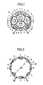
- Fig. 1 is a front view of an embodiment of a speaker body used in the speaker system of the present invention.
- Fig. 2 is a sectional view of the speaker body shown in Fig. 1.
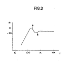
- Fig. 3 is a graphical representation showing an example of a peak and a dip in frequency response with respect to a speaker unit used in the speaker system of the present invention.
- Fig. 4 is a block diagram of an embodiment of the speaker system of the present invention.
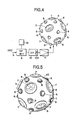
- Fig. 5 is a perspective view showing an example of arrangement of speaker units in another embodiment of the speaker body used in the speaker system of the present invention.
- Fig. 6 is a block diagram of one form of a plane baffle type speaker system using a digital equalizer.
- Fig. 7 is a block diagram of one form of a speaker system using the speaker systems in Fig. 6 in parallel.
- the speaker enclosure is preferably a hollow about 32- or more-hedron or a hollow sphere so as to provide a person with substantially the same auditory feeling as that caused by spherical wave due to a respiratory sphere.
- positional relationship between a woofer designed to handle a low range and a tweeter designed to handle a mid-high range and optimum location of the arrangement incorporating the positional relationship are experimentally determined using a 32-hedron (which is the polyhedron having minimum surfaces among the above- described preferred polyhedrons) from a practical viewpoint to realize the speaker system of the present invention.
- a 32-hedron which is the polyhedron having minimum surfaces among the above- described preferred polyhedrons
- the enclosure is preferably placed in such a manner that the top and bottom surfaces thereof are pentagonal surfaces. The same applies to the case where a sphere whose surface are supposed to be composed of pentagonal surfaces and hexagonal surfaces is used as an enclosure.
- a hollow 32 -hedron whose external surface is composed of 12 pentagonal surfaces 1 and 20 hexagonal surfaces 2 is the basic structure of an enclosure EC (which is also referred to as a speaker cabinet or speaker box).
- All of the 12 pentagonal surfaces 1 or, from practical viewpoint, 9 to 11 of the 12 pentagonal surfaces 1 are each provided with a speaker unit for a low range (woofer) 7, and all of the 20 hexagonal surfaces 2 or, from practical viewpoint, 15 to 19 of the 20 hexagonal surfaces 2 are each provided with a speaker unit for a mid- high range (tweeter) 8 to form a speaker body.
- a speaker unit for a low range (woofer) 7 All of the 20 hexagonal surfaces 2 or, from practical viewpoint, 15 to 19 of the 20 hexagonal surfaces 2 are each provided with a speaker unit for a mid- high range (tweeter) 8 to form a speaker body.
- a peak 4 and a dip 5 are caused in frequency response as diagrammatically shown in Fig. 3.
- driving signals of the speaker units 7 and 8 are subjected to reverse characteristic filtering by means of a digital signal processor 6 (hereinafter referred to as DSP 6) as shown in Fig. 4.
- DSP 6 digital signal processor 6
- reference numeral 9 represents a digital input signal inputted to the DSP 6, reference numeral 10 a D/A converter block, reference numeral 11 a power amplifier, reference numeral 12 a controlling panel connected to the DSP 6, and reference numeral 100 an analog attenuator inserted in advance of the power amplifier 11.
- a program of a finite impulse response filter (FIR filter) or a program of a combination filter of an FIR filter with an Infinite impulse response filter (IIR filter) is preliminarily loaded into a program memory of the DSP 6 for processing digital input signals which is shown in Fig. 4, and coefficient of inverse correction of speaker responses including distortion of frequency & phase response inherent in each of the speaker units is preliminarily loaded into a coefficient memory.
- FIR filter finite impulse response filter
- IIR filter Infinite impulse response filter
- the input signals 9 are subjected to processing for inverse correction of frequency response and phase response of the speaker units of the present invention by means of a real time digital signal processing system of the DSP 6, and the digital signals are converted into analog signals by means of the D/A converter 10.
- the controlling panel 12 of the DSP 6 forming the real time digital signal processing system is provided with a controlling unit capable of changing output sound volume of each of the speaker units 7 and 8 or speaker units 78.
- the analog attenuator 100 is controlled by the controlling unit to determine volume of reproduced sound, and a value corresponding to the determined sound volume is allotted to elements of user bit in subcode of AES/EBU, SPDIF or the like which is a serial transmission format for digital audio signals or elements of bit which is not required by the D/A converter in subcode to multiplex control data for controlling sound volume into signals for driving a speaker.
- the signals for driving a speaker are transferred to the D/A converter block 10.
- a signal line 21 for analog attenuators 14 which is used to control sound volume in the conventional speaker system shown in Fig. 7 can be eliminated. Accordingly, disadvantage is not caused which is due to contact failure of the control line for the attenuators 14 or the like. Further, signal processing by the DSP 6 and sound volume control can be performed using the same controlling panel 12. This enables sound volume to be determined arbitrarily as well as the DSP 6 to be operated at the optimum signal level to constantly maintain arithmetic accuracy at the highest condition. Therefore, no lowering of S/N ratio nor undesirably high distortion degree is caused in reproduced sound. This is because volume information is read out from a subcode in the D/A converter block 10 and converted into an analog audio signal by the D/A converter 10, and level of the audio signal is controlled by the analog attenuator 100.
- Figs. 1 and 2 show an embodiment of a speaker body in the speaker system of the present invention, which comprises an enclosure EC in the form of a hollow 32 - hedral frame having stiffness and speaker units for a low range 7 and speaker units for a mid-high range 8 disposed in the hollow frame substantially equidistantly at a distance "a" from the center O of the hollow frame.
- Each of the speaker units 7 and 8 of this system is driven by a power amplifier 11 shown in Fig. 4.
- analog signals to be inputted to the power amplifier 11 are obtained by filtering input signals in real time by means of digital signal processing in a DSP 6 to correct characteristics of the speaker units 7 and 8, and converting the resulting digital output signals into analog signals by a D/A converter 10.
- the analog signals are amplified by the power amplifier 11 to drive speaker units 7 and 8.
- Fig. 5 shows another embodiment of a speaker body of the speaker system of the present invention, which comprises an enclosure EC in the form of a hollow spherical frame having stiffness and 12 woofers 7 and 20 tweeters 8, and which is constructed by suppositionally dividing the outer surface of the spherical frame into 12 pentagonal portions and 20 hexagonal portions and disposing a woofer 7 and a tweeter 8 in each of the pentagonal portions and in each of the hexagonal portions, respectively.
- an enclosure EC in the form of a hollow spherical frame having stiffness and 12 woofers 7 and 20 tweeters 8, and which is constructed by suppositionally dividing the outer surface of the spherical frame into 12 pentagonal portions and 20 hexagonal portions and disposing a woofer 7 and a tweeter 8 in each of the pentagonal portions and in each of the hexagonal portions, respectively.
- a peak 4 and a dip 5 are caused in frequency response, as in the two preceding embodiments, when the speaker body as such is driven.
- a real time digital signal processing system which comprises a DSP 6 as main means is inserted in advance of a power amplifier 11.
- a program of an FIR filter or a program of a combination filter of an FIR filter with an IIR filter is preliminarily loaded into a program memory of the DSP 6, and coefficient of inverse correction of speaker responses including distortion of frequency & phase response inherent in each of the speaker units 7 and 8 is preliminarily loaded into a coefficient memory.
- the input signals 9 are subjected to processing for inverse correction of frequency response and phase response by means of the real time digital signal processing system comprising the DSP 6 as main means, and the treated digital signals are converted into analog signals by means of the D/A converter 10.
- the analog signals are amplified by the power amplifier 11 to drive the speaker system of the present invention.
- -8 decibel(dB) and +10 (dB) are set as correction of the peak 4 and correction of the dip 5 of the frequency response in the DSP 6, respectively.
- the values change depending upon size (volume) of the enclosure EC, types of the speaker units 7, 8 (for example, a conical type, a dome type, etc.), and other factors.
- the driving signals for the speaker units 8 as tweeters are delayed by about 60 microseconds ( ⁇ sec.) as compared with the driving signals for the speaker units 7 as woofers, taking it into consideration that the distance from the center O of the hollow 32-hedron to a diaphragm of each speaker unit 7 as a woofer is somewhat different from the distance from the center O to a diaphragm of each speaker unit 8 as a tweeter.
- Analog signals to be inputted to the power amplifier 11 are obtained by filtering input signals in real time by means of digital signal processing in the DSP 6 to correct characteristics of the speakers 7 and 8, and converting the resulting digital output signals into analog signals by the D/A converter 10.
- each of legs for placing the speaker body or a hook (or eye) for suspending the speaker body is located at a vacant portion of the enclosure EC, on which no speaker unit is disposed or a portion on which a speaker unit is not disposed intendedly for this purpose.
- an input cable for each speaker unit may be introduced in the same manner as above.
- a high fidelity speaker system for professional consumers, a loud speaker for a public address system or the like, or a speaker system used as a point sound source for measuring acoustic characteristics of a hall, i. e., a converter which converts electric signals into acoustic signals is required to have its sound emitting point at the center of a sphere or sphere-like polyhedron and to be capable of transmitting substantially uniform vibrational energy to the surrounding space all around.
- the speaker system of the present invention has such a structure that speaker units are disposed in the surfaces of an enclosure in the form of a hollow sphere or sphere-like polyhedron such as 32 -hedron, which surfaces are located equidistantly from the center of the enclosure.
- the speaker system of the present invention is capable of emitting. substantially uniform vibrational energy and transmitting the vibrational energy to the surrounding space all around.
- the speaker system of the present invention is constructed as a multiway loudspeaker system which comprises (a) speaker units allotted to each of more than two specific sound ranges speaker units, input signals for each of the sound ranges are subjected to digital signal processing to correct frequency response. It is thereby possible to attain a wave front generated by sounds emitted from the speaker units, which is uniform and equidistant from the center of a sphere or sphere-like polyhedron such as 32- hedron. Therefore, if constructed as a multiway loudspeaker system, the speaker system of the present invention is capable of emitting substantially uniform vibrational energy to the surrounding space all around.
- DSP digital signal processor
- the enclosure to which the speaker units are mounted has a spherical or sphere- like polygonal structure having a curved surface or polyhedrally continuous surface. It is thereby possible to considerably suppress concomitant sound due to vibration of a hexahedral box (enclosure), which is likely to be caused in a conventional system comprising a hexahedral enclosure composed of flat surfaces to which speaker units are mounted.
- the speaker units are well-balancedly distributed over the entire outer surface of the sphere or polyhedron in such a manner that a plurality of the speaker units for a high range are arranged around the speaker units for a low to mid-range whose sounds are easily diffused. Consequently, reproduced sounds in the full range are substantially uniformly diffused all around the enclosure, thereby greatly contributing to realization of non-directional reproduced sounds emitted from a point sound source in cooperation with the above- mentioned function.
- the present invention is as described above. It is, therefore, possible to provide a non-directional speaker system having a point sound source, which exhibits good localization of acoustic image and excellent reproducibility of propagation of a sound field. Accordingly, the speaker system of the present invention is extremely useful as a so-called high fidelity speaker system for professional or commercial use, a loud speaker for a public address system or the like, or a point sound source for measuring acoustic characteristics of a hall.
Description
- The present invention relates to a non-directional speaker system with a point sound source which is capable of emitting a spherical sound wave whose focal point is clear to the surrounding space all around the speaker system. It relates to a speaker system which is capable of stereophonically reproducing presence of each sound emitter such as a person's voice or a musical instrument which is included in a sound source.
- When a tuning fork is struck to vibrate, vibration of air whose sound emission source is the tuning fork spherically propagates over the surrounding space around the tuning fork. In other words, because the sound emitted from the tuning fork is heard at substantially the same sound pressure at any spatial positions equidistant from the tuning fork irrespective of directions, the sound wave emitted from the struck tuning fork is recognized to propagate as a spherical wave. When the sound of the tuning fork is collected and recorded through a microphone and reproduced by a conventional speaker system comprising a hexahedron (rectangular parallelepipedic enclosure) and a speaker unit disposed on one of the surfaces of the hexahedral enclosure, sound pressure level is high only in the front of the speaker unit but low outside the front. Accordingly, the spherical wave from the tuning fork cannot be reproduced.
- Heretofore, speaker systems have been used in reproduction of a music, amplification of a speech, reproduction of natural sounds and sound effects in a movie, and the like. However, many of sound emitters included in the sound source reproduced through a speaker unit, for example, percussion instruments and wood winds are non- directional and emit a spherical wave. Further, although stringed instruments have a sound emitting portion on one side thereof, they are roughly regarded as substantially non- directional sound emitters because of sound box-induced resonance acting as an influential tonal quality factor. Therefore, the majority of sound emitters may be considered to emit a non-directional spherical wave.
- On the other hand, it is considered that human's sense of hearing detects direction of a sound source through direct sounds coming from a musical instrument in the shortest course, and in parallel, compares information on indirect sounds from surrounding reflective objects such as a floor, a wall and a ceiling with experiential values, thereby realizing distance to the musical instrument, i. e., sound source, reality of the musical instrument, and vividness.
- Some of brass instruments such as a trumpet have their tones extremely different between the front and the rear thereof, that is, they are highly directional. In such highly directional instruments, frontal tones correspond generally to the sounds intrinsic to the instruments. This is similar to sound emitting mode of a nomodirectional speaker system. Accordingly, it tends to be considered that a non- directional speaker system with a point sound source is not suitable for reproducing sounds of brass instruments. However, with respect to sounds reproduced by a speaker system, in the absence of appearance of a player, a person who hears the reproduced sounds needs information on the sense of distance through indirect sounds so as to recognize existence of a musical instrument such as a trumpet or presence of sounds emitted therefrom. To reproduce with high fidelity any sounds from the above sound emitters, i. e., sound emitters which emit sounds in various mode, use of a non-directional spherical wave speaker system with a point sound source is preferred which is capable of exhibiting excellent characteristics in reproduction of sounds of unidirectional and highly directional musical instruments. The reasons for this are as follows.
- (a) In a unidirectional speaker system of the most ordinary type, which comprises a hexahedral enclosure and a speaker unit mounted to one of the surfaces of the enclosure, right sounds of musical instruments are emitted only in the direction of the front of the speaker system, and other sounds corresponding to indirect sounds of the sound source are emitted in other directions than the front direction. If follows then that two different musical instruments respectively emitting the direct sounds and the indirect sounds are virtually existent at the position of the sound emitter. This causes a delicate gap between acoustic images, and as a result, prevents person's sense of hearing from forming an acoustic image with reality.
- (b) In view of this problem, speaker systems have been proposed in, for recent example, Japanese Patent Unexamined Publication No. 205490/1994 which comprise a polyhedral or spherical enclosure and speaker units uniformly mounted on the surface(s) of the enclosure, and some of them have been practically used. Further, a report on "non-directional speaker" has been published in "JAS JOURNAL, September, 1993". In Patent Abstracts of Japan, Vol. 95, No. 6, 31.07.95 & Derwent Abstracts AN 95-166114 & JP-A-7087585, 31.03.1995, a frame of a 32-hedron or sphere is shown, with speaker units being mounted in the surfaces of the frame.In U.S. Patent US-A-4673057 to J.M. Glassco, an arrangement of a plurality of similar speakers mounted in an air tight frame is shown. Especially, in Fig. 6 of said document, a 32-hedron is shown, with speakers being mounted in the surfaces of this frame. Additionally, ways for suspending the whole speaker arrangements are given.In German patent application DE-A-31 42 462 to H.-P. Pfeiffer, an arrangement of speakers is disclosed including a speaker whose direction of sound emission has at least one vertical component. The sound emitted from said speaker is reflected by the walls and the ceiling of a listening room and contributes to a more vivid acoustic impression. A microprocessor unit provides time delays in order to compensate phase shifts between different speaker units. However, with respect to such a conventional spherical wave emitting type speaker system comprising a polyhedron or sphere and speaker units mounted thereon, it has been known that a peak and a dip are observed in frequency response. Such a conventional speaker system has a drawback that it cannot be driven as a high fidelity speaker system unless the peak and the dip are corrected.
- (c) On the other hand, it has been known in conventional analog technique that when the defect in frequency response is corrected, phase distortion is con-comitanly caused. There have been experimental reports on correction effected by means of an analog equalizer with a view to elucidating relationship between the phase distortion and auditory feeling. As an example of those reports, there may be mentioned "Phase and tonal quality" reported in "pre-lecture publication for AES Tokyo Convention, 1995". It is, however, difficult to effect correction by analog treatment at strict sound pressure level. Further, phase response is affected by correction of frequency response. Accordingly, is has been said that a clear acoustic image cannot be obtained by a conventional non-directional speaker system using analog technique.
- (d) Further, a speaker system which generates a quasi-spherical wave using a round reflector has hereto fore been proposed as one type of non-directional speaker systems. In the speaker system, however, frequency response and phase response are affected due to the reflector. In spite of the fact that cancel treatment is required to cope with the undesired influence, the speaker system is not constructed taking this point into consideration. Accordingly, reproduction of a point sound emitter, which is a basic performance of a non-directional speaker system, is not realized.
- (e) Recently, it has been attempted to evenly correct frequency response and phase response of a speaker system using a hexahedral enclosure by real time digital signal processing by means of a digital signal processor. However, this attempt has been made with a view only to applying digital signal processing to a multiway speaker unit mounted to a conventional hexahedral enclosure. Accordingly, the attempt is not development of a speaker system which, per se, is capable of realizing a non-directional spherical sound wave with a point sound source which is sound emission mechanism of a natural sound. In U.S. Patent US-A-5384856 to N. Kyouno, Y. Osuga, N. Yashima, means for setting a desired transmission frequency response are disclosed. In order to flatten the amplitude characteristic of an overall transmission frequency response of each channel and to obtain a linear phase frequency response, a time series impulse response is calculated based on an inverse characteristic and this time series impulse response is made to be a filter factor. This filter factor and the digital input signal are calculated by convolution operations.In European patent application EP-A-0 567 061 a method and system for reproducing audio frequencies is given. The frequency response of the loudspeaker is equalized with a filter. Prior to feeding a signal into a wide band one-way loudspeaker reproducing frequencies substantially over the entire audio range, the frequency response of the loudspeaker mounted to its cabinet is equalized with a filter, which is a wide band filter also covering substantially the entire audio range. With the filter an approximate inverse response is implemented in the desired pass band of the loudspeaker system, the inverse response being formed according to a frequency response of said loudspeaker system, which is a measured frequency response of said loudspeaker system.
- (f) Such a real time digital signal processing unit using a digital signal processor as mentioned above has been commercially available as a digital equalizer which is unitary. When a speaker system with a digital equalizer is constructed using such a digital equalizer, it is as shown in the block diagram in Fig. 6. When the speaker system in Fig. 6 is used in, for example, a public address system or the like, the following problems are caused.
-
- Generally, in public address system, an
analog attenuator 13 is provided in a monitor output portion of a mixing console which is operated by a mixing engineer, and sound volume is controlled by operating theattenuator 13. When the speaker system in Fig. 6 is used in a high fidelity audio system, theattenuator 13 is provided in a control amplifier which is operated by a listener, and sound volume is controlled by operating the attenuator as described above. - On the other hand, in the speaker system in Fig. 6, an
analog attenuator 14 inserted in advance of apower amplifier 17 is usually preset for presetting input gain of thepower amplifier 17. Accordingly, if theanalog attenuator 14 is set so as not to cause distortion of output sounds of aspeaker unit 18 at the maximum power, in usual conditions operated at lower volume levels, sound volume is controlled by theanalog attenuator 13 located at the upper stream of the input system. This leads to a low level of signals inputted to an A/D converter 15, thereby preventing the A/D converter 15 from performing highly precise analog- digital conversion. As a result, low levels of input signals are processed by adigital equalizer 16, and computing errors are accumulated in the course of signal processing. Consequently, there is a problem in that disadvantages such as increase of noise and aggravation of distortion ratio are caused. - To solve the above- mentioned problem, a speaker system has been proposed and practically used which comprises a
master attenuator 20 placed within reach of a mixing engineer and aspecial signal line 21 for level controlling signals besides a sound signal line to control theanalog attenuator 14. When this system is applied to, for example, a system using a number of speaker units in parallel, such as a public address system, the resulting system has a construction as shown in the block diagram in Fig. 7. However, in such a large- sized speaker system, for example, an incident is likely to be caused that even if reduction of sound volume is required at the end of a tune, sound volume is out of control in only one channel and the sound volume of thespeaker unit 18 of the channel cannot be reduced due to a cause such as contact failure of a connector. - As described above, in terms of sound emission mechanism of sound emitters, such as musical instruments and natural sound emitters, whose sounds are to be reproduced by a speaker system, there are many non- directional sound emitters, and listener's sense of hearing recognizes existence of a sound emitter more clearly by indirect sounds. In view of these facts, a non- directional speaker system with a point sound source is considered to be an ideal sound emitter for reproducing sounds emitted by a sound emitter with high fidelity.
- Further, conception of "respiratory sphere" has heretofore been known. If sounds can be reproduced by a speaker system in such a manner that entire surface of a sphere is uniformly expanded and contracted to transmit vibrations of sound wave to air, it is possible to listen reproduced sounds in the same mode as sound emission mechanism of musical instruments or natural sound emitter, i. e., in such a mode that sound at the same sound pressure can be heard at positions equidistant from the speaker system. However, a non- directional speaker system with a point sound source has not been provided which is capable of reproducing sounds in a wide range of about 20Hz to about 20KHz in the same manner as that of the respiratory sphere.
- It is, therefore, an object of the present invention to provide a speaker system which is capable of supplying reproduced sounds vibrating in substantially the same manner as in the respiratory sphere to human's sense of hearing by using conventional unidirectional speaker units in combination in a contrived arrangement, and by applying real time digital signal processing by means of a digital signal processor to the speaker units to cancel a peak and a dip in frequency response and in phase response through inverse correction which cannot be canceled only by improving the arrangement of the speaker units, thereby forming a sound emitter capable of providing ideal reproduced sounds. It is another object of the present invention to effect real time digital signal processing in optimum conditions without additionally providing a special signal line for controlling signals of the attenuator, by inserting an analog level controller practically required such as an analog attenuator downstream from a D/A converter in an input signal line.
- The present invention has been made with a view to solving the above- mentioned problems.
- According to the present invention, there is provided a non- directional speaker system with a point sound source comprising:
- an enclosure having a basic structure of a hollow 32-hedron composed of 12 pentagonal flat surfaces and 20 hexagonal flat surfaces,
- woofers (speaker units for a low range) respectively mounted in 9-12 of the pentagonal surfaces and tweeters (speaker units for a high range) respectively mounted in 15-20 of the hexagonal surfaces, and
- a real time digital signal processing system inserted in a input line of each of the speaker units, the real time digital signal processing system inverse-characteristically filtering driving signals of the speaker units to evenly correcting a peak and a dip caused in frequency response and in phase response of each of the speaker units.
-
- In the above speaker system of the present invention, the enclosure has a basic structure of a hollow 32- hedron composed of 12 pentagonal flat surfaces and 20 hexagonal flat surfaces, and a speaker unit for a low range or low-mid range is mounted in each of 9-12 pentagonal surfaces and a speaker unit for a mid- high range or high range is mounted in each of 15-20 hexagonal surfaces. The speaker units are thereby mounted to the sphere or polyhedron or sphere in such a well-balanced arrangement that a plurality of the speaker units for a mid-high range or high range are disposed around each of the speaker units for a low range or low-mid range. Accordingly, it is possible to provide a further widened range of reproduced sounds all around the speaker body.
- Further, in the above speaker system of the present invention, controlling data for sound volume control are multiplexed into SPDIF or AES/EBU signals which are digital audio interface standard signals and transmitted to a D/A converter blocks and level of analog signals resulting from D/A conversion is controlled, thereby always maintaining arithmetic accuracy of the real time digital signal processing system at the best condition. Accordingly, arithmetic accuracy of the real time digital signal processing system can be maintained at the best condition, and sounds are reproduced from the speaker systems without any distortion of information on sound emitters.
- Fig. 1 is a front view of an embodiment of a speaker body used in the speaker system of the present invention.
- Fig. 2 is a sectional view of the speaker body shown in Fig. 1.
- Fig. 3 is a graphical representation showing an example of a peak and a dip in frequency response with respect to a speaker unit used in the speaker system of the present invention.
- Fig. 4 is a block diagram of an embodiment of the speaker system of the present invention.
- Fig. 5 is a perspective view showing an example of arrangement of speaker units in another embodiment of the speaker body used in the speaker system of the present invention.
- Fig. 6 is a block diagram of one form of a plane baffle type speaker system using a digital equalizer.
- Fig. 7 is a block diagram of one form of a speaker system using the speaker systems in Fig. 6 in parallel.
- Now, embodiments of the present invention will be described.
- As a well- balanced polyhedron preferably used in the speaker system of the present invention, there may be mentioned regular dodecahedron, regular icosahedron, 32-hedron composed of pentagonal surfaces and hexagonal surfaces, 180-hedron and the like. In the present invention, however, the speaker enclosure is preferably a hollow about 32- or more-hedron or a hollow sphere so as to provide a person with substantially the same auditory feeling as that caused by spherical wave due to a respiratory sphere. In the speaker system of the present invention, positional relationship between a woofer designed to handle a low range and a tweeter designed to handle a mid-high range and optimum location of the arrangement incorporating the positional relationship are experimentally determined using a 32-hedron (which is the polyhedron having minimum surfaces among the above- described preferred polyhedrons) from a practical viewpoint to realize the speaker system of the present invention. In terms of a sound receiving point, in the speaker system of the present invention which uses a hollow 32- hedron as an enclosure, the enclosure is preferably placed in such a manner that the top and bottom surfaces thereof are pentagonal surfaces. The same applies to the case where a sphere whose surface are supposed to be composed of pentagonal surfaces and hexagonal surfaces is used as an enclosure.
- In the next place, mode for operation of the speaker system of the present invention will be described with reference to the accompanying drawings. In the speaker system of the present invention illustrated in Figs. 1 and 2, a hollow 32 -hedron whose external surface is composed of 12
pentagonal surfaces hexagonal surfaces 2 is the basic structure of an enclosure EC (which is also referred to as a speaker cabinet or speaker box). All of the 12pentagonal surfaces 1 or, from practical viewpoint, 9 to 11 of the 12pentagonal surfaces 1 are each provided with a speaker unit for a low range (woofer) 7, and all of the 20hexagonal surfaces 2 or, from practical viewpoint, 15 to 19 of the 20hexagonal surfaces 2 are each provided with a speaker unit for a mid- high range (tweeter) 8 to form a speaker body. - If the speaker body as such, which comprises a 32-hedron provided with
speaker units peak 4 and a dip 5 are caused in frequency response as diagrammatically shown in Fig. 3. In the present invention, however, to correct the distortion appearing as thepeak 4 and dip 5 to substantially even the frequency response, driving signals of thespeaker units reference numeral 9 represents a digital input signal inputted to theDSP 6, reference numeral 10 a D/A converter block, reference numeral 11 a power amplifier, reference numeral 12 a controlling panel connected to theDSP 6, and reference numeral 100 an analog attenuator inserted in advance of thepower amplifier 11. - In the speaker system of the present invention, when each of the
speaker units DSP 6 for processing digital input signals which is shown in Fig. 4, and coefficient of inverse correction of speaker responses including distortion of frequency & phase response inherent in each of the speaker units is preliminarily loaded into a coefficient memory. - As shown in the block diagram in Fig. 4, the input signals 9 are subjected to processing for inverse correction of frequency response and phase response of the speaker units of the present invention by means of a real time digital signal processing system of the
DSP 6, and the digital signals are converted into analog signals by means of the D/A converter 10. - In the present invention, the controlling
panel 12 of theDSP 6 forming the real time digital signal processing system is provided with a controlling unit capable of changing output sound volume of each of thespeaker units analog attenuator 100 is controlled by the controlling unit to determine volume of reproduced sound, and a value corresponding to the determined sound volume is allotted to elements of user bit in subcode of AES/EBU, SPDIF or the like which is a serial transmission format for digital audio signals or elements of bit which is not required by the D/A converter in subcode to multiplex control data for controlling sound volume into signals for driving a speaker. The signals for driving a speaker are transferred to the D/A converter block 10. - By virtue of this constitution, a
signal line 21 foranalog attenuators 14 which is used to control sound volume in the conventional speaker system shown in Fig. 7 can be eliminated. Accordingly, disadvantage is not caused which is due to contact failure of the control line for theattenuators 14 or the like. Further, signal processing by theDSP 6 and sound volume control can be performed using the same controllingpanel 12. This enables sound volume to be determined arbitrarily as well as theDSP 6 to be operated at the optimum signal level to constantly maintain arithmetic accuracy at the highest condition. Therefore, no lowering of S/N ratio nor undesirably high distortion degree is caused in reproduced sound. This is because volume information is read out from a subcode in the D/A converter block 10 and converted into an analog audio signal by the D/A converter 10, and level of the audio signal is controlled by theanalog attenuator 100. - Figs. 1 and 2 show an embodiment of a speaker body in the speaker system of the present invention, which comprises an enclosure EC in the form of a hollow 32 - hedral frame having stiffness and speaker units for a
low range 7 and speaker units for amid-high range 8 disposed in the hollow frame substantially equidistantly at a distance "a" from the center O of the hollow frame. Each of thespeaker units power amplifier 11 shown in Fig. 4. - Referring to Fig. 4, analog signals to be inputted to the
power amplifier 11 are obtained by filtering input signals in real time by means of digital signal processing in aDSP 6 to correct characteristics of thespeaker units A converter 10. The analog signals are amplified by thepower amplifier 11 to drivespeaker units - Fig. 5 shows another embodiment of a speaker body of the speaker system of the present invention, which comprises an enclosure EC in the form of a hollow spherical frame having stiffness and 12
woofers tweeters 8, and which is constructed by suppositionally dividing the outer surface of the spherical frame into 12 pentagonal portions and 20 hexagonal portions and disposing awoofer 7 and atweeter 8 in each of the pentagonal portions and in each of the hexagonal portions, respectively. - Also in the speaker body of the speaker system of the present invention comprising the hollow 32-hedral or spherical enclosure and the
woofers 7 andtweeters 8 which are disposed on the enclosure in such an arrangement, apeak 4 and a dip 5 are caused in frequency response, as in the two preceding embodiments, when the speaker body as such is driven. To substantially even thepeak 4 and dip 5 and poorness in a low frequency range, a real time digital signal processing system which comprises aDSP 6 as main means is inserted in advance of apower amplifier 11. - In the present invention, to subject analog or digital input signals to digital signal processing, a program of an FIR filter or a program of a combination filter of an FIR filter with an IIR filter is preliminarily loaded into a program memory of the
DSP 6, and coefficient of inverse correction of speaker responses including distortion of frequency & phase response inherent in each of thespeaker units - By virtue of this, the input signals 9 are subjected to processing for inverse correction of frequency response and phase response by means of the real time digital signal processing system comprising the
DSP 6 as main means, and the treated digital signals are converted into analog signals by means of the D/A converter 10. The analog signals are amplified by thepower amplifier 11 to drive the speaker system of the present invention. - In the above embodiments, -8 decibel(dB) and +10 (dB) are set as correction of the
peak 4 and correction of the dip 5 of the frequency response in theDSP 6, respectively. In this connection, the values change depending upon size (volume) of the enclosure EC, types of thespeaker units 7, 8 (for example, a conical type, a dome type, etc.), and other factors. Further, in the third embodiment, the driving signals for thespeaker units 8 as tweeters are delayed by about 60 microseconds (µ sec.) as compared with the driving signals for thespeaker units 7 as woofers, taking it into consideration that the distance from the center O of the hollow 32-hedron to a diaphragm of eachspeaker unit 7 as a woofer is somewhat different from the distance from the center O to a diaphragm of eachspeaker unit 8 as a tweeter. Analog signals to be inputted to thepower amplifier 11 are obtained by filtering input signals in real time by means of digital signal processing in theDSP 6 to correct characteristics of thespeakers A converter 10. - In each of the embodiments of the present invention shown in Figs. 1, 2 and 5, each of legs for placing the speaker body or a hook (or eye) for suspending the speaker body is located at a vacant portion of the enclosure EC, on which no speaker unit is disposed or a portion on which a speaker unit is not disposed intendedly for this purpose. Further, an input cable for each speaker unit may be introduced in the same manner as above.
- Ideally, a high fidelity speaker system for professional consumers, a loud speaker for a public address system or the like, or a speaker system used as a point sound source for measuring acoustic characteristics of a hall, i. e., a converter which converts electric signals into acoustic signals is required to have its sound emitting point at the center of a sphere or sphere-like polyhedron and to be capable of transmitting substantially uniform vibrational energy to the surrounding space all around.
- Heretofore, as one capable of exhibiting the above- mentioned performance, a wide- directional speaker system having a 12-hedral enclosure or the like has been provided. However, it has seldom been used in reproducing a music. The reason for this resides in that it is greatly different from the above-mentioned ideal shape because of the small number of its sound emitting surfaces. On the other hand, however, if a hollow sphere or sphere- like hedron is used as a speaker enclosure, correction of so- called "turbulence" of frequency response which is inherent in such an enclosure cannot be effected precisely and appropriately.
- As opposed to the above conventional technique, the speaker system of the present invention has such a structure that speaker units are disposed in the surfaces of an enclosure in the form of a hollow sphere or sphere-like polyhedron such as 32 -hedron, which surfaces are located equidistantly from the center of the enclosure. By virtue of this, the speaker system of the present invention is capable of emitting. substantially uniform vibrational energy and transmitting the vibrational energy to the surrounding space all around.
- Further, if the speaker system of the present invention is constructed as a multiway loudspeaker system which comprises (a) speaker units allotted to each of more than two specific sound ranges speaker units, input signals for each of the sound ranges are subjected to digital signal processing to correct frequency response. It is thereby possible to attain a wave front generated by sounds emitted from the speaker units, which is uniform and equidistant from the center of a sphere or sphere-like polyhedron such as 32- hedron. Therefore, if constructed as a multiway loudspeaker system, the speaker system of the present invention is capable of emitting substantially uniform vibrational energy to the surrounding space all around.
- Moreover, in the speaker system of the present invention, its digital signal processor (DSP) corrects decrease in a low range of frequency response, suppresses increase of frequency response at the frequency point from which the decrease is observed to the lower range, and corrects dip appearing in the higher range. Consequently, it is possible to effectively cancel phase distortion due to differences in distances from the center of the sphere to the speaker units and due to differences in response times of diaphragms of the speaker units.
- Furthermore, in the present invention, the enclosure to which the speaker units are mounted has a spherical or sphere- like polygonal structure having a curved surface or polyhedrally continuous surface. It is thereby possible to considerably suppress concomitant sound due to vibration of a hexahedral box (enclosure), which is likely to be caused in a conventional system comprising a hexahedral enclosure composed of flat surfaces to which speaker units are mounted. Further, in the present invention, the speaker units are well-balancedly distributed over the entire outer surface of the sphere or polyhedron in such a manner that a plurality of the speaker units for a high range are arranged around the speaker units for a low to mid-range whose sounds are easily diffused. Consequently, reproduced sounds in the full range are substantially uniformly diffused all around the enclosure, thereby greatly contributing to realization of non-directional reproduced sounds emitted from a point sound source in cooperation with the above- mentioned function.
- The present invention is as described above. It is, therefore, possible to provide a non-directional speaker system having a point sound source, which exhibits good localization of acoustic image and excellent reproducibility of propagation of a sound field. Accordingly, the speaker system of the present invention is extremely useful as a so-called high fidelity speaker system for professional or commercial use, a loud speaker for a public address system or the like, or a point sound source for measuring acoustic characteristics of a hall.
Claims (6)
- A non-directional speaker system with a point sound source comprising:an enclosure having a basic structure of a hollow 32-hedron composed of 12 pentagonal flat surfaces (1) and 20 hexagonal flat surfaces (2),woofers speaker units for a low range, (7) respectively mounted in 9-12 of the pentagonal surfaces (1) and tweeters speaker units for a high range, (8) respectively mounted in 15-20 of the hexagonal surfaces (2), anda real time digital signal processing system (6) inserted in an input line (9) of each of the speaker units, the real time digital signal processing system (6) inverse-characteristically filtering driving signals of the speaker units to evenly correcting a peak (4) and a dip (5) caused in frequency response and in phase response of each of the speaker units.
- The non-directional speaker system with a point sound source according to claim 1, wherein the speaker units mounted in the outer surface of the sphere-like polyhedron are such that speaker units for a mid-high range or high range (8) are disposed around each of speaker units for a low range or low-mid range (7).
- The non-directional speaker system with a point sound source according to any one of claims 1 or 2, wherein controlling data for sound volume control are multiplexed into SPDIF or AES/EBU signals which are digital audio interface standard signals and transmitted to a D/A converter block (10), and level of analog signals resulting from D/A conversion is controlled, thereby always maintaining arithmetic accuracy of the real time digital signal processing system at the best condition.
- A non-directional speaker system with a point sound source comprising:an enclosure having a basic structure of a sphere whose outer surface is suppositionally divided like a 32-hedron into 32 surfaces composed of 12 pentagonal surfaces and 20 hexagonal surfaces.woofers speaker units for a low range, respectively mounted in 9-12 of the pentagonal surfaces and tweeters, speaker units for a high range, respectively mounted in 15-20 of the hexagonal surfaces, anda real time digital signal processing system inserted in an input line of each of the speaker units, the real time digital signal processing system inverse-characteristically filtering driving signals of the speaker units to evenly correcting a peak and a dip caused in frequency response and in phase response of each of the speaker units.
- The non-directional speaker system with a point sound source according to claim 4, wherein the speaker units mounted in the outer surface of the sphere are such that speaker units for a mid-high range or high range (8) are disposed around each of speaker units for a low range or low-mid range (7).
- The non-directional speaker system with a point sound source according to any one of claims 4 or 5, wherein controlling data for sound volume control are multiplexed into SPDIF or AES/EBU signals which are digital audio interface standard signals and transmitted to a D/A converter block (10), and level of analog signals resulting from D/A conversion is controlled, thereby always maintaining arithmetic accuracy of the real time digital signal processing system at the best condition.
Applications Claiming Priority (4)
| Application Number | Priority Date | Filing Date | Title |
|---|---|---|---|
| JP248587/95 | 1995-09-01 | ||
| JP7248587A JPH0970092A (en) | 1995-09-01 | 1995-09-01 | Point sound source, non-oriented speaker system |
| JP24858795 | 1995-09-01 | ||
| US08/610,999 US5812685A (en) | 1995-09-01 | 1996-03-07 | Non-directional speaker system with point sound source |
Publications (3)
| Publication Number | Publication Date |
|---|---|
| EP0762801A2 EP0762801A2 (en) | 1997-03-12 |
| EP0762801A3 EP0762801A3 (en) | 1998-05-20 |
| EP0762801B1 true EP0762801B1 (en) | 2001-06-27 |
Family
ID=26538846
Family Applications (1)
| Application Number | Title | Priority Date | Filing Date |
|---|---|---|---|
| EP96113944A Expired - Lifetime EP0762801B1 (en) | 1995-09-01 | 1996-08-30 | Non-directional speaker system with point sound source |
Country Status (3)
| Country | Link |
|---|---|
| US (1) | US5812685A (en) |
| EP (1) | EP0762801B1 (en) |
| JP (1) | JPH0970092A (en) |
Cited By (3)
| Publication number | Priority date | Publication date | Assignee | Title |
|---|---|---|---|---|
| CN107113494A (en) * | 2014-08-18 | 2017-08-29 | 苹果公司 | Rotationally symmetrical loudspeaker array |
| CN107615781A (en) * | 2015-05-14 | 2018-01-19 | 尤金尼·博古斯拉夫斯基 | Loudspeaker |
| CN111405418A (en) * | 2014-09-30 | 2020-07-10 | 苹果公司 | Loudspeaker with reduced audio coloration caused by reflections from surfaces |
Families Citing this family (50)
| Publication number | Priority date | Publication date | Assignee | Title |
|---|---|---|---|---|
| US7085387B1 (en) | 1996-11-20 | 2006-08-01 | Metcalf Randall B | Sound system and method for capturing and reproducing sounds originating from a plurality of sound sources |
| DE19710967C1 (en) * | 1997-03-17 | 1998-10-22 | Karl Heinz Koeppen | Full range speakers |
| JPH11148857A (en) * | 1997-11-14 | 1999-06-02 | Ono Sokki Co Ltd | Reference sound device |
| US6674864B1 (en) * | 1997-12-23 | 2004-01-06 | Ati Technologies | Adaptive speaker compensation system for a multimedia computer system |
| JP3781902B2 (en) * | 1998-07-01 | 2006-06-07 | 株式会社リコー | Sound image localization control device and sound image localization control method |
| JP2001008284A (en) * | 1999-06-18 | 2001-01-12 | Taguchi Seisakusho:Kk | Spherical and cylindrical type speaker system |
| US6239348B1 (en) * | 1999-09-10 | 2001-05-29 | Randall B. Metcalf | Sound system and method for creating a sound event based on a modeled sound field |
| US6961438B1 (en) * | 1999-12-20 | 2005-11-01 | Globo Technology, Inc. | Loudspeaker system having wide-directional characteristics |
| JP2003121254A (en) * | 2001-10-15 | 2003-04-23 | Yasuhiko Tawara | Acoustic simulation apparatus, and acoustic simulation method |
| CA2499754A1 (en) * | 2002-09-30 | 2004-04-15 | Electro Products, Inc. | System and method for integral transference of acoustical events |
| JP2005051694A (en) * | 2003-07-31 | 2005-02-24 | Solid Acoustics Co Ltd | Dodecahedron speaker system |
| JP2005184040A (en) * | 2003-12-15 | 2005-07-07 | Sony Corp | Apparatus and system for audio signal reproducing |
| WO2006050353A2 (en) * | 2004-10-28 | 2006-05-11 | Verax Technologies Inc. | A system and method for generating sound events |
| US20060126885A1 (en) * | 2004-12-15 | 2006-06-15 | Christopher Combest | Sound transducer for solid surfaces |
| US7386137B2 (en) | 2004-12-15 | 2008-06-10 | Multi Service Corporation | Sound transducer for solid surfaces |
| JP4706471B2 (en) * | 2005-01-20 | 2011-06-22 | 日本ビクター株式会社 | Diaphragm and electroacoustic transducer |
| US20060206221A1 (en) * | 2005-02-22 | 2006-09-14 | Metcalf Randall B | System and method for formatting multimode sound content and metadata |
| JP4513765B2 (en) | 2005-04-15 | 2010-07-28 | 日本ビクター株式会社 | Electroacoustic transducer |
| JP4656520B2 (en) * | 2005-12-28 | 2011-03-23 | 日本ビクター株式会社 | Reflective electroacoustic transducer |
| KR100729216B1 (en) * | 2006-06-29 | 2007-06-19 | 충북대학교 산학협력단 | Non-directional speaker for acoustic wave diffusing plate |
| JP2008035133A (en) * | 2006-07-27 | 2008-02-14 | Kenwood Corp | Audio system and speaker system |
| US20080121220A1 (en) * | 2006-11-28 | 2008-05-29 | Disney Enterprises, Inc. | Device for producing high speed air projectiles or pulses |
| KR100836662B1 (en) * | 2007-02-07 | 2008-06-10 | 문소연 | Non-directional speaker system |
| JP4925892B2 (en) * | 2007-03-29 | 2012-05-09 | ビフレステック株式会社 | Speaker device |
| FR2924629B1 (en) * | 2007-12-11 | 2012-12-14 | Renault Sas | DEVICE FOR SUPPLYING AN ASSEMBLY OF MEMBRANE ACTUATORS OF PIEZOELECTRIC MATERIAL |
| US20100223552A1 (en) * | 2009-03-02 | 2010-09-02 | Metcalf Randall B | Playback Device For Generating Sound Events |
| JP5333085B2 (en) * | 2009-09-09 | 2013-11-06 | 株式会社Jvcケンウッド | Equalizer device and electroacoustic transducer |
| JP2012004923A (en) * | 2010-06-18 | 2012-01-05 | Funai Electric Co Ltd | Television device and speaker system |
| WO2012094576A1 (en) * | 2011-01-06 | 2012-07-12 | Add-On Technology Co., Ltd. | Innovative sound system |
| RU2011121330A (en) * | 2011-05-27 | 2012-12-10 | Михаил Леонидович Любачев | MOBILE SOUND PLAYER |
| JP6286158B2 (en) * | 2013-09-11 | 2018-02-28 | イー ジェン チェン | Loudspeaker system with dual electromagnetic assembly |
| US9997081B2 (en) * | 2013-09-20 | 2018-06-12 | Bose Corporation | Audio demonstration kit |
| DK3050318T3 (en) * | 2013-09-26 | 2019-04-01 | Bang&Olufsen As | Speaker transducer arrangement |
| USD757685S1 (en) * | 2014-06-24 | 2016-05-31 | Gwan Woo Park | Sound amplifier |
| US10154339B2 (en) | 2014-08-18 | 2018-12-11 | Apple Inc. | Rotationally symmetric speaker array |
| USRE49437E1 (en) | 2014-09-30 | 2023-02-28 | Apple Inc. | Audio driver and power supply unit architecture |
| JP6183914B2 (en) * | 2014-12-26 | 2017-08-23 | 株式会社Diasoul | Speaker device |
| DE102015110785B3 (en) * | 2015-07-03 | 2016-10-13 | Elac Electroacustic Gmbh | Speaker system with two active speakers |
| USD789906S1 (en) * | 2015-12-11 | 2017-06-20 | Shenzhen Qianhai Headfree Tech. Co., Ltd. | Wireless rechargeable audio device |
| USD793363S1 (en) * | 2016-02-06 | 2017-08-01 | Shenzhen Initiative Technology Co., Ltd. | Sound box |
| USD822647S1 (en) * | 2016-06-27 | 2018-07-10 | Zylia Spolka Z Ograniczona Odpowiedzialnoscia | Microphone |
| US10911863B2 (en) | 2016-09-23 | 2021-02-02 | Apple Inc. | Illuminated user interface architecture |
| US10631071B2 (en) | 2016-09-23 | 2020-04-21 | Apple Inc. | Cantilevered foot for electronic device |
| CN109996141A (en) * | 2018-01-03 | 2019-07-09 | 深圳市冠旭电子股份有限公司 | Speaker |
| JP1617878S (en) * | 2018-02-07 | 2018-11-12 | ||
| USD928738S1 (en) * | 2018-07-23 | 2021-08-24 | Dolby Laboratories Licensing Corporation | Speaker |
| USD928739S1 (en) * | 2018-07-25 | 2021-08-24 | Dolby Laboratories Licensing Corporation | Speaker |
| USD880453S1 (en) * | 2018-07-25 | 2020-04-07 | Dolby Laboratories Licensing Corporation | Speaker |
| US11671749B2 (en) * | 2019-03-29 | 2023-06-06 | Endow Audio, LLC | Audio loudspeaker array and related methods |
| JP1681870S (en) * | 2020-11-27 | 2021-03-29 |
Family Cites Families (7)
| Publication number | Priority date | Publication date | Assignee | Title |
|---|---|---|---|---|
| DE3142462A1 (en) * | 1980-10-28 | 1982-05-27 | Hans-Peter 7000 Stuttgart Pfeiffer | Loudspeaker device |
| US4673057A (en) * | 1984-11-13 | 1987-06-16 | Glassco John M | Geometrical transducer arrangements |
| US4890689A (en) * | 1986-06-02 | 1990-01-02 | Tbh Productions, Inc. | Omnidirectional speaker system |
| US5384856A (en) * | 1991-01-21 | 1995-01-24 | Mitsubishi Denki Kabushiki Kaisha | Acoustic system |
| US5245667A (en) * | 1991-04-03 | 1993-09-14 | Frox, Inc. | Method and structure for synchronizing multiple, independently generated digital audio signals |
| FI921817A (en) * | 1992-04-23 | 1993-10-24 | Salon Televisiotehdas Oy | FOERFARANDE OCH SYSTEM FOER AOTERGIVNING AV AUDIOFREKVENSER |
| JPH0787585A (en) * | 1993-09-13 | 1995-03-31 | Takeshi Fujita | Wide directivity public address system |
-
1995
- 1995-09-01 JP JP7248587A patent/JPH0970092A/en active Pending
-
1996
- 1996-03-07 US US08/610,999 patent/US5812685A/en not_active Expired - Fee Related
- 1996-08-30 EP EP96113944A patent/EP0762801B1/en not_active Expired - Lifetime
Cited By (6)
| Publication number | Priority date | Publication date | Assignee | Title |
|---|---|---|---|---|
| CN107113494A (en) * | 2014-08-18 | 2017-08-29 | 苹果公司 | Rotationally symmetrical loudspeaker array |
| CN107113494B (en) * | 2014-08-18 | 2019-12-24 | 苹果公司 | Rotationally symmetric loudspeaker array |
| CN107113494B8 (en) * | 2014-08-18 | 2020-03-06 | 苹果公司 | Rotationally symmetric loudspeaker array |
| CN111405418A (en) * | 2014-09-30 | 2020-07-10 | 苹果公司 | Loudspeaker with reduced audio coloration caused by reflections from surfaces |
| CN107615781A (en) * | 2015-05-14 | 2018-01-19 | 尤金尼·博古斯拉夫斯基 | Loudspeaker |
| CN107615781B (en) * | 2015-05-14 | 2020-09-18 | 尤金尼·博古斯拉夫斯基 | Loudspeaker |
Also Published As
| Publication number | Publication date |
|---|---|
| EP0762801A2 (en) | 1997-03-12 |
| JPH0970092A (en) | 1997-03-11 |
| EP0762801A3 (en) | 1998-05-20 |
| US5812685A (en) | 1998-09-22 |
Similar Documents
| Publication | Publication Date | Title |
|---|---|---|
| EP0762801B1 (en) | Non-directional speaker system with point sound source | |
| JP4946305B2 (en) | Sound reproduction system, sound reproduction apparatus, and sound reproduction method | |
| JP4359779B2 (en) | Sound reproduction apparatus and sound reproduction method | |
| US9426576B2 (en) | Loudspeaker and electrodynamic acoustic transducer with bulbous waveguide tip | |
| JP4935091B2 (en) | Sound reproduction method and sound reproduction system | |
| US6157724A (en) | Apparatus having loudspeakers concurrently producing music sound and reflection sound | |
| US6343134B1 (en) | Loudspeaker and horn with an additional transducer | |
| CA1146081A (en) | Sound reproducing systems utilizing acoustic processing unit | |
| US6219426B1 (en) | Center point stereo field expander for amplified musical instruments | |
| JP2000092578A (en) | Speaker device | |
| US6038326A (en) | Loudspeaker and horn with an additional transducer | |
| JP3063639B2 (en) | Speaker device | |
| JP4036140B2 (en) | Sound output system | |
| JP2010504655A5 (en) | ||
| US6888058B2 (en) | Electronic musical instrument | |
| JP2006513656A (en) | Apparatus and method for generating sound | |
| JP2010504655A (en) | Speaker and speaker system having tweeter array | |
| JP5215299B2 (en) | Speaker system having at least two speaker devices and one unit for processing audio content signals | |
| US5943431A (en) | Loudspeaker with tapered slot coupler and sound reproduction system | |
| JPH01151898A (en) | Low sound loud speaker box | |
| JPH0595591A (en) | Acoustic reproducing system | |
| KR101029889B1 (en) | System for the projection of cinematographic works or digital works with sound | |
| JPH0662486A (en) | Acoustic reproducing device | |
| JP2007295634A (en) | Sound output system | |
| JPH09284883A (en) | Acoustic equipment |
Legal Events
| Date | Code | Title | Description |
|---|---|---|---|
| PUAI | Public reference made under article 153(3) epc to a published international application that has entered the european phase |
Free format text: ORIGINAL CODE: 0009012 |
|
| AK | Designated contracting states |
Kind code of ref document: A2 Designated state(s): AT BE DE DK FR GB IE IT LU SE |
|
| PUAL | Search report despatched |
Free format text: ORIGINAL CODE: 0009013 |
|
| AK | Designated contracting states |
Kind code of ref document: A3 Designated state(s): AT BE DE DK FR GB IE IT LU SE |
|
| 17P | Request for examination filed |
Effective date: 19981013 |
|
| 17Q | First examination report despatched |
Effective date: 19981204 |
|
| GRAG | Despatch of communication of intention to grant |
Free format text: ORIGINAL CODE: EPIDOS AGRA |
|
| GRAG | Despatch of communication of intention to grant |
Free format text: ORIGINAL CODE: EPIDOS AGRA |
|
| GRAH | Despatch of communication of intention to grant a patent |
Free format text: ORIGINAL CODE: EPIDOS IGRA |
|
| GRAH | Despatch of communication of intention to grant a patent |
Free format text: ORIGINAL CODE: EPIDOS IGRA |
|
| GRAA | (expected) grant |
Free format text: ORIGINAL CODE: 0009210 |
|
| AK | Designated contracting states |
Kind code of ref document: B1 Designated state(s): AT BE DE DK FR GB IE IT LU SE |
|
| PG25 | Lapsed in a contracting state [announced via postgrant information from national office to epo] |
Ref country code: IT Free format text: LAPSE BECAUSE OF FAILURE TO SUBMIT A TRANSLATION OF THE DESCRIPTION OR TO PAY THE FEE WITHIN THE PRE;WARNING: LAPSES OF ITALIAN PATENTS WITH EFFECTIVE DATE BEFORE 2007 MAY HAVE OCCURRED AT ANY TIME BEFORE 2007. THE CORRECT EFFECTIVE DATE MAY BE DIFFERENT FROM THE ONE RECORDED.SCRIBED TIME-LIMIT Effective date: 20010627 Ref country code: BE Free format text: LAPSE BECAUSE OF FAILURE TO SUBMIT A TRANSLATION OF THE DESCRIPTION OR TO PAY THE FEE WITHIN THE PRESCRIBED TIME-LIMIT Effective date: 20010627 Ref country code: AT Free format text: LAPSE BECAUSE OF FAILURE TO SUBMIT A TRANSLATION OF THE DESCRIPTION OR TO PAY THE FEE WITHIN THE PRESCRIBED TIME-LIMIT Effective date: 20010627 |
|
| REF | Corresponds to: |
Ref document number: 202670 Country of ref document: AT Date of ref document: 20010715 Kind code of ref document: T |
|
| REG | Reference to a national code |
Ref country code: IE Ref legal event code: FG4D |
|
| REF | Corresponds to: |
Ref document number: 69613524 Country of ref document: DE Date of ref document: 20010802 |
|
| PG25 | Lapsed in a contracting state [announced via postgrant information from national office to epo] |
Ref country code: LU Free format text: LAPSE BECAUSE OF NON-PAYMENT OF DUE FEES Effective date: 20010830 Ref country code: IE Free format text: LAPSE BECAUSE OF NON-PAYMENT OF DUE FEES Effective date: 20010830 |
|
| PG25 | Lapsed in a contracting state [announced via postgrant information from national office to epo] |
Ref country code: SE Free format text: LAPSE BECAUSE OF FAILURE TO SUBMIT A TRANSLATION OF THE DESCRIPTION OR TO PAY THE FEE WITHIN THE PRESCRIBED TIME-LIMIT Effective date: 20010927 Ref country code: DK Free format text: LAPSE BECAUSE OF FAILURE TO SUBMIT A TRANSLATION OF THE DESCRIPTION OR TO PAY THE FEE WITHIN THE PRESCRIBED TIME-LIMIT Effective date: 20010927 |
|
| ET | Fr: translation filed | ||
| REG | Reference to a national code |
Ref country code: GB Ref legal event code: IF02 |
|
| PLBE | No opposition filed within time limit |
Free format text: ORIGINAL CODE: 0009261 |
|
| STAA | Information on the status of an ep patent application or granted ep patent |
Free format text: STATUS: NO OPPOSITION FILED WITHIN TIME LIMIT |
|
| REG | Reference to a national code |
Ref country code: IE Ref legal event code: MM4A |
|
| 26N | No opposition filed | ||
| PGFP | Annual fee paid to national office [announced via postgrant information from national office to epo] |
Ref country code: GB Payment date: 20040726 Year of fee payment: 9 |
|
| PGFP | Annual fee paid to national office [announced via postgrant information from national office to epo] |
Ref country code: FR Payment date: 20040820 Year of fee payment: 9 |
|
| PGFP | Annual fee paid to national office [announced via postgrant information from national office to epo] |
Ref country code: DE Payment date: 20040826 Year of fee payment: 9 |
|
| PG25 | Lapsed in a contracting state [announced via postgrant information from national office to epo] |
Ref country code: GB Free format text: LAPSE BECAUSE OF NON-PAYMENT OF DUE FEES Effective date: 20050830 |
|
| PG25 | Lapsed in a contracting state [announced via postgrant information from national office to epo] |
Ref country code: DE Free format text: LAPSE BECAUSE OF NON-PAYMENT OF DUE FEES Effective date: 20060301 |
|
| GBPC | Gb: european patent ceased through non-payment of renewal fee |
Effective date: 20050830 |
|
| PG25 | Lapsed in a contracting state [announced via postgrant information from national office to epo] |
Ref country code: FR Free format text: LAPSE BECAUSE OF NON-PAYMENT OF DUE FEES Effective date: 20060428 |
|
| REG | Reference to a national code |
Ref country code: FR Ref legal event code: ST Effective date: 20060428 |