EP0763733B1 - Flame ionization method and apparatus for analyzing a sample - Google Patents
Flame ionization method and apparatus for analyzing a sample Download PDFInfo
- Publication number
- EP0763733B1 EP0763733B1 EP96306613A EP96306613A EP0763733B1 EP 0763733 B1 EP0763733 B1 EP 0763733B1 EP 96306613 A EP96306613 A EP 96306613A EP 96306613 A EP96306613 A EP 96306613A EP 0763733 B1 EP0763733 B1 EP 0763733B1
- Authority
- EP
- European Patent Office
- Prior art keywords
- flame
- gas mixture
- sample
- hydrogen
- air
- Prior art date
- Legal status (The legal status is an assumption and is not a legal conclusion. Google has not performed a legal analysis and makes no representation as to the accuracy of the status listed.)
- Expired - Lifetime
Links
Images

Classifications
-
- G—PHYSICS
- G01—MEASURING; TESTING
- G01N—INVESTIGATING OR ANALYSING MATERIALS BY DETERMINING THEIR CHEMICAL OR PHYSICAL PROPERTIES
- G01N30/00—Investigating or analysing materials by separation into components using adsorption, absorption or similar phenomena or using ion-exchange, e.g. chromatography or field flow fractionation
- G01N30/02—Column chromatography
- G01N30/62—Detectors specially adapted therefor
- G01N30/64—Electrical detectors
- G01N30/68—Flame ionisation detectors
-
- G—PHYSICS
- G01—MEASURING; TESTING
- G01N—INVESTIGATING OR ANALYSING MATERIALS BY DETERMINING THEIR CHEMICAL OR PHYSICAL PROPERTIES
- G01N27/00—Investigating or analysing materials by the use of electric, electrochemical, or magnetic means
- G01N27/62—Investigating or analysing materials by the use of electric, electrochemical, or magnetic means by investigating the ionisation of gases, e.g. aerosols; by investigating electric discharges, e.g. emission of cathode
- G01N27/626—Investigating or analysing materials by the use of electric, electrochemical, or magnetic means by investigating the ionisation of gases, e.g. aerosols; by investigating electric discharges, e.g. emission of cathode using heat to ionise a gas
Definitions
- the present invention relates to flame based analyzing methods and apparatus, and particularly to a method and detector apparatus for detecting the presence and/or concentration of one or more chemical substances therein by igniting a combustible gas mixture containing the sample to produce a flame, and detecting a characteristic of the resulting flame.
- the Flame Ionization Detector is the most popular and widely used detector of Gas Chromatograph (GC) instruments. It is also used as a portable or stationary instrument for monitoring organic compound concentrations in air and other gases and gas mixtures. Recently, it was also employed as the detector of choice in Supercritical Fluid Chromatograph (SFC) instruments.
- GC Gas Chromatograph
- SFC Supercritical Fluid Chromatograph
- the FID is based on a hydrogen diffusion flame where a hydrocarbon free (zero grade) hydrogen gas is fed through a flame tip (jet) surrounded by a coaxially much higher flow of purified (zero grade) air.
- helium gas is also added to the central hydrogen flow, as a make up gas to further enhance the performance of FID as a GC detector. Examples of the gas flow rates are: 30 ml/min hydrogen, 30 ml/min helium and 300-400 ml/min air.
- an FID is based on H 2 /O 2 combustion decomposition of organic compounds, while forming some CH radicals, followed by the flame chemical ionization reaction CH+O -> CHO + + e - .
- the emerging flame induced current is then measured and it is proportional to the flux of organic compounds over 5-7 decades linear dynamic range.
- Typical flame chemical ionization yield is 15 milliCoulomb per gram carbon.
- the ionization response is selective to carbon atoms only and is generally uniform among the organic compounds, however, secondary molecular effects exist and CO, CO 2 , CS 2 are practically undetectable while certain hetero atoms, such as organo oxygen or nitrogen, reduce the carbon detection in those compounds.
- Hydrogen is generated through the electrolysis of water and then separated from the co-generated oxygen by a polymeric or palladium membrane and compressed to a stabilized pressure of several atmospheres, as well as passing final stages of purification before the usual delivery into the GC.
- Room air is compressed to the usual delivery pressure by a mechanical compressor and then its hydrocarbon residual content is removed to a low acceptable level, usually through catalytic combustion, such as on a heated platinum wire.
- catalytic combustion such as on a heated platinum wire.
- U.S. Patent 5,153,673 discloses a pulsed flame ionization method and device in which pure hydrogen that can be generated by water electrolysis is used. This patent specifically teaches the separation of hydrogen from oxygen prior to its use.
- U.S. Patent 2,991,158 (Harley, et al .) also teaches the separation of hydrogen from oxygen, to be separately fed into a flame ionization detector.
- the flame ionization and flame emission detector disclosed in U.S. Patent 3,661,533 is a standard detector based on the use of two gas inlets, one inlet for introducing hydrogen and the other for introducing air which can be enriched with other gases.
- the present invention is based on the replacement of air and hydrogen cylinders or separate hydrogen and air generators, with a very simple water electrolyser which provides an unseparated (stoichiometric) H 2 /O 2 gas mixture. Accordingly, the hydrogen diffusion flame with air is replaced by a premixed near stoichiometric H 2 /O 2 flame, where advantageously the flame source and gas line are structured to prevent flame flashbacks.
- Electrolyser powered FID (EFID) of the present invention possesses the following main advantages:
- a flame ionization method of analysing a sample by introducing the sample into an enclosure having a hydrogen and oxygen flame and detecting charge carriers produced by the combustion of organic matter in the flame to determine one or more chemical compounds in the sample said method characterized by the steps of generating, by means of an electrolyser, a hydrogen and oxygen gas mixture by water electrolysis; feeding said gas mixture via a flame source having an opening sufficiently small to prevent a flame flashback towards said electrolyser; igniting said gas mixture to produce a flame, and heating said enclosure to a temperature sufficient for preventing water condensation in said enclosure.
- the invention further provides a flame ionization detector apparatus for analysing a sample in order to determine the identity and/or concentration of one or more chemical substances therein, including inlet means for introducing a premixed combustible gas mixture therein, feeding means for introducing the sample into said premixed combustible gas mixture, ignitor means for igniting the combustible gas mixture to produce a flame inside an enclosure, and detector means for detecting charge carriers formed from the resulting flame to determine the identity and/or concentration of one or more chemical substances in the sample, characterised in that said apparatus comprises water electrolyser means for generating said premixed combustible gas mixture and for directing said gas mixture to said inlet means; flame source means having an opening sufficiently small for preventing a flame flashback towards said electrolyser, and heating means for heating said enclosure to a temperature sufficient to prevent water condensation in said enclosure.
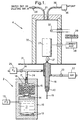
- the EFID according to the present invention is composed of two portions of a water electrolyser 2 and an FID 4.
- the water electrolyser 2 consists of a container 10 for holding water 11 with KOH (typically 0.4 molar concentration) and two nickel mesh electrodes 12 connected to an external power supply 13 by means of electrical wires.
- KOH typically 0.4 molar concentration
- the generated H 2 /O 2 premixed gas mixture passes through a membrane 14, e.g., a teflon membrane, for partial separation from water mist.
- the gas mixture is further dried by silica gel drying material 15 disposed in a chamber 16 on the other side of the membrane 14.
- the dryed gas mixture is passed through a frit flow restrictor 17 to a flame source in the form of a conduit 18.
- a column or a tube 19 for directing a sample of GC effluent or external air to the upper edge of the conduit 18.
- the tube 19 is sealed inside the conduit 18 by a seal 20.
- the H 2 /O 2 gas mixture is directed to the upper open edge of the conduit 18 where it mixes with the sample gas flowing through the tube 19 and feeds a flame 21.
- the flame can be surrounded by auxiliary air directed thereto from a source 22, via a control valve 23.
- the conduit 24 directing the flow of dryed gas to tube 18, is also connected to a source of hydrogen 25, the flow of which to the conduit 24 is controlled by a valve 26.
- both valves 23 and 26 are opened, while the electrolyser 2 is off, the electrolyser FID (EFID) is converted to an FID.
- Charged carriers produced by the flame 21 are collected by a collector electrode 27 biased by a typical voltage of -200V.
- the thusly produced current is amplified by amplifier 28 and the amplified signal can then be further processed and displayed by a computer or recording device 29.
- the flame 21 and collector electrode 27 are protected by an electrical and wind shield 30 mounted on a base 31.
- the air pump 36 is activated, tube 19 is open to the air and valve 23 is partially opened to allow external air sampling.
- valve 23 can be partially or fully opened, allowing the addition of diluting external air to the flame, in addition to the electrolyser's gases. This additional air is sometimes desirable for reducing water condensation or for preventing flame quenching by a large amount of hydrocarbon eluting from the GC.
- the water electrolyser 2 may have the dimensions of 66 mm diameter and 112 mm long, very similar in its dimensions to a standard beverage can. Its lower volume contains up to 120 ml water with 3 grams of KOH added to increase the water conductivity.
- the two round pieces of nickel mesh electrodes 12 are electrically separated at the bottom of the container, serving for the actual water electrolysis. These meshes are connected to a standard power supply operated typically at 2.6 Volt, 1.5 Ampere with total power consumption of 4 Watts. Under these conditions, about 18 ml/min of premixed stoichiometric H 2 /O 2 gas mixture is formed. The gas mixture passes through an upper teflon membrane 14, separating the water mist formed by the gas bubbles during the electrolysis.
- the gas mixture is further passed through a water drying material 15, typically silica gel.
- the volume of the drying material is calculated to be just enough for the water treated below, and is replaced or redried in an oven at each water addition cycle.
- the 120 ml water enables about 100 ml water consumption.
- the water consumption is 12 ml/day, thus this relatively small electrolyser provides the total gas consumption of the EFID for over a week and at 1 Ampere it can even last for 12 days.
- a larger water electrolyser with up to 1 liter water volume and having a separate dripping chamber and drying material tube, may continuously operate close to 3 months.
- the H 2 /O 2 unseparated mixture flows through a frit flow restrictor element 17, e.g., a 100 ml/min standard element.
- This frit element has a dual purpose: it acts as a flame arrestor to ensure the safety of the electrolyser, so as to eliminate a possible danger of flame flashback into the electrolyser.
- the frit element builds a low pressure of a fraction of an atmosphere in the electrolyser, helping to stabilize the output flow rate of the electrolyser.
- the FID 4 is a standard FID modified to increase the heat transfer from the base 31 to the charge collector, in order to avoid water condensation, which presents a problem due to the lack of high flow rate of diluting air which is conventionally used.
- the sample to be analyzed is fed from the GC tube 19 ending near the flame 21.
- the sample is swept by the H 2 /O 2 gas mixture into the flame where it is combusted to form electric current as in a conventional FID.
- the sample can be fed either from an additional co-axial air flow or through the tube with prior mixing with the combustible gas mixture, or through both these ways simultaneously. It was found that the flow of the H 2 /O 2 gases through the flame is sufficient to act as a Ventury pump inducing a flow of external air through a short central tube. Thus, when the tube is properly adjusted, an air pump is not essential for the measurement of total organic compounds in air.
- the EFID structure should, however, be thermally insulated to avoid water condensation if it is heated only by the flame.
- the charged particles which are produced are collected in the normal way by the electrically biased collector 27 and is recorded versus time.
- the source of the flame is biased while the collector is directly connected to the current amplifier.
- the source of the flame in the FID according to the present invention is narrower than usual, since it emanates from a hole having a diameter of 250 ⁇ to ensure the lack of flashbacks, as the flame cannot propagate back through a small hole of a diameter such as 250 ⁇ .
- No external hydrogen, air or helium is used except the normal column flow of helium or nitrogen. In the event hydrogen is used as a carrier gas, the flame becomes slightly hydrogen rich without any major perturbation.
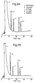
- FIG. 2 there is illustrated a comparison between chromatograms obtained with a conventional FID and according to the present invention, with an EFID.
- a 0.2 ⁇ L solution of methanol a having 20 ppm (volume) concentration of toluene b , octane c , xylene d and nonane e , injected into a 6 meter long capillary column with 0.2 mm ID, having 1 ml/min helium carrier gas flow rate.
- the 0.2 ⁇ L sample was split 100 times and in consideration of the specific gravity of the compounds, about 35 picograms of each molecules b to e was analyzed.
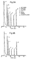
- FIG. 3 An additional comparison between a conventional FID and an EFID according to the present invention is shown in Fig. 3.
- a 0.2 ⁇ L solution of methanol with the indicated compounds at 10 -3 volume concentration was injected to the column as described with reference to Fig. 2 and with the same split ratio of 100.
- a minor problem may exist with the EFID in that a possible flame blow-off may occur when a large amount of solvent is eluted.
- This problem does not exist, but with splitless injections of over one microlite solvent into bigger tubes (columns), this problem may exist and can be solved by the addition of coaxial air flow at a low flow rate.
- This coaxial air flow can be provided by a miniature pump operated only during the solvent elution time and by using room air. Note that the use of premixed stoichiometric O 2 /H 2 flame results in a minimal background increase of about 1 picoAmpere by the addition of coaxial room air. Alternatively the flame can be sensed through its background current, followed by an automatic reignition.
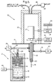
- FIG. 4 there is shown another embodiment of the invention of an Electrolyzer powered Pulsed FID (EPFID).
- a pulsed flame is a flame which, once ignited, propagates to the gas source and self-terminates. It can then be reignited periodically or triggered in an external manner.
- the container 10 of the electrolyser 2 is divided by a partition 40 into two chambers 42 and 44, which chambers are in fluid communication with each other.
- an electrode 46, 48 forming a hydrogen generating cathode side and an oxygen generating anode side.
- Each side is provided with a pressure releasing frit 50, 52 and/or a check valve, in order to minimize pressure difference between the two sides.
- Such an electrolyser produces a hydrogen rich gas mixture to allow a larger amount of air to be sampled.
- a solenoid valve 54 for effecting the introduction of the gases into the FID 56 in a pulsed manner.
- the pulsed FID is built as a closed pulsed flame combustion cell having an ignitor 58 positioned thereabove for easy repetitive ignition.
- the structure of the charge collector 60 is configured as a disc, and is mounted in the shield 62 by means of an insulator 64.
- Fig. 4 was described as an embodiment suitable for use as an EPFID, it should be noted that both electrolysers shown in Figs. 1 and 4 can be operated as EFID or EPFID.
- the ignited flame propagates in the chamber and consumes the H 2 /O 2 gas mixture until its extinction, since it cannot propagate through the narrow diameter gas entrance.
- the continuous gas flow expels the combusted water until fresh combustible gas mixture arrives at the igniter for reignition.
- the ions formed in the pulsed flame are collected and detected either in the usual way, or with a gated amplifier or AC-DC conversion system, such as an electronic peak detecting system.
- the EPFID offers several advantages, especially for a field portable FID, in the measurement of total hydrocarbon in air, or other gases or in the detection of leaks of organic compounds:
- NPD Nitrogen Phosphorus Detector
- the NPD is another popular GC detector. It is based on a partial combustion of the sample compounds with low hydrogen flow rate of 3-4 ml/min and FID like co-axial flow of air around an electrically heated bead. Organo phosphorus or nitrogen compounds are pyrolyzed and form negative CN - and PO - 2 ions at the surface of the bead that produces the detected current.
- the water electrolyzer of the EFID can provide a low flow rate of H 2 /O 2 mixture instead of the pure hydrogen used and thus, eliminate the need for a pure hydrogen source and its delicate low flow rate stabilization.
- the addition of small oxygen flow rate has no observed effect on any of the NPD performance parameters.
- the electrolyzer powered (NPD) (ENPD) is schematically illustrated in Fig. 5.
- the ENPD is similar to the EFID of Fig. 1 with the difference that the FID portion is replaced by an NPD structure.
- the NPD structure 70 comprises a ceramic bead 72, disposed above the combustible gas source 74 and being electrically heated and thermally controlled by controller 76. Typical bead temperatures are 600-800°C, and thus the bead also replaces the flame igniter.
- Electrolyzer 2 provides a low flow rate (i.e., 6 ml/min) of hydrogen and oxygen gas mixture that is further diluted with the air that is introduced and flow regulated by valve 23.
- the sample compounds are mixed with the electrolyzer produced gases and pyrolyzed due to their partial combustion in the usual manner on the bead to produce the negatively charged ions from nitrogen or phosphorus containing compounds.
- the bead is usually biased at a negative potential to repel negative ions while the gas source 74 can either be grounded or biased at a low positive potential (phosphorus detection) or negative potential (nitrogen detection).
- the gas source 74 can either be grounded or biased at a low positive potential (phosphorus detection) or negative potential (nitrogen detection).
- an FID is also mounted, and thus, the same electrolyzer used for the EFID could be used for ENPD with the great benefit of removal of the pure hydrogen source from the laboratory.
- the electrolyzed powered flame can also be used in several other flame based detectors. Most important are the flame based detectors that produce simpler species that are amenable for easier detection by other means including:
Description
- The present invention relates to flame based analyzing methods and apparatus, and particularly to a method and detector apparatus for detecting the presence and/or concentration of one or more chemical substances therein by igniting a combustible gas mixture containing the sample to produce a flame, and detecting a characteristic of the resulting flame.
- The Flame Ionization Detector (FID) is the most popular and widely used detector of Gas Chromatograph (GC) instruments. It is also used as a portable or stationary instrument for monitoring organic compound concentrations in air and other gases and gas mixtures. Recently, it was also employed as the detector of choice in Supercritical Fluid Chromatograph (SFC) instruments.
- Traditionally, the FID is based on a hydrogen diffusion flame where a hydrocarbon free (zero grade) hydrogen gas is fed through a flame tip (jet) surrounded by a coaxially much higher flow of purified (zero grade) air. Typically, helium gas is also added to the central hydrogen flow, as a make up gas to further enhance the performance of FID as a GC detector. Examples of the gas flow rates are: 30 ml/min hydrogen, 30 ml/min helium and 300-400 ml/min air.
- The operation of an FID is based on H2/O2 combustion decomposition of organic compounds, while forming some CH radicals, followed by the flame chemical ionization reaction CH+O -> CHO+ + e-. The emerging flame induced current is then measured and it is proportional to the flux of organic compounds over 5-7 decades linear dynamic range. Typical flame chemical ionization yield is 15 milliCoulomb per gram carbon. The ionization response is selective to carbon atoms only and is generally uniform among the organic compounds, however, secondary molecular effects exist and CO, CO2, CS2 are practically undetectable while certain hetero atoms, such as organo oxygen or nitrogen, reduce the carbon detection in those compounds. While the vast majority of FID's are operated with air, some studies have been performed with pure oxygen instead of air in the hydrogen diffusion flame and a very limited number of investigators have studied the effect of gas composition in premixed hydrogen air flames. FID operated with premixed H2/O2 alone is not used, probably due to the danger of flashbacks and penetration of the flame through the flame tip to the gas source in an unsafe or controlled way. Hence, the hydrogen diffusion FID became the GC industry standard detector of choice due to its sensitivity, carbon selectivity, large linear dynamic range and simple and robust operation.
- In spite of the above-described desirable features, the FID suffers from one major disadvantage, which is a large gas consumption. This results in several undesirable features:
- 1) High cost of gases.
- 2) High cost of instrumentation and installation.
- 3) Low safety, since a compressed hydrogen gas cylinder is a major hazard in the laboratory, as this gas is flammable and liable to explode in air.
- 4) High weight and large size of the instrument, due to the gas cylinders or sources.
-
- Recently, there is a growing use of hydrogen and zero grade air generators. Hydrogen is generated through the electrolysis of water and then separated from the co-generated oxygen by a polymeric or palladium membrane and compressed to a stabilized pressure of several atmospheres, as well as passing final stages of purification before the usual delivery into the GC. Room air is compressed to the usual delivery pressure by a mechanical compressor and then its hydrocarbon residual content is removed to a low acceptable level, usually through catalytic combustion, such as on a heated platinum wire. Again, the available instrumentation is expensive, bulky and requires excessive maintenance.
- U.S. Patent 5,153,673 (Amirav) discloses a pulsed flame ionization method and device in which pure hydrogen that can be generated by water electrolysis is used. This patent specifically teaches the separation of hydrogen from oxygen prior to its use.
- Similarly, U.S. Patent 2,991,158 (Harley, et al.) also teaches the separation of hydrogen from oxygen, to be separately fed into a flame ionization detector.
- The flame ionization and flame emission detector disclosed in U.S. Patent 3,661,533 (David, et al.) is a standard detector based on the use of two gas inlets, one inlet for introducing hydrogen and the other for introducing air which can be enriched with other gases.
- In conventional water electrolysis such as that described above, water is electro-chemically separated into hydrogen and oxygen gases. While for general use in a hydrogen generator the hydrogen must be separated, purified and compressed, it has been discovered that for FID usage, no such separation and purification is required, and a premixed (stoichiometric) H2/O2 gas composition mixture can be used. In addition, the FID imposes no gas conductance barrier; thus, only a few millibar pressure difference in the electrolyser is enough to drive the gas mixture to the detector. In other words, it has been found that FID can be powered by a simple water electrolysis that, in contrast to the conventionally used hydrogen and zero air generators, is characterized by the following characteristics:
- 1. The hydrogen gas generated is not thoroughly cleaned or separated from the oxygen;
- 2. Oxygen is provided to the flame instead of air;
- 3. Oxygen is provided to the flame from a water electrolyser instead of air;
- 4. The FID can be powered by premixed H2/O2 gases instead of the commonly used hydrogen diffusion air flame;
- 5. Water vapor are only partially removed, since without condensation the vapor is harmless to the flame;
- 6. The electrolysis generated gases do not have to be compressed and pressure stabilized. In fact, the total gas flow rate is controlled by the electrolysis current that acts as an electronic flow control, creating a small driving pressure gradient;
- 7. The water electrolysis provides "zero grade" gases without hydrocarbon impurities;
- 8. A relatively low total combustible gas flow rate can sustain a stable flame, and
- 9. The FID can be powered by a near stoichiometric H2/O2 gas mixture.
-
- The present invention is based on the replacement of air and hydrogen cylinders or separate hydrogen and air generators, with a very simple water electrolyser which provides an unseparated (stoichiometric) H2/O2 gas mixture. Accordingly, the hydrogen diffusion flame with air is replaced by a premixed near stoichiometric H2/O2 flame, where advantageously the flame source and gas line are structured to prevent flame flashbacks.
- Electrolyser powered FID (EFID) of the present invention possesses the following main advantages:
- 1. Reduced cost of operation. The price of distilled water is negligible compared to that of the gases it replaces, while the cost of this simple electrolyser is much lower than the conventional hydrogen and zero grade air generators or empty gas cylinders and their pressure regulators, gas valves, tubes and pneumatics involved and the safety requirements of hydrogen handling.
- 2. The EFID is safer. No compressed hydrogen (and air) is required and only a few milliliters of combustible gas mixture is stored at any time. The total combustible gas flow rate is also much smaller and thus, even if uncombusted, this mixture is easily diluted in air to a safe unignitable diluted level.
- 3. Independent total gas supply. The EFID can be operated with automatic water introduction while eliminating the dependency on external gas sources and its shipment, storage and cylinder exchange. In total organic compound analysis in air, the partial air pressure or presence of hydrogen does not affect the results, since the air sample is a small part of the electrolyser H2/O2 gas mixture, in contrast to a conventional FID in which the air supplied contains both the sample, as well as the required oxygen.
- 4. Improved sensitivity. The EFID is inherently operated with "zero grade" gases without any hydrocarbon impurities. Thus, its noise level is usually lower than that of FID. When operated at a relatively high combustible gas mixture flow rate, its chemical ionization yield is higher than that of FID. These two aspects combined enable a higher sensitivity of the EFID.
- 5. Enhanced portability. The EFID provides the ultimate in FID portability. The electrolyser according to the invention weighs only about 450 grams and consumes much less energy (and water) than its alternatives. Also, it does not require a license for transporting compressed hydrogen. The EFID is characterized by the smallest size, lowest weight, lowest energy consumption and lowest water consumption, in comparison with all of the gas cylinders or generator alternatives available today.
-
- It is therefore a broad object of the present invention to provide an improved method for producing a flame for analysing a sample by flame ionization.
- It is a further object of the invention to provide an improved detection apparatus for producing a flame for analysing a sample by flame ionization.
- According to the present invention, there is therefore provided a flame ionization method of analysing a sample by introducing the sample into an enclosure having a hydrogen and oxygen flame and detecting charge carriers produced by the combustion of organic matter in the flame to determine one or more chemical compounds in the sample, said method characterized by the steps of generating, by means of an electrolyser, a hydrogen and oxygen gas mixture by water electrolysis; feeding said gas mixture via a flame source having an opening sufficiently small to prevent a flame flashback towards said electrolyser; igniting said gas mixture to produce a flame, and heating said enclosure to a temperature sufficient for preventing water condensation in said enclosure.
- The invention further provides a flame ionization detector apparatus for analysing a sample in order to determine the identity and/or concentration of one or more chemical substances therein, including inlet means for introducing a premixed combustible gas mixture therein, feeding means for introducing the sample into said premixed combustible gas mixture, ignitor means for igniting the combustible gas mixture to produce a flame inside an enclosure, and detector means for detecting charge carriers formed from the resulting flame to determine the identity and/or concentration of one or more chemical substances in the sample, characterised in that said apparatus comprises water electrolyser means for generating said premixed combustible gas mixture and for directing said gas mixture to said inlet means; flame source means having an opening sufficiently small for preventing a flame flashback towards said electrolyser, and heating means for heating said enclosure to a temperature sufficient to prevent water condensation in said enclosure. The invention will now be described in connection with certain preferred embodiments with reference to the following illustrative figures so that it may be more fully understood.
- With specific reference now to the figures in detail, it is stressed that the particulars shown are by way of example and for purposes of illustrative discussion of the preferred embodiments of the present invention only and are presented in the cause of providing what is believed to be the most useful and readily understood description of the principles and conceptual aspects of the invention. In this regard, no attempt is made to show structural details of the invention in more detail than is necessary for a fundamental understanding of the invention, the description taken with the drawings making apparent to those skilled in the art how the several forms of the invention may be embodied in practice.
- In the Drawings:
- Fig. 1 is a schematic, cross-sectional view of an electrolyser powered flame ionization detector according to the present invention.
- Fig. 2 are chromatograms of a conventional FID and an EFID according to the invention;
- Fig. 3 are further chromatograms obtained by using different compounds with a conventional FID and an EFID according to the present invention;
- Fig. 4 is another embodiment of an EFID according to the present invention, and
- Fig. 5 is a cross-sectional view of an electrolyser powered nitrogen phosphorous detector according to the present invention.
-
- The EFID according to the present invention is composed of two portions of a
water electrolyser 2 and anFID 4. Thewater electrolyser 2 consists of acontainer 10 for holdingwater 11 with KOH (typically 0.4 molar concentration) and twonickel mesh electrodes 12 connected to anexternal power supply 13 by means of electrical wires. The generated H2/O2 premixed gas mixture passes through amembrane 14, e.g., a teflon membrane, for partial separation from water mist. The gas mixture is further dried by silicagel drying material 15 disposed in achamber 16 on the other side of themembrane 14. The dryed gas mixture is passed through a frit flow restrictor 17 to a flame source in the form of aconduit 18. Inside theconduit 18 there is disposed a column or atube 19 for directing a sample of GC effluent or external air to the upper edge of theconduit 18. Thetube 19 is sealed inside theconduit 18 by aseal 20. Hence, the H2/O2 gas mixture is directed to the upper open edge of theconduit 18 where it mixes with the sample gas flowing through thetube 19 and feeds aflame 21. The flame can be surrounded by auxiliary air directed thereto from asource 22, via acontrol valve 23. Theconduit 24 directing the flow of dryed gas totube 18, is also connected to a source ofhydrogen 25, the flow of which to theconduit 24 is controlled by avalve 26. When bothvalves electrolyser 2 is off, the electrolyser FID (EFID) is converted to an FID. - Charged carriers produced by the
flame 21 are collected by acollector electrode 27 biased by a typical voltage of -200V. The thusly produced current is amplified byamplifier 28 and the amplified signal can then be further processed and displayed by a computer orrecording device 29. Theflame 21 andcollector electrode 27 are protected by an electrical andwind shield 30 mounted on abase 31. There is also provided aflame ignitor 32,water exit tube 33, controlled byvalve 34, and anair pump 36 communicating with the interior of theshield 30 by means of apipe 38. When the EFID is used as an air analyser, theair pump 36 is activated,tube 19 is open to the air andvalve 23 is partially opened to allow external air sampling. Alternatively,valve 23 can be partially or fully opened, allowing the addition of diluting external air to the flame, in addition to the electrolyser's gases. This additional air is sometimes desirable for reducing water condensation or for preventing flame quenching by a large amount of hydrocarbon eluting from the GC. - The
water electrolyser 2 may have the dimensions of 66 mm diameter and 112 mm long, very similar in its dimensions to a standard beverage can. Its lower volume contains up to 120 ml water with 3 grams of KOH added to increase the water conductivity. The two round pieces ofnickel mesh electrodes 12 are electrically separated at the bottom of the container, serving for the actual water electrolysis. These meshes are connected to a standard power supply operated typically at 2.6 Volt, 1.5 Ampere with total power consumption of 4 Watts. Under these conditions, about 18 ml/min of premixed stoichiometric H2/O2 gas mixture is formed. The gas mixture passes through anupper teflon membrane 14, separating the water mist formed by the gas bubbles during the electrolysis. The gas mixture is further passed through awater drying material 15, typically silica gel. The volume of the drying material is calculated to be just enough for the water treated below, and is replaced or redried in an oven at each water addition cycle. The 120 ml water enables about 100 ml water consumption. At 1.5 Ampere, the water consumption is 12 ml/day, thus this relatively small electrolyser provides the total gas consumption of the EFID for over a week and at 1 Ampere it can even last for 12 days. A larger water electrolyser with up to 1 liter water volume and having a separate dripping chamber and drying material tube, may continuously operate close to 3 months. The H2/O2 unseparated mixture flows through a frit flowrestrictor element 17, e.g., a 100 ml/min standard element. This frit element has a dual purpose: it acts as a flame arrestor to ensure the safety of the electrolyser, so as to eliminate a possible danger of flame flashback into the electrolyser. In addition, the frit element builds a low pressure of a fraction of an atmosphere in the electrolyser, helping to stabilize the output flow rate of the electrolyser. TheFID 4 is a standard FID modified to increase the heat transfer from the base 31 to the charge collector, in order to avoid water condensation, which presents a problem due to the lack of high flow rate of diluting air which is conventionally used. The sample to be analyzed is fed from theGC tube 19 ending near theflame 21. The sample is swept by the H2/O2 gas mixture into the flame where it is combusted to form electric current as in a conventional FID. In the analysis of total organic compound in air, the sample can be fed either from an additional co-axial air flow or through the tube with prior mixing with the combustible gas mixture, or through both these ways simultaneously. It was found that the flow of the H2/O2 gases through the flame is sufficient to act as a Ventury pump inducing a flow of external air through a short central tube. Thus, when the tube is properly adjusted, an air pump is not essential for the measurement of total organic compounds in air. The EFID structure should, however, be thermally insulated to avoid water condensation if it is heated only by the flame. - The charged particles which are produced are collected in the normal way by the electrically biased
collector 27 and is recorded versus time. In other FID structures, the source of the flame is biased while the collector is directly connected to the current amplifier. The source of the flame in the FID according to the present invention is narrower than usual, since it emanates from a hole having a diameter of 250µ to ensure the lack of flashbacks, as the flame cannot propagate back through a small hole of a diameter such as 250µ. No external hydrogen, air or helium is used except the normal column flow of helium or nitrogen. In the event hydrogen is used as a carrier gas, the flame becomes slightly hydrogen rich without any major perturbation. - Referring to Fig. 2, there is illustrated a comparison between chromatograms obtained with a conventional FID and according to the present invention, with an EFID. For the purpose of the comparison there has been used a 0.2 µL solution of methanol a having 20 ppm (volume) concentration of toluene b, octane c, xylene d and nonane e, injected into a 6 meter long capillary column with 0.2 mm ID, having 1 ml/min helium carrier gas flow rate. The 0.2 µL sample was split 100 times and in consideration of the specific gravity of the compounds, about 35 picograms of each molecules b to e was analyzed. Thus, this typical chromatograph of toluene, octane, xylene and decane at a 20 ppm concentration level in methanol (volume), was obtained by injecting about 35 picograms of each into a 6 meter narrowbore (0.20 mm ID)
tube 19. It is seen that both the amplifier noise background and ionization yield are similar in the EFID in comparison with the conventional FID. The EFID ionization yield is about linearly increased with the total gas flow or electrolyser's current used, but this yield increase may also involve a higher background noise. A careful comparison of the EFID chromatograph to the FID chromatograph reveals that the relative ionization yield of toluene and xylene compounds is slightly increased, while that of the aliphatic compounds octane and nonane is slightly reduced. This is interpreted as the result of the premixed stoichiometric composition. It was found that if hydrogen is used as a carrier gas, or the gas mixture is enriched with hydrogen through a selective oxygen depletion, this phenomenon is reduced in its magnitude. - An additional comparison between a conventional FID and an EFID according to the present invention is shown in Fig. 3. Here, a 0.2µL solution of methanol with the indicated compounds at 10-3 volume concentration was injected to the column as described with reference to Fig. 2 and with the same split ratio of 100.
- The comparison of EFID and FID chromatograms of compounds with N,S,P,Cl heteroatoms shows that with the exception of minor relative intensity increase of the aromatic compounds (see Fig. 2), the traces are very similar. Thus, it is seen that in spite of the major differences in the gas composition, the EFID is similar to FID in its operational characteristics as a carbon selective detector with about uniform carbon response and having a similar sensitivity. Also, the FID chromatogram was achieved with zero grade gases producing only 3 picoAmpere background current. When less clean gases are used, the FID noise level is increased while the electrolyser always produces "zero grade" H2/O2 mixture. A minor problem may exist with the EFID in that a possible flame blow-off may occur when a large amount of solvent is eluted. With normal use of a narrowbore tube (column), this problem does not exist, but with splitless injections of over one microlite solvent into bigger tubes (columns), this problem may exist and can be solved by the addition of coaxial air flow at a low flow rate. This coaxial air flow can be provided by a miniature pump operated only during the solvent elution time and by using room air. Note that the use of premixed stoichiometric O2/H2 flame results in a minimal background increase of about 1 picoAmpere by the addition of coaxial room air. Alternatively the flame can be sensed through its background current, followed by an automatic reignition.
- Turning to Fig. 4, there is shown another embodiment of the invention of an Electrolyzer powered Pulsed FID (EPFID). A pulsed flame is a flame which, once ignited, propagates to the gas source and self-terminates. It can then be reignited periodically or triggered in an external manner. According to this embodiment the
container 10 of theelectrolyser 2 is divided by a partition 40 into twochambers electrode pressure releasing frit conduit 24 there is introduced asolenoid valve 54 for effecting the introduction of the gases into theFID 56 in a pulsed manner. The pulsed FID is built as a closed pulsed flame combustion cell having anignitor 58 positioned thereabove for easy repetitive ignition. As seen, the structure of thecharge collector 60 is configured as a disc, and is mounted in theshield 62 by means of aninsulator 64. - While the embodiment of Fig. 4 was described as an embodiment suitable for use as an EPFID, it should be noted that both electrolysers shown in Figs. 1 and 4 can be operated as EFID or EPFID.
- The ignited flame propagates in the chamber and consumes the H2/O2 gas mixture until its extinction, since it cannot propagate through the narrow diameter gas entrance. The continuous gas flow expels the combusted water until fresh combustible gas mixture arrives at the igniter for reignition. The ions formed in the pulsed flame are collected and detected either in the usual way, or with a gated amplifier or AC-DC conversion system, such as an electronic peak detecting system. The EPFID offers several advantages, especially for a field portable FID, in the measurement of total hydrocarbon in air, or other gases or in the detection of leaks of organic compounds:
- A) The power and water consumption, as well as total weight of the EPFID, can be smaller than EFID. Since the flame is unstable, no minimal "holding" current or gas flow rate is required and the power and water consumption can be arbitrarily reduced, depending on the response time required. The PEFID can be operated at 15 Hz when 1.5 Ampere is used (depending on the chamber's volume). If the igniter is pulsed, such as with the use of spark ignition, a 0.1 Ampere can be used with 1 Hz PEFID operation and about 1 second response time. Alternatively, the gas mixture can be released by means of a solenoid valve synchronized with the pulsed ignition. An important feature of this mode of operation is that the air can be pumped continuously, thus carrying with it substantially all the water formed by the pulsed flame without any need for heating. This elimination of the need to heat the detector, reduces the EPFID power consumption. The continuous air pumping with a low compression ratio pump, such as a small conventional electronic cooling fan, also helps to trap condensable organic compounds for increased sensitivity. The preferred mode of EPFID operation is with pulses of hydrogen rich gas mixture mixed with sampled air and pulsed ignition.
- B) No flame extinction problems exist with the EPFID, since solvent induced flame extinguishing is automatically cured due to the continuous flame ignition in the EPFID. When the solvent is fully eluted and discharged from the detector, the EPFID pulsed flame is automatically and repeatedly reignited.
-
- While the major use of the electrolyser powered flame, described herein is for flame ionization detection, other flame based detectors can also benefit from the gas mixture provided by the water electrolyser. Most notable is the Nitrogen Phosphorus Detector (NPD). The NPD is another popular GC detector. It is based on a partial combustion of the sample compounds with low hydrogen flow rate of 3-4 ml/min and FID like co-axial flow of air around an electrically heated bead. Organo phosphorus or nitrogen compounds are pyrolyzed and form negative CN- and PO- 2 ions at the surface of the bead that produces the detected current. The water electrolyzer of the EFID can provide a low flow rate of H2/O2 mixture instead of the pure hydrogen used and thus, eliminate the need for a pure hydrogen source and its delicate low flow rate stabilization. In view of the large air flow rate, the addition of small oxygen flow rate has no observed effect on any of the NPD performance parameters.
- The electrolyzer powered (NPD) (ENPD) is schematically illustrated in Fig. 5. As shown, the ENPD is similar to the EFID of Fig. 1 with the difference that the FID portion is replaced by an NPD structure. The
NPD structure 70 comprises aceramic bead 72, disposed above thecombustible gas source 74 and being electrically heated and thermally controlled bycontroller 76. Typical bead temperatures are 600-800°C, and thus the bead also replaces the flame igniter.Electrolyzer 2 provides a low flow rate (i.e., 6 ml/min) of hydrogen and oxygen gas mixture that is further diluted with the air that is introduced and flow regulated byvalve 23. The sample compounds are mixed with the electrolyzer produced gases and pyrolyzed due to their partial combustion in the usual manner on the bead to produce the negatively charged ions from nitrogen or phosphorus containing compounds. The bead is usually biased at a negative potential to repel negative ions while thegas source 74 can either be grounded or biased at a low positive potential (phosphorus detection) or negative potential (nitrogen detection). Actually, today in most GCs that have an NPD an FID is also mounted, and thus, the same electrolyzer used for the EFID could be used for ENPD with the great benefit of removal of the pure hydrogen source from the laboratory. - The electrolyzed powered flame can also be used in several other flame based detectors. Most important are the flame based detectors that produce simpler species that are amenable for easier detection by other means including:
- 1) SO2 formation from sulfur compounds for their detection via lamp induced fluorescence or mass spectrometry.
- 2) SO2 formation from sulfur compounds for their further reduction to SO followed by ozone induced chemiluminescence detection. Here the EFID is used in tandam with a consecutive sulfur selective detection. The low total flow rate of the EFID is important for optimal ozone chemiluminescence detection and it forms only water that is easy to pump, thus, the vacuum pumping capacity of this detector is reduced.
- 3) NO can be formed at the electrolyzer powered flame from nitrogen compounds and be further detected by ozone induced chemiluminescence or photo ionization.
- 4) Metal atoms can be produced by the electrolyzer powered flame for their detection by the atomic absorption or fluoresence methods, or simply by their flame chemiluminescence emission. Thus, an electrolyzer powered flame photometer detector can be used for metal, and especially for alkali metal detection in water and biofluids.
-
- The use of the electrolyzer induced flame for the formation of simpler species for their determination by other means has two unique and important advantages:
- 1. The EFID can be coupled in a tandem arrangement to form a dual detector in a one compact unit. As an example the EFID provides a carbon selective detection channel, while the NO or SO2 are transferred to a second photoionization (for the NO selective detection) or ozone chemiluminescence detector for a simultaneous sulfur or nitrogen selective detection, and
- 2. The EFID is operated on a near stoichiometric oxygen/ hydrogen gas mixture. Upon combustion, this gas mixture produces clean water only. Water can be relatively easily selectively separated from all other combustion products of the sample compounds such as NO, SO2, HCl, etc. This separation can be achieved with a NAFION membrane or by cold trapping. This total separation from all the flame combustion products can provide the highest possible concentration of the sample related flame produced species that can help in minimizing the size of the required vacuum pumps (in mass spectrometers or chemiluminescence detectors) or vacuum ultra violet light absorption in photoionization detectors, etc.
-
- It will be evident to those skilled in the art that the invention is not limited to the details of the foregoing illustrated embodiments and that the present invention may be embodied in other specific forms without departing from essential attributes thereof. The present embodiments are therefore to be considered in all respects as illustrative and not restrictive, the scope of the invention being indicated by the appended claims rather than by the foregoing description, and all changes which come within the meaning and range of equivalency of the claims are therefore intended to be embraced therein.
Claims (24)
- A flame ionization method of analysing a sample by introducing the sample into an enclosure having a hydrogen and oxygen flame and detecting charge carriers produced by the combustion of organic matter in the flame to determine the identity and/or concentration of one or more chemical compounds in the sample, said method characterised by the steps of:generating, by means of an electrolyser, a hydrogen and oxygen gas mixture by water electrolysis;feeding said gas mixture via a flame source having an opening sufficiently small to prevent a flame flashback towards said electrolyser;igniting said gas mixture to produce a flame, andheating said enclosure to a temperature sufficient for preventing water condensation in said enclosure.
- The method according to claim 1, wherein the water-generated, premixed combustible gases are a nearly stoichiometric hydrogen and oxygen gas mixture.
- The method according to claim 1, wherein the water-generated, combustible gas mixture is enriched with any other gas or gas mixture.
- The method according to claim 1, wherein the water-generated, combustible hydrogen and oxygen gas mixture is enriched with hydrogen.
- The method according to claim 1, wherein the water electrolyser provides the total combustible gas requirements needed for the flame ionization detection.
- The method according to claim 1, wherein said combustible gas mixture is directed to a flame ionization detector at near atmospheric pressure without compression and pressure stabilization.
- The method according to claim 1, wherein said sample is mixed with said combustible gas mixture prior to reaching the flame.
- The method according to claim 1, wherein said sample is fed to the flame by means of air flowing around the flame.
- The method according to claim 1, wherein said sample is eluted from a column of a gas chromatograph.
- The method according to claim 9, wherein a carrier gas of the gas chromatograph is hydrogen or air.
- The method according to claim 1, wherein said sample is an organic compound in air or another gas or gas mixture.
- The method according to claim 1, wherein additional coaxial flow of air or oxygen is directed around the flame to prevent flame extinction by a large amount of hydrocarbon and/or to eliminate water condensation.
- The method according to claim 12, wherein the additional coaxial flow of air is provided by a small air pump from the surrounding room or outdoor air.
- The method according to claim 1, wherein the flame is a conventional, continuously lit flame.
- The method according to claim 1, wherein the flame is a pulsed flame.
- The method according to claim 1, wherein the EFID (Electrolyser powered Flame Ionization Detector) can also be operated as a conventional flame ionization detector with a hydrogen diffusion air flame.
- The method according to claim 1, wherein the flame-produced ions are negative ion species produced on an NPD (Nitrogen Phosphorous Detector) bead.
- The method according to claim 1, wherein the detection of charge carriers produced by the combustion of organic matter in the flame is followed by the detection of an additional characteristic of the resulting flame.
- A flame ionization detector apparatus for analysing a sample in order to determine the identity and/or concentration of one or more chemical substances therein, including inlet means (18) for introducing a premixed combustible gas mixture therein, feeding means (19) for introducing the sample into said premixed combustible gas mixture, ignitor means (32) for igniting the combustible gas mixture to produce a flame inside an enclosure (30; 62), and detector means (27; 60) for detecting charge carriers formed from the resulting flame to determine the identity and/or concentration of one or more chemical substances in the sample,
characterised in that said apparatus comprises:water electrolyser means (2) for generating said premixed combustible gas mixture and for directing said gas mixture to said inlet means (18);flame source means (74) having an opening sufficiently small for preventing a flame flashback towards said electrolyser, andheating means (31) for heating said enclosure (30; 62) to a temperature sufficient to prevent water condensation in said enclosure. - The apparatus according to claim 19, wherein said premixed combustible gas mixture is fed to the flame coaxially with said feeding means (19) for introducing the sample.
- The apparatus according to claim 19, further comprising means (22, 23) for directing air around the flame.
- The apparatus according to claim 19, further comprising a controllable valve (54) affixed in a conduit leading from said electrolyser to said flame source means (74) for effecting the introduction of said premixed gas mixture in a pulsed manner.
- The apparatus according to claim 19, further comprising valve means (26) affixed in a conduit leading from a source of hydrogen (25) to said flame source means (74), for selectively introducing hydrogen to the flame.
- The apparatus according to claim 19, further comprising a ceramic bead (72) disposed above said feeding means and being electrically connected to a temperature controller (76).
Applications Claiming Priority (2)
| Application Number | Priority Date | Filing Date | Title |
|---|---|---|---|
| IL11528795 | 1995-09-13 | ||
| IL11528795A IL115287A (en) | 1995-09-13 | 1995-09-13 | Flame-based method and apparatus for analyzing a sample |
Publications (2)
| Publication Number | Publication Date |
|---|---|
| EP0763733A1 EP0763733A1 (en) | 1997-03-19 |
| EP0763733B1 true EP0763733B1 (en) | 2002-03-13 |
Family
ID=11067983
Family Applications (1)
| Application Number | Title | Priority Date | Filing Date |
|---|---|---|---|
| EP96306613A Expired - Lifetime EP0763733B1 (en) | 1995-09-13 | 1996-09-12 | Flame ionization method and apparatus for analyzing a sample |
Country Status (5)
| Country | Link |
|---|---|
| US (1) | US5741711A (en) |
| EP (1) | EP0763733B1 (en) |
| JP (1) | JP3909099B2 (en) |
| DE (1) | DE69619750T2 (en) |
| IL (1) | IL115287A (en) |
Families Citing this family (25)
| Publication number | Priority date | Publication date | Assignee | Title |
|---|---|---|---|---|
| FR2770909B1 (en) * | 1997-11-10 | 2000-01-28 | Huu Phuoc Nguyen | APPARATUS AND METHOD FOR GAS PHASE CHROMATOGRAPHY |
| DE19755555A1 (en) * | 1997-12-13 | 1999-06-17 | Pierburg Ag | Flame ionization detector |
| US6096178A (en) * | 1998-08-24 | 2000-08-01 | Aviv Amirav | Electrolyzer device for the operation of flame ionization detectors |
| US6268913B1 (en) | 1999-02-26 | 2001-07-31 | Siemens Westinghouse Power Corporation | Method and combustor apparatus for sensing the level of a contaminant within a combustion flame |
| EP2426693A3 (en) * | 1999-12-13 | 2013-01-16 | Semequip, Inc. | Ion source |
| IL139475A0 (en) * | 2000-11-05 | 2001-11-25 | Amirav Aviv | Method and sytem for gas chromatography |
| US6780378B2 (en) | 2001-06-28 | 2004-08-24 | Gas Technology Institute | Method for measuring concentrations of gases and vapors using controlled flames |
| JP2003098153A (en) * | 2001-09-27 | 2003-04-03 | Yokogawa Electric Corp | Photoionization detector |
| AU2003258966A1 (en) | 2002-06-27 | 2004-01-19 | Control Instruments | Gas analyzer for measuring the flammability of mixtures of combustible gases and oxygen |
| US7264775B2 (en) * | 2003-01-20 | 2007-09-04 | Midwest Research Institute, Inc. | Igniter assembly |
| US6922238B2 (en) * | 2003-01-23 | 2005-07-26 | Midwest Research Institute, Inc. | Self-tuning pulse flame photometric detector system and associated method of self-tuning |
| US20070278417A1 (en) * | 2005-07-01 | 2007-12-06 | Horsky Thomas N | Ion implantation ion source, system and method |
| JP2008190942A (en) * | 2007-02-02 | 2008-08-21 | Hitachi High-Tech Science Systems Corp | Gas chromatograph system |
| US7856737B2 (en) * | 2007-08-28 | 2010-12-28 | Mathews Company | Apparatus and method for reducing a moisture content of an agricultural product |
| WO2009032190A2 (en) * | 2007-08-28 | 2009-03-12 | Transphorm, Inc. | Compact electric appliance for providing gas for combustion |
| US20100187321A1 (en) * | 2009-01-29 | 2010-07-29 | Randy Morrell Bunn | Home heating system utilizing electrolysis of water |
| IT1398065B1 (en) * | 2010-02-08 | 2013-02-07 | Geolog S P A | FIELD CHROMATOGRAPHIC GAS FOR IONIZATION OF FLAME FOR HEAVY DUTY HYDROCARBONS. |
| US9377195B2 (en) * | 2012-03-01 | 2016-06-28 | Clearsign Combustion Corporation | Inertial electrode and system configured for electrodynamic interaction with a voltage-biased flame |
| US9389207B2 (en) * | 2012-04-20 | 2016-07-12 | The Board Of Trustees Of The University Of Illinois | Portable gas analyzer |
| US9625428B2 (en) | 2013-10-11 | 2017-04-18 | Waters Technologies Corporation | Modulated flame gas flow rates in flame-based detectors |
| US10191020B2 (en) | 2014-05-16 | 2019-01-29 | Waters Technologies Corporation | Flame ionization detection burner assemblies for use in compressible fluid-based chromatography systems |
| JP6508773B2 (en) * | 2015-05-26 | 2019-05-08 | アズビル株式会社 | Flame detection system |
| WO2018223342A1 (en) * | 2017-06-08 | 2018-12-13 | 高汴娜 | Method for detecting dimethyl ether in combustible gas |
| CN113917056B (en) * | 2021-12-15 | 2022-05-13 | 常州磐诺仪器有限公司 | Hydrogen flame ionization detector system with ultralow energy consumption and material consumption |
| CN114674968B (en) * | 2022-01-19 | 2024-01-30 | 国网江苏省电力有限公司电力科学研究院 | Hydrogen source providing device and method for hydrogen flame ionization detector |
Family Cites Families (21)
| Publication number | Priority date | Publication date | Assignee | Title |
|---|---|---|---|---|
| US2991158A (en) * | 1957-11-20 | 1961-07-04 | Harley John | Apparatus for the analysis and/or detection of substances by gas chromatography |
| GB1127078A (en) * | 1965-12-21 | 1968-09-11 | Bashkirsky Nii Pererabotki Nef | Apparatus for electrolytically producing hydrogen and oxygen |
| US3455144A (en) * | 1967-10-09 | 1969-07-15 | Pan American Petroleum Corp | Apparatus for detecting hydrocarbon gas in sea water |
| US3661533A (en) * | 1969-09-22 | 1972-05-09 | Tracor | Adjustable apparatus for flame ionization and flame emission detection |
| DE2039092C3 (en) * | 1970-08-06 | 1975-02-20 | Hartmann & Braun Ag, 6000 Frankfurt | Method for achieving an ion flow of a flame ionization detector that is independent of the addition of oxygen in the sample gas |
| US3840341A (en) * | 1972-03-03 | 1974-10-08 | Ionics | Organic carbon method and analyzer |
| GB1428235A (en) * | 1972-03-08 | 1976-03-17 | Varian Associates | Flame photometric detector |
| HU177965B (en) * | 1976-12-23 | 1982-02-28 | Hiradastechnikai Gepgyar | Method and apparatus for detecting total organic material content lf gases by means of flame ionization detector |
| GB1584978A (en) * | 1978-05-30 | 1981-02-18 | Gough T A | Gas chromatography |
| US4271022A (en) * | 1978-12-18 | 1981-06-02 | Purdue Research Foundation | Detection unit with solute detector and transport system |
| SU913222A1 (en) * | 1980-07-09 | 1982-03-15 | Aleksej N Belugin | Flame-ionization gas analyzer |
| US4332664A (en) * | 1980-09-09 | 1982-06-01 | Csepel Muvek Hiradastechnikai Gepgyara | Gas producing electrolytic cell for portable devices |
| US5037518A (en) * | 1989-09-08 | 1991-08-06 | Packard Instrument Company | Apparatus and method for generating hydrogen and oxygen by electrolytic dissociation of water |
| FR2652824B1 (en) * | 1989-10-10 | 1992-03-20 | Geoservices | APPARATUS FOR PREPARING THE ELECTROLYSIS OF WATER OF A GASEOUS MIXTURE OF OXYGEN AND HYDROGEN FOR SUPPLYING AN IONIZATION FLAME. |
| IL95617A0 (en) * | 1990-09-09 | 1991-06-30 | Aviv Amirav | Pulsed flame detector method and apparatus |
| US5052805A (en) * | 1990-09-12 | 1991-10-01 | Cms Research Corporation | Ventilation unit for a flame photometric detection device |
| US5398559A (en) * | 1992-02-28 | 1995-03-21 | The Dow Chemical Company | Sample probe with temperature monitoring and/or control |
| US5442968A (en) * | 1992-12-08 | 1995-08-22 | The Dow Chemical Company | Membrane-based fluid separations apparatus |
| US5317932A (en) * | 1992-02-28 | 1994-06-07 | The Dow Chemical Company | Sample probe |
| ES2079968T3 (en) * | 1992-02-28 | 1996-01-16 | Dow Chemical Co | APPARATUS FOR THE SEPARATION OF FLUIDS BASED ON A MEMBRANE. |
| US5342494A (en) * | 1993-03-05 | 1994-08-30 | United Technologies Corporation | High purity hydrogen and oxygen production and apparatus therefor |
-
1995
- 1995-09-13 IL IL11528795A patent/IL115287A/en not_active IP Right Cessation
- 1995-12-04 US US08/566,555 patent/US5741711A/en not_active Expired - Lifetime
-
1996
- 1996-09-12 EP EP96306613A patent/EP0763733B1/en not_active Expired - Lifetime
- 1996-09-12 DE DE69619750T patent/DE69619750T2/en not_active Expired - Lifetime
- 1996-09-13 JP JP24330096A patent/JP3909099B2/en not_active Expired - Fee Related
Also Published As
| Publication number | Publication date |
|---|---|
| JP3909099B2 (en) | 2007-04-25 |
| IL115287A (en) | 2000-02-17 |
| US5741711A (en) | 1998-04-21 |
| DE69619750T2 (en) | 2002-10-02 |
| DE69619750D1 (en) | 2002-04-18 |
| JPH09138218A (en) | 1997-05-27 |
| EP0763733A1 (en) | 1997-03-19 |
| IL115287A0 (en) | 1995-12-31 |
Similar Documents
| Publication | Publication Date | Title |
|---|---|---|
| EP0763733B1 (en) | Flame ionization method and apparatus for analyzing a sample | |
| US5153673A (en) | Pulsed flame analyzing method and detector apparatus for use therein | |
| US5892364A (en) | Trace constituent detection in inert gases | |
| US4851683A (en) | Element specific radio frequency discharge helium plasma detector for chromatography | |
| KR20070050877A (en) | Ion mobility spectrometer comprising a corona discharge ionization element | |
| US5528150A (en) | Gas sampling apparatus including a sealed chamber cooperative with a separate detector chamber | |
| CA2180266C (en) | Improved pulsed discharge systems | |
| CA1261172A (en) | Atmospheric pressure helium afterglow discharge detector for gas chromatography | |
| Colón et al. | Detectors in modern gas chromatography | |
| Camuna-Aguilar et al. | A comparative study of three microwave-induced plasma sources for atomic emission spectrometry-II. Evaluation of their atomization/excitation capabilities for chlorinated hydrocarbons | |
| CN110579564B (en) | Device and method for simultaneously measuring mercury, cadmium, zinc and lead | |
| Frentiu et al. | Quenching of the OH and nitrogen molecular emission by methane addition in an Ar capacitively coupled plasma to remove spectral interference in lead determination by atomic fluorescence spectrometry | |
| Tzanani et al. | Combined pulsed flame photometric ionization detector | |
| Jin et al. | Helium direct current discharge ionization detector for gas chromatography | |
| Hill Jr et al. | Selective detection of organometallics in gas chromatographic effluents by flame photometry | |
| Broekaert et al. | Studies of a helium-operated gas-sampling Grimm-type glow discharge for the atomic emission spectrometric determination of chlorine in halogenated hydrocarbon vapors | |
| Vasnin et al. | Pulsed discharge emission detector—Application to analytical spectroscopy of permanent gases | |
| Hill Jr et al. | Ambient pressure ionization detectors for gas chromatography Part I: flame and photoionization detectors | |
| Roberts et al. | Parameter study of a hydrogen atmosphere flame ionization detector | |
| SU1295337A1 (en) | Flame ionization detector | |
| Wentworth et al. | Non-radioactive electron-capture detector operating in the pulsed mode | |
| CN113325065A (en) | Explosion detection method and device for organic waste gas | |
| SU1286989A1 (en) | Flame-ionization detector | |
| JPH088448Y2 (en) | Hydrogen flame ionization detector for gas chromatograph | |
| SU494674A1 (en) | Method for detecting organic matter |
Legal Events
| Date | Code | Title | Description |
|---|---|---|---|
| PUAI | Public reference made under article 153(3) epc to a published international application that has entered the european phase |
Free format text: ORIGINAL CODE: 0009012 |
|
| AK | Designated contracting states |
Kind code of ref document: A1 Designated state(s): DE FR GB IT NL |
|
| 17P | Request for examination filed |
Effective date: 19970724 |
|
| 17Q | First examination report despatched |
Effective date: 19990830 |
|
| GRAG | Despatch of communication of intention to grant |
Free format text: ORIGINAL CODE: EPIDOS AGRA |
|
| RTI1 | Title (correction) |
Free format text: FLAME IONIZATION METHOD AND APPARATUS FOR ANALYZING A SAMPLE |
|
| GRAG | Despatch of communication of intention to grant |
Free format text: ORIGINAL CODE: EPIDOS AGRA |
|
| GRAH | Despatch of communication of intention to grant a patent |
Free format text: ORIGINAL CODE: EPIDOS IGRA |
|
| GRAH | Despatch of communication of intention to grant a patent |
Free format text: ORIGINAL CODE: EPIDOS IGRA |
|
| REG | Reference to a national code |
Ref country code: GB Ref legal event code: IF02 |
|
| GRAA | (expected) grant |
Free format text: ORIGINAL CODE: 0009210 |
|
| AK | Designated contracting states |
Kind code of ref document: B1 Designated state(s): DE FR GB IT NL |
|
| REF | Corresponds to: |
Ref document number: 69619750 Country of ref document: DE Date of ref document: 20020418 |
|
| ET | Fr: translation filed | ||
| PLBE | No opposition filed within time limit |
Free format text: ORIGINAL CODE: 0009261 |
|
| STAA | Information on the status of an ep patent application or granted ep patent |
Free format text: STATUS: NO OPPOSITION FILED WITHIN TIME LIMIT |
|
| 26N | No opposition filed |
Effective date: 20021216 |
|
| PGFP | Annual fee paid to national office [announced via postgrant information from national office to epo] |
Ref country code: GB Payment date: 20110920 Year of fee payment: 16 Ref country code: DE Payment date: 20110923 Year of fee payment: 16 |
|
| PGFP | Annual fee paid to national office [announced via postgrant information from national office to epo] |
Ref country code: NL Payment date: 20120920 Year of fee payment: 17 |
|
| GBPC | Gb: european patent ceased through non-payment of renewal fee |
Effective date: 20120912 |
|
| REG | Reference to a national code |
Ref country code: DE Ref legal event code: R119 Ref document number: 69619750 Country of ref document: DE Effective date: 20130403 |
|
| PG25 | Lapsed in a contracting state [announced via postgrant information from national office to epo] |
Ref country code: DE Free format text: LAPSE BECAUSE OF NON-PAYMENT OF DUE FEES Effective date: 20130403 Ref country code: GB Free format text: LAPSE BECAUSE OF NON-PAYMENT OF DUE FEES Effective date: 20120912 |
|
| PGFP | Annual fee paid to national office [announced via postgrant information from national office to epo] |
Ref country code: FR Payment date: 20130919 Year of fee payment: 18 |
|
| REG | Reference to a national code |
Ref country code: NL Ref legal event code: V1 Effective date: 20140401 |
|
| PG25 | Lapsed in a contracting state [announced via postgrant information from national office to epo] |
Ref country code: NL Free format text: LAPSE BECAUSE OF NON-PAYMENT OF DUE FEES Effective date: 20140401 |
|
| PGFP | Annual fee paid to national office [announced via postgrant information from national office to epo] |
Ref country code: IT Payment date: 20140924 Year of fee payment: 19 |
|
| REG | Reference to a national code |
Ref country code: FR Ref legal event code: ST Effective date: 20150529 |
|
| PG25 | Lapsed in a contracting state [announced via postgrant information from national office to epo] |
Ref country code: FR Free format text: LAPSE BECAUSE OF NON-PAYMENT OF DUE FEES Effective date: 20140930 |
|
| PG25 | Lapsed in a contracting state [announced via postgrant information from national office to epo] |
Ref country code: IT Free format text: LAPSE BECAUSE OF NON-PAYMENT OF DUE FEES Effective date: 20150912 |