EP0766241A1 - Apparatus for reproducing a video signal - Google Patents
Apparatus for reproducing a video signal Download PDFInfo
- Publication number
- EP0766241A1 EP0766241A1 EP96118597A EP96118597A EP0766241A1 EP 0766241 A1 EP0766241 A1 EP 0766241A1 EP 96118597 A EP96118597 A EP 96118597A EP 96118597 A EP96118597 A EP 96118597A EP 0766241 A1 EP0766241 A1 EP 0766241A1
- Authority
- EP
- European Patent Office
- Prior art keywords
- speed
- reproducing
- display
- video tape
- tape recorder
- Prior art date
- Legal status (The legal status is an assumption and is not a legal conclusion. Google has not performed a legal analysis and makes no representation as to the accuracy of the status listed.)
- Granted
Links
- 239000003550 marker Substances 0.000 claims description 12
- 230000004044 response Effects 0.000 claims description 10
- 238000010586 diagram Methods 0.000 description 28
- 238000000034 method Methods 0.000 description 6
- 238000010276 construction Methods 0.000 description 5
- 238000012545 processing Methods 0.000 description 4
- 238000004891 communication Methods 0.000 description 3
- 230000002708 enhancing effect Effects 0.000 description 3
- 102100031798 Protein eva-1 homolog A Human genes 0.000 description 2
- 230000008859 change Effects 0.000 description 2
- 230000000994 depressogenic effect Effects 0.000 description 2
- 238000001514 detection method Methods 0.000 description 2
- 238000012986 modification Methods 0.000 description 2
- 230000004048 modification Effects 0.000 description 2
- 102100022907 Acrosin-binding protein Human genes 0.000 description 1
- KVTFEOAKFFQCCX-UHFFFAOYSA-N N-hexadecanoylglycine Chemical compound CCCCCCCCCCCCCCCC(=O)NCC(O)=O KVTFEOAKFFQCCX-UHFFFAOYSA-N 0.000 description 1
- 230000002950 deficient Effects 0.000 description 1
- 238000006073 displacement reaction Methods 0.000 description 1
- 230000000694 effects Effects 0.000 description 1
- 230000006872 improvement Effects 0.000 description 1
- 238000004519 manufacturing process Methods 0.000 description 1
- 238000012544 monitoring process Methods 0.000 description 1
- 238000003825 pressing Methods 0.000 description 1
- 230000007704 transition Effects 0.000 description 1
Images


Classifications
-
- G—PHYSICS
- G11—INFORMATION STORAGE
- G11B—INFORMATION STORAGE BASED ON RELATIVE MOVEMENT BETWEEN RECORD CARRIER AND TRANSDUCER
- G11B33/00—Constructional parts, details or accessories not provided for in the other groups of this subclass
- G11B33/10—Indicating arrangements; Warning arrangements
-
- G—PHYSICS
- G11—INFORMATION STORAGE
- G11B—INFORMATION STORAGE BASED ON RELATIVE MOVEMENT BETWEEN RECORD CARRIER AND TRANSDUCER
- G11B15/00—Driving, starting or stopping record carriers of filamentary or web form; Driving both such record carriers and heads; Guiding such record carriers or containers therefor; Control thereof; Control of operating function
- G11B15/02—Control of operating function, e.g. switching from recording to reproducing
- G11B15/026—Control of operating function, e.g. switching from recording to reproducing by using processor, e.g. microcomputer
-
- G—PHYSICS
- G11—INFORMATION STORAGE
- G11B—INFORMATION STORAGE BASED ON RELATIVE MOVEMENT BETWEEN RECORD CARRIER AND TRANSDUCER
- G11B27/00—Editing; Indexing; Addressing; Timing or synchronising; Monitoring; Measuring tape travel
- G11B27/10—Indexing; Addressing; Timing or synchronising; Measuring tape travel
- G11B27/102—Programmed access in sequence to addressed parts of tracks of operating record carriers
- G11B27/107—Programmed access in sequence to addressed parts of tracks of operating record carriers of operating tapes
-
- G—PHYSICS
- G11—INFORMATION STORAGE
- G11B—INFORMATION STORAGE BASED ON RELATIVE MOVEMENT BETWEEN RECORD CARRIER AND TRANSDUCER
- G11B27/00—Editing; Indexing; Addressing; Timing or synchronising; Monitoring; Measuring tape travel
- G11B27/10—Indexing; Addressing; Timing or synchronising; Measuring tape travel
- G11B27/34—Indicating arrangements
-
- G—PHYSICS
- G11—INFORMATION STORAGE
- G11B—INFORMATION STORAGE BASED ON RELATIVE MOVEMENT BETWEEN RECORD CARRIER AND TRANSDUCER
- G11B2220/00—Record carriers by type
- G11B2220/90—Tape-like record carriers
-
- Y—GENERAL TAGGING OF NEW TECHNOLOGICAL DEVELOPMENTS; GENERAL TAGGING OF CROSS-SECTIONAL TECHNOLOGIES SPANNING OVER SEVERAL SECTIONS OF THE IPC; TECHNICAL SUBJECTS COVERED BY FORMER USPC CROSS-REFERENCE ART COLLECTIONS [XRACs] AND DIGESTS
- Y10—TECHNICAL SUBJECTS COVERED BY FORMER USPC
- Y10S—TECHNICAL SUBJECTS COVERED BY FORMER USPC CROSS-REFERENCE ART COLLECTIONS [XRACs] AND DIGESTS
- Y10S715/00—Data processing: presentation processing of document, operator interface processing, and screen saver display processing
- Y10S715/974—Slider control as on-screen object in operator interface
Definitions
- the present invention relates to an apparatus for reproducing a video signal, and in particular to a reproducing apparatus such as a video tape recorder which can execute various operations such as searching for a desired record content, for example.
- Fig. 1 of the accompanying drawings there are, as shown in Fig. 1 of the accompanying drawings, arranged operation buttons 2, which indicate the reproducing speed, in addition to the operation buttons 1 such as play, fast forward and reverse buttons.
- reproducing speed to be changed to 1/10 time speed, 1/5 time speed and twice speed by pressing respective operation buttons having 1/10, 1/5 and x2 indicated on them after the play button, for example, is depressed.
- the reproducing speed may be changed by such a simple operation as to press operation buttons 2.
- the video tape recorder switches the reproducing speed in response to the amount of revolutions of the shuttle ring 4, and the reproducing speed may be continuously changed in response to the user's operation.
- buttons and the shuttle ring as shown in Figs. 1 and 2 are displayed in exclusive screen, and the reproducing speed may be indicated through the display screen.
- the reproducing speed is limited to the range which can be set by operation buttons, and there is furthermore a disadvantage in that the reproducing speed may not be continuously changed.
- an object of the present invention is to provide an apparatus for reproducing a video signal which is capable of intuitively determining the search status in searching the record content and improving a facility for use.
- an apparatus for reproducing a video signal comprising:
- the range of a reproducible reproducing speed is displayed in a graph, a recording medium is reproduced at a reproducing speed indicated on the graph, or the operation status is displayed. This enables both the reproducing speed and the operation status to be intuitively grasped, and thereby an improvement in operability is achieved.
- Fig. 3 50 generally designates a reproducing apparatus, which controls the operation of the video tape recorder (VTR) 52 by a controller 54.
- VTR video tape recorder
- the controller 54 is capable of changing the operation of the video tape recorder 52 by manipulating a mouse 56 visually confirming a predetermined display picture.
- control signals are sent out from a command memory means 58 to the video tape recorder 52 through a communication means 50 which is a data input/output circuit, and thereby the operation of the video tape recorder 52 is controlled.
- operation information of the video tape recorder 52 is inputted through the communication means 57 in this event, and information, such as the reproducing speed, time codes, etc., of the video tape recorder 52, is stored in a current status memory means 60 which is a memory circuit.
- the controller 54 is capable of setting operation modes, sending out control signals to the video tape recorder 52, and is furthermore capable of monitoring the reproduction position.
- operation data is inputted through mouse control means 62 which is a coordinate data input circuit when the mouse 56 is operated.
- the operation data is stored in a mouse button memory means 64 and a mouse cursor position memory means 66, and thereby the button operation of the mouse 56 and the coordinate data indicated by the mouse 56 are accumulated.
- a cathode ray tube (CRT) 70 is driven through a display picture forming means 68 which is a video signal processing circuit, and thereby a necessary display picture which is necessary for the operation of the video tape recorder 62 is formed on the cathode ray tube 70.
- the display picture forming means 68 displays predetermined pictures on the basis of coordinate data stored in a lever position memory means 72 and a lever icon memory means 74 which are memory circuits.
- picture display positions of a cursor (in this embodiment a symbol of a man's hand having the direct finger extended), a lever, etc., are changed on the basis of coordinate data stored in the mouse cursor position memory means 66.
- speed data of the control variable of the video tape recorder 52 is inputted to a marker speed memory means 76 which is a memory circuit, and the speed of the video tape recorder 52 is controlled on the basis of the speed data.
- a lever control means 80 which is an operation processing circuit changes the display screen of the cathode ray tube 70 and the operation of the video tape recorder 52 by controlling the whole operation of the controller 54.
- the lever control means 80 furthermore executes a predetermined procedure to thereby set the reproducing speed of the video tape recorder 52 to a reproducing speed indicated by the user through a mouse 56.
- the reproducing apparatus 50 is capable of changing the reproducing speed of the video tape recorder with ease.
- the lever control means 80 displays a predetermined display picture when the power is turned on.
- the video tape recorder 52 is set to the play mode, the display picture of the cathode ray tube 70 is changed.
- lever control means 80 outputs control data to the video tape recorder 62 through the command memory means 58, and thereby the video tape recorder 52 is initialized.
- the lever control means 80 reads in the operation status data of the video tape recorder 62 through the current status memory means 60, and on the basis of this it is detected whether or not the power of the video tape recorder 52 is turned on, and whether or not a cassette tape is charged.
- the lever control means 80 stores data of reproducible reproducing speed of the video tape recorder 52 in the current status memory means 60, and on the basis of the corresponding speed data a display picture is produced on the cathode ray tube 70.
- lever control means 80 outputs control data to the display picture forming means 68, so that a display picture as shown in Fig. 4 is displayed on the cathode ray tube 70.
- a display region AR1 is formed in the upper center, and a reset switch "RESET" is displayed on the right side.
- the lever control means 80 displays a message "DEVICE 1", which is a unit number of the video tape recorder 52, in the upper right portion of the screen.
- the lever control means 80 displays a reproducible reproducing speed of the video tape recorder 52 in bar graph (hereinafter referred to as speed control bar) below the display region AR1.
- lever control means 80 displays operation buttons of play, fast forward, reverse, stop and pause below the speed control bar.
- the lever control means 80 detects the operation through the mouse button memory means 64, and thereby changes the operation of the video tape recorder 52 through the command memory means 58 and the communication means 57.
- the lever control means 80 displays operation buttons such as "TIMECODE” indicating the time code being displayed, index using search operation buttons “-” and “+”, and a frame switching operation button “FRAME”.
- operation buttons such as "TIMECODE” indicating the time code being displayed, index using search operation buttons “-” and “+”, and a frame switching operation button “FRAME”.
- mode changing operation buttons “MODE” fade in and fade out indicating operation buttons “FADE”
- operation buttons "TIME” indicating the transition time, etc.
- lever control means 80 to output a control signal to the video tape recorder 52 when each of the display pictures is clicked as in the case of the user clicking operation buttons such as pause, and thereby the operation mode of the video tape recorder 52 may be changed using the display picture.
- the lever control means 80 displays symbols, indicating fast forwarding and reversing, at the opposite ends of the display region in the speed control bar, respectively.
- a symbol representing stop status is displayed at the central portion of the display region.
- a symbol representing stop status is displayed at the central portion of the display region.
- Figs. 8 and 9 displayed symbols respectively representing normal reproduction and reverse reproduction, the latter being equal in reproducing speed to the normal reproduction.
- lever control means 80 displays small rectangular dots between adjacent symbols when the video tape recorder 52 is capable of continuously varying the reproducing speed.
- the dots are, as shown in Fig. 10, not displayed between the symbol representing normal reproduction and the symbol representing reverse reproduction which is equal in reproducing speed to the normal reproduction.
- the lever control means 80 switches a symbol expressing the operation status of the video tape recorder 52 in response to the memory of the current status memory means 60.
- the symbol expressing stop status is changed to the symbol as shown in Fig. 11 whereas in the case of pause the symbol is changed to the symbol in Fig. 12.
- the lever control means 80 therefore forms displays of the speed control bars illustrated in Figs. 13 and 14 in the case of no cassette tape being charged and in the case of pause, respectively.
- the lever control means 80 executes the procedure shown in Fig. 15, and thereby controls the operation of the video tape recorder 52.
- the search control means 80 proceeds from the step SP21 to the step SP22, where the memory of the mouse button memory means 64 is read out, so that information as to whether or not the mouse button is operated on is read in.
- the search control means 80 goes to the step SP23, in which the position information of the mouse 56 is taken out by reading out the memory of the mouse cursor position memory means 66. Then, the search control means 80 goes to the step SP24.
- the lever control means 80 judges on the basis of the result read in the step SP22 whether or not the mouse button is pressed. When negative result is obtained, then it goes to the step SP25.
- the lever control means 80 reads out the information stored in the current status memory means 60, and then selects a symbol expressing the reproducing speed (hereinafter referred as speed icon) on the basis of the reproducing speed of the video tape recorder 52 in it and at the same time selects a display position thereof.
- the selected results are stored in a lever icon memory means 74 and a lever position memory means 72, respectively.
- a speed icon 85 which corresponds to the reproducing speed is displayed between the stop display position and the normal reproduction display position.
- speed icons 85 which represent normal reproduction and double speed reproduction are, as shown in Figs. 18 and 19, displayed at a normal reproduction display position and another display position away from normal reproduction display position toward the fast forward side, respectively.
- fast forward reproduction and fast forward speed icons 85 which represent fast forward reproduction and fast forward are, as shown in Figs. 20 and 21, displayed at corresponding display positions.
- speed icon 85 which has the inside doubly blocked so as to be easily distinguished from the fast forward speed icon 85.
- a speed icon is displayed at the corresponding position on the speed control bar in response to the reproducing speed in the case where the reproducing speed of the video tape recorder 52 is not equal to the reproducing speed which corresponds to each of the previously described display positions: for example, the reproducing speed is 1/2, 1/3, ... 1/9 times of the normal reproducing speed; and the reproducing speed is 3 and 4 times of the normal reproducing speed (for example, in the case of 1/8 time speed, the speed icon is displayed at a substantially intermediate position between the 1/5 time speed display position and the normal reproduction display position).
- the lever control means 80 updates the contents of the speed icon 85 in response to the reproducing speed, and changes the numeral in the speed icon 85 to 1/2, 1/3, ... or 1/9 in the case of 1/2, 1/3, ising, or 1/9 time speed, for example.
- the controller 54 displays a reproducible reproducing speed in a bar graph on the cathode ray tube 70, and further displays an actual reproducing speed of the video tape recorder 52 on the bar graph.
- the user can therefore intuitively grasp the reproducing speed of the video tape recorder 52, and this enables the video tape recorder 52 to be enhanced in operability.
- the controller 54 displays the operation statuses of the video tape recorder 52 except the reproducing speed (that is, stop, no cassette, and pause statuses) on the speed control bar, and therefore other than the reproducing speed the operation statuses of the video tape recorder 52 may be intuitively grasped visually confirming the speed control bar. Therefore, the video tape recorder 52 is further improved in operability.
- the lever control means 80 selects and displays a speed icon 85 according the reproducing speed as in the case of the normal reproduction.
- the lever control means 80 simultaneously changes the display of the time code on the cathode ray tube 70 in response to the data of the time code stored in the current status memory means 60.
- the lever control means 80 After executing the processing of the step SP25, the lever control means 80 returns to the step SP22, and thereby repeats the loop LOOP1 of steps SP22-SP23-SP24-SP25-SP22 until the mouse button is pressed.
- the lever control means 80 therefore moves the display position of the speed icon 85, following changes of the reproducing speed, and at the same time updates the content of the speed icon 85. Therefore, changes of the reproducing speed may be intuitively recognized on the speed control bar.
- the controller 54 is therefore capable of enhancing the video tape recorder 52 in operability.
- the lever control means 80 makes a judgement as to whether or not the speed control bar is indicated by the mouse.
- the lever control means 80 goes to the step SP27, where it judges whether or not any operation button such as play and fast forward operation buttons is indicated.
- negative result is obtained here, it goes to the step SP25. Even if the mouse is erroneously clicked, the lever control means 80 therefore continues the updating operations of the speed icon and the display position of the latter.
- the lever control means 80 goes to the step SP28, where a control command which corresponds to the operation button indicated is stored in the command memory means 58. The lever control means 80 therefore outputs a control signal to the video tape recorder 52 through the command memory means 58.
- the lever control means 80 temporally stores a desired reproducing speed in the marker speed memory means 76, and then stores a command in the command memory means 58 to provide that reproducing speed. After outputting a control signal to the video tape recorder 52, the lever control means 80 returns to the step SP22.
- the speed control bar is indicated by the mouse 56, the lever control means 80 goes to step SP29 since affirmative result is obtained in the step SP26.
- the x coordinate indicated by the mouse 56 is stored in the lever position memory means 72. Subsequently, the lever control means 80 goes to the step SP30, where the reproducing speed indicated on the speed control bar is determined from the x coordinate indicated by the mouse 56. The determined reproducing speed is stored in the marker speed memory means 76.
- the lever control means 80 proceeds to the step SP31, where a speed icon is selected on the basis of the marker speed stored in the marker speed memory means 76, and is stored in the lever icon memory means 74.
- the lever control means 80 judges whether or not the current reproducing speed stored in the current status memory means 60 is equal to the marker speed. When negative result is obtained here, it goes to the step SP33, and stores a command necessary for setting the marker speed in the command memory means 58.
- a command is sent out to the video tape recorder 52 so as to provide the indicated reproducing speed.
- the controller 54 is capable of changing the reproducing speed by clicking the mouse on the speed control bar.
- the user can therefore visually recognize a reproducible reproducing speed displayed on the bar graph, and can intuitively grasp the changing operation of the reproducing speed by changing the reproducing speed on the bar graph.
- the video tape recorder 52 is therefore enhanced in operability.
- the controller 54 is capable of efficiently displaying necessary operation buttons in a small display region by indicating the operation speed with the speed control bar.
- any change of mode is not needed each time for changing the reproducing speed.
- the reproducing speed may be therefore set with ease, and the video tape recorder 52 can be thus enhanced in operability.
- the lever control means 80 returns to the step SP22, and also when affirmative result is obtained in the step SP32, it returns to the step SP22.
- the lever control means 80 repeats the loop LOOP2 of the steps SP22-SP23-SP24-SP26-SP29-SP30-SP31-SP32-SP33-SP22, and thereby the reproducing speed of the video tape recorder 52 continuously changes.
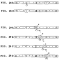
- the cursor is placed on the speed icon 85 representing the operation status of the video tape recorder 52 and then the mouse button is depressed (Fig. 29A). Subsequently in this status the mouse 56 is moved to the right. This gradually moves the display position of the speed icon 85 (as shown by the arrow a) as the cursor moves, and therefore the content is updated (Figs. 29B and 29C). In this manner, the reproducing speed of the video tape recorder 52 may be gradually changed, and the reproducing speed of the position where the mouse button is released may be set (Fig. 29D).
- the controller 54 passes only the x coordinate to the lever position memory means 72 and lever icon memory means 74, and even in the case where the mouse 56 is moved with vertical displacement, the speed icon 85 and the cursor are therefore smoothly moved.
- x coordinates of the speed icon 85 and the cursor are stored in separate storing means, and therefore the reproducing speed of the video tape recorder 52 may be smoothly changed even when the mouse 56 is moved in the x axis direction in not smooth manner. This enables the video tape recorder 52 to be enhanced in operability.
- a video tape recorder 52 may have a construction such that the actual reproducing speed of the video tape recorder 52 is detected and that reproducing speed is stored in the lever position memory means in the step SP25, whereby the reproducing speed is gradually changed in response to commands (for example, a video tape recorder which gradually reduces the reproducing speed and then outputs a still picture when a pause command is outputted).
- commands for example, a video tape recorder which gradually reduces the reproducing speed and then outputs a still picture when a pause command is outputted.
- the speed icon 85 is gradually updated in response to the actual reproducing speed of the video tape recorder 52, and thereby the operation status or the like of the video tape recorder can be further intuitively grasped.
- the video tape recorder is enhanced in operability continuously changing the reproducing speed without switching the mode as in the case of using a shuttle ring.
- the reproducible reproducing speed of the video tape recorder 52 is displayed in a bar graph, and the operation status of the video tape recorder 52 is displayed on the bar graph. Furthermore, the reproducing speed of the video tape recorder 52 is set on the bar graph. Therefore, the reproducing speed of the video tape recorder 52 may be intuitively grasped, and may be changed by simple operation. As a result, the video tape recorder 52 is enhanced in operability.
- the operation is changed using the mouse.
- the present invention is not limited to this, and various kinds of data input means, such as a write pen, a tablet, a touch screen, may be widely used.
- a roller and an execute button for example, may be used.
- a joystick and an execute button or a plus and minus operation buttons and an execute button may be combined.
- a speed control bar may be displayed superimposing it over a reproduced picture.
- a reproducible speed is horizontally displayed in bar graph, but the present invention is not limited to this.
- the reproducible speed may be displayed vertically or diagonally. Further, the reproducible speed may be displayed in a desired curve such as an arc and a spiral.
- the present invention is not limited to this.
- the present invention may be widely applied to reproduction units which output reproduced signals from various recording media such as a compact disk player.
- the reproducible region is displayed in a bar graph, and a reproducing position and a reproducing marker position are indicated in the graph.
- the present invention therefore provides a reproducing apparatus which is capable of visually recognizing the search status, and is thereby capable of enhancing operability of the reproducing apparatus.
- the reproducible speed is displayed in a bar graph, and a reproducing speed is indicated on the graph.
- the present invention therefore provides a reproducing apparatus which is therefore capable of intuitively and easily grasping the reproducing speed efficiently using small display regions, and is thereby capable of enhancing the operability thereof.
Abstract
Description
- The present invention relates to an apparatus for reproducing a video signal, and in particular to a reproducing apparatus such as a video tape recorder which can execute various operations such as searching for a desired record content, for example.
- In the video tape recorder, there have been heretofore proposed various kinds of operation methods for improving facility for use, which are capable of searching for a desired record content with ease.
- More specifically, in video tape recorders having simple constructions it is possible to search for the desired record content by repeating fast forward mode and reproducing mode, visually confirming the tape counter, for example.
- On the other hand, there is another method of searching the record content by fast forwarding while reproducing the picture, for example.
- In the method using the repeating of the fast forward mode and the reproducing mode, and the method using the fast forwarding while reproducing the picture, there is however a disadvantage such that desired record content cannot be searched with ease. For this reason, it is proposed to search the record content by referring to index signals previously recorded in a control track or the like.
- However, there is a problem in that it is hard to intuitively determine the time necessary for the search, the feed of the magnetic tape for the search, etc., in all these cases, i.e. the repeating of fast forward mode and reproducing mode, fast forwarding while reproducing the picture, and referring to index signals.
- Particularly in the video tape recorder, there is the disadvantage that it takes time also in conducting fast forward and reversing of a magnetic tape. It is considered that if in such an event, it were possible to intuitively determine the current position, a marker position, etc., under search, this kind of reproducing apparatus would be enhanced in operability and become convenient.
- More specifically, in the case where the reproducing speed is controlled using operation buttons in video tape recorders, there are, as shown in Fig. 1 of the accompanying drawings, arranged
operation buttons 2, which indicate the reproducing speed, in addition to theoperation buttons 1 such as play, fast forward and reverse buttons. - This enables the reproducing speed to be changed to 1/10 time speed, 1/5 time speed and twice speed by pressing respective operation buttons having 1/10, 1/5 and x2 indicated on them after the play button, for example, is depressed. The reproducing speed may be changed by such a simple operation as to press
operation buttons 2. - In another case of using a so-called shuttle ring 4 as shown in Fig. 2, the video tape recorder switches the reproducing speed in response to the amount of revolutions of the shuttle ring 4, and the reproducing speed may be continuously changed in response to the user's operation.
- In controllers for exclusive use in video tape recorders, the operation buttons and the shuttle ring as shown in Figs. 1 and 2 are displayed in exclusive screen, and the reproducing speed may be indicated through the display screen.
- However in the case where the operation buttons of the reproducing speed are merely arranged as shown in Fig. 1, the reproducing speed is limited to the range which can be set by operation buttons, and there is furthermore a disadvantage in that the reproducing speed may not be continuously changed.
- Moreover, there are the disadvantages that the area required to accommodate the operation buttons increases, and that it is hard to sensitively grasp the reproducing speed.
- In the case of using a shuttle ring, it is hard to start reproducing speed at a desired reproducing speed at once. Furthermore in the case of combination with an operation button such as an ordinal reproducing button, switching of the mode between the operation button and the shuttle ring is necessary for each time.
- Even if the shuttle ring is used, there is a disadvantage in that it is hard to intuitively grasp the reproducing speed, and as a result, it is still deficient in operability.
- In view of the foregoing, an object of the present invention is to provide an apparatus for reproducing a video signal which is capable of intuitively determining the search status in searching the record content and improving a facility for use.
- According to the present invention, there is provided an apparatus for reproducing a video signal, the apparatus comprising:
- reproducing means for reproducing a video signal from a recording medium;
- command input means for inputting a command for controlling the operation of said reproducing means;
- display means for displaying a reproduction status of said reproducing means;
- control means for controlling said reproducing means in response to said command and to send information regarding said reproducing state to said display means; characterised in that:
- said display means is adapted to display a graph representing the range of possible reproduction speeds of said recording medium at which a video signal is reproducible, a marker on said graph representing the current speed of said recording medium, and a pointer whose position is controllable by a user using said command input means; and
- said control means is adapted, on inputting of said command, to control the reproducing means to advance or reverse said recording medium at a speed corresponding to the position of said pointer on said graph when said command was input.
- The range of a reproducible reproducing speed is displayed in a graph, a recording medium is reproduced at a reproducing speed indicated on the graph, or the operation status is displayed. This enables both the reproducing speed and the operation status to be intuitively grasped, and thereby an improvement in operability is achieved.
- The invention will be further described by way of non-limitative example with reference to the accompanying drawings, in which:-
- Fig. 1 is a schematic diagram for illustrating the conventional switching of the reproducing speed, using the operation button;
- Fig. 2 is a schematic diagram for illustrating the conventional switching of the reproducing speed, using the shuttle ring;
- Fig. 3 is a block diagram illustrating the reproducing apparatus according to one embodiment of present invention;
- Fig. 4 is a schematic diagram showing a display picture formed by the controller thereof;
- Fig. 5 is a schematic diagram showing the symbol of fast forwarding;
- Fig. 6 is a schematic diagram showing the symbol of reversing;
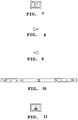
- Fig. 7 is a schematic diagram showing the symbol of stop;
- Fig. 8 is a schematic diagram showing the symbol of normal reproduction;
- Fig. 9 is a schematic diagram showing the symbol of normal speed reverse reproduction;
- Fig. 10 is a schematic diagram showing the speed control bar in the case where slow reproduction is not possible;
- Fig. 11 is a schematic diagram showing a symbol in the case where no cassette is charged;
- Fig. 12 is a schematic diagram showing a symbol of pause;
- Fig. 13 is a schematic diagram showing a symbol of the speed control bar in the case where no cassette is charged;
- Fig. 14 is a schematic diagram showing the speed control bar in the case of pause;
- Fig. 15 is a flow chart for illustrating operation of the lever control means;
- Fig. 16 is a schematic diagram showing the speed control bar in the case of 1/10 time speed slow reproduction;
- Fig. 17 is a schematic diagram showing the speed control bar in the case of 1/5 time speed slow reproduction;
- Fig. 18 is a schematic diagram showing the speed control bar in the case of normal reproduction;
- Fig. 19 is a schematic diagram showing the speed control bar in the case of high twice speed reproduction;
- Fig. 20 is a schematic diagram showing the speed control bar in the case of fast forward reproduction;
- Fig. 21 is a schematic diagram showing the speed control bar in the case of fast forward;
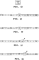
- Fig. 22 is a schematic diagram showing the speed control bar in the case of 10 time speed slow reverse reproduction;
- Fig. 23 is a schematic diagram showing the speed control bar in the case of 5 time speed slow reverse reproduction;
- Fig. 24 is a schematic diagram showing the speed control bar in the case of normal speed reverse reproduction;
- Fig. 25 is a schematic diagram showing the speed control bar in the case of high twice speed reverse reproduction;
- Fig. 26 is a schematic diagram showing the speed control bar in the case of high speed reverse reproduction;
- Fig. 27 is a schematic diagram showing the speed control bar in the case of reversing;
- Figs. 28A and 28B are schematic diagrams for illustrating the switching of the reproducing speed; and
- Figs. 29A to 29D are schematic diagrams illustrating continuous switching of the reproducing speed.
- In Fig. 3, 50 generally designates a reproducing apparatus, which controls the operation of the video tape recorder (VTR) 52 by a
controller 54. - Here, the
controller 54 is capable of changing the operation of thevideo tape recorder 52 by manipulating amouse 56 visually confirming a predetermined display picture. - More specifically, in the
controller 54 control signals are sent out from a command memory means 58 to thevideo tape recorder 52 through a communication means 50 which is a data input/output circuit, and thereby the operation of thevideo tape recorder 52 is controlled. - In the
controller 54, operation information of thevideo tape recorder 52 is inputted through the communication means 57 in this event, and information, such as the reproducing speed, time codes, etc., of thevideo tape recorder 52, is stored in a current status memory means 60 which is a memory circuit. - In such a fashion, the
controller 54 is capable of setting operation modes, sending out control signals to thevideo tape recorder 52, and is furthermore capable of monitoring the reproduction position. - Moreover in the
controller 54, operation data is inputted through mouse control means 62 which is a coordinate data input circuit when themouse 56 is operated. - Furthermore, in the
controller 54 the operation data is stored in a mouse button memory means 64 and a mouse cursor position memory means 66, and thereby the button operation of themouse 56 and the coordinate data indicated by themouse 56 are accumulated. - Moreover in the
controller 54, a cathode ray tube (CRT) 70 is driven through a display picture forming means 68 which is a video signal processing circuit, and thereby a necessary display picture which is necessary for the operation of thevideo tape recorder 62 is formed on the cathode ray tube 70. - In this event the display picture forming means 68 displays predetermined pictures on the basis of coordinate data stored in a lever position memory means 72 and a lever icon memory means 74 which are memory circuits.
- Furthermore in the display picture forming means 68, picture display positions of a cursor (in this embodiment a symbol of a man's hand having the direct finger extended), a lever, etc., are changed on the basis of coordinate data stored in the mouse cursor position memory means 66.
- In the
controller 54, speed data of the control variable of thevideo tape recorder 52 is inputted to a marker speed memory means 76 which is a memory circuit, and the speed of thevideo tape recorder 52 is controlled on the basis of the speed data. - On the other hand, a lever control means 80 which is an operation processing circuit changes the display screen of the cathode ray tube 70 and the operation of the
video tape recorder 52 by controlling the whole operation of thecontroller 54. The lever control means 80 furthermore executes a predetermined procedure to thereby set the reproducing speed of thevideo tape recorder 52 to a reproducing speed indicated by the user through amouse 56. - In such a fashion, the reproducing
apparatus 50 is capable of changing the reproducing speed of the video tape recorder with ease. - Here, the lever control means 80 displays a predetermined display picture when the power is turned on. When in this event, the
video tape recorder 52 is set to the play mode, the display picture of the cathode ray tube 70 is changed. - More specifically, the lever control means 80 outputs control data to the
video tape recorder 62 through the command memory means 58, and thereby thevideo tape recorder 52 is initialized. - Subsequently, the lever control means 80 reads in the operation status data of the
video tape recorder 62 through the current status memory means 60, and on the basis of this it is detected whether or not the power of thevideo tape recorder 52 is turned on, and whether or not a cassette tape is charged. - In this event, the lever control means 80 stores data of reproducible reproducing speed of the
video tape recorder 52 in the current status memory means 60, and on the basis of the corresponding speed data a display picture is produced on the cathode ray tube 70. - Furthermore, the lever control means 80 outputs control data to the display picture forming means 68, so that a display picture as shown in Fig. 4 is displayed on the cathode ray tube 70.
- Here in the display picture of the cathode ray tube 70, a display region AR1 is formed in the upper center, and a reset switch "RESET" is displayed on the right side.
- In this event, a picture "0:00:00:00" is displayed in the display region AR1 of the time code since the
video tape recorder 62 is in the initial status. - The lever control means 80 displays a message "
DEVICE 1", which is a unit number of thevideo tape recorder 52, in the upper right portion of the screen. - Moreover, the lever control means 80 displays a reproducible reproducing speed of the
video tape recorder 52 in bar graph (hereinafter referred to as speed control bar) below the display region AR1. - Furthermore, the lever control means 80 displays operation buttons of play, fast forward, reverse, stop and pause below the speed control bar.
- When the user clicks individual display regions manipulating the
mouse 56, the lever control means 80 detects the operation through the mouse button memory means 64, and thereby changes the operation of thevideo tape recorder 52 through the command memory means 58 and the communication means 57. - This enables the lever control means 80 to change the operation of the
video tape recorder 52 using the display pictures of the operation buttons when necessary. - In the vicinity of the pictures of the operation buttons, the lever control means 80 displays operation buttons such as "TIMECODE" indicating the time code being displayed, index using search operation buttons "-" and "+", and a frame switching operation button "FRAME". In the bottom portion, there are displayed mode changing operation buttons "MODE", fade in and fade out indicating operation buttons "FADE", operation buttons "TIME" indicating the transition time, etc..
- This enables the lever control means 80 to output a control signal to the
video tape recorder 52 when each of the display pictures is clicked as in the case of the user clicking operation buttons such as pause, and thereby the operation mode of thevideo tape recorder 52 may be changed using the display picture. - Furthermore in the lower right corner of the display screen, there are formed display regions for "SEARCH", "FADER", "REC" and "SETUP" which indicate display modes in the lower row of the display screen. The display modes at the lower row of the display screen are switched by clicking corresponding regions.
- Here, as shown in Figs. 5 and 6, the lever control means 80 displays symbols, indicating fast forwarding and reversing, at the opposite ends of the display region in the speed control bar, respectively.
- Moreover, as shown in Fig. 7 a symbol representing stop status is displayed at the central portion of the display region. At intermediate positions between the central portion symbol and respective opposite end symbols there are, as shown in Figs. 8 and 9 displayed symbols respectively representing normal reproduction and reverse reproduction, the latter being equal in reproducing speed to the normal reproduction.
- Furthermore, the lever control means 80 displays small rectangular dots between adjacent symbols when the
video tape recorder 52 is capable of continuously varying the reproducing speed. - In the case where the
video tape recorder 52 cannot perform slow reproduction, for example, the dots are, as shown in Fig. 10, not displayed between the symbol representing normal reproduction and the symbol representing reverse reproduction which is equal in reproducing speed to the normal reproduction. - In this event, the lever control means 80 switches a symbol expressing the operation status of the
video tape recorder 52 in response to the memory of the current status memory means 60. When no cassette tape is charged, for example, the symbol expressing stop status is changed to the symbol as shown in Fig. 11 whereas in the case of pause the symbol is changed to the symbol in Fig. 12. - The lever control means 80 therefore forms displays of the speed control bars illustrated in Figs. 13 and 14 in the case of no cassette tape being charged and in the case of pause, respectively.
- When an initial picture is formed in such a manner, the lever control means 80 executes the procedure shown in Fig. 15, and thereby controls the operation of the
video tape recorder 52. - More specifically, the search control means 80 proceeds from the step SP21 to the step SP22, where the memory of the mouse button memory means 64 is read out, so that information as to whether or not the mouse button is operated on is read in.
- Subsequently, the search control means 80 goes to the step SP23, in which the position information of the
mouse 56 is taken out by reading out the memory of the mouse cursor position memory means 66. Then, the search control means 80 goes to the step SP24. - Here, the lever control means 80 judges on the basis of the result read in the step SP22 whether or not the mouse button is pressed. When negative result is obtained, then it goes to the step SP25.
- Here, the lever control means 80 reads out the information stored in the current status memory means 60, and then selects a symbol expressing the reproducing speed (hereinafter referred as speed icon) on the basis of the reproducing speed of the
video tape recorder 52 in it and at the same time selects a display position thereof. The selected results are stored in a lever icon memory means 74 and a lever position memory means 72, respectively. - This enables the lever control means 80 to detect the operation of the
video tape recorder 52, and according to the detection result the operation status of thevideo tape recorder 52 is displayed on the speed control bar. - More specifically, when the reproducing speed is 1/10 time speed or 1/5 time speed of the normal reproduction as shown in Figs. 16 and 17, a
speed icon 85 which corresponds to the reproducing speed is displayed between the stop display position and the normal reproduction display position. - Similarly in cases of both normal reproduction and double speed reproduction,
speed icons 85 which represent normal reproduction and double speed reproduction are, as shown in Figs. 18 and 19, displayed at a normal reproduction display position and another display position away from normal reproduction display position toward the fast forward side, respectively. - Furthermore, in cases of fast forward reproduction and fast
forward speed icons 85 which represent fast forward reproduction and fast forward are, as shown in Figs. 20 and 21, displayed at corresponding display positions. In the case of fast forward reproduction, there is displayed thespeed icon 85 which has the inside doubly blocked so as to be easily distinguished from the fastforward speed icon 85. - A speed icon is displayed at the corresponding position on the speed control bar in response to the reproducing speed in the case where the reproducing speed of the
video tape recorder 52 is not equal to the reproducing speed which corresponds to each of the previously described display positions: for example, the reproducing speed is 1/2, 1/3, ... 1/9 times of the normal reproducing speed; and the reproducing speed is 3 and 4 times of the normal reproducing speed (for example, in the case of 1/8 time speed, the speed icon is displayed at a substantially intermediate position between the 1/5 time speed display position and the normal reproduction display position). - In this event, the lever control means 80 updates the contents of the
speed icon 85 in response to the reproducing speed, and changes the numeral in thespeed icon 85 to 1/2, 1/3, ... or 1/9 in the case of 1/2, 1/3, ......, or 1/9 time speed, for example. - In this manner, the
controller 54 displays a reproducible reproducing speed in a bar graph on the cathode ray tube 70, and further displays an actual reproducing speed of thevideo tape recorder 52 on the bar graph. - The user can therefore intuitively grasp the reproducing speed of the
video tape recorder 52, and this enables thevideo tape recorder 52 to be enhanced in operability. - Moreover, the
controller 54 displays the operation statuses of thevideo tape recorder 52 except the reproducing speed (that is, stop, no cassette, and pause statuses) on the speed control bar, and therefore other than the reproducing speed the operation statuses of thevideo tape recorder 52 may be intuitively grasped visually confirming the speed control bar. Therefore, thevideo tape recorder 52 is further improved in operability. - In the case of the
video tape recorder 52 being performing reverse reproduction as shown in Figs. 22 to 27, the lever control means 80 selects and displays aspeed icon 85 according the reproducing speed as in the case of the normal reproduction. - In the step SP25, the lever control means 80 simultaneously changes the display of the time code on the cathode ray tube 70 in response to the data of the time code stored in the current status memory means 60.
- After executing the processing of the step SP25, the lever control means 80 returns to the step SP22, and thereby repeats the loop LOOP1 of steps SP22-SP23-SP24-SP25-SP22 until the mouse button is pressed.
- In the case where the reproducing speed of the
video tape recorder 52 is gradually changed, the lever control means 80 therefore moves the display position of thespeed icon 85, following changes of the reproducing speed, and at the same time updates the content of thespeed icon 85. Therefore, changes of the reproducing speed may be intuitively recognized on the speed control bar. - The
controller 54 is therefore capable of enhancing thevideo tape recorder 52 in operability. - When on the other hand the mouse button is pressed, affirmative result is obtained in the step SP24, and thus the lever control means 80 proceeds to the step SP26.
- Here, on the basis of the detection result of the cursor position the lever control means 80 makes a judgement as to whether or not the speed control bar is indicated by the mouse.
- When negative outcome is obtained here, the lever control means 80 goes to the step SP27, where it judges whether or not any operation button such as play and fast forward operation buttons is indicated. When negative result is obtained here, it goes to the step SP25. Even if the mouse is erroneously clicked, the lever control means 80 therefore continues the updating operations of the speed icon and the display position of the latter. When on the contrary affirmative result is obtained in the step SP27, the lever control means 80 goes to the step SP28, where a control command which corresponds to the operation button indicated is stored in the command memory means 58. The lever control means 80 therefore outputs a control signal to the
video tape recorder 52 through the command memory means 58. In this manner, the user moves the cursor on the display of the operation button manipulating the mouse, and then clicks the mouse button, so that the operation of thevideo tape recorder 52 may be changed with ease. In the case where the speed of thevideo tape recorder 52 is changed in this stage, the lever control means 80 temporally stores a desired reproducing speed in the marker speed memory means 76, and then stores a command in the command memory means 58 to provide that reproducing speed. After outputting a control signal to thevideo tape recorder 52, the lever control means 80 returns to the step SP22. When on the other hand the speed control bar is indicated by themouse 56, the lever control means 80 goes to step SP29 since affirmative result is obtained in the step SP26. Here, the x coordinate indicated by themouse 56 is stored in the lever position memory means 72. Subsequently, the lever control means 80 goes to the step SP30, where the reproducing speed indicated on the speed control bar is determined from the x coordinate indicated by themouse 56. The determined reproducing speed is stored in the marker speed memory means 76. - Then, the lever control means 80 proceeds to the step SP31, where a speed icon is selected on the basis of the marker speed stored in the marker speed memory means 76, and is stored in the lever icon memory means 74.
- Subsequently, the lever control means 80 judges whether or not the current reproducing speed stored in the current status memory means 60 is equal to the marker speed. When negative result is obtained here, it goes to the step SP33, and stores a command necessary for setting the marker speed in the command memory means 58.
- When the reverse reproduction position on the speed bar is clicked by the mouse 56 (Fig. 28A), a speed icon which corresponds to the reproducing speed indicated on the speed control bar is displayed at the position, stored in the lever position memory means 72, on speed control bar (Fig. 28B).
- Furthermore, a command is sent out to the
video tape recorder 52 so as to provide the indicated reproducing speed. - In this manner, the
controller 54 is capable of changing the reproducing speed by clicking the mouse on the speed control bar. - The user can therefore visually recognize a reproducible reproducing speed displayed on the bar graph, and can intuitively grasp the changing operation of the reproducing speed by changing the reproducing speed on the bar graph. The
video tape recorder 52 is therefore enhanced in operability. - Moreover, the
controller 54 is capable of efficiently displaying necessary operation buttons in a small display region by indicating the operation speed with the speed control bar. - In the case where a combination with separate operation buttons, such as replay, is used, any change of mode is not needed each time for changing the reproducing speed. The reproducing speed may be therefore set with ease, and the
video tape recorder 52 can be thus enhanced in operability. - On completing the processing of the step SP33, the lever control means 80 returns to the step SP22, and also when affirmative result is obtained in the step SP32, it returns to the step SP22.
- When the
mouse 56 is gradually moved while it is being clicked, the lever control means 80 repeats the loop LOOP2 of the steps SP22-SP23-SP24-SP26-SP29-SP30-SP31-SP32-SP33-SP22, and thereby the reproducing speed of thevideo tape recorder 52 continuously changes. - More specifically, firstly the cursor is placed on the
speed icon 85 representing the operation status of thevideo tape recorder 52 and then the mouse button is depressed (Fig. 29A). Subsequently in this status themouse 56 is moved to the right. This gradually moves the display position of the speed icon 85 (as shown by the arrow a) as the cursor moves, and therefore the content is updated (Figs. 29B and 29C). In this manner, the reproducing speed of thevideo tape recorder 52 may be gradually changed, and the reproducing speed of the position where the mouse button is released may be set (Fig. 29D). - In this event, the
controller 54 passes only the x coordinate to the lever position memory means 72 and lever icon memory means 74, and even in the case where themouse 56 is moved with vertical displacement, thespeed icon 85 and the cursor are therefore smoothly moved. - Moreover, in this event x coordinates of the
speed icon 85 and the cursor are stored in separate storing means, and therefore the reproducing speed of thevideo tape recorder 52 may be smoothly changed even when themouse 56 is moved in the x axis direction in not smooth manner. This enables thevideo tape recorder 52 to be enhanced in operability. - A
video tape recorder 52 may have a construction such that the actual reproducing speed of thevideo tape recorder 52 is detected and that reproducing speed is stored in the lever position memory means in the step SP25, whereby the reproducing speed is gradually changed in response to commands (for example, a video tape recorder which gradually reduces the reproducing speed and then outputs a still picture when a pause command is outputted). In controlling thevideo tape recorder 52 having such a construction, thespeed icon 85 is gradually updated in response to the actual reproducing speed of thevideo tape recorder 52, and thereby the operation status or the like of the video tape recorder can be further intuitively grasped. - The video tape recorder is enhanced in operability continuously changing the reproducing speed without switching the mode as in the case of using a shuttle ring.
- According to the foregoing construction, the reproducible reproducing speed of the
video tape recorder 52 is displayed in a bar graph, and the operation status of thevideo tape recorder 52 is displayed on the bar graph. Furthermore, the reproducing speed of thevideo tape recorder 52 is set on the bar graph. Therefore, the reproducing speed of thevideo tape recorder 52 may be intuitively grasped, and may be changed by simple operation. As a result, thevideo tape recorder 52 is enhanced in operability. - In the previously-described embodiment it is stated that the operation is changed using the mouse. The present invention is not limited to this, and various kinds of data input means, such as a write pen, a tablet, a touch screen, may be widely used.
- In such cases, a roller and an execute button, for example, may be used. Furthermore, a joystick and an execute button or a plus and minus operation buttons and an execute button may be combined.
- Moreover in the embodiment previously described there is stated a case in which the operation of the video tape recorder is changed using a microcomputer. The present invention is however not restricted to this, and may be widely applied to a case where control means such as a remote commander is used.
- In such a case, a speed control bar may be displayed superimposing it over a reproduced picture.
- In the previously described embodiment, there is described a case where a reproducible speed is horizontally displayed in bar graph, but the present invention is not limited to this. The reproducible speed may be displayed vertically or diagonally. Further, the reproducible speed may be displayed in a desired curve such as an arc and a spiral.
- Moreover, the case where the record content of the video tape recorder is searched is described in the foregoing embodiment but the present invention is not limited to this. The present invention may be widely applied to reproduction units which output reproduced signals from various recording media such as a compact disk player.
- According to the present invention, the reproducible region is displayed in a bar graph, and a reproducing position and a reproducing marker position are indicated in the graph. The present invention therefore provides a reproducing apparatus which is capable of visually recognizing the search status, and is thereby capable of enhancing operability of the reproducing apparatus.
- According to the present invention, the reproducible speed is displayed in a bar graph, and a reproducing speed is indicated on the graph. The present invention therefore provides a reproducing apparatus which is therefore capable of intuitively and easily grasping the reproducing speed efficiently using small display regions, and is thereby capable of enhancing the operability thereof.
- While there has been described in connection with the preferred embodiments of the invention, it will be obvious to those skilled in the art that various changes and modifications may be made therein without departing from the invention, and it is aimed, therefore, to cover in the appended claims all such changes and modifications as fall within the scope of the invention, as defined in the appended claims.
Claims (8)
- An apparatus for reproducing a video signal, the apparatus comprising:reproducing means (52) for reproducing a video signal from a recording medium;command input means (56) for inputting a command for controlling the operation of said reproducing means;display means (70) for displaying a reproduction status of said reproducing means;control means (54) for controlling said reproducing means in response to said command and to send information regarding said reproducing state to said display means; characterised in that:said display means is adapted to display a graph representing the range of possible reproduction speeds of said recording medium at which a video signal is reproducible, a marker (85) on said graph representing the current speed of said recording medium, and a pointer whose position is controllable by a user using said command input means; andsaid control means is adapted, on inputting of said command, to control the reproducing means to advance or reverse said recording medium at a speed corresponding to the position of said pointer on said graph when said command was input.
- Apparatus according to claim 1 wherein said display means is adapted to display on said graph symbols representative of the corresponding speeds of reproduction.
- Apparatus according to claim 1 or 2 wherein said marker (85) comprises an icon representative of the operational status of said reproducing means.
- Apparatus according to claim 1, 2 or 3 wherein the centre of said graph corresponds to the recording medium being stationary and positions towards first and second ends of said graph represent forward and reverse speeds.
- Apparatus according to claim 4 wherein said display means is adapted to display symbols representing fast forward and fast reverse modes at said first and second ends and said control means is adapted to control said reproducing means to adopt a corresponding mode when said command is input when said pointer is over one of said symbols.
- Apparatus according to any one of the preceding claims wherein said command input means comprises a mouse with a button.
- Apparatus according to any one of the preceding claims wherein said reproducing means is capable of continuously varying the speed of said recording medium.
- Apparatus according to any one of the preceding claims wherein said recording medium is a magnetic tape.
Applications Claiming Priority (7)
| Application Number | Priority Date | Filing Date | Title |
|---|---|---|---|
| JP34032391 | 1991-11-28 | ||
| JP340323/91 | 1991-11-28 | ||
| JP34032391A JP3189959B2 (en) | 1991-11-28 | 1991-11-28 | Playback device |
| JP34229891A JPH05159546A (en) | 1991-11-30 | 1991-11-30 | Playback apparatus |
| JP34229891 | 1991-11-30 | ||
| JP342298/91 | 1991-11-30 | ||
| EP92310829A EP0544534B1 (en) | 1991-11-28 | 1992-11-26 | Apparatus for reproducing a video signal |
Related Parent Applications (2)
| Application Number | Title | Priority Date | Filing Date |
|---|---|---|---|
| EP92310829.4 Division | 1992-11-26 | ||
| EP92310829A Division EP0544534B1 (en) | 1991-11-28 | 1992-11-26 | Apparatus for reproducing a video signal |
Publications (2)
| Publication Number | Publication Date |
|---|---|
| EP0766241A1 true EP0766241A1 (en) | 1997-04-02 |
| EP0766241B1 EP0766241B1 (en) | 1999-10-20 |
Family
ID=26576679
Family Applications (2)
| Application Number | Title | Priority Date | Filing Date |
|---|---|---|---|
| EP92310829A Expired - Lifetime EP0544534B1 (en) | 1991-11-28 | 1992-11-26 | Apparatus for reproducing a video signal |
| EP96118597A Expired - Lifetime EP0766241B1 (en) | 1991-11-28 | 1992-11-26 | Apparatus for reproducing a video signal |
Family Applications Before (1)
| Application Number | Title | Priority Date | Filing Date |
|---|---|---|---|
| EP92310829A Expired - Lifetime EP0544534B1 (en) | 1991-11-28 | 1992-11-26 | Apparatus for reproducing a video signal |
Country Status (3)
| Country | Link |
|---|---|
| US (1) | US5832173A (en) |
| EP (2) | EP0544534B1 (en) |
| DE (2) | DE69230186T2 (en) |
Families Citing this family (29)
| Publication number | Priority date | Publication date | Assignee | Title |
|---|---|---|---|---|
| US6115037A (en) * | 1996-11-15 | 2000-09-05 | Hitachi Denshi Kabushiki Kaisha | Motion image control method and apparatus |
| US6324335B1 (en) * | 1996-11-29 | 2001-11-27 | Sony Corporation | Editing system and editing method |
| GB9718324D0 (en) * | 1997-08-30 | 1997-11-05 | Philips Electronics Nv | Video recorder |
| TW451188B (en) * | 1997-09-10 | 2001-08-21 | Sony Corp | Information recording method and apparatus and information recording medium |
| JP4045651B2 (en) * | 1997-11-19 | 2008-02-13 | ソニー株式会社 | Information processing apparatus, information processing method, and program recording medium |
| US6826350B1 (en) * | 1998-06-01 | 2004-11-30 | Nippon Telegraph And Telephone Corporation | High-speed signal search method device and recording medium for the same |
| JP2001118366A (en) * | 1999-10-20 | 2001-04-27 | Brother Ind Ltd | Device and method for detecting discontinuous position |
| JP4185243B2 (en) * | 2000-11-15 | 2008-11-26 | パイオニア株式会社 | Information recording / reproducing apparatus with ring buffer and method for monitoring ring buffer |
| JP4448650B2 (en) * | 2002-08-23 | 2010-04-14 | パイオニア株式会社 | Information processing apparatus, display method, program, recording medium for recording program, and playback apparatus |
| US20050228694A1 (en) * | 2004-04-12 | 2005-10-13 | Sanitec Industries, Inc., A California Corporation | Processing of documents with medical and other waste |
| JPWO2006022148A1 (en) * | 2004-08-25 | 2008-07-31 | パイオニア株式会社 | Information playback device |
| JP4419903B2 (en) * | 2005-04-15 | 2010-02-24 | ソニー株式会社 | INPUT DEVICE, INPUT METHOD, INPUT CONTROL PROGRAM, REPRODUCTION DEVICE, REPRODUCTION CONTROL METHOD, AND REPRODUCTION CONTROL PROGRAM |
| JP4760105B2 (en) * | 2005-04-15 | 2011-08-31 | ソニー株式会社 | Playback apparatus, playback method, and playback program |
| KR100651557B1 (en) * | 2005-11-01 | 2006-11-29 | 삼성전자주식회사 | Method for searching moving picture in wireless terminal |
| US8677257B2 (en) | 2006-08-04 | 2014-03-18 | Apple Inc. | Granular graphical user interface element |
| JP4626590B2 (en) * | 2006-08-22 | 2011-02-09 | ソニー株式会社 | RECORDING / REPRODUCING DEVICE, REPRODUCING DEVICE, RECORDING DEVICE, IMAGING RECORDING / REPRODUCING DEVICE, AND OPERATION CONTENT DISPLAY METHOD |
| KR101278240B1 (en) * | 2006-11-15 | 2013-06-24 | 삼성전자주식회사 | Method for capturing still image during reproducing moving picture |
| US7443629B1 (en) * | 2007-04-09 | 2008-10-28 | International Business Machines Corporation | Apparatus, system, and method for optimizing fast access data storage on segmented tape media |
| US20090303188A1 (en) * | 2008-06-05 | 2009-12-10 | Honeywell International Inc. | System and method for adjusting a value using a touchscreen slider |
| KR20120031399A (en) * | 2010-09-24 | 2012-04-03 | 엘지전자 주식회사 | Mobile twrminal and playback speed controlling method thereof |
| US9179103B2 (en) * | 2010-09-28 | 2015-11-03 | Alcatel Lucent | System and method for controllably viewing digital video streams captured by surveillance cameras |
| US8737821B2 (en) * | 2012-05-31 | 2014-05-27 | Eric Qing Li | Automatic triggering of a zoomed-in scroll bar for a media program based on user input |
| US9934222B2 (en) | 2014-04-22 | 2018-04-03 | Google Llc | Providing a thumbnail image that follows a main image |
| USD781318S1 (en) | 2014-04-22 | 2017-03-14 | Google Inc. | Display screen with graphical user interface or portion thereof |
| USD781317S1 (en) * | 2014-04-22 | 2017-03-14 | Google Inc. | Display screen with graphical user interface or portion thereof |
| USD780777S1 (en) | 2014-04-22 | 2017-03-07 | Google Inc. | Display screen with graphical user interface or portion thereof |
| USD829239S1 (en) * | 2017-12-08 | 2018-09-25 | Technonet Co., Ltd. | Video player display screen or portion thereof with graphical user interface |
| USD864988S1 (en) * | 2018-02-27 | 2019-10-29 | Halogen Networks, LLC | Display screen or portion thereof with graphical user interface |
| USD920363S1 (en) * | 2019-10-25 | 2021-05-25 | Eli Lilly And Company | Display screen with a graphical user interface |
Citations (7)
| Publication number | Priority date | Publication date | Assignee | Title |
|---|---|---|---|---|
| GB2124056A (en) * | 1982-07-19 | 1984-02-08 | Ricoh Kk | Video tape recorder |
| EP0186901A2 (en) * | 1984-12-24 | 1986-07-09 | Matsushita Electric Industrial Co., Ltd. | Video tape recorder |
| WO1987006415A1 (en) * | 1986-04-11 | 1987-10-22 | Ampex Corporation | Video tape recorder having status displays mode |
| US4789973A (en) * | 1985-08-22 | 1988-12-06 | Canon Kabushiki Kaisha | Recording/reproducing apparatus with dual display capability |
| EP0357909A1 (en) * | 1988-08-20 | 1990-03-14 | Nokia (Deutschland) GmbH | Remote control electrical device |
| EP0390041A2 (en) | 1989-03-28 | 1990-10-03 | Matsushita Electric Industrial Co., Ltd. | Remote-control apparatus for electronics apparatus |
| FR2663140A1 (en) * | 1990-06-08 | 1991-12-13 | Apple Computer | Control process and device for the flow of sequential information |
Family Cites Families (13)
| Publication number | Priority date | Publication date | Assignee | Title |
|---|---|---|---|---|
| US4200893A (en) * | 1978-05-17 | 1980-04-29 | Dictaphone Corporation | Instruction indicating apparatus for a record and/or playback device |
| US4210785A (en) * | 1978-09-28 | 1980-07-01 | Bell & Howell Company | Tape replay system |
| JPS58172078A (en) * | 1982-04-02 | 1983-10-08 | Sony Corp | Reproducing device |
| US4692819A (en) * | 1984-08-31 | 1987-09-08 | Ampex Corporation | Method and apparatus for controlling the position of a transported web |
| US4937037A (en) * | 1985-08-06 | 1990-06-26 | Christopher A. Griffiths | Combined inforamtion recording and graphic display device |
| JPH0679431B2 (en) * | 1986-04-12 | 1994-10-05 | ソニー株式会社 | Editing status display method |
| US4812940A (en) * | 1986-06-20 | 1989-03-14 | Olympus Optical Co., Ltd. | Dictation display for displaying present position and cue mark position information |
| US5225945A (en) * | 1988-02-24 | 1993-07-06 | Sony Corporation | Apparatus for editing pcm signals reproduced at different speeds from two memories |
| EP0390048B1 (en) * | 1989-03-28 | 1996-10-23 | Matsushita Electric Industrial Co., Ltd. | Apparatus and method for data edition |
| JP2797520B2 (en) * | 1989-09-22 | 1998-09-17 | ソニー株式会社 | Digital signal reproduction device |
| US5206767A (en) * | 1989-12-29 | 1993-04-27 | Tandy Corporation | Vcr accessory and editor |
| US5513306A (en) * | 1990-08-09 | 1996-04-30 | Apple Computer, Inc. | Temporal event viewing and editing system |
| DE69222102T2 (en) * | 1991-08-02 | 1998-03-26 | Grass Valley Group | Operator interface for video editing system for the display and interactive control of video material |
-
1992
- 1992-11-26 DE DE69230186T patent/DE69230186T2/en not_active Expired - Lifetime
- 1992-11-26 DE DE69226242T patent/DE69226242T2/en not_active Expired - Lifetime
- 1992-11-26 EP EP92310829A patent/EP0544534B1/en not_active Expired - Lifetime
- 1992-11-26 EP EP96118597A patent/EP0766241B1/en not_active Expired - Lifetime
-
1997
- 1997-08-20 US US08/914,954 patent/US5832173A/en not_active Expired - Lifetime
Patent Citations (7)
| Publication number | Priority date | Publication date | Assignee | Title |
|---|---|---|---|---|
| GB2124056A (en) * | 1982-07-19 | 1984-02-08 | Ricoh Kk | Video tape recorder |
| EP0186901A2 (en) * | 1984-12-24 | 1986-07-09 | Matsushita Electric Industrial Co., Ltd. | Video tape recorder |
| US4789973A (en) * | 1985-08-22 | 1988-12-06 | Canon Kabushiki Kaisha | Recording/reproducing apparatus with dual display capability |
| WO1987006415A1 (en) * | 1986-04-11 | 1987-10-22 | Ampex Corporation | Video tape recorder having status displays mode |
| EP0357909A1 (en) * | 1988-08-20 | 1990-03-14 | Nokia (Deutschland) GmbH | Remote control electrical device |
| EP0390041A2 (en) | 1989-03-28 | 1990-10-03 | Matsushita Electric Industrial Co., Ltd. | Remote-control apparatus for electronics apparatus |
| FR2663140A1 (en) * | 1990-06-08 | 1991-12-13 | Apple Computer | Control process and device for the flow of sequential information |
Non-Patent Citations (1)
| Title |
|---|
| "DIGITAL VIDEO DIRECTION AND SPEED CONTROLS", IBM TECHNICAL DISCLOSURE BULLETIN, vol. 34, no. 6, 1 November 1991 (1991-11-01), pages 36 - 38, XP000228342 * |
Also Published As
| Publication number | Publication date |
|---|---|
| EP0544534B1 (en) | 1998-07-15 |
| EP0766241B1 (en) | 1999-10-20 |
| DE69226242D1 (en) | 1998-08-20 |
| EP0544534A2 (en) | 1993-06-02 |
| US5832173A (en) | 1998-11-03 |
| DE69230186D1 (en) | 1999-11-25 |
| EP0544534A3 (en) | 1994-02-23 |
| DE69226242T2 (en) | 1998-11-19 |
| DE69230186T2 (en) | 2000-05-11 |
Similar Documents
| Publication | Publication Date | Title |
|---|---|---|
| EP0766241B1 (en) | Apparatus for reproducing a video signal | |
| US5202961A (en) | Sequential information controller | |
| EP0526064B1 (en) | Video editing system operator interface for visualization and interactive control of video material | |
| KR100464997B1 (en) | Editing method and controller of recording material | |
| US5760767A (en) | Method and apparatus for displaying in and out points during video editing | |
| US5008872A (en) | Optical disc reproduction apparatus which detects maximum audio signal level recorded on an optical disk | |
| CN1604033B (en) | Playback device and method of displaying menu in playback device | |
| US6115037A (en) | Motion image control method and apparatus | |
| KR100493489B1 (en) | Video material or audio and video material playback control device and method | |
| US6778223B2 (en) | Image display apparatus and method | |
| US20070273649A1 (en) | User Interface System Program and Recording Medium | |
| KR100477407B1 (en) | Editing method and controller of recording material | |
| MXPA97005547A (en) | Apparatus and method for controlling the presentation of the electr program guide | |
| EP1239672A2 (en) | Animated screen object for annotation and selection of video sequences | |
| US5050003A (en) | Image processing apparatus capable of displaying a plurality of screens | |
| JPH04236624A (en) | Control system | |
| WO2002047086A1 (en) | Recording/reproducing apparatus and record medium | |
| EP0596661B1 (en) | Controlling cassette auto changers | |
| US6313812B1 (en) | Single remote control system for plurality of audio and visual equipment | |
| JP3189959B2 (en) | Playback device | |
| EP1102274A2 (en) | Data editing apparatus, data editing method and data recording/reproducing apparatus | |
| US5953481A (en) | Reproducing apparatus having an editing function | |
| JP4364469B2 (en) | Recording / reproducing apparatus and recording medium | |
| JP4319089B2 (en) | Image processing device | |
| JP2002152684A (en) | Device and method for reproducing multiangle |
Legal Events
| Date | Code | Title | Description |
|---|---|---|---|
| PUAI | Public reference made under article 153(3) epc to a published international application that has entered the european phase |
Free format text: ORIGINAL CODE: 0009012 |
|
| AC | Divisional application: reference to earlier application |
Ref document number: 544534 Country of ref document: EP |
|
| AK | Designated contracting states |
Kind code of ref document: A1 Designated state(s): DE FR GB |
|
| 17P | Request for examination filed |
Effective date: 19970909 |
|
| 17Q | First examination report despatched |
Effective date: 19980406 |
|
| GRAG | Despatch of communication of intention to grant |
Free format text: ORIGINAL CODE: EPIDOS AGRA |
|
| GRAG | Despatch of communication of intention to grant |
Free format text: ORIGINAL CODE: EPIDOS AGRA |
|
| GRAH | Despatch of communication of intention to grant a patent |
Free format text: ORIGINAL CODE: EPIDOS IGRA |
|
| GRAH | Despatch of communication of intention to grant a patent |
Free format text: ORIGINAL CODE: EPIDOS IGRA |
|
| GRAA | (expected) grant |
Free format text: ORIGINAL CODE: 0009210 |
|
| AC | Divisional application: reference to earlier application |
Ref document number: 544534 Country of ref document: EP |
|
| AK | Designated contracting states |
Kind code of ref document: B1 Designated state(s): DE FR GB |
|
| REF | Corresponds to: |
Ref document number: 69230186 Country of ref document: DE Date of ref document: 19991125 |
|
| ET | Fr: translation filed | ||
| PLBE | No opposition filed within time limit |
Free format text: ORIGINAL CODE: 0009261 |
|
| STAA | Information on the status of an ep patent application or granted ep patent |
Free format text: STATUS: NO OPPOSITION FILED WITHIN TIME LIMIT |
|
| 26N | No opposition filed | ||
| REG | Reference to a national code |
Ref country code: GB Ref legal event code: IF02 |
|
| REG | Reference to a national code |
Ref country code: GB Ref legal event code: 746 Effective date: 20091124 |
|
| PGFP | Annual fee paid to national office [announced via postgrant information from national office to epo] |
Ref country code: FR Payment date: 20101130 Year of fee payment: 19 |
|
| PGFP | Annual fee paid to national office [announced via postgrant information from national office to epo] |
Ref country code: DE Payment date: 20101119 Year of fee payment: 19 |
|
| PGFP | Annual fee paid to national office [announced via postgrant information from national office to epo] |
Ref country code: GB Payment date: 20101118 Year of fee payment: 19 |
|
| GBPC | Gb: european patent ceased through non-payment of renewal fee |
Effective date: 20111126 |
|
| REG | Reference to a national code |
Ref country code: FR Ref legal event code: ST Effective date: 20120731 |
|
| REG | Reference to a national code |
Ref country code: DE Ref legal event code: R119 Ref document number: 69230186 Country of ref document: DE Effective date: 20120601 |
|
| PG25 | Lapsed in a contracting state [announced via postgrant information from national office to epo] |
Ref country code: GB Free format text: LAPSE BECAUSE OF NON-PAYMENT OF DUE FEES Effective date: 20111126 |
|
| PG25 | Lapsed in a contracting state [announced via postgrant information from national office to epo] |
Ref country code: FR Free format text: LAPSE BECAUSE OF NON-PAYMENT OF DUE FEES Effective date: 20111130 |
|
| PG25 | Lapsed in a contracting state [announced via postgrant information from national office to epo] |
Ref country code: DE Free format text: LAPSE BECAUSE OF NON-PAYMENT OF DUE FEES Effective date: 20120601 |