EP0770779A2 - Compressor - Google Patents
Compressor Download PDFInfo
- Publication number
- EP0770779A2 EP0770779A2 EP97100165A EP97100165A EP0770779A2 EP 0770779 A2 EP0770779 A2 EP 0770779A2 EP 97100165 A EP97100165 A EP 97100165A EP 97100165 A EP97100165 A EP 97100165A EP 0770779 A2 EP0770779 A2 EP 0770779A2
- Authority
- EP
- European Patent Office
- Prior art keywords
- piston
- cylinder
- stator
- guide
- piston guide
- Prior art date
- Legal status (The legal status is an assumption and is not a legal conclusion. Google has not performed a legal analysis and makes no representation as to the accuracy of the status listed.)
- Granted
Links
- 238000003475 lamination Methods 0.000 claims description 5
- 238000003754 machining Methods 0.000 abstract description 3
- 239000000463 material Substances 0.000 description 10
- 230000000694 effects Effects 0.000 description 9
- 239000004033 plastic Substances 0.000 description 8
- 229920003023 plastic Polymers 0.000 description 8
- 230000006835 compression Effects 0.000 description 4
- 238000007906 compression Methods 0.000 description 4
- 230000002441 reversible effect Effects 0.000 description 4
- 238000004891 communication Methods 0.000 description 3
- 238000010276 construction Methods 0.000 description 3
- 238000011065 in-situ storage Methods 0.000 description 3
- 229910052751 metal Inorganic materials 0.000 description 3
- 239000002184 metal Substances 0.000 description 3
- 230000002093 peripheral effect Effects 0.000 description 3
- 239000000835 fiber Substances 0.000 description 2
- 238000002955 isolation Methods 0.000 description 2
- 230000001050 lubricating effect Effects 0.000 description 2
- 230000003014 reinforcing effect Effects 0.000 description 2
- 229920000265 Polyparaphenylene Polymers 0.000 description 1
- UCKMPCXJQFINFW-UHFFFAOYSA-N Sulphide Chemical compound [S-2] UCKMPCXJQFINFW-UHFFFAOYSA-N 0.000 description 1
- 239000004411 aluminium Substances 0.000 description 1
- 229910052782 aluminium Inorganic materials 0.000 description 1
- XAGFODPZIPBFFR-UHFFFAOYSA-N aluminium Chemical compound [Al] XAGFODPZIPBFFR-UHFFFAOYSA-N 0.000 description 1
- 238000002048 anodisation reaction Methods 0.000 description 1
- 238000007743 anodising Methods 0.000 description 1
- 238000013459 approach Methods 0.000 description 1
- 238000001816 cooling Methods 0.000 description 1
- 238000010292 electrical insulation Methods 0.000 description 1
- 239000012777 electrically insulating material Substances 0.000 description 1
- 229920002457 flexible plastic Polymers 0.000 description 1
- 238000009499 grossing Methods 0.000 description 1
- 238000005461 lubrication Methods 0.000 description 1
- 238000012423 maintenance Methods 0.000 description 1
- 238000004519 manufacturing process Methods 0.000 description 1
- XXYTXQGCRQLRHA-UHFFFAOYSA-N metahexamide Chemical compound C1=C(N)C(C)=CC=C1S(=O)(=O)NC(=O)NC1CCCCC1 XXYTXQGCRQLRHA-UHFFFAOYSA-N 0.000 description 1
- 229960005125 metahexamide Drugs 0.000 description 1
- 238000000034 method Methods 0.000 description 1
- 238000012986 modification Methods 0.000 description 1
- 230000004048 modification Effects 0.000 description 1
- 238000000465 moulding Methods 0.000 description 1
- -1 polyphenylene Polymers 0.000 description 1
- 238000005086 pumping Methods 0.000 description 1
- 238000007789 sealing Methods 0.000 description 1
- 125000006850 spacer group Chemical group 0.000 description 1
Images


Classifications
-
- F—MECHANICAL ENGINEERING; LIGHTING; HEATING; WEAPONS; BLASTING
- F04—POSITIVE - DISPLACEMENT MACHINES FOR LIQUIDS; PUMPS FOR LIQUIDS OR ELASTIC FLUIDS
- F04B—POSITIVE-DISPLACEMENT MACHINES FOR LIQUIDS; PUMPS
- F04B35/00—Piston pumps specially adapted for elastic fluids and characterised by the driving means to their working members, or by combination with, or adaptation to, specific driving engines or motors, not otherwise provided for
- F04B35/04—Piston pumps specially adapted for elastic fluids and characterised by the driving means to their working members, or by combination with, or adaptation to, specific driving engines or motors, not otherwise provided for the means being electric
- F04B35/045—Piston pumps specially adapted for elastic fluids and characterised by the driving means to their working members, or by combination with, or adaptation to, specific driving engines or motors, not otherwise provided for the means being electric using solenoids
-
- F—MECHANICAL ENGINEERING; LIGHTING; HEATING; WEAPONS; BLASTING
- F04—POSITIVE - DISPLACEMENT MACHINES FOR LIQUIDS; PUMPS FOR LIQUIDS OR ELASTIC FLUIDS
- F04B—POSITIVE-DISPLACEMENT MACHINES FOR LIQUIDS; PUMPS
- F04B35/00—Piston pumps specially adapted for elastic fluids and characterised by the driving means to their working members, or by combination with, or adaptation to, specific driving engines or motors, not otherwise provided for
- F04B35/04—Piston pumps specially adapted for elastic fluids and characterised by the driving means to their working members, or by combination with, or adaptation to, specific driving engines or motors, not otherwise provided for the means being electric
-
- F—MECHANICAL ENGINEERING; LIGHTING; HEATING; WEAPONS; BLASTING
- F04—POSITIVE - DISPLACEMENT MACHINES FOR LIQUIDS; PUMPS FOR LIQUIDS OR ELASTIC FLUIDS
- F04B—POSITIVE-DISPLACEMENT MACHINES FOR LIQUIDS; PUMPS
- F04B39/00—Component parts, details, or accessories, of pumps or pumping systems specially adapted for elastic fluids, not otherwise provided for in, or of interest apart from, groups F04B25/00 - F04B37/00
- F04B39/0005—Component parts, details, or accessories, of pumps or pumping systems specially adapted for elastic fluids, not otherwise provided for in, or of interest apart from, groups F04B25/00 - F04B37/00 adaptations of pistons
-
- F—MECHANICAL ENGINEERING; LIGHTING; HEATING; WEAPONS; BLASTING
- F04—POSITIVE - DISPLACEMENT MACHINES FOR LIQUIDS; PUMPS FOR LIQUIDS OR ELASTIC FLUIDS
- F04B—POSITIVE-DISPLACEMENT MACHINES FOR LIQUIDS; PUMPS
- F04B39/00—Component parts, details, or accessories, of pumps or pumping systems specially adapted for elastic fluids, not otherwise provided for in, or of interest apart from, groups F04B25/00 - F04B37/00
- F04B39/0027—Pulsation and noise damping means
- F04B39/0055—Pulsation and noise damping means with a special shape of fluid passage, e.g. bends, throttles, diameter changes, pipes
- F04B39/0061—Pulsation and noise damping means with a special shape of fluid passage, e.g. bends, throttles, diameter changes, pipes using muffler volumes
-
- F—MECHANICAL ENGINEERING; LIGHTING; HEATING; WEAPONS; BLASTING
- F04—POSITIVE - DISPLACEMENT MACHINES FOR LIQUIDS; PUMPS FOR LIQUIDS OR ELASTIC FLUIDS
- F04B—POSITIVE-DISPLACEMENT MACHINES FOR LIQUIDS; PUMPS
- F04B39/00—Component parts, details, or accessories, of pumps or pumping systems specially adapted for elastic fluids, not otherwise provided for in, or of interest apart from, groups F04B25/00 - F04B37/00
- F04B39/04—Measures to avoid lubricant contaminating the pumped fluid
- F04B39/041—Measures to avoid lubricant contaminating the pumped fluid sealing for a reciprocating rod
- F04B39/042—Measures to avoid lubricant contaminating the pumped fluid sealing for a reciprocating rod sealing being provided on the piston
-
- F—MECHANICAL ENGINEERING; LIGHTING; HEATING; WEAPONS; BLASTING
- F04—POSITIVE - DISPLACEMENT MACHINES FOR LIQUIDS; PUMPS FOR LIQUIDS OR ELASTIC FLUIDS
- F04B—POSITIVE-DISPLACEMENT MACHINES FOR LIQUIDS; PUMPS
- F04B39/00—Component parts, details, or accessories, of pumps or pumping systems specially adapted for elastic fluids, not otherwise provided for in, or of interest apart from, groups F04B25/00 - F04B37/00
- F04B39/10—Adaptations or arrangements of distribution members
- F04B39/1073—Adaptations or arrangements of distribution members the members being reed valves
-
- F—MECHANICAL ENGINEERING; LIGHTING; HEATING; WEAPONS; BLASTING
- F16—ENGINEERING ELEMENTS AND UNITS; GENERAL MEASURES FOR PRODUCING AND MAINTAINING EFFECTIVE FUNCTIONING OF MACHINES OR INSTALLATIONS; THERMAL INSULATION IN GENERAL
- F16J—PISTONS; CYLINDERS; SEALINGS
- F16J1/00—Pistons; Trunk pistons; Plungers
- F16J1/10—Connection to driving members
- F16J1/24—Connection to driving members designed to give the piston some rotary movement about its axis
-
- F—MECHANICAL ENGINEERING; LIGHTING; HEATING; WEAPONS; BLASTING
- F05—INDEXING SCHEMES RELATING TO ENGINES OR PUMPS IN VARIOUS SUBCLASSES OF CLASSES F01-F04
- F05C—INDEXING SCHEME RELATING TO MATERIALS, MATERIAL PROPERTIES OR MATERIAL CHARACTERISTICS FOR MACHINES, ENGINES OR PUMPS OTHER THAN NON-POSITIVE-DISPLACEMENT MACHINES OR ENGINES
- F05C2225/00—Synthetic polymers, e.g. plastics; Rubber
- F05C2225/08—Thermoplastics
-
- F—MECHANICAL ENGINEERING; LIGHTING; HEATING; WEAPONS; BLASTING
- F05—INDEXING SCHEMES RELATING TO ENGINES OR PUMPS IN VARIOUS SUBCLASSES OF CLASSES F01-F04
- F05C—INDEXING SCHEME RELATING TO MATERIALS, MATERIAL PROPERTIES OR MATERIAL CHARACTERISTICS FOR MACHINES, ENGINES OR PUMPS OTHER THAN NON-POSITIVE-DISPLACEMENT MACHINES OR ENGINES
- F05C2251/00—Material properties
Definitions
- This invention relates to electromagnetic reciprocating compressors or pumps, particularly compressors for pumping gas such as air.
- Such devices can also act as vacuum pumps, but the term “compressor” will be used generally in this specification and claims for convenience.
- Such compressors which may pump relatively large amounts of air with little compression, have an axially reciprocating piston carrying an armature which is moved through a magnetic field generated by one or more coils.
- the return stroke of the piston is typically caused by a compression spring.
- Such compressors are required to operate without lubrication and with as little maintenance as possible, for long periods. Their typical rate of operation is the mains frequency, e.g. 50Hz or 60Hz. Consequently, the compressor must be designed so that wear caused by the moving piston is minimized, so as to avoid the creation of leakage paths which lead to inefficiency.
- Another problem is noise, particularly where the compressor is to be used in a quiet environment such as a hospital. Noise may arise as a result of wear of the piston or a surface which it contacts, or from contact of the piston with the cylinder head.
- piston guide mounted in its body, on the opposite side of the driving coil from the cylinder in which the piston head moves.
- the piston carries a guide piston, which slides axially in the piston guide and thus radially locates and guides the rear end of the piston.
- a piston guide is shown for example in US-A-4090816, US-A-4718832 and GB-A-1529597 mentioned above.
- a piston guide integral with the body casing is shown in GB-A-2206931.
- An alternative form of piston guide is a rod extending through the centre of the piston, as shown for example in US-A-5100304 and GB-A-2041092.
- the piston guide and the metal casing of the compressor must be electrically isolated. This may involve the use of insulating bushings around screws used to attach the piston guide. It is known to anodize the surface of the piston guide, in order to assist such electric isolation (GB-A-1529597).
- a registration surface on the piston guide particularly an outer peripheral cylindrical surface, which is fitted into an internal cylindrical surface of a body part of the pump.
- GB-A-1529597, US-A-4718832 and US-A-4090816 in which the cylinder of the compressor is provided by a cylindrical insert having an exterior peripheral surface on another surface of the body having a different diameter from that receiving the piston guide.
- GB-A-2206931 shows a similar arrangement, in which the piston guide is an insert in a sleeve integral with a rear body part, while the cylinder surface is provided by an insert in the front body part. The two inserts are of different external diameter.
- the present invention provides an electromagnetic reciprocating compressor having a body, a piston reciprocating in a cylinder in said body, and having a piston guide in the form of an insert which is located relative to the axis of the cylinder by fitting against a registration surface, which surface is on a body part which also provides the internal surface of the cylinder, said registration surface and said cylinder surface being formed to their respective final diameters in the same machining operation by reference to a common axis.
- the registration surface and the cylinder surface have the same diameter.
- the registration surface By forming the registration surface in the same operation as the cylinder surface, highly accurate registration of the piston guide relative to the cylinder can be achieved, particularly if the diameters of the cylinder surface and the registration surface are the same.
- the registration surface is a rearward extension of the cylinder surface.
- the registration surface generally is not circumferentially continuous, but may for example be two spaced apart part-cylindrical surfaces.
- the body part (preferably one-piece) providing the cylinder and registration surfaces is of metal
- at least the registration surface is preferably anodized
- the corresponding registration surface of the piston guide is also preferably anodized. It is alternatively conceivable to make the body part of plastics, and/or the piston guide of plastics.
- the invention provides an electromagnetic compressor having a piston reciprocating in a cylinder, electromagnetic drive means in the body for driving the piston reciprocatingly including a stator, and a piston guide in the form of an insert axially and radially located relative to the cylinder, the piston guide is axially located relative to the cylinder by being resiliently clamped between the stator and an end portion of the body opposed to the stator with a resilient member interposed between the body end portion and the piston guide.
- electrical insulation is preferably provided between the body end portion, to avoid forming a shorted turn which reduces the electromagnetic efficiency.
- the resilient member is electrically insulating for this purpose.
- an electrically insulating member is preferably interposed between the stator and the piston guide.
- the compressor shown in the drawings has a body composed of a main body 1 of square exterior cross-section transverse to the axis and a rear body 2 secured together by bolts 4 (Fig. 2) with washers 5.
- the bodies 1,2 are ribbed for cooling and strength.
- a cylinder head 3 is secured by bolts 3a (Fig. 6) in threaded holes 3b to the main body 1, with a one-piece sealing head gasket 6 of thin flexible plastics material, in this instance Melanex TM, interposed between them.
- the rear body 2 has an annular recess housing a filter 7 for the air passing through the compressor, covered by an end plate 8 secured to the rear body by nut and bolt 8a or similar.
- Axially reciprocatingly movable within the compressor is a piston 10 with a piston head 11 located within a cylinder 12 in the body 1 and a rear guide piston 13 slidably located in a piston guide 14 mounted in the main body 1 as described below.
- the piston head 11 has its peripherally outermost surface provided by an in situ moulded continuous band 15 of plastics material, to minimize leakage of air past the piston.
- the piston 10 Within the main body 1 are electromagnetic drive coils 22 (Fig. 2) and between the main body 1 and the rear body 2 there is a stator 23 composed of a conventional stack of magnetically permeable laminations.
- the piston 10 carries an armature 24 which is driven linearly by the coils 22 and the stator 23, in a known manner, so that the piston 10 is reciprocatingly driven by the linear motor thus constituted in one direction and by the restoring force of a spring arrangement 20 described below in the other direction.
- the reciprocation frequency is in accordance with the frequency of the applied AC voltage. The details of this driving arrangement need not be described further since it is well known.
- Fig. 1 shows that the cylinder surface 12a of the cylinder 12 is extended continuously rearwardly as inner surfaces 25a of two rearwardly projecting arms 25 of the body 1, these arms projecting through the stator 23.
- the inner surfaces 25a of these arms 25 are thus part-cylindrical surfaces of the same diameter as the cylinder surface 12a, and are formed in the same machining operation as the cylinder surface 12a, so as to have a very high degree of concentricity and coaxiality with the cylinder surface 12a.
- a typical forming process for these cylindrical surfaces 12a,25a is first a boring operation of the body part 1, followed by anodizing of the surfaces 12a,25a, and then by a highly accurate honing of the surfaces 12a,25a in a single honing operation by reference to a common axis.
- the rear ends of the surfaces 25a form registration surfaces for the exterior peripheral cylindrical surface 14a of the piston guide 14.
- This exterior cylindrical surface 14a of the guide 14 is also highly accurately machined so as to form an accurate register fit within the surfaces 25a, thus locating the piston guide 14 with a high degree of concentricity with the cylinder surface 12a.
- the axial location of the piston guide 14, in abutment with the stator 23 is achieved in this embodiment by a resilient rubber compression body 27 and a spring support 19 to be described below located between the piston guide 14 and an opposed end wall 27a of the rear body 2. Electrical isolation of the piston guide 14 from the main body 1 is achieved by the anodization of the mutually contacting surfaces 14a, 25a of these parts.
- the endmost one 23a of the laminations of the stator 23, which is abutted by the piston guide 14, is not a metal lamination but is a sheet of an electrically insulating material, such as a plastics material, in order to electrically isolate the piston guide 14 from the stator 23.
- the abutment of the piston guide 14 with this endmost lamination of the stator axially locates the piston guide 14.
- the piston guide 14 is thus resiliently clamped against the rigid stator 23 by the end wall 27a, through the resilient body 27.
- the piston head 11 has an in situ moulded continuous band 15 of low-friction plastics material acting as a piston ring.
- the guide piston 13 also has around its periphery an in situ moulded continuous band 13a of plastics material acting as a slide surface for the guide piston 13 on the piston guide 14.
- the low-friction plastics material used for the bands 13a, 15 in this embodiment of the invention is injected moulded to a thickness of about 1 mm.
- the material used is PPS (polyphenylene sulphide) blended with a percentage of a lubricating medium and a percentage of reinforcing fibre. This is machined after moulding to achieve highly accurate concentricity with the piston head or guide piston.
- PPS polyphenylene sulphide
- This is machined after moulding to achieve highly accurate concentricity with the piston head or guide piston.
- a particular advantage of this material is that it has almost the same coefficient of thermal expansion as aluminium, of which the piston head 11 and the guide piston 13 are conveniently made.
- the difference of coefficient of thermal expansion between the piston head or guide piston and the material of the piston ring bands 13a,15 is preferably less than 2 x 10 -6 /K.
- the piston 10 is in several parts, secured together by a bolt 16.
- the bolt 16 passes through the guide piston 13 and the armature 24 and is screwthreadedly engaged in a spacer part 17.
- the piston head 11 is also tightly screwthreadedly attached to the bolt 16.
- a nut 70 is secured on the bolt 16 to hold the flap 31 in place.
- Fig. 3 shows an air inlet passage 50 in the rear body part 2 having in it a flow-control valve body 51, which is screwthreadedly engaged with a screwthread 52 in the wall of the passage 50 and is thus adjustable in position along this screwthread 52.
- An air passage 53 allows the air to pass through the valve body 51, and the flow of air into the compressor is controlled by the positioning of a conical leading end 54 of the valve body 51 relative to an opposed shoulder 50a of the passage 50.
- a spring 55 acts on the valve body 51 to prevent its accidental rotation due for example to vibration.
- the passage 50 leads to the outside surface of the filter 7. Air passing through the filter 7 goes into a small gap 56 (Fig. 1) between the end plate 8 and the rear body 2, and then via passages 57 in the rear body 2 to inside the compressor, where it flows over the coils 22 to cool them in order to reach the back face of the piston head 11. This tortuous inlet path for the air helps to reduce noise emitted by the compressor.
- Fig. 4 shows that the piston head 11 has four apertures 30 (not shown in Figs. 1 and 2) through it, which are covered at the head face of the piston head 11 by the flexible flap 31 (Fig. 1) to form a conventional flap valve, for admission of air from within the body of the compressor to the cylinder space in front of the piston on the reverse stroke of the piston.
- These apertures 30 in the piston head 11 are angled with respect to the axis of the piston.
- the axis of each aperture 30 is preferably about 30° to the axis of the compressor. A suitable range for this angle is 10° to 45°.
- stepped holes i.e. holes having portions circumferentially stepped around the piston axis
- the compression spring arrangement 20 shown in Figs. 1 and 2 this has two helical springs 20a and 20b, of mutually opposite helical coiling sense, arranged in series with a rotational bearing 40 mounted between their mutually opposed ends.
- the bearing 40 is supported only by the springs 20a, 20b and consists of a body 41 having axially projecting spigots 43 which radially locate the ends of the springs 20a, 20b.
- the spigots 43 are low-friction washers 42 on which the ends of the springs 20a, 20b bear. These washers are freely rotatable about the axis of the bearing 40 and are made of moulded PPS containing a lubricating medium and reinforcing fibre.
- the outer ends of the springs 20a and 20b are received respectively on an axial projection 19a on the spring support 19 and axial projection 44 of the guide piston 13.
- the rotational bearing 40 is freely movable radially and axially, so that it provides no constraint against any flexing of the spring system. It allows free relative rotational movement of the inner ends of the springs 20a and 20b, so that no net rotational force is applied by the springs to the piston 10.
- the opposite coiling senses of the two springs 20a and 20b tend to mean that their torsional forces are cancelled. Because they are relatively short, their tendency to deflect from the axis is small, and the free rotation of one end of each of them also reduces this tendency to deflect.
- the spring support 19 is radially located relative to the piston guide 14 by a shoulder 19b which makes a register fit with the rear end of the piston guide 14.
- Fig. 1 shows a mounting bracket 60 of the compressor and electrical leads 61, these parts being omitted from the other drawings, for simplicity.
- Figs. 1, 2 and 4 show that the cylinder body 1 has in it at its forward end face eight deep recesses 62 which are arranged in pairs, the two members of each pair being joined in each case by one of four shallower recesses 63 in the body end face. One of these shallower recesses 63 is in communication with the outlet 64 of the compressor.
- the cylinder head 3 has four recesses 65 in its face opposing the main body 1. The recesses 65 have sloping or bevelled rear faces 66 (two of these recesses can be seen in Fig. 6).
- Each of these recesses 65 is of a size so as to provide communication between two adjacent non-communicating deep recesses 62 of the main body 1.
- This gallery has a tortuous shape, which reduces noise emerging from the compressor.
- the volume of the gallery also provides a smoothing effect, reducing the pressure pulsing effect of the rapidly moving piston of the compressor.
- the gallery just described communicates with the interior of the cylinder 12 via a passage 67 opening in a side wall of the cylinder 12 and terminating at an outlet end 68 in the end face of the body 1, at a location corresponding to one of the recesses 65 of the cylinder head 3.
- the head gasket 6 lying between the cylinder head 3 and the main body 1, which seals around the head end of the cylinder 12, has four inwardly directed integral flap portions 69 one of which covers the outlet end 68 of the passage 67 thus forming a flap valve permitting flow of the compressed air out of the cylinder 12 but preventing reverse flow into the cylinder through the passage 67.
- This flap portion 69 moves within the recess 65 of the cylinder head 3 between its closed and open positions, and the length of its travel between these positions is determined by the angle of the bevel rear face 66 of the recess 65.
- the gasket 6 can be mounted in any one of four different positions angularly spaced by 90°, in each of which one of the integral flap portions 69 constitutes the flap valve controlling the flow of air in the passage 67.
- the cylinder head 3 can also be secured to the body 1 in any one of four positions, also angularly spaced by 90°.
- the four different recesses 65 of the cylinder head 3 have respectively different bevel angles of the bevelled rear faces 66. Consequently, the characteristic of the flap valve arrangement at the outlet of the passage 67 is different for each of the four positions of the cylinder head, because the travel of the valve member 69 is different and also the volume of the recess 65 is different in each case.
- the cylinder head 3 is reversible so that either of its main faces can face towards the main body 1 of the compressor.
- it has four of the recesses 65 on each of its two main faces and it also has two different central recesses 71, so that the effective volume of the cylinder 12 at its head end is different, depending on which of the two reverse positions of the cylinder head 3 is chosen. This again allows some adjustment of the characteristics of the compressor.
- Fig. 7 also shows different bevel angles of the rear faces of the recesses 65.
Abstract
Description
- This invention relates to electromagnetic reciprocating compressors or pumps, particularly compressors for pumping gas such as air. Such devices can also act as vacuum pumps, but the term "compressor" will be used generally in this specification and claims for convenience.
- Such compressors, which may pump relatively large amounts of air with little compression, have an axially reciprocating piston carrying an armature which is moved through a magnetic field generated by one or more coils. The return stroke of the piston is typically caused by a compression spring. There are many examples of such compressors in the prior art, and reference is made to the following patent specifications as examples, particularly of interest in relation to the present invention:-
- GB-A-1529597, GB-A-2041092, GB-A-2206931, US-A-4090816, US-A-4718832, US-A-4867656 and US-A-5100304.
- Such compressors are required to operate without lubrication and with as little maintenance as possible, for long periods. Their typical rate of operation is the mains frequency, e.g. 50Hz or 60Hz. Consequently, the compressor must be designed so that wear caused by the moving piston is minimized, so as to avoid the creation of leakage paths which lead to inefficiency. Another problem is noise, particularly where the compressor is to be used in a quiet environment such as a hospital. Noise may arise as a result of wear of the piston or a surface which it contacts, or from contact of the piston with the cylinder head.
- It is common for the compressor to have a piston guide mounted in its body, on the opposite side of the driving coil from the cylinder in which the piston head moves. The piston carries a guide piston, which slides axially in the piston guide and thus radially locates and guides the rear end of the piston. Such a piston guide is shown for example in US-A-4090816, US-A-4718832 and GB-A-1529597 mentioned above. A piston guide integral with the body casing is shown in GB-A-2206931. An alternative form of piston guide is a rod extending through the centre of the piston, as shown for example in US-A-5100304 and GB-A-2041092.
- For efficiency of the electromagnetic drive, the piston guide and the metal casing of the compressor must be electrically isolated. This may involve the use of insulating bushings around screws used to attach the piston guide. It is known to anodize the surface of the piston guide, in order to assist such electric isolation (GB-A-1529597).
- To ensure highly precise location of the piston, it is important that the piston guide is very accurately located relative to the axis of the cylinder. It is known to provide a registration surface on the piston guide, particularly an outer peripheral cylindrical surface, which is fitted into an internal cylindrical surface of a body part of the pump. This is shown for example in GB-A-1529597, US-A-4718832 and US-A-4090816, in which the cylinder of the compressor is provided by a cylindrical insert having an exterior peripheral surface on another surface of the body having a different diameter from that receiving the piston guide. GB-A-2206931 shows a similar arrangement, in which the piston guide is an insert in a sleeve integral with a rear body part, while the cylinder surface is provided by an insert in the front body part. The two inserts are of different external diameter.
- The present inventors have found that constructions of this type provide insufficiently accurate alignment of the piston guide, relative to the cylinder, leading to uneven wear of the piston during use.
- In one aspect the present invention provides an electromagnetic reciprocating compressor having a body, a piston reciprocating in a cylinder in said body, and having a piston guide in the form of an insert which is located relative to the axis of the cylinder by fitting against a registration surface, which surface is on a body part which also provides the internal surface of the cylinder, said registration surface and said cylinder surface being formed to their respective final diameters in the same machining operation by reference to a common axis. Preferably the registration surface and the cylinder surface have the same diameter.
- By forming the registration surface in the same operation as the cylinder surface, highly accurate registration of the piston guide relative to the cylinder can be achieved, particularly if the diameters of the cylinder surface and the registration surface are the same. The avoidance of any joint, e.g. between two body parts, by providing both the cylinder surface and the registration surface on a one-piece body part, is preferred and also assists the achievement of high accuracy.
- Preferably the registration surface is a rearward extension of the cylinder surface. The registration surface generally is not circumferentially continuous, but may for example be two spaced apart part-cylindrical surfaces.
- In the case where the body part (preferably one-piece) providing the cylinder and registration surfaces is of metal, at least the registration surface is preferably anodized, and the corresponding registration surface of the piston guide is also preferably anodized. It is alternatively conceivable to make the body part of plastics, and/or the piston guide of plastics.
- In another aspect, the invention provides an electromagnetic compressor having a piston reciprocating in a cylinder, electromagnetic drive means in the body for driving the piston reciprocatingly including a stator, and a piston guide in the form of an insert axially and radially located relative to the cylinder, the piston guide is axially located relative to the cylinder by being resiliently clamped between the stator and an end portion of the body opposed to the stator with a resilient member interposed between the body end portion and the piston guide.
- In this construction, electrical insulation is preferably provided between the body end portion, to avoid forming a shorted turn which reduces the electromagnetic efficiency. Preferably the resilient member is electrically insulating for this purpose. Similarly, an electrically insulating member is preferably interposed between the stator and the piston guide.
- An embodiment of the invention will now be described by way of non-limitative example, with reference to the accompanying drawings. In the drawings:-
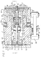
- Fig. 1 is an axial cross-sectional view of the embodiment of an electromagnetic linear compressor according to the invention.
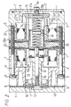
- Fig. 2 is a cross-section on the line A-A of Fig. 1.
- Fig. 3 is a cross-section on the line B-B of Fig. 1.
- Fig. 4 is an end view, partly sectioned, of the main body of the compressor of Fig. 1, with the cylinder head, head gasket and piston flap valve removed.
- Fig. 5 is an end view in the same direction as Fig. 4 with the head gasket and the piston flap valve in place.
- Fig. 6 is a partial section on line C-C of Fig. 5, with the cylinder head in place.
- Fig. 7 is a cross-section of a modified form of the cylinder head shown in Fig. 6.
- The compressor shown in the drawings has a body composed of a
main body 1 of square exterior cross-section transverse to the axis and arear body 2 secured together by bolts 4 (Fig. 2) withwashers 5. Thebodies cylinder head 3 is secured bybolts 3a (Fig. 6) in threadedholes 3b to themain body 1, with a one-piece sealinghead gasket 6 of thin flexible plastics material, in this instance Melanex ™, interposed between them. - The
rear body 2 has an annular recess housing afilter 7 for the air passing through the compressor, covered by anend plate 8 secured to the rear body by nut andbolt 8a or similar. - Axially reciprocatingly movable within the compressor is a
piston 10 with apiston head 11 located within acylinder 12 in thebody 1 and arear guide piston 13 slidably located in a piston guide 14 mounted in themain body 1 as described below. Thepiston head 11 has its peripherally outermost surface provided by an in situ mouldedcontinuous band 15 of plastics material, to minimize leakage of air past the piston. - Within the
main body 1 are electromagnetic drive coils 22 (Fig. 2) and between themain body 1 and therear body 2 there is astator 23 composed of a conventional stack of magnetically permeable laminations. Thepiston 10 carries anarmature 24 which is driven linearly by thecoils 22 and thestator 23, in a known manner, so that thepiston 10 is reciprocatingly driven by the linear motor thus constituted in one direction and by the restoring force of aspring arrangement 20 described below in the other direction. The reciprocation frequency is in accordance with the frequency of the applied AC voltage. The details of this driving arrangement need not be described further since it is well known. - Fig. 1 shows that the
cylinder surface 12a of thecylinder 12 is extended continuously rearwardly asinner surfaces 25a of two rearwardly projectingarms 25 of thebody 1, these arms projecting through thestator 23. Theinner surfaces 25a of thesearms 25 are thus part-cylindrical surfaces of the same diameter as thecylinder surface 12a, and are formed in the same machining operation as thecylinder surface 12a, so as to have a very high degree of concentricity and coaxiality with thecylinder surface 12a. A typical forming process for thesecylindrical surfaces body part 1, followed by anodizing of thesurfaces surfaces - The rear ends of the
surfaces 25a form registration surfaces for the exterior peripheralcylindrical surface 14a of the piston guide 14. This exteriorcylindrical surface 14a of the guide 14 is also highly accurately machined so as to form an accurate register fit within thesurfaces 25a, thus locating the piston guide 14 with a high degree of concentricity with thecylinder surface 12a. This achieves accurate radial location of the piston guide 14. The axial location of the piston guide 14, in abutment with thestator 23 is achieved in this embodiment by a resilientrubber compression body 27 and aspring support 19 to be described below located between the piston guide 14 and anopposed end wall 27a of therear body 2. Electrical isolation of the piston guide 14 from themain body 1 is achieved by the anodization of the mutually contactingsurfaces - The endmost one 23a of the laminations of the
stator 23, which is abutted by the piston guide 14, is not a metal lamination but is a sheet of an electrically insulating material, such as a plastics material, in order to electrically isolate the piston guide 14 from thestator 23. The abutment of the piston guide 14 with this endmost lamination of the stator axially locates the piston guide 14. The piston guide 14 is thus resiliently clamped against therigid stator 23 by theend wall 27a, through theresilient body 27. - As mentioned above, the
piston head 11 has an in situ mouldedcontinuous band 15 of low-friction plastics material acting as a piston ring. Theguide piston 13 also has around its periphery an in situ mouldedcontinuous band 13a of plastics material acting as a slide surface for theguide piston 13 on the piston guide 14. There may be recesses, in which thesebands guide piston 13 and thepiston head 11 respectively, since such screwthreads provide good keying for the plastics material and are easily formed. The low-friction plastics material used for thebands piston head 11 and theguide piston 13 are conveniently made. The difference of coefficient of thermal expansion between the piston head or guide piston and the material of thepiston ring bands - It can be seen in Figs. 1 and 2 that the portions of the piston guide 14 which do not contact the
surfaces 25a of thebody projections 25 are thinner walled, in order to avoid thecoils 22. - The
piston 10 is in several parts, secured together by abolt 16. Thebolt 16 passes through theguide piston 13 and thearmature 24 and is screwthreadedly engaged in aspacer part 17. After thepart 17 has been tightly threaded onto thebolt 16, thepiston head 11 is also tightly screwthreadedly attached to thebolt 16. Finally, after location of aflap valve 31 on the piston face, anut 70 is secured on thebolt 16 to hold theflap 31 in place. - Fig. 3 shows an air inlet passage 50 in the
rear body part 2 having in it a flow-control valve body 51, which is screwthreadedly engaged with ascrewthread 52 in the wall of the passage 50 and is thus adjustable in position along thisscrewthread 52. An air passage 53 allows the air to pass through thevalve body 51, and the flow of air into the compressor is controlled by the positioning of a conical leading end 54 of thevalve body 51 relative to anopposed shoulder 50a of the passage 50. Aspring 55 acts on thevalve body 51 to prevent its accidental rotation due for example to vibration. - The passage 50 leads to the outside surface of the
filter 7. Air passing through thefilter 7 goes into a small gap 56 (Fig. 1) between theend plate 8 and therear body 2, and then viapassages 57 in therear body 2 to inside the compressor, where it flows over thecoils 22 to cool them in order to reach the back face of thepiston head 11. This tortuous inlet path for the air helps to reduce noise emitted by the compressor. - Fig. 4 shows that the
piston head 11 has four apertures 30 (not shown in Figs. 1 and 2) through it, which are covered at the head face of thepiston head 11 by the flexible flap 31 (Fig. 1) to form a conventional flap valve, for admission of air from within the body of the compressor to the cylinder space in front of the piston on the reverse stroke of the piston. Theseapertures 30 in thepiston head 11 are angled with respect to the axis of the piston. The axis of eachaperture 30 is preferably about 30° to the axis of the compressor. A suitable range for this angle is 10° to 45°. The effect of this angling of theapertures 30 is that the air, moving rapidly through these apertures during the return stroke of the piston, applies a unidirectional rotational driving force on the piston by a turbine-like effect, rotating it slightly about its axis. This continual gradual unidirectional rotation about the axis minimizes the unevenness of any wear on the piston and cylinder surfaces of the compressor, i. e. renders such wear as uniform as possible. In combination with the lack of deflection forces and torsional forces from thespring system 20 described below, a predetermined and desired gradual rotation of the piston, due to this turbine effect of the air in theapertures 30, can be achieved. Since the torsional and deflection effects of the springs can be ignored, the desired rotational effect on the piston by the turbine effect is reproducible, in mass production of the compressor. In the present embodiment, a rotational speed of the piston of about 30 rpm has been achieved (the piston reciprocates at 50 Hz). - Instead of the
holes 30 on oblique axes, stepped holes (i.e. holes having portions circumferentially stepped around the piston axis) may be used, to achieve the effect of oblique air flow through the piston which causes its rotation. - Turning now to the
compression spring arrangement 20 shown in Figs. 1 and 2 this has twohelical springs rotational bearing 40 mounted between their mutually opposed ends. Thebearing 40 is supported only by thesprings springs friction washers 42 on which the ends of thesprings bearing 40 and are made of moulded PPS containing a lubricating medium and reinforcing fibre. The outer ends of thesprings spring support 19 andaxial projection 44 of theguide piston 13. - The
rotational bearing 40 is freely movable radially and axially, so that it provides no constraint against any flexing of the spring system. It allows free relative rotational movement of the inner ends of thesprings piston 10. The opposite coiling senses of the twosprings - The
spring support 19 is radially located relative to the piston guide 14 by ashoulder 19b which makes a register fit with the rear end of the piston guide 14. - Fig. 1 shows a mounting
bracket 60 of the compressor andelectrical leads 61, these parts being omitted from the other drawings, for simplicity. - The cylinder outlet valve and air flow arrangements at the cylinder head end will now be described.
- Figs. 1, 2 and 4 show that the
cylinder body 1 has in it at its forward end face eightdeep recesses 62 which are arranged in pairs, the two members of each pair being joined in each case by one of fourshallower recesses 63 in the body end face. One of theseshallower recesses 63 is in communication with theoutlet 64 of the compressor. In order to provide communication between these respective groups ofrecesses cylinder head 3 has fourrecesses 65 in its face opposing themain body 1. Therecesses 65 have sloping or bevelled rear faces 66 (two of these recesses can be seen in Fig. 6). Each of theserecesses 65 is of a size so as to provide communication between two adjacent non-communicatingdeep recesses 62 of themain body 1. Thus around the head end of the cylinder there is a continuous gallery for movement of air, provided by therecesses - The gallery just described communicates with the interior of the
cylinder 12 via apassage 67 opening in a side wall of thecylinder 12 and terminating at anoutlet end 68 in the end face of thebody 1, at a location corresponding to one of therecesses 65 of thecylinder head 3. As Fig. 5 shows, thehead gasket 6 lying between thecylinder head 3 and themain body 1, which seals around the head end of thecylinder 12, has four inwardly directedintegral flap portions 69 one of which covers the outlet end 68 of thepassage 67 thus forming a flap valve permitting flow of the compressed air out of thecylinder 12 but preventing reverse flow into the cylinder through thepassage 67. Thisflap portion 69 moves within therecess 65 of thecylinder head 3 between its closed and open positions, and the length of its travel between these positions is determined by the angle of the bevelrear face 66 of therecess 65. - It can be seen from Fig. 5 that the
gasket 6 can be mounted in any one of four different positions angularly spaced by 90°, in each of which one of theintegral flap portions 69 constitutes the flap valve controlling the flow of air in thepassage 67. Likewise thecylinder head 3 can also be secured to thebody 1 in any one of four positions, also angularly spaced by 90°. The fourdifferent recesses 65 of thecylinder head 3 have respectively different bevel angles of the bevelled rear faces 66. Consequently, the characteristic of the flap valve arrangement at the outlet of thepassage 67 is different for each of the four positions of the cylinder head, because the travel of thevalve member 69 is different and also the volume of therecess 65 is different in each case. - Furthermore, in the modification shown in Fig. 7, the
cylinder head 3 is reversible so that either of its main faces can face towards themain body 1 of the compressor. For this purpose it has four of therecesses 65 on each of its two main faces and it also has two differentcentral recesses 71, so that the effective volume of thecylinder 12 at its head end is different, depending on which of the two reverse positions of thecylinder head 3 is chosen. This again allows some adjustment of the characteristics of the compressor. Fig. 7 also shows different bevel angles of the rear faces of therecesses 65. - These possibilities for adjustment of the characteristics of the compressor allow it to be adapted according to a particular use, depending on the relationship of the volume of air flow and the pressure of the emitted air.
- It can be seen from Fig. 6 that when the
piston head 11 approaches the limit of its travel towards thecylinder head 3, itsring band 15 closes theoutlet passage 67. This means that during the final portion of the travel of the piston, air is compressed between the piston head and the cylinder head, which causes the piston to stop before it hits the cylinder head. Since theband 15 is a one-piece moulded construction and is continuous around thepiston head 11, there is no leakage path between the space in front of the piston and thepassage 67, in any rotational position of the piston, after theband 15 has come alongside thepassage 67.
Claims (4)
- An electromagnetic reciprocating compressor having a piston (10) reciprocating in a cylinder (12), a body (1,2) providing said cylinder, electromagnetic drive means (22,23) in said body for driving said piston reciprocatingly including a stator (23), and a piston guide (14) in the form of an insert axially and radially located relative to said cylinder (12), characterised in that said piston guide (14) is axially located relative to said cylinder (12) by being resiliently clamped between said stator (23) and an end portion (27a) of said body (1,2) opposed to said stator (23) with a resilient member (27) interposed between said body end portion (27a) and said piston guide (14).
- A compressor according to claim 1 wherein said resilient member (27) is electrically insulating.
- A compressor according to claim 1 or claim 2 wherein an electrically insulating member (23a) is interposed between said stator (23) and said piston guide (14).
- A compressor according to claim 3 wherein said stator (23) comprises a stack comprised of magnetically permeable laminations and said electrically insulating member (23a) is a sheet located at one end of said stack.
Applications Claiming Priority (3)
| Application Number | Priority Date | Filing Date | Title |
|---|---|---|---|
| GB9311385 | 1993-06-02 | ||
| GB939311385A GB9311385D0 (en) | 1993-06-02 | 1993-06-02 | Compressor |
| EP94916348A EP0706613B1 (en) | 1993-06-02 | 1994-06-02 | Compressor |
Related Parent Applications (2)
| Application Number | Title | Priority Date | Filing Date |
|---|---|---|---|
| EP94916348A Division EP0706613B1 (en) | 1993-06-02 | 1994-06-02 | Compressor |
| EP94916348.9 Division | 1994-12-08 |
Publications (3)
| Publication Number | Publication Date |
|---|---|
| EP0770779A2 true EP0770779A2 (en) | 1997-05-02 |
| EP0770779A3 EP0770779A3 (en) | 1997-05-21 |
| EP0770779B1 EP0770779B1 (en) | 1998-09-23 |
Family
ID=10736510
Family Applications (4)
| Application Number | Title | Priority Date | Filing Date |
|---|---|---|---|
| EP97109425A Expired - Lifetime EP0796995B1 (en) | 1993-06-02 | 1994-06-02 | Compressor |
| EP94916348A Expired - Lifetime EP0706613B1 (en) | 1993-06-02 | 1994-06-02 | Compressor |
| EP94916346A Expired - Lifetime EP0704023B1 (en) | 1993-06-02 | 1994-06-02 | Compressor |
| EP97100165A Expired - Lifetime EP0770779B1 (en) | 1993-06-02 | 1994-06-02 | Compressor |
Family Applications Before (3)
| Application Number | Title | Priority Date | Filing Date |
|---|---|---|---|
| EP97109425A Expired - Lifetime EP0796995B1 (en) | 1993-06-02 | 1994-06-02 | Compressor |
| EP94916348A Expired - Lifetime EP0706613B1 (en) | 1993-06-02 | 1994-06-02 | Compressor |
| EP94916346A Expired - Lifetime EP0704023B1 (en) | 1993-06-02 | 1994-06-02 | Compressor |
Country Status (9)
| Country | Link |
|---|---|
| US (3) | US5597294A (en) |
| EP (4) | EP0796995B1 (en) |
| JP (2) | JPH08510526A (en) |
| AT (4) | ATE157430T1 (en) |
| AU (3) | AU6803994A (en) |
| DE (4) | DE69413038T2 (en) |
| DK (1) | DK0706613T3 (en) |
| GB (2) | GB9311385D0 (en) |
| WO (3) | WO1994028306A1 (en) |
Cited By (2)
| Publication number | Priority date | Publication date | Assignee | Title |
|---|---|---|---|---|
| WO2001069084A1 (en) * | 2000-03-11 | 2001-09-20 | Archfact Limited | Compressor spring locator |
| GB2424678A (en) * | 2005-03-28 | 2006-10-04 | Nitto Kohki Co | electromagnetic reciprocating fluid apparatus |
Families Citing this family (29)
| Publication number | Priority date | Publication date | Assignee | Title |
|---|---|---|---|---|
| GB9311385D0 (en) * | 1993-06-02 | 1993-07-21 | Contech Int Ltd | Compressor |
| GB9424790D0 (en) * | 1994-12-08 | 1995-02-08 | Pegasus Airwave Ltd | Compressor |
| KR100224186B1 (en) * | 1996-01-16 | 1999-10-15 | 윤종용 | Linear compressorr |
| WO1998001675A1 (en) * | 1996-07-09 | 1998-01-15 | Sanyo Electric Co., Ltd. | Linear compressor |
| GB2312835B (en) * | 1996-12-18 | 1998-08-12 | Pegasus Airwave Ltd | Patient supports and methods of operating them |
| US6273688B1 (en) * | 1998-10-13 | 2001-08-14 | Matsushita Electric Industrial Co., Ltd. | Linear compressor |
| US6129527A (en) * | 1999-04-16 | 2000-10-10 | Litton Systems, Inc. | Electrically operated linear motor with integrated flexure spring and circuit for use in reciprocating compressor |
| JP2001227461A (en) * | 2000-02-14 | 2001-08-24 | Matsushita Electric Ind Co Ltd | Linear compressor |
| TW504546B (en) * | 2000-10-17 | 2002-10-01 | Fisher & Amp Paykel Ltd | A linear compressor |
| GB0117834D0 (en) * | 2001-07-21 | 2001-09-12 | Archfact Ltd | Gasket |
| KR100548270B1 (en) * | 2003-04-18 | 2006-02-02 | 엘지전자 주식회사 | Fixing structure of stater for liner compressor |
| NZ526361A (en) * | 2003-05-30 | 2006-02-24 | Fisher & Paykel Appliances Ltd | Compressor improvements |
| US7777600B2 (en) * | 2004-05-20 | 2010-08-17 | Powerpath Technologies Llc | Eddy current inductive drive electromechanical liner actuator and switching arrangement |
| US20090263262A1 (en) * | 2004-11-02 | 2009-10-22 | Mcgill Ian Campbell | Linear Compressor |
| JP4520834B2 (en) * | 2004-11-26 | 2010-08-11 | 日東工器株式会社 | Electromagnetic reciprocating fluid device |
| WO2009120670A1 (en) * | 2008-03-26 | 2009-10-01 | Pollack Robert W | Systems and methods for energizing and distributing fluids |
| DE102004062300A1 (en) * | 2004-12-23 | 2006-07-13 | BSH Bosch und Siemens Hausgeräte GmbH | linear compressor |
| DE102009001315A1 (en) | 2009-03-04 | 2010-09-09 | Robert Bosch Gmbh | Piston pump for use as high-pressure pump for internal-combustion engine in motor vehicle, has piston displacable in cylinder by cam shaft against force of coil spring, where coil spring has winding direction opposite to another coil spring |
| US9856866B2 (en) | 2011-01-28 | 2018-01-02 | Wabtec Holding Corp. | Oil-free air compressor for rail vehicles |
| BRPI1103647A2 (en) * | 2011-07-07 | 2013-07-02 | Whirlpool Sa | arrangement between linear compressor components |
| BRPI1103447A2 (en) * | 2011-07-19 | 2013-07-09 | Whirlpool Sa | spring bundle for compressor and spring bundled compressor |
| BRPI1104172A2 (en) * | 2011-08-31 | 2015-10-13 | Whirlpool Sa | linear compressor based on resonant oscillating mechanism |
| CN104329238B (en) * | 2013-07-22 | 2018-01-09 | 青岛海尔智能技术研发有限公司 | The piston of linear compressor and linear compressor |
| US9429150B2 (en) * | 2014-02-10 | 2016-08-30 | Haier US Appliances Solutions, Inc. | Linear compressor |
| US9322401B2 (en) * | 2014-02-10 | 2016-04-26 | General Electric Company | Linear compressor |
| US9506460B2 (en) * | 2014-02-10 | 2016-11-29 | Haier Us Appliance Solutions, Inc. | Linear compressor |
| US9518572B2 (en) * | 2014-02-10 | 2016-12-13 | Haier Us Appliance Solutions, Inc. | Linear compressor |
| JP6353771B2 (en) * | 2014-11-25 | 2018-07-04 | 株式会社日立製作所 | Linear motor and compressor equipped with linear motor |
| KR102238339B1 (en) * | 2016-05-03 | 2021-04-09 | 엘지전자 주식회사 | linear compressor |
Citations (6)
| Publication number | Priority date | Publication date | Assignee | Title |
|---|---|---|---|---|
| US4090816A (en) | 1975-10-14 | 1978-05-23 | Man Design Co., Ltd. | Electromagnetic fluid operating apparatus |
| GB2041092A (en) | 1979-02-08 | 1980-09-03 | Man Design Co | Electro-magnetic fluid pump |
| US4718832A (en) | 1985-03-11 | 1988-01-12 | Man Design Co., Ltd. | Electromagnetic reciprocating pump |
| GB2206931A (en) | 1987-06-17 | 1989-01-18 | Nitto Kohki Co | Electromagnetically reciprocating apparatus |
| US4867656A (en) | 1987-05-30 | 1989-09-19 | Nitto Kohki Co., Ltd. | Free piston for use in an electromagnetic reciprocating compressor |
| US5100304A (en) | 1990-05-09 | 1992-03-31 | Nitto Kohki Co., Ltd. | Solenoid-operated reciprocating pump |
Family Cites Families (22)
| Publication number | Priority date | Publication date | Assignee | Title |
|---|---|---|---|---|
| FR1013829A (en) * | 1950-03-04 | 1952-08-05 | Rotary groove piston | |
| AT194870B (en) * | 1955-12-07 | 1958-01-25 | Licentia Gmbh | Electromagnetic vibration compressor, preferably for refrigeration machines |
| SE355215B (en) * | 1971-03-17 | 1973-04-09 | Atlas Copco Ab | |
| DE2122939A1 (en) * | 1971-05-10 | 1972-11-23 | Mikuni Jukogyo K.K., Osaka (Japan) | Lubricant-free piston with piston ring for a gas compressor |
| FR2158583A6 (en) * | 1971-08-31 | 1973-06-15 | Barthalon Maurice | |
| CH549896A (en) * | 1972-09-22 | 1974-05-31 | Landis & Gyr Ag | ROCKER - PISTON PUMP. |
| JPS51116411A (en) * | 1975-04-04 | 1976-10-13 | Man Design Kk | An enclosed-type electromagnetic-starting compressor electromagnetic-s tarting compressor |
| LU73529A1 (en) * | 1975-10-06 | 1977-07-15 | ||
| US4067093A (en) * | 1976-05-24 | 1978-01-10 | Dynamic Seals Incorporated | Piston assembly and method for manufacturing |
| US4357915A (en) * | 1980-11-12 | 1982-11-09 | Monsour James R | Propeller and piston combination for internal combustion engines |
| JPS57149657A (en) * | 1981-03-12 | 1982-09-16 | Sumitomo Bakelite Co Ltd | High precison piston and its manufacturing method |
| JPS57176343A (en) * | 1981-04-21 | 1982-10-29 | Isao Matsui | Piston |
| JPS5987285A (en) * | 1982-11-12 | 1984-05-19 | Man Design Kk | Electromagnetic reciprocating compressor |
| SU1460406A1 (en) * | 1985-01-04 | 1989-02-23 | Омский политехнический институт | Electromagnetic compressor |
| NL8503037A (en) * | 1985-11-06 | 1987-06-01 | Philips Nv | DEVICE WITH A HYDRODYNAMICALLY BEARING PISTON. |
| US4815948A (en) * | 1985-11-21 | 1989-03-28 | Pastore Aurelio | Vibratory pump |
| US4721440A (en) * | 1987-02-13 | 1988-01-26 | Mechanical Technology Incorporated | Linear gas compressor |
| US4966533A (en) * | 1987-07-14 | 1990-10-30 | Kabushiki Kaisha Nagano Keiki Seisakusho | Vacuum pump with rotational sliding piston support |
| US4776776A (en) * | 1987-08-24 | 1988-10-11 | The Devilbiss Company | Small pump valve plate assembly |
| JPH03253776A (en) * | 1990-03-05 | 1991-11-12 | Nitto Kohki Co Ltd | Electromagnetic reciprocating pump |
| JPH04121477U (en) * | 1991-04-16 | 1992-10-29 | サンデン株式会社 | Free piston type compressor |
| GB9311385D0 (en) * | 1993-06-02 | 1993-07-21 | Contech Int Ltd | Compressor |
-
1993
- 1993-06-02 GB GB939311385A patent/GB9311385D0/en active Pending
-
1994
- 1994-06-02 JP JP7500429A patent/JPH08510526A/en active Pending
- 1994-06-02 AT AT94916348T patent/ATE157430T1/en not_active IP Right Cessation
- 1994-06-02 DE DE69413038T patent/DE69413038T2/en not_active Expired - Fee Related
- 1994-06-02 EP EP97109425A patent/EP0796995B1/en not_active Expired - Lifetime
- 1994-06-02 JP JP7500431A patent/JPH08510527A/en active Pending
- 1994-06-02 AU AU68039/94A patent/AU6803994A/en not_active Abandoned
- 1994-06-02 WO PCT/GB1994/001193 patent/WO1994028306A1/en active IP Right Grant
- 1994-06-02 GB GB9524175A patent/GB2294297B/en not_active Expired - Fee Related
- 1994-06-02 EP EP94916348A patent/EP0706613B1/en not_active Expired - Lifetime
- 1994-06-02 AT AT97100165T patent/ATE171515T1/en not_active IP Right Cessation
- 1994-06-02 US US08/556,901 patent/US5597294A/en not_active Expired - Fee Related
- 1994-06-02 EP EP94916346A patent/EP0704023B1/en not_active Expired - Lifetime
- 1994-06-02 AT AT94916346T patent/ATE170598T1/en not_active IP Right Cessation
- 1994-06-02 AU AU68040/94A patent/AU6804094A/en not_active Abandoned
- 1994-06-02 DE DE69413565T patent/DE69413565T2/en not_active Expired - Fee Related
- 1994-06-02 AT AT97109425T patent/ATE170263T1/en not_active IP Right Cessation
- 1994-06-02 EP EP97100165A patent/EP0770779B1/en not_active Expired - Lifetime
- 1994-06-02 DE DE69405239T patent/DE69405239T2/en not_active Expired - Fee Related
- 1994-06-02 WO PCT/GB1994/001195 patent/WO1994028308A1/en active IP Right Grant
- 1994-06-02 DE DE69412869T patent/DE69412869T2/en not_active Expired - Fee Related
- 1994-06-02 AU AU68038/94A patent/AU6803894A/en not_active Abandoned
- 1994-06-02 WO PCT/GB1994/001194 patent/WO1994028307A1/en active Application Filing
- 1994-06-02 US US08/556,903 patent/US5603612A/en not_active Expired - Fee Related
- 1994-06-02 DK DK94916348.9T patent/DK0706613T3/en active
-
1997
- 1997-01-29 US US08/790,486 patent/US5727932A/en not_active Expired - Fee Related
Patent Citations (7)
| Publication number | Priority date | Publication date | Assignee | Title |
|---|---|---|---|---|
| US4090816A (en) | 1975-10-14 | 1978-05-23 | Man Design Co., Ltd. | Electromagnetic fluid operating apparatus |
| GB1529597A (en) | 1975-10-14 | 1978-10-25 | Man Design Co | Electromagnetic gas pump |
| GB2041092A (en) | 1979-02-08 | 1980-09-03 | Man Design Co | Electro-magnetic fluid pump |
| US4718832A (en) | 1985-03-11 | 1988-01-12 | Man Design Co., Ltd. | Electromagnetic reciprocating pump |
| US4867656A (en) | 1987-05-30 | 1989-09-19 | Nitto Kohki Co., Ltd. | Free piston for use in an electromagnetic reciprocating compressor |
| GB2206931A (en) | 1987-06-17 | 1989-01-18 | Nitto Kohki Co | Electromagnetically reciprocating apparatus |
| US5100304A (en) | 1990-05-09 | 1992-03-31 | Nitto Kohki Co., Ltd. | Solenoid-operated reciprocating pump |
Cited By (5)
| Publication number | Priority date | Publication date | Assignee | Title |
|---|---|---|---|---|
| WO2001069084A1 (en) * | 2000-03-11 | 2001-09-20 | Archfact Limited | Compressor spring locator |
| US7008195B2 (en) | 2000-03-11 | 2006-03-07 | Archfact Limited | Compressor spring locator |
| GB2424678A (en) * | 2005-03-28 | 2006-10-04 | Nitto Kohki Co | electromagnetic reciprocating fluid apparatus |
| GB2424678B (en) * | 2005-03-28 | 2007-09-12 | Nitto Kohki Co | Electromagnetic reciprocating fluid apparatus |
| US7932647B2 (en) | 2005-03-28 | 2011-04-26 | Nitto Kohki Co., Ltd. | Electromagnetic reciprocating fluid apparatus |
Also Published As
Similar Documents
| Publication | Publication Date | Title |
|---|---|---|
| EP0706613B1 (en) | Compressor | |
| US6326706B1 (en) | Linear motor compressor | |
| JP4690018B2 (en) | Wear prevention device for reciprocating compressor | |
| US20070041856A1 (en) | Linear compressor | |
| KR940008439Y1 (en) | Electromagnetically driven pump | |
| EP0509660A1 (en) | Free piston-type compressor | |
| US6024542A (en) | Piston pump and method of reducing vapor lock | |
| US5395218A (en) | Fluid pump apparatus | |
| EP0796395B1 (en) | Compressor | |
| US5076537A (en) | Electromechanical servovalve | |
| GB2303887A (en) | Electromagnetic reciprocating compressor | |
| GB2303886A (en) | Electromagnetic reciprocating compressor | |
| US11808256B2 (en) | Compressor including discharge plenum | |
| CN110285224B (en) | Electronic flow regulating valve | |
| US20070041854A1 (en) | Linear compressor, particularly refrigerant compressor | |
| EP0494653A1 (en) | Low cost linear actuator | |
| JP3331489B2 (en) | Opposed piston compressor | |
| KR100273440B1 (en) | Linear compressor | |
| US11384836B2 (en) | Piston for compressor | |
| EP4273428A1 (en) | Electric valve | |
| CN213627895U (en) | Linear compressor with stable and reliable work | |
| US20190360474A1 (en) | Motor pump | |
| JPH0419384A (en) | Fluid pressure compressor |
Legal Events
| Date | Code | Title | Description |
|---|---|---|---|
| PUAI | Public reference made under article 153(3) epc to a published international application that has entered the european phase |
Free format text: ORIGINAL CODE: 0009012 |
|
| PUAL | Search report despatched |
Free format text: ORIGINAL CODE: 0009013 |
|
| 17P | Request for examination filed |
Effective date: 19970127 |
|
| AC | Divisional application: reference to earlier application |
Ref document number: 706613 Country of ref document: EP |
|
| AK | Designated contracting states |
Kind code of ref document: A2 Designated state(s): AT BE DE FR IE IT NL |
|
| AK | Designated contracting states |
Kind code of ref document: A3 Designated state(s): AT BE DE FR IE IT NL |
|
| 17Q | First examination report despatched |
Effective date: 19970722 |
|
| GRAG | Despatch of communication of intention to grant |
Free format text: ORIGINAL CODE: EPIDOS AGRA |
|
| GRAG | Despatch of communication of intention to grant |
Free format text: ORIGINAL CODE: EPIDOS AGRA |
|
| GRAH | Despatch of communication of intention to grant a patent |
Free format text: ORIGINAL CODE: EPIDOS IGRA |
|
| GRAH | Despatch of communication of intention to grant a patent |
Free format text: ORIGINAL CODE: EPIDOS IGRA |
|
| GRAA | (expected) grant |
Free format text: ORIGINAL CODE: 0009210 |
|
| AC | Divisional application: reference to earlier application |
Ref document number: 706613 Country of ref document: EP |
|
| AK | Designated contracting states |
Kind code of ref document: B1 Designated state(s): AT BE DE FR IE IT NL |
|
| REF | Corresponds to: |
Ref document number: 171515 Country of ref document: AT Date of ref document: 19981015 Kind code of ref document: T |
|
| REF | Corresponds to: |
Ref document number: 69413565 Country of ref document: DE Date of ref document: 19981029 |
|
| REG | Reference to a national code |
Ref country code: IE Ref legal event code: FG4D |
|
| ET | Fr: translation filed | ||
| PLBE | No opposition filed within time limit |
Free format text: ORIGINAL CODE: 0009261 |
|
| STAA | Information on the status of an ep patent application or granted ep patent |
Free format text: STATUS: NO OPPOSITION FILED WITHIN TIME LIMIT |
|
| 26N | No opposition filed | ||
| PGFP | Annual fee paid to national office [announced via postgrant information from national office to epo] |
Ref country code: FR Payment date: 20020624 Year of fee payment: 9 |
|
| PGFP | Annual fee paid to national office [announced via postgrant information from national office to epo] |
Ref country code: IE Payment date: 20020625 Year of fee payment: 9 Ref country code: AT Payment date: 20020625 Year of fee payment: 9 |
|
| PGFP | Annual fee paid to national office [announced via postgrant information from national office to epo] |
Ref country code: BE Payment date: 20020626 Year of fee payment: 9 |
|
| PGFP | Annual fee paid to national office [announced via postgrant information from national office to epo] |
Ref country code: NL Payment date: 20020628 Year of fee payment: 9 |
|
| PGFP | Annual fee paid to national office [announced via postgrant information from national office to epo] |
Ref country code: DE Payment date: 20020629 Year of fee payment: 9 |
|
| PG25 | Lapsed in a contracting state [announced via postgrant information from national office to epo] |
Ref country code: IE Free format text: LAPSE BECAUSE OF NON-PAYMENT OF DUE FEES Effective date: 20030602 Ref country code: AT Free format text: LAPSE BECAUSE OF NON-PAYMENT OF DUE FEES Effective date: 20030602 |
|
| PG25 | Lapsed in a contracting state [announced via postgrant information from national office to epo] |
Ref country code: BE Free format text: LAPSE BECAUSE OF NON-PAYMENT OF DUE FEES Effective date: 20030630 |
|
| BERE | Be: lapsed |
Owner name: *PEGASUS AIRWAVE LTD Effective date: 20030630 |
|
| PG25 | Lapsed in a contracting state [announced via postgrant information from national office to epo] |
Ref country code: NL Free format text: LAPSE BECAUSE OF NON-PAYMENT OF DUE FEES Effective date: 20040101 Ref country code: DE Free format text: LAPSE BECAUSE OF NON-PAYMENT OF DUE FEES Effective date: 20040101 |
|
| PG25 | Lapsed in a contracting state [announced via postgrant information from national office to epo] |
Ref country code: FR Free format text: LAPSE BECAUSE OF NON-PAYMENT OF DUE FEES Effective date: 20040227 |
|
| NLV4 | Nl: lapsed or anulled due to non-payment of the annual fee |
Effective date: 20040101 |
|
| REG | Reference to a national code |
Ref country code: FR Ref legal event code: ST |
|
| REG | Reference to a national code |
Ref country code: IE Ref legal event code: MM4A |
|
| PG25 | Lapsed in a contracting state [announced via postgrant information from national office to epo] |
Ref country code: IT Free format text: LAPSE BECAUSE OF NON-PAYMENT OF DUE FEES;WARNING: LAPSES OF ITALIAN PATENTS WITH EFFECTIVE DATE BEFORE 2007 MAY HAVE OCCURRED AT ANY TIME BEFORE 2007. THE CORRECT EFFECTIVE DATE MAY BE DIFFERENT FROM THE ONE RECORDED. Effective date: 20050602 |