EP0770985A2 - Signal encoding method and apparatus - Google Patents
Signal encoding method and apparatus Download PDFInfo
- Publication number
- EP0770985A2 EP0770985A2 EP96307742A EP96307742A EP0770985A2 EP 0770985 A2 EP0770985 A2 EP 0770985A2 EP 96307742 A EP96307742 A EP 96307742A EP 96307742 A EP96307742 A EP 96307742A EP 0770985 A2 EP0770985 A2 EP 0770985A2
- Authority
- EP
- European Patent Office
- Prior art keywords
- signal
- encoding
- pitch
- band
- circuit
- Prior art date
- Legal status (The legal status is an assumption and is not a legal conclusion. Google has not performed a legal analysis and makes no representation as to the accuracy of the status listed.)
- Granted
Links
Images


Classifications
-
- G—PHYSICS
- G10—MUSICAL INSTRUMENTS; ACOUSTICS
- G10L—SPEECH ANALYSIS OR SYNTHESIS; SPEECH RECOGNITION; SPEECH OR VOICE PROCESSING; SPEECH OR AUDIO CODING OR DECODING
- G10L19/00—Speech or audio signals analysis-synthesis techniques for redundancy reduction, e.g. in vocoders; Coding or decoding of speech or audio signals, using source filter models or psychoacoustic analysis
- G10L19/02—Speech or audio signals analysis-synthesis techniques for redundancy reduction, e.g. in vocoders; Coding or decoding of speech or audio signals, using source filter models or psychoacoustic analysis using spectral analysis, e.g. transform vocoders or subband vocoders
- G10L19/0212—Speech or audio signals analysis-synthesis techniques for redundancy reduction, e.g. in vocoders; Coding or decoding of speech or audio signals, using source filter models or psychoacoustic analysis using spectral analysis, e.g. transform vocoders or subband vocoders using orthogonal transformation
-
- G—PHYSICS
- G10—MUSICAL INSTRUMENTS; ACOUSTICS
- G10L—SPEECH ANALYSIS OR SYNTHESIS; SPEECH RECOGNITION; SPEECH OR VOICE PROCESSING; SPEECH OR AUDIO CODING OR DECODING
- G10L19/00—Speech or audio signals analysis-synthesis techniques for redundancy reduction, e.g. in vocoders; Coding or decoding of speech or audio signals, using source filter models or psychoacoustic analysis
- G10L19/02—Speech or audio signals analysis-synthesis techniques for redundancy reduction, e.g. in vocoders; Coding or decoding of speech or audio signals, using source filter models or psychoacoustic analysis using spectral analysis, e.g. transform vocoders or subband vocoders
- G10L19/0204—Speech or audio signals analysis-synthesis techniques for redundancy reduction, e.g. in vocoders; Coding or decoding of speech or audio signals, using source filter models or psychoacoustic analysis using spectral analysis, e.g. transform vocoders or subband vocoders using subband decomposition
- G10L19/0208—Subband vocoders
-
- G—PHYSICS
- G10—MUSICAL INSTRUMENTS; ACOUSTICS
- G10L—SPEECH ANALYSIS OR SYNTHESIS; SPEECH RECOGNITION; SPEECH OR VOICE PROCESSING; SPEECH OR AUDIO CODING OR DECODING
- G10L19/00—Speech or audio signals analysis-synthesis techniques for redundancy reduction, e.g. in vocoders; Coding or decoding of speech or audio signals, using source filter models or psychoacoustic analysis
- G10L19/04—Speech or audio signals analysis-synthesis techniques for redundancy reduction, e.g. in vocoders; Coding or decoding of speech or audio signals, using source filter models or psychoacoustic analysis using predictive techniques
- G10L19/06—Determination or coding of the spectral characteristics, e.g. of the short-term prediction coefficients
- G10L19/07—Line spectrum pair [LSP] vocoders
Definitions
- This invention relates to a method and apparatus for encoding an input signal, such as a broad-range speech signal. More particularly, it relates to a signal encoding method and apparatus in which the frequency spectrum is split into a telephone band for which sufficient clarity as speech can be obtained and the remaining band and in which signal encoding can be realized by an independent codec as long as the telephone band is concerned.
- the encoding methods may be roughly classified into encoding on the time axis, encoding on the frequency axis and analysis synthesis encoding.
- harmonic encoding a sinusoidal analytic encoding
- MBE multi-band excitation
- SBC sub-band encoding
- LPC linear predictive coding
- DCT discrete cosine transform
- MDCT modified DCT
- FFT fast Fourier transform
- bitstream itself has scalability such that a bitstream having a high bit rate is received and, if the bitstream is decoded directly, high-quality signals are produced, whereas, if a specified portion of the bitstream is decoded, signal of low sound quality are produced.
- a signal to be processed is roughly quantized on the encoding side to produce a bitstream with a low bit rate.
- the quantization error produced on quantization is further quantized and added to the bitstream of the low bit rate to produce a high bit rate bitstream.
- the bitstream can have scalability as described above, that is, a high-quality signal can be obtained by directly decoding the high bit rate bitstream, while a low bit rate signal can be reproduced by taking out and decoding a portion of the bitstream.
- waveform encoding is preferably performed with a high bit rate. If waveform encoding cannot be achieved smoothly, encoding has to be performed using a model for a low bit rate.
- the above inclusive relation in which the high bit rate includes the low bit rate cannot be achieved because of the difference in the information for encoding.
- a signal encoding method including a band-splitting step for splitting an input signal into plurality of bands and encoding signals of the bands in a different manner depending on signal characteristics of the bands.
- the present invention provides a method and apparatus for multiplexing an encoded signal having speech encoding means in turn having means for multiplexing a first encoded signal obtained on first encoding of an input signal employing a first bit rate and a second encoded signal obtained on second encoding of the input signal and means for multiplexing the first encoded signal and a portion of the second encoded signal excluding the portion thereof owned in common by the first encoded signal.
- the second encoding has a portion in common with only a portion of the first encoding and a portion not in common with the first encoding.
- the second encoding employs a second bit rate different from the bit rate for the first encoding.
- the input signal is split into plural bands and signals of the bands thus split are encoded in a different manner depending on signal characteristics of the split bands.
- a decoder operation with different rates is enabled and encoding may be performed with an optimum efficiency for each band thus improving the encoding efficiency.
- At least a band of the input signal is taken out, and the signal of the band thus taken out is orthogonal-transformed into a frequency-domain signal.
- the orthogonal-transformed signal is shifted on the frequency axis to another position or band and subsequently inverse orthogonal-transformed to time-domain signals, which are encoded.
- the signal of an arbitrary frequency band is taken out and converted into a low-range side for encoding with a low sampling frequency.
- a sub-band of an arbitrary frequency width may be produced from an arbitrary frequency so as to be processed with a sampling frequency twice the frequency width thus enabling an application to be dealt with flexibly.
- Fig. 1 is a block diagram showing a basic structure of a speech signal encoding apparatus for carrying out the encoding method embodying the present invention.
- Fig.2 is a block diagram for illustrating the basic structure of a speech signal decoding apparatus.
- Fig.3 is a block diagram for illustrating the structure of another speech signal encoding apparatus.
- Fig.4 illustrates scalability of a bitstream of transmitted encoded data.
- Fig.5 is a schematic block diagram showing the entire system of the encoding side according to the present invention.
- Figs.6A, 6B and 6C illustrate the period and the phase of main operations for encoding and decoding.
- Figs.7A and 7B illustrate vector quantization of MDCT coefficients.
- Figs.8A and 8B illustrate examples of windowing functions applied to a post-filter output.
- Fig.9 shows an illustrative vector quantization device having two sorts of codebooks.
- Fig.10 is a block diagram showing a detailed structure of a vector quantization apparatus having two sorts of codebooks.
- Fig. 11 is a block diagram showing another detailed structure of a vector quantization apparatus having two sorts of codebooks.
- Fig. 12 is a block diagram showing the structure of an encoder for frequency conversion.
- Figs. 13A, 13B illustrate frame splitting and overlap-and-add operations.
- Figs.14A, 14B and 14C illustrate an example of frequency shifting on the frequency axis.
- Figs. 15A and 15B illustrate data shifting on the frequency axis.
- Fig.16 is a block diagram showing the structure of a decoder for frequency conversion.
- Figs.17A, 17B and 17C illustrate another example of frequency shifting on the frequency axis.
- Fig. 18 is a block diagram showing the structure of a transmitting side of a portable terminal employing a speech encoding apparatus of the present invention.
- Fig. 19 is a block diagram showing the structure of a receiving side of a portable terminal employing a speech signal decoding apparatus associated with Fig.18.
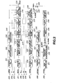
- Fig.1 shows an encoding apparatus (encoder) for broad-range speech signals for carrying out the speech encoding method according to the present invention.
- the basic concept of the encoder shown in Fig.1 is that the input signal is split into plural bands and the signals of the split bands are encoded in a different manner depending on signal characteristics of the respective bands.
- the frequency spectrum of the broad-range input speech signals is split into plural bands, namely the telephone band for which sufficient clarity as speech can be achieved, and a band on the higher side relative to the telephone band.
- the signals of the lower band, that is the telephone band are orthogonal-transformed after short-term prediction such as linear predictive coding (LPC) followed by long-term prediction, such as pitch prediction, and the coefficient obtained on orthogonal transform are processed with perceptually weighted vector quantization.
- LPC linear predictive coding
- the information concerning long-term prediction such as pitch or pitch gain, or parameters representing the short-term prediction coefficients, such as LPC coefficients, are also quantized.
- the signals of the band higher than the telephone band are processed with short-term prediction and then vector-quantized directly on the time axis.
- the modified DCT is used as the orthogonal transform.
- the conversion length is shortened for facilitating weighting for vector quantization.
- the conversion length is set to 2 N , that is to a value equal to powers of 2, for enabling high processing speed by employing fast Fourier transform (FFT).
- FFT fast Fourier transform
- the LPC coefficients for calculating the weighting for vector quantization of the orthogonal transform coefficients and for calculating the residuals for short-term prediction are the LPC coefficients smoothly interpolated from the LPC coefficients found in the current frame and those found in the past frame, so that the LPC coefficients used will be optimum for each sub-frame being analyzed.
- prediction or interpolation is carried out a number of times for each frame and the resulting pitch lag or pitch gain is quantized directly or after finding the difference. Alternatively, a flag specifying the method for interpolation is transmitted.
- multi-stage vector quantization is carried out for quantizing the difference of the orthogonal transform coefficients.
- only the parameters for a sole band among the split bands are used for enabling plural decoding operations with different bit rates by all or part of a sole encoded bitstream.
- broad-band speech signals in a range of, for example, from 0 to 8 kHz with a sampling frequency Fs of, for example, 16 kHz.
- the broad-band speech signals from the input terminal 101 are split by a low-pass filter 102 and a subtractor 106 into low-range telephone band signals of, for example, 0 to 3.8 kHz, and high-range signals, such as signals in a range of, for example, from 3.8 kHz to 8 kHz.
- the low-range signals are decimated by a sampling frequency converter 103 in a range satisfying the sampling theorem to provide e.g., 8 kHz-sampling signals.
- the low-range signals are multiplied by an LPC analysis quantization unit 130 by a Hamming window with an analysis length on the order of, for example, 256 samples per block.
- the LPC coefficients of, for example, 10 order, that is ⁇ -parameters, are found, and LPC residuals are found by an LPC inverted filter 111.
- 96 of 256 samples of each block, functioning as a unit for analysis are overlapped with the next block, so that the frame interval becomes equal to 160 samples. This frame interval is 20 msec for 8 kHz sampling.
- An LPC analysis quantization unit 130 converts the ⁇ -parameters as LPC coefficients into linear spectral pair (LSP) parameters which are then quantized and transmitted.
- LSP linear spectral pair
- an LPC analysis circuit 132 in the LPC analysis quantization unit 130 fed with the low-range signals from the sampling frequency converter 103, applies a Hamming window to the input signal waveform, with the length of the order of 256 samples of the input signal waveform as one block, in order to find linear prediction coefficients, that is so-called ⁇ -parameters, by an autocorrelation method.
- the framing interval as a data outputting unit, is e.g., 20 msec or 160 samples.
- the ⁇ -parameters from the LPC analysis circuit 132 are sent to an ⁇ -LSP conversion circuit 133 for conversion into linear spectra pair (LSP) parameters. That is, the ⁇ -parameters, found as direct type filter coefficients, are converted into, for example, ten LSP parameters, or five pairs of LSP parameters. This conversion is performed using, for example, the Newton-Rhapson method.
- the reason for conversion to the LSP parameters is that the LSP parameters are superior to the ⁇ -parameters in interpolation characteristics.
- the LSP parameters from the ⁇ -LSP conversion circuit 133 are vector- or matrix-quantized by an LSP quantizer 134.
- the vector quantization may be executed after finding the inter-frame difference, while matrix quantization may be executed on plural frames grouped together.
- 20 msec is one frame and two frames of the LSP parameters, each calculated every 20 msec, are grouped together and quantized by matrix quantization.
- a quantization output of the LSP quantizer 134 that is the indices of the LSP vector quantization, is taken out via a terminal 131, while the quantized LSP parameters, or dequantized outputs, are sent to an LSP interpolation circuit 136.
- the function of the LSP interpolation circuit 136 is to interpolate a set of the current frame and a previous frame of the LSP vectors vector-quantized every 20 msec by the LSP quantizer 134 in order to provide a rate required for subsequent processing.
- an octotuple rate and a quintuple rate are used.
- the octotuple rate the LSP parameters are updated every 2.5 msec. The reason is that, since analysis synthesis processing of the residual waveform leads to an extremely smooth waveform of the envelope of the synthesized waveform, extraneous sounds may be produced if the LPC coefficients are changed rapidly every 20 msec. That is, if the LPC coefficients are changed gradually every 2.5 msec, such extraneous sound may be prevented from being produced.
- the LSP parameters are converted by an LSP to ⁇ conversion circuit 137 into ⁇ -parameters which are the coefficients of the direct type filter of, for example, approximately 10 orders.
- An output of the LSP to ⁇ conversion circuit 137 is sent to an LPC inverted filter circuit 111 for finding the LPC residuals.
- the LPC inverted filter circuit 111 executes inverted filtering on the ⁇ -parameters updated every 2.5 msec for producing a smooth output.
- the LSP coefficients, at an interval of 4 msec, interpolated at a quintuple rate by the LSP interpolation circuit 136, are sent to a LSP-to ⁇ converting circuit 138 where they are converted into ⁇ -parameters. These ⁇ -parameters are sent to a vector quantization (VQ) weighting calculating circuit 139 for calculating the weighting used for quantization of MDCT coefficients.
- VQ vector quantization
- An output of the LPC inverted filter 111 is sent to pitch inverted filters 112, 122 for pitch prediction for long-term prediction.
- the long-term prediction is now explained.
- the long-term prediction is executed by finding the pitch prediction residuals by subtracting from the original waveform the waveform shifted on the time axis in an amount corresponding to the pitch lag or pitch period as found by pitch analysis.
- the long-term prediction is executed by three-point pitch prediction.
- the pitch lag means the number of samples corresponding to the pitch period of sampled time-domain data.
- the pitch analysis circuit 115 executes pitch analysis once for each frame, that is with the analysis length of one frame.
- a pitch lag L 1 is sent to the pitch inverted filter 112 and to an output terminal 142, while a pitch gain is sent to a pitch gain vector quantization (VQ) circuit 116.
- VQ pitch gain vector quantization
- the pitch gain values at three points of the three-point prediction are vector-quantized and a codebook index g 1 is taken out at an output terminal 143, while a representative value vector or a dequantization output is sent to each of the inverted pitch filter 115, a subtractor 117 and an adder 127.
- the inverted pitch filter 112 outputs a pitch prediction residual of the three-point prediction based upon the results of pitch analysis.
- the prediction residual is sent to, for example, an MDCT circuit 113, as orthogonal transform means.
- the resulting MDCTed output is quantized with perceptually weighted vector quantization by a vector quantization (VQ) circuit 114.
- the MDCTed output is quantized with perceptually weighted vector quantization by the vector quantization (VQ) circuit 114 by an output of the VQ weighting calculation circuit 139.
- An output of the VQ circuit 114 that is an index IdxVq 1 , is outputted at an output terminal 141.
- a pitch inverted filter 122, a pitch analysis circuit 124 and a pitch gain VQ circuit 126 are provided as a separate pitch prediction channel. That is, a center of analysis is provided at an intermediate position of each pitch analysis center so that pitch analysis will be executed by a pitch analysis circuit 125 at a one-half frame period.
- the pitch analysis circuit 125 routes a pitch lag L 2 to the inverted pitch filter 122 and to an output terminal 145, while routing the pitch gain to a pitch gain VQ circuit 126.
- the pitch gain VQ circuit 126 vector-quantizes the three-point pitch gain vector and sends an index g 2 of the pitch gain as a quantization output to an output terminal 144, while routing its representative vector or a dequantization output to a subtractor 117. Since the pitch gain at the center of analysis of the original frame period is thought to be close to the pitch gain from the pitch gain VQ circuit 116, a difference between dequantization outputs of the pitch gain VQ circuits 116, 126 is taken by a subtractor 117, as a pitch gain at the above center of analysis position. This difference is vector-quantized by a pitch gain VQ circuit 118 to produce an index g 1d of the pitch gain difference which is sent to an output terminal 146.
- the representative vector or the dequantized output of the pitch gain difference is sent to an adder 127 and summed to the representative vector or the dequantized output from the pitch gain VQ circuit 126.
- the resulting sum is sent as a pitch gain to the inverted pitch filter 122.
- the index g 2 of the pitch gain obtained at the output terminal 143 is an index of the pitch gain at the above-mentioned mid position.
- the pitch prediction residuals from the inverted pitch filter 122 are MDCTed by a MDCT circuit 123 and sent to a subtractor 128 where the representative vector or the dequantized output from the vector quantization (VQ) circuit 114 is subtracted from the MDCTed output.
- the resulting difference is sent to the VQ circuit 124 for vector quantization to produce an index IdxVq2 which is sent to an output terminal 147.
- the This VQ circuit quantizes the difference signal by perceptually weighted vector quantization with an output of a VQ weighting calculation circuit 139.
- the signal processing for the high range signals basically consists in splitting the frequency spectrum of the input signals into plural bands, frequency-converting the signal of at least one high-range band to the low-range side, lowering the sampling rate of the signals converted to the low frequency side and encoding the signals lowered in sampling rate by predictive coding.
- the broad-range signal supplied to the input terminal 101 of Fig.1 is supplied to the subtractor 106.
- the subtractor 106 outputs a high-range side signal, such as a signal in a range of, for example, from 3.8 to 8 kHz.
- the components lower than 3.8 kHz are left in a minor amount in the output of the subtractor 106.
- the high-range side Signal processing is performed on the components not lower than 3.5 kHz, or components not lower than 3.4 kHz.
- This high-range signal has a frequency width of from 3.5 kHz to 8 kHz from the subtractor 106, that is a width of 4.5 kHz.
- the frequency is shifted or converted by, for example, down-sampling, to a low range side, it is necessary to narrow the frequency range to, for example, 4 kHz.
- the range of 3.5 kHz to 4 kHz which is perceptually sensitive, is not cut, and the 0.5 kHz range from 7.5 kHz to 8 kHz, which is lower in power and psychoacoustically less critical as speech signals, is cut by the LPF or the band-pass filter 107.
- the frequency conversion to the low-range side is realized by converting the data into frequency domain data, using orthogonal transform means, such as a fast Fourier transform (FFT) circuit 161, shifting the frequency-domain data by a frequency shifting circuit 162, and by inverse FFTing the resulting frequency-shifted data by an inverse FFT circuit 164 as inverse orthogonal transform means.
- orthogonal transform means such as a fast Fourier transform (FFT) circuit 161
- FFT fast Fourier transform
- the high-range side of the input signal for example, the signal ranging from 3.5 kHz to 7.5 kHz, converted to a low range side of from 0 to 4 kHz, is taken out. Since the sampling frequency of this signal can be represented by 8 kHz, it is down-sampled by a down-sampling circuit 164 to form a signal of a range from 3.5 kHz to 7.5 kHz with the sampling frequency of 8 kHz.
- An output of the down-sampling circuit 164 is sent to each of the LPC inverted filter 171 and to an LPC analysis circuit 182 of an LPC analysis quantization unit 180.
- the LPC analysis quantization unit 180 configured similarly to the LPC analysis quantization unit 130 of the low-range side, is now explained only briefly.
- the LPC analysis circuit 182 to which is supplied a signal from the down-sampling circuit 164, converted to the low range, applies a Hamming window, with a length of the order of 256 samples of the input signal waveform, as one block, and finds linear prediction coefficients, that is ⁇ -parameters, by, for example, an auto-correlation method.
- the ⁇ -parameters from the LPC analysis circuit 182 is sent to an ⁇ to LSP conversion circuit 183 for conversion into linear spectral pair (LSP) parameters.
- the LSP parameters from the ⁇ to LSP conversion circuit 183 are vector- or matrix-quantized by an LSP quantizer 184. At this time, an inter-frame difference may be found prior to vector quantization. Alternatively, plural frames may be grouped together and quantized by matrix quantization.
- the LSP parameters calculated every 20 msec, are vector-quantized, with 20 msec as one frame.
- a quantization output of the LSP quantizer 184 that is an index LSPidx H , is taken out at a terminal 181, while a quantized LSP vector or the dequantized output, is sent to an LSP interpolation circuit 186.
- the function of the LSP interpolation circuit 186 is to interpolate a set of the previous frame and the current frame of the LSP, vectors vector-quantized by the LSP quantizer 184 every 20 msec, to provide a rate necessary for subsequent processing.
- the quadruple rate is used.
- the LSP parameters are converted by an LSP-to- ⁇ conversion circuit 187 into ⁇ -parameters as LPC synthesis filter coefficients.
- An output of the LSP-to- ⁇ conversion circuit 187 is sent to an LPC inverted filter circuit 171 for finding the LPC residuals.
- This LPC inverted filter 171 performs inverted filtering by the ⁇ -parameters updated every 5 msec for producing a smooth output.
- the LPC prediction residual output from the LPC inverted filter 171 is sent to an LPC residual VQ (vector quantization) circuit 172 for vector quantization.
- the LPC inverted filter 171 outputs an index LPCidx of the LPC residuals, which is outputted at an output terminal 173.
- part of the low-range side configuration is designed as an independent codec encoder, or the entire outputted bitstream is changed over to a portion thereof or vice versa for enabling signal transmission or decoding with different bit rates.
- the transmission bit rate becomes equal to 16 kbps (k bits/sec). If data is transmitted from part of the terminals, the transmission bit rate becomes equal to 6 kbps.
- output data at the output terminals 131 and 141 to 143 correspond to 6 kbps data, If output data at the output terminals 144 to 147, 173 and 181 are added thereto, all data of 16 kbps may be obtained.
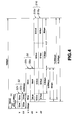
- a vector quantization output of the LSP equivalent to an output of the output terminal 131 of Fig. 1, that is an index of a codebook LSPidx, is supplied to an input terminal 200.
- the LSP index LSPidx is sent to an inverse vector quantization (inverse VQ) circuit 241 for LSPs of an LSP parameter reproducing unit 240 for inverse vector quantization or inverse matrix quantization into linear spectral pair (LSP) data.
- the LSP index thus quantized, is sent to an LSP interpolation circuit 242 for LSP interpolation.
- the interpolated data is converted in an LSP-to- ⁇ conversion circuit 243 into ⁇ -parameters, as LPC coefficients, which are then sent to LPC synthesis filters 215, 225 and to pitch spectral post-filters 216, 226.
- the index for vector quantization for MDCT coefficients IsxVq 1 from the input terminal 201 is supplied to an inverse VQ circuit 211 for inverse VQ and thence supplied to an inverse MDCT circuit 212 for inverse MDCT so as to be then overlap-added by an overlap-and-add circuit 213 and sent to a pitch synthesis filter 214.
- the pitch synthesis circuit 214 is supplied with the pitch lag L 1 and the pitch gain g 1 from the input terminals 202, 203, respectively.
- the pitch synthesis circuit 214 performs an inverse operation of pitch prediction encoding performed by the pitch inverted filter 215 of Fig.1,
- the resulting signal is sent to an LPC synthesis filter 215 and processed with LPC synthesis.
- the LPC synthesis output is sent to a pitch spectral post-filter 216 for post-filtering so as to be then taken out at an output terminal 219 as speech signal corresponding to a bit rate of 6 kbps.
- a pitch gain g 2 is supplied to input terminals 204, 205, 206 and 207 of Fig.4 to input terminals 204, 205, 206 and 207 of Fig.4 to input terminals 204, 205, 206 and 207 of Fig.4 to input terminals 204, 205, 206 and 207 of Fig.4 to input terminals 204, 205, 206 and 207 of Fig.4 to input terminals 204, 205, 206 and 207 of Fig.4 are respectively supplied to input terminals 204, 205, 206 and 207 of Fig.4 to input terminals 204, 205, 206 and 207 of Fig.4 are respectively supplied a pitch gain g 2 , a pitch lag L 2 , an index IsqVq 2 and a pitch gain g 1d for vector quantization of the MDCT coefficients from output terminals 144, 145, 146 and 147, respectively.
- the index IsxVq 2 for vector quantization of the MDCT coefficients from the input terminal 207 is sent to an inverse VQ circuit 220 for vector quantization and thence supplied to an adder 221 so as to be summed to the inverse VQed MDCT coefficients from the inverse VQ circuit 211.
- the resulting signal is inverse MDCTed by an inverse MDCT circuit 222 and overlap-added in an overlap-and-add circuit 223 so as to be thence supplied to a pitch synthesis filter 214.
- pitch synthesis filter 224 To this pitch synthesis filter 224 are supplied the pitch lag L 1 , pitch gain g 2 and the pitch lag L 2 from the input terminals 202, 204 and 205, respectively, and a sum signal of the pitch gain g 1 from the input terminal 203 summed to the pitch gain g 1d from the input terminal 206 at an adder 217.
- the pitch synthesis filter 224 synthesizes pitch residuals.
- An output of the pitch synthesis filter is sent to an LPC synthesis filter 225 for LPC synthesis.
- the LPC synthesized output is sent to a pitch spectral post-filter 226 for post-filtering.
- the resulting post-filtered signal is sent to an up-sampling circuit 227 for up-sampling the sampling frequency from e.g., 8 kHz to 16 kHz, and thence supplied to an adder 228.
- LSP index LSPidx H of the high range side from the output terminal 181 of Fig. 1.
- this LSP index LSPidx H is sent to an inverse VQ circuit 246 for the LSP of an LSP parameter reproducing unit 245 so as to be inverse vector-quantized to LSP data.
- LSP data are sent to an LSP interpolation circuit 247 for LSP interpolation.
- LSP interpolation circuit 247 for LSP interpolation.
- interpolated data are converted by an LSP-to- ⁇ converting circuit 248 to an ⁇ parameter of the LPC coefficients.
- the ⁇ -parameter is sent to a high-range side LPC synthesis filter 232.
- an index LPCidx that is a vector quantized output of the high-range side LPC residuals from the output terminal 173 of Fig.1.
- This index is inverse VQed by a high-range side inverse VQ circuit 231 and thence supplied to a high-range side LPC synthesis filter 232.
- the LPC synthesized output of the high-range side LPC synthesis filter 232 has its sampling frequency up-sampled by an up-sampling circuit 233 from e.g., 8 kHz to 16 kHz and is converted into frequency-domain data by fast FFT by an FFT circuit 234 as orthogonal transform means.
- the resulting frequency-domain signal is then frequency-shifted to a high range side by a frequency shift circuit 235 and inverse FFTed by an inverse FFT circuit 236 into high-range side time-domain signals which then are supplied via an overlap-and-add circuit 237 to the adder 28.
- the time-domain signals from the overlap-and-add circuit is summed by the adder 228 to the signal from the up-sampling circuit 227.
- an output is taken out at output terminal 229 as speech signals corresponding to a portion of the bit rate of 16 kbps.
- the entire 16 kbps bit rate signal is taken out after summing to the signal from the output terminal 219.
- the encoder configured as shown in Fig.3 is used for 2 kbps encoding and a maximum common owned portion or common owned data is shared with the configuration of Fig. 1.
- the 16 kbps bitstream on the whole is flexibly used so that the totality of 16 kbps, 6 kbps or 2 kbps will be used depending on usage.
- the totality of the information of 2 kbps is used for 2 kbps encoding
- the information of 6 kbps and the information of 5.65 kbps are used if the frame as an encoding unit is voiced (V) and unvoiced (UV), respectively.
- the information of 15.2 kbps and the information of 14.85 kbps are used if the frame as an encoding unit is voiced (V) and unvoiced (UV), respectively.
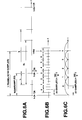
- the basic concept of the encoder shown in Fig.3 resides in that the encoder includes a first encoding unit 310 for finding short-term prediction residuals of the input speech signal, for example, LPC residuals, for performing sinusoidal analysis encoding, such as harmonic coding, and a second encoding unit 320 for encoding by waveform encoding by phase transmission of the input speech signal.
- the first encoding unit 310 and the second encoding unit 320 are used for encoding the voiced portion of the input signal and for encoding the unvoiced portion of the input signal, respectively.
- the first encoding unit 310 uses the configuration of encoding the LPC residuals by sinusoidal analysis encoding, such as harmonic encoding or multi-band encoding (MBE).
- the second encoding unit 320 uses the configuration of code excitation linear prediction (CELP) employing vector quantization by closed loop search of the optimum vector with the aid of the analysis-by-synthesis method.
- CELP code excitation linear prediction
- the speech signal supplied to an input terminal 301 is sent to an LPC inverted filter 311 and to an LPC analysis quantization unit 313 of the first encoding unit 310.
- the LPC coefficients or the so-called ⁇ -parameters obtained by the LPC analysis quantization unit 313 are sent to the LPC inverted filter 311 for taking out linear prediction residuals (LPC residuals) of the input speech signal.
- LPC residuals linear prediction residuals
- the LPC analysis quantization unit 313 takes out a quantized output of the linear spectral pairs (LSPs) as later explained.
- the quantized output is sent to an output terminal 302.
- the LPC residuals from the LPC inverted filter 311 are sent to a sinusoidal analysis encoding unit 314 where the pitch is detected and the spectral envelope amplitudes are calculated.
- V/UV discrimination is performed by a V/UV discrimination unit 315.
- the spectra envelope amplitude data from the sinusoidal analysis encoding unit 314 is sent to a vector quantizer 316.
- the codebook index from the vector quantizer 316, as a vector quantization output of the spectral envelope, is sent via a switch 317 to an output terminal 303.
- An output of the sinusoidal analysis encoding unit 314 is sent via a switch 318 to an output terminal 304.
- the V/UV discrimination output of the V/UV discrimination unit 315 is sent to an output terminal 305, while being sent as a control signal to switches 317, 318. If the input signal is the voiced signal (V), the index and the pitch are selected and taken out at the output terminals 303, 304, respectively.
- V voiced signal
- the second encoding unit 320 of Fig.3 has, in the present embodiment, the CELP encoding configuration and executes vector quantization of the time-domain waveform using a closed loop search by an analysis by synthesis method in which an output of a noise codebook 321 is synthesized by a weighted synthesis filter 322, the resulting weighted speech is sent to a subtractor 323 where an error is found from the speech obtained on passing the speech signal supplied to the input terminal 301 through a perceptually weighting filter 325, the resulting error is sent to a distance calculation circuit 324 for distance calculation and a vector which minimizes the error is searched by the nose codebook 321.
- This CELP encoding is used for encoding the unvoiced portion as described above, such that the codebook index as the UV data from the noise codebook 321 is taken out at an output terminal 307 via a switch 327 which is turned on when the result of V/UV discrimination from the V/UV discrimination unit 315 indicated UV.
- the above-described LPC analysis quantization unit 313 of the encoder may be used as part of the LPC analysis quantization unit 130 of Fig. 1, such that an output at the terminal 302 may be used as an output of the pitch analysis circuit 115 of Fig. 1.
- This pitch analysis circuit 115 may be used in common with a pitch outputting portion within the sinusoidal analysis encoding unit 314.
- the bitstream S2 of 2 kbps has an inner structure for the unvoiced analysis synthesis frame different from one for the voiced analysis synthesis frame.
- a bitstream S2v of 2 kbps for V is made up of two portions S2 ve and S2 va
- a bitstream S2u of 2 kbps for UV is made up of two portions S2 ue and S2 ua .
- the portion S2 ve has a pitch lag equal to 1 bit per 160 samples per frame (1 bit/160 samples) and an amplitude Am of 15 bits/160 samples, totalling at 16 bits/160 samples. This corresponds to data of 0.8 kbps bit rate for the sampling frequency of 8 kHz.
- the portion S2 ue is composed of LPC residuals of 11 bits/80 samples and a spare 1 bit/160 samples, totalling at 23 bits/160 samples. This corresponds to data having a bit rate of 1.15 kbps bit rate.
- the remaining portions S2 va and S2 ua represent common portions or common owned portions with the 6 kbps and 16 kbps.
- the portion S2 va is made up of the LSP data of 32 bits/320 samples, V/UV discrimination data of 1 bit/160 samples and a pitch lag of 7 bits/160 samples, totalling at 24 bits/160 samples. This corresponds to data having a bit rate of 1.2 kbps bit rate.
- the portions S2 ua is made up of the LSP data of 32 bits/320 samples and V/UV discrimination data of 1 bit/160 samples, totalling at 17 bits/160 samples. This corresponds to data having a bit rate of 0.85 kbps bit rate.
- the bitstream S6v of 6 kbps for V is made up of two portions S6 va and S6 vb
- the bitstream S6u of 6 kbps for UV is made up of two portions S6 ua and S6 ub
- the portion S6 va has data contents in common with the portion S2 va, as explained previously.
- the portion S6 vb is made up of a pitch gain of 6 bits/160 samples and pitch residuals of 18 bits/32 samples, totalling at 96 bits/160 samples. This corresponds to data of 4.8 kbps bit rate.
- the portion S6 ua has data contents in common with the portion S2 ua
- the portion S6 ub has data contents in common with the portion S6 ub .
- bitstream S16 of 16 kbps has an inner structure for the unvoiced analysis frame different in part from one for the voiced analysis frame.
- a bitstream S16v of 16 kbps for V is made up of four portions S16 va , S16 vb , S16 vc and S16 vd
- a bitstream S16u of 16 kbps for UV is made up of four portions S16 ua , S16 ub , S16 uc and S6 ud
- the portion S16 va has data contents in common with the portions S2 va , S6 va
- the portion S16 vb has data contents in common with the portions S6 vb , S6 ub
- the portion S16 vc is made up of a pitch lag of 2 bits/160 samples, a pitch gain of 11 bits/160 samples, pitch residuals of 18 bits/32 samples and S/M mode data of 1 bit/160 samples, totaling 104 bits/160 samples.
- the S/M mode data is used for switching between two different sorts of codebooks for the speech and for music by the VQ circuit 124.
- the portion S16 vd is made up of a high-range LPC data of 5 bits/160 samples and a high-range LPC residuals of 15 bits/32 samples, totalling at 80 bits/160 samples. The corresponds to a bit rate of 4 kbps.
- the portion S16 ub has data contents in common with the portions S2 ua and S6 ua , while the portion S16 ub has data contents in common with the portions S16 vb , that is the portions S6 ub and S6 ub
- the portion S16 uc has data contents in common with the portion S16 vc
- the portion S16 ud has data contents in common with the portion S16 vd .
- an input terminal 11 corresponds to the input terminal 101 of Figs.1 and 3.
- the speech signal entering the input terminal 11 is sent to a band splitting circuit 12 corresponding to the LPF 102, sampling frequency converter 103, subtractor 106 and BPF 107 of Fig.1 so as to be split into a low-range signal and a high-range signal.
- the low-range signal from the band-splitting circuit 12 is sent to a 2k encoding unit 21 and a common portion encoding unit 22 equivalent to the configuration of Fig.3.
- the common portion encoding unit 22 is roughly equivalent to the LPC analysis quantization unit 130 of Fig.1 or to the LPC analysis quantization unit 310 of Fig.3.
- the pitch extracting portion in the sinusoidal analysis encoding unit of Fig.3 or the pitch analysis circuit 115 of Fig.1 may also be included in the common portion encoding unit 22.
- the low-range side signal from the band-splitting circuit 12 is sent to a 6k encoding unit 23 and to a 12k encoding unit 24.
- the 6k encoding unit 23 and the 12k encoding unit are roughly equivalent to the circuits 111 to 116 of Fig.1 and to the circuits 117, 118 and 122 to 128 of Fig. 1, respectively.
- the high-range side signals from the band-splitting circuit 12 are sent to a high-range 4k encoding unit 25.
- This high-range 4k encoding unit 25 roughly corresponds to the circuit 161 to 164, 171 and 172.
- the above-described technique for realizing scalability may be generalized as follows: That is, when multiplexing a first encoded signal obtained on first encoding of an input signal and a second encoded signal obtained on second encoding of the input signal so as to have a portion in common with a part of the first encoding signal and another portion not in common with the first encoded signal, the first encoding signal is multiplexed with the portion of the second encoded signal excluding the portion in common with the first encoded signal.
- the frame interval is N samples, such as 160 samples, and analysis is performed once per frame, as shown in Fig.6A.
- the value obtained after pitch tracking may be used as an optimum pitch lag L 1 for avoiding abrupt pitch changes.
- the pitch gain vector g 1 is vector-quantized to give a code index g 1 .
- Which of these values is used is determined by calculating the power of the pitch residuals corresponding to the respective lags.
- X 0 (0) , X 1 (0) , X 2 (0) are X 0 (-1) , X 0 , (1) X 1 , (1) X 1 , (-1) X 2 , (-1) X 2 ,.
- the gain needs to be calculated again to transmit the resulting data, despite the fact that the pitch gain for the number of dimensions N of X is available.
- g 1 is largest, while g 0 and g 2 are close to zero, or vice versa, with the vector g having the strongest correlation among the three points.
- the vector g 1d is estimated to have smaller variance than the original vector g , such that quantization can be achieved with a smaller number of bits.
- Fig.6B shows the phase of the LPC coefficients interpolated with a rate eight times as high as the frame frequency.
- the LPC coefficients are used for calculating prediction residuals by the inverted LPC filter 111 of Fig.1 and also for the LPC synthesis filters 215, 225 of Fig.2 and for the pitch spectral post-filters 216, 226.
- the pitch residuals are windowed with 50% overlap and transformed with MDCT. Weighting vector quantization is executed in the resulting domain.
- the transform length may be set arbitrarily, a smaller number of dimensions is used in the present embodiment in view of the following points.
- the pitch residuals r pi (n) of this sub-frame are multiplied with a windowing function w(n) capable of canceling the MDCT aliasing to produce w(n)•r pi (n) which is processed with MDCT transform.
- w n 1- cos2 ⁇ n +0.5 /64 may, for example, be employed.
- the transform calculations may be performed using FFT by:
- the MDCT coefficient c i (k) of each sub-frame is vector-quantized with weighting, which is now explained.
- the distance following the synthesis is represented by where H is a synthesis filter matrix, M is a MDCT matrix, c i is a vector representation of c j (k) and ⁇ i is a vector representation of quantized ⁇ j (k) .
- h i 2 and w i 2 may be found as an FFT power spectrum of the impulse response of the synthesis filter H(z) and the perceptual weighting filter W(z) where P is the number of analysis and ⁇ a, , ⁇ b are coefficients for weighting.
- the vector quantization is performed by shape and gain quantization.
- the optimum encoding and decoding conditions during learning are now explained.
- the gain codebook is g
- the input during training that is the MDCT coefficient in each sub-frame is x and the weight for each sub-frame is W'
- the optimum encoding condition is selection of (g, s) which will minimize D 2 .
- S opt which maximizes ( s ⁇ t w 't w ' x ⁇ ) 2 s ⁇ t w 't w ' s ⁇ is searched for the shape codebook and, for the gain codebook, is searched for a shape codebook and g opt closest to s ⁇ t opt w 't w ' x ⁇ s ⁇ t opt w 't w ' s ⁇ opt is searched for the gain codebook for this s opt .
- the shape and gain codebooks may be produced by the generalized LLoyd algorithm while the above first and second steps are found repeatedly.
- the MDCTed pitch residuals are vector-quantized, using the codebook thus prepared, and the index thereby obtained is transmitted along with the LPC (in effect LSP), pitch and the pitch gain.
- the decoder side executes inverse VQ and pitch-LPC synthesis to produce the reproduced sound.
- the number of times of pitch gain calculations is increased and the pitch residual MDCT and vector quantization are executed in multiple stages for enabling a higher rate operation.
- FIG.7A An illustrative example is shown in Fig.7A, in which the number of stages is two and the vector quantization is sequential multi-stage VQ.
- An input to the second stage is the decoded result of the first stage subtracted from pitch residuals of higher precision produced from L 2 , g 2 and g 1d . That is, an output of the first-stage MDCT circuit 113 is vector-quantized by the VQ circuit 114 to find the representative vector or a dequantized output which is inverse MDCTed by an inverse MDCT circuit 113a.
- the resulting output is sent to a subtractor 128' for subtraction from the residuals of the second stage (output of the inverted pitch filter 122 of Fig.1), An output of the subtractor 128' is sent to a MDCT circuit 123' and the resulting MDCTed output is quantized by the VQ circuit 124.
- This can be configured similarly to the equivalent configuration of Fig.7B in which MDCT is not performed.
- Fig.1 uses the configuration of Fig.7B.
- the post-filters realize post-filter characteristics p(Z) by pitch emphasis, high range emphasis and a tandem connection of spectrum emphasis filters.
- g i and L are the pitch gain and the pitch lag as found by pitch prediction
- Figs.8A and 8B show the windowing functions for the low-rate operation and for the high-rate operation, respectively.
- the window with a width of 80 samples of Fig.8B is used twice during synthesis of 160 samples (20 msec).
- the encoder side VQ circuit 124 shown in Fig.1 is explained.
- This VQ circuit 124 has two different sorts of codebooks for speech and for music switched and selected responsive to the input signal. That is, if the quantizer configuration is fixed for quantization of musical sound signals, the codebook owned by the quantizer becomes optimum with the properties of the speech and the musical sound as used during learning. Thus, if the speech and the musical sound are learned together, and if the two are significantly different in their properties, the as-learned codebook has an average property of the two, as a result of which the performance or mean S/N value may be presumed not to be raised in case the quantizer is configured with a sole codebook.
- the code volumes prepared using the learning data for plural signals having different properties are switched for improving the quantizer performance.
- Fig.9 shows a schematic structure of a vector quantizer having such two sorts of codebooks CB A , CB B .
- an input signal supplied to an input terminal 501 is sent to vector quantizers 511, 512.
- These vector quantizers 511, 512 own codebooks CB A , CB B .
- the representative vectors or dequantized outputs of the vector quantizers 511, 512 are sent to subtractors 513, 514, respectively, where the difference from the original input signal are found to produce error components which are sent to a comparator 515.
- the comparator 515 compares the error components and selects an index which is a smaller one of quantization outputs of the vector quantizers 511, 512 by a changeover switch 516. The selected index is sent to an output terminal 502.
- the switching period of the changeover switch 516 is selected to be longer than the period or the quantization unit time of each of the vector quantizers 511, 512. For example, if the quantization unit is a sub-frame obtained by dividing a frame into eight, the changeover switch 516 is changed over on the frame basis.
- E A (k) ⁇ W k ( X ⁇ - C ⁇ Ai ) ⁇
- E B (k) ⁇ W k ( X ⁇ - C ⁇ Bi ) ⁇
- W k is a weighted matrix at the sub-frame k and C Aj
- C Bj denote representative vectors associated with the indices i and j of the codebooks CB A , CB B , respectively.
- codebooks most appropriate for a given frame is used by the sum of the distortion in the frame.
- the following two methods may be used for such selection.
- the first method is to perform quantization using only the codebooks CB A , CB B , to find the sum of the distortions in the frame ⁇ k E A (k) and ⁇ k E B (k) and to use the codebook CB A or CB B which gives a smaller one of the sums of the distortion for the entire frame.
- Fig. 10 shows a configuration for implementing the first method, in which the parts or components corresponding to those shown in Fig.9 are denoted by the same reference numerals and suffix letters such as a, b, ...correspond to the sub-frame k.
- the codebook CB A the sum for the frame of outputs of subtractors 513a, 513b, ...513n, which give the sub-frame-based distortions, is found at an adder 517.
- the codebook CB B the sum for the frame of the sub-frame-based-distortions is found at an adder 518. These sums are compared to each other by the comparator 515 for obtaining a control signal or a selection signal for codebook switching at the terminal 503.
- the second method is to compare the distortions E A (k) and E B (k) for each sub-frame and to evaluate the results of comparison for the totality of sub-frames in the frame for switching codebook selection.
- Fig.11 shows a configuration for implementing the second method, in which an output of the comparator 516 for sub-frame-based comparison is sent to a judgment logic 519 for giving judgment by majority decision for producing a one-bit codebook switching selection flag at a terminal 503.
- This selection flag is transmitted as the above-mentioned S/M (speech/music) mode data.
- the frequency conversion processing includes a band extraction step of taking out at least one band of the input signal, an orthogonal transform step of transforming the signal of at least one extracted band into frequency-domain signal, a shifting step of shifting the orthogonal transformed signal on the frequency domain to another position or band, and an inverse orthogonal transform step of converting the signal shifted on the frequency domain by inverse orthogonal transform into time-domain signals.
- Fig.12 shows the structure for the above-mentioned frequency transform in more detail.
- parts or components corresponding to those of Fig,1 are denoted by the same numerals.
- broad-range speech signals having components of 0 to 8 kHz with the sampling frequency of 16 kHz are supplied to the input terminal 101.
- the band of 0 to 3.8 kHz for example, is separated as the low-range signal by the low-pass filter 102, and the remaining frequency components obtained by subtracting the low-range side signal from the original broad-band signal by the subtractor 151 is separated as the high-frequency component.
- These low-range and high-range signals are processed separately.
- the high-range side signal has a frequency width of 4.5 kHz in a range from 3.5 kHz to 8 kHz, which is still left after passage through the LPF 102. This bandwidth needs to be reduced to 4 kHz in view of signal processing with down-sampling.
- the band of 0.5 kHz ranging from 7.5 kHz to 8 kHz is cut by a band-pass filter (BPF) 107 or an LPF.
- BPF band-pass filter
- FFT fast Fourier transform
- the number of samples is divided at an interval of a number of samples equal to powers of 2, for example, 512 samples, as shown for example in Fig.13A.
- the samples are advanced every 80 samples for facilitating the subsequent processing.
- a Hamming window of a length of 320 samples is then applied by a Hamming windowing circuit 109.
- the number of samples of 320 is selected to be four times as large as 80, which is the number by which the samples are advanced at the time of frame division. This enables four waveforms to be added later on in superimposition at the time of frame synthesis by overlap-and-add as shown in Fig.13B.
- the 512-sample data is then FFTed by the FFT circuit 161 for conversion into frequency-domain data.
- the frequency-domain data is then shifted by the frequency shifting circuit 162 to an other position or to an other range on the frequency axis.
- the principle of lowering the sampling frequency by this shifting on the frequency axis is to shift the high-range side signal shown shaded in Fig.14A to a low-range side as indicated in Fig. 14B and to down-sample the signal as shown in Fig.14C.
- the frequency components aliased with fs/2 as the center at the time of shifting on the frequency axis from Fig.14A to Fig.14B are shifted in the opposite direction. This enables the sampling frequency to be lowered to fs/n if the range of the sub-band is lower than fs/2n.
- the frequency shifting circuit 162 to shift high-range side frequency-domain data, shown shaded in Fig.15, to a low-range side position or band on the frequency axis.
- 512 frequency-domain data, obtained on FFTing 512 time-domain data are processed so that 127 data, namely 113rd to 239th data, are shifted to the first to 127th positions or bands, respectively, while 127 data, namely 273rd to 399th data, are shifted to the 395th to 511th positions or bands, respectively.
- the 0th data of the frequency-domain signal is a dc component and devoid of a phase component so that data at this position needs to be a real number, such that the frequency component, which is generally a complex number, cannot be introduced in this position.
- the 256th data representing fs/2 generally the N/2nd data, is also invalid and is not used. That is, the range of 0 to 4 kHz should more correctly be represented as 0 ⁇ f ⁇ 4 kHz.
- the shifted data is inverse FFTed by the inverse FFT circuit 163 for restoring the frequency-domain data to time-domain data.
- These 512-sample-based time-domain signals are overlapped by the overlap-and-add circuit 166 every 80 samples, as shown in Fig.13B, for summing the overlapped portions.
- the signal obtained by the overlap-and add circuit 166 is limited by 16 kHz sampling to 0 to 4 kHz and hence is down-sampled by the down-sampling circuit 164. This gives a signal of 0 to 4 kHz by frequency shifting with 8 kHz sampling. This signal is taken out at an output terminal 169 and thence supplied to the LPC analysis quantization unit 130 and to the LPC inverted filter 171 shown in Fig.1.
- the decoding operation on the decoder side is implemented by a configuration shown in Fig.16,
- Fig.16 corresponds to the configuration downstream of the up-sampling circuit 233 in Fig.2 and hence the corresponding portions are indicated by the same numerals.
- FFT processing is preceded by up-sampling in Fig.2, FFT processing is followed by up-sampling in the embodiment of Fig.16.
- the high-range side signal shifted to 0 to 4 kHz by 8 kHz sampling such as an output signal of the high-range side LPC synthesis filter 232 of Fig.2, is supplied to the terminal 241 of Fig.16.
- This signal is divided by the frame dividing circuit 242 into signals having a frame length of 256 samples, with an advancing distance of 80 samples, for the same reason as that for frame division on the encoder side. However, the number of samples is halved because the sampling frequency is halved.
- the signal from the frame division circuit 242 is multiplied by a Hamming windowing circuit 243 with a Hamming window 160 samples long in the same way as for the encoder side (the number of samples is, however, one-half).
- the resulting signal is then FFTed by the FFT circuit 234 with a length of 256 samples for converting the signal from the time axis into frequency axis.
- the next up-sampling circuit 244 provides a 512-sample frame length from the frame length of 216 samples by zero-stuffing as shown in Fig.15B. This corresponds to conversion from Fig.14C to Fig.14B.
- the frequency shifting circuit 235 then shifts the frequency-domain data to an other position or band on the frequency axis for frequency shifting by +3.5 kHz. This corresponds to conversion from Fig.14B to Fig.14A.
- the resulting frequency-domain signals are inverse FFTed by the inverse FFT circuit 236 for restoration to time-domain signals.
- the signals from the inverse FFT circuit 236 range from 3.5 kHz to 7.5 kHz with 16 kHz sampling.
- the next overlap-and-add circuit 237 overlap-adds the time-domain signals every 80 samples, for each 512-sample frame, for restoration to continuous time-domain signals.
- the resulting high-range side signal is summed by the adder 228 to the low-range side signal and the resulting sum signal is outputted at the output terminal 229.
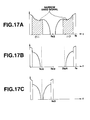
- the narrow band signals of 300 Hz to 3.4 kHz and the broad-band signals of 0 to 7 kHz are produced by 16 kHz sampling, as shown in Fig. 17, the low-range signal of 0 to 300 Hz is not contained in the narrow band.
- the high-range side of 3.4 kHz to 7 kHz is shifted to a range of 300 Hz to 3.9 kHz so as to be contacted with the low-range side, the resulting signal ranges from 0 to 3.9 kHz, so that the sampling frequency fs may be halved, that is may be 8 kHz.
- a broad-band signal is to be multiplexed with a narrow-band signal contained in the broad-band signal
- the narrow-band signal is subtracted from the broad-band signal and high-range components in the residual signal are shifted to the low-range side for lowering the sampling rate.
- a sub-band of an arbitrary frequency may be produced from another arbitrary frequency and processed with a sampling frequency twice the frequency width for flexibly coping with given applications.
- the aliasing noise is usually generated in the vicinity of the band division frequency with the use of a QMF. Such aliasing noise can be evaded with the present method for frequency conversion.
- the present invention is not limited to the above-described embodiments.
- the configuration of the speech encoder of Fig.1 or the configuration of the speech decoder of Fig.2, represented by hardware may also be implemented by a software program using a digital signal processor (DSP).
- DSP digital signal processor
- plural frames of data may be collected and quantized with matrix quantization instead of with vector quantization.
- the speech encoding or decoding method according to the present invention is not limited to the particular configuration described above.
- the present invention may be applied to a variety of usages such as pitch or speed conversion, computerized speech synthesis or noise suppression, without being limited to transmission or recording/reproduction.
- the above-described signal encoder and decoder may be used as a speech codec used in a portable communication terminal or a portable telephone as shown for example in Figs.18 and 19.
- Fig.18 shows the configuration of a sender of the portable terminal employing a speech encoding unit 160 configured as shown for example in Fig.1 and Fig.3.
- the speech signal collected by a microphone 661 in Fig.18 is amplified by an amplifier 662 and converted by an A/D converter 663 into a digital signal which is sent to a speech encoding unit 660.
- This speech encoding unit 660 is configured as shown in Figs.1 and 3.
- To the input terminal 101 of the encoding unit 660 is supplied the digital signal from the A/D converter 663.
- the speech encoding unit 660 performs encoding as explained in connection with Figs.1 and 3.
- Output signals of the output terminals of Figs.1 and 3 are sent as output signals of the speech encoding unit 660 to a transmission path encoding unit 664 where channel decoding is performed and the resulting output signals are sent to a modulation circuit 665 and demodulated so as to be sent via a D/A converter 666 and an RF amplifier 667 to an antenna 668.
- Fig.19 shows a configuration of a receiving side of the portable terminal employing a speech decoding unit 760 configured as shown in Fig.2.
- the speech signal received by the antenna 761 of Fig.19 is amplified by an RF amplifier 762 and sent via an A/D converter 763 to a demodulation circuit 764 so that demodulated signals are supplied to a transmission path decoding unit 765.
- An output signal of the demodulation circuit 764 is sent to a speech decoding unit 760 configured as shown in Fig.2.
- the speech decoding unit 760 performs signal decoding as explained in connection with Fig.2.
- An output signal of an output terminal 201 of Fig.2 is sent as a signal of the speech decoding unit 760 to a D/A converter 766.
- An analog speech signal from the D/A converter 766 is sent via an amplifier 767 to a speaker 768.
Abstract
Description
- This invention relates to a method and apparatus for encoding an input signal, such as a broad-range speech signal. More particularly, it relates to a signal encoding method and apparatus in which the frequency spectrum is split into a telephone band for which sufficient clarity as speech can be obtained and the remaining band and in which signal encoding can be realized by an independent codec as long as the telephone band is concerned.
- There are a variety of methods known for compressing audio signals, inclusive of speech and acoustic signals, by exploiting statistic properties of the audio signals and psychoacoustic characteristics of the human being. The encoding methods may be roughly classified into encoding on the time axis, encoding on the frequency axis and analysis synthesis encoding.
- Among the known techniques for high efficiency encoding for speech signals or the like, there are a harmonic encoding, a sinusoidal analytic encoding, such as multi-band excitation (MBE) encoding, a sub-band encoding (SBC), a linear predictive coding (LPC), discrete cosine transform (DCT), modified DCT (MDCT) and fast Fourier transform (FFT).
- There have also hitherto been known a variety of encoding techniques for dividing an input signal into plural bands prior to encoding. However, since the encoding for the lower frequency range is performed by the same unified method as that for the higher frequency range, there are occasions wherein an encoding method appropriate for the low frequency range signals has only poor encoding efficiency for the encoding of the high frequency range signals, or vice versa. In particular, optimum encoding occasionally cannot be performed when the signal is transmitted with a low bit rate.
- Although the signal decoding devices now in use are designed to operate with various different bit rates, it is inconvenient to use different devices for the different bit rates. That is, it is desirable that a sole device can encode or decode signals of plural different bit rates.
- Meanwhile, it has recently been a desideratum that a bitstream itself has scalability such that a bitstream having a high bit rate is received and, if the bitstream is decoded directly, high-quality signals are produced, whereas, if a specified portion of the bitstream is decoded, signal of low sound quality are produced.
- Heretofore, a signal to be processed is roughly quantized on the encoding side to produce a bitstream with a low bit rate. For this bitstream, the quantization error produced on quantization is further quantized and added to the bitstream of the low bit rate to produce a high bit rate bitstream. In this case, if the encoding method remains essentially the same, the bitstream can have scalability as described above, that is, a high-quality signal can be obtained by directly decoding the high bit rate bitstream, while a low bit rate signal can be reproduced by taking out and decoding a portion of the bitstream.
- However, the above-mentioned complete inclusive relation cannot be constituted with ease if it is desired to encode the speech at, for example, three bit rates of 2 kbps, 6 kbps and 16 kbps, while maintaining scalability.
- That is, for encoding with as high signal quality as possible, waveform encoding is preferably performed with a high bit rate. If waveform encoding cannot be achieved smoothly, encoding has to be performed using a model for a low bit rate. The above inclusive relation in which the high bit rate includes the low bit rate cannot be achieved because of the difference in the information for encoding.
- It is therefore an object of the present invention to provide a speech encoding method and apparatus in which, in band splitting for encoding, the playback speech with a high quality may be produced with a smaller number of bits, and signal encoding for a pre-set band, such as a telephone band, can be realized by independent codec.
- It is another object of the present invention to provide a method for multiplexing encoded signals in which plural signals which cannot be encoded by the same method because of a significant difference in the bit rates are adapted to have as much common information as possible and encoded by essentially different methods for assuring scalability.
- It is yet another object of the present invention to provide a signal encoding apparatus employing the multiplexing method for multiplexing the encoded signal.
- In one aspect, there is provided a signal encoding method including a band-splitting step for splitting an input signal into plurality of bands and encoding signals of the bands in a different manner depending on signal characteristics of the bands.
- In another aspect, the present invention provides a method and apparatus for multiplexing an encoded signal having speech encoding means in turn having means for multiplexing a first encoded signal obtained on first encoding of an input signal employing a first bit rate and a second encoded signal obtained on second encoding of the input signal and means for multiplexing the first encoded signal and a portion of the second encoded signal excluding the portion thereof owned in common by the first encoded signal. The second encoding has a portion in common with only a portion of the first encoding and a portion not in common with the first encoding. The second encoding employs a second bit rate different from the bit rate for the first encoding.
- According to the present invention, the input signal is split into plural bands and signals of the bands thus split are encoded in a different manner depending on signal characteristics of the split bands. Thus a decoder operation with different rates is enabled and encoding may be performed with an optimum efficiency for each band thus improving the encoding efficiency.
- By performing short-term prediction on the signals of a lower side one of the bands for finding short-term prediction residuals, performing long-term prediction on the short-term prediction residuals thus found and by orthogonal transforming the long-term prediction residuals thus found, a higher encoding efficiency and a reproduced speech of superior quality may be achieved.
- Also, according to the present invention, at least a band of the input signal is taken out, and the signal of the band thus taken out is orthogonal-transformed into a frequency-domain signal. The orthogonal-transformed signal is shifted on the frequency axis to another position or band and subsequently inverse orthogonal-transformed to time-domain signals, which are encoded. Thus the signal of an arbitrary frequency band is taken out and converted into a low-range side for encoding with a low sampling frequency.
- In addition, a sub-band of an arbitrary frequency width may be produced from an arbitrary frequency so as to be processed with a sampling frequency twice the frequency width thus enabling an application to be dealt with flexibly.
- The present invention will be more clearly understood from the following description, given by way of example only, with reference to the accompanying drawings in which:
- Fig. 1 is a block diagram showing a basic structure of a speech signal encoding apparatus for carrying out the encoding method embodying the present invention.
- Fig.2 is a block diagram for illustrating the basic structure of a speech signal decoding apparatus.
- Fig.3 is a block diagram for illustrating the structure of another speech signal encoding apparatus.
- Fig.4 illustrates scalability of a bitstream of transmitted encoded data.
- Fig.5 is a schematic block diagram showing the entire system of the encoding side according to the present invention.
- Figs.6A, 6B and 6C illustrate the period and the phase of main operations for encoding and decoding.
- Figs.7A and 7B illustrate vector quantization of MDCT coefficients.
- Figs.8A and 8B illustrate examples of windowing functions applied to a post-filter output.
- Fig.9 shows an illustrative vector quantization device having two sorts of codebooks.
- Fig.10 is a block diagram showing a detailed structure of a vector quantization apparatus having two sorts of codebooks.
- Fig. 11 is a block diagram showing another detailed structure of a vector quantization apparatus having two sorts of codebooks.
- Fig. 12 is a block diagram showing the structure of an encoder for frequency conversion.
- Figs. 13A, 13B illustrate frame splitting and overlap-and-add operations.
- Figs.14A, 14B and 14C illustrate an example of frequency shifting on the frequency axis.
- Figs. 15A and 15B illustrate data shifting on the frequency axis.
- Fig.16 is a block diagram showing the structure of a decoder for frequency conversion.
- Figs.17A, 17B and 17C illustrate another example of frequency shifting on the frequency axis.
- Fig. 18 is a block diagram showing the structure of a transmitting side of a portable terminal employing a speech encoding apparatus of the present invention.
- Fig. 19 is a block diagram showing the structure of a receiving side of a portable terminal employing a speech signal decoding apparatus associated with Fig.18.
- Preferred embodiments of the present invention will now be explained in detail.
- Fig.1 shows an encoding apparatus (encoder) for broad-range speech signals for carrying out the speech encoding method according to the present invention.
- The basic concept of the encoder shown in Fig.1 is that the input signal is split into plural bands and the signals of the split bands are encoded in a different manner depending on signal characteristics of the respective bands. Specifically, the frequency spectrum of the broad-range input speech signals is split into plural bands, namely the telephone band for which sufficient clarity as speech can be achieved, and a band on the higher side relative to the telephone band. The signals of the lower band, that is the telephone band, are orthogonal-transformed after short-term prediction such as linear predictive coding (LPC) followed by long-term prediction, such as pitch prediction, and the coefficient obtained on orthogonal transform are processed with perceptually weighted vector quantization. The information concerning long-term prediction, such as pitch or pitch gain, or parameters representing the short-term prediction coefficients, such as LPC coefficients, are also quantized. The signals of the band higher than the telephone band are processed with short-term prediction and then vector-quantized directly on the time axis.
- The modified DCT (MDCT) is used as the orthogonal transform. The conversion length is shortened for facilitating weighting for vector quantization. In addition, the conversion length is set to 2N, that is to a value equal to powers of 2, for enabling high processing speed by employing fast Fourier transform (FFT). The LPC coefficients for calculating the weighting for vector quantization of the orthogonal transform coefficients and for calculating the residuals for short-term prediction (similarly for a post-filter) are the LPC coefficients smoothly interpolated from the LPC coefficients found in the current frame and those found in the past frame, so that the LPC coefficients used will be optimum for each sub-frame being analyzed. In performing the long-term prediction, prediction or interpolation is carried out a number of times for each frame and the resulting pitch lag or pitch gain is quantized directly or after finding the difference. Alternatively, a flag specifying the method for interpolation is transmitted. For prediction residuals the variance of which becomes smaller with an increased number of times (frequency) of prediction, multi-stage vector quantization is carried out for quantizing the difference of the orthogonal transform coefficients. Alternatively, only the parameters for a sole band among the split bands are used for enabling plural decoding operations with different bit rates by all or part of a sole encoded bitstream.
- Reference is had to Fig. 1.
- To an
input terminal 101 of Fig.1 are supplied broad-band speech signals in a range of, for example, from 0 to 8 kHz with a sampling frequency Fs of, for example, 16 kHz. The broad-band speech signals from theinput terminal 101 are split by a low-pass filter 102 and asubtractor 106 into low-range telephone band signals of, for example, 0 to 3.8 kHz, and high-range signals, such as signals in a range of, for example, from 3.8 kHz to 8 kHz. The low-range signals are decimated by asampling frequency converter 103 in a range satisfying the sampling theorem to provide e.g., 8 kHz-sampling signals. - The low-range signals are multiplied by an LPC
analysis quantization unit 130 by a Hamming window with an analysis length on the order of, for example, 256 samples per block. The LPC coefficients of, for example, 10 order, that is α-parameters, are found, and LPC residuals are found by an LPCinverted filter 111. During this LPC analysis, 96 of 256 samples of each block, functioning as a unit for analysis, are overlapped with the next block, so that the frame interval becomes equal to 160 samples. This frame interval is 20 msec for 8 kHz sampling. An LPCanalysis quantization unit 130 converts the α-parameters as LPC coefficients into linear spectral pair (LSP) parameters which are then quantized and transmitted. - Specifically, an
LPC analysis circuit 132 in the LPCanalysis quantization unit 130, fed with the low-range signals from thesampling frequency converter 103, applies a Hamming window to the input signal waveform, with the length of the order of 256 samples of the input signal waveform as one block, in order to find linear prediction coefficients, that is so-called α-parameters, by an autocorrelation method. The framing interval, as a data outputting unit, is e.g., 20 msec or 160 samples. - The α-parameters from the
LPC analysis circuit 132 are sent to an α-LSP conversion circuit 133 for conversion into linear spectra pair (LSP) parameters. That is, the α-parameters, found as direct type filter coefficients, are converted into, for example, ten LSP parameters, or five pairs of LSP parameters. This conversion is performed using, for example, the Newton-Rhapson method. The reason for conversion to the LSP parameters is that the LSP parameters are superior to the α-parameters in interpolation characteristics. - The LSP parameters from the α-
LSP conversion circuit 133 are vector- or matrix-quantized by anLSP quantizer 134. The vector quantization may be executed after finding the inter-frame difference, while matrix quantization may be executed on plural frames grouped together. In the present embodiment, 20 msec is one frame and two frames of the LSP parameters, each calculated every 20 msec, are grouped together and quantized by matrix quantization. - A quantization output of the
LSP quantizer 134, that is the indices of the LSP vector quantization, is taken out via a terminal 131, while the quantized LSP parameters, or dequantized outputs, are sent to anLSP interpolation circuit 136. - The function of the
LSP interpolation circuit 136 is to interpolate a set of the current frame and a previous frame of the LSP vectors vector-quantized every 20 msec by the LSP quantizer 134 in order to provide a rate required for subsequent processing. In the present embodiment, an octotuple rate and a quintuple rate are used. With the octotuple rate, the LSP parameters are updated every 2.5 msec. The reason is that, since analysis synthesis processing of the residual waveform leads to an extremely smooth waveform of the envelope of the synthesized waveform, extraneous sounds may be produced if the LPC coefficients are changed rapidly every 20 msec. That is, if the LPC coefficients are changed gradually every 2.5 msec, such extraneous sound may be prevented from being produced. - For inverted filtering of the input speech using the interpolated LSP vectors, occurring every 2.5 msecs, the LSP parameters are converted by an LSP to α
conversion circuit 137 into α-parameters which are the coefficients of the direct type filter of, for example, approximately 10 orders. An output of the LSP to αconversion circuit 137 is sent to an LPCinverted filter circuit 111 for finding the LPC residuals. The LPCinverted filter circuit 111 executes inverted filtering on the α-parameters updated every 2.5 msec for producing a smooth output. - The LSP coefficients, at an interval of 4 msec, interpolated at a quintuple rate by the
LSP interpolation circuit 136, are sent to a LSP-to α convertingcircuit 138 where they are converted into α-parameters. These α-parameters are sent to a vector quantization (VQ) weighting calculating circuit 139 for calculating the weighting used for quantization of MDCT coefficients. - An output of the LPC
inverted filter 111 is sent to pitchinverted filters - The long-term prediction is now explained. The long-term prediction is executed by finding the pitch prediction residuals by subtracting from the original waveform the waveform shifted on the time axis in an amount corresponding to the pitch lag or pitch period as found by pitch analysis. In the present embodiment, the long-term prediction is executed by three-point pitch prediction. Meanwhile, the pitch lag means the number of samples corresponding to the pitch period of sampled time-domain data.
- That is, the
pitch analysis circuit 115 executes pitch analysis once for each frame, that is with the analysis length of one frame. Of the results of pitch analysis, a pitch lag L1, is sent to the pitch invertedfilter 112 and to anoutput terminal 142, while a pitch gain is sent to a pitch gain vector quantization (VQ)circuit 116. In the pitchgain VQ circuit 116, the pitch gain values at three points of the three-point prediction are vector-quantized and a codebook index g1 is taken out at anoutput terminal 143, while a representative value vector or a dequantization output is sent to each of theinverted pitch filter 115, asubtractor 117 and anadder 127. Theinverted pitch filter 112 outputs a pitch prediction residual of the three-point prediction based upon the results of pitch analysis. The prediction residual is sent to, for example, anMDCT circuit 113, as orthogonal transform means. The resulting MDCTed output is quantized with perceptually weighted vector quantization by a vector quantization (VQ)circuit 114. The MDCTed output is quantized with perceptually weighted vector quantization by the vector quantization (VQ)circuit 114 by an output of the VQ weighting calculation circuit 139. An output of theVQ circuit 114, that is an index IdxVq1, is outputted at anoutput terminal 141. - In the present embodiment, a pitch inverted
filter 122, apitch analysis circuit 124 and a pitchgain VQ circuit 126 are provided as a separate pitch prediction channel. That is, a center of analysis is provided at an intermediate position of each pitch analysis center so that pitch analysis will be executed by apitch analysis circuit 125 at a one-half frame period. Thepitch analysis circuit 125 routes a pitch lag L2 to theinverted pitch filter 122 and to anoutput terminal 145, while routing the pitch gain to a pitchgain VQ circuit 126. The pitchgain VQ circuit 126 vector-quantizes the three-point pitch gain vector and sends an index g2 of the pitch gain as a quantization output to an output terminal 144, while routing its representative vector or a dequantization output to asubtractor 117. Since the pitch gain at the center of analysis of the original frame period is thought to be close to the pitch gain from the pitchgain VQ circuit 116, a difference between dequantization outputs of the pitchgain VQ circuits subtractor 117, as a pitch gain at the above center of analysis position. This difference is vector-quantized by a pitchgain VQ circuit 118 to produce an index g1d of the pitch gain difference which is sent to anoutput terminal 146. The representative vector or the dequantized output of the pitch gain difference is sent to anadder 127 and summed to the representative vector or the dequantized output from the pitchgain VQ circuit 126. The resulting sum is sent as a pitch gain to theinverted pitch filter 122. Meanwhile, the index g2 of the pitch gain obtained at theoutput terminal 143 is an index of the pitch gain at the above-mentioned mid position. The pitch prediction residuals from theinverted pitch filter 122 are MDCTed by aMDCT circuit 123 and sent to asubtractor 128 where the representative vector or the dequantized output from the vector quantization (VQ)circuit 114 is subtracted from the MDCTed output. The resulting difference is sent to theVQ circuit 124 for vector quantization to produce an index IdxVq2 which is sent to anoutput terminal 147. The This VQ circuit quantizes the difference signal by perceptually weighted vector quantization with an output of a VQ weighting calculation circuit 139. - The high-range signal processing is now explained.
- The signal processing for the high range signals basically consists in splitting the frequency spectrum of the input signals into plural bands, frequency-converting the signal of at least one high-range band to the low-range side, lowering the sampling rate of the signals converted to the low frequency side and encoding the signals lowered in sampling rate by predictive coding.
- The broad-range signal supplied to the
input terminal 101 of Fig.1 is supplied to thesubtractor 106. The low-range side signal, taken out by the low-pass filter (LPF) 102, such as the telephone band signal in a range of, for example, from 0 to 3.8 kHz, is subtracted form the broad-band signal. Thus thesubtractor 106 outputs a high-range side signal, such as a signal in a range of, for example, from 3.8 to 8 kHz. However, due to characteristics of theactual LPF 102, the components lower than 3.8 kHz are left in a minor amount in the output of thesubtractor 106. Thus the high-range side Signal processing is performed on the components not lower than 3.5 kHz, or components not lower than 3.4 kHz. - This high-range signal has a frequency width of from 3.5 kHz to 8 kHz from the
subtractor 106, that is a width of 4.5 kHz. However, since the frequency is shifted or converted by, for example, down-sampling, to a low range side, it is necessary to narrow the frequency range to, for example, 4 kHz. In consideration that the high range signal is combined with the low-range signal later on, the range of 3.5 kHz to 4 kHz, which is perceptually sensitive, is not cut, and the 0.5 kHz range from 7.5 kHz to 8 kHz, which is lower in power and psychoacoustically less critical as speech signals, is cut by the LPF or the band-pass filter 107. - The frequency conversion to the low-range side, which is then performed, is realized by converting the data into frequency domain data, using orthogonal transform means, such as a fast Fourier transform (FFT)
circuit 161, shifting the frequency-domain data by afrequency shifting circuit 162, and by inverse FFTing the resulting frequency-shifted data by aninverse FFT circuit 164 as inverse orthogonal transform means. - Form the
inverse FFT circuit 164, the high-range side of the input signal, for example, the signal ranging from 3.5 kHz to 7.5 kHz, converted to a low range side of from 0 to 4 kHz, is taken out. Since the sampling frequency of this signal can be represented by 8 kHz, it is down-sampled by a down-sampling circuit 164 to form a signal of a range from 3.5 kHz to 7.5 kHz with the sampling frequency of 8 kHz. An output of the down-sampling circuit 164 is sent to each of the LPCinverted filter 171 and to anLPC analysis circuit 182 of an LPCanalysis quantization unit 180. - The LPC
analysis quantization unit 180, configured similarly to the LPCanalysis quantization unit 130 of the low-range side, is now explained only briefly. - In the LPC
analysis quantization unit 180, theLPC analysis circuit 182, to which is supplied a signal from the down-sampling circuit 164, converted to the low range, applies a Hamming window, with a length of the order of 256 samples of the input signal waveform, as one block, and finds linear prediction coefficients, that is α-parameters, by, for example, an auto-correlation method. The α-parameters from theLPC analysis circuit 182 is sent to an α toLSP conversion circuit 183 for conversion into linear spectral pair (LSP) parameters. The LSP parameters from the α toLSP conversion circuit 183 are vector- or matrix-quantized by anLSP quantizer 184. At this time, an inter-frame difference may be found prior to vector quantization. Alternatively, plural frames may be grouped together and quantized by matrix quantization. In the present embodiment, the LSP parameters, calculated every 20 msec, are vector-quantized, with 20 msec as one frame. - A quantization output of the
LSP quantizer 184, that is an index LSPidxH, is taken out at a terminal 181, while a quantized LSP vector or the dequantized output, is sent to anLSP interpolation circuit 186. - The function of the
LSP interpolation circuit 186 is to interpolate a set of the previous frame and the current frame of the LSP, vectors vector-quantized by the LSP quantizer 184 every 20 msec, to provide a rate necessary for subsequent processing. In the present embodiment, the quadruple rate is used. - For inverted filtering the input speech signal using the interpolated LSP vectors, occurring at the interval of 5 msec, the LSP parameters are converted by an LSP-to-
α conversion circuit 187 into α-parameters as LPC synthesis filter coefficients. An output of the LSP-to-α conversion circuit 187 is sent to an LPCinverted filter circuit 171 for finding the LPC residuals. This LPCinverted filter 171 performs inverted filtering by the α-parameters updated every 5 msec for producing a smooth output. - The LPC prediction residual output from the LPC
inverted filter 171 is sent to an LPC residual VQ (vector quantization)circuit 172 for vector quantization. The LPCinverted filter 171 outputs an index LPCidx of the LPC residuals, which is outputted at anoutput terminal 173. - In the above-described signal encoder, part of the low-range side configuration is designed as an independent codec encoder, or the entire outputted bitstream is changed over to a portion thereof or vice versa for enabling signal transmission or decoding with different bit rates.
- That is, when transmitting all data from the respective output terminals of the configuration of Fig.I, the transmission bit rate becomes equal to 16 kbps (k bits/sec). If data is transmitted from part of the terminals, the transmission bit rate becomes equal to 6 kbps.
- Alternatively, if all data from all of the terminals of Fig.1 are transmitted, that is sent or recorded, and all data of 16 kbps are decoded on the receiving or reproducing side, high-quality speech signals of 16 kbps may be produced. On the other hand, if data of 6 kbps is decoded, speech signals having the sound quality corresponding to 6 kbps may be produced.
- In the configuration of Fig. 1, output data at the
output terminals - Referring to Fig.2, a signal decoding apparatus (decoder), as a counterpart of the encoder shown in Fig. 1, is explained.
- Referring to Fig.2, a vector quantization output of the LSP, equivalent to an output of the
output terminal 131 of Fig. 1, that is an index of a codebook LSPidx, is supplied to aninput terminal 200. - The LSP index LSPidx is sent to an inverse vector quantization (inverse VQ)
circuit 241 for LSPs of an LSPparameter reproducing unit 240 for inverse vector quantization or inverse matrix quantization into linear spectral pair (LSP) data. The LSP index, thus quantized, is sent to anLSP interpolation circuit 242 for LSP interpolation. The interpolated data is converted in an LSP-to-α conversion circuit 243 into α-parameters, as LPC coefficients, which are then sent to LPC synthesis filters 215, 225 and to pitchspectral post-filters - To input
terminals output terminals - The index for vector quantization for MDCT coefficients IsxVq1 from the
input terminal 201 is supplied to aninverse VQ circuit 211 for inverse VQ and thence supplied to aninverse MDCT circuit 212 for inverse MDCT so as to be then overlap-added by an overlap-and-add circuit 213 and sent to apitch synthesis filter 214. Thepitch synthesis circuit 214 is supplied with the pitch lag L1 and the pitch gain g1 from theinput terminals pitch synthesis circuit 214 performs an inverse operation of pitch prediction encoding performed by the pitch invertedfilter 215 of Fig.1, The resulting signal is sent to anLPC synthesis filter 215 and processed with LPC synthesis. The LPC synthesis output is sent to a pitchspectral post-filter 216 for post-filtering so as to be then taken out at anoutput terminal 219 as speech signal corresponding to a bit rate of 6 kbps. - To input
terminals output terminals - The index IsxVq2 for vector quantization of the MDCT coefficients from the
input terminal 207 is sent to aninverse VQ circuit 220 for vector quantization and thence supplied to anadder 221 so as to be summed to the inverse VQed MDCT coefficients from theinverse VQ circuit 211. The resulting signal is inverse MDCTed by aninverse MDCT circuit 222 and overlap-added in an overlap-and-add circuit 223 so as to be thence supplied to apitch synthesis filter 214. To thispitch synthesis filter 224 are supplied the pitch lag L1, pitch gain g2 and the pitch lag L2 from theinput terminals input terminal 203 summed to the pitch gain g1d from theinput terminal 206 at anadder 217. Thepitch synthesis filter 224 synthesizes pitch residuals. An output of the pitch synthesis filter is sent to anLPC synthesis filter 225 for LPC synthesis. The LPC synthesized output is sent to a pitchspectral post-filter 226 for post-filtering. The resulting post-filtered signal is sent to an up-sampling circuit 227 for up-sampling the sampling frequency from e.g., 8 kHz to 16 kHz, and thence supplied to anadder 228. - To the
input terminal 207 is also supplied an LSP index LSPidxH of the high range side from theoutput terminal 181 of Fig. 1. this LSP index LSPidxH is sent to aninverse VQ circuit 246 for the LSP of an LSPparameter reproducing unit 245 so as to be inverse vector-quantized to LSP data. These LSP data are sent to anLSP interpolation circuit 247 for LSP interpolation. These interpolated data are converted by an LSP-to-α converting circuit 248 to an α parameter of the LPC coefficients. The α-parameter is sent to a high-range sideLPC synthesis filter 232. - To an
input terminal 209 is also supplied an index LPCidx, that is a vector quantized output of the high-range side LPC residuals from theoutput terminal 173 of Fig.1. This index is inverse VQed by a high-range sideinverse VQ circuit 231 and thence supplied to a high-range sideLPC synthesis filter 232. The LPC synthesized output of the high-range sideLPC synthesis filter 232 has its sampling frequency up-sampled by an up-sampling circuit 233 from e.g., 8 kHz to 16 kHz and is converted into frequency-domain data by fast FFT by anFFT circuit 234 as orthogonal transform means. The resulting frequency-domain signal is then frequency-shifted to a high range side by afrequency shift circuit 235 and inverse FFTed by aninverse FFT circuit 236 into high-range side time-domain signals which then are supplied via an overlap-and-add circuit 237 to the adder 28. - The time-domain signals from the overlap-and-add circuit is summed by the
adder 228 to the signal from the up-sampling circuit 227. Thus, an output is taken out atoutput terminal 229 as speech signals corresponding to a portion of the bit rate of 16 kbps. The entire 16 kbps bit rate signal is taken out after summing to the signal from theoutput terminal 219. - Now, scalability is explained.
- In the configuration shown in Figs. 1 and 2, two transmission bit rates of 6 kbps and 16 kbps are realized with encoding/decoding systems substantially similar to each other for realizing scalability in which a 6 kbps bitstream is completely included in the 16 kbps bitstream. If encoding/decoding with a drastically different bit rate of 2 kbps is desired, this complete inclusive relation is difficult to achieve.
- If the same encoding/decoding system cannot be applied, it is desirable to maintain utmost common ownership relation in realizing scalability.
- To this end, the encoder configured as shown in Fig.3 is used for 2 kbps encoding and a maximum common owned portion or common owned data is shared with the configuration of Fig. 1. The 16 kbps bitstream on the whole is flexibly used so that the totality of 16 kbps, 6 kbps or 2 kbps will be used depending on usage.
- Specifically, the totality of the information of 2 kbps is used for 2 kbps encoding, whereas, in the 6 kbps mode, the information of 6 kbps and the information of 5.65 kbps are used if the frame as an encoding unit is voiced (V) and unvoiced (UV), respectively. In the 16 kbps mode, the information of 15.2 kbps and the information of 14.85 kbps are used if the frame as an encoding unit is voiced (V) and unvoiced (UV), respectively.
- The structure and the operation of the encoding configuration for 2 kbps shown in Fig.3 is explained.
- The basic concept of the encoder shown in Fig.3 resides in that the encoder includes a
first encoding unit 310 for finding short-term prediction residuals of the input speech signal, for example, LPC residuals, for performing sinusoidal analysis encoding, such as harmonic coding, and asecond encoding unit 320 for encoding by waveform encoding by phase transmission of the input speech signal. Thefirst encoding unit 310 and thesecond encoding unit 320 are used for encoding the voiced portion of the input signal and for encoding the unvoiced portion of the input signal, respectively. - The
first encoding unit 310 uses the configuration of encoding the LPC residuals by sinusoidal analysis encoding, such as harmonic encoding or multi-band encoding (MBE). Thesecond encoding unit 320 uses the configuration of code excitation linear prediction (CELP) employing vector quantization by closed loop search of the optimum vector with the aid of the analysis-by-synthesis method. - In the embodiment of Fig.3, the speech signal supplied to an
input terminal 301 is sent to an LPCinverted filter 311 and to an LPCanalysis quantization unit 313 of thefirst encoding unit 310. The LPC coefficients or the so-called α-parameters obtained by the LPCanalysis quantization unit 313 are sent to the LPCinverted filter 311 for taking out linear prediction residuals (LPC residuals) of the input speech signal. The LPCanalysis quantization unit 313 takes out a quantized output of the linear spectral pairs (LSPs) as later explained. The quantized output is sent to anoutput terminal 302. The LPC residuals from the LPCinverted filter 311 are sent to a sinusoidalanalysis encoding unit 314 where the pitch is detected and the spectral envelope amplitudes are calculated. In addition, V/UV discrimination is performed by a V/UV discrimination unit 315. The spectra envelope amplitude data from the sinusoidalanalysis encoding unit 314 is sent to avector quantizer 316. The codebook index from thevector quantizer 316, as a vector quantization output of the spectral envelope, is sent via aswitch 317 to anoutput terminal 303. An output of the sinusoidalanalysis encoding unit 314 is sent via aswitch 318 to anoutput terminal 304. The V/UV discrimination output of the V/UV discrimination unit 315 is sent to anoutput terminal 305, while being sent as a control signal toswitches output terminals - The
second encoding unit 320 of Fig.3 has, in the present embodiment, the CELP encoding configuration and executes vector quantization of the time-domain waveform using a closed loop search by an analysis by synthesis method in which an output of anoise codebook 321 is synthesized by aweighted synthesis filter 322, the resulting weighted speech is sent to asubtractor 323 where an error is found from the speech obtained on passing the speech signal supplied to theinput terminal 301 through aperceptually weighting filter 325, the resulting error is sent to adistance calculation circuit 324 for distance calculation and a vector which minimizes the error is searched by thenose codebook 321. This CELP encoding is used for encoding the unvoiced portion as described above, such that the codebook index as the UV data from thenoise codebook 321 is taken out at anoutput terminal 307 via aswitch 327 which is turned on when the result of V/UV discrimination from the V/UV discrimination unit 315 indicated UV. - The above-described LPC
analysis quantization unit 313 of the encoder may be used as part of the LPCanalysis quantization unit 130 of Fig. 1, such that an output at the terminal 302 may be used as an output of thepitch analysis circuit 115 of Fig. 1. Thispitch analysis circuit 115 may be used in common with a pitch outputting portion within the sinusoidalanalysis encoding unit 314. - Although the encoding unit of Fig.3 thus differs from the encoding system of Fig. 1, both systems have the common information and scalability as shown in Fig.4.
- Referring to Fig.4, the bitstream S2 of 2 kbps has an inner structure for the unvoiced analysis synthesis frame different from one for the voiced analysis synthesis frame. Thus a bitstream S2v of 2 kbps for V is made up of two portions S2ve and S2va, while a bitstream S2u of 2 kbps for UV is made up of two portions S2ue and S2ua. The portion S2ve has a pitch lag equal to 1 bit per 160 samples per frame (1 bit/160 samples) and an amplitude Am of 15 bits/160 samples, totalling at 16 bits/160 samples. This corresponds to data of 0.8 kbps bit rate for the sampling frequency of 8 kHz. The portion S2ue is composed of LPC residuals of 11 bits/80 samples and a spare 1 bit/160 samples, totalling at 23 bits/160 samples. This corresponds to data having a bit rate of 1.15 kbps bit rate. The remaining portions S2va and S2ua represent common portions or common owned portions with the 6 kbps and 16 kbps. The portion S2va is made up of the LSP data of 32 bits/320 samples, V/UV discrimination data of 1 bit/160 samples and a pitch lag of 7 bits/160 samples, totalling at 24 bits/160 samples. This corresponds to data having a bit rate of 1.2 kbps bit rate. The portions S2ua is made up of the LSP data of 32 bits/320 samples and V/UV discrimination data of 1 bit/160 samples, totalling at 17 bits/160 samples. This corresponds to data having a bit rate of 0.85 kbps bit rate.
- Similarly to the bitstream S2ame different in part from one for the voiced analysis frame. The bitstream S6v of 6 kbps for V is made up of two portions S6va and S6vb, while the bitstream S6u of 6 kbps for UV is made up of two portions S6ua and S6ub, The portion S6va has data contents in common with the portion S2va, as explained previously. The portion S6vb is made up of a pitch gain of 6 bits/160 samples and pitch residuals of 18 bits/32 samples, totalling at 96 bits/160 samples. This corresponds to data of 4.8 kbps bit rate. The portion S6ua has data contents in common with the portion S2ua, while the portion S6ub has data contents in common with the portion S6ub.
- Similarly to the bitstreams S2 and S6, the bitstream S16 of 16 kbps has an inner structure for the unvoiced analysis frame different in part from one for the voiced analysis frame. A bitstream S16v of 16 kbps for V is made up of four portions S16va, S16vb, S16vc and S16vd, while a bitstream S16u of 16 kbps for UV is made up of four portions S16ua, S16ub, S16uc and S6ud The portion S16 vahas data contents in common with the portions S2va, S6va, while the portion S16vb has data contents in common with the portions S6vb, S6ub, The portion S16vc is made up of a pitch lag of 2 bits/160 samples, a pitch gain of 11 bits/160 samples, pitch residuals of 18 bits/32 samples and S/M mode data of 1 bit/160 samples, totaling 104 bits/160 samples. This corresponds to a 5.2 kbps bit rate. The S/M mode data is used for switching between two different sorts of codebooks for the speech and for music by the
VQ circuit 124. The portion S16vd is made up of a high-range LPC data of 5 bits/160 samples and a high-range LPC residuals of 15 bits/32 samples, totalling at 80 bits/160 samples. The corresponds to a bit rate of 4 kbps. The portion S16ub has data contents in common with the portions S2ua and S6ua, while the portion S16ub has data contents in common with the portions S16vb, that is the portions S6ub and S6ub In addition, the portion S16uc has data contents in common with the portion S16vc, while the portion S16ud has data contents in common with the portion S16vd. - The configurations of Figs.1 and 3 for obtaining the above-mentioned bitstream are schematically shown in Fig.5.
- Referring to Fig.5, an
input terminal 11 corresponds to theinput terminal 101 of Figs.1 and 3. The speech signal entering theinput terminal 11 is sent to aband splitting circuit 12 corresponding to theLPF 102,sampling frequency converter 103,subtractor 106 andBPF 107 of Fig.1 so as to be split into a low-range signal and a high-range signal. The low-range signal from the band-splittingcircuit 12 is sent to a2k encoding unit 21 and a commonportion encoding unit 22 equivalent to the configuration of Fig.3. The commonportion encoding unit 22 is roughly equivalent to the LPCanalysis quantization unit 130 of Fig.1 or to the LPCanalysis quantization unit 310 of Fig.3. Moreover, the pitch extracting portion in the sinusoidal analysis encoding unit of Fig.3 or thepitch analysis circuit 115 of Fig.1 may also be included in the commonportion encoding unit 22. - The low-range side signal from the band-splitting
circuit 12 is sent to a6k encoding unit 23 and to a12k encoding unit 24. The6k encoding unit 23 and the 12k encoding unit are roughly equivalent to thecircuits 111 to 116 of Fig.1 and to thecircuits - The high-range side signals from the band-splitting
circuit 12 are sent to a high-range4k encoding unit 25. This high-range4k encoding unit 25 roughly corresponds to thecircuit 161 to 164, 171 and 172. - The relation of the bitstreams outputted by
output terminals 31 to 35 of Fig.5 and various parts of Fig.4 is now explained. That is, data of the portions S2ve or S2ue of Fig.4 is outputted viaoutput terminal 31 of the2k encoding unit 21, while data of the portions S2va (= S6va = ∥16va) or S2 ua(= S6 ua= S16 ua) of Fig.4 is outputted viaoutput terminal 32 of the commonportion encoding unit 21. Moreover, data of the portions S6vb (= S16vb) or S6ub (= S16 ub) of Fig.4 is outputted viaoutput terminal 33 of the6k encoding unit 23, while data of the portions S16vd or S16ud of Fig.4 is outputted viaoutput terminal 34 of the12k encoding unit 24 and data of the portions S16vd or S16ud of Fig.4 is outputted viaoutput terminal 35 of the high-range4k encoding unit 25. - The above-described technique for realizing scalability may be generalized as follows: That is, when multiplexing a first encoded signal obtained on first encoding of an input signal and a second encoded signal obtained on second encoding of the input signal so as to have a portion in common with a part of the first encoding signal and another portion not in common with the first encoded signal, the first encoding signal is multiplexed with the portion of the second encoded signal excluding the portion in common with the first encoded signal.
- In this manner, if two encoding systems are essentially different encoding systems, the portions that can be treated in common are co-owned by the two systems for achieving scalability.
- The operations of the components of Figs.1 and 2 will be explained more specifically.
- It is assumed that the frame interval is N samples, such as 160 samples, and analysis is performed once per frame, as shown in Fig.6A.
- If, with the center of pitch analysis is t = kN, where k = 0, 1, 2, 3, ..., the vector with N dimensions, made up of components present in t = kN-N/2 to kN + N/2, of the LPC prediction residuals from the LPC
inverted filter 111, is X, and the vectors with N dimensions made up of components present in t = kN-N/2+L to kN + N/2-L, shifted by L samples forwardly along the time axis, are termed X L, L = L opt is searched for minimizing
- Alternatively, the value obtained after pitch tracking may be used as an optimum pitch lag L1 for avoiding abrupt pitch changes.
- Next, for this optimum pitch lag L1, a set of gi minimizing


- For further raising the prediction accuracy, it is envisaged to put the center of analysis additionally at t = (k-1/2)N. It is assumed that the pitch lag and the pitch gain for t = kN and t = (k-1)N have been found previously.
- In the case of a speech signal, it may be assumed that its fundamental frequency is changed gradually, so that there is no significant change between the pitch lag L(kN) for t = kN and the pitch lag L((k-1)N) for t = (k-1)N, with the change being linear. Therefore, limitations may be imposed on the value that can be assumed by the pitch lag L((k-1/2)N) for t = (k-1/2)N. Thus, in the present embodiment,

- Which of these values is used is determined by calculating the power of the pitch residuals corresponding to the respective lags.
- That is, it is assumed that the vector with the number of dimensions N/2 of t = (k-1/2)N-N/4 ∼ (k-1/2)N + N/4 centered about t = (k-1/2)N is X, the vectors with the number of dimensions N/2 delayed by L(kN), (L(kN) + L((k-1)N))/2 and L((k-1)N) are. X 0 (0), X 1 (0), X 2 (0), respectively, and vectors in the vicinity of these vectors X 0 (0), X 1 (0), X 2 (0) are X 0 (-1),X 0, (1) X 1, (1) X 1, (-1) X 2, (-1) X 2,.(1) Also, for pitch gains g0, g1 and g2 associated with these vectors X 0 (i), X 1 (i),X 2 (i), where i = -1, 0, 1, the lag for the least one Dj of


- If the number of dimensions of the vector X used for calculating the pitch lag is reduced to one half, or to N/2, Lk for t = kN as the center of analysis may be directly employed. However, the gain needs to be calculated again to transmit the resulting data, despite the fact that the pitch gain for the number of dimensions N of X is available. Here,

- Of the elements (g0, g1, g2) of the vector g, g1 is largest, while g0 and g2 are close to zero, or vice versa, with the vector g having the strongest correlation among the three points. Thus the vector g 1d is estimated to have smaller variance than the original vector g, such that quantization can be achieved with a smaller number of bits.
- Therefore, there are five pitch parameters to be transmitted in one frame, namely L1, g1, L2, g2 and g1d
- Fig.6B shows the phase of the LPC coefficients interpolated with a rate eight times as high as the frame frequency. The LPC coefficients are used for calculating prediction residuals by the
inverted LPC filter 111 of Fig.1 and also for the LPC synthesis filters 215, 225 of Fig.2 and for the pitchspectral post-filters - The vector quantization of pitch residuals as found from the pitch lag and from the pitch gain is now explained.
- For facilitated and high-precision perceptual weighting of the vector quantization, the pitch residuals are windowed with 50% overlap and transformed with MDCT. Weighting vector quantization is executed in the resulting domain. Although the transform length may be set arbitrarily, a smaller number of dimensions is used in the present embodiment in view of the following points.
- (1) If vector quantization is of a larger number of dimensions, the processing operations become voluminous, thus necessitating splitting or re-arraying in the MDCT domain.
- (2) Splitting makes it difficult to perform accurate bit allocation among the bands resulting from splitting.
- (3) If the number of dimensions is not a power of 2, fast operations of MDCT employing FFT cannot be used.
- Since the frame length is set to 20 msec (= 160 samples/ 8 kHz), 160/5 = 32 = 25, and hence the MDCT transform size is set to 64 in view of 50% overlap for possibly solving the above points (1) to (3).
- The state of framing is as shown in Fig.6C.
- That is, in Fig.6C, pitch residuals rp(n) in a frame of 20 msec = 160 samples, where n = 0, 1, ...191, are divided into five sub-frames, and the pitch residuals rpi(n) of the i'th one, of the five sub-frames, where i = 0, 1, ... 4, are set to


- Since the MDCT transform is of the transform length of 64 (=26), the transform calculations may be performed using FFT by:
- (1) setting × (n) = w(n)•rpi•exp((-2πj/64)(n/2)) ;
- (2) processing x(n) with 64-point FFT to produce y(k); and
- (3) taking a real part of y(k)•exp((-2πj/64)(k + 1/2 + 64/4)) and setting the real part as a MDCT coefficient cj(k), where k = 0, 1, ...31.
- The MDCT coefficient ci(k) of each sub-frame is vector-quantized with weighting, which is now explained.
- If the pitch residuals rpi(n) is set as a vector r i, the distance


- Since M is thought to diagonalize HtH, where Ht is a transposed matrix of H, by its properties,


- If hk is directly used for weighting for quantizing ci(k), the noise after synthesis becomes flat, that is 100% noise shaping is achieved. Thus the perceptual weighting W is used for controlling so that the formant will become a noise of a similar shape.

- Meanwhile, hi 2 and wi 2 may be found as an FFT power spectrum of the impulse response


- In the above equations, αij is an LPC coefficient corresponding to the i'th sub-frame and may be found from the interpolated LPC coefficient. That is, LSP0(j) obtained by the analysis of the previous frame and LSP1(j) of the current frame are internally divided and, in the present embodiment, the LSP of the i'th sub-frame is set to

- For H and W, thus found, W' is set so as to be equal to WH (W' = WH) for use as a measure of the distance for vector quantization.
- The vector quantization is performed by shape and gain quantization. The optimum encoding and decoding conditions during learning are now explained.
- If the shape codebook at a certain time point during learning is s, the gain codebook is g, the input during training, that is the MDCT coefficient in each sub-frame is x and the weight for each sub-frame is W', the power D 2 for the distortion at this time is defined by the following equation:

- The optimum encoding condition is selection of (g, s) which will minimize D 2.

- Therefore, as a first step, S opt which maximizes


- Next, the optimum decoding condition is found.
- As the second step, since the sum Es for the distortion for a set x k (k = 0 ..., N-1) of x encoded in the shape codebook s at a certain point during learning is


- As for the gain codebook, the sum of the distortion Eg of a set X k, with a weight W'k and the shape s k of x encoded in the gain codebook g is


- The shape and gain codebooks may be produced by the generalized LLoyd algorithm while the above first and second steps are found repeatedly.
- Since importance is attached to the noise for the low signal level in the present embodiment, learning is executed using W'/∥x∥ weighted with a reciprocal of the level, in place of W' itself.
- The MDCTed pitch residuals are vector-quantized, using the codebook thus prepared, and the index thereby obtained is transmitted along with the LPC (in effect LSP), pitch and the pitch gain. The decoder side executes inverse VQ and pitch-LPC synthesis to produce the reproduced sound. In the present embodiment, the number of times of pitch gain calculations is increased and the pitch residual MDCT and vector quantization are executed in multiple stages for enabling a higher rate operation.
- An illustrative example is shown in Fig.7A, in which the number of stages is two and the vector quantization is sequential multi-stage VQ. An input to the second stage is the decoded result of the first stage subtracted from pitch residuals of higher precision produced from L2, g2 and g1d. That is, an output of the first-
stage MDCT circuit 113 is vector-quantized by theVQ circuit 114 to find the representative vector or a dequantized output which is inverse MDCTed by aninverse MDCT circuit 113a. The resulting output is sent to a subtractor 128' for subtraction from the residuals of the second stage (output of theinverted pitch filter 122 of Fig.1), An output of the subtractor 128' is sent to a MDCT circuit 123' and the resulting MDCTed output is quantized by theVQ circuit 124. This can be configured similarly to the equivalent configuration of Fig.7B in which MDCT is not performed. Fig.1 uses the configuration of Fig.7B. - If decoding by the decoder shown in Fig.2 is performed using both of the indices IdxVq1 and IdxV q2 of the MDCT coefficients, the sum of results of inverse VQ of the indices IdxVq1 and IdxVq2 is inverse MDCTed and overlap-added. Subsequently, pitch synthesis and LPC synthesis are performed to produce the reproduced sound. Of course, the pitch lag and pitch gain updating frequency during pitch synthesis is twice that of the single stage configuration. Thus, in the present invention, the pitch synthesis filter is driven as it is changed over every 80 samples.
- The post-filters 216, 226 of the decoder of Fig.2 are now explained.
- The post-filters realize post-filter characteristics p(Z) by pitch emphasis, high range emphasis and a tandem connection of spectrum emphasis filters.

- In the above equation, gi and L are the pitch gain and the pitch lag as found by pitch prediction, while ν is a parameter specifying the intensity of pitch emphasis, such as ν = 0.5. On the other hand, νb is a parameter specifying high-range emphasis, such as νb = 0.4, while νn and νd are parameters specifying the intensity of spectrum emphasis, such as νn = 0.5, νd = 0.8.
- The gain correction is then made on the output s(n) of the LPC synthesis filter and the output sp(n) of the post-filter with the coefficient kadj such that


- For smoothing the junction between frames, two pitch emphasis filters are used, and the cross-faded result of the filtering is used as an ultimate output.


- For the outputs sp0(n) and sp(n) of the post-filter, thus configured, an ultimate output sout(n) is

- The encoder
side VQ circuit 124 shown in Fig.1 is explained. - This
VQ circuit 124 has two different sorts of codebooks for speech and for music switched and selected responsive to the input signal. That is, if the quantizer configuration is fixed for quantization of musical sound signals, the codebook owned by the quantizer becomes optimum with the properties of the speech and the musical sound as used during learning. Thus, if the speech and the musical sound are learned together, and if the two are significantly different in their properties, the as-learned codebook has an average property of the two, as a result of which the performance or mean S/N value may be presumed not to be raised in case the quantizer is configured with a sole codebook. - Thus, in the present embodiment, the code volumes prepared using the learning data for plural signals having different properties are switched for improving the quantizer performance.
- Fig.9 shows a schematic structure of a vector quantizer having such two sorts of codebooks CBA, CBB.
- Referring to Fig.9, an input signal supplied to an
input terminal 501 is sent tovector quantizers vector quantizers vector quantizers subtractors comparator 515. Thecomparator 515 compares the error components and selects an index which is a smaller one of quantization outputs of thevector quantizers changeover switch 516. The selected index is sent to anoutput terminal 502. - The switching period of the
changeover switch 516 is selected to be longer than the period or the quantization unit time of each of thevector quantizers changeover switch 516 is changed over on the frame basis. - It is assumed that the codebooks CBA, CBB, having learned only the speech and only the musical sound, respectively, are of the same size N and of the same number of dimensions M. It is also assumed that, when the L-dimension data X made up of L data of a frame is vector-quantized with a sub-frame length M (= L/n), the distortion following the quantization is EA(k) and EB(k) if the codebooks CBA, CB B are used, respectively. If the indices i and j are selected, these distortions EA(k) and EB(k) are represented by:


- As for the two distortions, thus obtained, codebooks most appropriate for a given frame is used by the sum of the distortion in the frame. The following two methods may be used for such selection.
- The first method is to perform quantization using only the codebooks CBA, CBB, to find the sum of the distortions in the frame ΣkEA(k) and ΣkEB(k) and to use the codebook CBA or CBB which gives a smaller one of the sums of the distortion for the entire frame.
- Fig. 10 shows a configuration for implementing the first method, in which the parts or components corresponding to those shown in Fig.9 are denoted by the same reference numerals and suffix letters such as a, b, ...correspond to the sub-frame k. As for the codebook CBA, the sum for the frame of outputs of subtractors 513a, 513b, ...513n, which give the sub-frame-based distortions, is found at an
adder 517. As for the codebook CBB, the sum for the frame of the sub-frame-based-distortions is found at anadder 518. These sums are compared to each other by thecomparator 515 for obtaining a control signal or a selection signal for codebook switching at the terminal 503. - The second method is to compare the distortions EA(k) and EB(k) for each sub-frame and to evaluate the results of comparison for the totality of sub-frames in the frame for switching codebook selection.
- Fig.11 shows a configuration for implementing the second method, in which an output of the
comparator 516 for sub-frame-based comparison is sent to ajudgment logic 519 for giving judgment by majority decision for producing a one-bit codebook switching selection flag at a terminal 503. - This selection flag is transmitted as the above-mentioned S/M (speech/music) mode data.
- In this manner, plural signals of different properties can be efficiently quantized using a sole quantizer.
- The frequency conversion operation by the
FFT unit 161,frequency shifting circuit 162 and theinverse FFT circuit 163 of Fig.1 is now explained. - The frequency conversion processing includes a band extraction step of taking out at least one band of the input signal, an orthogonal transform step of transforming the signal of at least one extracted band into frequency-domain signal, a shifting step of shifting the orthogonal transformed signal on the frequency domain to another position or band, and an inverse orthogonal transform step of converting the signal shifted on the frequency domain by inverse orthogonal transform into time-domain signals.
- Fig.12 shows the structure for the above-mentioned frequency transform in more detail. In Fig.12, parts or components corresponding to those of Fig,1 are denoted by the same numerals. Iin Fig.12, broad-range speech signals having components of 0 to 8 kHz with the sampling frequency of 16 kHz are supplied to the
input terminal 101. Of the broad-band speech signal from theinput terminal 101, the band of 0 to 3.8 kHz, for example, is separated as the low-range signal by the low-pass filter 102, and the remaining frequency components obtained by subtracting the low-range side signal from the original broad-band signal by the subtractor 151 is separated as the high-frequency component. These low-range and high-range signals are processed separately. - The high-range side signal has a frequency width of 4.5 kHz in a range from 3.5 kHz to 8 kHz, which is still left after passage through the
LPF 102. This bandwidth needs to be reduced to 4 kHz in view of signal processing with down-sampling. In the present embodiment, the band of 0.5 kHz ranging from 7.5 kHz to 8 kHz is cut by a band-pass filter (BPF) 107 or an LPF. - Then, fast Fourier transform (FFT) is used for frequency conversion to a lower range side. However, prior to FFT, the number of samples is divided at an interval of a number of samples equal to powers of 2, for example, 512 samples, as shown for example in Fig.13A. However, the samples are advanced every 80 samples for facilitating the subsequent processing.
- A Hamming window of a length of 320 samples is then applied by a
Hamming windowing circuit 109. The number of samples of 320 is selected to be four times as large as 80, which is the number by which the samples are advanced at the time of frame division. This enables four waveforms to be added later on in superimposition at the time of frame synthesis by overlap-and-add as shown in Fig.13B. - The 512-sample data is then FFTed by the
FFT circuit 161 for conversion into frequency-domain data. - The frequency-domain data is then shifted by the
frequency shifting circuit 162 to an other position or to an other range on the frequency axis. The principle of lowering the sampling frequency by this shifting on the frequency axis is to shift the high-range side signal shown shaded in Fig.14A to a low-range side as indicated in Fig. 14B and to down-sample the signal as shown in Fig.14C. The frequency components aliased with fs/2 as the center at the time of shifting on the frequency axis from Fig.14A to Fig.14B are shifted in the opposite direction. This enables the sampling frequency to be lowered to fs/n if the range of the sub-band is lower than fs/2n. - It suffices for the
frequency shifting circuit 162 to shift high-range side frequency-domain data, shown shaded in Fig.15, to a low-range side position or band on the frequency axis. Specifically, 512 frequency-domain data, obtained onFFTing 512 time-domain data, are processed so that 127 data, namely 113rd to 239th data, are shifted to the first to 127th positions or bands, respectively, while 127 data, namely 273rd to 399th data, are shifted to the 395th to 511th positions or bands, respectively. At this time, it is critical that the 112th frequency-domain data be not shifted to the 0th position or band. The reason is that the 0th data of the frequency-domain signal is a dc component and devoid of a phase component so that data at this position needs to be a real number, such that the frequency component, which is generally a complex number, cannot be introduced in this position. Moreover, the 256th data representing fs/2, generally the N/2nd data, is also invalid and is not used. That is, the range of 0 to 4 kHz should more correctly be represented as 0 < f < 4 kHz. - The shifted data is inverse FFTed by the
inverse FFT circuit 163 for restoring the frequency-domain data to time-domain data. This gives time-domain data every 512 samples. These 512-sample-based time-domain signals are overlapped by the overlap-and-add circuit 166 every 80 samples, as shown in Fig.13B, for summing the overlapped portions. - The signal obtained by the overlap-and add
circuit 166 is limited by 16 kHz sampling to 0 to 4 kHz and hence is down-sampled by the down-sampling circuit 164. This gives a signal of 0 to 4 kHz by frequency shifting with 8 kHz sampling. This signal is taken out at anoutput terminal 169 and thence supplied to the LPCanalysis quantization unit 130 and to the LPCinverted filter 171 shown in Fig.1. - The decoding operation on the decoder side is implemented by a configuration shown in Fig.16,
- The configuration of Fig.16 corresponds to the configuration downstream of the up-
sampling circuit 233 in Fig.2 and hence the corresponding portions are indicated by the same numerals. Although FFT processing is preceded by up-sampling in Fig.2, FFT processing is followed by up-sampling in the embodiment of Fig.16. - In Fig.16, the high-range side signal shifted to 0 to 4 kHz by 8 kHz sampling, such as an output signal of the high-range side
LPC synthesis filter 232 of Fig.2, is supplied to theterminal 241 of Fig.16. - This signal is divided by the
frame dividing circuit 242 into signals having a frame length of 256 samples, with an advancing distance of 80 samples, for the same reason as that for frame division on the encoder side. However, the number of samples is halved because the sampling frequency is halved. The signal from theframe division circuit 242 is multiplied by aHamming windowing circuit 243 with aHamming window 160 samples long in the same way as for the encoder side (the number of samples is, however, one-half). - The resulting signal is then FFTed by the
FFT circuit 234 with a length of 256 samples for converting the signal from the time axis into frequency axis. The next up-sampling circuit 244 provides a 512-sample frame length from the frame length of 216 samples by zero-stuffing as shown in Fig.15B. This corresponds to conversion from Fig.14C to Fig.14B. - The
frequency shifting circuit 235 then shifts the frequency-domain data to an other position or band on the frequency axis for frequency shifting by +3.5 kHz. This corresponds to conversion from Fig.14B to Fig.14A. - The resulting frequency-domain signals are inverse FFTed by the
inverse FFT circuit 236 for restoration to time-domain signals. The signals from theinverse FFT circuit 236 range from 3.5 kHz to 7.5 kHz with 16 kHz sampling. - The next overlap-and-
add circuit 237 overlap-adds the time-domain signals every 80 samples, for each 512-sample frame, for restoration to continuous time-domain signals. The resulting high-range side signal is summed by theadder 228 to the low-range side signal and the resulting sum signal is outputted at theoutput terminal 229. - For frequency conversion, specific figures or values are not limited to those given in the above-described embodiments. Moreover, the number of bands is not limited to one.
- For example, if the narrow band signals of 300 Hz to 3.4 kHz and the broad-band signals of 0 to 7 kHz are produced by 16 kHz sampling, as shown in Fig. 17, the low-range signal of 0 to 300 Hz is not contained in the narrow band. The high-range side of 3.4 kHz to 7 kHz is shifted to a range of 300 Hz to 3.9 kHz so as to be contacted with the low-range side, the resulting signal ranges from 0 to 3.9 kHz, so that the sampling frequency fs may be halved, that is may be 8 kHz.
- In more generalized terms, if a broad-band signal is to be multiplexed with a narrow-band signal contained in the broad-band signal, the narrow-band signal is subtracted from the broad-band signal and high-range components in the residual signal are shifted to the low-range side for lowering the sampling rate.
- In this manner, a sub-band of an arbitrary frequency may be produced from another arbitrary frequency and processed with a sampling frequency twice the frequency width for flexibly coping with given applications.
- If the quantization error is larger due to low bit rate, the aliasing noise is usually generated in the vicinity of the band division frequency with the use of a QMF. Such aliasing noise can be evaded with the present method for frequency conversion.
- The present invention is not limited to the above-described embodiments. For example, the configuration of the speech encoder of Fig.1 or the configuration of the speech decoder of Fig.2, represented by hardware, may also be implemented by a software program using a digital signal processor (DSP). Also, plural frames of data may be collected and quantized with matrix quantization instead of with vector quantization. In addition, the speech encoding or decoding method according to the present invention is not limited to the particular configuration described above. Also the present invention may be applied to a variety of usages such as pitch or speed conversion, computerized speech synthesis or noise suppression, without being limited to transmission or recording/reproduction.
- The above-described signal encoder and decoder may be used as a speech codec used in a portable communication terminal or a portable telephone as shown for example in Figs.18 and 19.
- Fig.18 shows the configuration of a sender of the portable terminal employing a
speech encoding unit 160 configured as shown for example in Fig.1 and Fig.3. The speech signal collected by amicrophone 661 in Fig.18 is amplified by anamplifier 662 and converted by an A/D converter 663 into a digital signal which is sent to aspeech encoding unit 660. Thisspeech encoding unit 660 is configured as shown in Figs.1 and 3. To theinput terminal 101 of theencoding unit 660 is supplied the digital signal from the A/D converter 663. Thespeech encoding unit 660 performs encoding as explained in connection with Figs.1 and 3. Output signals of the output terminals of Figs.1 and 3 are sent as output signals of thespeech encoding unit 660 to a transmissionpath encoding unit 664 where channel decoding is performed and the resulting output signals are sent to amodulation circuit 665 and demodulated so as to be sent via a D/A converter 666 and anRF amplifier 667 to anantenna 668. - Fig.19 shows a configuration of a receiving side of the portable terminal employing a
speech decoding unit 760 configured as shown in Fig.2. The speech signal received by theantenna 761 of Fig.19 is amplified by anRF amplifier 762 and sent via an A/D converter 763 to ademodulation circuit 764 so that demodulated signals are supplied to a transmissionpath decoding unit 765. An output signal of thedemodulation circuit 764 is sent to aspeech decoding unit 760 configured as shown in Fig.2. Thespeech decoding unit 760 performs signal decoding as explained in connection with Fig.2. An output signal of anoutput terminal 201 of Fig.2 is sent as a signal of thespeech decoding unit 760 to a D/A converter 766. An analog speech signal from the D/A converter 766 is sent via anamplifier 767 to aspeaker 768.
Claims (17)
- A signal encoding method comprising:a band-splitting step for splitting an input signal into plurality of bands; andencoding signals of the bands in a different manner depending on signal characteristics of the bands.
- The signal encoding method as claimed in claim 1 wherein said band-splitting step splits an input speech signal having a band broader than a telephone band into at least signals of a first band and those of a second band.
- The signal encoding method as claimed in claim 2 wherein the signals of the lower side band of said first and second bands are encoded with encoding consisting in the combination of short-term predictive coding and orthogonal transform coding.
- The signal encoding method as claimed in claim 2 or 3 comprising:a short-term prediction step of performing short-term prediction on the signals of a lower side one of said first and second bands for finding short-term prediction residuals;a long-term prediction step of performing long-term prediction on the short-term prediction residuals thus found for finding long-term prediction residuals; andan orthogonal transform step of orthogonal-transforming the long-term prediction residuals thus found.
- The signal encoding method as claimed in claim 4 further comprising:
a step of performing perceptually weighted quantization on the frequency axis on orthogonal transform coefficients obtained by said orthogonal transform step. - The signal encoding method as claimed in claim 4 or 5 wherein modified discrete cosine transform (MDCT) is used for the orthogonal transform step, and wherein the transform length is made shorter and is selected to be a power of 2.
- The signal encoding method as claimed in any one of claims 2 to 6 wherein the signals of a higher side one of said first and second bands are processed with short-term predictive coding.
- A signal encoding apparatus comprising:band-splitting means for splitting an input signal into a plurality of bands; andencoding means for encoding signals of said split bands in a different manner responsive to signal characteristics of the band in vhich to multiplex a first signal of one of the split bands and a portion of a second signal of an other split band excluding a portion thereof owned in common with said first signal.
- The signal encoding apparatus as claimed in claim 8 wherein said band-splitting means splits a broad-band input signal into at least a signal of a telephone band and a signal on a side higher than said telephone band.
- The signal encoding apparatus as claimed in claim 8 or 9 wherein said encoding means includesmeans for finding short-term prediction residuals by short-term prediction performed on the signal of the lower side one of the split bands;means for finding long-term prediction residuals by performing long-term prediction on the short-term prediction residuals thus found; andorthogonal transform means for orthogonal-transforming the long-term prediction residuals thus found.
- A portable radio terminal apparatus comprising:amplifier means for amplifying an input speech signal;A/D conversion means for A/D converting the amplified signal;speech encoding means for encoding an output of said A/D converting means;transmission path encoding means for channel-decoding said encoding signal;modulation means for modulating an output of said transmission path encoding means;D/A conversion means for D/A converting said modulated signal; andamplifier means for amplifying a signal from said D/A conversion means for supplying the amplified signal to an antenna;wherein said speech encoding means includes a signal encoding apparatus according to claim 8, 9 or 10.
- A method for multiplexing an encoded signal comprising:a step of encoding an input signal with first encoding employing a first bit rate for producing a first encoded signal;a step of encoding said input signal with second encoding for producing a second encoded signal, said second encoding having a portion in common with only a portion of said first encoding and a portion not in common with said first encoding, said second encoding employing a second bit rate different from a bit rate for said first encoding; anda step of multiplexing said first encoded signal and a portion of said second encoded signal excluding the portion thereof owned in common by said first encoding.
- The multiplexing method as claimed in claim 12 wherein said second encoded signal is obtained by encoding said broad-band input signal split into roughly a signal of the telephone signal and a signal higher in frequency than said telephone band.
- The multiplexing method as claimed in claim 12 or 13 wherein said common portion is the encoded signal derived from linear prediction parameters of the input signal.
- The multiplexing method as claimed in claim 12, 13 or 14 wherein said common portion is data obtained on linear predictive analysis of said input signal followed by quantization of parameters representing linear prediction coefficients.
- An apparatus for multiplexing an encoded signal comprising:
means for multiplexing a first encoded signal obtained on first encoding for an input signal employing a first bit rate and a second encoded signal obtained on second encoding for the input signal, said second encoding having a portion in common with only a portion of said first encoding and a portion not in common with said first encoding, said second encoding employing a second bit rate different from a bit rate for said first encoding; said multiplexing being made in such a manner that said first encoded signal is multiplexed with a portion of the second encoded signal excluding the portion thereof owned in common by said first encoded signal. - A portable radio terminal apparatus comprising:amplifier means for amplifying an input speech signal;AID conversion means for A/D converting the amplified signal;speech encoding means for encoding an output of said A/D converting means;transmission path encoding means for channel-decoding said encoding signal;modulation means for modulating an output of said transmission path encoding means;D/A conversion means for D/A converting said modulated signal; andamplifier means for amplifying a signal from said D/A conversion means for supplying the amplified signal to an antenna;wherein said speech encoding means further comprises: an apparatus according to claim 16.
Priority Applications (1)
| Application Number | Priority Date | Filing Date | Title |
|---|---|---|---|
| EP02017464A EP1262956B1 (en) | 1995-10-26 | 1996-10-25 | Signal encoding method and apparatus |
Applications Claiming Priority (6)
| Application Number | Priority Date | Filing Date | Title |
|---|---|---|---|
| JP7302199A JPH09127987A (en) | 1995-10-26 | 1995-10-26 | Signal coding method and device therefor |
| JP302199/95 | 1995-10-26 | ||
| JP7302130A JPH09127986A (en) | 1995-10-26 | 1995-10-26 | Multiplexing method for coded signal and signal encoder |
| JP302130/95 | 1995-10-26 | ||
| JP30213095 | 1995-10-26 | ||
| JP30219995 | 1995-10-26 |
Related Child Applications (1)
| Application Number | Title | Priority Date | Filing Date |
|---|---|---|---|
| EP02017464A Division EP1262956B1 (en) | 1995-10-26 | 1996-10-25 | Signal encoding method and apparatus |
Publications (3)
| Publication Number | Publication Date |
|---|---|
| EP0770985A2 true EP0770985A2 (en) | 1997-05-02 |
| EP0770985A3 EP0770985A3 (en) | 1998-10-07 |
| EP0770985B1 EP0770985B1 (en) | 2004-03-03 |
Family
ID=26562996
Family Applications (2)
| Application Number | Title | Priority Date | Filing Date |
|---|---|---|---|
| EP02017464A Expired - Lifetime EP1262956B1 (en) | 1995-10-26 | 1996-10-25 | Signal encoding method and apparatus |
| EP96307742A Expired - Lifetime EP0770985B1 (en) | 1995-10-26 | 1996-10-25 | Signal encoding method and apparatus |
Family Applications Before (1)
| Application Number | Title | Priority Date | Filing Date |
|---|---|---|---|
| EP02017464A Expired - Lifetime EP1262956B1 (en) | 1995-10-26 | 1996-10-25 | Signal encoding method and apparatus |
Country Status (8)
| Country | Link |
|---|---|
| US (1) | US5819212A (en) |
| EP (2) | EP1262956B1 (en) |
| KR (1) | KR970024629A (en) |
| CN (1) | CN1096148C (en) |
| AU (1) | AU725251B2 (en) |
| BR (1) | BR9605251A (en) |
| DE (2) | DE69634645T2 (en) |
| TW (1) | TW321810B (en) |
Cited By (4)
| Publication number | Priority date | Publication date | Assignee | Title |
|---|---|---|---|---|
| EP0942411A2 (en) * | 1998-03-11 | 1999-09-15 | Matsushita Electric Industrial Co., Ltd. | Audio signal coding and decoding apparatus |
| US7146311B1 (en) | 1998-09-16 | 2006-12-05 | Telefonaktiebolaget Lm Ericsson (Publ) | CELP encoding/decoding method and apparatus |
| WO2012170385A1 (en) * | 2011-06-10 | 2012-12-13 | Motorola Mobility Llc | Method and apparatus for encoding a signal |
| KR20160003178A (en) * | 2013-07-04 | 2016-01-08 | 후아웨이 테크놀러지 컴퍼니 리미티드 | Frequency domain envelope vector quantization method and apparatus |
Families Citing this family (74)
| Publication number | Priority date | Publication date | Assignee | Title |
|---|---|---|---|---|
| JPH11513813A (en) | 1995-10-20 | 1999-11-24 | アメリカ オンライン インコーポレイテッド | Repetitive sound compression system |
| US6904404B1 (en) * | 1996-07-01 | 2005-06-07 | Matsushita Electric Industrial Co., Ltd. | Multistage inverse quantization having the plurality of frequency bands |
| JPH10105195A (en) * | 1996-09-27 | 1998-04-24 | Sony Corp | Pitch detecting method and method and device for encoding speech signal |
| FI114248B (en) * | 1997-03-14 | 2004-09-15 | Nokia Corp | Method and apparatus for audio coding and audio decoding |
| CA2233896C (en) * | 1997-04-09 | 2002-11-19 | Kazunori Ozawa | Signal coding system |
| JP3235526B2 (en) * | 1997-08-08 | 2001-12-04 | 日本電気株式会社 | Audio compression / decompression method and apparatus |
| JP3279228B2 (en) * | 1997-08-09 | 2002-04-30 | 日本電気株式会社 | Encoded speech decoding device |
| US6889185B1 (en) * | 1997-08-28 | 2005-05-03 | Texas Instruments Incorporated | Quantization of linear prediction coefficients using perceptual weighting |
| JP3765171B2 (en) * | 1997-10-07 | 2006-04-12 | ヤマハ株式会社 | Speech encoding / decoding system |
| JP3199020B2 (en) * | 1998-02-27 | 2001-08-13 | 日本電気株式会社 | Audio music signal encoding device and decoding device |
| US6351730B2 (en) * | 1998-03-30 | 2002-02-26 | Lucent Technologies Inc. | Low-complexity, low-delay, scalable and embedded speech and audio coding with adaptive frame loss concealment |
| EP0957579A1 (en) * | 1998-05-15 | 1999-11-17 | Deutsche Thomson-Brandt Gmbh | Method and apparatus for sampling-rate conversion of audio signals |
| JP3541680B2 (en) * | 1998-06-15 | 2004-07-14 | 日本電気株式会社 | Audio music signal encoding device and decoding device |
| US6266643B1 (en) | 1999-03-03 | 2001-07-24 | Kenneth Canfield | Speeding up audio without changing pitch by comparing dominant frequencies |
| JP2000330599A (en) * | 1999-05-21 | 2000-11-30 | Sony Corp | Signal processing method and device, and information providing medium |
| FI116992B (en) * | 1999-07-05 | 2006-04-28 | Nokia Corp | Methods, systems, and devices for enhancing audio coding and transmission |
| JP3784583B2 (en) * | 1999-08-13 | 2006-06-14 | 沖電気工業株式会社 | Audio storage device |
| US7315815B1 (en) * | 1999-09-22 | 2008-01-01 | Microsoft Corporation | LPC-harmonic vocoder with superframe structure |
| CA2809775C (en) * | 1999-10-27 | 2017-03-21 | The Nielsen Company (Us), Llc | Audio signature extraction and correlation |
| WO2001059603A1 (en) * | 2000-02-09 | 2001-08-16 | Cheng T C | Fast method for the forward and inverse mdct in audio coding |
| US6606591B1 (en) * | 2000-04-13 | 2003-08-12 | Conexant Systems, Inc. | Speech coding employing hybrid linear prediction coding |
| ATE420432T1 (en) * | 2000-04-24 | 2009-01-15 | Qualcomm Inc | METHOD AND DEVICE FOR THE PREDICTIVE QUANTIZATION OF VOICEABLE SPEECH SIGNALS |
| KR100378796B1 (en) * | 2001-04-03 | 2003-04-03 | 엘지전자 주식회사 | Digital audio encoder and decoding method |
| WO2002091202A1 (en) * | 2001-05-04 | 2002-11-14 | Globespan Virata Incorporated | System and method for distributed processing of packet data containing audio information |
| US20030035384A1 (en) * | 2001-08-16 | 2003-02-20 | Globespan Virata, Incorporated | Apparatus and method for concealing the loss of audio samples |
| US7353168B2 (en) * | 2001-10-03 | 2008-04-01 | Broadcom Corporation | Method and apparatus to eliminate discontinuities in adaptively filtered signals |
| US7706402B2 (en) * | 2002-05-06 | 2010-04-27 | Ikanos Communications, Inc. | System and method for distributed processing of packet data containing audio information |
| KR100462611B1 (en) * | 2002-06-27 | 2004-12-20 | 삼성전자주식회사 | Audio coding method with harmonic extraction and apparatus thereof. |
| KR100516678B1 (en) * | 2003-07-05 | 2005-09-22 | 삼성전자주식회사 | Device and method for detecting pitch of voice signal in voice codec |
| US20070067166A1 (en) * | 2003-09-17 | 2007-03-22 | Xingde Pan | Method and device of multi-resolution vector quantilization for audio encoding and decoding |
| CN1898724A (en) * | 2003-12-26 | 2007-01-17 | 松下电器产业株式会社 | Voice/musical sound encoding device and voice/musical sound encoding method |
| US7668712B2 (en) * | 2004-03-31 | 2010-02-23 | Microsoft Corporation | Audio encoding and decoding with intra frames and adaptive forward error correction |
| WO2005096509A1 (en) * | 2004-03-31 | 2005-10-13 | Intel Corporation | Multi-threshold message passing decoding of low-density parity check codes |
| US8209579B2 (en) * | 2004-03-31 | 2012-06-26 | Intel Corporation | Generalized multi-threshold decoder for low-density parity check codes |
| CN101023472B (en) * | 2004-09-06 | 2010-06-23 | 松下电器产业株式会社 | Scalable encoding device and scalable encoding method |
| WO2006075563A1 (en) * | 2005-01-11 | 2006-07-20 | Nec Corporation | Audio encoding device, audio encoding method, and audio encoding program |
| JP4800645B2 (en) * | 2005-03-18 | 2011-10-26 | カシオ計算機株式会社 | Speech coding apparatus and speech coding method |
| US7177804B2 (en) * | 2005-05-31 | 2007-02-13 | Microsoft Corporation | Sub-band voice codec with multi-stage codebooks and redundant coding |
| US7707034B2 (en) * | 2005-05-31 | 2010-04-27 | Microsoft Corporation | Audio codec post-filter |
| US7831421B2 (en) * | 2005-05-31 | 2010-11-09 | Microsoft Corporation | Robust decoder |
| WO2006137425A1 (en) * | 2005-06-23 | 2006-12-28 | Matsushita Electric Industrial Co., Ltd. | Audio encoding apparatus, audio decoding apparatus and audio encoding information transmitting apparatus |
| KR101171098B1 (en) * | 2005-07-22 | 2012-08-20 | 삼성전자주식회사 | Scalable speech coding/decoding methods and apparatus using mixed structure |
| US8281210B1 (en) * | 2006-07-07 | 2012-10-02 | Aquantia Corporation | Optimized correction factor for low-power min-sum low density parity check decoder (LDPC) |
| US8239190B2 (en) * | 2006-08-22 | 2012-08-07 | Qualcomm Incorporated | Time-warping frames of wideband vocoder |
| JP4827661B2 (en) * | 2006-08-30 | 2011-11-30 | 富士通株式会社 | Signal processing method and apparatus |
| RU2464650C2 (en) * | 2006-12-13 | 2012-10-20 | Панасоник Корпорэйшн | Apparatus and method for encoding, apparatus and method for decoding |
| EP2101318B1 (en) * | 2006-12-13 | 2014-06-04 | Panasonic Corporation | Encoding device, decoding device and corresponding methods |
| MX2009009229A (en) * | 2007-03-02 | 2009-09-08 | Panasonic Corp | Encoding device and encoding method. |
| KR101403340B1 (en) * | 2007-08-02 | 2014-06-09 | 삼성전자주식회사 | Method and apparatus for transcoding |
| US8352249B2 (en) * | 2007-11-01 | 2013-01-08 | Panasonic Corporation | Encoding device, decoding device, and method thereof |
| US8631060B2 (en) * | 2007-12-13 | 2014-01-14 | Qualcomm Incorporated | Fast algorithms for computation of 5-point DCT-II, DCT-IV, and DST-IV, and architectures |
| EP2077551B1 (en) | 2008-01-04 | 2011-03-02 | Dolby Sweden AB | Audio encoder and decoder |
| WO2009114656A1 (en) * | 2008-03-14 | 2009-09-17 | Dolby Laboratories Licensing Corporation | Multimode coding of speech-like and non-speech-like signals |
| KR20090122143A (en) * | 2008-05-23 | 2009-11-26 | 엘지전자 주식회사 | A method and apparatus for processing an audio signal |
| CA2729751C (en) * | 2008-07-10 | 2017-10-24 | Voiceage Corporation | Device and method for quantizing and inverse quantizing lpc filters in a super-frame |
| KR101649376B1 (en) | 2008-10-13 | 2016-08-31 | 한국전자통신연구원 | Encoding and decoding apparatus for linear predictive coder residual signal of modified discrete cosine transform based unified speech and audio coding |
| WO2010044593A2 (en) | 2008-10-13 | 2010-04-22 | 한국전자통신연구원 | Lpc residual signal encoding/decoding apparatus of modified discrete cosine transform (mdct)-based unified voice/audio encoding device |
| FR2938688A1 (en) * | 2008-11-18 | 2010-05-21 | France Telecom | ENCODING WITH NOISE FORMING IN A HIERARCHICAL ENCODER |
| KR20110001130A (en) * | 2009-06-29 | 2011-01-06 | 삼성전자주식회사 | Apparatus and method for encoding and decoding audio signals using weighted linear prediction transform |
| US8428959B2 (en) * | 2010-01-29 | 2013-04-23 | Polycom, Inc. | Audio packet loss concealment by transform interpolation |
| US9424857B2 (en) * | 2010-03-31 | 2016-08-23 | Electronics And Telecommunications Research Institute | Encoding method and apparatus, and decoding method and apparatus |
| JP5651980B2 (en) * | 2010-03-31 | 2015-01-14 | ソニー株式会社 | Decoding device, decoding method, and program |
| MY194835A (en) | 2010-04-13 | 2022-12-19 | Fraunhofer Ges Forschung | Audio or Video Encoder, Audio or Video Decoder and Related Methods for Processing Multi-Channel Audio of Video Signals Using a Variable Prediction Direction |
| EP3422346B1 (en) * | 2010-07-02 | 2020-04-22 | Dolby International AB | Audio encoding with decision about the application of postfiltering when decoding |
| JP5749462B2 (en) * | 2010-08-13 | 2015-07-15 | 株式会社Nttドコモ | Audio decoding apparatus, audio decoding method, audio decoding program, audio encoding apparatus, audio encoding method, and audio encoding program |
| WO2012144128A1 (en) | 2011-04-20 | 2012-10-26 | パナソニック株式会社 | Voice/audio coding device, voice/audio decoding device, and methods thereof |
| JP5801614B2 (en) * | 2011-06-09 | 2015-10-28 | キヤノン株式会社 | Image processing apparatus and image processing method |
| US9264094B2 (en) | 2011-06-09 | 2016-02-16 | Panasonic Intellectual Property Corporation Of America | Voice coding device, voice decoding device, voice coding method and voice decoding method |
| JP5839848B2 (en) | 2011-06-13 | 2016-01-06 | キヤノン株式会社 | Image processing apparatus and image processing method |
| JP6053196B2 (en) * | 2012-05-23 | 2016-12-27 | 日本電信電話株式会社 | Encoding method, decoding method, encoding device, decoding device, program, and recording medium |
| ES2760934T3 (en) * | 2013-07-18 | 2020-05-18 | Nippon Telegraph & Telephone | Linear prediction analysis device, method, program and storage medium |
| US10146500B2 (en) * | 2016-08-31 | 2018-12-04 | Dts, Inc. | Transform-based audio codec and method with subband energy smoothing |
| EP3836027A4 (en) * | 2018-08-10 | 2022-07-06 | Yamaha Corporation | Method and device for generating frequency component vector of time-series data |
| CN110708126B (en) * | 2019-10-30 | 2021-07-06 | 中电科思仪科技股份有限公司 | Broadband integrated vector signal modulation device and method |
Family Cites Families (14)
| Publication number | Priority date | Publication date | Assignee | Title |
|---|---|---|---|---|
| US3750024A (en) * | 1971-06-16 | 1973-07-31 | Itt Corp Nutley | Narrow band digital speech communication system |
| DE3226313A1 (en) * | 1981-07-15 | 1983-02-03 | Canon Kk | INFORMATION PROCESSING DEVICE |
| CA1288182C (en) * | 1987-06-02 | 1991-08-27 | Mitsuhiro Azuma | Secret speech equipment |
| CN1011991B (en) * | 1988-08-29 | 1991-03-13 | 里特机械公司 | Method for heating in textile machine |
| JPH02272500A (en) * | 1989-04-13 | 1990-11-07 | Fujitsu Ltd | Code driving voice encoding system |
| IT1232084B (en) * | 1989-05-03 | 1992-01-23 | Cselt Centro Studi Lab Telecom | CODING SYSTEM FOR WIDE BAND AUDIO SIGNALS |
| JPH03117919A (en) * | 1989-09-30 | 1991-05-20 | Sony Corp | Digital signal encoding device |
| CA2010830C (en) * | 1990-02-23 | 1996-06-25 | Jean-Pierre Adoul | Dynamic codebook for efficient speech coding based on algebraic codes |
| DE9006717U1 (en) * | 1990-06-15 | 1991-10-10 | Philips Patentverwaltung Gmbh, 2000 Hamburg, De | |
| DE69232251T2 (en) * | 1991-08-02 | 2002-07-18 | Sony Corp | Digital encoder with dynamic quantization bit distribution |
| US5371853A (en) * | 1991-10-28 | 1994-12-06 | University Of Maryland At College Park | Method and system for CELP speech coding and codebook for use therewith |
| JP3343965B2 (en) * | 1992-10-31 | 2002-11-11 | ソニー株式会社 | Voice encoding method and decoding method |
| JPH0787483A (en) * | 1993-09-17 | 1995-03-31 | Canon Inc | Picture coding/decoding device, picture coding device and picture decoding device |
| JP3046213B2 (en) * | 1995-02-02 | 2000-05-29 | 三菱電機株式会社 | Sub-band audio signal synthesizer |
-
1996
- 1996-10-21 TW TW085112854A patent/TW321810B/zh not_active IP Right Cessation
- 1996-10-23 AU AU70373/96A patent/AU725251B2/en not_active Ceased
- 1996-10-24 US US08/736,507 patent/US5819212A/en not_active Expired - Lifetime
- 1996-10-25 KR KR1019960048692A patent/KR970024629A/en not_active Application Discontinuation
- 1996-10-25 DE DE69634645T patent/DE69634645T2/en not_active Expired - Lifetime
- 1996-10-25 DE DE69631728T patent/DE69631728T2/en not_active Expired - Lifetime
- 1996-10-25 BR BR9605251A patent/BR9605251A/en active Search and Examination
- 1996-10-25 EP EP02017464A patent/EP1262956B1/en not_active Expired - Lifetime
- 1996-10-25 EP EP96307742A patent/EP0770985B1/en not_active Expired - Lifetime
- 1996-10-26 CN CN96121964A patent/CN1096148C/en not_active Expired - Fee Related
Non-Patent Citations (1)
| Title |
|---|
| None |
Cited By (11)
| Publication number | Priority date | Publication date | Assignee | Title |
|---|---|---|---|---|
| EP0942411A2 (en) * | 1998-03-11 | 1999-09-15 | Matsushita Electric Industrial Co., Ltd. | Audio signal coding and decoding apparatus |
| EP0942411A3 (en) * | 1998-03-11 | 2002-01-30 | Matsushita Electric Industrial Co., Ltd. | Audio signal coding and decoding apparatus |
| US6871106B1 (en) | 1998-03-11 | 2005-03-22 | Matsushita Electric Industrial Co., Ltd. | Audio signal coding apparatus, audio signal decoding apparatus, and audio signal coding and decoding apparatus |
| US7146311B1 (en) | 1998-09-16 | 2006-12-05 | Telefonaktiebolaget Lm Ericsson (Publ) | CELP encoding/decoding method and apparatus |
| WO2012170385A1 (en) * | 2011-06-10 | 2012-12-13 | Motorola Mobility Llc | Method and apparatus for encoding a signal |
| KR20160003178A (en) * | 2013-07-04 | 2016-01-08 | 후아웨이 테크놀러지 컴퍼니 리미티드 | Frequency domain envelope vector quantization method and apparatus |
| EP2983170A4 (en) * | 2013-07-04 | 2016-04-13 | Huawei Tech Co Ltd | Frequency domain envelope vector quantization method and apparatus |
| US9805732B2 (en) | 2013-07-04 | 2017-10-31 | Huawei Technologies Co., Ltd. | Frequency envelope vector quantization method and apparatus |
| US10032460B2 (en) | 2013-07-04 | 2018-07-24 | Huawei Technologies Co., Ltd. | Frequency envelope vector quantization method and apparatus |
| EP3594944A1 (en) * | 2013-07-04 | 2020-01-15 | Huawei Technologies Co., Ltd. | Frequency envelope vector quantization method and apparatus |
| EP4231288A1 (en) * | 2013-07-04 | 2023-08-23 | Crystal Clear Codec, LLC | Frequency envelope vector quantization method and apparatus |
Also Published As
| Publication number | Publication date |
|---|---|
| DE69631728D1 (en) | 2004-04-08 |
| AU7037396A (en) | 1997-05-01 |
| DE69634645T2 (en) | 2006-03-02 |
| EP1262956A2 (en) | 2002-12-04 |
| CN1154013A (en) | 1997-07-09 |
| EP0770985B1 (en) | 2004-03-03 |
| EP0770985A3 (en) | 1998-10-07 |
| CN1096148C (en) | 2002-12-11 |
| BR9605251A (en) | 1998-07-21 |
| EP1262956A3 (en) | 2003-01-08 |
| AU725251B2 (en) | 2000-10-12 |
| KR970024629A (en) | 1997-05-30 |
| DE69631728T2 (en) | 2005-02-10 |
| TW321810B (en) | 1997-12-01 |
| DE69634645D1 (en) | 2005-05-25 |
| US5819212A (en) | 1998-10-06 |
| EP1262956B1 (en) | 2005-04-20 |
Similar Documents
| Publication | Publication Date | Title |
|---|---|---|
| EP0770985B1 (en) | Signal encoding method and apparatus | |
| EP0770987B1 (en) | Method and apparatus for reproducing speech signals, method and apparatus for decoding the speech, method and apparatus for synthesizing the speech and portable radio terminal apparatus | |
| EP0770989B1 (en) | Speech encoding method and apparatus | |
| EP0772186B1 (en) | Speech encoding method and apparatus | |
| EP1164578B1 (en) | Speech decoding method and apparatus | |
| JP3653826B2 (en) | Speech decoding method and apparatus | |
| RU2255380C2 (en) | Method and device for reproducing speech signals and method for transferring said signals | |
| JP3557662B2 (en) | Speech encoding method and speech decoding method, and speech encoding device and speech decoding device | |
| EP1141946B1 (en) | Coded enhancement feature for improved performance in coding communication signals | |
| EP0837453B1 (en) | Speech analysis method and speech encoding method and apparatus | |
| KR100452955B1 (en) | Voice encoding method, voice decoding method, voice encoding device, voice decoding device, telephone device, pitch conversion method and medium | |
| JPH06118995A (en) | Method for restoring wide-band speech signal | |
| US6532443B1 (en) | Reduced length infinite impulse response weighting | |
| EP0843302B1 (en) | Voice coder using sinusoidal analysis and pitch control | |
| JP4040126B2 (en) | Speech decoding method and apparatus | |
| JPH11177434A (en) | Voice code decoding system | |
| JPH09127987A (en) | Signal coding method and device therefor | |
| JP4826580B2 (en) | Audio signal reproduction method and apparatus | |
| EP1164577A2 (en) | Method and apparatus for reproducing speech signals | |
| JPH09127986A (en) | Multiplexing method for coded signal and signal encoder |
Legal Events
| Date | Code | Title | Description |
|---|---|---|---|
| PUAI | Public reference made under article 153(3) epc to a published international application that has entered the european phase |
Free format text: ORIGINAL CODE: 0009012 |
|
| AK | Designated contracting states |
Kind code of ref document: A2 Designated state(s): DE FR GB IT NL |
|
| PUAL | Search report despatched |
Free format text: ORIGINAL CODE: 0009013 |
|
| AK | Designated contracting states |
Kind code of ref document: A3 Designated state(s): DE FR GB IT NL |
|
| 17P | Request for examination filed |
Effective date: 19990311 |
|
| 17Q | First examination report despatched |
Effective date: 20010212 |
|
| RIC1 | Information provided on ipc code assigned before grant |
Ipc: 7G 10L 19/04 B Ipc: 7G 10L 19/02 A |
|
| RIC1 | Information provided on ipc code assigned before grant |
Ipc: 7G 10L 19/04 B Ipc: 7G 10L 19/02 A |
|
| RIC1 | Information provided on ipc code assigned before grant |
Ipc: 7G 10L 19/04 B Ipc: 7G 10L 19/02 A |
|
| RIC1 | Information provided on ipc code assigned before grant |
Ipc: 7G 10L 19/04 B Ipc: 7G 10L 19/02 A |
|
| GRAH | Despatch of communication of intention to grant a patent |
Free format text: ORIGINAL CODE: EPIDOS IGRA |
|
| GRAS | Grant fee paid |
Free format text: ORIGINAL CODE: EPIDOSNIGR3 |
|
| GRAA | (expected) grant |
Free format text: ORIGINAL CODE: 0009210 |
|
| AK | Designated contracting states |
Kind code of ref document: B1 Designated state(s): DE FR GB IT NL |
|
| REG | Reference to a national code |
Ref country code: GB Ref legal event code: FG4D |
|
| REF | Corresponds to: |
Ref document number: 69631728 Country of ref document: DE Date of ref document: 20040408 Kind code of ref document: P |
|
| ET | Fr: translation filed | ||
| PLBE | No opposition filed within time limit |
Free format text: ORIGINAL CODE: 0009261 |
|
| STAA | Information on the status of an ep patent application or granted ep patent |
Free format text: STATUS: NO OPPOSITION FILED WITHIN TIME LIMIT |
|
| 26N | No opposition filed |
Effective date: 20041206 |
|
| REG | Reference to a national code |
Ref country code: GB Ref legal event code: 746 Effective date: 20091124 |
|
| PGFP | Annual fee paid to national office [announced via postgrant information from national office to epo] |
Ref country code: IT Payment date: 20121022 Year of fee payment: 17 |
|
| PG25 | Lapsed in a contracting state [announced via postgrant information from national office to epo] |
Ref country code: IT Free format text: LAPSE BECAUSE OF NON-PAYMENT OF DUE FEES Effective date: 20131025 |
|
| PGFP | Annual fee paid to national office [announced via postgrant information from national office to epo] |
Ref country code: DE Payment date: 20141022 Year of fee payment: 19 Ref country code: FR Payment date: 20141022 Year of fee payment: 19 Ref country code: GB Payment date: 20141021 Year of fee payment: 19 |
|
| PGFP | Annual fee paid to national office [announced via postgrant information from national office to epo] |
Ref country code: NL Payment date: 20141021 Year of fee payment: 19 |
|
| REG | Reference to a national code |
Ref country code: DE Ref legal event code: R119 Ref document number: 69631728 Country of ref document: DE |
|
| GBPC | Gb: european patent ceased through non-payment of renewal fee |
Effective date: 20151025 |
|
| REG | Reference to a national code |
Ref country code: NL Ref legal event code: MM Effective date: 20151101 |
|
| PG25 | Lapsed in a contracting state [announced via postgrant information from national office to epo] |
Ref country code: DE Free format text: LAPSE BECAUSE OF NON-PAYMENT OF DUE FEES Effective date: 20160503 Ref country code: GB Free format text: LAPSE BECAUSE OF NON-PAYMENT OF DUE FEES Effective date: 20151025 |
|
| REG | Reference to a national code |
Ref country code: FR Ref legal event code: ST Effective date: 20160630 |
|
| PG25 | Lapsed in a contracting state [announced via postgrant information from national office to epo] |
Ref country code: FR Free format text: LAPSE BECAUSE OF NON-PAYMENT OF DUE FEES Effective date: 20151102 Ref country code: NL Free format text: LAPSE BECAUSE OF NON-PAYMENT OF DUE FEES Effective date: 20151101 |