EP0774274A2 - Pacemaker with automatic blanking period function - Google Patents
Pacemaker with automatic blanking period function Download PDFInfo
- Publication number
- EP0774274A2 EP0774274A2 EP96307824A EP96307824A EP0774274A2 EP 0774274 A2 EP0774274 A2 EP 0774274A2 EP 96307824 A EP96307824 A EP 96307824A EP 96307824 A EP96307824 A EP 96307824A EP 0774274 A2 EP0774274 A2 EP 0774274A2
- Authority
- EP
- European Patent Office
- Prior art keywords
- blanking
- cardiac
- signal
- chamber
- activity
- Prior art date
- Legal status (The legal status is an assumption and is not a legal conclusion. Google has not performed a legal analysis and makes no representation as to the accuracy of the status listed.)
- Granted
Links
Images


Classifications
-
- A—HUMAN NECESSITIES
- A61—MEDICAL OR VETERINARY SCIENCE; HYGIENE
- A61N—ELECTROTHERAPY; MAGNETOTHERAPY; RADIATION THERAPY; ULTRASOUND THERAPY
- A61N1/00—Electrotherapy; Circuits therefor
- A61N1/18—Applying electric currents by contact electrodes
- A61N1/32—Applying electric currents by contact electrodes alternating or intermittent currents
- A61N1/36—Applying electric currents by contact electrodes alternating or intermittent currents for stimulation
- A61N1/362—Heart stimulators
- A61N1/37—Monitoring; Protecting
- A61N1/3702—Physiological parameters
- A61N1/3704—Circuits specially adapted therefor, e.g. for sensitivity control
-
- A—HUMAN NECESSITIES
- A61—MEDICAL OR VETERINARY SCIENCE; HYGIENE
- A61N—ELECTROTHERAPY; MAGNETOTHERAPY; RADIATION THERAPY; ULTRASOUND THERAPY
- A61N1/00—Electrotherapy; Circuits therefor
- A61N1/18—Applying electric currents by contact electrodes
- A61N1/32—Applying electric currents by contact electrodes alternating or intermittent currents
- A61N1/36—Applying electric currents by contact electrodes alternating or intermittent currents for stimulation
- A61N1/362—Heart stimulators
- A61N1/365—Heart stimulators controlled by a physiological parameter, e.g. heart potential
- A61N1/368—Heart stimulators controlled by a physiological parameter, e.g. heart potential comprising more than one electrode co-operating with different heart regions
Definitions
- This invention relates to single or dual chamber pacemakers, and more particularly to a mode of operation wherein one or more blanking periods are determined by measuring inherent noise propagation characteristics of the pacemaker system.
- pacemaker refers to all implantable cardiac devices having cardiac pacing and sensing capabilities. Briefly, in these types of devices the sensed signals are fed to a sensing amplifier for amplification and signal conditioning.
- This sensing amplifier disables its sensing ability for a brief period following a sensed or a paced event.
- the time during which sensing is disabled is called a blanking period.
- the blanking period prevents inappropriate sensing of residual energy by the pacemaker amplifier following an intrinsic event or a pacemaker output pulse.
- the blanking period may be applied to the same chamber where the event occurs. In dual chamber pacemakers, the blanking period also may be applied to the chamber other than the one in which the event occurs. In this case, the blanking period is called the cross-channel blanking period. There are eight possible blanking periods (See Fig.
- the blanking period is a function of sensing/pacing polarity; sensitivity; pacing amplitude, pulse width, lead maturation, and position of leads. In general, in prior art devices, the durations of these blanking periods was either fixed at the factory, or was one of the adjustable programmer parameters that had to be set by the physician either based on average values obtained from statistical data, or by trial and error.
- AMS Automatic Mode Switching
- the AMS function switches the pacemaker from a rate-response mode, wherein pacing rate is determined from a physiological pacemaker to a backup pacing rate under certain pre-selected conditions.
- an extra long atrial blanking period reduces the sensitivity of the AMS function.
- the A-V delay may be equal to or shorter than the atrial blanking period following an atrial event (blanking periods (1) or (2)).
- the atrial blanking period is also extended by blanking period (3). Therefore, fast atrial events associated with atrial tachycardia such as atrial fibrillation or atrial flutter may occur during this extra long blanking period and cannot be sensed by the pacemaker. Accordingly the atrial tachycardia is not detected and the pacemaker does not activate the AMS function to switch from a dual chamber to a ventricular non-tracking mode.
- the blanking periods are set to be too short, in channel or cross channel noise may be erroneously sensed as a cardiac event.
- a farfield R wave may be sensed improperly as a new ventricular event.
- ventricular blanking period (5 or 6) is too short, an atrial event may be erroneously interpreted as a ventricular event and ventricular pacing maybe inhibited. If the same ventricular blanking period is too long however, a premature ventricular contraction may occur during this blanking period and a proper A-V delay would not be set up.
- An objective of the present invention is to provide a pacemaker in which the sensing blanking periods are optimized for a particular patient, pacemaker or both.
- a further objective is to provide a pacemaker system in which the blanking periods are determined automatically.
- a further objective is to provide a pacemaker system capable of calculating both the in channel and cross channel blanking periods.
- a pacemaker system constructed in accordance with this invention includes a pacemaker having means for generating test pulses to a cardiac chamber, and means for sensing cardiac signals corresponding to said pulses, after a preset time period. The time period required for said cardiac signals to decay is measured and this period is used to determine the duration of the in-channel and/or cross channel blanking periods for the pacemaker.
- the duration of the blanking periods is determined externally in which case the cardiac response to other stimulation is used as a criteria.
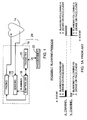
- a pacemaker 10 constructed in accordance with this invention includes a sensing circuit 12 receiving signals from the heart 14 of a patient and a pacing circuit 16 for generating pacing pulses for the heart 14.
- a controller 18, which is usually a digital microprocessor receives the signals from the sensor indicative of the electrical activity of the heart, and based on these signals, generates appropriate control signals for the pacing circuit 16.
- Pacemaker 10 further includes a telemetry device 20 for selectively exchanging information with an external programmer 22.
- the pacemaker 10 and programmer 22 jointly form a pacemaker system 24.
- the pacemaker in Figure 2 is adapted to operate in a DDDR mode and as such, it receives A-sense and V-sense signals and generates-A-pace and V-pace pulses.
- the controller 18 includes a pacer state machine 24 which generates the pace signals based on the sense signals.
- the A- and V-sense signals are also fed to a blanking period calculator 26 which calculates and stores the blanking periods and sends corresponding blanking period signals to the sensory circuit 12.
- the pacemaker state diagram is shown in Fig. 3. It should be understood that the invention is applicable to pacemakers operating in other modes as well.
- the PVARP is the Post Ventricular Atrial Refractory Period. An A-sense occurring during this interval is considered to be due to a retrogradely conducted ventricular event and is ignored. A V-sense occurring at any time starts the PVARP.
- the API which follows the PVARP is the Atrial Protection Interval and defines the minimum time between an ignored A-sense (i.e., in the PVARP) and the next A-pace.
- the API is intended to prevent an A-pace being provided during the vulnerable part of the atrial repolarization period, i.e., the relative refractory period during which arrhythmias may be induced.
- the Alert which may follow API, is the interval during which A-senses are classified to be P-waves (i.e., of sinus origin) within the correct rate range. Such P-waves are tracked 1:1 by the ventricular channel.
- the Alert is the remainder of W interval after the sum of the AV delay plus the PVARP plus the API.
- the AV delay which follows an atrial event is intended to mimic the natural P-wave to R-wave interval and is the time between an A-sense (or A-pace) and a V-pace (in the absence of a V-sense).
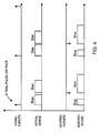
- the subject pacemaker further includes means for providing blanking periods in the various sensing channels during either atrial or ventricular activity. More particularly, as shown in Figure 4, every atrial event (i.e., atrial pace or atrial sense) is followed in the atrial sensing channel by a blanking period. Moreover blanking periods in the atrial sensing channel also follow each ventricular event to inhibit cross-channel noise.
- the blanking periods for atrial sensing following an atrial event are designated as Baa
- the ones following a ventricular event are designated Bav.
- the corresponding blanking periods for the ventricular channel are also shown in the Figure and are designated as Bvv and Bva, as shown.
- the present invention pertains to the means of determining and adjusting these blanking periods to insure that the sensing channels operate accurately and reliably.
- the pacemaker is provided with the blanking period calculator 26.
- the calculator 26 monitors the atrial and ventricular intracardiac signals and generates its own atrial and ventricular test blanking signals Bat, Bvt, respectively.
- the calculator 26 includes an atrial noise sensor 106 and a ventricular noise sensor 108. These sensors receive respectively the atrial and ventricular intracardiac signals as shown in Figure 1.
- the calculator 26 also includes an atrial pace command generator 102 and a ventricle pace command generator 104.
- the calculator 26 further includes individual determinator elements 110-116. The operation of the calculator 26 is now described in conjunction with the graphs of Figures 4 and 6 and the flow chart of Figure 7.
- the determination for the various blanking periods is made (or modified) in a physician's office with the patient' s pacemaker being coupled to the programmer 22 for initializing or modifying the pacemaker's operation.
- the programmer 22 provides the physicians with a sequence of steps that are performed to set up various programming parameters. As part of this procedure, the physician may measure and set the pacing signal threshold levels.
- the blanking periods may be determined and set at the same time as follows. Initially, as shown in Figure 7, in step S200 the atrium is overdrive paced by issuing appropriate pacing command to generator 102 using a fixed A-V delay of 200 msec. This step is performed to insure that the blanking periods are determined in response to atrial pacing and not an atrial natural pulse. It is believed that blanking periods following a paced pulse in either chamber should be longer than the blanking periods following an intrinsic cardiac event. Therefore, it is safe to apply the blanking periods determined for a paced event to a sensed (intrinsic) event.
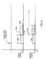
- an atrial test pace signal 300 is generated, as indicated on Figure 6 (Step 202).
- a shortened atrial test blanking signal Bat is generated by a test blanking generator 118 ( Figure 5) for the atrial sensing channel 25.
- a similar signal Bvt is generated by generator 118 for the ventricular sensing channel 34 (Fig. 6, Step 204, Fig. 7).
- These signals are selected to correspond to the time required for the sense amplifier in sensing circuit 12, sensors 106, 108 to settle. For example these test blanking periods may be in the order of 20-30 msec.
- the atrial noise sensor 106 starts monitoring the atrial intracardiac signal. As shown in Figure 6, typically a variable noise signal 302 is sensed in response to atrial test pace signal 300. Noise signal 302 sensed in the atrium decays after a time duration Tan at which time its peak falls below the sensor threshold level ATH. The output of atrial sensor 106 is fed to determinator 110 which also receives the Bat signal. Determinator 110 measures the time duration Tan by determining the last point in time when the atrial noise sensor receives an input exceeding ATH. This time duration Tan is characteristic of the tissues of heart and other factors.
- a corresponding blanking period Bvt is also generated for the ventricular sensor.
- this signal is also in the range of 20-30 msec.
- a noise signal 304 is detected by sensing circuit 12. This signal is sensed by ventricular noise sensor 108 and fed to the determinator circuit 114. Determinator circuit 114 also receives the Bvt signal. After a time period Tvn, the ventricular noise signal decays to a peak level below threshold VTH. In order to insure that the blanking period does not exceed the A-V interval, the period Tvn is limited to 80 msec (Tmax). The determinator 114 thus measures the length of signal Tvn.
- step S214 a test is conducted to determine if the difference between any two of the parameters Tan is greater than 20 msec. If this difference is less than 20 msec, than the longest Tan (longest) is selected.
- step S 216 the blanking period is then calculated or set by adding Bat + Tan (longest) + safety factor. For example the safety factor may be about 15 msec.
- the parameters Tvn(o...n) are analyzed similarly to determine in step S216 for the value Bav. These values are sent to the display of the programmer. (S218).
- step S214 If in step S214 it is determined that the difference between any two measurement Tan (j) exceeds 20 msec, then in step S220 an error message is sent to the programmer which in response (S222) displays a request that the whole procedure be repeated since the first set of values are unreliable.
- the ventricle is paced in a manner similar the one described above to obtain the values for Bva and Bvv.
- Baa, Bav, Bva, Bvv are transmitted to and displayed by the programmer in step S218. These values may be used as parameters by the pacemaker or may be used as suggested values to the physician as possible programmed values for blanking periods.
- Bva is not very important and has been included herein for the sake of completeness.
- the pacemaker 24 itself may set its own blanking periods to the values determined as described above.
- the atrial electrode 50 is connected to an amplifier 52.
- the output of amplifier 52 is fed to a comparator 54.
- the comparator compares the amplified signal sensed on line 50 with a programmable sensing threshold stored in a memory 56. Signals above this threshold are sent as an A-sense signals by the circuit 12.
- Sensor 106 includes a peak detector 58 which' detects the peaks of the signals senses on line 50. These peaks are fed to a comparator 60.
- the sensor 106 also includes a divide-by-two circuit 62 which receives the sensing threshold from memory 56 and divides by two.
- the comparator compares the signals on line 50 with the output of circuit 62 and generates an output when the peaks detected by detector 58 fall below this output. This signal is used to determine the Baa signal as discussed above.
- the threshold (ATH) may be detected at 50% or less than the programmed sensitivity stored in memory 56. The advantage of this approach is that it can automatically determine a high signal to noise ratio of about 2:1.
- the ideal or suggested blanking periods are determined by the pacemaker.
- Another alternative would be to perform the calculation on the programmer, using the main timing events (MTEs) only.
- MTEs are marker generated to indicate senses of intracardiac ECGs. In the case, MTEs are markers of noise senses following a paced event.
Abstract
Description
- This invention relates to single or dual chamber pacemakers, and more particularly to a mode of operation wherein one or more blanking periods are determined by measuring inherent noise propagation characteristics of the pacemaker system.
- In the following description, the term pacemaker refers to all implantable cardiac devices having cardiac pacing and sensing capabilities. Briefly, in these types of devices the sensed signals are fed to a sensing amplifier for amplification and signal conditioning.
- This sensing amplifier disables its sensing ability for a brief period following a sensed or a paced event. The time during which sensing is disabled is called a blanking period. The blanking period prevents inappropriate sensing of residual energy by the pacemaker amplifier following an intrinsic event or a pacemaker output pulse. The blanking period may be applied to the same chamber where the event occurs. In dual chamber pacemakers, the blanking period also may be applied to the chamber other than the one in which the event occurs. In this case, the blanking period is called the cross-channel blanking period. There are eight possible blanking periods (See Fig. 1A) in a pacemaker: (1) atrial blanking period after an atrial sense, (2) atrial blanking period after an atrial pace, (3) atrial blanking period after a ventricular sense, (4) atrial blanking period after a ventricular pace, (5) ventricular blanking period after an atrial sense, (6) ventricular blanking period after an atrial pace (7) ventricular blanking period after a ventricular sense, and (8) ventricular blanking period after a ventricular pace. The blanking period is a function of sensing/pacing polarity; sensitivity; pacing amplitude, pulse width, lead maturation, and position of leads. In general, in prior art devices, the durations of these blanking periods was either fixed at the factory, or was one of the adjustable programmer parameters that had to be set by the physician either based on average values obtained from statistical data, or by trial and error.
- It is advantageous to provide dual chamber pacemaker with an AMS (Automatic Mode Switching) function, as described for example, in U.S. Patent No. 5,441,523, incorporated herein by reference. The AMS function switches the pacemaker from a rate-response mode, wherein pacing rate is determined from a physiological pacemaker to a backup pacing rate under certain pre-selected conditions. However, in such a pacemaker an extra long atrial blanking period reduces the sensitivity of the AMS function. In the worst case situation the A-V delay may be equal to or shorter than the atrial blanking period following an atrial event (blanking periods (1) or (2)). Since the A-V delay is followed by a ventricular event, which in turn causes the atrial blanking period to extend still further by a cross channel blanking period (3) or (4). If an intrinsic R-wave occurs before the end of the A-V delay, the atrial blanking period is also extended by blanking period (3). Therefore, fast atrial events associated with atrial tachycardia such as atrial fibrillation or atrial flutter may occur during this extra long blanking period and cannot be sensed by the pacemaker. Accordingly the atrial tachycardia is not detected and the pacemaker does not activate the AMS function to switch from a dual chamber to a ventricular non-tracking mode.
- However, if the blanking periods are set to be too short, in channel or cross channel noise may be erroneously sensed as a cardiac event. For example for a short atrial blanking following a ventricular event, a farfield R wave may be sensed improperly as a new ventricular event.
- Similarly, if a cross channel ventricular blanking period (5 or 6) is too short, an atrial event may be erroneously interpreted as a ventricular event and ventricular pacing maybe inhibited. If the same ventricular blanking period is too long however, a premature ventricular contraction may occur during this blanking period and a proper A-V delay would not be set up.
- Thus, it is clear that the operation of a pacemaker would be vastly improved if the blanking periods can be set accurately and automatically to reflect and compensate for the electrical characteristics of a particular pacemaker system and/or the patient's tissues.
- An objective of the present invention is to provide a pacemaker in which the sensing blanking periods are optimized for a particular patient, pacemaker or both.
- A further objective is to provide a pacemaker system in which the blanking periods are determined automatically.
- A further objective is to provide a pacemaker system capable of calculating both the in channel and cross channel blanking periods.
- Other objectives and advantages of the invention shall become apparent from the following description.
- Briefly, a pacemaker system constructed in accordance with this invention includes a pacemaker having means for generating test pulses to a cardiac chamber, and means for sensing cardiac signals corresponding to said pulses, after a preset time period. The time period required for said cardiac signals to decay is measured and this period is used to determine the duration of the in-channel and/or cross channel blanking periods for the pacemaker.
- Alternatively, the duration of the blanking periods is determined externally in which case the cardiac response to other stimulation is used as a criteria.
- Further objects, features and advantages of the invention will become apparent upon consideration of the following description, taken in conjunction with the accompanying drawing, in which:
- Fig. 1A shows the blanking periods in a prior art dual chamber pacemaker;
- Fig. 1 is a block diagram of a pacemaker which embodies the subject invention;
- Fig. 2 is a block diagram of the controller of Fig. 1;
- Fig. 3 is a state diagram that characterizes the operation of the pacemaker of Fig. 1;
- Fig. 4 is a timing diagram showing the relationship between pacing pulses and the corresponding blanking periods in accordance with this invention;
- Fig. 5 shows a circuit used to determine the blanking periods in accordance with this invention;
- Fig. 6 shows a timing diagram for the circuit of Fig. 5;
- Fig. 7 shows a flow chart for the circuit of Fig. 5; and
- Fig. 8 shows details of a determinator circuit.
- Referring now to Figure 1, a
pacemaker 10 constructed in accordance with this invention includes asensing circuit 12 receiving signals from theheart 14 of a patient and apacing circuit 16 for generating pacing pulses for theheart 14. Acontroller 18, which is usually a digital microprocessor receives the signals from the sensor indicative of the electrical activity of the heart, and based on these signals, generates appropriate control signals for thepacing circuit 16. - Pacemaker 10 further includes a
telemetry device 20 for selectively exchanging information with anexternal programmer 22. Thepacemaker 10 andprogrammer 22 jointly form apacemaker system 24. - Although the invention may be applicable to other types of pacemakers, the pacemaker in Figure 2 is adapted to operate in a DDDR mode and as such, it receives A-sense and V-sense signals and generates-A-pace and V-pace pulses. As shown in more detail in Figure 2, the
controller 18 includes apacer state machine 24 which generates the pace signals based on the sense signals. In addition, the A- and V-sense signals are also fed to ablanking period calculator 26 which calculates and stores the blanking periods and sends corresponding blanking period signals to thesensory circuit 12. - A preferred embodiment the pacemaker state diagram is shown in Fig. 3. It should be understood that the invention is applicable to pacemakers operating in other modes as well. The PVARP is the Post Ventricular Atrial Refractory Period. An A-sense occurring during this interval is considered to be due to a retrogradely conducted ventricular event and is ignored. A V-sense occurring at any time starts the PVARP.
- The API which follows the PVARP is the Atrial Protection Interval and defines the minimum time between an ignored A-sense (i.e., in the PVARP) and the next A-pace. The API is intended to prevent an A-pace being provided during the vulnerable part of the atrial repolarization period, i.e., the relative refractory period during which arrhythmias may be induced.
- The Alert which may follow API, is the interval during which A-senses are classified to be P-waves (i.e., of sinus origin) within the correct rate range. Such P-waves are tracked 1:1 by the ventricular channel. The Alert is the remainder of W interval after the sum of the AV delay plus the PVARP plus the API.
- The AV delay which follows an atrial event is intended to mimic the natural P-wave to R-wave interval and is the time between an A-sense (or A-pace) and a V-pace (in the absence of a V-sense).
- Importantly, the subject pacemaker further includes means for providing blanking periods in the various sensing channels during either atrial or ventricular activity. More particularly, as shown in Figure 4, every atrial event (i.e., atrial pace or atrial sense) is followed in the atrial sensing channel by a blanking period. Moreover blanking periods in the atrial sensing channel also follow each ventricular event to inhibit cross-channel noise. In Figure 4 the blanking periods for atrial sensing following an atrial event are designated as Baa, and the ones following a ventricular event are designated Bav. The corresponding blanking periods for the ventricular channel are also shown in the Figure and are designated as Bvv and Bva, as shown.
- As previously described, the present invention pertains to the means of determining and adjusting these blanking periods to insure that the sensing channels operate accurately and reliably. In order to determine these blanking periods, the pacemaker is provided with the
blanking period calculator 26. As shown in detail in Figure 5, thecalculator 26 monitors the atrial and ventricular intracardiac signals and generates its own atrial and ventricular test blanking signals Bat, Bvt, respectively. - The
calculator 26 includes anatrial noise sensor 106 and aventricular noise sensor 108. These sensors receive respectively the atrial and ventricular intracardiac signals as shown in Figure 1. Thecalculator 26 also includes an atrialpace command generator 102 and a ventriclepace command generator 104. Thecalculator 26 further includes individual determinator elements 110-116. The operation of thecalculator 26 is now described in conjunction with the graphs of Figures 4 and 6 and the flow chart of Figure 7. - Preferably the determination for the various blanking periods is made (or modified) in a physician's office with the patient' s pacemaker being coupled to the
programmer 22 for initializing or modifying the pacemaker's operation. Theprogrammer 22 provides the physicians with a sequence of steps that are performed to set up various programming parameters. As part of this procedure, the physician may measure and set the pacing signal threshold levels. The blanking periods may be determined and set at the same time as follows. Initially, as shown in Figure 7, in step S200 the atrium is overdrive paced by issuing appropriate pacing command togenerator 102 using a fixed A-V delay of 200 msec. This step is performed to insure that the blanking periods are determined in response to atrial pacing and not an atrial natural pulse. It is believed that blanking periods following a paced pulse in either chamber should be longer than the blanking periods following an intrinsic cardiac event. Therefore, it is safe to apply the blanking periods determined for a paced event to a sensed (intrinsic) event. - Next an atrial test pace signal 300 is generated, as indicated on Figure 6 (Step 202). Following this signal 300, a shortened atrial test blanking signal Bat is generated by a test blanking generator 118 (Figure 5) for the atrial sensing channel 25. A similar signal Bvt is generated by
generator 118 for the ventricular sensing channel 34 (Fig. 6, Step 204, Fig. 7). These signals are selected to correspond to the time required for the sense amplifier insensing circuit 12,sensors - Following the test blanking signal Bat, the
atrial noise sensor 106 starts monitoring the atrial intracardiac signal. As shown in Figure 6, typically avariable noise signal 302 is sensed in response to atrial test pace signal 300.Noise signal 302 sensed in the atrium decays after a time duration Tan at which time its peak falls below the sensor threshold level ATH. The output ofatrial sensor 106 is fed todeterminator 110 which also receives the Bat signal.Determinator 110 measures the time duration Tan by determining the last point in time when the atrial noise sensor receives an input exceeding ATH. This time duration Tan is characteristic of the tissues of heart and other factors. - As shown in Figure 6, concurrently with the blanking period Bat, a corresponding blanking period Bvt is also generated for the ventricular sensor. Preferably this signal is also in the range of 20-30 msec. At the end of this period, a noise signal 304 is detected by sensing
circuit 12. This signal is sensed byventricular noise sensor 108 and fed to thedeterminator circuit 114.Determinator circuit 114 also receives the Bvt signal. After a time period Tvn, the ventricular noise signal decays to a peak level below threshold VTH. In order to insure that the blanking period does not exceed the A-V interval, the period Tvn is limited to 80 msec (Tmax). Thedeterminator 114 thus measures the length of signal Tvn. - As shown on Figure 7, after the signals Tan (i), Tvn (i) are measured, the whole cycle is repeated several times until several values Tan(n), Tvn (n) are obtained. The value of 'n' may be for example two. This is illustrated in Figure 7 by steps S206, S208, S210. At this point, the parameters Tan(n), Tvn(0 ...n) are analyzed to determine the maximum difference between the respective values. In step S214 a test is conducted to determine if the difference between any two of the parameters Tan is greater than 20 msec. If this difference is less than 20 msec, than the longest Tan (longest) is selected. In step S 216 the blanking period is then calculated or set by adding Bat + Tan (longest) + safety factor. For example the safety factor may be about 15 msec. The parameters Tvn(o...n) are analyzed similarly to determine in step S216 for the value Bav. These values are sent to the display of the programmer. (S218).
- If in step S214 it is determined that the difference between any two measurement Tan (j) exceeds 20 msec, then in step S220 an error message is sent to the programmer which in response (S222) displays a request that the whole procedure be repeated since the first set of values are unreliable.
- After the blanking periods Baa, and Bav are calculated as described above, the ventricle is paced in a manner similar the one described above to obtain the values for Bva and Bvv.
- The value of Baa, Bav, Bva, Bvv are transmitted to and displayed by the programmer in step S218. These values may be used as parameters by the pacemaker or may be used as suggested values to the physician as possible programmed values for blanking periods. The value of Bva is not very important and has been included herein for the sake of completeness.
- Alternatively, the
pacemaker 24 itself may set its own blanking periods to the values determined as described above. - Typically, as shown in Figure 8, in the sensing circuit for sensing the atrium, the
atrial electrode 50 is connected to anamplifier 52. The output ofamplifier 52 is fed to acomparator 54. The comparator compares the amplified signal sensed online 50 with a programmable sensing threshold stored in amemory 56. Signals above this threshold are sent as an A-sense signals by thecircuit 12.Sensor 106 includes apeak detector 58 which' detects the peaks of the signals senses online 50. These peaks are fed to acomparator 60. Thesensor 106 also includes a divide-by-twocircuit 62 which receives the sensing threshold frommemory 56 and divides by two. The comparator compares the signals online 50 with the output ofcircuit 62 and generates an output when the peaks detected bydetector 58 fall below this output. This signal is used to determine the Baa signal as discussed above. The threshold (ATH) may be detected at 50% or less than the programmed sensitivity stored inmemory 56. The advantage of this approach is that it can automatically determine a high signal to noise ratio of about 2:1. - In the embodiment described above, the ideal or suggested blanking periods are determined by the pacemaker. Alternatively, the calculation to determine the blanking period in the programmer using telemetered ECG's obtained by the pacemaker. Another alternative would be to perform the calculation on the programmer, using the main timing events (MTEs) only. MTEs are marker generated to indicate senses of intracardiac ECGs. In the case, MTEs are markers of noise senses following a paced event.
- Although the invention has been described with reference to several particular embodiments, it is to be understood that these embodiments are merely illustrative of the application of the principles of the invention. Accordingly, the embodiments described in particular should be considered exemplary, not limiting, with respect to the following claims.
Claims (19)
- A cardiac stimulation system comprising:pacing means for generating cardiac pacing signals of a patient;sensing means for sensing cardiac activity in a cardiac chamber, said sensing means generating sense signals corresponding said cardiac activity;signal processing means for processing said sense signals;blanking signal generating means for generating blanking signals, said blanking signals being provided for selectively blanking said signal processing means; andautomatic blanking determining means for determining a minimum duration of said blanking signals dependent on physiological characteristics of said heart.
- A system according to claim 1 further comprising an implantable cardiac device, said automatic blanking determining means is disposed in said implantable device.
- A system according to claim 1 or 2 wherein said blanking means includes means for generating a test pacing signal for said heart and test sensing means for sensing activity in said heart responsive to said test pacing signal.
- A system according to claim 3 wherein said automatic blanking determining means includes amplitude sensing means for measuring a period from said test pacing signal until said activity falls below a threshold, said determining means selecting a first blanking signal based on said period.
- A system according to claim 4 wherein said test pacing signal is delivered in a first cardiac chamber and said activity is sensed in a second cardiac chamber to determine a first cross-channel blanking signal.
- A system according to claim 4 wherein said test pacing signal is delivered in a first cardiac chamber and said activity is sensed in said first cardiac chamber to determine a first in-channel blanking period.
- An implantable cardiac device for implantation in a patient for stimulating the patient's heart, comprising:pacing means for generating pacing pulses for a first cardiac chamber;sensing means for sensing cardiac activity in said heart;blanking means for blanking said sensing means for at least a blanking period following said cardiac activity;determining means for determining a duration of said blanking period based on a physiology of said heart.
- A device according to claim 7 wherein said determining means generates a test signal in said first chamber, measures a response to said test signal and determines said duration in accordance with said response.
- A device according to claim 8 wherein said determining means measures said response in said first chamber to determine an in-channel blanking period.
- A device according to claim 8 or 9 wherein said first chamber is the atrium.
- A device according to claim 8 or 9 wherein said first chamber is the ventricle.
- A device according to any one of claims 8 to 11 wherein said determining means measures said response in a second chamber to determine a cross channel blanking period.
- A device according to any one of claims 8 to 12 wherein said determining means includes detecting means for detecting a peak of said activity.
- A device according to claim 13 wherein said duration extends from said test signal to a time when said peak falls below a threshold.
- A device according to claim 14 wherein said threshold is a fraction of a maximum peak of said activity.
- A device according to any one of claims 8 to 15 wherein said blanking period is set by incrementing said duration a preselected safety margin.
- A device according to claim 16 wherein said safety margin is about 10-30 ms.
- A device according to claim 16 or 17 wherein said blanking period is limited to a preselected maximum value.
- A device according to any one of claims 8 to 18 wherein said duration is provided to an external programmer used to program said device.
Applications Claiming Priority (2)
| Application Number | Priority Date | Filing Date | Title |
|---|---|---|---|
| US560733 | 1995-11-20 | ||
| US08/560,733 US5591214A (en) | 1995-11-20 | 1995-11-20 | Pacemaker with automatic blanking period function |
Publications (3)
| Publication Number | Publication Date |
|---|---|
| EP0774274A2 true EP0774274A2 (en) | 1997-05-21 |
| EP0774274A3 EP0774274A3 (en) | 1998-10-28 |
| EP0774274B1 EP0774274B1 (en) | 2004-07-07 |
Family
ID=24239134
Family Applications (1)
| Application Number | Title | Priority Date | Filing Date |
|---|---|---|---|
| EP96307824A Expired - Lifetime EP0774274B1 (en) | 1995-11-20 | 1996-10-29 | Pacemaker with automatic blanking period function |
Country Status (3)
| Country | Link |
|---|---|
| US (1) | US5591214A (en) |
| EP (1) | EP0774274B1 (en) |
| DE (1) | DE69632853T2 (en) |
Families Citing this family (146)
| Publication number | Priority date | Publication date | Assignee | Title |
|---|---|---|---|---|
| US5776167A (en) * | 1996-02-27 | 1998-07-07 | Pacesetter, Inc. | System and method for alleviating the effects of pacemaker crosstalk |
| US6415180B1 (en) | 1997-04-04 | 2002-07-02 | Cardiac Pacemakers, Inc. | Device and method for ventricular tracking and pacing |
| US5817136A (en) * | 1997-05-02 | 1998-10-06 | Pacesetter, Inc. | Rate-responsive pacemaker with minute volume determination and EMI protection |
| US5978713A (en) * | 1998-02-06 | 1999-11-02 | Intermedics Inc. | Implantable device with digital waveform telemetry |
| US6128533A (en) * | 1999-03-22 | 2000-10-03 | Pacesetter, Inc. | Pacemaker with automatic PVARP adjustment during automatic mode switching |
| US6718198B2 (en) | 1999-08-24 | 2004-04-06 | Cardiac Pacemakers, Inc. | Arrhythmia display |
| US6304778B1 (en) * | 1999-08-20 | 2001-10-16 | Cardiac Pacemakers, Inc. | Implantable defibrillators with programmable cross-chamber blanking |
| US6535763B1 (en) | 1999-08-22 | 2003-03-18 | Cardia Pacemakers, Inc. | Event marker alignment by inclusion of event marker transmission latency in the real-time data stream |
| US6477416B1 (en) * | 2000-05-15 | 2002-11-05 | Pacesetter, Inc. | System and method for automatically and adaptively segmenting an atrial blanking period |
| US7801606B2 (en) | 2000-08-29 | 2010-09-21 | Cardiac Pacemakers, Inc. | Implantable pulse generator and method having adjustable signal blanking |
| US8548576B2 (en) | 2000-12-15 | 2013-10-01 | Cardiac Pacemakers, Inc. | System and method for correlation of patient health information and implant device data |
| US6665558B2 (en) * | 2000-12-15 | 2003-12-16 | Cardiac Pacemakers, Inc. | System and method for correlation of patient health information and implant device data |
| US7245966B2 (en) | 2000-12-21 | 2007-07-17 | Medtronic, Inc. | Ventricular event filtering for an implantable medical device |
| US7738955B2 (en) * | 2000-12-21 | 2010-06-15 | Medtronic, Inc. | System and method for ventricular pacing with AV interval modulation |
| US9931509B2 (en) | 2000-12-21 | 2018-04-03 | Medtronic, Inc. | Fully inhibited dual chamber pacing mode |
| US6553258B2 (en) * | 2000-12-26 | 2003-04-22 | Cardiac Pacemakers, Inc. | System and method for managing refractory periods in a cardiac rhythm management device with biventricular sensing |
| US6643547B2 (en) | 2001-03-30 | 2003-11-04 | Cardiac Pacemakers, Inc. | Method and device for sensing atrial depolarizations during ventricular tachycardia |
| US6819955B2 (en) | 2001-10-09 | 2004-11-16 | Pacesetter, Inc. | Multi-chamber ventricular automatic capture method and apparatus for minimizing true and blanking period induced ventricular undersensing |
| US6892092B2 (en) * | 2001-10-29 | 2005-05-10 | Cardiac Pacemakers, Inc. | Cardiac rhythm management system with noise detector utilizing a hysteresis providing threshold |
| US7215993B2 (en) * | 2002-08-06 | 2007-05-08 | Cardiac Pacemakers, Inc. | Cardiac rhythm management systems and methods for detecting or validating cardiac beats in the presence of noise |
| US6917830B2 (en) * | 2001-10-29 | 2005-07-12 | Cardiac Pacemakers, Inc. | Method and system for noise measurement in an implantable cardiac device |
| US6625490B1 (en) | 2001-11-14 | 2003-09-23 | Pacesetter, Inc. | System and method of automatically adjusting sensing parameters based on temporal measurement of cardiac events |
| US6650931B1 (en) | 2001-11-14 | 2003-11-18 | Pacesetter, Inc. | System and method of automatically determining the onsets and ends of cardiac events and far-field signals |
| SE0300916D0 (en) | 2003-03-31 | 2003-03-31 | St Jude Medical | Multi-chamber pacing system |
| SE0300917D0 (en) * | 2003-03-31 | 2003-03-31 | St Jude Medical | Multi-chamber pacing system |
| US7062328B1 (en) | 2003-08-25 | 2006-06-13 | Pacesetter, Inc. | System and method for providing improved specificity for automatic mode switching within an implantable medical device |
| US7286872B2 (en) * | 2003-10-07 | 2007-10-23 | Cardiac Pacemakers, Inc. | Method and apparatus for managing data from multiple sensing channels |
| US7174210B1 (en) | 2003-12-05 | 2007-02-06 | Pacesetter, Inc. | Method and apparatus for improving specificity of atrial tachycardia detection techniques in dual-unipolar or dual-bipolar implantable cardiac stimulation systems |
| US7158829B1 (en) | 2003-12-05 | 2007-01-02 | Pacesetter, Inc. | Method and apparatus for improving specificity of atrial tachycardia detection techniques in dual-unipolar or dual-bipolar implantable cardiac stimulation systems |
| US7184834B1 (en) | 2003-12-05 | 2007-02-27 | Pacesetter, Inc. | Method and apparatus for improving specificity of atrial tachycardia detection techniques in dual-unipolar or dual-bipolar implantable cardiac stimulation systems |
| US7146213B1 (en) | 2003-12-05 | 2006-12-05 | Pacesetter, Inc. | Method and apparatus for improving specificity of atrial tachycardia detection techniques in dual-unipolar or dual-bipolar implantable cardiac stimulation systems |
| US7471980B2 (en) * | 2003-12-22 | 2008-12-30 | Cardiac Pacemakers, Inc. | Synchronizing continuous signals and discrete events for an implantable medical device |
| US7437190B1 (en) | 2004-03-02 | 2008-10-14 | Pacesetter, Inc. | Cardiac stimulation device with adjustable blanking intervals |
| US7398123B1 (en) | 2004-03-05 | 2008-07-08 | Pacesetter, Inc. | Methods and devices for reducing the detection of inappropriate physiologic signals to reduce misdiagnosis of normal rhythms as tachyarrhythmias |
| US7616994B2 (en) * | 2004-05-24 | 2009-11-10 | Cardiac Pacemakers, Inc. | Fast post-antitachycardia pacing redetection algorithm |
| US7774112B2 (en) | 2004-09-27 | 2010-08-10 | Teledyne Technologies Incorporated | System and method for flight data recording |
| US7248924B2 (en) * | 2004-10-25 | 2007-07-24 | Medtronic, Inc. | Self limited rate response |
| US7593773B2 (en) * | 2005-01-21 | 2009-09-22 | Medtronic, Inc. | Implantable medical device with ventricular pacing protocol including progressive conduction search |
| US7542799B2 (en) * | 2005-01-21 | 2009-06-02 | Medtronic, Inc. | Implantable medical device with ventricular pacing protocol |
| US8046060B2 (en) | 2005-11-14 | 2011-10-25 | Cardiac Pacemakers, Inc. | Differentiating arrhythmic events having different origins |
| US7925344B2 (en) | 2006-01-20 | 2011-04-12 | Medtronic, Inc. | System and method of using AV conduction timing |
| US8046063B2 (en) * | 2006-02-28 | 2011-10-25 | Medtronic, Inc. | Implantable medical device with adaptive operation |
| US7894898B2 (en) * | 2006-06-15 | 2011-02-22 | Medtronic, Inc. | System and method for ventricular interval smoothing following a premature ventricular contraction |
| US7783350B2 (en) * | 2006-06-15 | 2010-08-24 | Medtronic, Inc. | System and method for promoting intrinsic conduction through atrial timing modification and calculation of timing parameters |
| US7565196B2 (en) * | 2006-06-15 | 2009-07-21 | Medtronic, Inc. | System and method for promoting intrinsic conduction through atrial timing |
| US7869872B2 (en) * | 2006-06-15 | 2011-01-11 | Medtronic, Inc. | System and method for determining intrinsic AV interval timing |
| US7515958B2 (en) | 2006-07-31 | 2009-04-07 | Medtronic, Inc. | System and method for altering pacing modality |
| US7715914B2 (en) * | 2006-07-31 | 2010-05-11 | Medtronic, Inc. | System and method for improving ventricular sensing |
| US7689281B2 (en) | 2006-07-31 | 2010-03-30 | Medtronic, Inc. | Pacing mode event classification with increased ventricular sensing |
| US7502646B2 (en) * | 2006-07-31 | 2009-03-10 | Medtronic, Inc. | Pacing mode event classification with rate smoothing and increased ventricular sensing |
| US7502647B2 (en) * | 2006-07-31 | 2009-03-10 | Medtronic, Inc. | Rate smoothing pacing modality with increased ventricular sensing |
| US7856269B2 (en) | 2006-07-31 | 2010-12-21 | Medtronic, Inc. | System and method for determining phsyiologic events during pacing mode operation |
| US7720537B2 (en) | 2006-07-31 | 2010-05-18 | Medtronic, Inc. | System and method for providing improved atrial pacing based on physiological need |
| US8233980B2 (en) * | 2008-05-07 | 2012-07-31 | Pacesetter, Inc. | System and method for detecting hidden atrial events for use with automatic mode switching within an implantable medical device |
| US20090281588A1 (en) * | 2008-05-09 | 2009-11-12 | Pacesetter, Inc. | Determining atrial time periods in conjunction with real-time testing |
| US8126550B2 (en) * | 2008-07-22 | 2012-02-28 | Pacesetter, Inc. | Methods and devices involving automatic atrial blanking |
| US8244354B2 (en) * | 2009-02-27 | 2012-08-14 | Medtronic, Inc. | System and method for conditional biventricular pacing |
| EP2403593B1 (en) * | 2009-02-27 | 2014-04-09 | Medtronic, Inc | System for conditional biventricular pacing |
| WO2010099424A1 (en) * | 2009-02-27 | 2010-09-02 | Medtronic, Inc. | A system and method for conditional biventricular pacing |
| US8447400B2 (en) | 2010-06-24 | 2013-05-21 | Pacesetter, Inc. | Systems and methods for use by an implantable medical device for controlling multi-site CRT pacing in the presence of atrial tachycardia |
| US8332033B2 (en) | 2010-06-24 | 2012-12-11 | Pacesetter, Inc. | Systems and methods for use by an implantable medical device for controlling multi-site CRT pacing in the presence of atrial tachycardia |
| AU2015204701B2 (en) | 2014-01-10 | 2018-03-15 | Cardiac Pacemakers, Inc. | Systems and methods for detecting cardiac arrhythmias |
| WO2015106007A1 (en) | 2014-01-10 | 2015-07-16 | Cardiac Pacemakers, Inc. | Methods and systems for improved communication between medical devices |
| US9757570B2 (en) * | 2014-08-06 | 2017-09-12 | Cardiac Pacemakers, Inc. | Communications in a medical device system |
| WO2016033197A2 (en) | 2014-08-28 | 2016-03-03 | Cardiac Pacemakers, Inc. | Medical device with triggered blanking period |
| WO2016126613A1 (en) | 2015-02-06 | 2016-08-11 | Cardiac Pacemakers, Inc. | Systems and methods for treating cardiac arrhythmias |
| US10220213B2 (en) | 2015-02-06 | 2019-03-05 | Cardiac Pacemakers, Inc. | Systems and methods for safe delivery of electrical stimulation therapy |
| WO2016130477A2 (en) | 2015-02-09 | 2016-08-18 | Cardiac Pacemakers, Inc. | Implantable medical device with radiopaque id tag |
| WO2016141046A1 (en) | 2015-03-04 | 2016-09-09 | Cardiac Pacemakers, Inc. | Systems and methods for treating cardiac arrhythmias |
| US10050700B2 (en) | 2015-03-18 | 2018-08-14 | Cardiac Pacemakers, Inc. | Communications in a medical device system with temporal optimization |
| CN107427222B (en) | 2015-03-18 | 2021-02-09 | 心脏起搏器股份公司 | Communication in a medical device system using link quality assessment |
| CN108136186B (en) | 2015-08-20 | 2021-09-17 | 心脏起搏器股份公司 | System and method for communication between medical devices |
| EP3337559B1 (en) | 2015-08-20 | 2019-10-16 | Cardiac Pacemakers, Inc. | Systems and methods for communication between medical devices |
| US9956414B2 (en) | 2015-08-27 | 2018-05-01 | Cardiac Pacemakers, Inc. | Temporal configuration of a motion sensor in an implantable medical device |
| US9968787B2 (en) | 2015-08-27 | 2018-05-15 | Cardiac Pacemakers, Inc. | Spatial configuration of a motion sensor in an implantable medical device |
| WO2017040153A1 (en) | 2015-08-28 | 2017-03-09 | Cardiac Pacemakers, Inc. | Systems and methods for behaviorally responsive signal detection and therapy delivery |
| WO2017040115A1 (en) | 2015-08-28 | 2017-03-09 | Cardiac Pacemakers, Inc. | System for detecting tamponade |
| US10226631B2 (en) | 2015-08-28 | 2019-03-12 | Cardiac Pacemakers, Inc. | Systems and methods for infarct detection |
| WO2017044389A1 (en) | 2015-09-11 | 2017-03-16 | Cardiac Pacemakers, Inc. | Arrhythmia detection and confirmation |
| CN108136185B (en) | 2015-10-08 | 2021-08-31 | 心脏起搏器股份公司 | Apparatus and method for adjusting pacing rate in an implantable medical device |
| WO2017106693A1 (en) | 2015-12-17 | 2017-06-22 | Cardiac Pacemakers, Inc. | Conducted communication in a medical device system |
| US10905886B2 (en) | 2015-12-28 | 2021-02-02 | Cardiac Pacemakers, Inc. | Implantable medical device for deployment across the atrioventricular septum |
| WO2017127548A1 (en) | 2016-01-19 | 2017-07-27 | Cardiac Pacemakers, Inc. | Devices for wirelessly recharging a rechargeable battery of an implantable medical device |
| US10350423B2 (en) | 2016-02-04 | 2019-07-16 | Cardiac Pacemakers, Inc. | Delivery system with force sensor for leadless cardiac device |
| US11116988B2 (en) | 2016-03-31 | 2021-09-14 | Cardiac Pacemakers, Inc. | Implantable medical device with rechargeable battery |
| US10668294B2 (en) | 2016-05-10 | 2020-06-02 | Cardiac Pacemakers, Inc. | Leadless cardiac pacemaker configured for over the wire delivery |
| US10328272B2 (en) | 2016-05-10 | 2019-06-25 | Cardiac Pacemakers, Inc. | Retrievability for implantable medical devices |
| WO2018005373A1 (en) | 2016-06-27 | 2018-01-04 | Cardiac Pacemakers, Inc. | Cardiac therapy system using subcutaneously sensed p-waves for resynchronization pacing management |
| US11207527B2 (en) | 2016-07-06 | 2021-12-28 | Cardiac Pacemakers, Inc. | Method and system for determining an atrial contraction timing fiducial in a leadless cardiac pacemaker system |
| US10426962B2 (en) | 2016-07-07 | 2019-10-01 | Cardiac Pacemakers, Inc. | Leadless pacemaker using pressure measurements for pacing capture verification |
| US10688304B2 (en) | 2016-07-20 | 2020-06-23 | Cardiac Pacemakers, Inc. | Method and system for utilizing an atrial contraction timing fiducial in a leadless cardiac pacemaker system |
| WO2018035343A1 (en) | 2016-08-19 | 2018-02-22 | Cardiac Pacemakers, Inc. | Trans septal implantable medical device |
| CN109641129B (en) | 2016-08-24 | 2023-06-30 | 心脏起搏器股份公司 | Cardiac resynchronization with timing management using fusion facilitation |
| WO2018039335A1 (en) | 2016-08-24 | 2018-03-01 | Cardiac Pacemakers, Inc. | Integrated multi-device cardiac resynchronization therapy using p-wave to pace timing |
| US10994145B2 (en) | 2016-09-21 | 2021-05-04 | Cardiac Pacemakers, Inc. | Implantable cardiac monitor |
| US10758737B2 (en) | 2016-09-21 | 2020-09-01 | Cardiac Pacemakers, Inc. | Using sensor data from an intracardially implanted medical device to influence operation of an extracardially implantable cardioverter |
| WO2018057318A1 (en) | 2016-09-21 | 2018-03-29 | Cardiac Pacemakers, Inc. | Leadless stimulation device with a housing that houses internal components of the leadless stimulation device and functions as the battery case and a terminal of an internal battery |
| WO2018081275A1 (en) | 2016-10-27 | 2018-05-03 | Cardiac Pacemakers, Inc. | Multi-device cardiac resynchronization therapy with timing enhancements |
| AU2017350759B2 (en) | 2016-10-27 | 2019-10-17 | Cardiac Pacemakers, Inc. | Implantable medical device with pressure sensor |
| US10561330B2 (en) | 2016-10-27 | 2020-02-18 | Cardiac Pacemakers, Inc. | Implantable medical device having a sense channel with performance adjustment |
| EP3532159B1 (en) | 2016-10-27 | 2021-12-22 | Cardiac Pacemakers, Inc. | Implantable medical device delivery system with integrated sensor |
| WO2018081237A1 (en) | 2016-10-27 | 2018-05-03 | Cardiac Pacemakers, Inc. | Use of a separate device in managing the pace pulse energy of a cardiac pacemaker |
| US10413733B2 (en) | 2016-10-27 | 2019-09-17 | Cardiac Pacemakers, Inc. | Implantable medical device with gyroscope |
| US10434317B2 (en) | 2016-10-31 | 2019-10-08 | Cardiac Pacemakers, Inc. | Systems and methods for activity level pacing |
| CN109890456B (en) | 2016-10-31 | 2023-06-13 | 心脏起搏器股份公司 | System for activity level pacing |
| WO2018089311A1 (en) | 2016-11-08 | 2018-05-17 | Cardiac Pacemakers, Inc | Implantable medical device for atrial deployment |
| CN109952129B (en) | 2016-11-09 | 2024-02-20 | 心脏起搏器股份公司 | System, device and method for setting cardiac pacing pulse parameters for a cardiac pacing device |
| US10894163B2 (en) | 2016-11-21 | 2021-01-19 | Cardiac Pacemakers, Inc. | LCP based predictive timing for cardiac resynchronization |
| US10639486B2 (en) | 2016-11-21 | 2020-05-05 | Cardiac Pacemakers, Inc. | Implantable medical device with recharge coil |
| US10881869B2 (en) | 2016-11-21 | 2021-01-05 | Cardiac Pacemakers, Inc. | Wireless re-charge of an implantable medical device |
| EP3541473B1 (en) | 2016-11-21 | 2020-11-11 | Cardiac Pacemakers, Inc. | Leadless cardiac pacemaker with multimode communication |
| JP6843240B2 (en) | 2016-11-21 | 2021-03-17 | カーディアック ペースメイカーズ, インコーポレイテッド | Implantable medical device with permeable housing and induction coil placed around the housing |
| US11207532B2 (en) | 2017-01-04 | 2021-12-28 | Cardiac Pacemakers, Inc. | Dynamic sensing updates using postural input in a multiple device cardiac rhythm management system |
| WO2018140617A1 (en) | 2017-01-26 | 2018-08-02 | Cardiac Pacemakers, Inc. | Intra-body device communication with redundant message transmission |
| CN110198759B (en) | 2017-01-26 | 2023-08-11 | 心脏起搏器股份公司 | Leadless implantable device with removable fasteners |
| EP3573709A1 (en) | 2017-01-26 | 2019-12-04 | Cardiac Pacemakers, Inc. | Leadless device with overmolded components |
| US10905872B2 (en) | 2017-04-03 | 2021-02-02 | Cardiac Pacemakers, Inc. | Implantable medical device with a movable electrode biased toward an extended position |
| AU2018248361B2 (en) | 2017-04-03 | 2020-08-27 | Cardiac Pacemakers, Inc. | Cardiac pacemaker with pacing pulse energy adjustment based on sensed heart rate |
| US10918875B2 (en) | 2017-08-18 | 2021-02-16 | Cardiac Pacemakers, Inc. | Implantable medical device with a flux concentrator and a receiving coil disposed about the flux concentrator |
| US11065459B2 (en) | 2017-08-18 | 2021-07-20 | Cardiac Pacemakers, Inc. | Implantable medical device with pressure sensor |
| CN111107899B (en) | 2017-09-20 | 2024-04-02 | 心脏起搏器股份公司 | Implantable medical device with multiple modes of operation |
| US11185703B2 (en) | 2017-11-07 | 2021-11-30 | Cardiac Pacemakers, Inc. | Leadless cardiac pacemaker for bundle of his pacing |
| US11213684B2 (en) | 2017-11-29 | 2022-01-04 | Medtronic, Inc. | Device and method to reduce artifact from tissue conduction communication transmission |
| EP3717061B1 (en) | 2017-11-29 | 2021-12-29 | Medtronic, Inc. | Tissue conduction communication using ramped drive signal |
| WO2019108581A1 (en) | 2017-11-29 | 2019-06-06 | Medtronic, Inc. | Signal transmission optimization for tissue conduction communication |
| CN111417430B (en) | 2017-11-29 | 2024-03-08 | 美敦力公司 | Tissue conduction communication between devices |
| US11071870B2 (en) | 2017-12-01 | 2021-07-27 | Cardiac Pacemakers, Inc. | Methods and systems for detecting atrial contraction timing fiducials and determining a cardiac interval from a ventricularly implanted leadless cardiac pacemaker |
| EP3717064B1 (en) | 2017-12-01 | 2023-06-07 | Cardiac Pacemakers, Inc. | Methods and systems for detecting atrial contraction timing fiducials during ventricular filling from a ventricularly implanted leadless cardiac pacemaker |
| EP3717059A1 (en) | 2017-12-01 | 2020-10-07 | Cardiac Pacemakers, Inc. | Methods and systems for detecting atrial contraction timing fiducials within a search window from a ventricularly implanted leadless cardiac pacemaker |
| EP3717060B1 (en) | 2017-12-01 | 2022-10-05 | Cardiac Pacemakers, Inc. | Leadless cardiac pacemaker with reversionary behavior |
| EP3723848B1 (en) | 2017-12-15 | 2022-03-30 | Medtronic, Inc. | Device and method with adaptive timing for tissue conduction communication transmission |
| US11529523B2 (en) | 2018-01-04 | 2022-12-20 | Cardiac Pacemakers, Inc. | Handheld bridge device for providing a communication bridge between an implanted medical device and a smartphone |
| EP3735293B1 (en) | 2018-01-04 | 2022-03-09 | Cardiac Pacemakers, Inc. | Dual chamber pacing without beat-to-beat communication |
| CN111902187A (en) | 2018-03-23 | 2020-11-06 | 美敦力公司 | VFA cardiac resynchronization therapy |
| EP3768160B1 (en) | 2018-03-23 | 2023-06-07 | Medtronic, Inc. | Vfa cardiac therapy for tachycardia |
| EP3768369A1 (en) | 2018-03-23 | 2021-01-27 | Medtronic, Inc. | Av synchronous vfa cardiac therapy |
| US11235161B2 (en) | 2018-09-26 | 2022-02-01 | Medtronic, Inc. | Capture in ventricle-from-atrium cardiac therapy |
| US11951313B2 (en) | 2018-11-17 | 2024-04-09 | Medtronic, Inc. | VFA delivery systems and methods |
| US11679265B2 (en) | 2019-02-14 | 2023-06-20 | Medtronic, Inc. | Lead-in-lead systems and methods for cardiac therapy |
| US11697025B2 (en) | 2019-03-29 | 2023-07-11 | Medtronic, Inc. | Cardiac conduction system capture |
| US11213676B2 (en) | 2019-04-01 | 2022-01-04 | Medtronic, Inc. | Delivery systems for VfA cardiac therapy |
| US11712188B2 (en) | 2019-05-07 | 2023-08-01 | Medtronic, Inc. | Posterior left bundle branch engagement |
| US11305127B2 (en) | 2019-08-26 | 2022-04-19 | Medtronic Inc. | VfA delivery and implant region detection |
| US11813466B2 (en) | 2020-01-27 | 2023-11-14 | Medtronic, Inc. | Atrioventricular nodal stimulation |
| US11911168B2 (en) | 2020-04-03 | 2024-02-27 | Medtronic, Inc. | Cardiac conduction system therapy benefit determination |
| US11813464B2 (en) | 2020-07-31 | 2023-11-14 | Medtronic, Inc. | Cardiac conduction system evaluation |
Citations (1)
| Publication number | Priority date | Publication date | Assignee | Title |
|---|---|---|---|---|
| US5441523A (en) | 1994-04-12 | 1995-08-15 | Telectronics Pacing Systems, Inc. | Forced atrioventricular synchrony dual chamber pacemaker |
Family Cites Families (4)
| Publication number | Priority date | Publication date | Assignee | Title |
|---|---|---|---|---|
| US4974589A (en) * | 1989-10-17 | 1990-12-04 | Siemens-Pacesetter, Inc. | Automatically adjustable blanking period for implantable pacemaker |
| US4967746A (en) * | 1989-10-23 | 1990-11-06 | Intermedics, Inc. | Dual chamber pacemaker with adjustable blanking and V-A extension |
| SE9200907D0 (en) * | 1992-03-24 | 1992-03-24 | Siemens Elema Ab | DOUBLE-chamber pacemaker |
| FR2699413B1 (en) * | 1992-12-23 | 1995-02-24 | Ela Medical Sa | Implantable pacemaker. |
-
1995
- 1995-11-20 US US08/560,733 patent/US5591214A/en not_active Expired - Lifetime
-
1996
- 1996-10-29 EP EP96307824A patent/EP0774274B1/en not_active Expired - Lifetime
- 1996-10-29 DE DE69632853T patent/DE69632853T2/en not_active Expired - Lifetime
Patent Citations (1)
| Publication number | Priority date | Publication date | Assignee | Title |
|---|---|---|---|---|
| US5441523A (en) | 1994-04-12 | 1995-08-15 | Telectronics Pacing Systems, Inc. | Forced atrioventricular synchrony dual chamber pacemaker |
Also Published As
| Publication number | Publication date |
|---|---|
| EP0774274B1 (en) | 2004-07-07 |
| US5591214A (en) | 1997-01-07 |
| EP0774274A3 (en) | 1998-10-28 |
| DE69632853D1 (en) | 2004-08-12 |
| DE69632853T2 (en) | 2005-07-14 |
Similar Documents
| Publication | Publication Date | Title |
|---|---|---|
| US5591214A (en) | Pacemaker with automatic blanking period function | |
| EP0363015B1 (en) | Rate stabilization pacemaker | |
| US5441523A (en) | Forced atrioventricular synchrony dual chamber pacemaker | |
| US6324427B1 (en) | Implantable cardiac stimulation device having T-wave discrimination of fusion events during autocapture/autothreshold assessment | |
| US6128529A (en) | Device and method providing pacing and anti-tachyarrhythmia therapies | |
| US6275731B1 (en) | Pseudo-fusion management during automatic capture verification | |
| US5226413A (en) | Rate responsive pacemaker and method for automatically initializing the same | |
| US5782881A (en) | Pacemaker with safety pacing | |
| US5549649A (en) | Programmable pacemaker including an atrial rate filter for deriving a filtered atrial rate used for switching pacing modes | |
| US7873410B2 (en) | Implantable medical device with electromechanical delay measurement for lead position and ventricular | |
| US7130690B2 (en) | Atrial capture management during atrial and ventricular pacing | |
| EP0431437B1 (en) | A system and method for maintaining stimulation pulse amplitude at battery depletion by self-regulating current drain usage | |
| US6823215B2 (en) | Implantable heart stimulator with microinstability testing for electrode contact with tissue | |
| US5476482A (en) | Pacemaker programmer-based automatic retrograde conduction measurement | |
| EP0922468B1 (en) | Automatic capture detection during non-invasive programmed stimulation of a patient's heart | |
| US6731983B2 (en) | Pacemaker having adaptive arrhythmia detection windows | |
| US5609610A (en) | Dual chamber pacemaker with automatic adaptation for intrinsic atrial events | |
| US5792192A (en) | Pacemaker with automatic mode switching using detection of hidden intrinsic cardiac pulses | |
| JPH09206387A (en) | Heart stimulation device | |
| US20020068959A1 (en) | Cardiac rhythm management system with remotely activated capture verification for CHF and other patients | |
| US5690687A (en) | Pacemaker with improved distributed rate pacing | |
| US5127402A (en) | System and method for maintaining stimulation pulse amplitude at battery depletion by self-regulating current drain usage | |
| EP1954349B1 (en) | An implantable heart stimulation device |
Legal Events
| Date | Code | Title | Description |
|---|---|---|---|
| PUAI | Public reference made under article 153(3) epc to a published international application that has entered the european phase |
Free format text: ORIGINAL CODE: 0009012 |
|
| AK | Designated contracting states |
Kind code of ref document: A2 Designated state(s): DE FR GB |
|
| PUAL | Search report despatched |
Free format text: ORIGINAL CODE: 0009013 |
|
| AK | Designated contracting states |
Kind code of ref document: A3 Designated state(s): DE FR GB |
|
| 17P | Request for examination filed |
Effective date: 19990428 |
|
| 17Q | First examination report despatched |
Effective date: 20021028 |
|
| RAP1 | Party data changed (applicant data changed or rights of an application transferred) |
Owner name: PACESETTER, INC. |
|
| GRAP | Despatch of communication of intention to grant a patent |
Free format text: ORIGINAL CODE: EPIDOSNIGR1 |
|
| GRAS | Grant fee paid |
Free format text: ORIGINAL CODE: EPIDOSNIGR3 |
|
| GRAA | (expected) grant |
Free format text: ORIGINAL CODE: 0009210 |
|
| AK | Designated contracting states |
Kind code of ref document: B1 Designated state(s): DE FR GB |
|
| REG | Reference to a national code |
Ref country code: GB Ref legal event code: FG4D |
|
| REF | Corresponds to: |
Ref document number: 69632853 Country of ref document: DE Date of ref document: 20040812 Kind code of ref document: P |
|
| PG25 | Lapsed in a contracting state [announced via postgrant information from national office to epo] |
Ref country code: GB Free format text: LAPSE BECAUSE OF NON-PAYMENT OF DUE FEES Effective date: 20041029 |
|
| ET | Fr: translation filed | ||
| PLBE | No opposition filed within time limit |
Free format text: ORIGINAL CODE: 0009261 |
|
| STAA | Information on the status of an ep patent application or granted ep patent |
Free format text: STATUS: NO OPPOSITION FILED WITHIN TIME LIMIT |
|
| GBPC | Gb: european patent ceased through non-payment of renewal fee |
Effective date: 20041029 |
|
| 26N | No opposition filed |
Effective date: 20050408 |
|
| PGFP | Annual fee paid to national office [announced via postgrant information from national office to epo] |
Ref country code: FR Payment date: 20081018 Year of fee payment: 13 |
|
| PGFP | Annual fee paid to national office [announced via postgrant information from national office to epo] |
Ref country code: DE Payment date: 20091028 Year of fee payment: 14 |
|
| REG | Reference to a national code |
Ref country code: FR Ref legal event code: ST Effective date: 20100630 |
|
| PG25 | Lapsed in a contracting state [announced via postgrant information from national office to epo] |
Ref country code: FR Free format text: LAPSE BECAUSE OF NON-PAYMENT OF DUE FEES Effective date: 20091102 |
|
| REG | Reference to a national code |
Ref country code: DE Ref legal event code: R119 Ref document number: 69632853 Country of ref document: DE Effective date: 20110502 |
|
| PG25 | Lapsed in a contracting state [announced via postgrant information from national office to epo] |
Ref country code: DE Free format text: LAPSE BECAUSE OF NON-PAYMENT OF DUE FEES Effective date: 20110502 |