EP0787895A2 - Improved method of combining ducted fan gas turbine engine modules and aircraft structure - Google Patents
Improved method of combining ducted fan gas turbine engine modules and aircraft structure Download PDFInfo
- Publication number
- EP0787895A2 EP0787895A2 EP96309074A EP96309074A EP0787895A2 EP 0787895 A2 EP0787895 A2 EP 0787895A2 EP 96309074 A EP96309074 A EP 96309074A EP 96309074 A EP96309074 A EP 96309074A EP 0787895 A2 EP0787895 A2 EP 0787895A2
- Authority
- EP
- European Patent Office
- Prior art keywords
- gas generator
- core gas
- pylon
- fan
- fan module
- Prior art date
- Legal status (The legal status is an assumption and is not a legal conclusion. Google has not performed a legal analysis and makes no representation as to the accuracy of the status listed.)
- Granted
Links
Images
Classifications
-
- F—MECHANICAL ENGINEERING; LIGHTING; HEATING; WEAPONS; BLASTING
- F02—COMBUSTION ENGINES; HOT-GAS OR COMBUSTION-PRODUCT ENGINE PLANTS
- F02C—GAS-TURBINE PLANTS; AIR INTAKES FOR JET-PROPULSION PLANTS; CONTROLLING FUEL SUPPLY IN AIR-BREATHING JET-PROPULSION PLANTS
- F02C7/00—Features, components parts, details or accessories, not provided for in, or of interest apart form groups F02C1/00 - F02C6/00; Air intakes for jet-propulsion plants
- F02C7/20—Mounting or supporting of plant; Accommodating heat expansion or creep
-
- B—PERFORMING OPERATIONS; TRANSPORTING
- B64—AIRCRAFT; AVIATION; COSMONAUTICS
- B64D—EQUIPMENT FOR FITTING IN OR TO AIRCRAFT; FLIGHT SUITS; PARACHUTES; ARRANGEMENTS OR MOUNTING OF POWER PLANTS OR PROPULSION TRANSMISSIONS IN AIRCRAFT
- B64D27/00—Arrangement or mounting of power plant in aircraft; Aircraft characterised thereby
- B64D27/02—Aircraft characterised by the type or position of power plant
- B64D27/16—Aircraft characterised by the type or position of power plant of jet type
- B64D27/18—Aircraft characterised by the type or position of power plant of jet type within or attached to wing
Definitions
- the present invention relates to a method of interconnecting the fan module and the core gas generator of a ducted fan, gas turbine engine to each other and to aircraft structure.
- the increase in the dimensional proportions of the fan cowl has resulted in an increase in the aerodynamic loads experienced thereby during operation on an associated aircraft. This is especially the case during take off of the associated aircraft when the plane of the cowl air inlet is at an angle to the direction of movement of the aircraft which results in the ambient air flowing into the intake in asymmetric manner.
- the asymmetrical aerodynamic load applied to the fan cowl is transferred via the fan outlet guide vanes to the core gas generator which in prior art arrangements is rigidly connected to the inner ends thereof. Severe bending of the core gas generator results, which in turn causes, inter alia, compressor blade tip rub on the inner walls of the compressor casing which forms a part of the core gas generator. The operational efficiency of the engine is thus impaired.
- the present invention seeks to provide an improved method of interconnecting the fan module and core gas generator of a ducted fan, gas turbine engine to each other and to an aircraft to be driven thereby.
- a method of interconnecting the fan module comprising a stage of shaft-mounted fan blades surrounded by a cowl, and the core gas generator, to each other and to the aircraft to be driven thereby comprises connecting said fan module to aircraft structure via rigid links, connecting said core gas generator to said aircraft structure via further rigid links and connecting the fan module to the core gas generator via annular flexible diaphragms.
- a ducted fan gas turbine engine 10 in the particular example, has a three shaft configuration (not shown) ie a high pressure turbine drives a first stage high pressure compressor via a shaft, an intermediate pressure turbine drives an intermediate stage compressor via a further shaft, and a low pressure turbine which receives gas flow from the intermediate stage turbine, drives a fan via a further shaft either directly or through gearing.
- a high pressure turbine drives a first stage high pressure compressor via a shaft
- an intermediate pressure turbine drives an intermediate stage compressor via a further shaft
- a low pressure turbine which receives gas flow from the intermediate stage turbine, drives a fan via a further shaft either directly or through gearing.
- a pylon 12 is fixable, via lugs 14, to an aircraft wing main beam (not shown).
- the pylon 12 supports the ducted fan gas turbine engine 10 with which the aircraft (not shown) is powered.
- the engine 10 includes a fan module 16 having a cowl 18, surrounding a stage of fan blades 20 which in operation is rotated via gears 22 and a shaft 24, connected to a low pressure turbine stage (not shown) within the turbine casing 26 of a core gas generator 28.
- the cowl 18 is fixed to an annular flange structure 30 made up from flange portions on the outer ends of fan air outlet guide vanes 32.
- the inner ends of the guide vanes 32 are joined to a common ring 34 which defines the outer surface of the air intake 36 for the low pressure compressor 38 of the core gas generator 28.
- Struts 40 extend across the air intake 36 to a conical member 42 which defines the inner surface thereof and which in turn surrounds an annular disc 44 housing a bearing 46 by means of which the upstream end portion of the fan shaft 24 is radially supported.
- the fan module 16 is connected to the upstream end of the pylon 12 in the following manner.
- a peg 48 fits into a socket between the flanges which provide the flange structure 30, in a direction radially inwardly of the engine 10.
- the peg 49 transmits the engine 10 thrust loads into the pylon 12 and therefore the aircraft (not shown).
- Links 50 of which only one is shown in Figure 2 extend tangentially of the flange structure 30, on each side of the peg 48. Links 50 have their ends connected in known manner, to the pylon 12 and local flanges 51 between flanged structure 30 respectively, so as to counter vertical loads and any tendency of the cowl 18 to rotate about the longitudinal axis of the engine 10.
- the core gas generator 28 comprises the compressor 38, a high pressure compressor (not shown) combustion equipment (no shown) in a casing 52, and a multistage turbine (not shown) in flow series therewith within the casing 26.
- Casing 26 has double flanges 54.
- a link structure 56 connects and supports the downstream end of the core gas generator 28 from the pylon 12 in the same manner as links 50 support the fan module ie against vertical and rotational movement. Again, this feature per se, is known.
- connection of the engine 10 to the pylon 12 as described so far, is not sufficient to obviate bending loads being applied to the core gas generator casing 52 when the fan cowl 18 experiences asymmetric loads. This is because the asymmetric loads cause the fan cowl to pivot about a fulcrum which lies within the area intermediate the links 50, the pivoting movement occurring in a clockwise direction as viewed in Figure 1.
- the resulting loads are transmitted via the guide vanes 32, to the upstream end of the core gas generator casing 52 and causes it to bend.
- the fan cowl 18 can be stabilised as regards its attitude relative to the remainder of the engine 10, by providing a pair of links 58, one end of each of which is connected to the pylon 12, and the ends connected to the flanged structure 30 of the guide vanes 32 at positions 63 equi-angularly spaced form top dead centre of the fan cowl. This latter feature is shown in Figure 2.
- a yoke 60 is provided, which is fixed to the pylon 12 so as to be effectively integral therewith and the links 58 are connected to respective ends thereby.
- yoke 60 may be obviated and links 58 extended to connect with the pylon 12 at its downstream end, again subject to spacial constraints.
- the aforementioned first step is of course a bracing arrangement and whilst it reduces the movement of the fan cowl under asymmetric loads, and therefore the bending loads on the core gas generator, it cannot obviate all movement thereof. Therefore, a second step has been devised which converts the remaining fan cowl movement into movement relative to the core gas generator 28 rather than forcing the core gas generator 28 to bend.
- the second step further includes dividing the fan shaft into an upstream stub shaft 24a and a downstream main shaft portion 24b and re-joining them by a further annular diaphragm flange 66 formed, in the present example, on the upstream end of the main shaft portion 64b.
- the interfaces of the two joints described hereinbefore lie in a common plane radially of the axis of the engine 10.
- a pair of thrust links 64 are connected between the yoke 60 and the casing 52 near its upstream end. This latter connection is shown more clearly in Figure 2.
- the links transmit the thrust generated by the core gas generator to the aircraft via the pylon 12 and is a well known feature which per se does not form the present invention.
- a further pair of links 68 interconnect the core gas generator 28 and the cowl 18 to mitigate lateral roll of the cowl 18.
Abstract
Description
- The present invention relates to a method of interconnecting the fan module and the core gas generator of a ducted fan, gas turbine engine to each other and to aircraft structure.
- Since the advent of the ducted fan gas turbine engine for the powering of aircraft, the ratio of the thrust produced by the fan relative to that produced by the associated core gas generator, has increased several fold. In order to achieve this the fan dimensions have increased, with a consequent increase in the dimensions of its associated cowling which provides the ducting therefor.
- The increase in the dimensional proportions of the fan cowl has resulted in an increase in the aerodynamic loads experienced thereby during operation on an associated aircraft. This is especially the case during take off of the associated aircraft when the plane of the cowl air inlet is at an angle to the direction of movement of the aircraft which results in the ambient air flowing into the intake in asymmetric manner.
- The asymmetrical aerodynamic load applied to the fan cowl is transferred via the fan outlet guide vanes to the core gas generator which in prior art arrangements is rigidly connected to the inner ends thereof. Severe bending of the core gas generator results, which in turn causes, inter alia, compressor blade tip rub on the inner walls of the compressor casing which forms a part of the core gas generator. The operational efficiency of the engine is thus impaired.
- The present invention seeks to provide an improved method of interconnecting the fan module and core gas generator of a ducted fan, gas turbine engine to each other and to an aircraft to be driven thereby.
- According to the present invention in a combination of a ducted fan gas turbine engine comprising a fan module and a core gas generator, and an aircraft, a method of interconnecting the fan module comprising a stage of shaft-mounted fan blades surrounded by a cowl, and the core gas generator, to each other and to the aircraft to be driven thereby comprises connecting said fan module to aircraft structure via rigid links, connecting said core gas generator to said aircraft structure via further rigid links and connecting the fan module to the core gas generator via annular flexible diaphragms.
- The invention will now be described, by way of example, and with reference to the accompanying drawings in which:
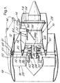
- Figure 1 is a diagrammatic, part cross sectional view of a ducted fan gas turbine engine in accordance with the present invention.
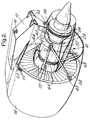
- Figure 2 is a pictorial view of the engine of Figure 1.
- Referring to Figure 1 a ducted fan
gas turbine engine 10, in the particular example, has a three shaft configuration (not shown) ie a high pressure turbine drives a first stage high pressure compressor via a shaft, an intermediate pressure turbine drives an intermediate stage compressor via a further shaft, and a low pressure turbine which receives gas flow from the intermediate stage turbine, drives a fan via a further shaft either directly or through gearing. There is no mechanical drive connection between the three shafts, though bearings space them apart to ensure concentricity therebetween. - The three shaft configuration as described so far, is well known and per se does not form the present invention.
- In Figure 1, a
pylon 12 is fixable, vialugs 14, to an aircraft wing main beam (not shown). Thepylon 12 supports the ducted fangas turbine engine 10 with which the aircraft (not shown) is powered. - The
engine 10 includes afan module 16 having acowl 18, surrounding a stage offan blades 20 which in operation is rotated viagears 22 and ashaft 24, connected to a low pressure turbine stage (not shown) within theturbine casing 26 of acore gas generator 28. - The
cowl 18 is fixed to anannular flange structure 30 made up from flange portions on the outer ends of fan airoutlet guide vanes 32. The inner ends of theguide vanes 32 are joined to acommon ring 34 which defines the outer surface of theair intake 36 for thelow pressure compressor 38 of thecore gas generator 28. -
Struts 40 extend across theair intake 36 to aconical member 42 which defines the inner surface thereof and which in turn surrounds anannular disc 44 housing a bearing 46 by means of which the upstream end portion of thefan shaft 24 is radially supported. - The
fan module 16 is connected to the upstream end of thepylon 12 in the following manner. Apeg 48 fits into a socket between the flanges which provide theflange structure 30, in a direction radially inwardly of theengine 10. The peg 49 transmits theengine 10 thrust loads into thepylon 12 and therefore the aircraft (not shown). -
Links 50 of which only one is shown in Figure 2, extend tangentially of theflange structure 30, on each side of thepeg 48.Links 50 have their ends connected in known manner, to thepylon 12 andlocal flanges 51 betweenflanged structure 30 respectively, so as to counter vertical loads and any tendency of thecowl 18 to rotate about the longitudinal axis of theengine 10. - The
core gas generator 28 comprises thecompressor 38, a high pressure compressor (not shown) combustion equipment (no shown) in acasing 52, and a multistage turbine (not shown) in flow series therewith within thecasing 26.Casing 26 hasdouble flanges 54. Alink structure 56 connects and supports the downstream end of thecore gas generator 28 from thepylon 12 in the same manner aslinks 50 support the fan module ie against vertical and rotational movement. Again, this feature per se, is known. - The connection of the
engine 10 to thepylon 12 as described so far, is not sufficient to obviate bending loads being applied to the coregas generator casing 52 when thefan cowl 18 experiences asymmetric loads. this is because the asymmetric loads cause the fan cowl to pivot about a fulcrum which lies within the area intermediate thelinks 50, the pivoting movement occurring in a clockwise direction as viewed in Figure 1. The resulting loads are transmitted via theguide vanes 32, to the upstream end of the coregas generator casing 52 and causes it to bend. - It has been found that, as a first step towards considerably reducing the bending effect produced by asymmetric loading, the
fan cowl 18 can be stabilised as regards its attitude relative to the remainder of theengine 10, by providing a pair oflinks 58, one end of each of which is connected to thepylon 12, and the ends connected to theflanged structure 30 of theguide vanes 32 atpositions 63 equi-angularly spaced form top dead centre of the fan cowl. This latter feature is shown in Figure 2. - In the present example, in order that the
links 58 may be orientated to positions where the loads they must counter, are applied as near axially thereto as is possible, bearing in mind the spacial constraints imposed by engine structure, ayoke 60 is provided, which is fixed to thepylon 12 so as to be effectively integral therewith and thelinks 58 are connected to respective ends thereby. However,yoke 60 may be obviated andlinks 58 extended to connect with thepylon 12 at its downstream end, again subject to spacial constraints. - The aforementioned first step is of course a bracing arrangement and whilst it reduces the movement of the fan cowl under asymmetric loads, and therefore the bending loads on the core gas generator, it cannot obviate all movement thereof. Therefore, a second step has been devised which converts the remaining fan cowl movement into movement relative to the
core gas generator 28 rather than forcing thecore gas generator 28 to bend. - This is achieved by providing the upstream end of the core
gas generator casing 52 with anannular diaphragm flange 62, which has a thickened rim for the passage of bolts or other suitable fastening means therethrough, and fastening theflange 62 via its thickened rim, to the downstream annular face of thering 34. - The second step further includes dividing the fan shaft into an upstream stub shaft 24a and a downstream main shaft portion 24b and re-joining them by a further
annular diaphragm flange 66 formed, in the present example, on the upstream end of the main shaft portion 64b. - It is preferred that the interfaces of the two joints described hereinbefore lie in a common plane radially of the axis of the
engine 10. - A pair of
thrust links 64 are connected between theyoke 60 and thecasing 52 near its upstream end. This latter connection is shown more clearly in Figure 2. The links transmit the thrust generated by the core gas generator to the aircraft via thepylon 12 and is a well known feature which per se does not form the present invention. - A further pair of
links 68 interconnect thecore gas generator 28 and thecowl 18 to mitigate lateral roll of thecowl 18. The man skilled in the particular art, on reading this specification will appreciate that the combination ofbracing links 58 andflexible diaphragms diaphragms - Whilst the invention has been described hereinbefore with reference to a three shaft engine, it could also be applied to a two shaft engine, wherein the fan is driven via gears, from a shaft which connects a compressor stage and a turbine stage. In this arrangement the flexible diaphragm would be provided on the said connecting shaft.
Claims (9)
- In a combination of a ducted fan gas turbine engine (10) comprising a fan module (16) and a core gas generator, (28) and an aircraft, a method of inter-connecting the fan module (16) comprising a stage of shaft-mounted fan blades (20) surrounded by a cowl (18), and the core gas generator (28) to each other and to the aircraft to be driven thereby comprising the steps of connecting said fan module (16) to aircraft structure via rigid links (50), connecting said core gas generator (28) to said aircraft structure via further rigid links (56), characterised by the step of connecting the fan module (16) to the core gas generator (28) via annular flexible diaphragms (62,66).
- The method of claim 1 characterised by the inclusion of the step of forming the fan shaft (24) from a stub shaft (24a) and a main shaft portion (24b), joined via a flanged annular diaphragm (66).
- The method of claim 1 characterised by the inclusions of the step of forming a radially outwardly turned, flanged annular diaphragm (62) on the upstream end of a casing (52) surrounding the core gas generator (28) and connecting said diaphragm (62) to annular structure (34) on the fan module (16) and which locates the radially inner ends of an air outlet guide vanes (32) on the fan module (16).
- The method of claims 2 and 3 characterised by the inclusion of the step of arranging the planes of the interfaces of the respective diaphragm joints (62,66) in a common plane normal to the engine (10) axis.
- The method as claimed in any of claims 1 to 4 characterised by the inclusion of the step of providing a pylon (12) as said aircraft structure and which is removably fixable to said aircraft and includes connection features for connecting said fan module (16) and said core gas generator (28) thereto.
- The method as claimed in claim 5 characterised by the inclusion of the steps of connecting the fan module (16) to said pylon (12) at its upstream end via rigid links (50) which are arranged such that their lengths are tangential to the periphery of the outer ends of a stage of fan air outlet guide vanes (32) forming part of the fan module (16), in opposing directions and are connected thereto via respective ends, their other ends being connected to the pylon (12) at positions closely adjacent each other and straddling top dead centre of the stage of outlet guide vanes (32), and further connecting the fan module (16) to the pylon (12) at a position intermediate its ends via a further pair of rigid links (58), the other ends of which are connected to said outer ends of said stage of fan air outlet guide vanes (32) at positions equi-angularly spaced from said top dead centre thereof.
- The method as claimed in claim 6 characterised by the inclusion of the step of connecting the core gas generator (28) to said pylon (12) via a pair of rigid links (64) connected between an upstream portion of an outer casing of the core gas generator (28) and said intermediate portion of the pylon (12), and including the further step of connecting the downstream portion of the core gas generator (28) to the downstream end portion of the pylon (12) via links (56) which support the weight of the core gas generator and against rotation thereof.
- The method as claimed in any of claims 5 to 7 characterised by the step of providing the pylon (12) with a yoke (60) which extends partially around the core gas generator (28) in radially spaced relationship in a position intermediate the ends of the pylon (12) and utilising the yoke (60) ends as connection points for said links (58,64).
- The method of claim 8 characterised by the step of forming the yoke (60) separately from the pylon (12) and then removably fixing it thereto so as to be effectively integral therewith for operation.
Applications Claiming Priority (3)
| Application Number | Priority Date | Filing Date | Title |
|---|---|---|---|
| GBGB9602130.8A GB9602130D0 (en) | 1996-02-02 | 1996-02-02 | Improved method of combining ducted fan gas turbine engine modules and aircraft structure |
| GB9602130 | 1996-02-02 | ||
| US08/779,611 US5860275A (en) | 1996-02-02 | 1997-01-07 | Method of combining ducted fan gas turbine engine modules and aircraft structure |
Publications (3)
| Publication Number | Publication Date |
|---|---|
| EP0787895A2 true EP0787895A2 (en) | 1997-08-06 |
| EP0787895A3 EP0787895A3 (en) | 1999-06-02 |
| EP0787895B1 EP0787895B1 (en) | 2002-07-03 |
Family
ID=26308585
Family Applications (1)
| Application Number | Title | Priority Date | Filing Date |
|---|---|---|---|
| EP96309074A Expired - Lifetime EP0787895B1 (en) | 1996-02-02 | 1996-12-12 | Improved method of combining ducted fan gas turbine engine modules and aircraft structure |
Country Status (3)
| Country | Link |
|---|---|
| US (1) | US5860275A (en) |
| EP (1) | EP0787895B1 (en) |
| GB (1) | GB9602130D0 (en) |
Cited By (11)
| Publication number | Priority date | Publication date | Assignee | Title |
|---|---|---|---|---|
| WO1999058852A1 (en) | 1998-05-13 | 1999-11-18 | Otarid Consult Limited | Method of creation of forces for movement of vehicles and device for its embodiment |
| FR2907098A1 (en) * | 2006-10-11 | 2008-04-18 | Aircelle Sa | Nacelle for sheltering e.g. two-flow turbojet, has rear section with external structure rigidly connected to part for supporting turbojet, and attachment unit joining nacelle to pylon that is intended to be connected to fixed structure |
| WO2008043903A3 (en) * | 2006-10-11 | 2008-07-03 | Aircelle Sa | Bypass turbojet engine nacelle |
| EP2233721A1 (en) * | 2009-03-09 | 2010-09-29 | Rolls-Royce plc | Gas turbine engine |
| US7845158B2 (en) | 2006-11-10 | 2010-12-07 | Rolls-Royce Plc | Turbine engine mounting arrangement |
| EP1775428A3 (en) * | 2005-10-14 | 2011-03-16 | Rolls-Royce plc | Fan stator |
| ITCO20100046A1 (en) * | 2010-08-27 | 2012-02-28 | Nuovo Pignone Spa | AXIAL MULTISTAGE EXPANDER DEVICE WITH GEARS, SYSTEM AND METHOD |
| WO2016001581A1 (en) * | 2014-07-03 | 2016-01-07 | Aircelle | Aircraft propulsion assembly |
| FR3040076A1 (en) * | 2015-08-13 | 2017-02-17 | Airbus Operations Sas | AIRCRAFT ENGINE ASSEMBLY COMPRISING A PRIMARY STRUCTURE OF A COUPLING MAT EQUIPPED WITH A BOX EXTENSION COMPRISING TWO PARTS IN GLOBAL ARCEAU SHAPE |
| EP1852595A3 (en) * | 2006-05-06 | 2017-11-01 | Rolls-Royce plc | Aeroengine thrust reverser |
| EP3546708A1 (en) * | 2018-03-29 | 2019-10-02 | Rolls-Royce plc | Turbine engine |
Families Citing this family (36)
| Publication number | Priority date | Publication date | Assignee | Title |
|---|---|---|---|---|
| GB2320525A (en) * | 1996-12-18 | 1998-06-24 | British Aerospace | Mounting of powerplant in aircraft |
| US6401448B1 (en) * | 2000-08-31 | 2002-06-11 | General Electric Company | System for mounting aircraft engines |
| US6786036B2 (en) * | 2001-04-27 | 2004-09-07 | Matthew Scott Kight | Bimodal fan, heat exchanger and bypass air supercharging for piston or rotary driven turbine |
| US6708482B2 (en) | 2001-11-29 | 2004-03-23 | General Electric Company | Aircraft engine with inter-turbine engine frame |
| GB2394991B (en) * | 2002-11-06 | 2006-02-15 | Rolls Royce Plc | Mounting arrangement |
| CA2533425C (en) * | 2003-07-29 | 2012-09-25 | Pratt & Whitney Canada Corp. | Turbofan case and method of making |
| US7370467B2 (en) * | 2003-07-29 | 2008-05-13 | Pratt & Whitney Canada Corp. | Turbofan case and method of making |
| US8033094B2 (en) * | 2004-12-01 | 2011-10-11 | United Technologies Corporation | Cantilevered tip turbine engine |
| SE528948C2 (en) * | 2004-12-23 | 2007-03-20 | Volvo Aero Corp | Annular torque static component for an aircraft engine |
| GB2434836B (en) * | 2006-02-04 | 2008-12-10 | Rolls Royce Plc | Mounting system for use in mounting a gas turbine engine |
| FR2902406B1 (en) * | 2006-06-20 | 2008-07-18 | Airbus France Sas | FITTING FOR SUSPENSION MAT FROM A TURBOMOTEUR TO AN AIRCRAFT WING |
| US7926260B2 (en) * | 2006-07-05 | 2011-04-19 | United Technologies Corporation | Flexible shaft for gas turbine engine |
| GB0613929D0 (en) | 2006-07-13 | 2006-08-23 | Rolls Royce Plc | An engine core stand arrangement and method of removal and transportation of an engine core |
| US8075261B2 (en) * | 2007-09-21 | 2011-12-13 | United Technologies Corporation | Gas turbine engine compressor case mounting arrangement |
| FR2928180B1 (en) * | 2008-02-28 | 2010-04-02 | Airbus France | AIRCRAFT ENGINE ASSEMBLY COMPRISING AN ANNULAR EFFORTS TRANSFER STRUCTURE SURROUNDING THE CENTRAL HOUSING OF A TURBOJET ENGINE. |
| FR2928181B1 (en) * | 2008-02-28 | 2010-04-02 | Airbus France | AIRCRAFT ENGINE ASSEMBLY COMPRISING A TURBOJET ENGINE WITH REINFORCING STRUCTURES CONNECTING THE BLOWER HOUSING TO THE CENTRAL CASING. |
| FR2928136B1 (en) * | 2008-02-28 | 2010-04-02 | Airbus France | AIRCRAFT ENGINE ASSEMBLY COMPRISING ENGINE FASTENERS DEPORTED DOWN TO THE BLOWER HOUSING. |
| FR2933070B1 (en) * | 2008-06-25 | 2010-08-20 | Snecma | PROPULSIVE AIRCRAFT SYSTEM |
| US8147194B2 (en) * | 2008-11-06 | 2012-04-03 | Honeywell International Inc. | Turbine engine components |
| US8567202B2 (en) * | 2009-05-15 | 2013-10-29 | Pratt & Whitney Canada Corp. | Support links with lockable adjustment feature |
| US8979491B2 (en) | 2009-05-15 | 2015-03-17 | Pratt & Whitney Canada Corp. | Turbofan mounting arrangement |
| US8313293B2 (en) * | 2009-05-15 | 2012-11-20 | Pratt & Whitney Canada Corp. | Turbofan mounting system |
| US8720059B2 (en) * | 2010-04-29 | 2014-05-13 | Spirit Aerosystems, Inc. | Apparatus and method for aircraft engine core exchange |
| GB201017303D0 (en) * | 2010-10-14 | 2010-11-24 | Rolls Royce Plc | Support structure |
| US8777793B2 (en) | 2011-04-27 | 2014-07-15 | United Technologies Corporation | Fan drive planetary gear system integrated carrier and torque frame |
| US9228451B2 (en) | 2011-05-03 | 2016-01-05 | Pratt & Whitney Canada Corp. | Gas turbine engine module adapter to a carrier |
| US10400629B2 (en) | 2012-01-31 | 2019-09-03 | United Technologies Corporation | Gas turbine engine shaft bearing configuration |
| US8863491B2 (en) | 2012-01-31 | 2014-10-21 | United Technologies Corporation | Gas turbine engine shaft bearing configuration |
| US9038366B2 (en) | 2012-01-31 | 2015-05-26 | United Technologies Corporation | LPC flowpath shape with gas turbine engine shaft bearing configuration |
| US20130232768A1 (en) | 2012-03-12 | 2013-09-12 | United Technologies Corporation | Turbine engine case mount and dismount |
| US9212607B2 (en) | 2012-07-18 | 2015-12-15 | Spirit Aerosystems, Inc. | Intermediate structure for independently de-mountable propulsion components |
| EP3690211A1 (en) | 2012-10-08 | 2020-08-05 | United Technologies Corporation | Geared turbine engine with relatively lightweight propulsor module |
| GB201418396D0 (en) * | 2014-10-17 | 2014-12-03 | Rolls Royce Plc | Gas turbine engine support structures |
| GB201521871D0 (en) | 2015-12-11 | 2016-01-27 | Rolls Royce Plc | Nacelle |
| US10814993B2 (en) | 2017-08-21 | 2020-10-27 | Raytheon Technologies Corporation | Inlet cowl deflection limiting strut |
| US11549373B2 (en) | 2020-12-16 | 2023-01-10 | Raytheon Technologies Corporation | Reduced deflection turbine rotor |
Family Cites Families (12)
| Publication number | Priority date | Publication date | Assignee | Title |
|---|---|---|---|---|
| GB197803A (en) * | 1922-03-31 | 1923-05-24 | Hugh Walter Mckenna | Improvements in or relating to devices for landing goods or articles from aircraft |
| US2680346A (en) * | 1951-09-10 | 1954-06-08 | Northrop Aircraft Inc | Jet engine inlet duct coupling |
| GB2043833B (en) * | 1979-03-17 | 1982-11-10 | Rolls Royce | Rotor assembly |
| US4371133A (en) * | 1979-05-01 | 1983-02-01 | Edgley Aircraft Limited | Ducted propeller aircraft |
| US4361296A (en) * | 1980-03-10 | 1982-11-30 | The Boeing Company | Uniflange coupling assembly |
| GB2079402B (en) * | 1980-06-27 | 1984-02-22 | Rolls Royce | System for supporting a rotor in conditions of dynamic imbalance |
| US4603821A (en) * | 1983-12-30 | 1986-08-05 | The Boeing Company | System for mounting a jet engine |
| DE3717632A1 (en) * | 1987-05-26 | 1988-12-15 | Porsche Ag | DRIVE DEVICE FOR A VEHICLE WITH A PROPELLER |
| US4811919A (en) * | 1987-08-06 | 1989-03-14 | Lord Corporation | Volume compensated fluid mount |
| GB2275308B (en) * | 1993-02-20 | 1997-02-26 | Rolls Royce Plc | A mounting for coupling a turbofan gas turbine engine to an aircraft structure |
| US5452575A (en) * | 1993-09-07 | 1995-09-26 | General Electric Company | Aircraft gas turbine engine thrust mount |
| US5524847A (en) * | 1993-09-07 | 1996-06-11 | United Technologies Corporation | Nacelle and mounting arrangement for an aircraft engine |
-
1996
- 1996-02-02 GB GBGB9602130.8A patent/GB9602130D0/en active Pending
- 1996-12-12 EP EP96309074A patent/EP0787895B1/en not_active Expired - Lifetime
-
1997
- 1997-01-07 US US08/779,611 patent/US5860275A/en not_active Expired - Fee Related
Non-Patent Citations (1)
| Title |
|---|
| None |
Cited By (18)
| Publication number | Priority date | Publication date | Assignee | Title |
|---|---|---|---|---|
| WO1999058852A1 (en) | 1998-05-13 | 1999-11-18 | Otarid Consult Limited | Method of creation of forces for movement of vehicles and device for its embodiment |
| EP1775428A3 (en) * | 2005-10-14 | 2011-03-16 | Rolls-Royce plc | Fan stator |
| EP1852595A3 (en) * | 2006-05-06 | 2017-11-01 | Rolls-Royce plc | Aeroengine thrust reverser |
| CN101522524B (en) * | 2006-10-11 | 2012-08-29 | 埃尔塞乐公司 | Bypass turbojet engine nacelle |
| FR2907098A1 (en) * | 2006-10-11 | 2008-04-18 | Aircelle Sa | Nacelle for sheltering e.g. two-flow turbojet, has rear section with external structure rigidly connected to part for supporting turbojet, and attachment unit joining nacelle to pylon that is intended to be connected to fixed structure |
| WO2008043903A3 (en) * | 2006-10-11 | 2008-07-03 | Aircelle Sa | Bypass turbojet engine nacelle |
| US8523516B2 (en) | 2006-10-11 | 2013-09-03 | Aircelle | Bypass turbojet engine nacelle |
| US7845158B2 (en) | 2006-11-10 | 2010-12-07 | Rolls-Royce Plc | Turbine engine mounting arrangement |
| EP2233721A1 (en) * | 2009-03-09 | 2010-09-29 | Rolls-Royce plc | Gas turbine engine |
| EP2423487A1 (en) * | 2010-08-27 | 2012-02-29 | Nuovo Pignone S.p.A. | Geared axial multistage expander system and assembly method |
| ITCO20100046A1 (en) * | 2010-08-27 | 2012-02-28 | Nuovo Pignone Spa | AXIAL MULTISTAGE EXPANDER DEVICE WITH GEARS, SYSTEM AND METHOD |
| US9995143B2 (en) | 2010-08-27 | 2018-06-12 | Nuovo Pignone S.P.A. | Geared axial multistage expander device, system and method |
| WO2016001581A1 (en) * | 2014-07-03 | 2016-01-07 | Aircelle | Aircraft propulsion assembly |
| FR3023260A1 (en) * | 2014-07-03 | 2016-01-08 | Aircelle Sa | PROPELLANT AIRCRAFT ASSEMBLY |
| US9963999B2 (en) | 2014-07-03 | 2018-05-08 | Safran Nacelles | Aircraft propulsion assembly |
| FR3040076A1 (en) * | 2015-08-13 | 2017-02-17 | Airbus Operations Sas | AIRCRAFT ENGINE ASSEMBLY COMPRISING A PRIMARY STRUCTURE OF A COUPLING MAT EQUIPPED WITH A BOX EXTENSION COMPRISING TWO PARTS IN GLOBAL ARCEAU SHAPE |
| US10017267B2 (en) | 2015-08-13 | 2018-07-10 | Airbus Operations Sas | Engine assembly for an aircraft comprising a primary structure of a mounting pylon equipped with a box extension comprising two parts in the overall shape of an arch |
| EP3546708A1 (en) * | 2018-03-29 | 2019-10-02 | Rolls-Royce plc | Turbine engine |
Also Published As
| Publication number | Publication date |
|---|---|
| GB9602130D0 (en) | 1996-04-03 |
| EP0787895B1 (en) | 2002-07-03 |
| US5860275A (en) | 1999-01-19 |
| EP0787895A3 (en) | 1999-06-02 |
Similar Documents
| Publication | Publication Date | Title |
|---|---|---|
| EP0787895B1 (en) | Improved method of combining ducted fan gas turbine engine modules and aircraft structure | |
| US6708482B2 (en) | Aircraft engine with inter-turbine engine frame | |
| US4785625A (en) | Ducted fan gas turbine power plant mounting | |
| US6976655B2 (en) | Mounting arrangement | |
| US7677047B2 (en) | Inverted stiffened shell panel torque transmission for loaded struts and mid-turbine frames | |
| US6855089B2 (en) | Reduced twist carrier | |
| US7739866B2 (en) | Turbofan case and method of making | |
| US4375906A (en) | System for supporting a rotor in a conditions of accidental dynamic imbalance | |
| US9003812B2 (en) | Supporting structure for a gas turbine engine | |
| US7266941B2 (en) | Turbofan case and method of making | |
| US8444085B2 (en) | Support structure | |
| GB2275308A (en) | A mounting for coupling a turbofan gas turbine engine to an aircraft structure. | |
| CN112923028A (en) | Reliable gearbox for gas turbine engine | |
| US5419112A (en) | Gas turbine powerplant | |
| CN112923029A (en) | High power epicyclic gearbox and operation thereof | |
| US4766723A (en) | Turbofan gas turbine engine and mountings therefore | |
| US5941683A (en) | Gas turbine engine support structure | |
| JPH10507425A (en) | Nacelles for aircraft engines and their mounting arrangements | |
| CN112918683A (en) | Aircraft engine | |
| CN112923031A (en) | Gas turbine engine arrangement | |
| US5428952A (en) | Geodesic engine mount structure | |
| US20220003354A1 (en) | Gas turbine engine casing arrangement | |
| EP4194339B1 (en) | Support structure for attaching a gas turbine engine to an aircraft pylon | |
| CN116635618A (en) | Aircraft turbine engine assembly comprising a bracket for a fitting | |
| CN116280221A (en) | Support structure for attaching a gas turbine engine to an aircraft pylon |
Legal Events
| Date | Code | Title | Description |
|---|---|---|---|
| PUAI | Public reference made under article 153(3) epc to a published international application that has entered the european phase |
Free format text: ORIGINAL CODE: 0009012 |
|
| 17P | Request for examination filed |
Effective date: 19961223 |
|
| AK | Designated contracting states |
Kind code of ref document: A2 Designated state(s): DE FR GB |
|
| PUAL | Search report despatched |
Free format text: ORIGINAL CODE: 0009013 |
|
| AK | Designated contracting states |
Kind code of ref document: A3 Designated state(s): DE FR GB |
|
| 17Q | First examination report despatched |
Effective date: 20010323 |
|
| GRAG | Despatch of communication of intention to grant |
Free format text: ORIGINAL CODE: EPIDOS AGRA |
|
| GRAG | Despatch of communication of intention to grant |
Free format text: ORIGINAL CODE: EPIDOS AGRA |
|
| GRAH | Despatch of communication of intention to grant a patent |
Free format text: ORIGINAL CODE: EPIDOS IGRA |
|
| GRAH | Despatch of communication of intention to grant a patent |
Free format text: ORIGINAL CODE: EPIDOS IGRA |
|
| GRAA | (expected) grant |
Free format text: ORIGINAL CODE: 0009210 |
|
| AK | Designated contracting states |
Kind code of ref document: B1 Designated state(s): DE FR GB |
|
| REF | Corresponds to: |
Ref document number: 69622145 Country of ref document: DE Date of ref document: 20020808 |
|
| ET | Fr: translation filed | ||
| PLBE | No opposition filed within time limit |
Free format text: ORIGINAL CODE: 0009261 |
|
| STAA | Information on the status of an ep patent application or granted ep patent |
Free format text: STATUS: NO OPPOSITION FILED WITHIN TIME LIMIT |
|
| 26N | No opposition filed |
Effective date: 20030404 |
|
| PGFP | Annual fee paid to national office [announced via postgrant information from national office to epo] |
Ref country code: GB Payment date: 20091218 Year of fee payment: 14 Ref country code: FR Payment date: 20100108 Year of fee payment: 14 |
|
| PGFP | Annual fee paid to national office [announced via postgrant information from national office to epo] |
Ref country code: DE Payment date: 20091222 Year of fee payment: 14 |
|
| GBPC | Gb: european patent ceased through non-payment of renewal fee |
Effective date: 20101212 |
|
| REG | Reference to a national code |
Ref country code: FR Ref legal event code: ST Effective date: 20110831 |
|
| PG25 | Lapsed in a contracting state [announced via postgrant information from national office to epo] |
Ref country code: FR Free format text: LAPSE BECAUSE OF NON-PAYMENT OF DUE FEES Effective date: 20110103 |
|
| REG | Reference to a national code |
Ref country code: DE Ref legal event code: R119 Ref document number: 69622145 Country of ref document: DE Effective date: 20110701 |
|
| PG25 | Lapsed in a contracting state [announced via postgrant information from national office to epo] |
Ref country code: GB Free format text: LAPSE BECAUSE OF NON-PAYMENT OF DUE FEES Effective date: 20101212 Ref country code: DE Free format text: LAPSE BECAUSE OF NON-PAYMENT OF DUE FEES Effective date: 20110701 |