EP0788397B1 - A vessel for filtering liquids, particularly drinking water - Google Patents
A vessel for filtering liquids, particularly drinking water Download PDFInfo
- Publication number
- EP0788397B1 EP0788397B1 EP95937020A EP95937020A EP0788397B1 EP 0788397 B1 EP0788397 B1 EP 0788397B1 EP 95937020 A EP95937020 A EP 95937020A EP 95937020 A EP95937020 A EP 95937020A EP 0788397 B1 EP0788397 B1 EP 0788397B1
- Authority
- EP
- European Patent Office
- Prior art keywords
- lid
- container
- vessel
- counting
- disc
- Prior art date
- Legal status (The legal status is an assumption and is not a legal conclusion. Google has not performed a legal analysis and makes no representation as to the accuracy of the status listed.)
- Expired - Lifetime
Links
- 238000001914 filtration Methods 0.000 title claims abstract description 12
- 239000007788 liquid Substances 0.000 title claims abstract description 8
- 239000003651 drinking water Substances 0.000 title claims description 3
- 235000020188 drinking water Nutrition 0.000 title claims description 3
- 230000015572 biosynthetic process Effects 0.000 description 2
- XLYOFNOQVPJJNP-UHFFFAOYSA-N water Substances O XLYOFNOQVPJJNP-UHFFFAOYSA-N 0.000 description 2
- 230000008878 coupling Effects 0.000 description 1
- 238000010168 coupling process Methods 0.000 description 1
- 238000005859 coupling reaction Methods 0.000 description 1
- 230000000694 effects Effects 0.000 description 1
- 238000003780 insertion Methods 0.000 description 1
- 230000037431 insertion Effects 0.000 description 1
- 238000012544 monitoring process Methods 0.000 description 1
- 230000010355 oscillation Effects 0.000 description 1
- 230000000007 visual effect Effects 0.000 description 1
Images


Classifications
-
- C—CHEMISTRY; METALLURGY
- C02—TREATMENT OF WATER, WASTE WATER, SEWAGE, OR SLUDGE
- C02F—TREATMENT OF WATER, WASTE WATER, SEWAGE, OR SLUDGE
- C02F1/00—Treatment of water, waste water, or sewage
- C02F1/001—Processes for the treatment of water whereby the filtration technique is of importance
- C02F1/003—Processes for the treatment of water whereby the filtration technique is of importance using household-type filters for producing potable water, e.g. pitchers, bottles, faucet mounted devices
-
- B—PERFORMING OPERATIONS; TRANSPORTING
- B01—PHYSICAL OR CHEMICAL PROCESSES OR APPARATUS IN GENERAL
- B01D—SEPARATION
- B01D35/00—Filtering devices having features not specifically covered by groups B01D24/00 - B01D33/00, or for applications not specifically covered by groups B01D24/00 - B01D33/00; Auxiliary devices for filtration; Filter housing constructions
- B01D35/14—Safety devices specially adapted for filtration; Devices for indicating clogging
- B01D35/143—Filter condition indicators
-
- B—PERFORMING OPERATIONS; TRANSPORTING
- B01—PHYSICAL OR CHEMICAL PROCESSES OR APPARATUS IN GENERAL
- B01D—SEPARATION
- B01D37/00—Processes of filtration
- B01D37/04—Controlling the filtration
-
- C—CHEMISTRY; METALLURGY
- C02—TREATMENT OF WATER, WASTE WATER, SEWAGE, OR SLUDGE
- C02F—TREATMENT OF WATER, WASTE WATER, SEWAGE, OR SLUDGE
- C02F2209/00—Controlling or monitoring parameters in water treatment
- C02F2209/44—Time
- C02F2209/445—Filter life
-
- C—CHEMISTRY; METALLURGY
- C02—TREATMENT OF WATER, WASTE WATER, SEWAGE, OR SLUDGE
- C02F—TREATMENT OF WATER, WASTE WATER, SEWAGE, OR SLUDGE
- C02F2307/00—Location of water treatment or water treatment device
- C02F2307/04—Location of water treatment or water treatment device as part of a pitcher or jug
Definitions
- the subject of the invention is a vessel for filtering liquids, particularly drinking water, according to the preamble of claim.
- a vessel is of the type which has a replaceable filter cartridge and in which, to ensure efficient filtering, the filetr cartridge has to be removed and replaced after a certain number of cycles and/or after a predetermined period of time.
- a vessel for filtering liquids having the features outlined above is known from US 5 190 643.
- the object of the invention is to provide a filtering vessel, the structure and operation of which are such as to facilitate the user's task of monitoring the efficiency of the filter cartridge in order to replace it once the useful filtering cycles provided for have been carried out.
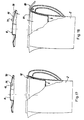
- a vessel according to the present invention is generally indicated 1; it comprises a jug 2 with a handle 3 and a spout 4 for pouring out the filtered water, a funnel-shaped container 5 housed in the jug 2 and supported with form coupling in a mouth portion 7 thereof and a lid 8 positioned removably for closing the container 5.
- the container 5 defines, in known manner, a receptacle 9, in the base of which there is a housing 10 for a filter cartridge 11 replaceable, for example, after a predetermined number of filtering cycles.
- a filter cartridge 11 replaceable, for example, after a predetermined number of filtering cycles.
- a plate-like catch projection 12 projects radially inwardly from the wall of the receptacle 9 of the container 5 on the side facing the spout 4.
- the lid 8 has a device, generally indicated 15, for counting the number of filtering cycles carried out by the cartridge 11.
- the device 15 comprises a display disc 16 which is rotatable about a peg 17 integral with the lid 8 and is urged resiliently against the facing wall 21 of the lid 8 by means of a helical spring 18 which abuts the head of a pin 19 driven into the peg 17.
- a scale 22 graduated in numbered sectors is printed on the face of the disc 16 facing the wall 21; for each sector of the scale 22 the outer.edge of the disc 16 has a respective trapezoidal tooth 23 with a face 24 which is substantially vertical or is disposed in a plane containing the axis of rotation of the disc, and with two sides 25a, 25b tapered like inclined planes.
- the teeth are spaced apart by respective recesses with flat bases 26.
- One of the recesses 26 between two adjacent teeth of the disc 16 is at least partially blocked by a bridge 27 provided for stopping the disc 16 upon completion of a predetermined rotation as will be explained further below.
- the bridge 27 is shown in a fictitious angular position, purely by way of example and for clarity of the drawing; it would actually be diametrally opposite the sector bearing the word "STOP" and hence in a position not visible in the drawing.
- the opposite face of the disc 16 has a grip 28 (which serves for the manual rotation of the disc 16) and an opposed indicator arrow 29.
- the wall 21 of the lid 8 has a window 30 extending through the lid to enable the scale 22 to be seen from outside the container 5, an indicator arrow 31 which is intended to correspond to the arrow 29 for the initial positioning of the disc 16 after the filter cartridge 11 has been replaced, a unidirectional stop tooth 32 for the disc 16 to prevent it from rotating backwards and two appendages, indicated 33 and 34, respectively.
- the appendage 33 serves as a shoulder for a spring 35 which urges a pawl 36 resiliently into abutment against the appendage 34.
- the pawl 36 is supported for pivoting on the peg 17 and bears a unidirectional stop tooth 37 for advancing the disc as well as a cam profile 38 with a ramp or inclined plane which can cooperate with the catch projection 12 of the receptacle portion 9 to bring about a complete oscillation of the pawl 36 as a result of each opening and subsequent closure of the lid 8.
- the pawl 36 with the unidirectional stop tooth 32 and the set of teeth 23 formed on the edge of the disc 16 constitute an escapement ratchet mechanism for the stepped rotation of the disc 16 upon each opening and subsequent closure of the lid 8.
- the disc 16 can pass over both the tooth 32 and the tooth 37 owing to the resilience of its mounting on the peg 17.
- the vessel just described operates as follows.
- the water to be filtered is first introduced into the container 5 after the lid 8 has been removed.
- the pawl is pivoted in the sense indicated by the arrow A under the action of the spring 35 and the stop tooth 37 formed thereon is made to pass over the tooth adjacent that previously engaged by sliding on the inclined planes of the sides 25a, 25b thereof.
- the pawl is thus prepared for entraining the disc 16 upon subsequent closure of the container by means of the lid 8.
- the unidirectional stop tooth 37 of the pawl 36 is brought to the bridge-like cross-piece 27 between two adjacent teeth 23, whereas the unidirectional stop tooth 32 correctly prevents the disc from rotating backwards, any further rotation of the disc 16 is prevented, possibly with the display through the window 30 of an indication advising that the cartridge 11 should be replaced.
- the vessel of Figures 8 to 10 differs from the previous one in that, instead of the display disc, it has a drum-like counting device 40 supported for rotation between two shoulders 41a, 41b and rotated in steps about its own axis by an escapement ratchet mechanism 42 of which the pawl, indicated 43, is supported on the lid 8 on a pin 48 and is acted on resiliently by a spring 49.
- the pawl 43 comprises a resilient arm 44 carrying two hooks 45a, 45b, each in engagement with a respective set of teeth 46a, 46b and is pivoted about the pin 48 by interference with the catch projection 12 upon each opening and subsequent closure of the lid onto the container 5.
- the pawl 36 is slidable longitudinally on the lid 8 rather than being pivotable.
- the cam profile 38 is a profile with an inclined plane cooperating with a corresponding inclined plane 50 on the catch projection 12.
- the pawl 36 bears a resilient arm 51 on the free end of which a hook 52 is formed; on the opposite side, the pawl has a catch formation 53 for limiting the rotation of the display disc 16 in one sense.
- the display disc 16 has a plurality of teeth 54 with sawtooth profiles on its upper face facing the surface 21 of the lid 8.
- FIG. 14 to 16 differs from the previous embodiment essentially in that, in this embodiment, the catch-like formation 53 is replaced by a separate hook 60 mounted for limited pivoting on the lid 8 with the ability for an arm 61 of the hook 60 to catch against a lateral wall 62 of the lid 8.
- the count which can be read in the display 71 visible through the window 30 is operated by the catch projection 12 which operates a push-button 70 mounted on the electronic counting device 15 fixed to the lid 8.
- the electronic counting device 15 is operated by a lever 80 a front portion 81 of which acts on the push-button 70 which, upon the closure of the lid 8 also rotates the numbering on the display 71 visible on the upper wall of the electronic device 15.
- the display 71 ( Figure 19) is operated by a magnetic mass 90 acted on by a magnet 91 mounted on the receptacle 9.
- an attraction or repulsion effect of the magnet 91 on the magnetic mass 90 may be provided for without distinction.
Abstract
Description
- The subject of the invention is a vessel for filtering liquids, particularly drinking water, according to the preamble of claim.
- A vessel is of the type which has a replaceable filter cartridge and in which, to ensure efficient filtering, the filetr cartridge has to be removed and replaced after a certain number of cycles and/or after a predetermined period of time.
A vessel for filtering liquids having the features outlined above is known from US 5 190 643. - The object of the invention is to provide a filtering vessel, the structure and operation of which are such as to facilitate the user's task of monitoring the efficiency of the filter cartridge in order to replace it once the useful filtering cycles provided for have been carried out.
- This object is achieved by a vessel formed in accordance with the claims below.
- The characteristics and advantages of the invention will become clearer from the detailed description of some preferred but not exclusive embodiments thereof illustrated in the appended drawings, in which:
- Figure 1 is a front elevational view of a vessel according to the invention shown in partial section,
- Figure 2 is a partially-sectioned plan view of a detail of the vessel from above,
- Figure 3 is a partially-sectioned perspective view of a further detail of the same vessel from above,
- Figure 4 is an exploded perspective view of the detail of Figure 3 from below,
- Figure 5 is a longitudinal section of a first variant of the vessel of the previous drawings, shown only partially,
- Figure 6 is a section taken on the line VI-VI of Figure 5,
- Figure 7 is a partially-sectioned plan view of the vessel of Figures 5 and 6 from above,
- Figure 8 is a longitudinal section of a second variant of the vessel of the previous drawings, shown only partially,
- Figure 9 is a section taken on the line IX-IX of Figure 8,
- Figure 10 is a partially-sectioned plan view of the vessel of Figures 8 and 9 from above,
- Figure 11 is a longitudinal section of a third variant of the vessel of the previous drawings, shown only partially,
- Figure 12 is a section taken on the line XII-XII of Figure 11,
- Figure 13 is a partially-sectioned plan view of the vessel of Figures 11 and 12 from above,
- Figure 14 is a longitudinal section of a fourth variant of the vessel of the previous drawings, shown only partially,
- Figure 15 is a section taken on the line XV-XV of Figure 14,
- Figure 16 is a partially-sectioned plan view of the vessel of Figures 14 and 15 from above,
- Figures 17, 18 and 19 are partially-sectioned side elevational views of three further variants of the vessel of the invention.
-
- In Figures 1 to 3, a vessel according to the present invention is generally indicated 1; it comprises a
jug 2 with ahandle 3 and a spout 4 for pouring out the filtered water, a funnel-shaped container 5 housed in thejug 2 and supported with form coupling in a mouth portion 7 thereof and alid 8 positioned removably for closing thecontainer 5. - The
container 5 defines, in known manner, a receptacle 9, in the base of which there is a housing 10 for afilter cartridge 11 replaceable, for example, after a predetermined number of filtering cycles. By way of indication, it may be assumed that thecartridge 11 is arranged to perform thirty filtering cycles and has to be replaced upon completion of the thirtieth cycle. - A plate-
like catch projection 12 projects radially inwardly from the wall of the receptacle 9 of thecontainer 5 on the side facing the spout 4. - According to the invention, the
lid 8 has a device, generally indicated 15, for counting the number of filtering cycles carried out by thecartridge 11. Thedevice 15 comprises adisplay disc 16 which is rotatable about apeg 17 integral with thelid 8 and is urged resiliently against the facingwall 21 of thelid 8 by means of ahelical spring 18 which abuts the head of a pin 19 driven into thepeg 17. - A
scale 22 graduated in numbered sectors is printed on the face of thedisc 16 facing thewall 21; for each sector of thescale 22 the outer.edge of thedisc 16 has a respectivetrapezoidal tooth 23 with a face 24 which is substantially vertical or is disposed in a plane containing the axis of rotation of the disc, and with twosides 25a, 25b tapered like inclined planes. The teeth are spaced apart by respective recesses withflat bases 26. - One of the
recesses 26 between two adjacent teeth of thedisc 16 is at least partially blocked by abridge 27 provided for stopping thedisc 16 upon completion of a predetermined rotation as will be explained further below. In the embodiment illustrated, thebridge 27 is shown in a fictitious angular position, purely by way of example and for clarity of the drawing; it would actually be diametrally opposite the sector bearing the word "STOP" and hence in a position not visible in the drawing. - The opposite face of the
disc 16 has a grip 28 (which serves for the manual rotation of the disc 16) and anopposed indicator arrow 29. - In addition to the
peg 17, thewall 21 of thelid 8 has awindow 30 extending through the lid to enable thescale 22 to be seen from outside thecontainer 5, anindicator arrow 31 which is intended to correspond to thearrow 29 for the initial positioning of thedisc 16 after thefilter cartridge 11 has been replaced, aunidirectional stop tooth 32 for thedisc 16 to prevent it from rotating backwards and two appendages, indicated 33 and 34, respectively. Theappendage 33 serves as a shoulder for aspring 35 which urges apawl 36 resiliently into abutment against theappendage 34. Thepawl 36 is supported for pivoting on thepeg 17 and bears aunidirectional stop tooth 37 for advancing the disc as well as acam profile 38 with a ramp or inclined plane which can cooperate with thecatch projection 12 of the receptacle portion 9 to bring about a complete oscillation of thepawl 36 as a result of each opening and subsequent closure of thelid 8. - The
pawl 36 with theunidirectional stop tooth 32 and the set ofteeth 23 formed on the edge of thedisc 16 constitute an escapement ratchet mechanism for the stepped rotation of thedisc 16 upon each opening and subsequent closure of thelid 8. - It can be seen that, as it rotates about its own axis, the
disc 16 can pass over both thetooth 32 and thetooth 37 owing to the resilience of its mounting on thepeg 17. - The vessel just described operates as follows. The water to be filtered is first introduced into the
container 5 after thelid 8 has been removed. When the lid is removed, the pawl is pivoted in the sense indicated by the arrow A under the action of thespring 35 and thestop tooth 37 formed thereon is made to pass over the tooth adjacent that previously engaged by sliding on the inclined planes of thesides 25a, 25b thereof. - The pawl is thus prepared for entraining the
disc 16 upon subsequent closure of the container by means of thelid 8. - When this occurs, the engagement between the
catch projection 12 on the container and thecam profile 38 on the pawl causes the latter to pivot about its own axis in the sense indicated by the arrow B, entraining the display disc by one step. - When, however, upon completion of the thirtieth opening and closure cycle of the
lid 8, theunidirectional stop tooth 37 of thepawl 36 is brought to the bridge-like cross-piece 27 between twoadjacent teeth 23, whereas theunidirectional stop tooth 32 correctly prevents the disc from rotating backwards, any further rotation of thedisc 16 is prevented, possibly with the display through thewindow 30 of an indication advising that thecartridge 11 should be replaced. - In the variants of the vessel of the invention, similar or functionally equivalent details are indicated by the same reference numerals as in the embodiment just described. The vessel of Figures 5 to 7 differs from the embodiment described in that the
spring 35 is formed integrally with thepawl 36. The remaining details and the operation of the counting device are equivalent to those of thevessel 1. - The vessel of Figures 8 to 10 differs from the previous one in that, instead of the display disc, it has a drum-
like counting device 40 supported for rotation between twoshoulders 41a, 41b and rotated in steps about its own axis by anescapement ratchet mechanism 42 of which the pawl, indicated 43, is supported on thelid 8 on apin 48 and is acted on resiliently by aspring 49. The pawl 43 comprises a resilient arm 44 carrying twohooks 45a, 45b, each in engagement with a respective set ofteeth 46a, 46b and is pivoted about thepin 48 by interference with thecatch projection 12 upon each opening and subsequent closure of the lid onto thecontainer 5. - In the vessel of Figures 11 to 13, the
pawl 36 is slidable longitudinally on thelid 8 rather than being pivotable. Thecam profile 38 is a profile with an inclined plane cooperating with a correspondinginclined plane 50 on thecatch projection 12. On one side, thepawl 36 bears aresilient arm 51 on the free end of which ahook 52 is formed; on the opposite side, the pawl has acatch formation 53 for limiting the rotation of thedisplay disc 16 in one sense. - The
display disc 16 has a plurality of teeth 54 with sawtooth profiles on its upper face facing thesurface 21 of thelid 8. - The embodiment of Figures 14 to 16 differs from the previous embodiment essentially in that, in this embodiment, the catch-
like formation 53 is replaced by aseparate hook 60 mounted for limited pivoting on thelid 8 with the ability for anarm 61 of thehook 60 to catch against alateral wall 62 of thelid 8. - Further embodiments of the vessel of the invention are described with reference to Figures 17 to 19. All of these embodiments have in common the fact that the
counting device 15 associated with thelid 8 of the vessel has electronic counting means which enable the number of openings and closures of thevessel 1 carried out to be memorized in order to warn the user automatically by a signal, for example, a sound or visual signal, that thefilter cartridge 11 should be replaced. - Provision is also made for the insertion of a suitable timer in the device for warning that the
cartridge 11 has expired, for example, owing to age, and should therefore be replaced regardless of the number of openings and closures of thelid 8. - In the embodiment shown in Figure 17, the count which can be read in the
display 71 visible through thewindow 30 is operated by thecatch projection 12 which operates a push-button 70 mounted on theelectronic counting device 15 fixed to thelid 8. - In the embodiment shown in Figure 18, the
electronic counting device 15 is operated by a lever 80 afront portion 81 of which acts on the push-button 70 which, upon the closure of thelid 8 also rotates the numbering on thedisplay 71 visible on the upper wall of theelectronic device 15. - In a further variant of the device of the invention, the display 71 (Figure 19) is operated by a
magnetic mass 90 acted on by amagnet 91 mounted on the receptacle 9. - Naturally, an attraction or repulsion effect of the
magnet 91 on themagnetic mass 90 may be provided for without distinction.
Claims (6)
- A vessel for filtering liquids, particularly drinking water, comprising a container (5) for the liquid to be filtered, a lid (8) removably fitted on the container for access thereto, and a counting device (15) for detecting and counting the occasions on which access is gained to the container (5) for pouring therein liquid to be filtered, characterized in that said counting device (15) is associated to said lid (8) and container (5) for detecting and. counting the occasions on which access is gained to the container by means of removal of said lid.
- A vessel according to Claim 1, in which the counting device (15) comprises a ratchet mechanism (16, 36) mounted on the lid (8) or on the container (5) and operatively associated with a display (16), the ratchet mechanism comprising an operating catch projection (12) cooperating with a profile (38) on the container (5) or on the lid (8), respectively, in order to advance the display (16) in steps as a result of each opening and closure of the lid (8).
- A vessel according to Claim 2, in which the ratchet mechanism is of the escapement type.
- A vessel according to Claim 3, in which the ratchet mechanism and the display (16, 36) are mounted on the lid (8) and the operating catch projection (12) is formed on the container in a position such as to interfere with the profile (38) during the opening and closure of the lid (8).
- A vessel according to Claim 3, in which the ratchet mechanism comprises a toothed disc-shaped element (16) and a pawl (36) acting on the teeth (23) of the disc-shaped element (16), both being engaged on the lid (8) coaxially with one another.
- A vessel according to Claim 1, in which the counting device (15) is electronic or electro-mechanical and comprises a pulse generator (12, 70; 81, 70; 90, 91) which can generate a pulse for each opening and/or closure of the lid (8), a counter (15) for counting the pulses generated by the generator and a display (71) for displaying the pulses counted.
Priority Applications (1)
| Application Number | Priority Date | Filing Date | Title |
|---|---|---|---|
| SI9530474T SI0788397T1 (en) | 1994-10-28 | 1995-10-27 | A vessel for filtering liquids, particularly drinking water |
Applications Claiming Priority (5)
| Application Number | Priority Date | Filing Date | Title |
|---|---|---|---|
| IT94VI000156A IT1267870B1 (en) | 1994-10-28 | 1994-10-28 | Device for counting the opening and closing operations of a container |
| ITVI940156 | 1994-10-28 | ||
| ITVI950024 | 1995-02-10 | ||
| IT95VI000024A IT1280685B1 (en) | 1995-02-10 | 1995-02-10 | Counting device with electronic means of counting the operations of opening and closing of a vessel |
| PCT/EP1995/004231 WO1996013318A1 (en) | 1994-10-28 | 1995-10-27 | A vessel for filtering liquids, particularly drinking water |
Publications (2)
| Publication Number | Publication Date |
|---|---|
| EP0788397A1 EP0788397A1 (en) | 1997-08-13 |
| EP0788397B1 true EP0788397B1 (en) | 2000-12-27 |
Family
ID=26332592
Family Applications (1)
| Application Number | Title | Priority Date | Filing Date |
|---|---|---|---|
| EP95937020A Expired - Lifetime EP0788397B1 (en) | 1994-10-28 | 1995-10-27 | A vessel for filtering liquids, particularly drinking water |
Country Status (18)
| Country | Link |
|---|---|
| US (1) | US5900138A (en) |
| EP (1) | EP0788397B1 (en) |
| JP (1) | JP3856469B2 (en) |
| KR (1) | KR100390613B1 (en) |
| CN (1) | CN1069843C (en) |
| AT (1) | ATE198282T1 (en) |
| AU (1) | AU701401B2 (en) |
| BR (1) | BR9509445A (en) |
| CA (1) | CA2203894C (en) |
| DE (1) | DE69519744T2 (en) |
| DK (1) | DK0788397T3 (en) |
| ES (1) | ES2155142T3 (en) |
| GR (1) | GR3035625T3 (en) |
| MX (1) | MX9703005A (en) |
| PL (1) | PL180198B1 (en) |
| PT (1) | PT788397E (en) |
| RU (1) | RU2137527C1 (en) |
| WO (1) | WO1996013318A1 (en) |
Cited By (1)
| Publication number | Priority date | Publication date | Assignee | Title |
|---|---|---|---|---|
| DE10323996B3 (en) * | 2003-05-25 | 2004-08-05 | Helmut Bucksch | Container e.g. mixing container or drinking glass, with display device for accumulated quantity using magnetically coupled scale element and marking element |
Families Citing this family (52)
| Publication number | Priority date | Publication date | Assignee | Title |
|---|---|---|---|---|
| DE19731092A1 (en) * | 1997-07-19 | 1999-01-21 | Brita Wasserfilter | Device for indicating the exhaustion of a detergent |
| US5935426A (en) | 1997-08-08 | 1999-08-10 | Teledyne Industries, Inc., A California Corporation | Water treatment device with volumetric and time monitoring features |
| ITPD980030A1 (en) * | 1998-02-16 | 1999-08-16 | Laica Srl | DEVICE FOR INTERCEPTION OF THE FLOW OF A FLUID THROUGH A PASSAGE, PREFERABLY IN A FILTRATION SYSTEM FOR WATER PO |
| DE19819098A1 (en) | 1998-04-29 | 1999-11-11 | Brita Gmbh | Water purification device with means for indicating the exhaustion of the detergent |
| US6033557A (en) * | 1998-06-02 | 2000-03-07 | Gebhard; Albert W. | Filter use limitation device for liquid containers |
| TW510809B (en) * | 1999-01-26 | 2002-11-21 | Kimberly Clark Co | Water filtration pitcher with pressure fill |
| AU7340100A (en) * | 1999-08-31 | 2001-03-26 | Kimberly-Clark Worldwide, Inc. | Portable purification system |
| US6491811B2 (en) * | 2000-11-22 | 2002-12-10 | Fantom Technologies Inc. | Sensor for a water treatment apparatus |
| WO2002042218A1 (en) * | 2000-11-22 | 2002-05-30 | Polar Light Limited | Sensor for a water treatment apparatus |
| US20030034283A1 (en) * | 2001-08-17 | 2003-02-20 | Tsataros Eddie J. | Fluid treatment device and counter mechanism |
| US7614507B2 (en) | 2001-08-23 | 2009-11-10 | Pur Water Purification Products Inc. | Water filter materials, water filters and kits containing particles coated with cationic polymer and processes for using the same |
| US7615152B2 (en) | 2001-08-23 | 2009-11-10 | Pur Water Purification Products, Inc. | Water filter device |
| US7614508B2 (en) | 2001-08-23 | 2009-11-10 | Pur Water Purification Products Inc. | Water filter materials, water filters and kits containing silver coated particles and processes for using the same |
| KR100777951B1 (en) | 2001-08-23 | 2007-11-28 | 더 프록터 앤드 갬블 캄파니 | Water filter materials, corresponding water filters and processes for using the same |
| US20050279696A1 (en) | 2001-08-23 | 2005-12-22 | Bahm Jeannine R | Water filter materials and water filters containing a mixture of microporous and mesoporous carbon particles |
| ITPD20010234A1 (en) * | 2001-10-02 | 2003-04-02 | Struttura Srl | FILTER CARAFE FOR WATER PURIFICATION, FOR DOMESTIC USE. |
| ITPD20030121A1 (en) * | 2003-06-04 | 2004-12-05 | Laica Srl Ora Laica S P A | METHOD FOR DETERMINING THE EXHAUSTION CONDITIONS OF |
| ITPD20030262A1 (en) * | 2003-10-28 | 2005-04-29 | Laica Srl Ora Laica Spa | FILTER CARTRIDGE WITH A REPLACEABLE CARTRIDGE AND MONITORING METHOD AND CONTROL OF THE EFFICIENCY OF A FILTERING CARTRIDGE IN A FILTERING CARTRIDGE WITH A REPLACEABLE CARTRIDGE |
| US7438799B2 (en) * | 2003-12-03 | 2008-10-21 | Headwaters R & D, Inc. | Portable, refillable water dispenser serving batches of water purified of organic and inorganic pollutants |
| CA2475198C (en) * | 2004-04-08 | 2012-01-24 | Laica S.R.L. | Method of determination of the conditions of exhaustion of a filtering cartridge for filtering carafes with replaceable cartridge and carafe operating in compliance with such method |
| US7487677B2 (en) | 2004-04-19 | 2009-02-10 | Fook Tin Technologies Ltd. | Apparatus and methods for monitoring water consumption and filter usage |
| US7107838B2 (en) | 2004-04-19 | 2006-09-19 | Fook Tin Technologies Ltd. | Apparatus and methods for monitoring water consumption and filter usage |
| US7488417B2 (en) | 2004-09-20 | 2009-02-10 | Mars Fishcare North America, Inc. | Aquarium filter assembly |
| US20060175317A1 (en) * | 2005-02-09 | 2006-08-10 | Senno Technology Inc. | Lifespan monitoring apparatus and method for a filter of an unboiled water pitcher |
| US20060249442A1 (en) * | 2005-04-01 | 2006-11-09 | Yap Walter N | Water filtration system with improved performance |
| CN100447552C (en) * | 2005-04-15 | 2008-12-31 | 叶建荣 | Filter element life detecting method and device for water purifier |
| CN101184698B (en) * | 2005-05-25 | 2012-08-22 | 拉伊卡公开有限公司 | Filtering device for filtering water and liquids in general |
| DE102006006230B3 (en) * | 2006-02-09 | 2007-11-15 | Anna Distribution Lp | Change indicator for a water filter device |
| WO2007138414A1 (en) | 2006-05-24 | 2007-12-06 | Preentec Ag | Device for automatic filter closure |
| GB2441121A (en) * | 2006-08-22 | 2008-02-27 | Global Innovation Venture Foun | A lid for a water filtration apparatus |
| BRPI0715306B1 (en) | 2006-10-08 | 2018-09-18 | H2Q Water Ind | Fluid filter for filtering a source fluid, indicating device, fluid filtration system for filtering a source fluid, and method for monitoring the state of a fluid filter |
| JP5426816B2 (en) * | 2007-03-26 | 2014-02-26 | 三菱レイヨン株式会社 | Pitcher type water purifier |
| TWI342790B (en) * | 2006-11-17 | 2011-06-01 | Mitsubishi Rayon Cleansui Co | Pitcher-type water purifier |
| JP5080788B2 (en) * | 2006-11-17 | 2012-11-21 | 三菱レイヨン・クリンスイ株式会社 | Pitcher type water purifier |
| ITPD20070240A1 (en) * | 2007-07-16 | 2009-01-17 | Laica Spa | METHOD OF DETERMINING THE CONDITIONS OF EXHAUSTATION OF THE FILTERING CARTRIDGE IN A WATER OR SIMILAR EQUIPMENT AND OPERATING SYSTEM ACCORDING TO THIS METHOD. |
| US20090057241A1 (en) * | 2007-08-29 | 2009-03-05 | Phillip Nauta | Filter assembly |
| US8043502B2 (en) | 2007-08-29 | 2011-10-25 | Uv Corporation | Water pitcher filter |
| US20100044291A1 (en) * | 2008-08-20 | 2010-02-25 | Chung-Yen Tseng | Pitcher with a water purification module |
| US20100044292A1 (en) * | 2008-08-21 | 2010-02-25 | Chung-Yen Tseng | Water purification module |
| US8128820B2 (en) * | 2009-02-25 | 2012-03-06 | Mr. Chiaphua Industries Limited | UV liquid storage and dispensing device |
| MX2012002336A (en) | 2009-09-09 | 2012-07-10 | Liquid filter device. | |
| US8480882B2 (en) * | 2010-06-01 | 2013-07-09 | Protect Plus Llc | Water filter pitcher meter |
| CN105692940A (en) | 2011-02-09 | 2016-06-22 | 三菱丽阳可菱水株式会社 | Water purifying cartridge and pitcher-type water purifier |
| US8961781B2 (en) | 2011-09-29 | 2015-02-24 | Brita Lp | Filter status techniques adapted for use with a container based filtration device |
| US10669163B2 (en) | 2012-10-24 | 2020-06-02 | Paragon Water Systems | Universal filter cartridge |
| US10046981B2 (en) | 2015-03-23 | 2018-08-14 | Strauss Water Ltd. | Water filter and assembly thereof |
| JP2017023967A (en) * | 2015-07-26 | 2017-02-02 | 崇 中尾 | Measurement and notification device of replacement timing of water purification cartridge of water purifier |
| KR102222432B1 (en) * | 2016-05-13 | 2021-03-04 | 엘지전자 주식회사 | water purifier |
| DE102018103385B4 (en) * | 2018-02-15 | 2019-12-05 | Bwt Ag | Cover with a change indicator |
| CN108585071B (en) * | 2018-03-28 | 2022-06-03 | 浙江沁园水处理科技有限公司 | Water filtering cup |
| US11872506B2 (en) * | 2018-07-07 | 2024-01-16 | Paragon Water Systems, Inc. | Water filter cartridge having an air vent |
| USD964795S1 (en) * | 2020-09-28 | 2022-09-27 | Brita Lp | Water pitcher |
Family Cites Families (7)
| Publication number | Priority date | Publication date | Assignee | Title |
|---|---|---|---|---|
| US4034757A (en) * | 1976-06-16 | 1977-07-12 | Alza Corporation | Dispenser for pharmaceuticals having patient compliance monitor apparatus |
| DE4027669A1 (en) * | 1990-08-31 | 1992-03-05 | Pfeiffer Erich Gmbh & Co Kg | DISCHARGE DEVICE FOR MEDIA |
| US5139666A (en) * | 1991-01-04 | 1992-08-18 | Domotechnica Canada, Inc. | Bottle and filter |
| US5190643A (en) * | 1992-01-10 | 1993-03-02 | Mr. Coffee, Inc. | Water treatment device having means to count times used and limit useage |
| US5328597A (en) * | 1992-07-27 | 1994-07-12 | The Clorox Corporation | Electronic monitoring unit for monitoring number of uses of cartridge |
| GB9407799D0 (en) * | 1994-04-20 | 1994-06-15 | Kenwood Marks Ltd | Filter jugs |
| US5536394A (en) * | 1994-11-17 | 1996-07-16 | Recovery Engineering, Inc. | End of life mechanism for water treatment cartridge |
-
1995
- 1995-10-27 CN CN95195934A patent/CN1069843C/en not_active Expired - Fee Related
- 1995-10-27 EP EP95937020A patent/EP0788397B1/en not_active Expired - Lifetime
- 1995-10-27 PL PL95319877A patent/PL180198B1/en not_active IP Right Cessation
- 1995-10-27 US US08/817,943 patent/US5900138A/en not_active Expired - Lifetime
- 1995-10-27 AU AU39257/95A patent/AU701401B2/en not_active Ceased
- 1995-10-27 WO PCT/EP1995/004231 patent/WO1996013318A1/en active IP Right Grant
- 1995-10-27 KR KR1019970702774A patent/KR100390613B1/en not_active IP Right Cessation
- 1995-10-27 JP JP51431596A patent/JP3856469B2/en not_active Expired - Lifetime
- 1995-10-27 BR BR9509445A patent/BR9509445A/en not_active IP Right Cessation
- 1995-10-27 PT PT95937020T patent/PT788397E/en unknown
- 1995-10-27 RU RU97108368/25A patent/RU2137527C1/en not_active IP Right Cessation
- 1995-10-27 CA CA002203894A patent/CA2203894C/en not_active Expired - Fee Related
- 1995-10-27 MX MX9703005A patent/MX9703005A/en unknown
- 1995-10-27 AT AT95937020T patent/ATE198282T1/en active
- 1995-10-27 DK DK95937020T patent/DK0788397T3/en active
- 1995-10-27 DE DE69519744T patent/DE69519744T2/en not_active Expired - Lifetime
- 1995-10-27 ES ES95937020T patent/ES2155142T3/en not_active Expired - Lifetime
-
2001
- 2001-03-23 GR GR20010400470T patent/GR3035625T3/en unknown
Cited By (1)
| Publication number | Priority date | Publication date | Assignee | Title |
|---|---|---|---|---|
| DE10323996B3 (en) * | 2003-05-25 | 2004-08-05 | Helmut Bucksch | Container e.g. mixing container or drinking glass, with display device for accumulated quantity using magnetically coupled scale element and marking element |
Also Published As
| Publication number | Publication date |
|---|---|
| AU3925795A (en) | 1996-05-23 |
| BR9509445A (en) | 1997-09-16 |
| EP0788397A1 (en) | 1997-08-13 |
| MX9703005A (en) | 1998-02-28 |
| CN1162272A (en) | 1997-10-15 |
| ATE198282T1 (en) | 2001-01-15 |
| GR3035625T3 (en) | 2001-06-29 |
| ES2155142T3 (en) | 2001-05-01 |
| WO1996013318A1 (en) | 1996-05-09 |
| CA2203894C (en) | 2005-08-02 |
| AU701401B2 (en) | 1999-01-28 |
| DE69519744T2 (en) | 2001-08-09 |
| RU2137527C1 (en) | 1999-09-20 |
| PT788397E (en) | 2001-06-29 |
| PL319877A1 (en) | 1997-09-01 |
| JP3856469B2 (en) | 2006-12-13 |
| PL180198B1 (en) | 2000-12-29 |
| JPH10509375A (en) | 1998-09-14 |
| CN1069843C (en) | 2001-08-22 |
| DK0788397T3 (en) | 2001-05-14 |
| US5900138A (en) | 1999-05-04 |
| KR100390613B1 (en) | 2003-10-08 |
| DE69519744D1 (en) | 2001-02-01 |
| CA2203894A1 (en) | 1996-05-09 |
Similar Documents
| Publication | Publication Date | Title |
|---|---|---|
| EP0788397B1 (en) | A vessel for filtering liquids, particularly drinking water | |
| MXPA97003005A (en) | Container to filter liquids, particularly water for be | |
| US5190643A (en) | Water treatment device having means to count times used and limit useage | |
| EP0861809B1 (en) | Filter jug and a lid therefor | |
| US5323929A (en) | Medicine dispenser | |
| US6330957B1 (en) | Automatic medication dispenser | |
| US4220247A (en) | Closure members | |
| US6449218B1 (en) | Medicine storage and reminder device | |
| CZ147699A3 (en) | Water treatment plant and means for indication of cleansing agent depletion | |
| CA2637212A1 (en) | A container for a blister package | |
| US20030043026A1 (en) | Container for pills with alarm, and methods | |
| EP1892221A1 (en) | Lid for a water filtration apparatus | |
| US20110290741A1 (en) | Water Filter Pitcher Meter | |
| RU97108368A (en) | VESSEL FOR FILTRATION OF LIQUIDS, IN PARTICULAR DRINKING WATER | |
| US6216910B1 (en) | Automatic article dispenser | |
| US20050035036A1 (en) | Water-purification jug, for domestic use | |
| EP1164363A1 (en) | Measuring spoon with dose counter | |
| US6033557A (en) | Filter use limitation device for liquid containers | |
| WO2003087955A1 (en) | Food product freshness indicator and packaging, specifically for food products | |
| US20050011803A1 (en) | Personal dispenser device with audio features and clock | |
| JPS59135063A (en) | Dripping speedometer | |
| EP0959868A1 (en) | Method for dosing medicine, apparatus for automatic dosing of medicine and use of the method | |
| GB2145699A (en) | A device for monitoring the use of medicines | |
| WO2003075823A1 (en) | An electronic pill packet holder and reminder that detects pill packet removal | |
| JPS63501252A (en) | token system |
Legal Events
| Date | Code | Title | Description |
|---|---|---|---|
| PUAI | Public reference made under article 153(3) epc to a published international application that has entered the european phase |
Free format text: ORIGINAL CODE: 0009012 |
|
| 17P | Request for examination filed |
Effective date: 19970422 |
|
| AK | Designated contracting states |
Kind code of ref document: A1 Designated state(s): AT BE CH DE DK ES FR GB GR IE IT LI LU MC NL PT SE |
|
| AX | Request for extension of the european patent |
Free format text: LT PAYMENT 970422;LV PAYMENT 970422;SI PAYMENT 970422 |
|
| 17Q | First examination report despatched |
Effective date: 19971215 |
|
| RAP1 | Party data changed (applicant data changed or rights of an application transferred) |
Owner name: LAICA S.R.L. |
|
| GRAG | Despatch of communication of intention to grant |
Free format text: ORIGINAL CODE: EPIDOS AGRA |
|
| RIC1 | Information provided on ipc code assigned before grant |
Free format text: 7B 01D 35/143 A, 7C 02F 1/00 B, 7A 47G 19/22 B, 7B 01D 37/04 B |
|
| GRAG | Despatch of communication of intention to grant |
Free format text: ORIGINAL CODE: EPIDOS AGRA |
|
| GRAH | Despatch of communication of intention to grant a patent |
Free format text: ORIGINAL CODE: EPIDOS IGRA |
|
| GRAH | Despatch of communication of intention to grant a patent |
Free format text: ORIGINAL CODE: EPIDOS IGRA |
|
| GRAA | (expected) grant |
Free format text: ORIGINAL CODE: 0009210 |
|
| AK | Designated contracting states |
Kind code of ref document: B1 Designated state(s): AT BE CH DE DK ES FR GB GR IE IT LI LU MC NL PT SE |
|
| AX | Request for extension of the european patent |
Free format text: LT PAYMENT 19970422;LV PAYMENT 19970422;SI PAYMENT 19970422 |
|
| REF | Corresponds to: |
Ref document number: 198282 Country of ref document: AT Date of ref document: 20010115 Kind code of ref document: T |
|
| REG | Reference to a national code |
Ref country code: CH Ref legal event code: EP |
|
| REF | Corresponds to: |
Ref document number: 69519744 Country of ref document: DE Date of ref document: 20010201 |
|
| REG | Reference to a national code |
Ref country code: IE Ref legal event code: FG4D |
|
| ITF | It: translation for a ep patent filed |
Owner name: JACOBACCI & PERANI S.P.A. |
|
| ET | Fr: translation filed | ||
| REG | Reference to a national code |
Ref country code: CH Ref legal event code: NV Representative=s name: JACOBACCI & PERANI S.A. |
|
| REG | Reference to a national code |
Ref country code: ES Ref legal event code: FG2A Ref document number: 2155142 Country of ref document: ES Kind code of ref document: T3 |
|
| REG | Reference to a national code |
Ref country code: DK Ref legal event code: T3 |
|
| REG | Reference to a national code |
Ref country code: PT Ref legal event code: SC4A Free format text: AVAILABILITY OF NATIONAL TRANSLATION Effective date: 20010319 |
|
| PG25 | Lapsed in a contracting state [announced via postgrant information from national office to epo] |
Ref country code: MC Free format text: LAPSE BECAUSE OF NON-PAYMENT OF DUE FEES Effective date: 20011027 |
|
| PLBE | No opposition filed within time limit |
Free format text: ORIGINAL CODE: 0009261 |
|
| STAA | Information on the status of an ep patent application or granted ep patent |
Free format text: STATUS: NO OPPOSITION FILED WITHIN TIME LIMIT |
|
| 26N | No opposition filed | ||
| REG | Reference to a national code |
Ref country code: GB Ref legal event code: IF02 |
|
| REG | Reference to a national code |
Ref country code: SI Ref legal event code: IF |
|
| PG25 | Lapsed in a contracting state [announced via postgrant information from national office to epo] |
Ref country code: IT Free format text: LAPSE BECAUSE OF NON-PAYMENT OF DUE FEES Effective date: 20051027 |
|
| REG | Reference to a national code |
Ref country code: CH Ref legal event code: PFA Owner name: LAICA S.P.A. Free format text: LAICA S.R.L.#VIALE DEL LAVORO, 10#36020 BARBARANO VICENTINO (IT) -TRANSFER TO- LAICA S.P.A.#VIALE DEL LAVORO, 10#36021 BARBARANO VICENTINO (VI) (IT) |
|
| REG | Reference to a national code |
Ref country code: PT Ref legal event code: PD4A Owner name: LAICA S.P.A., IT Effective date: 20060407 |
|
| REG | Reference to a national code |
Ref country code: FR Ref legal event code: CJ |
|
| NLS | Nl: assignments of ep-patents |
Owner name: LAICA S.P.A. Effective date: 20060511 |
|
| REG | Reference to a national code |
Ref country code: ES Ref legal event code: PC2A |
|
| REG | Reference to a national code |
Ref country code: SI Ref legal event code: SP73 Owner name: LAICA S.P.A.; IT Effective date: 20060630 |
|
| PGRI | Patent reinstated in contracting state [announced from national office to epo] |
Ref country code: IT Effective date: 20090401 |
|
| PGFP | Annual fee paid to national office [announced via postgrant information from national office to epo] |
Ref country code: NL Payment date: 20101013 Year of fee payment: 16 Ref country code: IE Payment date: 20101021 Year of fee payment: 16 Ref country code: DK Payment date: 20101015 Year of fee payment: 16 Ref country code: AT Payment date: 20101014 Year of fee payment: 16 |
|
| PGFP | Annual fee paid to national office [announced via postgrant information from national office to epo] |
Ref country code: PT Payment date: 20101019 Year of fee payment: 16 Ref country code: LU Payment date: 20101025 Year of fee payment: 16 |
|
| PG25 | Lapsed in a contracting state [announced via postgrant information from national office to epo] |
Ref country code: IT Free format text: LAPSE BECAUSE OF NON-PAYMENT OF DUE FEES Effective date: 20091027 |
|
| PGFP | Annual fee paid to national office [announced via postgrant information from national office to epo] |
Ref country code: GB Payment date: 20101021 Year of fee payment: 16 Ref country code: BE Payment date: 20101013 Year of fee payment: 16 Ref country code: GR Payment date: 20101018 Year of fee payment: 16 Ref country code: SE Payment date: 20101014 Year of fee payment: 16 |
|
| PGFP | Annual fee paid to national office [announced via postgrant information from national office to epo] |
Ref country code: ES Payment date: 20101025 Year of fee payment: 16 |
|
| PGRI | Patent reinstated in contracting state [announced from national office to epo] |
Ref country code: IT Effective date: 20110616 |
|
| PGFP | Annual fee paid to national office [announced via postgrant information from national office to epo] |
Ref country code: CH Payment date: 20111024 Year of fee payment: 17 |
|
| BERE | Be: lapsed |
Owner name: *LAICA S.P.A. Effective date: 20111031 |
|
| REG | Reference to a national code |
Ref country code: PT Ref legal event code: MM4A Free format text: LAPSE DUE TO NON-PAYMENT OF FEES Effective date: 20120427 |
|
| REG | Reference to a national code |
Ref country code: NL Ref legal event code: V1 Effective date: 20120501 |
|
| REG | Reference to a national code |
Ref country code: GR Ref legal event code: ML Ref document number: 20010400470 Country of ref document: GR Effective date: 20120503 |
|
| LTLA | Lt: lapse of european patent or patent extension |
Effective date: 20111027 |
|
| REG | Reference to a national code |
Ref country code: SI Ref legal event code: KO00 Effective date: 20120530 |
|
| REG | Reference to a national code |
Ref country code: DK Ref legal event code: EBP |
|
| REG | Reference to a national code |
Ref country code: SE Ref legal event code: EUG |
|
| PG25 | Lapsed in a contracting state [announced via postgrant information from national office to epo] |
Ref country code: BE Free format text: LAPSE BECAUSE OF NON-PAYMENT OF DUE FEES Effective date: 20111031 Ref country code: NL Free format text: LAPSE BECAUSE OF NON-PAYMENT OF DUE FEES Effective date: 20120501 |
|
| REG | Reference to a national code |
Ref country code: IE Ref legal event code: MM4A |
|
| PG25 | Lapsed in a contracting state [announced via postgrant information from national office to epo] |
Ref country code: PT Free format text: LAPSE BECAUSE OF NON-PAYMENT OF DUE FEES Effective date: 20120427 Ref country code: GR Free format text: LAPSE BECAUSE OF NON-PAYMENT OF DUE FEES Effective date: 20120503 |
|
| PG25 | Lapsed in a contracting state [announced via postgrant information from national office to epo] |
Ref country code: IE Free format text: LAPSE BECAUSE OF NON-PAYMENT OF DUE FEES Effective date: 20111027 Ref country code: DK Free format text: LAPSE BECAUSE OF NON-PAYMENT OF DUE FEES Effective date: 20111031 Ref country code: SE Free format text: LAPSE BECAUSE OF NON-PAYMENT OF DUE FEES Effective date: 20111028 |
|
| PGFP | Annual fee paid to national office [announced via postgrant information from national office to epo] |
Ref country code: IT Payment date: 20120914 Year of fee payment: 18 |
|
| PG25 | Lapsed in a contracting state [announced via postgrant information from national office to epo] |
Ref country code: LU Free format text: LAPSE BECAUSE OF NON-PAYMENT OF DUE FEES Effective date: 20111027 |
|
| REG | Reference to a national code |
Ref country code: CH Ref legal event code: PL |
|
| REG | Reference to a national code |
Ref country code: AT Ref legal event code: MM01 Ref document number: 198282 Country of ref document: AT Kind code of ref document: T Effective date: 20121027 |
|
| GBPC | Gb: european patent ceased through non-payment of renewal fee |
Effective date: 20121027 |
|
| REG | Reference to a national code |
Ref country code: ES Ref legal event code: FD2A Effective date: 20130702 |
|
| PG25 | Lapsed in a contracting state [announced via postgrant information from national office to epo] |
Ref country code: LI Free format text: LAPSE BECAUSE OF NON-PAYMENT OF DUE FEES Effective date: 20121031 Ref country code: CH Free format text: LAPSE BECAUSE OF NON-PAYMENT OF DUE FEES Effective date: 20121031 Ref country code: AT Free format text: LAPSE BECAUSE OF NON-PAYMENT OF DUE FEES Effective date: 20121027 Ref country code: GB Free format text: LAPSE BECAUSE OF NON-PAYMENT OF DUE FEES Effective date: 20121027 Ref country code: ES Free format text: LAPSE BECAUSE OF NON-PAYMENT OF DUE FEES Effective date: 20111028 |
|
| PGFP | Annual fee paid to national office [announced via postgrant information from national office to epo] |
Ref country code: FR Payment date: 20131022 Year of fee payment: 19 Ref country code: DE Payment date: 20131021 Year of fee payment: 19 |
|
| PG25 | Lapsed in a contracting state [announced via postgrant information from national office to epo] |
Ref country code: IT Free format text: LAPSE BECAUSE OF NON-PAYMENT OF DUE FEES Effective date: 20131027 |
|
| REG | Reference to a national code |
Ref country code: DE Ref legal event code: R119 Ref document number: 69519744 Country of ref document: DE |
|
| PG25 | Lapsed in a contracting state [announced via postgrant information from national office to epo] |
Ref country code: DE Free format text: LAPSE BECAUSE OF NON-PAYMENT OF DUE FEES Effective date: 20150501 |
|
| REG | Reference to a national code |
Ref country code: FR Ref legal event code: ST Effective date: 20150630 |
|
| PG25 | Lapsed in a contracting state [announced via postgrant information from national office to epo] |
Ref country code: FR Free format text: LAPSE BECAUSE OF NON-PAYMENT OF DUE FEES Effective date: 20141031 |