EP0788627B1 - Apparatus for providing access to field devices in a distributed control system - Google Patents
Apparatus for providing access to field devices in a distributed control system Download PDFInfo
- Publication number
- EP0788627B1 EP0788627B1 EP95937438A EP95937438A EP0788627B1 EP 0788627 B1 EP0788627 B1 EP 0788627B1 EP 95937438 A EP95937438 A EP 95937438A EP 95937438 A EP95937438 A EP 95937438A EP 0788627 B1 EP0788627 B1 EP 0788627B1
- Authority
- EP
- European Patent Office
- Prior art keywords
- network
- control
- access
- port
- wireless
- Prior art date
- Legal status (The legal status is an assumption and is not a legal conclusion. Google has not performed a legal analysis and makes no representation as to the accuracy of the status listed.)
- Expired - Lifetime
Links
Images


Classifications
-
- G—PHYSICS
- G05—CONTROLLING; REGULATING
- G05B—CONTROL OR REGULATING SYSTEMS IN GENERAL; FUNCTIONAL ELEMENTS OF SUCH SYSTEMS; MONITORING OR TESTING ARRANGEMENTS FOR SUCH SYSTEMS OR ELEMENTS
- G05B19/00—Programme-control systems
- G05B19/02—Programme-control systems electric
- G05B19/418—Total factory control, i.e. centrally controlling a plurality of machines, e.g. direct or distributed numerical control [DNC], flexible manufacturing systems [FMS], integrated manufacturing systems [IMS], computer integrated manufacturing [CIM]
- G05B19/4185—Total factory control, i.e. centrally controlling a plurality of machines, e.g. direct or distributed numerical control [DNC], flexible manufacturing systems [FMS], integrated manufacturing systems [IMS], computer integrated manufacturing [CIM] characterised by the network communication
-
- G—PHYSICS
- G05—CONTROLLING; REGULATING
- G05B—CONTROL OR REGULATING SYSTEMS IN GENERAL; FUNCTIONAL ELEMENTS OF SUCH SYSTEMS; MONITORING OR TESTING ARRANGEMENTS FOR SUCH SYSTEMS OR ELEMENTS
- G05B2219/00—Program-control systems
- G05B2219/30—Nc systems
- G05B2219/31—From computer integrated manufacturing till monitoring
- G05B2219/31122—Bridge between networks
-
- G—PHYSICS
- G05—CONTROLLING; REGULATING
- G05B—CONTROL OR REGULATING SYSTEMS IN GENERAL; FUNCTIONAL ELEMENTS OF SUCH SYSTEMS; MONITORING OR TESTING ARRANGEMENTS FOR SUCH SYSTEMS OR ELEMENTS
- G05B2219/00—Program-control systems
- G05B2219/30—Nc systems
- G05B2219/31—From computer integrated manufacturing till monitoring
- G05B2219/31162—Wireless lan
-
- G—PHYSICS
- G05—CONTROLLING; REGULATING
- G05B—CONTROL OR REGULATING SYSTEMS IN GENERAL; FUNCTIONAL ELEMENTS OF SUCH SYSTEMS; MONITORING OR TESTING ARRANGEMENTS FOR SUCH SYSTEMS OR ELEMENTS
- G05B2219/00—Program-control systems
- G05B2219/30—Nc systems
- G05B2219/31—From computer integrated manufacturing till monitoring
- G05B2219/31251—Redundant access, wireless and hardware access to fielddevices
-
- Y—GENERAL TAGGING OF NEW TECHNOLOGICAL DEVELOPMENTS; GENERAL TAGGING OF CROSS-SECTIONAL TECHNOLOGIES SPANNING OVER SEVERAL SECTIONS OF THE IPC; TECHNICAL SUBJECTS COVERED BY FORMER USPC CROSS-REFERENCE ART COLLECTIONS [XRACs] AND DIGESTS
- Y02—TECHNOLOGIES OR APPLICATIONS FOR MITIGATION OR ADAPTATION AGAINST CLIMATE CHANGE
- Y02P—CLIMATE CHANGE MITIGATION TECHNOLOGIES IN THE PRODUCTION OR PROCESSING OF GOODS
- Y02P90/00—Enabling technologies with a potential contribution to greenhouse gas [GHG] emissions mitigation
- Y02P90/02—Total factory control, e.g. smart factories, flexible manufacturing systems [FMS] or integrated manufacturing systems [IMS]
Definitions
- This invention relates to accessing field devices in a distributed control system. Specifically, this invention relates to accessing such field devices remotely using wireless transceivers, accessing functions of the field devices that may not be accessible by the controller of the distributed control system and providing redundant wireless access to such field devices remotely using wireless transceivers.
- the European Patent Application EP-A-0491 657 discloses an automatic fabrication plant equipped with several fabrication stations, a storage station, interconnected transportation means and manipulation means.
- a central computer system controls the flow of information in two data networks, one for exchanging data with the fabrication stations and the transport stations.
- the second network interconnects the storage, transport and manipulation means to control transport of material to and from the fabrication stations.
- the two data networks have interfaces by which data can be exchanged therebetween under various protocols.
- a distributed control system In a typical industrial plant, a distributed control system (DCS) is used to control many of the industrial processes performed at the plant.
- the plant has a centralized control room having a computer system with user I/O, disc I/O, and other peripherals as are known in the computing art. Coupled to the computing system is a controller and a process I/O subsystem.
- the process I/O subsystem includes a plurality of I/O ports which are connected to various field devices throughout the plant.
- Field devices known in the control art include various types of analytical equipment, silicon pressure sensors, capacitive pressure sensors, resistive temperature detectors, thermocouples, strain gauges, limit switches, on/off switches, flow transmitters, pressure transmitters, capacitance level switches, weigh scales, transducers, valve positioners, valve controllers, actuators, solenoids, and indicator lights.
- the term "field device” encompasses these devices, as well as any other device that performs a function in a distributed control system and is known in the control art.
- analog field devices have been connected to the control room by two-wire twisted pair current loops, with each device connected to the control room by a single two-wire twisted pair.
- Analog field devices are capable of responding to or transmitting an electrical signal within a specified range. In a typical configuration, it is common to have a voltage differential of approximately 20-25 volts between the two wires of the pair and a current of 4-20 milliamps running through the loop.
- An analog field device that transmits a signal to the control room modulates the current running through the current loop, with the current proportional to the sensed process variable.
- an analog field device that performs an action under control of the control room is controlled by the magnitude of the current through the loop, which is modulated by the I/O port of the process I/O system, which in turn is controlled by the controller.
- Traditional two-wire analog devices having active electronics can also receive up to 40 milliwatts of power from the loop.
- Analog field devices requiring more power are typically connected to the control room using four wires, with two of the wires delivering power to the device. Such devices are known in the art as four-wire devices and are not power limited, as are two-wire devices.
- discrete field devices transmit or respond to a binary signal.
- discrete field devices operate with a 24 volt signal (either AC or DC), a 110 or 240 volt AC signal, or a 5 volt DC signal.
- a discrete device may be designed to operate in accordance with any electrical specification required by a particular control environment.
- a discrete input field device is simply a switch which either makes or breaks the connection to the control room, while a discrete output field device will take an action based on the presence or absence of a signal from the control room.
- HART Highway Addressable Remote Transducer
- the HART system uses the magnitude of the current in the current loop to sense a process variable (as in the traditional system), but also superimposes a digital carrier signal upon the current loop signal.
- the carrier signal is relatively slow, and can provide updates of a secondary process variable at a rate of approximately 2-3 updates per second.
- the digital carrier signal is used to send secondary and diagnostic information and is not used to realize the primary control function of the field device.
- Examples of information provided over the carrier signal include secondary process variables, diagnostic information (including sensor diagnostics, device diagnostics, wiring diagnostics, and process diagnostics), operating temperatures, temperature of the sensor, calibration information, device ID numbers, materials of construction, configuration or programming information, etc. Accordingly, a single hybrid field device may have a variety of input and output variables and may implement a variety of functions.
- HART is an industry standard nonproprietary system. However, it is relatively slow. Other companies in the industry have developed proprietary digital transmission schemes which are faster, but these schemes are generally not used by or available to competitors.
- the new protocol is generally referred to as Fieldbus, and is specifically referred to as SP50, which is an acronym for Standards and Practice Subcommittee 50.
- the Fieldbus protocol defines two subprotocols.
- An H1 Fieldbus network transmits data at a rate up to 31.25 kilobits per second and provides power to field devices coupled to the network.
- An H2 Fieldbus network transmits data at a rate up to 2.5 megabits per second, does not provide power to field devices connected to the network, and is provided with redundant transmission media.
- Fieldbus is a nonproprietary open standard and is attracting attention in the industry.
- newer field devices will have maintenance modes and enhanced functions that are not accessible via an older control system.
- one manufacturer's control room equipment may not be able to access the secondary functions or secondary information provided by another manufacturer's field devices.
- the present invention provides a system as defined in claim 1 for providing non-redundant secondary access to field devices in a distributed control system having a control room for providing primary access to the field devices, thereby enabling secondary access of all information and functions available in field devices.
- the present invention also provides a system as defined in claim 14 for providing redundant wireless access to field devices in a distributed control system having a control room that provides hard-wired access to the field devices, thereby allowing redundant access to the field devices in the event of a failure of the hard-wired media.
- Each field device is provided with a wireless port and can be accessed by a wireless handheld unit or a wireless terminal.
- the wireless port is powered by the control network to which the field device is connected.
- a field module having a wireless port is connected to an existing control network.
- the field module provides access from a wireless handheld unit or a wireless terminal (which may be in the control room) to all field devices connected to the control network.
- the field module is powered by the control network to which it is connected.
- the distributed control system is provided with a bridge that connects a distribution network in the distributed control system to one or more control networks, wherein the control networks are coupled to field devices.
- the bridge also includes a wireless port that provides access from a wireless handheld unit or a wireless terminal (which may be in the control room) to all field devices connected to the control networks.
- a bridge/converter is connected to two-wire twisted pair analog wires coming from an older control room designed to control analog field devices, and couples the older control room to newer network-based field devices.
- the bridge/converter includes a hard-wired port that is coupled to a terminal.
- the terminal which may be placed in the control room, provides the operators of the control system with access to all functions and secondary information of the newer network-based field devices that are not accessible by the older analog components of the control room.
- the bridge/converter is provided with a wireless port that allows the network-based devices to be accessed by a wireless terminal or a wireless handheld unit.
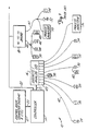
- Figure 1 is a diagram of a prior art distributed control system.
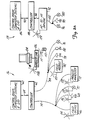
- Figure 2A is a diagram of an industrial plant having two distributed control systems and shows three embodiments of the present invention.
- Figure 2B is a diagram of industrial plant having two distributed control systems and shows three embodiments of the present invention.
- Figure 3 is a diagram of an industrial plant having an older analog distributed control system that has been retrofitted with newer network-based field devices and shows an embodiment of the present invention.
- FIG. 1 is a block diagram of a prior art distributed control system (DCS) 10.
- DCS 10 is comprised of control room 12, controller 14, discrete/analog I/O unit 16, H2-to-H1 bridge 18, and a variety of field devices represented by solenoid 24, switches 26 and 54, valve positioners 28, 46, and 52, transmitters 30, 34, and 44, process analyzers 36 and 50. These devices represent any type of field device known in the control art.
- handheld units 38 and 39 which are capable of accessing information in a hybrid or Fieldbus-based field device via a physical wire connection, and a local operator/user station 40, which is capable of issuing and receiving control room-type commands to and from the field device to which it is connected via a physical wire connection.
- Control room 12 includes computers, user I/O, various forms of data storage devices, and other computing devices known in the art.
- Control room 12 is coupled to controller 14 via bus 20, which is typically a proprietary digital communications network or an open digital communication network employing a proprietary protocol.
- Controller 14 receives various commands from control room 12 and provides data to control room 12.
- DCS 10 is a hybrid system comprising two different types of field devices.
- Devices 24 - 36 are traditional analog, discrete, and hybrid analog/digital devices, wherein the primary control function of the device is realized by modulating a current.
- These field devices are coupled to discrete/analog I/O unit 16, with each device connected to an individual channel of unit 16 by a single pair of wires (and possibly two additional power wires in the case of a traditional four-wire field device).
- solenoid 24 is coupled via two-wire twisted pair 42 to channel 43 of unit 16.
- the only communication with the device occurs by modulating or switching the current running through the two-wire twisted pair, with the magnitude of the current representing a measured process variable (as in the case of the transmitter), or an action requested by controller 14 (as in the case of a valve positioner or solenoid).
- Traditional analog devices have a frequency response limited to approximately 10 Hz and receive power from the two-wire twisted pair.
- Hybrid analog/digital devices operate in a manner similar to traditional analog devices, but also allow digital communication of secondary information by superimposing a digital carrier signal on the modulated current carried by the two-wire twisted pair.
- One such hybrid analog/digital system is known in the control art as Highway Addressable Remote Transducer (HART) and transmits data in a manner similar to a conventional computer modem adhering to the Bell 202 specification.
- HART Highway Addressable Remote Transducer
- the primary function of these devices is still realized by modulating the current through the loop, while other types of secondary information, such as diagnostic data, operating temperature, identification codes, error codes, and secondary variables, are transmitted digitally. In such a system, digital communication is relatively slow and is limited to approximately 300 baud.
- the maintenance person When a maintenance person desires to test an analog device, the maintenance person must make a physical connection to the device itself, such as local operator/user station 40 connected to transmitter 30, or to the two-wire twisted pair leading to the device, such as handheld unit 38 connected to the two-wire twisted pair leading to valve positioner 28.
- the device itself, such as local operator/user station 40 connected to transmitter 30, or to the two-wire twisted pair leading to the device, such as handheld unit 38 connected to the two-wire twisted pair leading to valve positioner 28.
- devices 44 - 54 are modern network-based digital field devices, wherein all information is digitally transmitted to and from each device. While many control system manufacturers have developed proprietary digital systems, the Standards and Practices Subcommittee 50 of the Instrument Society of America has developed and specified an architecture known in the art as Fieldbus.
- the Fieldbus specification includes two types of networks, a lower speed network referred to as H1 and a higher speed network referred to as H2. Both networks can support multiple connections to a single network bus, in contrast to traditional analog connections, which only support one device per two-wire twisted pair. While the present embodiments are described herein with reference to a Fieldbus network-based control system, in other embodiments the present invention may be employed in any distributed control system having network-based field devices.
- a Fieldbus H2 network can transmit data at a rate up to 2.5 megabits per second.
- an H2 network is redundant, with two sets of physical wire media comprising the network. Should the primary wire media fail, the secondary wire media is automatically used by the DCS. Because of the high capacity and redundancy of H2 Fieldbus networks, H2 Fieldbus networks are beginning to be used as a distribution network that connect the controller to various distribution units in the DCS. However, traditional distribution networks are proprietary networks using either parallel or serial communication.
- H2 distribution network 22 couples controller 14 to H2-to-H1 bridge 18, and proprietary bus 21 couples controller 14 to discrete/analog I/O unit 16.
- unit 16 and bridge 18 may be coupled to a common distribution network.
- discrete/analog I/O unit 16 includes discrete channels, with each channel coupled to a single device.
- H2-to-H1 bridge links the data carried by proprietary distribution network 22 to H1 Fieldbus control networks 45 and 47.
- H1 Fieldbus control network 45 is coupled to transmitters 44, valve positioner 46, and relay 48, and H1 Fieldbus 47 is coupled to process analyzer 50, valve positioner 52, and solenoid 54.
- H1 Fieldbus network is not redundant, and has a lower data transmission rate of approximately 31.25 kilobits per second, it is capable of providing power to the devices to which it is coupled, while an H2 Fieldbus network does not.
- the H1 Fieldbus network is ideal for providing final connections to individual field devices, while the H2 Fieldbus network is ideal for distributing control signals throughout the physical plant in which the DCS is installed.
- field devices have been provided in the prior art with microprocessors and additional functionality. Such "smart" field devices are capable of monitoring a plurality of process variables, performing a variety of control functions, performing comprehensive diagnostics, and providing a wide array of various types of status information.
- the Fieldbus specification specifies a variety of functions that may be supported by various Fieldbus field devices.
- many manufacturers have provided secondary functions beyond those specified in the Fieldbus specification. While Fieldbus field devices manufactured by different manufacturers are compatible to the extent that only Fieldbus specified functions are accessed, they are not compatible with respect to the secondary functions. For example, a Fieldbus controller manufactured by company A will generally not be able to access the secondary functions provided by a Fieldbus valve positioner manufactured by company B. Therefore, an industrial plant using a variety of Fieldbus components provided by different manufacturers will not be able to derive the benefit of all the functions provided by the various components.
- FIG. 2 is a diagram of an industrial plant having two distributed control systems.
- DCS 56 is comprised of control room 60, controller 62, bus 64, field device 66, valve positioner 68, transmitter 70, process analyzer 72, H1 Fieldbus control network 74, transmitter 76, valve positioner 78, solenoid 80, field module 82, and H1 Fieldbus control network 84.
- DCS 58 is comprised of control room 86, controller 88, bus 90, H2 Fieldbus distribution network 94, H2-to-H1 bridge 92, transmitters 96 and 100, valve positioner 98, and H1 Fieldbus control network 102.
- Buses 64 and 90 are normally proprietary digital communication networks, or open communication networks employing a proprietary protocol.
- terminal 104 and handheld control unit 110 are also shown in Figure 2 .
- Terminal 104 is coupled to wireless link module 106, which in turn is connected to wireless transceiver 108.
- Handheld control unit 110 includes wireless transceiver 112.
- DCS 56 Two embodiments of the present invention are illustrated in DCS 56.
- the first embodiment is illustrated by those field devices coupled to H1 Fieldbus control network 74.
- Each field device on control network 74 includes a wireless transceiver.
- Field device 66 represents any generic field device coupled to control network 74 and includes wireless transceiver 114.
- Valve positioner 68 includes wireless transceiver 116
- transmitter 70 includes wireless transceiver 118
- process analyzer 72 includes wireless transceiver 120.
- Each wireless transceiver implements a wireless Fieldbus connection with terminal 104 and handheld unit 110, thereby allowing access to secondary functions of each field device not accessible by control room 60, as well as providing a maintenance person with convenient access to each field device without having to communicate with the control room and independent of the distributed control system.
- the wireless Fieldbus connections described herein are implemented by secondary wireless network ports that are used in addition to primary network ports that are hardwired to a control room. Accordingly, a network-based field device may alternately be accessed via either the hardwired connection to the control room or the wireless Fieldbus connection.
- many prior art network-based field devices are provided with a redundant hardwired network connection that is used as a backup if the first connection fails.
- the field device is generally not alternately accessed by either the first or redundant connections, except for testing the redundant connection.
- typically the redundant connection is also routed to the control room.
- the wireless Fieldbus port attached to each field device is powered by the hardwired H1 Fieldbus port attached to each device. Therefore, a customer having Fieldbus control equipment from one manufacturer can connect field devices having a wireless Fieldbus port (in accordance with the present invention) to an existing H1 Fieldbus control network, and can access all the functions of the added field devices using a handheld unit having a wireless Fieldbus link, or a terminal having a wireless Fieldbus link. Since the wireless Fieldbus link of the field devices is powered by the existing H1 Fieldbus control network, no additional wiring is required.
- wireless links disclosed herein represent any wireless communication method known in the art, including, but not limited to, radio, infrared, visible light, and ultrasonic forms of wireless communication.
- a second embodiment of the present invention is illustrated by the devices connected to H1 Fieldbus control network 84.
- Transmitter 76, valve positioner 78, and solenoid 80 are each coupled to control network 84.
- field module 82 which includes a wireless transceiver 122 powered by H1 Fieldbus control network 84.
- Field module 82 in essence, forms a wireless bridge between control network 84 and handheld unit 110 or terminal 104, and allows unit 110 or terminal 104 to access each device coupled to H1 Fieldbus control network 84. Accordingly, field module 82 is ideally suited for use in an existing environment having a variety of H1 Fieldbus devices from different manufacturers. Handheld unit 110 and terminal 104 can easily be programmed to access the functions of each device on the control network to which field module 82 is connected.
- a third embodiment of the present invention is illustrated by DCS 58.
- controller 88 is coupled to H2-to-H1 bridge by H2 Fieldbus distribution network 94.
- H2-to-H1 bridge links H2 Fieldbus distribution network 94 to H1 Fieldbus control network 102.
- H2-to-H1 bridge also includes a second Fieldbus port connected to wireless transceiver 124, and communicates with a remote device such as handheld unit 110 or terminal 104. Accordingly, the remote wireless field device can access all field devices serviced by the H2-to-H1 bridge, such as transmitters 96 and 100 and valve positioner 98.
- it is common for an H2-to-H1 bridge to service a plurality of H1 Fieldbus control networks, in which case all field devices connected to all control networks serviced by the H2-to-H1 bridge can be accessed remotely.
- a maintenance person can walk from DCS to DCS with a single handheld control unit and access field devices coupled to each DCS. Since the handheld control unit can be programmed to access each field device, the maintenance person can access all the functions of devices supplied by different manufacturers.
- the present invention also provides a system for providing redundant wireless access to field devices in a distributed control system, thereby allowing access to field devices in the event of a failure of the hard-wired media that connects the field devices to a control room.
- the redundant wireless access can be used several ways. First, it can be used to allow continued operation of a distributed control system in the event of failure of or maintenance on the hard-wired media. However, even if continued operation is not desired, redundant wireless access may still be valuable for monitoring process variables and performing control actions, such as those required to shut down a process. For example, consider a distributed control system that is subjected to some sort of mishap, such as an explosion. The explosion, may vary well render the hard-wired media connecting field devices to the control room inoperable.
- a control room operator Using the redundant wireless access provided by the present invention, a control room operator will still be able to access field device to perform an orderly shutdown of the distributed control system.
- the operator may observe critical temperatures and pressures, and adjust or close valves and other devices to complete the shut down.
- the operator may be able to effect a shutdown in such a way as to minimize losses.
- FIG. 2B is a diagram of an industrial plant having two distributed control systems similar to Figure 2A and wherein the same components have the same reference numerals.
- DCS 56 in Figure 2B is comprised of control room 60 (which now includes terminal 104 coupled to wireless link module 106, which in turn is connected to wireless transceiver 108), controller 62, bus 64, field device 66, etc., as described for Figure 2A.
- DCS 58 is comprised of control room 86 (which now includes terminal 103 coupled to wireless link module 107, which in turn is connected to wireless transceiver 109), controller 88, bus 90, etc., as described for Figure 2A.
- DCS 56 Two embodiments of the invention of Figure 2B are illustrated in DCS 56.
- the first embodiment is illustrated by those field devices coupled to H1 Fieldbus control network 74.
- Each field device on control network 74 includes a wireless transceiver.
- Each wireless transceiver implements a redundant wireless Fieldbus connection with terminal 104, thereby allowing redundant wireless access to each field device from control room 60.
- a second embodiment of the invention of Figure 2B is illustrated by the devices connected to H1 Fieldbus control network 84.
- Transmitter 76, valve positioner 78, and solenoid 80 are each coupled to control network 84.
- field module 82 which includes a wireless transceiver 122 powered by H1 Fieldbus control network 84.
- Field module 82 in essence, forms a wireless bridge between control network 84 and terminal 104 in control room 56, and allows terminal 104 to access each device coupled to H1 Fieldbus control network 84. Accordingly, field module 82 is ideally suited for providing redundant wireless access in an existing environment having a variety of H1 Fieldbus devices from different manufacturers.
- a third embodiment of the invention of Figure 2B is illustrated by DCS 58.
- controller 88 is coupled to H2-to-H1 bridge by H2 Fieldbus distribution network 94.
- H2-to-H1 bridge links H2 Fieldbus distribution network 94 to H1 Fieldbus control network 102.
- H2-to-H1 bridge also includes a second Fieldbus port connected to wireless transceiver 124, and communicates with a remote device such as terminal 103. Accordingly, terminal 103 in control room 86 can access all field devices serviced by the H2-to-H1 bridge, such as transmitters 96 and 100 and valve positioner 98.
- FIG. 3 shows an embodiment of the present invention adapted for use in older distributed control systems that have been retrofitted with newer Fieldbus field devices.
- DCS 126 includes control room 128, controller 130, bus 132, discrete/analog I/O unit 134, bridge/converter 136, bus 137, H1 Fieldbus control networks 138 and 140, solenoids 142 and 152, transmitters 144 and 148, valve positioner 146 and 150, handheld unit 154, and terminal 156.
- DCS 126 represents an older distributed control system designed for use with traditional discrete analog/discrete and hybrid field devices. With the exception of terminal 156, everything above dotted line 158 represents components that are part of an older existing installation. Everything below dotted line 158 (and terminal 156) represent newer Fieldbus components that have been added to the installation.
- Bridge/converter 136 interfaces the older portion of DCS 126 (above dotted line 158) to the Fieldbus devices.
- Bridge/converter 136 includes a plurality of process I/O channels (such as channel 160) that are coupled to corresponding process I/O channels of discrete/analog I/O unit 134 (such as channel 162) by two-wire twisted pairs (such as two-wire twisted pair 164).
- Bridge/converter 136 converts the analog, discrete, and/or hybrid information provided by discrete/analog I/O unit 134 into digital information that is transmitted to devices on H1 Fieldbus networks 138 and 140, and converts the digital information received from devices on networks 138 and 140 into analog, discrete, and/or hybrid information required by discrete/analog I/O unit 134.
- control room 1208 From the viewpoint of control room 128, the Fieldbus field devices appear as traditional analog/discrete and hybrid field devices. Accordingly, control room 128 cannot access any of the secondary functions provided by the Fieldbus field devices. To access these functions, bridge/converter 136 is provided with an active hard-wired Fieldbus port 166 and wireless Fieldbus port 168.
- Hard-wired Fieldbus port 166 is connected to Fieldbus network 170, which in turn is connected to terminal 156.
- terminal 156 is located within control room 128, and provides operators within the control room with access to all the functions that are provided by the Fieldbus field devices, and are not accessible through existing control room components.
- Port 166 is not a redundant port, rather it is a secondary port that provides the control room with access to all the functions provided by the Fieldbus based devices. Accordingly, a control room operator may alternately access a Fieldbus based device via discrete/analog I/O unit 134, or terminal 156.
- a redundant port is used as a backup if the first port fails. In the configuration shown in Figure 3, a redundant port would not be coupled to the control room.
- Fieldbus port 168 is connected to wireless transceiver 172, thereby forming a wireless Fieldbus network similar to the wireless Fieldbus networks shown in Figure 2.
- Handheld unit 154 has wireless transceiver 174, and communicates with Fieldbus devices 142 - 152 via wireless transceiver 172, which is connected to wireless port 168 of bridge/converter 136.
- a terminal having a wireless link (such as terminal 104 and wireless link 106 in Figure 2) may be used to communicate with the field devices coupled to bridge/converter 136.
- the present invention provides an apparatus for providing secondary access to field devices in a distributed control system having a control room for providing primary access to the field devices.
- a modern distributed control system having Fieldbus devices coupled to a Fieldbus control room the present invention provides a wireless link to a remote unit, such as a handheld device or a terminal having a wireless link, thereby allowing a maintenance person to access each Fieldbus device in the field via the remote unit. Since a Fieldbus control room from one manufacturer may not be able to access secondary functions of a Fieldbus device from another manufacturer, the handheld unit can also provide a convenient way to access secondary functions provided by various manufacturers from a single, easily programmed handheld unit or remote terminal.
- the present invention also provides an apparatus for providing wireless redundant access to field devices in a distributed control system having a control room that provides hard-wired access to the field devices.
- a distributed control system having Fieldbus devices coupled to a Fieldbus control room the present invention provides a redundant wireless to a terminal having a wireless link.
- the apparatus of the present invention allows access to field devices in the event of failure or other unavailability of the hard-wired media that couples the control room to field devices, which is the primary way of accessing the control devices.
- each Fieldbus-based device is provided with its own secondary wireless H1 or H2 Fieldbus port that is powered by the H1 Fieldbus control network.
- This embodiment provides maximum flexibility because no modification of the distributed control system is required, and is ideally suited for new devices that are to be added to an existing Fieldbus installation. As soon as the H1 Fieldbus device is connected to the existing H1 Fieldbus control network, the device can be accessed via the wireless handheld unit or the wireless terminal.
- a field module is connected to an existing Fieldbus control network.
- the field module has a wireless H1 or H2 Fieldbus port that is powered by the H1 Fieldbus control network, and provides access from the wireless handheld unit or the wireless terminal to all Fieldbus devices connected to the control network.
- This embodiment is ideally suited for distributed control systems that already have Fieldbus devices.
- the distributed control system is provided with an H2-to-H1 bridge having one or more H1 control networks coupled to Fieldbus devices, a hard-wired H2 port coupled to a controller, and a wireless H2 or H1 Fieldbus port.
- the wireless Fieldbus port allows a wireless handheld unit or a wireless terminal to access all Fieldbus devices on all H1 control networks serviced by the H2-to-Hl bridge.
- a bridge/converter is connected to the two-wire twisted pair analog/discrete and hybrid wires coming from an older control room, and couples the older control room to newer Fieldbus devices.
- the bridge/converter provides an H1 or H2 Fieldbus port to allow access to functions of the Fieldbus devices not accessible from the control room.
- a terminal is connected to the bridge/converter via a hard-wire Fieldbus network. The terminal, which may be placed in the control room, provides the operators of the control system with access to all functions of the Fieldbus-based devices.
- the bridge/converter is provided with a wireless H1 or H2 Fieldbus port that allows the Fieldbus field devices to be accessed by a wireless terminal or a wireless handheld unit.
Abstract
Description
Claims (16)
- A distributed control system comprising:characterized bya control room (60, 86) for providing primary control of the distributed control system;a plurality of network based field devices (66 - 72), with each network based field device having a primary control network port;a control network (74, 84, 94) coupled to each primary control network port of each network-based field device (66 - 72) of the plurality of network-based field devices;a controller (62, 88) coupled to the control room (60, 86), for controlling and providing primary access to primary functions of the plurality of network based field devices (66 - 72);network/controller connection means (92, 134, 136) for connecting the control network (74, 84, 94) to the controller (62, 88);secondary access means (114 - 120) for providing non-redundant wireless secondary access to secondary functions of the plurality of network-based field devices (66 - 72), anda wireless terminal (104) or handheld unit (110) for implementing wireless access to secondary functions of each field device (66 - 72).
- The distributed control system of Claim 1 wherein the secondary access means comprises:a wireless transceiver (114) coupled to a non-redundant secondary port of each of the plurality of network-based field devices (66 - 72).
- The distributed control system of Claim 2 wherein the wireless transceiver (114) is connected to receive power from the control network (74) via the primary control network port.
- The distributed control system of claim 1 wherein the secondary access means comprises a field module (82) coupled to the control network (84), the field module comprising a first network port coupled to the control network (84) ; a non-redundant secondary port; and a wireless transceiver (122) coupled to the non-redundant secondary port.
- The distributed control system of Claim 4 wherein the field module (82) is connected to power from the control network (84) via the first network port.
- The distributed control system of Claim 1 wherein the controller (88) is coupled to a distribution network (94), and the network/controller connection means comprises a bridge for transmitting information from the distribution network (94) to the control network (102), the bridge including a first port coupled to the distribution network (94); a second port coupled to the control network (102); a wireless transceiver (124); and a third non-redundant port coupled to the wireless transceiver (124).
- The distributed control system of claim 1 wherein the network/controller connection means comprises:a discrete/analog I/O unit (134) including a bus (137) coupled to the controller (130); and a plurality of discrete/analog I/O channels (162), and a bridge/converter (136) including a plurality of discrete/analog I/O channels (160) coupled to the plurality of analog I/O channels (162) of the discrete analog I/O unit (134) ; a non-redundant network-based field device access port (168) for providing access to functions of the plurality of network-based field devices (142 - 152) not accessible via the controller (130) ; and a control network port coupled to the control network (138, 140).
- The distributed control system of Claim 7 further comprising a terminal (156) ; and a hard-wired connection (170) between the terminal and the non-redundant network-based field device access port (166) of the bridge/converter (136).
- The distributed control system of Claim 7, further comprising a wireless transceiver (172) coupled to the non-redundant network-based field device access port (168) of the bridge/converter; and a remote access device (14) having a wireless transceiver (174), for remotely accessing the plurality of network-based field devices (142 - 152).
- The distributed control system of any one of the Claims 1 to 9, wherein each network-based field device comprises control means (66 - 72) for implementing a control function; said primary control network port for providing primary control access to the network-based field device (66 - 72); and a non-redundant secondary port for providing non-redundant secondary access to the network-based field device.
- The distributed control system of Claim 10 wherein the network-based field device implements a set of functions, with the subset of secondary functions accessible via the non-redundant secondary port and not accessible via the primary control network port.
- The distributed control system of Claim 4 or 5 wherein the field module (82) facilitates access to the subset of secondary functions implemented by field devices connected to a control network, and the subset of secondary functions cannot be accessed by a controller (62) coupled to the control network (84).
- The distributed control system of Claim 6 wherein the bridge (92) facilitates access to a subset of secondary functions implemented by field devices connected to a control network (102), and the subset of secondary functions cannot be accessed by a controller (88) coupled to the distribution network (90).
- A distributed control system comprising a control room (60, 86) for providing primary control of the distributed control system via hard-wired media;characterized bya plurality of network-based field devices (66 - 72), with each network based field device having a primary control network port;a control network (74, 84, 94) coupled to each primary control network port of each network-based field device of the plurality of network-based field devices (66 - 72);a controller (62, 88) coupled to the control room (60, 86), for controlling and providing primary access to primary functions of the plurality of network-based field devices (66 - 72);network/controller connection means (92, 134, 136) for connecting the control network to the controller (60, 86);secondary access means (114 - 120) for providing redundant wireless access to the same functions of the plurality of network-based field devices (66 - 72); anda wireless terminal (103, 104) coupled to a wireless link (106, 107) in the control room (60, 86).
- The distributed control system of Claim 14 wherein the secondary access means further comprises a first wireless transceiver (124, 172) configured to provide non-wireless access to the plurality of network-based devices (96 - 100, 142 - 152); and a remote access device (154) having a second wireless transceiver (174), for remotely accessing the plurality of network-based field devices via the first wireless transceiver (124, 172).
- The distributed control system of Claim 14 or 15 wherein the secondary access means comprises a remote terminal (156) configured to provide non-wireless access to the plurality of networked based devices.
Priority Applications (1)
| Application Number | Priority Date | Filing Date | Title |
|---|---|---|---|
| EP99108765A EP0940738B1 (en) | 1994-10-24 | 1995-10-20 | Field devices for use in a distributed control system |
Applications Claiming Priority (5)
| Application Number | Priority Date | Filing Date | Title |
|---|---|---|---|
| US32832494A | 1994-10-24 | 1994-10-24 | |
| US328324 | 1994-10-24 | ||
| US48311995A | 1995-06-07 | 1995-06-07 | |
| US483119 | 1995-06-07 | ||
| PCT/US1995/013150 WO1996012993A1 (en) | 1994-10-24 | 1995-10-20 | Apparatus for providing access to field devices in a distributed control system |
Related Child Applications (1)
| Application Number | Title | Priority Date | Filing Date |
|---|---|---|---|
| EP99108765A Division EP0940738B1 (en) | 1994-10-24 | 1995-10-20 | Field devices for use in a distributed control system |
Publications (2)
| Publication Number | Publication Date |
|---|---|
| EP0788627A1 EP0788627A1 (en) | 1997-08-13 |
| EP0788627B1 true EP0788627B1 (en) | 1999-12-15 |
Family
ID=26986316
Family Applications (2)
| Application Number | Title | Priority Date | Filing Date |
|---|---|---|---|
| EP95937438A Expired - Lifetime EP0788627B1 (en) | 1994-10-24 | 1995-10-20 | Apparatus for providing access to field devices in a distributed control system |
| EP99108765A Expired - Lifetime EP0940738B1 (en) | 1994-10-24 | 1995-10-20 | Field devices for use in a distributed control system |
Family Applications After (1)
| Application Number | Title | Priority Date | Filing Date |
|---|---|---|---|
| EP99108765A Expired - Lifetime EP0940738B1 (en) | 1994-10-24 | 1995-10-20 | Field devices for use in a distributed control system |
Country Status (14)
| Country | Link |
|---|---|
| US (8) | US5682476A (en) |
| EP (2) | EP0788627B1 (en) |
| JP (2) | JP3859015B2 (en) |
| KR (1) | KR100401558B1 (en) |
| CN (1) | CN1148620C (en) |
| AT (1) | ATE187824T1 (en) |
| BR (1) | BR9509503A (en) |
| CA (1) | CA2203561C (en) |
| DE (2) | DE69514001T2 (en) |
| FI (1) | FI115079B (en) |
| NO (1) | NO317025B1 (en) |
| NZ (1) | NZ295900A (en) |
| TW (1) | TW280883B (en) |
| WO (1) | WO1996012993A1 (en) |
Cited By (4)
| Publication number | Priority date | Publication date | Assignee | Title |
|---|---|---|---|---|
| DE10026033C2 (en) * | 2000-05-25 | 2003-05-28 | Abb Patent Gmbh | Transmitter with a flameproof encapsulated transmitter housing |
| US7620463B2 (en) | 2003-09-25 | 2009-11-17 | Siemens Aktiengesellschaft | Arrangement for the transmission of data |
| EP2306648A1 (en) | 2009-10-02 | 2011-04-06 | Siemens Aktiengesellschaft | Duplex data transfer via portable electronic device and field device |
| US8125405B2 (en) | 1999-02-12 | 2012-02-28 | Fisher-Rosemount Systems, Inc. | Wearable computer in a process control environment |
Families Citing this family (329)
| Publication number | Priority date | Publication date | Assignee | Title |
|---|---|---|---|---|
| BR9509503A (en) * | 1994-10-24 | 1997-12-30 | Fisher Rosemount Systems Inc | Networked field device distributed control system bridge field module designed to transmit information from a distribution network to a bridge / converter control network |
| DE19521992A1 (en) | 1995-06-20 | 1997-01-02 | Bosch Gmbh Robert | Method for generating a stream of image data for the transmission of an image and method for evaluating a stream of image data |
| US7623932B2 (en) * | 1996-03-28 | 2009-11-24 | Fisher-Rosemount Systems, Inc. | Rule set for root cause diagnostics |
| US8290721B2 (en) | 1996-03-28 | 2012-10-16 | Rosemount Inc. | Flow measurement diagnostics |
| US7630861B2 (en) * | 1996-03-28 | 2009-12-08 | Rosemount Inc. | Dedicated process diagnostic device |
| US5862052A (en) * | 1996-04-12 | 1999-01-19 | Fisher-Rosemount Systems, Inc. | Process control system using a control strategy implemented in a layered hierarchy of control modules |
| US6098116A (en) * | 1996-04-12 | 2000-08-01 | Fisher-Rosemont Systems, Inc. | Process control system including a method and apparatus for automatically sensing the connection of devices to a network |
| US6032208A (en) * | 1996-04-12 | 2000-02-29 | Fisher-Rosemount Systems, Inc. | Process control system for versatile control of multiple process devices of various device types |
| US5850523A (en) * | 1996-06-21 | 1998-12-15 | National Instruments Corporation | Method and system for monitoring fieldbus network with multiple packet filters |
| EP0825506B1 (en) | 1996-08-20 | 2013-03-06 | Invensys Systems, Inc. | Methods and apparatus for remote process control |
| US7146230B2 (en) * | 1996-08-23 | 2006-12-05 | Fieldbus Foundation | Integrated fieldbus data server architecture |
| US6424872B1 (en) | 1996-08-23 | 2002-07-23 | Fieldbus Foundation | Block oriented control system |
| US20040194101A1 (en) * | 1997-08-21 | 2004-09-30 | Glanzer David A. | Flexible function blocks |
| DE69710201T3 (en) * | 1996-10-04 | 2007-07-05 | Fisher Controls International Llc (N.D.Ges.D.Staates Delaware) | NETWORK ACCESS INTERFACE FOR PROCESS CONTROL NETWORK |
| US6047222A (en) * | 1996-10-04 | 2000-04-04 | Fisher Controls International, Inc. | Process control network with redundant field devices and buses |
| BR9711589A (en) | 1996-10-04 | 1999-08-24 | Fisher Controls Int | Maintenance interface device for use in a process control system |
| US6044305A (en) * | 1996-10-04 | 2000-03-28 | Fisher Controls International, Inc. | Method and apparatus for debugging and tuning a process control network having distributed control functions |
| CA2267526C (en) * | 1996-10-04 | 2006-08-01 | Fisher Controls International, Inc. | Process control network with redundant field devices and busses |
| US5970430A (en) * | 1996-10-04 | 1999-10-19 | Fisher Controls International, Inc. | Local device and process diagnostics in a process control network having distributed control functions |
| CN1169032C (en) * | 1996-11-29 | 2004-09-29 | 松下电工株式会社 | Building automation system |
| US8982856B2 (en) | 1996-12-06 | 2015-03-17 | Ipco, Llc | Systems and methods for facilitating wireless network communication, satellite-based wireless network systems, and aircraft-based wireless network systems, and related methods |
| US7054271B2 (en) | 1996-12-06 | 2006-05-30 | Ipco, Llc | Wireless network system and method for providing same |
| DE69736680T2 (en) * | 1997-02-07 | 2007-10-11 | Mitsubishi Denki K.K. | SYSTEM AND DEVICE FOR BUS CONTROL |
| US5980078A (en) * | 1997-02-14 | 1999-11-09 | Fisher-Rosemount Systems, Inc. | Process control system including automatic sensing and automatic configuration of devices |
| US6061604A (en) * | 1997-05-06 | 2000-05-09 | Gas Research Institute | RF base repeater for automated residence management system |
| DE19720517A1 (en) * | 1997-05-16 | 1998-11-19 | Fischer Gmbh Gert | Method and device for generating and outputting a secondary message as a function of a selectively acquired primary message |
| FR2765364B1 (en) * | 1997-06-26 | 1999-08-06 | Air Liquide | REMOTE MONITORING INSTALLATION OF A PARK OF HETEROGENEOUS EQUIPMENT OF INDUSTRIAL PRODUCTION |
| JPH1144524A (en) * | 1997-07-28 | 1999-02-16 | Matsushita Electric Ind Co Ltd | Electronic part-mounting device using surface-mounting type package and inspection method thereof |
| US6999824B2 (en) * | 1997-08-21 | 2006-02-14 | Fieldbus Foundation | System and method for implementing safety instrumented systems in a fieldbus architecture |
| US6014612A (en) * | 1997-10-02 | 2000-01-11 | Fisher Controls International, Inc. | Remote diagnostics in a process control network having distributed control functions |
| DE19743981C2 (en) * | 1997-10-06 | 1999-11-25 | Ifm Electronic Gmbh | Method for assigning addresses to an actuator-sensor-interface-slave as well as actuator-sensor-interface-slave and address programming device for carrying out the method |
| DE69818494T2 (en) * | 1997-10-13 | 2004-07-01 | Rosemount Inc., Eden Prairie | Transmission method for field devices in industrial processes |
| US6088665A (en) * | 1997-11-03 | 2000-07-11 | Fisher Controls International, Inc. | Schematic generator for use in a process control network having distributed control functions |
| US6104875A (en) * | 1997-12-18 | 2000-08-15 | Honeywell Inc. | Method for field programming an industrial process transmitter |
| EP1060552B1 (en) * | 1998-03-06 | 2002-10-02 | ABBPATENT GmbH | Field bus system with a field bus distributor |
| WO1999053627A1 (en) | 1998-04-10 | 1999-10-21 | Chrimar Systems, Inc. Doing Business As Cms Technologies | System for communicating with electronic equipment on a network |
| US6691183B1 (en) | 1998-05-20 | 2004-02-10 | Invensys Systems, Inc. | Second transfer logic causing a first transfer logic to check a data ready bit prior to each of multibit transfer of a continous transfer operation |
| FI114745B (en) * | 1998-06-01 | 2004-12-15 | Metso Automation Oy | Control systems for field devices |
| DE19851245B4 (en) * | 1998-06-12 | 2005-05-25 | Phoenix Contact Gmbh & Co. Kg | Fieldbus component, communication system and method for transmitting data over a high-speed transmission medium |
| US6891838B1 (en) | 1998-06-22 | 2005-05-10 | Statsignal Ipc, Llc | System and method for monitoring and controlling residential devices |
| US8410931B2 (en) | 1998-06-22 | 2013-04-02 | Sipco, Llc | Mobile inventory unit monitoring systems and methods |
| US6914893B2 (en) | 1998-06-22 | 2005-07-05 | Statsignal Ipc, Llc | System and method for monitoring and controlling remote devices |
| US6437692B1 (en) | 1998-06-22 | 2002-08-20 | Statsignal Systems, Inc. | System and method for monitoring and controlling remote devices |
| FR2783615B1 (en) * | 1998-09-18 | 2000-10-13 | Cegelec Sa | ARRANGEMENT FOR THE INDIVIDUAL CONTROL OF AN ACTUATOR OF A HIGH SECURITY INDUSTRIAL INSTALLATION |
| US6272398B1 (en) | 1998-09-21 | 2001-08-07 | Siebolt Hettinga | Processor-based process control system with intuitive programming capabilities |
| US7640007B2 (en) * | 1999-02-12 | 2009-12-29 | Fisher-Rosemount Systems, Inc. | Wireless handheld communicator in a process control environment |
| US6806847B2 (en) * | 1999-02-12 | 2004-10-19 | Fisher-Rosemount Systems Inc. | Portable computer in a process control environment |
| SE9900510D0 (en) * | 1999-02-15 | 1999-02-15 | Iro Patent Ag | Yarn processing system and method to operate a yarn processing system |
| US6510351B1 (en) | 1999-03-15 | 2003-01-21 | Fisher-Rosemount Systems, Inc. | Modifier function blocks in a process control system |
| US7650425B2 (en) | 1999-03-18 | 2010-01-19 | Sipco, Llc | System and method for controlling communication between a host computer and communication devices associated with remote devices in an automated monitoring system |
| ATE297563T1 (en) * | 1999-03-18 | 2005-06-15 | Wolfgang Rothengass | DEVICE FOR CONTROLLING ANY FUNCTIONAL EQUIPMENT IN THE HOUSE |
| WO2000070531A2 (en) | 1999-05-17 | 2000-11-23 | The Foxboro Company | Methods and apparatus for control configuration |
| US6754885B1 (en) | 1999-05-17 | 2004-06-22 | Invensys Systems, Inc. | Methods and apparatus for controlling object appearance in a process control configuration system |
| US7089530B1 (en) | 1999-05-17 | 2006-08-08 | Invensys Systems, Inc. | Process control configuration system with connection validation and configuration |
| US6788980B1 (en) | 1999-06-11 | 2004-09-07 | Invensys Systems, Inc. | Methods and apparatus for control using control devices that provide a virtual machine environment and that communicate via an IP network |
| US6978294B1 (en) * | 2000-03-20 | 2005-12-20 | Invensys Systems, Inc. | Peer-to-peer hosting of intelligent field devices |
| US6501995B1 (en) | 1999-06-30 | 2002-12-31 | The Foxboro Company | Process control system and method with improved distribution, installation and validation of components |
| US6510352B1 (en) | 1999-07-29 | 2003-01-21 | The Foxboro Company | Methods and apparatus for object-based process control |
| US6618745B2 (en) | 1999-09-10 | 2003-09-09 | Fisher Rosemount Systems, Inc. | Linking device in a process control system that allows the formation of a control loop having function blocks in a controller and in field devices |
| US6711629B1 (en) | 1999-10-18 | 2004-03-23 | Fisher-Rosemount Systems, Inc. | Transparent support of remote I/O in a process control system |
| US6574681B1 (en) * | 1999-10-21 | 2003-06-03 | H. Philip White | Network platform for field devices |
| US6473660B1 (en) * | 1999-12-03 | 2002-10-29 | The Foxboro Company | Process control system and method with automatic fault avoidance |
| EP1247240B1 (en) * | 2000-01-06 | 2008-07-30 | Rapp, Roy W., III | A paperless tablet automation apparatus and method |
| US6400997B1 (en) * | 2000-01-06 | 2002-06-04 | Roy Rapp, III | Paperless tablet automation apparatus and method |
| DE10000609B4 (en) * | 2000-01-10 | 2006-04-13 | Gira Giersiepen Gmbh & Co. Kg | Interface device for a data connection between an electrical installation system and a Komminikationssystem and equipped therewith electrical installation system |
| US6779128B1 (en) | 2000-02-18 | 2004-08-17 | Invensys Systems, Inc. | Fault-tolerant data transfer |
| AU2001247413B2 (en) * | 2000-03-15 | 2005-08-25 | Invitrogen Corporation | High fidelity reverse transcriptases and uses thereof |
| US6898378B1 (en) | 2000-03-24 | 2005-05-24 | Northrop Grumman Corporation | Shock-resistant backplane utilizing infrared communication scheme with electrical interface for embedded systems |
| SE522377C2 (en) * | 2000-03-31 | 2004-02-03 | Kvaser Consultant Ab | Device for transmitting data and control commands via radio links in distributed control system for one or more machines and / or processes |
| US6842459B1 (en) | 2000-04-19 | 2005-01-11 | Serconet Ltd. | Network combining wired and non-wired segments |
| US20050240286A1 (en) * | 2000-06-21 | 2005-10-27 | Glanzer David A | Block-oriented control system on high speed ethernet |
| DE10032774A1 (en) * | 2000-07-06 | 2002-01-17 | Endress Hauser Gmbh Co | field device |
| DE10042165C1 (en) | 2000-08-17 | 2002-04-18 | Butzke Werke Aqua | System for controlling and monitoring sanitary fittings |
| DE60018072T2 (en) * | 2000-10-27 | 2005-12-29 | Invensys Systems, Inc., Foxboro | Field device with a transmitter and / or receiver for wireless data transmission |
| DE10053763C2 (en) * | 2000-10-30 | 2002-10-17 | Pilz Gmbh & Co | Fieldbus system for controlling safety-critical processes and bus interface module for use in such a fieldbus system |
| AU2002233990A1 (en) * | 2000-11-16 | 2002-05-27 | Invensys Systems, Inc. | Control system methods and apparatus for inductive communication across an isolation barrier |
| EP1346728A1 (en) * | 2000-11-22 | 2003-09-24 | Mitsubishi Pharma Corporation | Ophthalmological preparations |
| CH696253A5 (en) * | 2000-12-29 | 2007-02-28 | Sticht Fertigungstech Stiwa | Plant Betriebsleiteinrichtung for manufacturing and / or mounting device. |
| WO2002071171A2 (en) * | 2001-03-01 | 2002-09-12 | Fisher-Rosemount Systems, Inc. | Automatic work order/parts order generation and tracking |
| US6795798B2 (en) * | 2001-03-01 | 2004-09-21 | Fisher-Rosemount Systems, Inc. | Remote analysis of process control plant data |
| US6859755B2 (en) | 2001-05-14 | 2005-02-22 | Rosemount Inc. | Diagnostics for industrial process control and measurement systems |
| JP4157687B2 (en) * | 2001-06-11 | 2008-10-01 | 株式会社山武 | Field equipment |
| US7080065B1 (en) * | 2001-06-22 | 2006-07-18 | Oracle International Corporation | Query pruning using interior rectangles in an R-tree index |
| EP1288757A1 (en) * | 2001-08-07 | 2003-03-05 | Siemens Aktiengesellschaft | Method and process control system for operating a technical installation |
| EP1293853A1 (en) * | 2001-09-12 | 2003-03-19 | ENDRESS + HAUSER WETZER GmbH + Co. KG | Transceiver module for a field device |
| US7143149B2 (en) | 2001-09-21 | 2006-11-28 | Abb Ab | Dynamic operator functions based on operator position |
| FR2830962B1 (en) * | 2001-10-12 | 2004-01-30 | Inst Nat Rech Inf Automat | IMAGE PROCESSING DEVICE AND METHOD FOR DETECTION OF EVOLUTIVE LESIONS |
| US20040088448A1 (en) * | 2001-10-16 | 2004-05-06 | Userspace Corporation | Embedded system and method for controlling, monitoring of instruments or devices and processing their data via control and data protocols that can be combined or interchanged |
| US7480501B2 (en) | 2001-10-24 | 2009-01-20 | Statsignal Ipc, Llc | System and method for transmitting an emergency message over an integrated wireless network |
| US8489063B2 (en) | 2001-10-24 | 2013-07-16 | Sipco, Llc | Systems and methods for providing emergency messages to a mobile device |
| US7424527B2 (en) | 2001-10-30 | 2008-09-09 | Sipco, Llc | System and method for transmitting pollution information over an integrated wireless network |
| GB0127551D0 (en) * | 2001-11-16 | 2002-01-09 | Abb Ab | Analysing events |
| US20030229472A1 (en) * | 2001-12-06 | 2003-12-11 | Kantzes Christopher P. | Field maintenance tool with improved device description communication and storage |
| US6889166B2 (en) | 2001-12-06 | 2005-05-03 | Fisher-Rosemount Systems, Inc. | Intrinsically safe field maintenance tool |
| US7426452B2 (en) * | 2001-12-06 | 2008-09-16 | Fisher-Rosemount Systems. Inc. | Dual protocol handheld field maintenance tool with radio-frequency communication |
| US20030204373A1 (en) * | 2001-12-06 | 2003-10-30 | Fisher-Rosemount Systems, Inc. | Wireless communication method between handheld field maintenance tools |
| JP2003216231A (en) * | 2002-01-18 | 2003-07-31 | Hitachi Ltd | Field monitoring and operating device |
| US6973508B2 (en) | 2002-02-12 | 2005-12-06 | Fisher-Rosemount Systems, Inc. | Highly versatile process control system controller |
| US7035773B2 (en) * | 2002-03-06 | 2006-04-25 | Fisher-Rosemount Systems, Inc. | Appendable system and devices for data acquisition, analysis and control |
| FI116004B (en) * | 2002-03-11 | 2005-08-31 | Metso Automation Oy | Redundancy in process control system |
| US7027952B2 (en) | 2002-03-12 | 2006-04-11 | Fisher-Rosemount Systems, Inc. | Data transmission method for a multi-protocol handheld field maintenance tool |
| US7039744B2 (en) | 2002-03-12 | 2006-05-02 | Fisher-Rosemount Systems, Inc. | Movable lead access member for handheld field maintenance tool |
| WO2003089995A2 (en) | 2002-04-15 | 2003-10-30 | Invensys Systems, Inc. | Methods and apparatus for process, factory-floor, environmental, computer aided manufacturing-based or other control system with real-time data distribution |
| US6839546B2 (en) | 2002-04-22 | 2005-01-04 | Rosemount Inc. | Process transmitter with wireless communication link |
| US20030204371A1 (en) * | 2002-04-30 | 2003-10-30 | Chevron U.S.A. Inc. | Temporary wireless sensor network system |
| US7780526B2 (en) * | 2002-06-28 | 2010-08-24 | Igt | Universal system mediation within gaming environments |
| US20040149436A1 (en) * | 2002-07-08 | 2004-08-05 | Sheldon Michael L. | System and method for automating or metering fluid recovered at a well |
| DE10234467A1 (en) * | 2002-07-29 | 2004-02-19 | Siemens Ag | Process control method for an automated technical plant, in which commands issued by localized mobile control units are routed via the central control unit to prevent inadvertent issuing of commands to plant components |
| US6926440B2 (en) * | 2002-11-01 | 2005-08-09 | The Boeing Company | Infrared temperature sensors for solar panel |
| IL152824A (en) | 2002-11-13 | 2012-05-31 | Mosaid Technologies Inc | Addressable outlet and a network using same |
| DE10253603A1 (en) * | 2002-11-15 | 2004-06-03 | Endress + Hauser Conducta Gesellschaft für Mess- und Regeltechnik mbH + Co. KG | Method for generating software modules for field devices in process automation technology |
| DE10253572A1 (en) | 2002-11-15 | 2004-07-29 | Vega Grieshaber Kg | Wireless communication |
| US7574509B2 (en) * | 2002-11-25 | 2009-08-11 | Fisher-Rosemount Systems, Inc. | Interactive two-way collaboration in process control plants |
| DE10255741A1 (en) * | 2002-11-28 | 2004-06-09 | Endress + Hauser Conducta Gesellschaft für Mess- und Regeltechnik mbH + Co. KG | Modular transmitter with galvanically isolated sensor |
| US10261506B2 (en) | 2002-12-05 | 2019-04-16 | Fisher-Rosemount Systems, Inc. | Method of adding software to a field maintenance tool |
| US6934298B2 (en) | 2003-01-09 | 2005-08-23 | Modular Mining Systems, Inc. | Hot standby access point |
| JP4739183B2 (en) * | 2003-03-06 | 2011-08-03 | フィッシャー−ローズマウント システムズ, インコーポレイテッド | Battery |
| WO2004083974A1 (en) * | 2003-03-18 | 2004-09-30 | T.E.R Tecno Elettrica Ravasi S.R.L. | Integrated apparatus for use in industrial machinery |
| AU2004231988B2 (en) | 2003-04-16 | 2010-04-15 | Drexel University | Acoustic blood analyzer for assessing blood properties |
| US7512521B2 (en) * | 2003-04-30 | 2009-03-31 | Fisher-Rosemount Systems, Inc. | Intrinsically safe field maintenance tool with power islands |
| US7054695B2 (en) | 2003-05-15 | 2006-05-30 | Fisher-Rosemount Systems, Inc. | Field maintenance tool with enhanced scripts |
| US7036386B2 (en) | 2003-05-16 | 2006-05-02 | Fisher-Rosemount Systems, Inc. | Multipurpose utility mounting assembly for handheld field maintenance tool |
| US8874402B2 (en) | 2003-05-16 | 2014-10-28 | Fisher-Rosemount Systems, Inc. | Physical memory handling for handheld field maintenance tools |
| US7526802B2 (en) * | 2003-05-16 | 2009-04-28 | Fisher-Rosemount Systems, Inc. | Memory authentication for intrinsically safe field maintenance tools |
| US7199784B2 (en) | 2003-05-16 | 2007-04-03 | Fisher Rosemount Systems, Inc. | One-handed operation of a handheld field maintenance tool |
| US6925419B2 (en) * | 2003-05-16 | 2005-08-02 | Fisher-Rosemount Systems, Inc. | Intrinsically safe field maintenance tool with removable battery pack |
| US7460865B2 (en) | 2003-06-18 | 2008-12-02 | Fisher-Rosemount Systems, Inc. | Self-configuring communication networks for use with process control systems |
| US7436797B2 (en) * | 2003-06-18 | 2008-10-14 | Fisher-Rosemount Systems, Inc. | Wireless architecture and support for process control systems |
| IL157787A (en) | 2003-09-07 | 2010-12-30 | Mosaid Technologies Inc | Modular outlet for data communications network |
| DE10335429A1 (en) * | 2003-07-31 | 2005-02-24 | Siemens Ag | Field unit log generation method for use in an automation system whereby field unit data are requested from an automation system processing unit by a monitoring application running on a user data processing system and recorded |
| US7280048B2 (en) | 2003-08-07 | 2007-10-09 | Rosemount Inc. | Process control loop current verification |
| US6917858B2 (en) * | 2003-08-29 | 2005-07-12 | Dresser, Inc. | Fluid regulation |
| CN1882925B (en) * | 2003-11-17 | 2012-03-21 | 洛克威尔自动控制技术股份有限公司 | Distributed modular input/output system with wireless backplane extender |
| US7191021B2 (en) * | 2003-12-04 | 2007-03-13 | Honeywell International | Remote management of field devices in a manufacturing plant |
| US7330695B2 (en) * | 2003-12-12 | 2008-02-12 | Rosemount, Inc. | Bus powered wireless transmitter |
| DE102004002330A1 (en) * | 2004-01-16 | 2005-08-04 | Abb Patent Gmbh | System for data transmission in switchgear |
| IL160417A (en) | 2004-02-16 | 2011-04-28 | Mosaid Technologies Inc | Outlet add-on module |
| US7761923B2 (en) | 2004-03-01 | 2010-07-20 | Invensys Systems, Inc. | Process control methods and apparatus for intrusion detection, protection and network hardening |
| CA2552615C (en) | 2004-03-02 | 2014-08-26 | Rosemount Inc. | Process device with improved power generation |
| US8031650B2 (en) | 2004-03-03 | 2011-10-04 | Sipco, Llc | System and method for monitoring remote devices with a dual-mode wireless communication protocol |
| US7756086B2 (en) | 2004-03-03 | 2010-07-13 | Sipco, Llc | Method for communicating in dual-modes |
| US8538560B2 (en) | 2004-04-29 | 2013-09-17 | Rosemount Inc. | Wireless power and communication unit for process field devices |
| JP2007536634A (en) * | 2004-05-04 | 2007-12-13 | フィッシャー−ローズマウント・システムズ・インコーポレーテッド | Service-oriented architecture for process control systems |
| IL161869A (en) | 2004-05-06 | 2014-05-28 | Serconet Ltd | System and method for carrying a wireless based signal over wiring |
| US8145180B2 (en) | 2004-05-21 | 2012-03-27 | Rosemount Inc. | Power generation for process devices |
| ATE553423T1 (en) * | 2004-06-07 | 2012-04-15 | Elau Gmbh | PACKAGING MACHINE |
| US8160535B2 (en) * | 2004-06-28 | 2012-04-17 | Rosemount Inc. | RF adapter for field device |
| US7262693B2 (en) * | 2004-06-28 | 2007-08-28 | Rosemount Inc. | Process field device with radio frequency communication |
| US8787848B2 (en) * | 2004-06-28 | 2014-07-22 | Rosemount Inc. | RF adapter for field device with low voltage intrinsic safety clamping |
| US7496361B1 (en) | 2004-07-19 | 2009-02-24 | Rockwell Collins, Inc. | Configurable cabin antenna system and placement process |
| JP2006039892A (en) * | 2004-07-27 | 2006-02-09 | Yokogawa Electric Corp | Field device |
| JP2006065385A (en) * | 2004-08-24 | 2006-03-09 | Yokogawa Electric Corp | Field equipment |
| US7310973B2 (en) * | 2004-09-28 | 2007-12-25 | Alex Xie | Method and apparatus for making variegated glass sheets and tiles |
| US20060079230A1 (en) * | 2004-10-13 | 2006-04-13 | Russell Thomas C | System and methods for redundant networks |
| JP4792851B2 (en) * | 2004-11-01 | 2011-10-12 | 横河電機株式会社 | Field equipment |
| US7680460B2 (en) * | 2005-01-03 | 2010-03-16 | Rosemount Inc. | Wireless process field device diagnostics |
| FR2880974B1 (en) * | 2005-01-17 | 2009-06-12 | Hazemeyer Sa Sa | METHOD FOR AN OPERATOR TO DIALOGUE WITH DIGITAL RELAYS AND ELECTRICAL INSTALLATION USING THE SAME |
| WO2006081206A1 (en) | 2005-01-25 | 2006-08-03 | Sipco, Llc | Wireless network protocol systems and methods |
| US7975079B2 (en) * | 2005-02-07 | 2011-07-05 | Broadcom Corporation | Computer chip set having on board wireless interfaces to support parallel communication |
| US9184364B2 (en) | 2005-03-02 | 2015-11-10 | Rosemount Inc. | Pipeline thermoelectric generator assembly |
| EP1883916B1 (en) * | 2005-05-27 | 2015-01-28 | Rosemount, Inc. | Method of selecting data communication provider in a field device |
| US8112565B2 (en) | 2005-06-08 | 2012-02-07 | Fisher-Rosemount Systems, Inc. | Multi-protocol field device interface with automatic bus detection |
| US8160574B1 (en) | 2005-06-17 | 2012-04-17 | Fisher-Rosemount Systems, Inc. | Wireless architecture utilizing geo-referencing |
| US8050624B2 (en) * | 2005-06-24 | 2011-11-01 | Rosemount, Inc. | Distributed process control system and method utilizing wireless communication of packet messages |
| WO2007002769A1 (en) * | 2005-06-27 | 2007-01-04 | Rosemount Inc. | Field device with dynamically adjustable power consumption radio frequency communication |
| WO2007001069A1 (en) * | 2005-06-29 | 2007-01-04 | Canon Kabushiki Kaisha | Image processing device, image processing method, and program |
| CN100388713C (en) * | 2005-07-13 | 2008-05-14 | 中国科学院沈阳自动化研究所 | Wireless built-in controller based on automatic industrial Ethernet field bus |
| EP1929383A1 (en) | 2005-07-20 | 2008-06-11 | Rosemount, Inc. | Field device with power over ethernet |
| WO2007021712A2 (en) * | 2005-08-09 | 2007-02-22 | Fisher-Rosemount Systems, Inc. | Field-based asset management device and architecture |
| US20070034264A1 (en) * | 2005-08-12 | 2007-02-15 | Stonel Corporation | Apparatus for valve communication and control |
| EP1915656B1 (en) * | 2005-08-16 | 2011-10-19 | VEGA Grieshaber KG | Automation network field device using ultrasound communication link |
| JP4572791B2 (en) * | 2005-09-27 | 2010-11-04 | 横河電機株式会社 | Transmission control device |
| TWI277320B (en) * | 2005-09-27 | 2007-03-21 | Ind Tech Res Inst | Method for configuring a wireless distribution system and optimize method therefor |
| US20070068225A1 (en) | 2005-09-29 | 2007-03-29 | Brown Gregory C | Leak detector for process valve |
| US8719327B2 (en) * | 2005-10-25 | 2014-05-06 | Fisher-Rosemount Systems, Inc. | Wireless communication of process measurements |
| US7587252B2 (en) * | 2005-10-25 | 2009-09-08 | Fisher-Rosemount Systems, Inc. | Non-periodic control communications in wireless and other process control systems |
| US7620460B2 (en) * | 2005-10-25 | 2009-11-17 | Fisher-Rosemount Systems, Inc. | Process control with unreliable communications |
| US8676357B2 (en) * | 2005-12-20 | 2014-03-18 | Fieldbus Foundation | System and method for implementing an extended safety instrumented system |
| US7489977B2 (en) * | 2005-12-20 | 2009-02-10 | Fieldbus Foundation | System and method for implementing time synchronization monitoring and detection in a safety instrumented system |
| DE102006014102A1 (en) | 2005-12-30 | 2007-07-12 | Endress + Hauser Gmbh + Co. Kg | Method for starting up and / or operating a communication system |
| US7813451B2 (en) | 2006-01-11 | 2010-10-12 | Mobileaccess Networks Ltd. | Apparatus and method for frequency shifting of a wireless signal and systems using frequency shifting |
| WO2007082010A2 (en) * | 2006-01-11 | 2007-07-19 | Fisher-Rosemount Systems, Inc. | Control of field device on low power wireless networks |
| DE102007003196A1 (en) * | 2006-01-23 | 2007-07-26 | Abb Patent Gmbh | communication system |
| JP2007266701A (en) * | 2006-03-27 | 2007-10-11 | Funai Electric Co Ltd | Control system and apparatus |
| US7860857B2 (en) | 2006-03-30 | 2010-12-28 | Invensys Systems, Inc. | Digital data processing apparatus and methods for improving plant performance |
| US7848827B2 (en) * | 2006-03-31 | 2010-12-07 | Honeywell International Inc. | Apparatus, system, and method for wireless diagnostics |
| US7894473B2 (en) * | 2006-04-12 | 2011-02-22 | Honeywell International Inc. | System and method for monitoring valve status and performance in a process control system |
| US7643796B2 (en) | 2006-04-12 | 2010-01-05 | Honeywell International Inc. | System and method for process control using wireless devices with multiple transceivers and at least one process element |
| DE502007004999D1 (en) * | 2006-04-12 | 2010-10-21 | Grieshaber Vega Kg | TRANSMIT RECEIVER FOR WIRELESS TRANSMISSION OF FIELD DEVICE SIGNALS |
| US7913566B2 (en) | 2006-05-23 | 2011-03-29 | Rosemount Inc. | Industrial process device utilizing magnetic induction |
| US20070282458A1 (en) * | 2006-05-30 | 2007-12-06 | Takahiro Yamada | Control apparatus, control method and monitoring control system |
| EP2098934A1 (en) * | 2006-05-31 | 2009-09-09 | ABB Research Ltd. | A method for wireless communication. |
| DE102006042739B4 (en) * | 2006-09-12 | 2009-11-26 | Abb Ag | Method for continuous analysis of transmission quality in fieldbus networks |
| US7793292B2 (en) * | 2006-09-13 | 2010-09-07 | Fisher-Rosemount Systems, Inc. | Compact batch viewing techniques for use in batch processes |
| US9411769B2 (en) | 2006-09-19 | 2016-08-09 | Fisher-Rosemount Systems, Inc. | Apparatus and methods to communicatively couple field devices to controllers in a process control system |
| US8332567B2 (en) * | 2006-09-19 | 2012-12-11 | Fisher-Rosemount Systems, Inc. | Apparatus and methods to communicatively couple field devices to controllers in a process control system |
| DE102006045022A1 (en) * | 2006-09-23 | 2008-03-27 | Pfeiffer Vacuum Gmbh | Arrangement with vacuum device and method for derem operation |
| US7953501B2 (en) * | 2006-09-25 | 2011-05-31 | Fisher-Rosemount Systems, Inc. | Industrial process control loop monitor |
| US8788070B2 (en) | 2006-09-26 | 2014-07-22 | Rosemount Inc. | Automatic field device service adviser |
| US8188359B2 (en) | 2006-09-28 | 2012-05-29 | Rosemount Inc. | Thermoelectric generator assembly for field process devices |
| US8761196B2 (en) * | 2006-09-29 | 2014-06-24 | Fisher-Rosemount Systems, Inc. | Flexible input/output devices for use in process control systems |
| US7822802B2 (en) | 2006-09-29 | 2010-10-26 | Fisher-Rosemount Systems, Inc. | Apparatus and method for merging wireless data into an established process control system |
| JP2010505121A (en) | 2006-09-29 | 2010-02-18 | ローズマウント インコーポレイテッド | Magnetic flow meter with verification |
| US7719961B2 (en) | 2006-09-29 | 2010-05-18 | Rockwell Automation Technologies, Inc. | Industrial ethernet communications adapter |
| DE102006047568A1 (en) * | 2006-10-04 | 2008-04-10 | Universität Dortmund | Configuration and control method for electrical devices e.g. light, roller holder involves providing identification mechanism that radiates identification signals to technical device and receives identification of selected technical device |
| EP1925918A3 (en) * | 2006-11-27 | 2009-01-21 | VEGA Grieshaber KG | Connection box for transmission of a signal |
| JP2008159002A (en) * | 2006-12-26 | 2008-07-10 | Toshiba Corp | Plant control system, monitoring operation device, and plant monitoring program |
| CN100464267C (en) * | 2007-01-15 | 2009-02-25 | 大连光洋科技工程有限公司 | Bus protocol analysis chip for servocontrol |
| US20080273486A1 (en) * | 2007-04-13 | 2008-11-06 | Hart Communication Foundation | Wireless Protocol Adapter |
| US8325627B2 (en) | 2007-04-13 | 2012-12-04 | Hart Communication Foundation | Adaptive scheduling in a wireless network |
| US8230108B2 (en) | 2007-04-13 | 2012-07-24 | Hart Communication Foundation | Routing packets on a network using directed graphs |
| US8570922B2 (en) | 2007-04-13 | 2013-10-29 | Hart Communication Foundation | Efficient addressing in wireless hart protocol |
| US8356431B2 (en) | 2007-04-13 | 2013-01-22 | Hart Communication Foundation | Scheduling communication frames in a wireless network |
| US8798084B2 (en) | 2007-04-13 | 2014-08-05 | Hart Communication Foundation | Increasing reliability and reducing latency in a wireless network |
| US7787921B2 (en) * | 2007-06-12 | 2010-08-31 | Rosemount Inc. | Link coupled antenna system on a field device having a grounded housing |
| EP2162809A2 (en) * | 2007-06-13 | 2010-03-17 | Fisher-Rosemount Systems, Inc. | Improved functionality for handheld field maintenance tools |
| WO2009006916A1 (en) * | 2007-07-06 | 2009-01-15 | Moeller Gmbh | System and method for controlling bus-networked devices via an open field bus |
| US8898036B2 (en) | 2007-08-06 | 2014-11-25 | Rosemount Inc. | Process variable transmitter with acceleration sensor |
| DE102007039386A1 (en) | 2007-08-21 | 2009-02-26 | Zumtobel Lighting Gmbh | Building management system or associated actuators |
| US9730078B2 (en) | 2007-08-31 | 2017-08-08 | Fisher-Rosemount Systems, Inc. | Configuring and optimizing a wireless mesh network |
| JP4986155B2 (en) * | 2007-10-15 | 2012-07-25 | 横河電機株式会社 | Communication quality diagnostic device |
| EP2203799A4 (en) | 2007-10-22 | 2017-05-17 | Mobileaccess Networks Ltd. | Communication system using low bandwidth wires |
| US20090107921A1 (en) * | 2007-10-26 | 2009-04-30 | Honeywell International Inc. | Chemical treatment system and method |
| US20090112364A1 (en) * | 2007-10-31 | 2009-04-30 | Honeywell International Inc. | Chemical treatment system and method |
| US8175649B2 (en) | 2008-06-20 | 2012-05-08 | Corning Mobileaccess Ltd | Method and system for real time control of an active antenna over a distributed antenna system |
| US8264373B2 (en) * | 2008-01-04 | 2012-09-11 | Rosemount Tank Radar Ab | Gauging system having wireless capability |
| US8213085B2 (en) * | 2008-01-18 | 2012-07-03 | Visera Technologies Company Limited | Image sensor device with high photosensitivity |
| US7703202B2 (en) * | 2008-01-18 | 2010-04-27 | Inventec Corporation | Method for manufacturing a transmission line equalizer |
| CN101960888B (en) * | 2008-02-27 | 2013-09-11 | 费希尔-罗斯蒙德系统公司 | Join key provisioning of wireless devices |
| US20090234997A1 (en) * | 2008-03-12 | 2009-09-17 | Your Voice S.P.A. | Connecting device for connecting industrial apparatuses to a communication bus |
| US8103214B2 (en) * | 2008-04-07 | 2012-01-24 | Honeywell International Inc. | System and method for adapting a loop powered field instrument for use in a wireless network |
| US20090265583A1 (en) * | 2008-04-17 | 2009-10-22 | Csi Technology, Inc. | Monitoring Device Having Multiple Data Communication Paths |
| US8250924B2 (en) | 2008-04-22 | 2012-08-28 | Rosemount Inc. | Industrial process device utilizing piezoelectric transducer |
| US20090302588A1 (en) * | 2008-06-05 | 2009-12-10 | Autoliv Asp, Inc. | Systems and methods for airbag tether release |
| DE102008027935A1 (en) * | 2008-06-12 | 2009-12-17 | Codewrights Gmbh | Device for integrating device objects into a higher-level control unit |
| US8694060B2 (en) | 2008-06-17 | 2014-04-08 | Rosemount Inc. | Form factor and electromagnetic interference protection for process device wireless adapters |
| WO2009154756A1 (en) | 2008-06-17 | 2009-12-23 | Rosemount Inc. | Rf adapter for field device with variable voltage drop |
| EP2294765B1 (en) | 2008-06-17 | 2017-01-18 | Rosemount Inc. | Rf adapter for field device with loop current bypass |
| US8929948B2 (en) | 2008-06-17 | 2015-01-06 | Rosemount Inc. | Wireless communication adapter for field devices |
| CN102124432B (en) | 2008-06-20 | 2014-11-26 | 因文西斯系统公司 | Systems and methods for immersive interaction with actual and/or simulated facilities for process, environmental and industrial control |
| JP2011527146A (en) | 2008-06-23 | 2011-10-20 | ハート コミュニケーション ファウンデーション | Wireless communication network analyzer |
| DE102008032648A1 (en) * | 2008-07-10 | 2010-01-14 | Abb Technology Ag | Electronic device and method for operating voltage supply of field devices |
| US8255692B2 (en) * | 2008-07-11 | 2012-08-28 | Rosemount Inc. | Method of providing secure tamper-proof acquired data from process instruments |
| US7977924B2 (en) | 2008-11-03 | 2011-07-12 | Rosemount Inc. | Industrial process power scavenging device and method of deriving process device power from an industrial process |
| US8245233B2 (en) * | 2008-12-16 | 2012-08-14 | International Business Machines Corporation | Selection of a redundant controller based on resource view |
| JP5649588B2 (en) | 2009-02-08 | 2015-01-07 | コーニング モバイルアクセス エルティディ. | Communication system using a cable for carrying an Ethernet signal |
| US8085156B2 (en) | 2009-04-08 | 2011-12-27 | Rosemount Inc. | RF cavity-based process fluid sensor |
| US8463964B2 (en) | 2009-05-29 | 2013-06-11 | Invensys Systems, Inc. | Methods and apparatus for control configuration with enhanced change-tracking |
| US8127060B2 (en) | 2009-05-29 | 2012-02-28 | Invensys Systems, Inc | Methods and apparatus for control configuration with control objects that are fieldbus protocol-aware |
| US9674976B2 (en) | 2009-06-16 | 2017-06-06 | Rosemount Inc. | Wireless process communication adapter with improved encapsulation |
| US8626087B2 (en) | 2009-06-16 | 2014-01-07 | Rosemount Inc. | Wire harness for field devices used in a hazardous locations |
| DE202009009066U1 (en) | 2009-06-30 | 2009-09-03 | Wago Verwaltungsgesellschaft Mbh | automation equipment |
| DE102009028794A1 (en) * | 2009-08-21 | 2011-02-24 | Endress + Hauser Conducta Gesellschaft für Mess- und Regeltechnik mbH + Co. KG | Measuring device for determining a physical or chemical measured variable of measuring medium, has sensor unit for generating sensor signal correlated with measured variable to be determined |
| DE102009047805A1 (en) * | 2009-09-30 | 2011-03-31 | Siemens Aktiengesellschaft | Main processor unit for electronic programmable control system, has interface module connected to bus system, where event-controlled selective or common activation or deactivation of power supply is enabled |
| DE102009047803A1 (en) * | 2009-09-30 | 2011-03-31 | Siemens Aktiengesellschaft | Peripheral unit for stored programmable control system, has central processing unit having stored program and expiration system for processor-controlled expiration of stored program |
| DE102009047804A1 (en) * | 2009-09-30 | 2011-03-31 | Siemens Aktiengesellschaft | Electronic programmable control system, has technical units for allowing event-controlled selection or common switching on or off of power supplies of peripheral unit from storage program of CPU via bus system e.g. field bus |
| US8315718B2 (en) * | 2009-10-02 | 2012-11-20 | General Electric Company | Control systems and methods of providing the same |
| DE102009047168B4 (en) * | 2009-11-26 | 2012-11-08 | Würth Elektronik Ics Gmbh & Co. Kg | Electronic relay, electronic system and method for switching a power current |
| DE102009047171B4 (en) * | 2009-11-26 | 2012-11-08 | Würth Elektronik Ics Gmbh & Co. Kg | Electronic relay, electronic system and method for switching a power current |
| DE102009055187A1 (en) * | 2009-12-22 | 2011-06-30 | Endress + Hauser Process Solutions Ag | Method for redundant remote transmission of data e.g. short message service, between periphery field access unit and remote management system, involves exchanging part of transmission data between field access unit and management system |
| US8996328B2 (en) * | 2009-12-29 | 2015-03-31 | Fisher Controls International Llc | Methods, apparatus and articles of manufacture to test safety instrumented system solenoids |
| DE102010010890B4 (en) | 2010-03-10 | 2012-03-22 | Siemens Aktiengesellschaft | A method for replacing an existing guide in an automation system by a new guide and trained automation system |
| US8379546B2 (en) * | 2010-04-06 | 2013-02-19 | Fisher-Rosemount Systems, Inc. | Methods and apparatus to communicatively couple a portable device to process control devices in a process control system |
| US20110261832A1 (en) * | 2010-04-23 | 2011-10-27 | Lobuono Mark Anthony | Method, system, and apparatus for exchanging input and output data |
| DE102010028315A1 (en) * | 2010-04-28 | 2011-11-03 | Siemens Aktiengesellschaft | Method for the thermodynamic online diagnosis of a large-scale plant |
| US20120035749A1 (en) * | 2010-08-04 | 2012-02-09 | Fisher-Rosemount Systems, Inc. | Seamless integration of process control devices in a process control environment |
| US10761524B2 (en) | 2010-08-12 | 2020-09-01 | Rosemount Inc. | Wireless adapter with process diagnostics |
| CN102122157B (en) * | 2010-12-27 | 2013-01-30 | 唐山建龙实业有限公司 | Redundancy architecture control system and method thereof capable of keeping original system function and performance |
| US9080683B2 (en) * | 2011-02-17 | 2015-07-14 | Fisher Controls International Llc | Method and apparatus for partial stroke testing of an emergency shutdown valve |
| US10037443B2 (en) * | 2011-03-07 | 2018-07-31 | Rockwell Automation Technologies, Inc. | Industrial simulation using redirected I/O module configurations |
| US8756041B2 (en) | 2011-03-07 | 2014-06-17 | Rockwell Automation Technologies, Inc. | Industrial simulation using redirected I/O module configurations |
| US9207670B2 (en) | 2011-03-21 | 2015-12-08 | Rosemount Inc. | Degrading sensor detection implemented within a transmitter |
| US20120253481A1 (en) * | 2011-03-29 | 2012-10-04 | General Electric Company | Hart channel interface component including redundancy |
| US8538559B2 (en) * | 2011-04-04 | 2013-09-17 | Relcom, Inc. | Fieldbus system function block enhancements using transducer block |
| US9280516B2 (en) | 2011-04-07 | 2016-03-08 | The University Of Western Ontario | Method and system to validate wired sensors |
| DE102011076708A1 (en) | 2011-05-30 | 2012-12-06 | Endress + Hauser Process Solutions Ag | Radio unit with a supply circuit for power supply and method for operating such a radio unit |
| DE102011076706A1 (en) | 2011-05-30 | 2012-12-06 | Endress + Hauser Process Solutions Ag | Electrical and / or electronic power supply circuit and method for providing a supply voltage |
| US9020768B2 (en) | 2011-08-16 | 2015-04-28 | Rosemount Inc. | Two-wire process control loop current diagnostics |
| JP5483211B2 (en) * | 2011-09-30 | 2014-05-07 | 横河電機株式会社 | Field device setting method and field device setting system |
| US9310794B2 (en) | 2011-10-27 | 2016-04-12 | Rosemount Inc. | Power supply for industrial process field device |
| CN102419582B (en) * | 2011-11-08 | 2014-02-19 | 北京龙鼎源科技有限公司 | System and method for controlling oil and gas field station |
| DE102011089622A1 (en) * | 2011-12-22 | 2013-06-27 | Endress + Hauser Process Solutions Ag | Method for parameterizing a field device of process automation technology |
| CN102520702B (en) * | 2011-12-29 | 2014-05-28 | 深圳达实智能股份有限公司 | Rail transit field bus system and use method for same |
| US9298176B2 (en) | 2012-01-17 | 2016-03-29 | Fisher-Rosemount Systems, Inc. | Compensating for setpoint changes in a non-periodically updated controller |
| US10423127B2 (en) | 2012-01-17 | 2019-09-24 | Fisher-Rosemount Systems, Inc. | Velocity based control in a non-periodically updated controller |
| US11199824B2 (en) | 2012-01-17 | 2021-12-14 | Fisher-Rosemount Systems, Inc. | Reducing controller updates in a control loop |
| FR2986881B1 (en) * | 2012-02-15 | 2014-08-29 | Schneider Electric Ind Sas | METHOD FOR ELECTING ACTIVE MASTER EQUIPMENT AMONG TWO REDUNDANT MASTER EQUIPMENT |
| DE202012100754U1 (en) | 2012-03-02 | 2012-06-15 | Johann Hölldobler | Universal control unit with BUS and WEB connection |
| EP2829152A2 (en) | 2012-03-23 | 2015-01-28 | Corning Optical Communications Wireless Ltd. | Radio-frequency integrated circuit (rfic) chip(s) for providing distributed antenna system functionalities, and related components, systems, and methods |
| US9013265B2 (en) * | 2012-03-29 | 2015-04-21 | Fisher Controls International Llc | System and method for monitoring and controlling a target operating device of a process control system |
| US8892034B2 (en) * | 2012-06-26 | 2014-11-18 | Rosemount Inc. | Modular terminal assembly for wireless transmitters |
| US9052240B2 (en) | 2012-06-29 | 2015-06-09 | Rosemount Inc. | Industrial process temperature transmitter with sensor stress diagnostics |
| DE102012106923A1 (en) | 2012-07-30 | 2014-01-30 | Eaton Electrical Ip Gmbh & Co. Kg | Switching device with radio module and deactivation function |
| DE102012016403B4 (en) * | 2012-08-21 | 2014-10-30 | Krohne Messtechnik Gmbh | Method for parameterizing a field device and corresponding field device and system for parameterization |
| DE102012016406B4 (en) * | 2012-08-21 | 2014-12-24 | Krohne Messtechnik Gmbh | Method for parameterizing a field device and corresponding system for parameterization |
| CN102830625B (en) * | 2012-09-10 | 2015-05-20 | 江苏科技大学 | Process control system and method based on neural network predictive control |
| US9207129B2 (en) | 2012-09-27 | 2015-12-08 | Rosemount Inc. | Process variable transmitter with EMF detection and correction |
| US9602122B2 (en) | 2012-09-28 | 2017-03-21 | Rosemount Inc. | Process variable measurement noise diagnostic |
| US9405286B2 (en) | 2013-03-01 | 2016-08-02 | Fisher-Rosemount Systems, Inc. | Use of predictors in process control systems with wireless or intermittent process measurements |
| US9436174B2 (en) | 2013-03-01 | 2016-09-06 | Fisher-Rosemount Systems, Inc. | Kalman filters in process control systems |
| US10866952B2 (en) | 2013-03-04 | 2020-12-15 | Fisher-Rosemount Systems, Inc. | Source-independent queries in distributed industrial system |
| US9558220B2 (en) | 2013-03-04 | 2017-01-31 | Fisher-Rosemount Systems, Inc. | Big data in process control systems |
| US10649424B2 (en) | 2013-03-04 | 2020-05-12 | Fisher-Rosemount Systems, Inc. | Distributed industrial performance monitoring and analytics |
| US10909137B2 (en) | 2014-10-06 | 2021-02-02 | Fisher-Rosemount Systems, Inc. | Streaming data for analytics in process control systems |
| CN103257631A (en) * | 2013-03-12 | 2013-08-21 | 北京三博中自科技有限公司 | Condiment industry fermentation cylinder area control and management system |
| US9048901B2 (en) | 2013-03-15 | 2015-06-02 | Rosemount Inc. | Wireless interface within transmitter |
| US10691281B2 (en) | 2013-03-15 | 2020-06-23 | Fisher-Rosemount Systems, Inc. | Method and apparatus for controlling a process plant with location aware mobile control devices |
| CN103257633B (en) * | 2013-03-26 | 2016-04-06 | 武汉喻科电气有限公司 | Based on method and the system thereof of the wireless network control of transport cold chain |
| US20140295356A1 (en) * | 2013-03-29 | 2014-10-02 | Rosemount Analytical, Inc. | In situ flue gas analyzer with improved process communication |
| GB2543156B (en) * | 2014-03-20 | 2021-06-02 | Fisher Rosemount Systems Inc | Reducing controller updates in a control loop |
| JP7086600B2 (en) | 2014-08-13 | 2022-06-20 | フィッシャー-ローズマウント システムズ,インコーポレイテッド | Process control, process control method, process control device, and multiple speed controller |
| US10725442B2 (en) * | 2014-09-12 | 2020-07-28 | Fisher-Rosemount Systems, Inc. | Methods and apparatus to communicatively couple on/off valves to controllers in a process control system |
| US9184960B1 (en) | 2014-09-25 | 2015-11-10 | Corning Optical Communications Wireless Ltd | Frequency shifting a communications signal(s) in a multi-frequency distributed antenna system (DAS) to avoid or reduce frequency interference |
| US10168691B2 (en) * | 2014-10-06 | 2019-01-01 | Fisher-Rosemount Systems, Inc. | Data pipeline for process control system analytics |
| CN104808612B (en) * | 2015-02-26 | 2017-04-12 | 山东师范大学 | Omnibearing automatic anti-bird network control system and control method |
| US9746101B2 (en) | 2015-05-22 | 2017-08-29 | Dresser, Inc. | Valve positioner communication method utilizing two-dimensional graphical display |
| US10367612B2 (en) | 2015-09-30 | 2019-07-30 | Rosemount Inc. | Process variable transmitter with self-learning loop diagnostics |
| EP3414944B1 (en) * | 2016-02-10 | 2021-04-28 | Telefonaktiebolaget LM Ericsson (publ) | Industry automation apparatus with redundant connectivity to a communication network and controllers therefor |
| US10234840B2 (en) | 2016-09-08 | 2019-03-19 | Saudi Arabian Oil Company | Emergency shutdown system for dynamic and high integrity operations |
| US10409253B2 (en) * | 2016-10-24 | 2019-09-10 | Fisher-Rosemount Systems, Inc. | Systems and methods for merging modular control systems into a process plant |
| US10311009B2 (en) * | 2016-10-24 | 2019-06-04 | Fisher-Rosemount Systems, Inc. | Apparatus and methods for communicatively coupling field devices to controllers in a process control system using a distributed marshaling architecture |
| CN110226336B (en) * | 2017-01-16 | 2023-02-24 | 锡克拜控股有限公司 | System and method for controlling a production line and/or a distribution line |
| US10679484B2 (en) * | 2017-02-01 | 2020-06-09 | Fisher Controls International Llc | Methods and apparatus for communicating alert notifications using discrete input channels |
| DE102017215508A1 (en) * | 2017-09-05 | 2019-03-07 | Robert Bosch Gmbh | Automation system with at least one field device and at least one control unit |
| DE102018122014A1 (en) | 2018-09-10 | 2020-03-12 | Endress + Hauser Flowtec Ag | Measuring system and measuring arrangement thus formed |
| JP6947156B2 (en) | 2018-12-27 | 2021-10-13 | 横河電機株式会社 | Field equipment, information collection system, information collection method |
| US11500347B2 (en) * | 2019-12-11 | 2022-11-15 | Phoenix Contact Development and Manufacturing, Inc. | I/O network module with unique network address |
| US11732820B2 (en) * | 2020-10-23 | 2023-08-22 | Fisher Controls International Llc | Activating trip functions of a safety valve positioner by way of a control panel to achieve a safe state |
| US11418969B2 (en) | 2021-01-15 | 2022-08-16 | Fisher-Rosemount Systems, Inc. | Suggestive device connectivity planning |
Family Cites Families (48)
| Publication number | Priority date | Publication date | Assignee | Title |
|---|---|---|---|---|
| US4303973A (en) | 1976-10-29 | 1981-12-01 | The Foxboro Company | Industrial process control system |
| US4149237A (en) | 1977-09-16 | 1979-04-10 | The Foxboro Company | Industrial process control system |
| US4152760A (en) | 1977-09-16 | 1979-05-01 | The Foxboro Company | Industrial process control system |
| US4268822A (en) | 1978-10-18 | 1981-05-19 | The Foxboro Company | Apparatus for determining the state of each of a plurality of bi-state devices |
| US4539655A (en) | 1982-03-16 | 1985-09-03 | Phoenix Digital Corporation | Microcomputer based distributed control network |
| US4517637A (en) | 1983-04-21 | 1985-05-14 | Inconix Corporation | Distributed measurement and control system for industrial processes |
| US4587403A (en) * | 1983-04-25 | 1986-05-06 | Snyder General Corporation | Thermostat setback controller sub-base |
| US4729091A (en) * | 1984-11-13 | 1988-03-01 | International Business Machines Corporation | Directing storage requests prior to address comparator initialization with a reference address range |
| GB8511691D0 (en) | 1985-05-09 | 1985-06-19 | British Telecomm | Control system |
| US4726017A (en) * | 1985-05-21 | 1988-02-16 | Fla. | Multidrop data concentrator communication network |
| US4910658A (en) | 1985-09-04 | 1990-03-20 | Eaton Leonard Technologies, Inc. | Real time process controller with serial I/O bus |
| US5239662A (en) * | 1986-09-15 | 1993-08-24 | Norand Corporation | System including multiple device communications controller which coverts data received from two different customer transaction devices each using different communications protocols into a single communications protocol |
| US5073862A (en) * | 1987-08-26 | 1991-12-17 | Carlson Peter J | Method and apparatus for diagnosing problems with the thermodynamic performance of a heat engine |
| US4949299A (en) * | 1987-12-04 | 1990-08-14 | Allen-Bradley Company, Inc. | Industrial control communication network and method |
| KR900701114A (en) | 1987-12-07 | 1990-08-17 | 원본미기재 | System for attaching alarm notification device to cellular radio transceiver |
| JPH01156640U (en) * | 1988-04-19 | 1989-10-27 | ||
| IT214575Z2 (en) | 1988-06-03 | 1990-05-09 | Itw Fastex Italia Spa | LAMP HOLDER DEVICE FOR HOUSEHOLD APPLIANCES |
| US4916441A (en) * | 1988-09-19 | 1990-04-10 | Clinicom Incorporated | Portable handheld terminal |
| EP0369188B1 (en) * | 1988-10-27 | 1995-12-27 | Texas Instruments Incorporated | Communications, information, maintenance diagnostic and training system |
| US5657317A (en) * | 1990-01-18 | 1997-08-12 | Norand Corporation | Hierarchical communication system using premises, peripheral and vehicular local area networking |
| US5005416A (en) * | 1989-04-04 | 1991-04-09 | The United States Of America As Represented By The Secretary Of Agriculture | Insect detection using a pitfall probe trap having vibration detection |
| US5400246A (en) * | 1989-05-09 | 1995-03-21 | Ansan Industries, Ltd. | Peripheral data acquisition, monitor, and adaptive control system via personal computer |
| US5099444A (en) * | 1989-05-09 | 1992-03-24 | Ansan Industries, Ltd. | Peripheral data acquisition transmission and control device |
| US5142550A (en) * | 1989-06-29 | 1992-08-25 | Symbol Technologies, Inc. | Packet data communication system |
| US5150363A (en) | 1989-08-11 | 1992-09-22 | Digital Audio Disc Corporation | Serial input/output multiplexing apparatus |
| US5088021A (en) | 1989-09-07 | 1992-02-11 | Honeywell, Inc. | Apparatus and method for guaranteed data store in redundant controllers of a process control system |
| US5495482A (en) * | 1989-09-29 | 1996-02-27 | Motorola Inc. | Packet transmission system and method utilizing both a data bus and dedicated control lines |
| SE465877B (en) * | 1990-03-30 | 1991-11-11 | Asea Atom Ab | SETTING TO REMOVE CORROSION PRODUCTS IN A WATER CIRCULATION CIRCUIT |
| US5252967A (en) * | 1990-05-25 | 1993-10-12 | Schlumberger Industries, Inc. | Reader/programmer for two and three wire utility data communications system |
| NZ239534A (en) | 1990-08-28 | 1993-11-25 | Siemens Ltd | Remote utility load switching and meter reading by public radio paging over telephone network |
| EP0654721B1 (en) * | 1990-12-18 | 1998-04-22 | Erowa AG | Automatic manufacturing system |
| JP2730810B2 (en) * | 1991-05-10 | 1998-03-25 | シャープ株式会社 | Information processing device |
| DE69228664T2 (en) | 1991-11-11 | 1999-09-30 | Koninkl Philips Electronics Nv | System control system with a common communication channel |
| US5353331A (en) * | 1992-03-05 | 1994-10-04 | Bell Atlantic Network Services, Inc. | Personal communications service using wireline/wireless integration |
| CA2107519C (en) * | 1992-10-05 | 2002-04-09 | Stephen George Seberger | Communication system and method |
| US5666530A (en) * | 1992-12-02 | 1997-09-09 | Compaq Computer Corporation | System for automatic synchronization of common file between portable computer and host computer via communication channel selected from a plurality of usable channels there between |
| DE69433194T2 (en) * | 1993-03-12 | 2004-07-29 | Motorola, Inc., Schaumburg | METHOD FOR REDUCING COMPETITION AND RESOURCE ERROR ASSIGNMENTS |
| EP0619567A1 (en) * | 1993-04-05 | 1994-10-12 | Whirlpool Corporation | Oven temperature condition sensing method and apparatus for a domestic appliance |
| JPH06311160A (en) * | 1993-04-21 | 1994-11-04 | Hitachi Ltd | Radio communication system and radio terminal equipment |
| US5696903A (en) * | 1993-05-11 | 1997-12-09 | Norand Corporation | Hierarchical communications system using microlink, data rate switching, frequency hopping and vehicular local area networking |
| US5495484A (en) * | 1993-10-12 | 1996-02-27 | Dsc Communications Corporation | Distributed telecommunications switching system |
| CA2135718A1 (en) * | 1993-11-15 | 1995-05-16 | Mark A. Gilbertie | Universal electrical system architecture for control applications |
| US5400253A (en) * | 1993-11-26 | 1995-03-21 | Southern Power, Inc. | Automated statistical inventory reconcilation system for convenience stores and auto/truck service stations |
| US5586305A (en) * | 1994-10-21 | 1996-12-17 | Hewlett-Packard Company | Smart distributed measurement and control system with a flexible architecture |
| US5793963A (en) | 1994-10-24 | 1998-08-11 | Fisher Rosemount Systems, Inc. | Apparatus for providing non-redundant secondary access to field devices in a distributed control system |
| BR9509503A (en) * | 1994-10-24 | 1997-12-30 | Fisher Rosemount Systems Inc | Networked field device distributed control system bridge field module designed to transmit information from a distribution network to a bridge / converter control network |
| US5612890A (en) * | 1995-05-19 | 1997-03-18 | F C Systems, Inc. | System and method for controlling product dispensation utilizing metered valve apparatus and electronic interconnection map corresponding to plumbing interconnections |
| US5527864A (en) * | 1995-08-08 | 1996-06-18 | Suggs; Laura J. | Poly(propylene fumarate-co-ethylene oxide) |
-
1995
- 1995-10-20 BR BR9509503A patent/BR9509503A/en not_active IP Right Cessation
- 1995-10-20 DE DE69514001T patent/DE69514001T2/en not_active Expired - Lifetime
- 1995-10-20 JP JP51398996A patent/JP3859015B2/en not_active Expired - Lifetime
- 1995-10-20 DE DE69529180T patent/DE69529180T2/en not_active Expired - Lifetime
- 1995-10-20 EP EP95937438A patent/EP0788627B1/en not_active Expired - Lifetime
- 1995-10-20 CA CA002203561A patent/CA2203561C/en not_active Expired - Lifetime
- 1995-10-20 CN CNB951968599A patent/CN1148620C/en not_active Expired - Lifetime
- 1995-10-20 NZ NZ295900A patent/NZ295900A/en not_active IP Right Cessation
- 1995-10-20 EP EP99108765A patent/EP0940738B1/en not_active Expired - Lifetime
- 1995-10-20 AT AT95937438T patent/ATE187824T1/en not_active IP Right Cessation
- 1995-10-20 KR KR1019970702675A patent/KR100401558B1/en not_active IP Right Cessation
- 1995-10-20 WO PCT/US1995/013150 patent/WO1996012993A1/en active IP Right Grant
- 1995-10-28 TW TW084111400A patent/TW280883B/zh not_active IP Right Cessation
-
1997
- 1997-01-09 US US08/782,513 patent/US5682476A/en not_active Expired - Lifetime
- 1997-04-23 NO NO19971867A patent/NO317025B1/en not_active IP Right Cessation
- 1997-04-23 FI FI971739A patent/FI115079B/en not_active IP Right Cessation
- 1997-05-28 US US08/864,750 patent/US6236334B1/en not_active Expired - Lifetime
-
2001
- 2001-03-08 US US09/805,124 patent/US7519012B2/en not_active Expired - Fee Related
-
2004
- 2004-10-07 US US10/961,848 patent/US7602741B2/en not_active Expired - Fee Related
- 2004-10-08 US US10/961,172 patent/US7623479B2/en not_active Expired - Fee Related
- 2004-10-08 US US10/961,104 patent/US7453834B2/en not_active Expired - Fee Related
- 2004-10-08 US US10/961,171 patent/US7609660B2/en not_active Expired - Fee Related
-
2006
- 2006-04-11 JP JP2006108367A patent/JP4130683B2/en not_active Expired - Lifetime
-
2009
- 2009-11-24 US US12/625,122 patent/US8184562B2/en not_active Expired - Fee Related
Cited By (4)
| Publication number | Priority date | Publication date | Assignee | Title |
|---|---|---|---|---|
| US8125405B2 (en) | 1999-02-12 | 2012-02-28 | Fisher-Rosemount Systems, Inc. | Wearable computer in a process control environment |
| DE10026033C2 (en) * | 2000-05-25 | 2003-05-28 | Abb Patent Gmbh | Transmitter with a flameproof encapsulated transmitter housing |
| US7620463B2 (en) | 2003-09-25 | 2009-11-17 | Siemens Aktiengesellschaft | Arrangement for the transmission of data |
| EP2306648A1 (en) | 2009-10-02 | 2011-04-06 | Siemens Aktiengesellschaft | Duplex data transfer via portable electronic device and field device |
Also Published As
Similar Documents
| Publication | Publication Date | Title |
|---|---|---|
| EP0788627B1 (en) | Apparatus for providing access to field devices in a distributed control system | |
| US5793963A (en) | Apparatus for providing non-redundant secondary access to field devices in a distributed control system | |
| US5764891A (en) | Process I/O to fieldbus interface circuit | |
| US6047222A (en) | Process control network with redundant field devices and buses | |
| EP1611559B1 (en) | Transmitter with dual protocol interface | |
| EP0931284B1 (en) | Process control network with redundant field devices and busses | |
| CA2267528C (en) | Maintenance interface device for use in a process control network | |
| US20050276233A1 (en) | Wireless architecture and support for process control systems | |
| US8433825B2 (en) | Operating device for exchanging data with a process device in an automation system | |
| AU702269C (en) | Apparatus for providing access to field devices in a distributed control system | |
| AU725860B2 (en) | Apparatus for providing access to field devices in a distributed control system | |
| EP1012683A2 (en) | Micro-electro-mechanical integrated control systems | |
| MXPA97002915A (en) | Apparatus for providing access to field devices in a distribution control system |
Legal Events
| Date | Code | Title | Description |
|---|---|---|---|
| PUAI | Public reference made under article 153(3) epc to a published international application that has entered the european phase |
Free format text: ORIGINAL CODE: 0009012 |
|
| 17P | Request for examination filed |
Effective date: 19970522 |
|
| AK | Designated contracting states |
Kind code of ref document: A1 Designated state(s): AT BE CH DE DK ES FR GB GR IE IT LI LU MC NL PT SE |
|
| 17Q | First examination report despatched |
Effective date: 19971111 |
|
| GRAG | Despatch of communication of intention to grant |
Free format text: ORIGINAL CODE: EPIDOS AGRA |
|
| GRAG | Despatch of communication of intention to grant |
Free format text: ORIGINAL CODE: EPIDOS AGRA |
|
| GRAH | Despatch of communication of intention to grant a patent |
Free format text: ORIGINAL CODE: EPIDOS IGRA |
|
| GRAH | Despatch of communication of intention to grant a patent |
Free format text: ORIGINAL CODE: EPIDOS IGRA |
|
| GRAA | (expected) grant |
Free format text: ORIGINAL CODE: 0009210 |
|
| AK | Designated contracting states |
Kind code of ref document: B1 Designated state(s): AT BE CH DE DK ES FR GB GR IE IT LI LU MC NL PT SE |
|
| PG25 | Lapsed in a contracting state [announced via postgrant information from national office to epo] |
Ref country code: SE Free format text: THE PATENT HAS BEEN ANNULLED BY A DECISION OF A NATIONAL AUTHORITY Effective date: 19991215 Ref country code: NL Free format text: LAPSE BECAUSE OF FAILURE TO SUBMIT A TRANSLATION OF THE DESCRIPTION OR TO PAY THE FEE WITHIN THE PRESCRIBED TIME-LIMIT Effective date: 19991215 Ref country code: LI Free format text: LAPSE BECAUSE OF FAILURE TO SUBMIT A TRANSLATION OF THE DESCRIPTION OR TO PAY THE FEE WITHIN THE PRESCRIBED TIME-LIMIT Effective date: 19991215 Ref country code: IT Free format text: LAPSE BECAUSE OF FAILURE TO SUBMIT A TRANSLATION OF THE DESCRIPTION OR TO PAY THE FEE WITHIN THE PRESCRIBED TIME-LIMIT;WARNING: LAPSES OF ITALIAN PATENTS WITH EFFECTIVE DATE BEFORE 2007 MAY HAVE OCCURRED AT ANY TIME BEFORE 2007. THE CORRECT EFFECTIVE DATE MAY BE DIFFERENT FROM THE ONE RECORDED. Effective date: 19991215 Ref country code: GR Free format text: LAPSE BECAUSE OF NON-PAYMENT OF DUE FEES Effective date: 19991215 Ref country code: FR Free format text: LAPSE BECAUSE OF FAILURE TO SUBMIT A TRANSLATION OF THE DESCRIPTION OR TO PAY THE FEE WITHIN THE PRESCRIBED TIME-LIMIT Effective date: 19991215 Ref country code: ES Free format text: THE PATENT HAS BEEN ANNULLED BY A DECISION OF A NATIONAL AUTHORITY Effective date: 19991215 Ref country code: CH Free format text: LAPSE BECAUSE OF FAILURE TO SUBMIT A TRANSLATION OF THE DESCRIPTION OR TO PAY THE FEE WITHIN THE PRESCRIBED TIME-LIMIT Effective date: 19991215 Ref country code: BE Free format text: LAPSE BECAUSE OF FAILURE TO SUBMIT A TRANSLATION OF THE DESCRIPTION OR TO PAY THE FEE WITHIN THE PRESCRIBED TIME-LIMIT Effective date: 19991215 Ref country code: AT Free format text: LAPSE BECAUSE OF FAILURE TO SUBMIT A TRANSLATION OF THE DESCRIPTION OR TO PAY THE FEE WITHIN THE PRESCRIBED TIME-LIMIT Effective date: 19991215 |
|
| REF | Corresponds to: |
Ref document number: 187824 Country of ref document: AT Date of ref document: 20000115 Kind code of ref document: T |
|
| REG | Reference to a national code |
Ref country code: CH Ref legal event code: EP |
|
| REF | Corresponds to: |
Ref document number: 69514001 Country of ref document: DE Date of ref document: 20000120 |
|
| REG | Reference to a national code |
Ref country code: IE Ref legal event code: FG4D |
|
| PG25 | Lapsed in a contracting state [announced via postgrant information from national office to epo] |
Ref country code: PT Free format text: LAPSE BECAUSE OF FAILURE TO SUBMIT A TRANSLATION OF THE DESCRIPTION OR TO PAY THE FEE WITHIN THE PRESCRIBED TIME-LIMIT Effective date: 20000315 Ref country code: DK Free format text: LAPSE BECAUSE OF FAILURE TO SUBMIT A TRANSLATION OF THE DESCRIPTION OR TO PAY THE FEE WITHIN THE PRESCRIBED TIME-LIMIT Effective date: 20000315 |
|
| EN | Fr: translation not filed | ||
| NLV1 | Nl: lapsed or annulled due to failure to fulfill the requirements of art. 29p and 29m of the patents act | ||
| REG | Reference to a national code |
Ref country code: CH Ref legal event code: PL |
|
| PLBE | No opposition filed within time limit |
Free format text: ORIGINAL CODE: 0009261 |
|
| STAA | Information on the status of an ep patent application or granted ep patent |
Free format text: STATUS: NO OPPOSITION FILED WITHIN TIME LIMIT |
|
| PG25 | Lapsed in a contracting state [announced via postgrant information from national office to epo] |
Ref country code: LU Free format text: LAPSE BECAUSE OF NON-PAYMENT OF DUE FEES Effective date: 20001020 Ref country code: IE Free format text: LAPSE BECAUSE OF NON-PAYMENT OF DUE FEES Effective date: 20001020 |
|
| PG25 | Lapsed in a contracting state [announced via postgrant information from national office to epo] |
Ref country code: MC Free format text: THE PATENT HAS BEEN ANNULLED BY A DECISION OF A NATIONAL AUTHORITY Effective date: 20001031 |
|
| 26N | No opposition filed | ||
| REG | Reference to a national code |
Ref country code: IE Ref legal event code: MM4A |
|
| REG | Reference to a national code |
Ref country code: GB Ref legal event code: IF02 |
|
| PGFP | Annual fee paid to national office [announced via postgrant information from national office to epo] |
Ref country code: DE Payment date: 20141029 Year of fee payment: 20 Ref country code: GB Payment date: 20141027 Year of fee payment: 20 |
|
| REG | Reference to a national code |
Ref country code: DE Ref legal event code: R071 Ref document number: 69514001 Country of ref document: DE |
|
| REG | Reference to a national code |
Ref country code: GB Ref legal event code: PE20 Expiry date: 20151019 |
|
| PG25 | Lapsed in a contracting state [announced via postgrant information from national office to epo] |
Ref country code: GB Free format text: LAPSE BECAUSE OF EXPIRATION OF PROTECTION Effective date: 20151019 |