EP0791760A2 - Water lubricated bearing or water lubricated seal - Google Patents
Water lubricated bearing or water lubricated seal Download PDFInfo
- Publication number
- EP0791760A2 EP0791760A2 EP97102688A EP97102688A EP0791760A2 EP 0791760 A2 EP0791760 A2 EP 0791760A2 EP 97102688 A EP97102688 A EP 97102688A EP 97102688 A EP97102688 A EP 97102688A EP 0791760 A2 EP0791760 A2 EP 0791760A2
- Authority
- EP
- European Patent Office
- Prior art keywords
- water lubricated
- film
- seal
- water
- bearing
- Prior art date
- Legal status (The legal status is an assumption and is not a legal conclusion. Google has not performed a legal analysis and makes no representation as to the accuracy of the status listed.)
- Withdrawn
Links
Images


Classifications
-
- F—MECHANICAL ENGINEERING; LIGHTING; HEATING; WEAPONS; BLASTING
- F16—ENGINEERING ELEMENTS AND UNITS; GENERAL MEASURES FOR PRODUCING AND MAINTAINING EFFECTIVE FUNCTIONING OF MACHINES OR INSTALLATIONS; THERMAL INSULATION IN GENERAL
- F16C—SHAFTS; FLEXIBLE SHAFTS; ELEMENTS OR CRANKSHAFT MECHANISMS; ROTARY BODIES OTHER THAN GEARING ELEMENTS; BEARINGS
- F16C32/00—Bearings not otherwise provided for
- F16C32/06—Bearings not otherwise provided for with moving member supported by a fluid cushion formed, at least to a large extent, otherwise than by movement of the shaft, e.g. hydrostatic air-cushion bearings
- F16C32/0662—Details of hydrostatic bearings independent of fluid supply or direction of load
-
- F—MECHANICAL ENGINEERING; LIGHTING; HEATING; WEAPONS; BLASTING
- F16—ENGINEERING ELEMENTS AND UNITS; GENERAL MEASURES FOR PRODUCING AND MAINTAINING EFFECTIVE FUNCTIONING OF MACHINES OR INSTALLATIONS; THERMAL INSULATION IN GENERAL
- F16C—SHAFTS; FLEXIBLE SHAFTS; ELEMENTS OR CRANKSHAFT MECHANISMS; ROTARY BODIES OTHER THAN GEARING ELEMENTS; BEARINGS
- F16C17/00—Sliding-contact bearings for exclusively rotary movement
- F16C17/02—Sliding-contact bearings for exclusively rotary movement for radial load only
- F16C17/03—Sliding-contact bearings for exclusively rotary movement for radial load only with tiltably-supported segments, e.g. Michell bearings
-
- F—MECHANICAL ENGINEERING; LIGHTING; HEATING; WEAPONS; BLASTING
- F16—ENGINEERING ELEMENTS AND UNITS; GENERAL MEASURES FOR PRODUCING AND MAINTAINING EFFECTIVE FUNCTIONING OF MACHINES OR INSTALLATIONS; THERMAL INSULATION IN GENERAL
- F16C—SHAFTS; FLEXIBLE SHAFTS; ELEMENTS OR CRANKSHAFT MECHANISMS; ROTARY BODIES OTHER THAN GEARING ELEMENTS; BEARINGS
- F16C17/00—Sliding-contact bearings for exclusively rotary movement
- F16C17/04—Sliding-contact bearings for exclusively rotary movement for axial load only
- F16C17/06—Sliding-contact bearings for exclusively rotary movement for axial load only with tiltably-supported segments, e.g. Michell bearings
-
- F—MECHANICAL ENGINEERING; LIGHTING; HEATING; WEAPONS; BLASTING
- F16—ENGINEERING ELEMENTS AND UNITS; GENERAL MEASURES FOR PRODUCING AND MAINTAINING EFFECTIVE FUNCTIONING OF MACHINES OR INSTALLATIONS; THERMAL INSULATION IN GENERAL
- F16C—SHAFTS; FLEXIBLE SHAFTS; ELEMENTS OR CRANKSHAFT MECHANISMS; ROTARY BODIES OTHER THAN GEARING ELEMENTS; BEARINGS
- F16C17/00—Sliding-contact bearings for exclusively rotary movement
- F16C17/12—Sliding-contact bearings for exclusively rotary movement characterised by features not related to the direction of the load
- F16C17/14—Sliding-contact bearings for exclusively rotary movement characterised by features not related to the direction of the load specially adapted for operating in water
-
- F—MECHANICAL ENGINEERING; LIGHTING; HEATING; WEAPONS; BLASTING
- F16—ENGINEERING ELEMENTS AND UNITS; GENERAL MEASURES FOR PRODUCING AND MAINTAINING EFFECTIVE FUNCTIONING OF MACHINES OR INSTALLATIONS; THERMAL INSULATION IN GENERAL
- F16C—SHAFTS; FLEXIBLE SHAFTS; ELEMENTS OR CRANKSHAFT MECHANISMS; ROTARY BODIES OTHER THAN GEARING ELEMENTS; BEARINGS
- F16C33/00—Parts of bearings; Special methods for making bearings or parts thereof
- F16C33/02—Parts of sliding-contact bearings
- F16C33/04—Brasses; Bushes; Linings
- F16C33/043—Sliding surface consisting mainly of ceramics, cermets or hard carbon, e.g. diamond like carbon [DLC]
-
- F—MECHANICAL ENGINEERING; LIGHTING; HEATING; WEAPONS; BLASTING
- F16—ENGINEERING ELEMENTS AND UNITS; GENERAL MEASURES FOR PRODUCING AND MAINTAINING EFFECTIVE FUNCTIONING OF MACHINES OR INSTALLATIONS; THERMAL INSULATION IN GENERAL
- F16C—SHAFTS; FLEXIBLE SHAFTS; ELEMENTS OR CRANKSHAFT MECHANISMS; ROTARY BODIES OTHER THAN GEARING ELEMENTS; BEARINGS
- F16C2210/00—Fluids
- F16C2210/10—Fluids water based
-
- Y—GENERAL TAGGING OF NEW TECHNOLOGICAL DEVELOPMENTS; GENERAL TAGGING OF CROSS-SECTIONAL TECHNOLOGIES SPANNING OVER SEVERAL SECTIONS OF THE IPC; TECHNICAL SUBJECTS COVERED BY FORMER USPC CROSS-REFERENCE ART COLLECTIONS [XRACs] AND DIGESTS
- Y10—TECHNICAL SUBJECTS COVERED BY FORMER USPC
- Y10S—TECHNICAL SUBJECTS COVERED BY FORMER USPC CROSS-REFERENCE ART COLLECTIONS [XRACs] AND DIGESTS
- Y10S384/00—Bearings
- Y10S384/90—Cooling or heating
- Y10S384/912—Metallic
Definitions
- the present invention relates to a water lubricated bearing or water lubricated seal which has high wear resistance and a low coefficient of friction, and more particularly to a water lubricated bearing or water lubricated seal which is suitable for use in fluid machinery, e.g., pumps, turbines, compressors, etc.
- seals and bearings are now used under high-speed and heavy-load conditions. Accordingly, it has been pointed out that a material such as a hard metal which has heretofore been used for seals and bearings gives rise to problems such as fracturing under thermal shock and thermal fatigue cracking, caused by repeated application of friction heat generated by sliding contact between solids.
- ceramic materials e.g., SiC
- SiC silicon carbide
- a ceramic material when used as a material for a high-speed rotating member, a ceramic material is inferior in mechanical strength and lacks resistance to shock.
- the surface of the metallic material may be subjected to carburizing, nitrating or other similar hardening treatment. With these surface treatments, however, a satisfactory sliding surface cannot be obtained in terms of the hardness of the modified layer itself and the deformation of the substrate after the treatment.
- an object of the present invention is to provide a water lubricated bearing or water lubricated seal which has a reduced coefficient of friction, and which provides improved wear resistance.
- Another object of the present invention is to provide a water lubricated bearing or water lubricated seal which has excellent anti-heat shock and anti-mechanical shock properties.
- a water lubricated bearing or water lubricated seal using water as a lubricant comprises: a rotary member secured directly or indirectly to a rotary side, and a stationary member secured directly or indirectly to a stationary side and facing the rotary member for making sliding contact therewith; wherein a substrate of either one of the rotary member and the stationary member is a metallic material and a thin titanium nitride film is formed on sliding surface thereof, and wherein the other member is made of a non-brittle material or a film of hard material is formed on the sliding surface thereof.
- the non-brittle material may be a metallic material, and the film of hard material may be a ceramic film.
- the ceramic film may be a nitride ceramic film such as a chromium nitride film, a boron nitride film, a titanium nitride film, or a film made of a material consisting essentially of an iron nitride, an oxide ceramic film such as a film made of a material consisting essentially of a chromium oxide, an aluminium oxide, a titanium oxide, a zirconium oxide, or a composite oxide of an aluminium oxide and a chromium oxide, or a carbide ceramic film such as a diamond-like carbon film, or a film made of a material consisting essentially of a tungsten carbide or a chromium carbide.
- a nitride ceramic film such as a chromium nitride film, a boron nitride film, a titanium nitride film, or a film made of a material consisting essentially of an iron nitride
- the ceramic film may be formed by chemical vapor deposition, physical vapor deposition, spraying, wet plating or hot dipping.
- the physical vapor deposition may be effected by a film forming method using an ion beam such as sputtering, ion plating, ion implantation, a joint method of ion implantation and vacuum evaporation, or the like.
- an ion beam such as sputtering, ion plating, ion implantation, a joint method of ion implantation and vacuum evaporation, or the like.
- the non-brittle material is a metallic material
- the film of hard material is a hard chromium plating formed on the sliding surface of the other member.
- At least the sliding surface of the other member is made of a martensitic stainless steel.
- At least the sliding surface of the other member is made of a polyether ether ketone including a carbon fiber or a polytetrafluoroethylen resin including a carbon fiber.
- a water lubricated bearing or water lubricated seal using water as a lubricant comprises: a rotary member secured directly or indirectly to a rotary side, and a stationary member secured directly or indirectly to a stationary side and facing the rotary member for making sliding contact therewith; wherein a substrate of either one of the rotary member and the stationary member is a metallic material and a thin titanium nitride film is formed on the sliding surface thereof, wherein at least the sliding surface of the other member is made of a hard carbon.
- the substrate of the rotary member and the stationary member or the rotary member and the stationary member themselves are made of a non-brittle material, they can provide excellent anti-heat shock and anti-mechanical shock properties.
- the sliding surface of the rotary member and or the stationary member is formed with a film of hard material, it can provide a low coefficient of friction and improved wear resistance.
- the water lubricated bearing or water lubricated seal of the invention is composed of a rotary member secured directly or indirectly to a rotary side and a stationary member secured directly or indirectly to a stationary side and facing the rotary member for making sliding contact therewith.
- the water lubricated bearings or water lubricated seals were composed of the rotary members and the stationary members with a combination of the materials shown in Table 1.
- Table 2 shows frictional wear test results using a combination of the materials shown in Table 1 under the test conditions shown in Table 3.
- Example 1 the stainless steel (SUS316L) was used for a substrate of each rotary member, and a thin TiN film of 3 ⁇ m in thickness was formed on a sliding surface thereof.
- the stainless steel (SUS316L, SUS420J2 or SUS630) was used for a substrate of the stationary member in Examples 3 to 7, and a non-processed sliding surface thereof made of the SUS420J2 steel and SUS630 steel were used in Examples 1 and 2, respectively.
- a thin CrN film of 4 ⁇ m in thickness was formed on the sliding surface in Example 3.
- a thin DLC (diamond-like carbon) film of 1 ⁇ m in thickness was formed in Example 4.
- a thin BN film of 1 ⁇ m in thickness was formed in Example 5.
- a hard Cr plating of 100 to 150 ⁇ m in thickness was formed in Example 6.
- a thin nitride film of 50 ⁇ m in thickness was used in Example 7.
- the SUS316L was used for the substrate of the rotary member, and the thin TiN film of 3 ⁇ m in thickness was formed on the sliding surface thereof.
- the SUS304 was used for the substrate of the stationary member, and a thin W 2 C+Ti film of 1000 ⁇ m in thickness was formed on the sliding surface thereof by a plasma transferred arc spraying build up method (PTA).
- the SUS316L was used for the substrate of the stationary member, and a WC+Ni+P film of 400 ⁇ m in thickness was formed by a plasma spraying method.
- the SUS316L was used for the substrate of the rotary member, and the thin TiN film of 10 ⁇ m in thickness was formed on the sliding surface thereof.
- the SUS304 was used for the substrate of the stationary member, and the W 2 C+Ti film of 1000 ⁇ m in thickness was formed on the sliding surface thereof by a plasma transferred arc spraying build up method (PTA).
- the SUS316L was used for the substrate of the stationary member, and the WC+Ni+P film of 400 ⁇ m in thickness was formed on the sliding surface thereof by the plasma spraying method.
- Example 12 the SUS316L was used for the substrate of the stationary member, and a WC+NiCr film of 100 ⁇ m in thickness was formed on the sliding surface thereof by a plasma jet spraying method.
- Example 13 the SUS316L was used for the substrate of the stationary member, and a Cr 3 C 2 +NiCr film of 200 ⁇ m in thickness was formed on the sliding surface thereof by a vacuum plasma spraying method.
- the SUS316L was used for the substrate of the rotary member, and the thin TiN film of 3 ⁇ m in thickness was formed on the sliding surface thereof.
- the SUS316L was used for the substrate of the stationary member, and the Al 2 O 3 film of 200 ⁇ m in thickness was formed on the sliding surface thereof by a plasma spraying method.
- the SUS316L was used for the substrate of the stationary member, and Al 2 O 3 +2.5TiO 2 +2SiO 2 film of 200 ⁇ m in thickness was formed on the sliding surface thereof by a plasma spraying method.
- Example 16 the SUS316L was used for the substrate of the stationary member, and the ZrO 3 +5CaO+0.4SiO 2 film of 200 ⁇ m in thickness was formed on the sliding surface thereof by a plasma spraying method.
- Example 17 the SUS316L was used for the substrate of the stationary member, and the Cr 2 O 3 film of 200 ⁇ m in thickness was formed on the sliding surface thereof by a plasma spraying method.
- Example 18 the SUS316L was used for the substrate of the stationary member, and the TiN film of 200 ⁇ m in thickness was formed on the sliding surface thereof by a plasma spraying method.
- the SUS316L was used on the substrate of the rotary member, and the thin TiN film of 3 ⁇ m in thickness was formed on the sliding surface thereof.
- a hard carbon was used for the material of the stationary member in Example 19
- the PTFE (polytetrafluoroethylen) resin including a carbon fiber was used for the material of the stationary member in Example 20
- PEEK (polyethyl ethyl ketone) including a carbon fiber was used for the material of the stationary member in Example 21.
- a surface pressure is a pressure that is applied between the sliding surface of a rotary member 10 and the sliding surface of a stationary member 13 in FIG. 2, a peripheral speed represents a sliding speed of the rotary member 10, a traveling distance represents a sliding distance between the rotary member 10 and the stationary member 13.
- FIG. 2 shows a schematic arrangement of a frictional wear testing machine.
- the frictional wear test was conducted by securing the rotary member 10 formed with a thin TiN film 12 on a sliding surface of a substrate 11 to a distal end of a rotating shaft 16, by disposing the stationary member 13 formed with or not formed with a thin film 15 on a sliding surface of a substrate 14 so as to contact the rotary member 10, and by rotating the rotating shaft 16 while applying a predetermined pressure (load) thereto.
- load predetermined pressure
- the pressure was increased in increments of 0.1 MPa until a torque is rapidly increased or a torque fluctuation is acute, which point was defined as a critical surface pressure or seizure surface pressure.
- Examples 1 to 7 showed excellent results compared with Comparative Examples 1 to 3.
- Examples 8 to 13 the seizure surface pressures were equal to or higher than those of Comparative Examples, and only a slight amount of damage was observed on the sliding surfaces of the rotary member and the stationary member.
- Examples 14 to 21 the seizure surface pressure was higher than those of Comparative Examples, and only a slight amount of damage or no damage was observed on the sliding surfaces of the rotary side member and the stationary side member.
- a film thickness of the titanium nitride (TiN) on the sliding surface of the rotary member is 3 ⁇ m
- a film thickness of the DLC and BN on the sliding surface of the stationary side member is 1 ⁇ m
- a film thickness of the CrN was 4 ⁇ m.
- the film thickness of these films may be some ⁇ m to some hundreds ⁇ m.
- FIG. 1 is a conceptual view for forming the TiN film by the dynamic ion mixing method. As shown in FIG.
- the thin TiN film was formed on a surface of a substrate 2 by securing the substrate 2 on a copper holder 1 which is in turn secured at a distal end of a rotating shaft 5 and water-cooled, disposing an evaporation source 3 and an ion source 4 facing the substrate 2, emitting titanium vapor 7 from the evaporation source 3 toward the substrate 2, and irradiating the substrate 2 with a nitrogen ion beam 6 consisting essentially of nitrogen ions emitted from the ion source 4. It is confirmed experimentally that the thin TiN film formed by the dynamic ion mixing method has stronger adhesion force to the substrate 2 and a remarkably smaller specific wear rate compared with that formed by other methods.
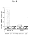
- FIG. 3 shows cavitation-erosion test results conducted by cavitation-erosion testing equipment whose schematic arrangement is shown in FIG. 4.
- 41 represents a magnetostrictive vibrator, 42 a transmitter, 43 a dial gauge, 44 a horn, 45 a test piece, 46 a test piece mount, 47 a test liquid tank, 48 a circulating pump and 49 a flow meter.
- the test piece 45 is set on the test piece mount 46 in a position just below a tip of the horn 44 mounted on the magnetostrictive vibrator 41.
- the horn 44 is vibrated with the high-frequency. Then, cavitation air bubbles are produced at the tip of the horn 44.
- a shock wave due to collaption of the cavitation air bubbles causes erosion of the surface of the test piece 45.
- a dynamic pressure journal bearing As a water lubricated bearing, a dynamic pressure journal bearing, a static pressure journal bearing, a dynamic pressure thrust bearing, a static pressure thrust bearing and the like are generally used. Any combination of the materials shown in Table 1 can be applied to a rotary member and a stationary member of these bearings. Moreover, in case of water lubricated seals, any combination of the materials shown in Table 1 can also be applied to a rotary member and a stationary member of the seals.
- FIG. 5 shows one arrangement of the water lubricated dynamic pressure journal bearing.
- FIG. 5(a) is a partially sectioned front view
- FIG. 5(b) is a partially sectioned side view.
- 51 represents a carrier ring
- 52 a pad stop
- 53 a pad
- 54 a joint pin
- 55 a stop pin
- 56 a joint bolt
- 57 a rotating shaft
- 58 a seal and 59 a seal retaining screw
- a combination of the materials shown in Table 1 may be used for sliding surfaces of the pad 53 (stationary member) and the rotating shaft 57 (rotary member). It is quite reasonable that the materials of the rotary member of the combination shown in Table 1 may be applied to the stationary member, and vice versa. As described above, the rotating shaft 57 and the pads 53 contact each other when starting and stopping the machine. Therefore, the combination of the materials shown in Table 1 may produce satisfactory results in terms of wear resistance. During rotation of the rotating shaft 57, the combination of the materials may produce the satisfactory results in terms of the cavitation-erosion resistance.
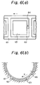
- FIG. 6 shows one arrangement of the water lubricated static pressure journal bearing.
- FIG. 6(a) is an unfolding view of a bearing surface
- FIG. 6(b) is a front view of the bearing.
- 61 represents a land, 62 a pocket, 63 a pad received in the pocket, 64 a hole for providing the lubricant (water) and concurrently serving as a throttle and 65 a rotating shaft.
- the bearing has a load ability due to a static pressure action of the lubricant and a dynamic pressure action of the pads 63 and the land 61 caused by rotating the rotating shaft 65.
- a combination of the materials shown in Table 1 may be used for sliding surfaces of the land 61 and the pads 63 (stationary member) and the rotating shaft 65 (rotary member).
- the materials of the rotary member of the combination shown in Table 1 may be applied to the stationary member, and vice versa.
- the combination of the materials shown in Table 1 may produce satisfactory results in terms of wear resistance.
- the combination of the materials may produce satisfactory results in terms of the cavitation-erosion resistance.
- FIG. 7 shows one arrangement of the water lubricated dynamic pressure thrust baring.
- FIG. 7(a) is a plan view and FIG. 7(b) is a cross-sectional view taken along the line A-A of FIG. 7(a).
- 71 represents a carrier ring, 72 a pad, 73 a pad stop, 74 an end pad stop, 75 an end pad stop retaining screw, 76 a stop key or pin, 77 an adjust spacer, 78 an adjust spacer retaining screw and 79 a shim.
- a rotary member (not shown) is rotated supportedly by a dynamic pressure produced between the rotary member and pad 82.
- a combination of the materials shown in Table 1 may be used for sliding surfaces of the rotary member and the pads 82 (stationary side member). It is quite reasonable that the materials of the rotary member of the combination shown in Table 1 may be applied to the stationary member, and vice versa. When starting and stopping a machine, the combination of the materials shown in Table 1 may produce satisfactory results in terms of wear resistance. Also during rotation of the rotating shaft 75, the combination of the materials may produce satisfactory results in terms of the cavitation-erosion resistance.
- FIG. 8 shows one arrangement of the water lubricated static pressure thrust bearing.
- FIG. 8(a) is a plan view
- FIG. 8(b) is a cross-sectional view taken along line B-B of FIG. 8(a).
- 81 represents a land, 82 a pocket, 83 a pad received in the pocket and 84 a hole for providing the lubricant (water) and concurrently serving as a throttle.
- the land 81 is at the same level with the pads 83.
- a rotary member (not shown) is rotated supportedly by a static pressure and a dynamic pressure produced between the rotary member and a bearing surface.
- a combination of the materials shown in Table 1 may be used for sliding surfaces of the rotary member and the pads 83 and the land 81 (stationary member). It is quite reasonable that the materials of the rotary member of the combination shown in Table 1 may be applied to the stationary member, and vice versa. When starting and stopping a machine, the combination of the materials shown in Table 1 may produce satisfactory results in terms of wear resistance. Also, during rotation of the rotating side member, the combination of the materials may produce satisfactory results in terms of the cavitation-erosion resistance.
- FIG. 9 shows one arrangement of a flat type water lubricated annular clearance seal.
- 91 represents a rotating shaft and 92 represents a liner ring.
- a narrow clearance formed between an outer surface of the rotating shaft 91 and an inner surface of the liner ring 92 reduces a leak from a high pressure side to a low pressure side.
- a combination of the materials shown in Table 1 may be used for sliding surfaces of the rotating shaft 91 (rotary member) and the liner ring 92 (stationary member). It is quite reasonable that the materials of the rotary member of the combination shown in Table 1 may be applied to the stationary member, and vice versa. When starting and stopping a machine, the combination of the materials shown in Table 1 may produce satisfactory results in terms of wear resistance. Also, during rotation of the rotating member, the combination of the materials may produce satisfactory results in terms of the cavitation-erosion resistance.
- FIG. 10 shows one arrangement of a typical screw type water lubricated seal and FIG. 11 shows one arrangement of a known double screw type water lubricated seal.
- 101 represents a rotating shaft and 102 represents a liner ring.
- a threaded groove 101a is formed on an outer periphery of the rotating shaft 101.
- threaded grooves 101a and 102a which are in an opposite direction each other (left-hand threaded groove 101a, right-hand threaded groove 102a), are formed on the outer periphery of the rotating shaft 101 and an inner periphery of the liner ring 102.
- Substrate materials of the rotary member or the stationary member for forming the thin TiN film thereon for constituting the water lubricated bearing or water lubricated seal are not limited to those shown in Table 1, and may be other metallic materials. Further, substrate materials for forming the thin DLC film, the thin CrN film and the like thereon are also not limited to those shown in Table 1, and may be other metallic materials. Film thicknesses of TiN, CrN, DLC and the like are not limited to those shown in Table 1.
- FIGS. 5 to 11 show some examples of arrangements of the dynamic pressure journal bearing, the static pressure journal bearing, the dynamic pressure thrust bearing, the static pressure thrust bearing and the seals.
- the water lubricated bearing or water lubricated seal of the present invention is not limited to these arrangements.
- the TiN film is formed on at least one sliding surface either one of the rotary member or the stationary member constituting the water lubricated bearing or water lubricated seal, and the nitride ceramic film, the oxide ceramic film, the carbide ceramic film, the hard chromium plating, or the zirconium boride film is formed on the other sliding surface.
- a martensitic stainless steel, a hard carbon, PEEK including a carbon fiber, or the PTFE including a carbon fiber is formed on the other sliding surface.
Abstract
Description
- The present invention relates to a water lubricated bearing or water lubricated seal which has high wear resistance and a low coefficient of friction, and more particularly to a water lubricated bearing or water lubricated seal which is suitable for use in fluid machinery, e.g., pumps, turbines, compressors, etc.
- Many conventional water lubricated bearings or water lubricated seals which have heretofore been used for fluid machinery, e.g., pumps, turbines, compressors, etc., have an arrangement comprising a combination of a movable member which employs a ceramic material such as SiC as a substrate, and a stationary member which employs a hard metal such as tungsten carbide (WC) as a substrate.
- With the need for fluid machinery to be reduced in size, operate at higher speed and increase in capacity, service conditions under which seals and bearings are used have become increasingly adverse in recent years. That is, seals and bearings are now used under high-speed and heavy-load conditions. Accordingly, it has been pointed out that a material such as a hard metal which has heretofore been used for seals and bearings gives rise to problems such as fracturing under thermal shock and thermal fatigue cracking, caused by repeated application of friction heat generated by sliding contact between solids.
- On the other hand, ceramic materials, e.g., SiC, are superior to hard metals in resistance to thermal stress caused by sliding. However, when used as a material for a high-speed rotating member, a ceramic material is inferior in mechanical strength and lacks resistance to shock. Further, when a metallic material is used as a sliding member, the surface of the metallic material may be subjected to carburizing, nitrating or other similar hardening treatment. With these surface treatments, however, a satisfactory sliding surface cannot be obtained in terms of the hardness of the modified layer itself and the deformation of the substrate after the treatment.
- In addition, in a conventional water lubricated bearing or water lubricated seal adopting a titanium nitride film coated on a substrate of a metallic material, since an appropriate material for mating with the titanium nitride film has not been provided, sufficient sliding characteristics in water could not been obtained.
- In view of the above-described circumstances, an object of the present invention is to provide a water lubricated bearing or water lubricated seal which has a reduced coefficient of friction, and which provides improved wear resistance.
- Another object of the present invention is to provide a water lubricated bearing or water lubricated seal which has excellent anti-heat shock and anti-mechanical shock properties.
- To solve the above-described problems, according to a first aspect of the present invention, a water lubricated bearing or water lubricated seal using water as a lubricant comprises: a rotary member secured directly or indirectly to a rotary side, and a stationary member secured directly or indirectly to a stationary side and facing the rotary member for making sliding contact therewith; wherein a substrate of either one of the rotary member and the stationary member is a metallic material and a thin titanium nitride film is formed on sliding surface thereof, and wherein the other member is made of a non-brittle material or a film of hard material is formed on the sliding surface thereof.
- The non-brittle material may be a metallic material, and the film of hard material may be a ceramic film.
- The ceramic film may be a nitride ceramic film such as a chromium nitride film, a boron nitride film, a titanium nitride film, or a film made of a material consisting essentially of an iron nitride, an oxide ceramic film such as a film made of a material consisting essentially of a chromium oxide, an aluminium oxide, a titanium oxide, a zirconium oxide, or a composite oxide of an aluminium oxide and a chromium oxide, or a carbide ceramic film such as a diamond-like carbon film, or a film made of a material consisting essentially of a tungsten carbide or a chromium carbide.
- In a water lubricated bearing or water lubricated seal described above, the ceramic film may be formed by chemical vapor deposition, physical vapor deposition, spraying, wet plating or hot dipping.
- The physical vapor deposition may be effected by a film forming method using an ion beam such as sputtering, ion plating, ion implantation, a joint method of ion implantation and vacuum evaporation, or the like.
- According to a second aspect of the present invention, in a water lubricated bearing or water lubricated seal according to the first aspect, the non-brittle material is a metallic material, and the film of hard material is a hard chromium plating formed on the sliding surface of the other member.
- According to a third aspect of the present invention, in a water lubricated bearing or water lubricated seal according to the first aspect: at least the sliding surface of the other member is made of a martensitic stainless steel.
- According to a fourth aspect of the present invention, in a water lubricated bearing or water lubricated seal according to the first aspect: at least the sliding surface of the other member is made of a polyether ether ketone including a carbon fiber or a polytetrafluoroethylen resin including a carbon fiber.
- According to a fifth aspect of the present invention, a water lubricated bearing or water lubricated seal using water as a lubricant comprises: a rotary member secured directly or indirectly to a rotary side, and a stationary member secured directly or indirectly to a stationary side and facing the rotary member for making sliding contact therewith; wherein a substrate of either one of the rotary member and the stationary member is a metallic material and a thin titanium nitride film is formed on the sliding surface thereof, wherein at least the sliding surface of the other member is made of a hard carbon.
- According to the arrangement of the present invention described above, since the substrate of the rotary member and the stationary member or the rotary member and the stationary member themselves are made of a non-brittle material, they can provide excellent anti-heat shock and anti-mechanical shock properties. In addition, since the sliding surface of the rotary member and or the stationary member is formed with a film of hard material, it can provide a low coefficient of friction and improved wear resistance.
- The above and other objects, features and advantages of the present invention will become more apparent from the following description when taken in conjunction with the accompanying drawings in which preferred embodiments of the present invention are shown by way of illustrative examples.
- FIG. 1 is a conceptual view showing the arrangement for forming a thin titanium nitride film on a substrate by a dynamic ion mixing method;
- FIG. 2 is a view showing a schematic arrangement of a frictional wear testing machine;
- FIG. 3 shows the results of comparison as to the cavitation-erosion test;
- FIG. 4 schematically shows arrangement of a cavitation-erosion testing equipment;
- FIG. 5 shows one arrangement of a water lubricated dynamic pressure journal bearing, wherein FIG. 5(a) is a front view, and FIG. 5(b) is a side view, with a portion in section,
- FIG. 6 shows one arrangement of a water lubricated static pressure journal bearing, wherein FIG. 6(a) is an unfolding view of a bearing surface, and FIG. 6(b) is a front view of the bearing;
- FIG. 7 shows one arrangement of a water lubricated dynamic pressure thrust bearing, wherein FIG. 7(a) is a plan view of the bearing and FIG. 7(b) is a cross-sectional view taken along line A-A of FIG. 7(a);
- FIG. 8 shows one arrangement of a water lubricated static pressure thrust bearing, wherein FIG. 8(a) is a plan view of the bearing and FIG. 8(b) is a cross-sectional view taken along line B-B of FIG. 8(a);
- FIG. 9 is a cross-sectional view showing one arrangement of a water lubricated seal;
- FIG. 10 is a cross-sectional view showing one arrangement of a screw type water lubricated seal; and
- FIG. 11 is a cross-sectional view showing one arrangement of a double screw type water lubricated seal.
- Preferred embodiments of the present invention will now be described. The water lubricated bearing or water lubricated seal of the invention is composed of a rotary member secured directly or indirectly to a rotary side and a stationary member secured directly or indirectly to a stationary side and facing the rotary member for making sliding contact therewith. In the embodiments of the present invention, the water lubricated bearings or water lubricated seals were composed of the rotary members and the stationary members with a combination of the materials shown in Table 1. Table 2 shows frictional wear test results using a combination of the materials shown in Table 1 under the test conditions shown in Table 3.
Table 1 Rotary side member Stationary side member Substrate Sliding Surface Film thickness (µm) Substrate Sliding surface Film thickness (µm) Vickers Hardness HV Comparative Example 1 SUS420J2 SUS420J2 400 - 500 Comparative Example 2 SUS630 SUS630 400 - 500 Example 1 * TiN 3 SUS420J2 400 - 500 Example 2 * TiN 3 SUS630 400 - 500 Example 3 * TiN 3 * CrN 4 1500 or more Example 4 * TiN 3 * DLC 1 2500 or more Example 5 * TiN 3 * BN 1 2000 or more Example 6 * TiN 3 * Hard Cr plating 100-150 600 - 800 Example 7 * TiN 3 *** Nitride 50 800 - 1000 Example 8 * TiN 3 ** W2C+Ti*1 1000 800 - 1200 Example 9 * TiN 3 * WC+Ni+P*2 400 800 - 1200 Example 10 * TiN 10 ** W2C+Ti*1 1000 800 - 1200 Example 11 * TiN 10 * WC+Ni+P*2 400 800 - 1200 Example 12 * TiN 10 * WC+NiCr*3 100 800 - 1200 Example 13 * TiN 10 * Cr3C2+NiCr*4 200 800 - 1200 Example 14 * TiN 3 * Al2O3 200 800 - 1200 Example 15 * TiN 3 * Al2O3+2.5TiO2+2SiO2 200 800 - 1200 Example 16 * TiN 3 * ZrO2+5CaO+4SiO2 200 800 - 1200 Example 17 * TiN 3 * Cr2O3 200 800 - 1200 Example 18 * TiN 3 * TiN 200 2500 or more Example 19 * TiN 3 Hard carbon 800 - 1200 Example 20 * TiN 3 PTFE+CF Example 21 * TiN 3 PEEK+CF * : SUS2316L ** : SUS304 *** : SUS630 **** : SUS410 *1 : plasma transferred arc spraying build up method (PTA) *2 : plasma spraying method (PS) *3 : plasma jet spraying method (PJS) *4 : vacuum plasma spraying method (VPS) -
Table 2 Seizure surface pressure (Mpa) Coefficient of friction Observed result of the sliding surface after the test Damage at rotary side Damage at Stationary side Comparative Example 1 0.1 Pronounced Pronounced Comparative Example 2 0.1 Pronounced Pronounced Example 1 0.4 0.2 Slight Slight Example 2 0.4 0.2 Slight Slight Example 3 0.6 0.1 None None Example 4 0.8 0.1 None None Example 5 0.7 0.1 None None Example 6 0.4 0.1 - 0.3 None None Example 7 0.3 0.1 None None Example 8 0.1 Slight Slight Example 9 0.1 Slight Slight Example 10 0.2 0.3 Slight Slight Example 11 0.3 0.1 Slight Slight Example 12 0.2 0.2 Slight Slight Example 13 0.3 0.2 Slight Slight Example 14 0.4 0.1 Slight Slight Example 15 0.3 0.1 Slight Slight Example 16 0.2 0.2 Slight Slight Example 17 0.4 0.1 Slight Slight Example 18 0.2 0.2 Slight Slight Example 19 1.0 or more 0.1 None Slight Example 20 1.0 or more 0.1 None Slight Example 21 1.0 or more 0.2 Slight Slight - In Examples 1 to 7 shown in Table 1, the stainless steel (SUS316L) was used for a substrate of each rotary member, and a thin TiN film of 3 µm in thickness was formed on a sliding surface thereof. The stainless steel (SUS316L, SUS420J2 or SUS630) was used for a substrate of the stationary member in Examples 3 to 7, and a non-processed sliding surface thereof made of the SUS420J2 steel and SUS630 steel were used in Examples 1 and 2, respectively. A thin CrN film of 4 µm in thickness was formed on the sliding surface in Example 3. A thin DLC (diamond-like carbon) film of 1 µm in thickness was formed in Example 4. A thin BN film of 1 µm in thickness was formed in Example 5. A hard Cr plating of 100 to 150 µm in thickness was formed in Example 6. A thin nitride film of 50 µm in thickness was used in Example 7.
- In Examples 8 and 9, the SUS316L was used for the substrate of the rotary member, and the thin TiN film of 3 µm in thickness was formed on the sliding surface thereof. In Example 8, the SUS304 was used for the substrate of the stationary member, and a thin W2C+Ti film of 1000 µm in thickness was formed on the sliding surface thereof by a plasma transferred arc spraying build up method (PTA). In Example 9, the SUS316L was used for the substrate of the stationary member, and a WC+Ni+P film of 400 µm in thickness was formed by a plasma spraying method.
- In Examples 10 to 13, the SUS316L was used for the substrate of the rotary member, and the thin TiN film of 10 µm in thickness was formed on the sliding surface thereof. In Example 10, the SUS304 was used for the substrate of the stationary member, and the W2C+Ti film of 1000 µm in thickness was formed on the sliding surface thereof by a plasma transferred arc spraying build up method (PTA). In Example 11, the SUS316L was used for the substrate of the stationary member, and the WC+Ni+P film of 400 µm in thickness was formed on the sliding surface thereof by the plasma spraying method. In Example 12, the SUS316L was used for the substrate of the stationary member, and a WC+NiCr film of 100 µm in thickness was formed on the sliding surface thereof by a plasma jet spraying method. In Example 13, the SUS316L was used for the substrate of the stationary member, and a Cr3C2+NiCr film of 200 µm in thickness was formed on the sliding surface thereof by a vacuum plasma spraying method.
- In Examples 14 to 18, the SUS316L was used for the substrate of the rotary member, and the thin TiN film of 3 µm in thickness was formed on the sliding surface thereof. In Example 14, the SUS316L was used for the substrate of the stationary member, and the Al2O3 film of 200 µm in thickness was formed on the sliding surface thereof by a plasma spraying method. In Example 15, the SUS316L was used for the substrate of the stationary member, and Al2O3+2.5TiO2+2SiO2 film of 200 µm in thickness was formed on the sliding surface thereof by a plasma spraying method. In Example 16, the SUS316L was used for the substrate of the stationary member, and the ZrO3 +5CaO+0.4SiO2 film of 200 µm in thickness was formed on the sliding surface thereof by a plasma spraying method. In Example 17, the SUS316L was used for the substrate of the stationary member, and the Cr2O3 film of 200 µm in thickness was formed on the sliding surface thereof by a plasma spraying method. In Example 18, the SUS316L was used for the substrate of the stationary member, and the TiN film of 200 µm in thickness was formed on the sliding surface thereof by a plasma spraying method.
- In Examples 19 to 21, the SUS316L was used on the substrate of the rotary member, and the thin TiN film of 3µm in thickness was formed on the sliding surface thereof. A hard carbon was used for the material of the stationary member in Example 19, the PTFE (polytetrafluoroethylen) resin including a carbon fiber was used for the material of the stationary member in Example 20, and PEEK (polyethyl ethyl ketone) including a carbon fiber was used for the material of the stationary member in Example 21.
Table 3 Conditions for a Frictional Wear Test Surface pressure 0.1 MPa or more (step up per 0.1MPa) Peripheral speed 0.5 m/s Traveling distance 1000 m (for each surface pressure) Test temperature Room temperature Lubricant Distilled water - A surface pressure is a pressure that is applied between the sliding surface of a
rotary member 10 and the sliding surface of astationary member 13 in FIG. 2, a peripheral speed represents a sliding speed of therotary member 10, a traveling distance represents a sliding distance between therotary member 10 and thestationary member 13. - FIG. 2 shows a schematic arrangement of a frictional wear testing machine. The frictional wear test was conducted by securing the
rotary member 10 formed with athin TiN film 12 on a sliding surface of asubstrate 11 to a distal end of arotating shaft 16, by disposing thestationary member 13 formed with or not formed with athin film 15 on a sliding surface of asubstrate 14 so as to contact therotary member 10, and by rotating therotating shaft 16 while applying a predetermined pressure (load) thereto. Starting at 0.1 MPa of a surface pressure, the pressure was increased in increments of 0.1 MPa until a torque is rapidly increased or a torque fluctuation is acute, which point was defined as a critical surface pressure or seizure surface pressure. - As apparent from Table 2, seizure surface pressures of Examples 1 to 7 were higher than those of Comparative Examples of the prior art, no damage was observed to either of the sliding surfaces of the rotary members or the stationary members below the seizure surface pressures thereof in Examples 3 to 7, and only a slight amount of damage was observed on the sliding surface of the rotary member and the stationary member in Examples 1 and 2. Examples 1 to 7 showed excellent results compared with Comparative Examples 1 to 3. In Examples 8 to 13, the seizure surface pressures were equal to or higher than those of Comparative Examples, and only a slight amount of damage was observed on the sliding surfaces of the rotary member and the stationary member. In Examples 14 to 21, the seizure surface pressure was higher than those of Comparative Examples, and only a slight amount of damage or no damage was observed on the sliding surfaces of the rotary side member and the stationary side member.
- Specific values of the film thickness shown in Table 1 are just examples and are not limited thereto. For example, in Examples 1 to 5 shown in Table 1, a film thickness of the titanium nitride (TiN) on the sliding surface of the rotary member is 3 µm, a film thickness of the DLC and BN on the sliding surface of the stationary side member is 1 µm, and a film thickness of the CrN was 4 µm. However, the film thickness of these films may be some µm to some hundreds µm.
- For forming the thin TiN film on the sliding surface of the rotary member or the stationary member mentioned above, so called a dynamic ion mixing method described below was used. FIG. 1 is a conceptual view for forming the TiN film by the dynamic ion mixing method. As shown in FIG. 1, the thin TiN film was formed on a surface of a
substrate 2 by securing thesubstrate 2 on a copper holder 1 which is in turn secured at a distal end of arotating shaft 5 and water-cooled, disposing anevaporation source 3 and anion source 4 facing thesubstrate 2, emitting titanium vapor 7 from theevaporation source 3 toward thesubstrate 2, and irradiating thesubstrate 2 with anitrogen ion beam 6 consisting essentially of nitrogen ions emitted from theion source 4. It is confirmed experimentally that the thin TiN film formed by the dynamic ion mixing method has stronger adhesion force to thesubstrate 2 and a remarkably smaller specific wear rate compared with that formed by other methods. - Also, when a titanium nitride film is formed by a dynamic ion mixing method, since a surface roughness does not appreciably change under film formation and there is no substantial deformation of a substrate by such film formation, it is not necessary to effect machining or lapping the surface after film formation.
- The thin titanium nitride (TiN) film has excellent wear resistance as described above, and has excellent cavitation-erosion resistance as well. FIG. 3 shows cavitation-erosion test results conducted by cavitation-erosion testing equipment whose schematic arrangement is shown in FIG. 4. In FIG. 4, 41 represents a magnetostrictive vibrator, 42 a transmitter, 43 a dial gauge, 44 a horn, 45 a test piece, 46 a test piece mount, 47 a test liquid tank, 48 a circulating pump and 49 a flow meter. The
test piece 45 is set on the test piece mount 46 in a position just below a tip of thehorn 44 mounted on themagnetostrictive vibrator 41. Thehorn 44 is vibrated with the high-frequency. Then, cavitation air bubbles are produced at the tip of thehorn 44. A shock wave due to collaption of the cavitation air bubbles causes erosion of the surface of thetest piece 45. - As shown in FIG. 3, 70 µm or more average damage depth was produced on a non-processed surface made of the SUS420J2 steel. On the other hand, only damage of about 1 µm depth was produced on a surface coated with the thin TiN film. In addition, damage of about 10 µm average damage depth was produced on a non-processed surface made of the SUS304 steel. On the other hand, only damage of about 1 µm depth was produced on a surface coated with the thin TiN film. In other words, it was found that coating the surface with the thin TiN film improved remarkably the cavitation-erosion resistance.
- As a water lubricated bearing, a dynamic pressure journal bearing, a static pressure journal bearing, a dynamic pressure thrust bearing, a static pressure thrust bearing and the like are generally used. Any combination of the materials shown in Table 1 can be applied to a rotary member and a stationary member of these bearings. Moreover, in case of water lubricated seals, any combination of the materials shown in Table 1 can also be applied to a rotary member and a stationary member of the seals.
- FIG. 5 shows one arrangement of the water lubricated dynamic pressure journal bearing. FIG. 5(a) is a partially sectioned front view, and FIG. 5(b) is a partially sectioned side view. In FIG. 5, 51 represents a carrier ring, 52 a pad stop, 53 a pad, 54 a joint pin, 55 a stop pin, 56 a joint bolt, 57 a rotating shaft, 58 a seal and 59 a seal retaining screw. When starting and stopping a machine, the rotating
shaft 57 and thepads 53 contact each other. Once the rotatingshaft 57 is rotated, a dynamic pressure by a lubricant (water) is produced between therotating shaft 57 and thepads 53, androtating shaft 57 is supported by thepads 53 without contact. A combination of the materials shown in Table 1 may be used for sliding surfaces of the pad 53 (stationary member) and the rotating shaft 57 (rotary member). It is quite reasonable that the materials of the rotary member of the combination shown in Table 1 may be applied to the stationary member, and vice versa. As described above, the rotatingshaft 57 and thepads 53 contact each other when starting and stopping the machine. Therefore, the combination of the materials shown in Table 1 may produce satisfactory results in terms of wear resistance. During rotation of therotating shaft 57, the combination of the materials may produce the satisfactory results in terms of the cavitation-erosion resistance. - FIG. 6 shows one arrangement of the water lubricated static pressure journal bearing. FIG. 6(a) is an unfolding view of a bearing surface, and FIG. 6(b) is a front view of the bearing. In FIG. 6, 61 represents a land, 62 a pocket, 63 a pad received in the pocket, 64 a hole for providing the lubricant (water) and concurrently serving as a throttle and 65 a rotating shaft. The bearing has a load ability due to a static pressure action of the lubricant and a dynamic pressure action of the
pads 63 and theland 61 caused by rotating therotating shaft 65. A combination of the materials shown in Table 1 may be used for sliding surfaces of theland 61 and the pads 63 (stationary member) and the rotating shaft 65 (rotary member). It is quite reasonable that the materials of the rotary member of the combination shown in Table 1 may be applied to the stationary member, and vice versa. When starting and stopping a machine, the combination of the materials shown in Table 1 may produce satisfactory results in terms of wear resistance. Also, during rotation of therotating shaft 65, the combination of the materials may produce satisfactory results in terms of the cavitation-erosion resistance. - FIG. 7 shows one arrangement of the water lubricated dynamic pressure thrust baring. FIG. 7(a) is a plan view and FIG. 7(b) is a cross-sectional view taken along the line A-A of FIG. 7(a). In FIG. 7, 71 represents a carrier ring, 72 a pad, 73 a pad stop, 74 an end pad stop, 75 an end pad stop retaining screw, 76 a stop key or pin, 77 an adjust spacer, 78 an adjust spacer retaining screw and 79 a shim. A rotary member (not shown) is rotated supportedly by a dynamic pressure produced between the rotary member and
pad 82. A combination of the materials shown in Table 1 may be used for sliding surfaces of the rotary member and the pads 82 (stationary side member). It is quite reasonable that the materials of the rotary member of the combination shown in Table 1 may be applied to the stationary member, and vice versa. When starting and stopping a machine, the combination of the materials shown in Table 1 may produce satisfactory results in terms of wear resistance. Also during rotation of therotating shaft 75, the combination of the materials may produce satisfactory results in terms of the cavitation-erosion resistance. - FIG. 8 shows one arrangement of the water lubricated static pressure thrust bearing. FIG. 8(a) is a plan view, and FIG. 8(b) is a cross-sectional view taken along line B-B of FIG. 8(a). In FIG. 8, 81 represents a land, 82 a pocket, 83 a pad received in the pocket and 84 a hole for providing the lubricant (water) and concurrently serving as a throttle. The
land 81 is at the same level with thepads 83. A rotary member (not shown) is rotated supportedly by a static pressure and a dynamic pressure produced between the rotary member and a bearing surface. A combination of the materials shown in Table 1 may be used for sliding surfaces of the rotary member and thepads 83 and the land 81 (stationary member). It is quite reasonable that the materials of the rotary member of the combination shown in Table 1 may be applied to the stationary member, and vice versa. When starting and stopping a machine, the combination of the materials shown in Table 1 may produce satisfactory results in terms of wear resistance. Also, during rotation of the rotating side member, the combination of the materials may produce satisfactory results in terms of the cavitation-erosion resistance. - FIG. 9 shows one arrangement of a flat type water lubricated annular clearance seal. In FIG. 9, 91 represents a rotating shaft and 92 represents a liner ring. A narrow clearance formed between an outer surface of the
rotating shaft 91 and an inner surface of theliner ring 92 reduces a leak from a high pressure side to a low pressure side. A combination of the materials shown in Table 1 may be used for sliding surfaces of the rotating shaft 91 (rotary member) and the liner ring 92 (stationary member). It is quite reasonable that the materials of the rotary member of the combination shown in Table 1 may be applied to the stationary member, and vice versa. When starting and stopping a machine, the combination of the materials shown in Table 1 may produce satisfactory results in terms of wear resistance. Also, during rotation of the rotating member, the combination of the materials may produce satisfactory results in terms of the cavitation-erosion resistance. - FIG. 10 shows one arrangement of a typical screw type water lubricated seal and FIG. 11 shows one arrangement of a known double screw type water lubricated seal. In FIGS. 10 and 11, 101 represents a rotating shaft and 102 represents a liner ring. In FIG. 10, a threaded
groove 101a is formed on an outer periphery of therotating shaft 101. In FIG. 11, threadedgrooves groove 101a, right-hand threadedgroove 102a), are formed on the outer periphery of therotating shaft 101 and an inner periphery of theliner ring 102. By rotating therotating shaft 101, sealing action is effected due to a pumping action of the threaded groove formed on the rotating shaft 101 (FIG. 10) or threaded grooves formed on therotating shaft 101 and on the liner ring 102 (FIG. 11), producing a flow from a low pressure side to a high pressure side. A combination of the materials shown in Table 1 may be used for sliding surfaces of the rotating shaft 101 (rotary member) and the liner ring 102 (stationary member). It is quite reasonable that the materials of the rotary member of the combination shown in Table 1 may be applied to the stationary member and vice versa. When starting and stopping a machine, the combination of the materials shown in Table 1 may produce satisfactory results in terms of wear resistance. During rotation of the rotating member, the combination of the materials may produce satisfactory results regarding the cavitation-erosion resistance. - Substrate materials of the rotary member or the stationary member for forming the thin TiN film thereon for constituting the water lubricated bearing or water lubricated seal are not limited to those shown in Table 1, and may be other metallic materials. Further, substrate materials for forming the thin DLC film, the thin CrN film and the like thereon are also not limited to those shown in Table 1, and may be other metallic materials. Film thicknesses of TiN, CrN, DLC and the like are not limited to those shown in Table 1.
- FIGS. 5 to 11 show some examples of arrangements of the dynamic pressure journal bearing, the static pressure journal bearing, the dynamic pressure thrust bearing, the static pressure thrust bearing and the seals. The water lubricated bearing or water lubricated seal of the present invention is not limited to these arrangements.
- As has been described above, the present invention provides the following advantageous effect. The TiN film is formed on at least one sliding surface either one of the rotary member or the stationary member constituting the water lubricated bearing or water lubricated seal, and the nitride ceramic film, the oxide ceramic film, the carbide ceramic film, the hard chromium plating, or the zirconium boride film is formed on the other sliding surface. Instead, a martensitic stainless steel, a hard carbon, PEEK including a carbon fiber, or the PTFE including a carbon fiber is formed on the other sliding surface. Thereby, the water lubricated bearing or water lubricated seal having a low coefficient of friction, and excellent water resistance and cavitation-erosion resistance can be provided.
Claims (14)
- A water lubricated bearing or water lubricated seal using water as a lubricant comprising :a rotary member secured directly or indirectly to a rotary side, anda stationary member secured directly or indirectly to a stationary side and facing said rotary member for making sliding contact therewith;
wherein a substrate of either one of said rotary member and said stationary member is a metallic material and a thin titanium nitride film is formed on sliding surface thereof, and wherein the other member is made of a non-brittle material or a film of hard material is formed on the other sliding surface thereof. - A water lubricated bearing or water lubricated seal claimed in Claim 1, wherein said non-brittle material is a metallic material, and said film of hard material is a ceramic film.
- A water lubricated bearing or water lubricated seal claimed in Claim 2, wherein said ceramic film is a nitride ceramic film.
- A water lubricated bearing or water lubricated seal claimed in Claim 3, wherein said nitride ceramic film is a chromium nitride film, a boron nitride film, a titanium nitride film or a film made of a material consisting essentially of an iron nitride.
- A water lubricated bearing or water lubricated seal claimed in Claim 2, wherein said ceramic film is an oxide ceramic film.
- A water lubricated bearing or water lubricated seal claimed in Claim 5, wherein said oxide ceramic film is a film made of a material consisting essentially of a chromium oxide, an aluminium oxide, a titanium oxide, a zirconium oxide, or a composite oxide of an aluminium oxide and a chromium oxide.
- A water lubricated bearing or water lubricated seal claimed in Claim 2, wherein said ceramic film is a carbide ceramic film.
- A water lubricated bearing or water lubricated seal claimed in Claim 7, wherein said carbide ceramic film is a diamond-like carbon film, or a film made of a material consisting essentially of a tungsten carbide or a chromium carbide.
- A water lubricated bearing or water lubricated seal claimed in any one of Claims 1 to 8, wherein said ceramic film is formed by chemical vapor deposition, physical vapor deposition, spraying, wet plating or hot dipping.
- A water lubricated bearing or water lubricated seal claimed in Claim 9, wherein said physical vapor deposition is effected by a film forming method using an ion beam such as sputtering, ion plating, ion implantation, a joint method of ion implantation and vacuum evaporation, or the like.
- A water lubricated bearing or water lubricated seal claimed in Claim 1, wherein said non-brittle material is metallic material, and wherein said film of hard material is hard chromium plating formed on the sliding surface of said the other member.
- A water lubricated bearing or water lubricated seal claimed in Claim 1, wherein at least the sliding surface of the other member is made of a martensitic stainless steel.
- A water lubricated bearing or water lubricated seal claimed in Claim 1, wherein at least the sliding surface of the other member is made of a polyether ether ketone including a carbon fiber or a polytetrafluoroethylen resin including a carbon fiber.
- A water lubricated bearing or water lubricated seal using water as a lubricant comprising:a rotary member secured directly or indirectly to a rotary side, anda stationary member secured directly or indirectly to a stationary side and facing said rotary member for making sliding contact therewith;
wherein a substrate of either one of said rotary member and said stationary member is a metallic material and a thin titanium nitride film is formed on the sliding surface thereof, wherein at least the sliding surface of the other member is made of a hard carbon.
Applications Claiming Priority (4)
| Application Number | Priority Date | Filing Date | Title |
|---|---|---|---|
| JP5832396 | 1996-02-20 | ||
| JP58323/96 | 1996-02-20 | ||
| JP313034/96 | 1996-11-07 | ||
| JP31303496 | 1996-11-07 |
Publications (2)
| Publication Number | Publication Date |
|---|---|
| EP0791760A2 true EP0791760A2 (en) | 1997-08-27 |
| EP0791760A3 EP0791760A3 (en) | 1997-09-10 |
Family
ID=26399377
Family Applications (1)
| Application Number | Title | Priority Date | Filing Date |
|---|---|---|---|
| EP97102688A Withdrawn EP0791760A3 (en) | 1996-02-20 | 1997-02-19 | Water lubricated bearing or water lubricated seal |
Country Status (4)
| Country | Link |
|---|---|
| US (2) | US5961218A (en) |
| EP (1) | EP0791760A3 (en) |
| JP (1) | JP3963994B2 (en) |
| CN (1) | CN1077661C (en) |
Cited By (5)
| Publication number | Priority date | Publication date | Assignee | Title |
|---|---|---|---|---|
| WO2000008343A1 (en) * | 1998-08-03 | 2000-02-17 | Ksb Aktiengesellschaft | Water-lubricated shaft bearing |
| EP1229269A1 (en) * | 1999-11-10 | 2002-08-07 | Ebara Corporation | Power transmission device |
| WO2008143589A1 (en) * | 2007-05-21 | 2008-11-27 | Panasonic Corporation | Refrigerant compressor sliding surface with non-integral reaction layer |
| WO2013020880A1 (en) * | 2011-08-09 | 2013-02-14 | Schaeffler Technologies AG & Co. KG | Medium-lubricated bearing arrangement for use in a corrosive medium, more particularly sea water |
| EP3630387A4 (en) * | 2017-06-03 | 2021-01-06 | Saradva, Atulkumar Raghavjibhai | A process of manufacturing of segments for carbon thrust bearing |
Families Citing this family (36)
| Publication number | Priority date | Publication date | Assignee | Title |
|---|---|---|---|---|
| JP2001074041A (en) * | 1999-09-06 | 2001-03-23 | Enplas Corp | Sliding bearing and rotational sliding body |
| EP1227254A1 (en) * | 2001-01-24 | 2002-07-31 | ALSTOM (Switzerland) Ltd | Thrust bearing for a generator |
| DE10345827A1 (en) * | 2003-10-02 | 2005-05-04 | Daimler Chrysler Ag | Process for coating metallic substrates with oxidizing materials by means of arc wire spraying |
| US20050255329A1 (en) * | 2004-05-12 | 2005-11-17 | General Electric Company | Superalloy article having corrosion resistant coating thereon |
| DE102004033321B4 (en) * | 2004-07-09 | 2006-03-30 | Brueninghaus Hydromatik Gmbh | Axial piston machine with wear protection layer |
| JP2006138404A (en) * | 2004-11-12 | 2006-06-01 | Kobe Steel Ltd | Sliding member with excellent abrasion resistance in wet environment |
| CN100383423C (en) * | 2004-11-19 | 2008-04-23 | 鸿富锦精密工业(深圳)有限公司 | Bearing system |
| CN100344891C (en) * | 2004-12-23 | 2007-10-24 | 大连三环复合材料技术开发有限公司 | Water labricating metal plastic bush and producing method |
| EP1748109A1 (en) | 2005-07-25 | 2007-01-31 | Nederlandse Organisatie voor Toegepast-Natuuurwetenschappelijk Onderzoek TNO | Pile driver |
| US20090092796A1 (en) * | 2006-02-06 | 2009-04-09 | Yoshinori Ishida | Sliding member and method for manufacturing the same |
| JP2008163430A (en) | 2006-12-28 | 2008-07-17 | Jtekt Corp | High corrosion-resistant member and its manufacturing method |
| JP2008202642A (en) * | 2007-02-16 | 2008-09-04 | Matsushita Electric Ind Co Ltd | Fluid bearing device, spindle motor with it, recording and reproducing device and manufacturing method of bearing component |
| JP4764486B2 (en) * | 2009-02-27 | 2011-09-07 | 三菱重工業株式会社 | Journal bearing |
| JP2011026398A (en) * | 2009-07-23 | 2011-02-10 | Yamatake Corp | Sliding structure |
| US8602753B2 (en) | 2009-09-21 | 2013-12-10 | Flowserve Management Company | Radial bearings for deep well submersible pumps |
| CN102059127B (en) * | 2010-11-09 | 2012-11-21 | 华东理工大学 | Catalyst for CO normal temperature catalytic oxidation and preparation method thereof |
| CN102758182A (en) * | 2011-04-27 | 2012-10-31 | 鸿富锦精密工业(深圳)有限公司 | Iron-based alloy surface coating method and coated piece produced by same |
| ES2543579T3 (en) * | 2012-02-15 | 2015-08-20 | Ihi Hauzer Techno Coating B.V. | Bearing components and bearings isolated against current |
| JP5851880B2 (en) * | 2012-02-24 | 2016-02-03 | 三菱重工業株式会社 | Bearing device |
| DE102012207661A1 (en) * | 2012-05-08 | 2013-11-14 | Bayerische Motoren Werke Aktiengesellschaft | Water-lubricated shaft assembly for high pressure radial flow fan, has bearing arrangements for bearing of fan shaft, where bearing elements of one of arrangements, and rings and elements of other arrangement are coated with carbon coating |
| CN102748380B (en) * | 2012-07-06 | 2015-04-15 | 东南大学 | High-speed water bearing structure with micro-arc oxidation film layer |
| DE102012218619A1 (en) * | 2012-10-12 | 2014-04-17 | Schaeffler Technologies Gmbh & Co. Kg | Media lubricated bearing |
| CN104632893A (en) * | 2014-12-25 | 2015-05-20 | 江南大学 | Porous hydrostatic pressure bearing structure based on hydrophobic interfaces |
| CN104533955B (en) * | 2015-01-13 | 2017-01-25 | 江南大学 | Water lubrication tilting pad static-pressure bearing structure cooled through water returning grooves |
| TW201627584A (en) | 2015-01-17 | 2016-08-01 | 伊格爾工業股份有限公司 | Water-lubricated bearing material |
| CN105889327A (en) * | 2015-01-26 | 2016-08-24 | 株洲时代新材料科技股份有限公司 | Composite bearing bush strip |
| CN106763147A (en) * | 2017-01-09 | 2017-05-31 | 重庆大学 | NEW ADAPTIVE water lubricating thrust bearing |
| CN109385153B (en) * | 2018-10-29 | 2021-05-25 | 山东建筑大学 | Irradiation-resistant space solid lubricating coating and preparation method thereof |
| CN109899393A (en) * | 2019-03-20 | 2019-06-18 | 武汉理工大学 | A kind of water lubrication tail bearing with lath detachable structure |
| DE102019125839A1 (en) * | 2019-09-25 | 2021-04-08 | Danfoss A/S | Method of manufacturing a water hydraulic machine |
| CN111038050B (en) * | 2019-12-03 | 2021-11-05 | 合肥一密科技有限公司 | Self-lubricating and high-wear-resistance non-metal sealing sliding block and manufacturing method thereof |
| GB202005022D0 (en) * | 2020-04-06 | 2020-05-20 | Rolls Royce Plc | Gearboxes for aircraft gas turbine engines |
| GB202005025D0 (en) | 2020-04-06 | 2020-05-20 | Rolls Royce Plc | Gearboxes for aircraft gas turbine engines |
| GB202005028D0 (en) | 2020-04-06 | 2020-05-20 | Rolls Royce Plc | Gearboxes for aircraft gas turbine engines |
| GB202005033D0 (en) | 2020-04-06 | 2020-05-20 | Rolls Royce Plc | Gearboxes for aircraft gas turbine engines |
| CN111927875B (en) * | 2020-08-18 | 2021-10-12 | 南昌工程学院 | Machining method of corrosion-resistant water pump thrust bearing with composite bearing bush |
Citations (9)
| Publication number | Priority date | Publication date | Assignee | Title |
|---|---|---|---|---|
| DE3435821A1 (en) * | 1983-09-30 | 1985-05-02 | Ebara Corp | COMBINATION WITH SLIDERS |
| EP0105860B1 (en) * | 1982-09-09 | 1988-03-30 | Vereinigte Edelstahlwerke Aktiengesellschaft (Vew) | Rotation device, particularly for rotative tools |
| DE3733117A1 (en) * | 1986-09-30 | 1988-04-07 | Toshiba Kawasaki Kk | DYNAMIC PRESSURE AIR BEARING |
| EP0286024B1 (en) * | 1987-04-08 | 1991-09-18 | Westinghouse Electric Corporation | Reactor coolant pump sealing surfaces with titanium nitride coating |
| EP0454616A1 (en) * | 1990-04-27 | 1991-10-30 | Saphirwerk Industrieprodukte AG | Roller body, process for making same and roller or slide bearing |
| JPH0552222A (en) * | 1991-08-22 | 1993-03-02 | Hitachi Ltd | Bearing structure for pump without water supply |
| US5222521A (en) * | 1992-05-08 | 1993-06-29 | Moog Controls, Inc. | Hydraulic valve |
| DE19508085A1 (en) * | 1994-04-09 | 1995-10-12 | Schaeffler Waelzlager Kg | Sealing device for shaft |
| EP0685439A2 (en) * | 1994-05-30 | 1995-12-06 | Ebara Corporation | Seal or bearing |
Family Cites Families (10)
| Publication number | Priority date | Publication date | Assignee | Title |
|---|---|---|---|---|
| US4848934A (en) * | 1985-01-11 | 1989-07-18 | The Boeing Company | Lightweight high performance titanium sliding contact bearing |
| US4582368A (en) * | 1985-05-06 | 1986-04-15 | Ndc Company, Ltd. | Dry bearing |
| US5173797A (en) * | 1990-05-08 | 1992-12-22 | Xerox Corporation | Rotating mirror optical scanner with grooved grease bearings |
| JP3026272B2 (en) * | 1990-11-29 | 2000-03-27 | 大豊工業株式会社 | Plain bearing |
| US5518820A (en) * | 1992-06-16 | 1996-05-21 | General Electric Company | Case-hardened titanium aluminide bearing |
| DE4222225A1 (en) * | 1992-07-07 | 1994-01-13 | Philips Patentverwaltung | Plain bearing for a rotating anode X-ray tube |
| GB2268982B (en) * | 1992-07-21 | 1996-03-13 | Dowty Aerospace Gloucester | Bearings |
| JP3306933B2 (en) * | 1992-11-30 | 2002-07-24 | 富士ゼロックス株式会社 | Air magnetic bearing type motor |
| US5427456A (en) * | 1994-04-12 | 1995-06-27 | Synektron Corporation | Fluid bearing with asymmetrical groove pattern |
| US5593234A (en) * | 1995-05-16 | 1997-01-14 | Ntn Corporation | Bearing assembly with polycrystalline superlattice coating |
-
1997
- 1997-02-19 EP EP97102688A patent/EP0791760A3/en not_active Withdrawn
- 1997-02-19 US US08/802,262 patent/US5961218A/en not_active Expired - Fee Related
- 1997-02-20 JP JP05413097A patent/JP3963994B2/en not_active Expired - Lifetime
- 1997-02-20 CN CN97109532A patent/CN1077661C/en not_active Expired - Fee Related
-
1999
- 1999-06-24 US US09/339,189 patent/US6176619B1/en not_active Expired - Fee Related
Patent Citations (9)
| Publication number | Priority date | Publication date | Assignee | Title |
|---|---|---|---|---|
| EP0105860B1 (en) * | 1982-09-09 | 1988-03-30 | Vereinigte Edelstahlwerke Aktiengesellschaft (Vew) | Rotation device, particularly for rotative tools |
| DE3435821A1 (en) * | 1983-09-30 | 1985-05-02 | Ebara Corp | COMBINATION WITH SLIDERS |
| DE3733117A1 (en) * | 1986-09-30 | 1988-04-07 | Toshiba Kawasaki Kk | DYNAMIC PRESSURE AIR BEARING |
| EP0286024B1 (en) * | 1987-04-08 | 1991-09-18 | Westinghouse Electric Corporation | Reactor coolant pump sealing surfaces with titanium nitride coating |
| EP0454616A1 (en) * | 1990-04-27 | 1991-10-30 | Saphirwerk Industrieprodukte AG | Roller body, process for making same and roller or slide bearing |
| JPH0552222A (en) * | 1991-08-22 | 1993-03-02 | Hitachi Ltd | Bearing structure for pump without water supply |
| US5222521A (en) * | 1992-05-08 | 1993-06-29 | Moog Controls, Inc. | Hydraulic valve |
| DE19508085A1 (en) * | 1994-04-09 | 1995-10-12 | Schaeffler Waelzlager Kg | Sealing device for shaft |
| EP0685439A2 (en) * | 1994-05-30 | 1995-12-06 | Ebara Corporation | Seal or bearing |
Non-Patent Citations (1)
| Title |
|---|
| PATENT ABSTRACTS OF JAPAN vol. 017, no. 362 (M-1441), 8 July 1993 & JP 05 052222 A (HITACHI LTD), 2 March 1993, * |
Cited By (6)
| Publication number | Priority date | Publication date | Assignee | Title |
|---|---|---|---|---|
| WO2000008343A1 (en) * | 1998-08-03 | 2000-02-17 | Ksb Aktiengesellschaft | Water-lubricated shaft bearing |
| EP1229269A1 (en) * | 1999-11-10 | 2002-08-07 | Ebara Corporation | Power transmission device |
| EP1229269B1 (en) * | 1999-11-10 | 2012-03-28 | Ebara Corporation | Power transmission device |
| WO2008143589A1 (en) * | 2007-05-21 | 2008-11-27 | Panasonic Corporation | Refrigerant compressor sliding surface with non-integral reaction layer |
| WO2013020880A1 (en) * | 2011-08-09 | 2013-02-14 | Schaeffler Technologies AG & Co. KG | Medium-lubricated bearing arrangement for use in a corrosive medium, more particularly sea water |
| EP3630387A4 (en) * | 2017-06-03 | 2021-01-06 | Saradva, Atulkumar Raghavjibhai | A process of manufacturing of segments for carbon thrust bearing |
Also Published As
| Publication number | Publication date |
|---|---|
| CN1077661C (en) | 2002-01-09 |
| EP0791760A3 (en) | 1997-09-10 |
| CN1166576A (en) | 1997-12-03 |
| JP3963994B2 (en) | 2007-08-22 |
| US5961218A (en) | 1999-10-05 |
| US6176619B1 (en) | 2001-01-23 |
| JPH10184692A (en) | 1998-07-14 |
Similar Documents
| Publication | Publication Date | Title |
|---|---|---|
| EP0791760A2 (en) | Water lubricated bearing or water lubricated seal | |
| EP0685439B1 (en) | Seal or bearing | |
| US6279913B1 (en) | Sliding member and manufacturing method thereof | |
| US6340245B1 (en) | Coated rolling element bearing | |
| EP1657323B1 (en) | Sliding member with excellent wear resistance in water-based environments | |
| EP2206920B1 (en) | Sliding member for compressor | |
| US9841054B2 (en) | Thrust bearing pad having metallic substrate | |
| US6357923B1 (en) | Rolling bearing and bearing device | |
| WO2020095807A1 (en) | Piston ring | |
| JP5176378B2 (en) | Rolling sliding member and rolling device using the same | |
| CN112739922B (en) | Rolling bearing and main shaft support device for wind power generation | |
| JPS6246018A (en) | Rolling bearing | |
| EP3845769B1 (en) | Double-row self-aligning roller bearing and main shaft support device for wind generation equipped with same | |
| JP4761375B2 (en) | Piston ring for internal combustion engine | |
| JP2007120613A (en) | Rolling sliding member and rolling device | |
| US10533606B2 (en) | Air bearing shaft assembly with surface layer | |
| JP2008169939A (en) | Rolling bearing for vacuum pump and vacuum pump using it | |
| Tarelnyk et al. | Application of wear-resistant nanostructures formed by ion nitridizing & electrospark alloying for protection of rolling bearing seat surfaces | |
| US5176455A (en) | Gradated hydrostatic bearing | |
| US20010005436A1 (en) | Arrangement in an air bearing | |
| JP3281253B2 (en) | Gas seal | |
| US20130337221A1 (en) | Coated member for movement relative to a surface and method for making the coated member | |
| EP4043741A1 (en) | Ball socket structure | |
| US11661647B2 (en) | Integrated surface treatments and coatings for artificial lift pump components | |
| JP2008111462A (en) | Rolling element and rolling device |
Legal Events
| Date | Code | Title | Description |
|---|---|---|---|
| PUAI | Public reference made under article 153(3) epc to a published international application that has entered the european phase |
Free format text: ORIGINAL CODE: 0009012 |
|
| PUAL | Search report despatched |
Free format text: ORIGINAL CODE: 0009013 |
|
| AK | Designated contracting states |
Kind code of ref document: A2 Designated state(s): CH DE FR GB IT LI |
|
| AK | Designated contracting states |
Kind code of ref document: A3 Designated state(s): CH DE FR GB IT LI |
|
| 17P | Request for examination filed |
Effective date: 19980310 |
|
| 17Q | First examination report despatched |
Effective date: 19991210 |
|
| GRAP | Despatch of communication of intention to grant a patent |
Free format text: ORIGINAL CODE: EPIDOSNIGR1 |
|
| RIC1 | Information provided on ipc code assigned before grant |
Ipc: F16C 33/20 20060101ALI20090209BHEP Ipc: F16C 33/04 20060101ALI20090209BHEP Ipc: F16C 17/14 20060101AFI20090209BHEP |
|
| STAA | Information on the status of an ep patent application or granted ep patent |
Free format text: STATUS: THE APPLICATION IS DEEMED TO BE WITHDRAWN |
|
| 18D | Application deemed to be withdrawn |
Effective date: 20090714 |