EP0797324B1 - Enhanced joint stereo coding method using temporal envelope shaping - Google Patents
Enhanced joint stereo coding method using temporal envelope shaping Download PDFInfo
- Publication number
- EP0797324B1 EP0797324B1 EP97301677A EP97301677A EP0797324B1 EP 0797324 B1 EP0797324 B1 EP 0797324B1 EP 97301677 A EP97301677 A EP 97301677A EP 97301677 A EP97301677 A EP 97301677A EP 0797324 B1 EP0797324 B1 EP 0797324B1
- Authority
- EP
- European Patent Office
- Prior art keywords
- signal
- spectral component
- prediction
- signals
- channel
- Prior art date
- Legal status (The legal status is an assumption and is not a legal conclusion. Google has not performed a legal analysis and makes no representation as to the accuracy of the status listed.)
- Expired - Lifetime
Links
Images


Classifications
-
- H—ELECTRICITY
- H04—ELECTRIC COMMUNICATION TECHNIQUE
- H04H—BROADCAST COMMUNICATION
- H04H20/00—Arrangements for broadcast or for distribution combined with broadcast
- H04H20/86—Arrangements characterised by the broadcast information itself
- H04H20/88—Stereophonic broadcast systems
-
- H—ELECTRICITY
- H04—ELECTRIC COMMUNICATION TECHNIQUE
- H04B—TRANSMISSION
- H04B1/00—Details of transmission systems, not covered by a single one of groups H04B3/00 - H04B13/00; Details of transmission systems not characterised by the medium used for transmission
- H04B1/66—Details of transmission systems, not covered by a single one of groups H04B3/00 - H04B13/00; Details of transmission systems not characterised by the medium used for transmission for reducing bandwidth of signals; for improving efficiency of transmission
- H04B1/665—Details of transmission systems, not covered by a single one of groups H04B3/00 - H04B13/00; Details of transmission systems not characterised by the medium used for transmission for reducing bandwidth of signals; for improving efficiency of transmission using psychoacoustic properties of the ear, e.g. masking effect
-
- G—PHYSICS
- G10—MUSICAL INSTRUMENTS; ACOUSTICS
- G10L—SPEECH ANALYSIS OR SYNTHESIS; SPEECH RECOGNITION; SPEECH OR VOICE PROCESSING; SPEECH OR AUDIO CODING OR DECODING
- G10L25/00—Speech or voice analysis techniques not restricted to a single one of groups G10L15/00 - G10L21/00
- G10L25/03—Speech or voice analysis techniques not restricted to a single one of groups G10L15/00 - G10L21/00 characterised by the type of extracted parameters
- G10L25/12—Speech or voice analysis techniques not restricted to a single one of groups G10L15/00 - G10L21/00 characterised by the type of extracted parameters the extracted parameters being prediction coefficients
Definitions
- the present invention relates to the field of audio signal coding and more specifically to an improved method and apparatus for performing joint stereo coding of multi-channel audio signals.
- the spectrum of the quantization noise can be shaped according to the shape of the signal's noise masking threshold. In this way, the noise which results from the coding process can be "hidden" under the coded signal and, thus, perceptually transparent quality can be achieved at high compression rates.
- Perceptual coding techniques for monophonic signals have been successfully extended to the coding of two-channel or multichannel stereophonic signals.
- so-called "joint stereo” coding techniques have been introduced which perform joint signal processing on the input signals, rather than performing separate ( i.e., independent) coding processes for each input signal.
- the words “stereo” and “stereophonic” refer to the use of two or more individual audio channels.
- joint stereo coding techniques There are at least two advantages to the use of joint stereo coding techniques.
- the use of joint stereo coding methods provide for the ability to account for binaural psychoacoustic effects.
- the required bit rate for the coding of stereophonic signals may be reduced significantly below the bit rate required to perform separate and independent encodings for each channel.
- M/S stereo coding the two most commonly used joint stereo coding techniques are known as "Mid/Side” (M/S) stereo coding and "intensity" stereo coding.
- M/S stereo coding the two most commonly used joint stereo coding techniques.
- the structure and operation of a coder based on M/S stereo coding is described, for example, in U.S. Patent No. 5,285,498 ( see above).
- U.S. Patent No. 5,285,498 see above.
- binaural masking effects can be advantageously accounted for and in addition, a certain amount of signal-dependent gain may be achieved.
- the intensity stereo method provides a higher potential for bit saving.
- this method exploits the limitations of the human auditory system at high frequencies (e.g., frequencies above 4 kHz), by transmitting only one set of spectral coefficients for all jointly coded channel signals, thereby achieving a significant savings in data rate.
- Coders based on the intensity stereo principle have been described in numerous references including European Patent Application 0 497 413 A by R. Veldhuis et al., filed on January 24, 1992 and published on August 5, 1992, and (using different terminology) PCT patent application WO 92/12607 by M. Davis et al., filed on January 8, 1992 and published on July 23, 1992.
- the drawbacks of prior art techniques are overcome by a method and apparatus for performing joint stereo coding of multi-channel audio signals using intensity stereo coding techniques.
- predictive filtering techniques are applied to the spectral coefficient data, thereby preserving the fine time structure of the output signal of each channel, while maintaining the benefit of the high bit rate savings offered by intensity stereo coding.
- a method for enhancing the perceived stereo image of intensity stereo encoded/decoded signals is provided by applying the following processing steps in an encoder for two-channel stereophonic signals:
- a decoder for joint stereo encoded signals corresponding to the above-described illustrative encoder and in accordance with another illustrative embodiment of the present invention, carries out the following processing steps:
- the incorporation of a predictive filtering process into the encoder and decoder in accordance with certain illustrative embodiments of the present invention advantageously enhances the quality of the intensity stereo encoded/decoded signal by overcoming the limitation of prior art schemes whereby identical fine envelope structures are produced in all intensity stereo decoded channel signals.
- the illustrative encoding method overcomes the drawbacks of prior techniques by effectively extending the filterbank with the predictive filtering stage, such that the envelope information common over frequency is extracted as filter coefficients, and is, for the most part, stripped from the residual signal.
- a linear prediction is carried out on its corresponding spectral coefficient data, wherein the linear prediction is performed over frequency .
- predictive coding is applied to spectral domain data, the relations known for classical predictions are valid with the time and frequency domains interchanged.
- the prediction error signal ideally has a "flat" (square of the) envelope, as opposed to having a "flat” power spectrum (a “pre-whitening” filter effect).
- the fine temporal structure information for each channel signal is contained in its prediction filter coefficients.
- the carrier signal used for intensity stereo coding will also have a flat envelope, since it is generated by forming linear combinations of the (filtered) channel signals.
- each channel signal is re-scaled according to the transmitted scaling information, and the inverse filtering process is applied to the spectral coefficients.
- the inverse "pre-whitening" process is performed on the envelope of each decoded channel signal, effectively re-introducing the envelope information into the spectral coefficients. Since this is done individually for each channel, the extended encoding/decoding system is capable of reproducing different individual fine envelope structures for each channel signal. Note that, in effect, using a combination of filterbank and linear prediction in frequency is equivalent to using an adaptive filterbank matched to the envelope of the input signal. Since the process of envelope shaping a signal can be performed either for the entire spectrum of the signal or for only part thereof, this time-domain envelope control can be advantageously applied in any necessary frequency-dependent fashion.
- the bitstream which is, for example, by the illustrative encoder described above (and described in further detail below with reference to Figs. 2, 3 and 7) may be advantageously stored on a storage medium such as a Compact Disc or a Digital Audio Tape, or stored in a semiconductor memory device.
- a storage medium such as a Compact Disc or a Digital Audio Tape, or stored in a semiconductor memory device.
- Such a storage medium may then be "read back" to supply the bitstream for subsequent decoding by, for example, the illustrative decoder described above (and described in further detail below with reference to Figs. 5, 6 and 8).
- a substantial quantity of audio data e.g., music
- Fig. 1 shows a prior art perceptual encoder for two-channel stereophonic signals in which conventional intensity stereo coding techniques are employed.
- the encoder of Fig. 1 operates as follows:
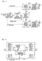
- Fig. 2 shows an encoder for two-channel stereophonic signals in accordance with an illustrative embodiment of the present invention.
- the operation of the illustrative encoder of Fig. 2 is similar to that of the prior art encoder shown in Fig. 1, except that, for each channel, a predictive filtering stage is introduced between the corresponding analysis filterbank and the intensity stereo encoding module. That is, predictive filters 16l and 16r are applied to the outputs of analysis filterbanks 12l and 12r, respectively.
- the spectral values, yl(b,0..,n-1) and yr(b,0...n-1), are replaced by the output values of the predictive filtering process, yl'(b,0...n-1) and yr'(b,0...n-1), respectively, before being provided to intensity stereo encoding module 13.
- Fig. 3 shows an illustrative implementation of the predictive filters of the illustrative encoder of Fig. 2.
- a linear prediction is performed across frequency (as opposed, for example, to predictive coding which is performed across time, such as is employed by subband-ADPCM coders).
- rotating switch operates to bring spectral values y(b,0...n-1) into a serial order prior to processing, and the resulting output values y'(b.0...n-1) are provided in parallel thereafter by "rotating switch” 46.
- the resultant output values. y'(b.0...n-1), are computed from the input values, y(b,0...n-1), by subtracting (with use of subtractor 48) the predicted value (predicted by predictor 47) from the input values, so that only the prediction error signal is passed on.
- the combination of predictor 47 and subtractor 48 labelled in the figure as envelope pre-whitening filter 44, functions to equalize the temporal shape of the corresponding time signal.
- the process performed by predictive filters 161 and 16r of the illustrative encoder of Fig. 2 can be performed either for the entire spectrum ( i.e., for all spectral coefficients), or, alternatively, for only a portion of the spectrum ( i.e., a subset of the spectral coefficients).
- different predictor filters e.g., different predictors 47 as shown in Fig. 3 can be used for different portions of the signal spectrum. In this manner, the above-described method for time-domain envelope control can be applied in any necessary frequency-dependent fashion.
- bitstream advantageously includes certain additional side information.
- one field of such information might indicate the use of predictive filtering and if applicable, the number of different prediction filters. If predictive filtering is used, additional fields in the bitstream may be transmitted for each prediction filter indicating the target frequency range of the respective filter and its filter coefficients.
- predictive filters 161 and 16r provide the necessary information to bitstream encoder/multiplexer 17 for inclusion in the transmitted bitstream.
- Fig. 7 shows a flow chart of a method of encoding two-channel stereophonic signals in accordance with an illustrative embodiment of the present invention.
- the illustrative example shown in this flow chart implements certain relevant portions of the illustrative encoder of Fig. 2.
- the flow chart shows the front-end portion of the encoder for a single one of the channels, including the envelope pre-whitening process using a single prediction filter. This pre-whitening process is carried out after the calculation of the spectral values by the analysis filterbank, as shown in step 61 of the figure.
- the order of the prediction filter is set and the target frequency range is defined (step 62).
- These parameters may illustratively be set to a filter order of 15 and a target frequency range comprising the entire frequency range that will be coded using intensity stereo coding (e.g., from 4 kHz to 20 kHz).
- intensity stereo coding e.g., from 4 kHz to 20 kHz.
- the scheme is advantageously configured to provide one set of individual fine temporal structure data for each audio channel.
- the prediction filter is determined by using the range of spectral coefficients matching the target frequency range, and by applying a conventional method for predictive coding as is well known, for example, in the context of Differential Pulse Code Modulation (DPCM) coders.
- DPCM Differential Pulse Code Modulation
- the autocorrelation function of the coefficients may be calculated and used in a conventional Levinson-Durbin recursion algorithm, well known to those skilled in the art.
- the predictor filter coefficients, the corresponding reflection coefficients ("PARCOR" coefficients), and the expected prediction gain are known.
- the predictive filtering procedure of steps 65 through 67 is used.
- the prediction filter coefficients are quantized (in step 65) as required for transmission to the decoder as part of the side information.
- the prediction filter is applied to the range of spectral coefficients matching the target frequency range where the quantized filter coefficients are used. For all further processing, therefore, the spectral coefficients are replaced by the output of the filtering process.
- a field of the bitstream to be transmitted is set to indicate the use of predictive filtering ("prediction flag" on).
- the target frequency range, the order of the prediction filter, and information describing its filter coefficients are also included in the bitstream.
- step 68 sets a field in the bitstream to indicate that no predictive filtering has been used ("prediction flag" off).
- Fig. 4 shows a prior art decoder for joint stereo coded signals, corresponding to the prior art encoder of Fig. 1, in which conventional intensity stereo coding techniques are employed. Specifically, the decoder of Fig. 4 performs the following steps:
- Fig. 5 shows a decoder for joint stereo coded signals, corresponding to the illustrative encoder of Fig. 2, in accordance with an illustrative embodiment of the present invention.
- the operation of the illustrative decoder of Fig. 5 is similar to that of the prior art decoder shown in Fig. 4, except that, for each channel, an inverse predictive filtering stage is introduced between the intensity stereo decoding and the corresponding synthesis filterbanks. That is, inverse predictive filters 261 and 26r are inserted prior to synthesis filterbanks 241 and 24r, respectively.
- the spectral values, yql() and yqr(), as generated by intensity stereo decoding module 23, are replaced by the output values of the corresponding inverse predictive filtering processes, yql'() and yqr'(), respectively, before being provided to their corresponding synthesis filterbanks (synthesis filterbanks 24l and 24r).
- Fig. 6 shows an illustrative implementation of the inverse predictive filters of the illustrative decoder of Fig. 5. Specifically, within the inverse predictive filters, a linear filtering operation is performed across (as opposed to performing predictive coding across time as in subband-ADPCM coders). In a similar manner to that shown in the prediction filter implementation of Fig. 3, "rotating switch" 33 of Fig. 6 is used to bring the spectral values yq(b,0 ... n-1) into a serial order prior to processing, and "rotating switch” 36 of the figure is used to bring the resulting output values yq'(b,0 ... n-1) into a parallel order thereafter.
- the output values, yq'(b.0 ... n-1), are computed from the input values, yq(b,0 ... n-1), by applying the inverse of the envelope pre-whitening filter used in the corresponding encoder.
- the output values are computed from the input values by adding (with use of adder 38) the predicted values (predicted by predictor 37) to the input values as shown.
- the combination of predictor 37 and adder 38 labelled in the figure as envelope shaping filter 34, functions to re-introduce the temporal shape of the original time signal.
- the above-described filtering process can be performed either for the entire spectrum ( i.e., for all spectral coefficients), or for only a portion of the spectrum ( i.e., a subset of the spectral coefficients).
- different predictor filters e.g., different predictors 37 as shown in Fig. 6
- Fig. 8 shows a flow chart of a method of decoding joint stereo coded signals, corresponding to the illustrative encoding method shown in Fig. 7, in accordance with an illustrative embodiment of the present invention.
- the illustrative example shown in this flow chart implements certain relevant portions of the illustrative decoder of Fig. 5.
- the flow chart shows the back-end portion of the decoder for a single one of the channels, including the envelope shaping process using a single (inverse) prediction filter.
- the processing which is performed by the decoder prior to those steps shown in the flow chart of Fig. 8 comprises conventional steps performed in prior art decoders (such as those carried out by the decoder of Fig.
- bitstream decoder/demultiplexer 25 of the illustrative decoder of Fig. 5 replaces conventional bitstream decoder/demultiplexer 21 of the prior art decoder of Fig. 4, so that the additional side information provided by the encoder (e.g., "L Filter Data” and "R Filter Data”) may be advantageously decoded and provided to inverse predictive filters 26l and 26r.
- the data from the bitstream which signals the use of predictive filtering is checked (by decision 72). If the data indicates that predictive filtering was performed in the encoder (i.e., the "prediction flag" is on), then the extended decoding process of steps 73 and 74 is carried out. Specifically, the target frequency range of the prediction filtering, the order of the pre-whitening (prediction) filter, and information describing the coefficients of the filter are retrieved from the (previously decoded) side information (step 73). Then, the inverse (decoder) prediction filter (i.e., the envelope shaping filter) is applied to the range of spectral coefficients matching the target frequency range (step 74). In either case ( i.e. , whether predictive filtering was performed or not), the decoder processing completes by running the synthesis filterbank (for each channel) from the spectral coefficients (as processed by the envelope shaping filter, if applicable), as shown in step 75.
- the synthesis filterbank for each channel
- the spectral coefficients as processed
- a straightforward envelope shaping effect can be achieved for certain conventional block transforms including the Discrete Fourier Transform (DFT) or the Discrete Cosine Transform (DCT), both well-known to those of ordinary skill in the art.
- DFT Discrete Fourier Transform
- DCT Discrete Cosine Transform
- a perceptual coder in accordance with the present invention uses a critically subsampled filterbank with overlapping windows -- e.g., a conventional Modified Discrete Cosine Transform or another conventional filterbank based on Time Domain Aliasing Cancellation (TDAC) -- the resultant envelope shaping effect is subject to the time domain aliasing effects inherent in the filterbank.
- TDAC Time Domain Aliasing Cancellation
- the final filterbank output is obtained by applying a synthesis window to the output of each inverse transform and performing an overlap-add of these data segments, the undesired aliased components are attenuated depending on the synthesis window used.
- An appropriate strategy in the encoder can, for example, adaptively select a window with a low degree of overlap for critical signals, thereby providing improved frequency selectivity. The implementation details of such a strategy will be obvious to those skilled in the art.
Description
- The subject matter of this application is related to that of the U.S. Patent Application of J. Herre, entitled "Perceptual Noise Shaping in the Time Domain via LPC Prediction in the Frequency Domain," Ser. No. 08/585086, filed on January 16, 1996 and assigned to the assignee of the present invention and corresponding to EP-A-0 785 631 published on 23.07.97. "Perceptual Noise Shaping in the Time Domain via LPC Prediction in the Frequency Domain" is hereby incorporated by reference as if fully set forth herein.
- The present invention relates to the field of audio signal coding and more specifically to an improved method and apparatus for performing joint stereo coding of multi-channel audio signals.
- During the last several years so-called "perceptual audio coders" have been developed enabling the transmission and storage of high quality audio signals at bit rates of about 1/12 or less of the bit rate commonly used on a conventional Compact Disc medium (CD). Such coders exploit the irrelevancy contained in an audio signal due to the limitations of the human auditory system by coding the signal with only so much accuracy as is necessary to result in a perceptually indistinguishable reconstructed (i.e., decoded) signal. Standards have been established under various standards organizations such as the International Standardization Organization's Moving Picture Experts Group (ISO/MPEG) MPEG1 and MPEG2 audio standards. Perceptual audio coders are described in detail, for example, in U.S. Patent No. 5,285,498 issued to James D. Johnston on Feb. 8, 1994 and in U.S. Patent No. 5,341,457 issued to Joseph L. Hall II and James D. Johnston on Aug. 23, 1994, each of which is assigned to the assignee of the present invention.
- Generally, the structure of a perceptual audio coder for monophonic audio signals can be described as follows:
- The input samples are converted into a subsampled spectral representation using various types of filterbanks and transforms such as, for example, the well-known modified discrete cosine transform (MDCT), polyphase filterbanks or hybrid structures.
- Using a perceptual model, one or more time-dependent masking thresholds for the signal are estimated. These thresholds give the maximum coding error that can be introduced into the audio signal while still maintaining perceptually unimpaired signal quality. In particular, these masking thresholds may be individually determined on a sub-band by sub-band basis. That is, each coder frequency band, which comprises a grouping of one or more spectral coefficients, will be advantageously coded together based on a correspondingly determined masking threshold.
- The spectral values are quantized and coded (on a coder frequency band basis) according to the precision corresponding to the masking threshold estimates. In this way, the quantization noise may be hidden (i.e., masked) by the respective transmitted signal and is thereby not perceptible after decoding.
- Finally, all relevant information (e.g., coded spectral values and additional side information) is packed into a bitstream and transmitted to the decoder.
- The bitstream is decoded and parsed into coded spectral data and side information.
- The inverse quantization of the quantized spectral values is performed (on a frequency band basis corresponding to that used in the encoder).
- The spectral values are mapped back into a time domain representation using a synthesis filterbank.
- Using such a generic coder structure it is possible to efficiently exploit the irrelevancy contained in each signal due to the limitations of the human auditory system. Specifically, the spectrum of the quantization noise can be shaped according to the shape of the signal's noise masking threshold. In this way, the noise which results from the coding process can be "hidden" under the coded signal and, thus, perceptually transparent quality can be achieved at high compression rates.
- Perceptual coding techniques for monophonic signals have been successfully extended to the coding of two-channel or multichannel stereophonic signals. In particular, so-called "joint stereo" coding techniques have been introduced which perform joint signal processing on the input signals, rather than performing separate (i.e., independent) coding processes for each input signal. (Note that as used herein, as used generally, and as is well known to those of ordinary skill in the art, the words "stereo" and "stereophonic" refer to the use of two or more individual audio channels.)
- There are at least two advantages to the use of joint stereo coding techniques. First, the use of joint stereo coding methods provide for the ability to account for binaural psychoacoustic effects. And, second the required bit rate for the coding of stereophonic signals may be reduced significantly below the bit rate required to perform separate and independent encodings for each channel.
- Generally, the structure of a multi-channel stereophonic perceptual audio coder can be described as follows:
- The samples of each input signal are converted into a subsampled spectral representation using various types of filterbanks and transforms, such as, for example, the modified discrete cosine transform (MDCT), polyphase filterbanks or hybrid structures.
- Using a model, the time-dependent masking threshold of the signal is estimated for each channel. This gives the maximum coding error that can be introduced into the audio signal while still maintaining perceptually unimpaired signal quality.
- To perform joint stereo coding, portions of the spectral coefficient data are jointly processed to achieve a more efficient representation of the stereo signal. Depending on the joint stereo coding method employed. adjustments may be made to the masking thresholds as well.
- The spectral values are quantized and coded according to the precision corresponding to the masking threshold estimate(s). In this way, the quantization noise is hidden (i.e., masked) by the respective transmitted signal and is thereby not perceptible after decoding.
- Finally, all relevant information (i.e., the coded spectral values and additional side information) is packed into a bitstream and transmitted to the decoder.
- The bitstream is decoded and parsed into coded spectral data and side information.
- The inverse quantization of the quantized spectral values is carried out.
- The decoding process for the joint stereo processing is performed on the spectral values, thereby resulting in separate signals for each channel.
- The spectral values for each channel are mapped back into time domain representations using corresponding synthesis filterbanks.
- Currently, the two most commonly used joint stereo coding techniques are known as "Mid/Side" (M/S) stereo coding and "intensity" stereo coding. The structure and operation of a coder based on M/S stereo coding is described, for example, in U.S. Patent No. 5,285,498 (see above). Using this technique, binaural masking effects can be advantageously accounted for and in addition, a certain amount of signal-dependent gain may be achieved.
- The intensity stereo method, however, provides a higher potential for bit saving. In particular, this method exploits the limitations of the human auditory system at high frequencies (e.g., frequencies above 4 kHz), by transmitting only one set of spectral coefficients for all jointly coded channel signals, thereby achieving a significant savings in data rate. Coders based on the intensity stereo principle have been described in numerous references including
European Patent Application 0 497 413 A by R. Veldhuis et al., filed on January 24, 1992 and published on August 5, 1992, and (using different terminology) PCT patent application WO 92/12607 by M. Davis et al., filed on January 8, 1992 and published on July 23, 1992. - By applying joint stereo processing to the spectral coefficients prior to quantization. additional savings in terms of the required bit rate can be achieved. For the case of intensity stereo coding, some of these savings derive from the fact that the human auditory system is known to be insensitive to phase information at high frequencies (e.g., frequencies above 4 kHz). Due to the characteristics of human hair cells, signal envelopes are perceptually evaluated rather than the signal waveform itself. Thus, it is sufficient to code the envelope of these portions of a signal, rather than having to code its entire waveform. This may, for example, be accomplished by transmitting one common set of spectral coefficients (referred to herein as the "carrier signal") for all participating channels, rather than transmitting separate sets of coefficients for each channel. Then, in the decoder, the carrier signal is scaled independently for each signal channel to match its average envelope (or signal energy) for the respective coder block.
- The following processing steps are typically performed for intensity stereo encoding/decoding on a coder frequency band basis:
- From the spectral coefficients of all participating channels, one "carrier" signal is generated that is suited to represent the individual channel signals. This is usually done by forming linear combinations of the partial signals.
- Scaling information is extracted from the original signals describing the envelope or energy content in the particular coder frequency band.
- Both the carrier signal and the scaling information are transmitted to the decoder.
- In the decoder, the spectral coefficients of the carrier signal are reconstructed. The spectral coefficients for each channel are then calculated by scaling the carrier signal using the respective scaling information for each channel.
- As a result of this approach, only one set of spectral coefficients (i.e., the coefficients of the carrier signal) needs to be transmitted, together with a small amount of side information (i.e., the scaling information), instead of having to transmit a separate set of spectral components for each channel signal. For the two-channel stereo case, this results in a saving of almost 50% of the data rate for the intensity coded frequency regions.
- Despite the advantages of this approach, however, excessive or uncontrolled application of the intensity stereo coding technique can lead to deterioration in the perceived stereo image, because the detailed structure of the signals over time is not preserved for time periods smaller than the granularity of the coding scheme (e.g., 20ms per block). In particular, as a consequence of the use of a single carrier, all output signals which are reconstructed therefrom are necessarily scaled versions of each other. In other words, they have the same fine envelope structure for the duration of the coded block (e.g., 10-20ms). This does not present a significant problem for stationary signals or for signals having similar fine envelope structures in the intensity stereo coded channels.
- For transient signals with dissimilar envelopes in different channels, however, the original distribution of the envelope onsets between the coded channels cannot be recovered. For example, in a stereophonic recording of an applauding audience. the individual envelopes will be very different in the right and left channels due to the distinct clapping events happening at different times in both channels. Similar effects will occur for recordings by using stereophonic microphones, such that the spatial location of a sound source is, in essence, encoded as time differences or delays between the respective channel signals. Consequently, the stereo image quality of an intensity stereo coded/decoded signal will decrease significantly in these cases. The spatial impression tends to narrow, and the perceived stereo image tends to collapse into the center position. For critical signals, the achieved quality can no longer be considered acceptable.
- Several strategies have been proposed in order to avoid deterioration in the stereo image of an intensity stereo encoded/decoded signal. Since using intensity stereo coding involves the risk of affecting the stereo image, it has been proposed to use the technique only in cases when the coder runs out of bits, so that severe quantization distortions, which would be perceived by the listener as being even more annoying, can be avoided. Alternatively, an algorithm can be employed which detects dissimilarities in the fine temporal structures of the channels. If a mismatch in envelopes is detected, intensity stereo coding is not applied in the given block. Such an approach is described, for example, in "Intensity Stereo Coding" by J. Herre et al., 96th Audio Engineering Society Convention, Amsterdam. February 1994. However, it is an obvious drawback of the prior proposed solutions that the potential for bit savings can no longer be fully exploited, given that the intensity stereo coding is disabled for such signals.
- In accordance with an illustrative embodiment of the present invention, the drawbacks of prior art techniques are overcome by a method and apparatus for performing joint stereo coding of multi-channel audio signals using intensity stereo coding techniques. In particular, predictive filtering techniques are applied to the spectral coefficient data, thereby preserving the fine time structure of the output signal of each channel, while maintaining the benefit of the high bit rate savings offered by intensity stereo coding. In one illustrative embodiment of the present invention, a method for enhancing the perceived stereo image of intensity stereo encoded/decoded signals is provided by applying the following processing steps in an encoder for two-channel stereophonic signals:
- The input signal of each channel is decomposed into spectral coefficients by a high-resolution filterbank/transform.
- Using a model, the one or more time-dependent masking thresholds are estimated for each channel. This advantageously gives the maximum coding error that can be introduced into the audio signal while still maintaining perceptually unimpaired signal quality.
- For each channel, a filter performing linear prediction in frequency is applied at the filterbank outputs, such that the residual, rather than the actual filterbank output signal, is used for the steps which follow.
- Intensity stereo coding techniques are applied for coding both residual signals into one carrier signal.
- The spectral values of the carrier signal are quantized and coded according to the precision corresponding to the masking threshold estimate(s).
- All relevant information (i.e., the coded spectral values, intensity scaling data and prediction filter data for each channel, as well as additional side information) is packed into a bitstream and transmitted to the decoder.
- Similarly, a decoder for joint stereo encoded signals, corresponding to the above-described illustrative encoder and in accordance with another illustrative embodiment of the present invention, carries out the following processing steps:
- The bitstream is decoded and parsed into coded spectral data and side information.
- An inverse quantization of the quantized spectral values for the carrier signal is performed.
- Intensity stereo decoding is performed on the spectral values of the carrier signal, thereby producing (residual) signals for each channel.
- For each channel, inverse prediction filters, operating in frequency and corresponding to the prediction filters applied by the encoder used to encode the original signal, are applied to the residual signals.
- The values produced by the inverse prediction filters are mapped back into time domain representations using synthesis filterbanks.
-
- Fig. 1 shows a prior art encoder for two-channel stereophonic signals in which conventional intensity stereo coding techniques are employed.
- Fig. 2 shows an encoder for two-channel stereophonic signals in accordance with an illustrative embodiment of the present invention.
- Fig. 3 shows an illustrative implementation of the predictive filters of the illustrative encoder of Fig. 2.
- Fig. 4 shows a prior art decoder for joint stereo coded signals, corresponding to the prior art encoder of Fig. 1, in which conventional intensity stereo coding techniques are employed.
- Fig. 5 shows a decoder for joint stereo coded signals, corresponding to the illustrative encoder of Fig. 2, in accordance with an illustrative embodiment of the present invention.
- Fig. 6 shows an illustrative implementation of the inverse predictive filters of the illustrative decoder of Fig. 5.
- Fig. 7 shows a flow chart of a method of encoding two-channel stereophonic signals in accordance with an illustrative embodiment of the present invention.
- Fig. 8 shows a flow chart of a method of decoding joint stereo coded signals, corresponding to the illustrative encoding method shown in Fig. 7, in accordance with an illustrative embodiment of the present invention.
-
- The incorporation of a predictive filtering process into the encoder and decoder in accordance with certain illustrative embodiments of the present invention advantageously enhances the quality of the intensity stereo encoded/decoded signal by overcoming the limitation of prior art schemes whereby identical fine envelope structures are produced in all intensity stereo decoded channel signals. In particular, the illustrative encoding method overcomes the drawbacks of prior techniques by effectively extending the filterbank with the predictive filtering stage, such that the envelope information common over frequency is extracted as filter coefficients, and is, for the most part, stripped from the residual signal.
- Specifically, for each input channel signal, a linear prediction is carried out on its corresponding spectral coefficient data, wherein the linear prediction is performed over frequency. Since predictive coding is applied to spectral domain data, the relations known for classical predictions are valid with the time and frequency domains interchanged. For example, the prediction error signal ideally has a "flat" (square of the) envelope, as opposed to having a "flat" power spectrum (a "pre-whitening" filter effect). The fine temporal structure information for each channel signal is contained in its prediction filter coefficients. Thus, it can be assumed that the carrier signal used for intensity stereo coding will also have a flat envelope, since it is generated by forming linear combinations of the (filtered) channel signals.
- In a corresponding decoder in accordance with an illustrative embodiment of the present invention, each channel signal is re-scaled according to the transmitted scaling information, and the inverse filtering process is applied to the spectral coefficients. In this way, the inverse "pre-whitening" process is performed on the envelope of each decoded channel signal, effectively re-introducing the envelope information into the spectral coefficients. Since this is done individually for each channel, the extended encoding/decoding system is capable of reproducing different individual fine envelope structures for each channel signal. Note that, in effect, using a combination of filterbank and linear prediction in frequency is equivalent to using an adaptive filterbank matched to the envelope of the input signal. Since the process of envelope shaping a signal can be performed either for the entire spectrum of the signal or for only part thereof, this time-domain envelope control can be advantageously applied in any necessary frequency-dependent fashion.
- And in accordance with another embodiment of the present invention, the bitstream which is, for example, by the illustrative encoder described above (and described in further detail below with reference to Figs. 2, 3 and 7) may be advantageously stored on a storage medium such as a Compact Disc or a Digital Audio Tape, or stored in a semiconductor memory device. Such a storage medium may then be "read back" to supply the bitstream for subsequent decoding by, for example, the illustrative decoder described above (and described in further detail below with reference to Figs. 5, 6 and 8). In this manner, a substantial quantity of audio data (e.g., music) may be compressed onto the given storage medium without loss of (perceptual) quality in the reconstructed signal.
- Fig. 1 shows a prior art perceptual encoder for two-channel stereophonic signals in which conventional intensity stereo coding techniques are employed. The encoder of Fig. 1 operates as follows:
- The left and right input signals, xl(k) and xr(k), are each individually decomposed
into spectral coefficients by analysis filterbank/
transform modules 12l and 12r, respectively, resulting in corresponding sets of "n" spectral components, yl(b,0 ... n-1) and yr(b,0 ... n-1), respectively, for each analysis block b. where "n" is the number of spectral coefficients per analysis block (i.e., the block size). Each spectral component yl(b,i) or yr(b,i) is associated with an analysis frequency in accordance with the particular filterbank employed. - For each channel,
perceptual model 11l or 11r estimates the required coding precision for perceptually transparent quality of the encoded/decoded signal. This estimation data may, for example, be based on the minimum signal-to-noise ratio (SNR) required in each coder band, and is passed to the quantization/encoding module. - The spectral values for both the left and the right channel, yl(b,0 ... n-1) and yr(b,0
... n-1), are provided to intensity
stereo encoding module 13, which performs conventional intensity stereo encoding. For portions of the spectrum which are to be excluded from intensity stereo coding, the corresponding values of yl(b,0 ... n-1) and yr(b,0 ... n-1) may be passed directly to the quantization and coding stage. For portions of the spectrum which are to make use of intensity stereo coding (i.e., preferably the high-frequency portions thereof), the intensity stereo coding process is performed as follows. From each of the signals yl() and yr(), scaling information is extracted for each coder frequency band (e.g., peak amplitude or total energy), and a single carrier signal yi() is generated by combining the corresponding yl() and yr() values. Thus, for spectral portions coded in intensity stereo, only one set of values yi() for both channels, plus scaling side information for each channel, is provided to the quantization and coding stage. Alternatively, combined scaling information for both channels together with directional information can be used (along with the single carrier signal). - The spectral components at the output of the intensity stereo encoding stage,
consisting of separate values yl() and yr() and common values yi(), are quantized and
mapped to transmission symbols by quantization and
encoding module 14. This module takes into account the required coding precision as determined byperceptual models 11l and 11r. - The transmission symbol values generated by quantization and
encoding module 14, together with further side information, are passed to bitstream encoder/multiplexer 15 and are thereby transmitted in the encoded bitstream. For coder frequency bands which use intensity stereo coding, the scaling information delivered by intensitystereo encoding module 13 is also provided to bitstream encoder/multiplexer 15 and thereby transmitted in the encoded bitstream as well. - Fig. 2 shows an encoder for two-channel stereophonic signals in accordance with an illustrative embodiment of the present invention. The operation of the illustrative encoder of Fig. 2 is similar to that of the prior art encoder shown in Fig. 1, except that, for each channel, a predictive filtering stage is introduced between the corresponding analysis filterbank and the intensity stereo encoding module. That is,
predictive filters 16l and 16r are applied to the outputs ofanalysis filterbanks 12l and 12r, respectively. As such, the spectral values, yl(b,0..,n-1) and yr(b,0...n-1), are replaced by the output values of the predictive filtering process, yl'(b,0...n-1) and yr'(b,0...n-1), respectively, before being provided to intensitystereo encoding module 13. - Fig. 3 shows an illustrative implementation of the predictive filters of the illustrative encoder of Fig. 2. Specifically, inside the predictive filtering stage for each channel, a linear prediction is performed across frequency (as opposed, for example, to predictive coding which is performed across time, such as is employed by subband-ADPCM coders). To this end "rotating switch" 43 operates to bring spectral values y(b,0...n-1) into a serial order prior to processing, and the resulting output values y'(b.0...n-1) are provided in parallel thereafter by "rotating switch" 46. (Note that the use of "rotating switches" as a mechanism for conversion between serial and parallel orderings is used herein only for the purpose of convenience and ease of understanding. As will be obvious to those of ordinary skill in the art, no such physical switching device need be provided. Rather, conversions between serial and parallel orderings may be performed in any of a number of conventional ways familiar to those skilled in the art, including by the use of software alone.) Although the illustrative embodiment shown herein performs the processing of the spectral values in order of increasing frequency. alternative embodiments may, for example, perform the processing thereof in order of decreasing frequency. Other orderings are also possible, as would be clear to one of ordinary skill in the art.
- Specifically, as can be seen from the figure, the resultant output values. y'(b.0...n-1), are computed from the input values, y(b,0...n-1), by subtracting (with use of subtractor 48) the predicted value (predicted by predictor 47) from the input values, so that only the prediction error signal is passed on. Note that the combination of predictor 47 and subtractor 48, labelled in the figure as envelope
pre-whitening filter 44, functions to equalize the temporal shape of the corresponding time signal. - The process performed by
predictive filters - In order to enable the proper decoding of the signal the bitstream advantageously includes certain additional side information. For example, one field of such information might indicate the use of predictive filtering and if applicable, the number of different prediction filters. If predictive filtering is used, additional fields in the bitstream may be transmitted for each prediction filter indicating the target frequency range of the respective filter and its filter coefficients. Thus, as shown in Fig. 2 by the dashed lines labelled "L Filter Data" and "R Filter Data,"
predictive filters multiplexer 17 for inclusion in the transmitted bitstream. - Fig. 7 shows a flow chart of a method of encoding two-channel stereophonic signals in accordance with an illustrative embodiment of the present invention. The illustrative example shown in this flow chart implements certain relevant portions of the illustrative encoder of Fig. 2. Specifically, the flow chart shows the front-end portion of the encoder for a single one of the channels, including the envelope pre-whitening process using a single prediction filter. This pre-whitening process is carried out after the calculation of the spectral values by the analysis filterbank, as shown in
step 61 of the figure. - Specifically, after the analysis filterbank is run, the order of the prediction filter is set and the target frequency range is defined (step 62). These parameters may illustratively be set to a filter order of 15 and a target frequency range comprising the entire frequency range that will be coded using intensity stereo coding (e.g., from 4 kHz to 20 kHz). In this manner, the scheme is advantageously configured to provide one set of individual fine temporal structure data for each audio channel. In
step 63, the prediction filter is determined by using the range of spectral coefficients matching the target frequency range, and by applying a conventional method for predictive coding as is well known, for example, in the context of Differential Pulse Code Modulation (DPCM) coders. For example, the autocorrelation function of the coefficients may be calculated and used in a conventional Levinson-Durbin recursion algorithm, well known to those skilled in the art. As a result, the predictor filter coefficients, the corresponding reflection coefficients ("PARCOR" coefficients), and the expected prediction gain are known. - If the expected prediction gain exceeds a certain threshold (e.g., 2 dB), as determined by
decision 64, the predictive filtering procedure ofsteps 65 through 67 is used. In this case, the prediction filter coefficients are quantized (in step 65) as required for transmission to the decoder as part of the side information. Then, instep 66, the prediction filter is applied to the range of spectral coefficients matching the target frequency range where the quantized filter coefficients are used. For all further processing, therefore, the spectral coefficients are replaced by the output of the filtering process. Finally, instep 67, a field of the bitstream to be transmitted is set to indicate the use of predictive filtering ("prediction flag" on). In addition, the target frequency range, the order of the prediction filter, and information describing its filter coefficients are also included in the bitstream. - If, on the other hand, the expected prediction gain does not exceed the decision threshold as determined by
decision 64,step 68 sets a field in the bitstream to indicate that no predictive filtering has been used ("prediction flag" off). Finally, after the above-described processing is complete, conventional steps as performed in prior art encoders (such as those carried out by the encoder of Fig. 1) are performed -- that is, the intensity stereo encoding process is applied to the spectral coefficients (which may now be residual data), the results of the intensity stereo encoding process are quantized and encoded, and the actual bitstream to be transmitted is encoded for transmission (with the appropriate side information multiplexed therein). Note, however, that bitstream encoder/multiplexer 17 of the illustrative encoder of Fig. 2 replaces conventional bitstream encoder/multiplexer 15 of the prior art encoder of Fig. 1. so that the additional side information provided bypredictive filters - Fig. 4 shows a prior art decoder for joint stereo coded signals, corresponding to the prior art encoder of Fig. 1, in which conventional intensity stereo coding techniques are employed. Specifically, the decoder of Fig. 4 performs the following steps:
- The incoming bitstream is parsed by bitstream decoder/
demultiplexer 21, and the transmission symbols for the spectral coefficients are passed on to decoding andinverse quantization module 22, together with the quantization related side information. - In decoding and
inverse quantization module 22, the quantized spectral values, yql(), yqr() and yqi(), are reconstructed. These signals correspond to the independently coded left channel signal portion, the independently coded right channel signal portion, and the intensity stereo carrier signal, respectively. - From the reconstructed spectral values of the carrier signal and the transmitted
scaling information, the missing portions of the yql() and yqr() spectra for the left
and right channel signals are calculated with use of a conventional intensity stereo
decoding process, which is performed by intensity
stereo decoding module 23. At the output of this module, two complete (and independent) channel spectral signals, yql() and yqr(), corresponding to the left and right channels, respectively, are available. - Finally, each of the left and right channel spectral signals, yql() and yqr(), are
mapped back into a time domain representation by
synthesis filterbanks - Fig. 5 shows a decoder for joint stereo coded signals, corresponding to the illustrative encoder of Fig. 2, in accordance with an illustrative embodiment of the present invention. The operation of the illustrative decoder of Fig. 5 is similar to that of the prior art decoder shown in Fig. 4, except that, for each channel, an inverse predictive filtering stage is introduced between the intensity stereo decoding and the corresponding synthesis filterbanks. That is, inverse
predictive filters 261 and 26r are inserted prior tosynthesis filterbanks stereo decoding module 23, are replaced by the output values of the corresponding inverse predictive filtering processes, yql'() and yqr'(), respectively, before being provided to their corresponding synthesis filterbanks (synthesis filterbanks 24l and 24r). - Fig. 6 shows an illustrative implementation of the inverse predictive filters of the illustrative decoder of Fig. 5. Specifically, within the inverse predictive filters, a linear filtering operation is performed across (as opposed to performing predictive coding across time as in subband-ADPCM coders). In a similar manner to that shown in the prediction filter implementation of Fig. 3, "rotating switch" 33 of Fig. 6 is used to bring the spectral values yq(b,0 ... n-1) into a serial order prior to processing, and "rotating switch" 36 of the figure is used to bring the resulting output values yq'(b,0 ... n-1) into a parallel order thereafter. (Once again, note that the use of "rotating switches" as a mechanism for conversion between serial and parallel orderings is provided herein only for the purpose of convenience and ease of understanding. As will be obvious to those of ordinary skill in the art, no such physical switching device need be provided. Rather, conversions between serial and parallel orderings may be performed in any of a number of conventional ways familiar to those skilled in the art, including by the use of software alone.) Again, as in the case of the illustrative encoder described above, processing in order of increasing or decreasing frequency is possible, as well as other possible orderings obvious to those skilled in the art.
- Specifically, as can be seen from the figure, the output values, yq'(b.0 ... n-1), are computed from the input values, yq(b,0 ... n-1), by applying the inverse of the envelope pre-whitening filter used in the corresponding encoder. In particular, the output values are computed from the input values by adding (with use of adder 38) the predicted values (predicted by predictor 37) to the input values as shown. Note that the combination of
predictor 37 andadder 38, labelled in the figure asenvelope shaping filter 34, functions to re-introduce the temporal shape of the original time signal. - As described above in the discussion of the illustrative encoder of Figs. 2 and 3, the above-described filtering process can be performed either for the entire spectrum (i.e., for all spectral coefficients), or for only a portion of the spectrum (i.e., a subset of the spectral coefficients). Moreover, different predictor filters (e.g.,
different predictors 37 as shown in Fig. 6) can be used for different parts of the signal spectrum. In such a case (in order to execute the proper decoding of the signal), the illustrative decoder of Fig. 5 advantageously decodes from the bitstream the additional side information (labelled in the figure as "L Filter Data" and "R Filter Data") which had been transmitted by the encoder. and supplies this data to inversepredictive filters 26l and 26r. In this manner, predicative decoding can be applied in each specified target frequency range with a corresponding prediction filter. - Fig. 8 shows a flow chart of a method of decoding joint stereo coded signals, corresponding to the illustrative encoding method shown in Fig. 7, in accordance with an illustrative embodiment of the present invention. The illustrative example shown in this flow chart implements certain relevant portions of the illustrative decoder of Fig. 5. Specifically, the flow chart shows the back-end portion of the decoder for a single one of the channels, including the envelope shaping process using a single (inverse) prediction filter. The processing which is performed by the decoder prior to those steps shown in the flow chart of Fig. 8 comprises conventional steps performed in prior art decoders (such as those carried out by the decoder of Fig. 4) -- that is, the bitstream is decoded/demultiplexed, the resultant data is decoded and inverse quantized, and the intensity stereo decoding process is performed. Note, however, that bitstream decoder/
demultiplexer 25 of the illustrative decoder of Fig. 5 replaces conventional bitstream decoder/demultiplexer 21 of the prior art decoder of Fig. 4, so that the additional side information provided by the encoder (e.g., "L Filter Data" and "R Filter Data") may be advantageously decoded and provided to inversepredictive filters 26l and 26r. - After the intensity stereo decoding has been completed, the data from the bitstream which signals the use of predictive filtering is checked (by decision 72). If the data indicates that predictive filtering was performed in the encoder (i.e., the "prediction flag" is on), then the extended decoding process of
steps step 75. - Using the above-described process in accordance with the illustrative embodiments of the present invention (i.e., predictive filtering in the encoder and inverse filtering in the decoder), a straightforward envelope shaping effect can be achieved for certain conventional block transforms including the Discrete Fourier Transform (DFT) or the Discrete Cosine Transform (DCT), both well-known to those of ordinary skill in the art. If, for example, a perceptual coder in accordance with the present invention uses a critically subsampled filterbank with overlapping windows -- e.g., a conventional Modified Discrete Cosine Transform or another conventional filterbank based on Time Domain Aliasing Cancellation (TDAC) -- the resultant envelope shaping effect is subject to the time domain aliasing effects inherent in the filterbank. For example, in the case of a MDCT, one mirroring (i.e., aliasing) operation per window half takes place, and the fine envelope structure appears mirrored (i.e., aliased) within the left and the right half of the window after decoding, respectively. Since the final filterbank output is obtained by applying a synthesis window to the output of each inverse transform and performing an overlap-add of these data segments, the undesired aliased components are attenuated depending on the synthesis window used. Thus, it is advantageous to choose a filterbank window that exhibits only a small overlap between subsequent blocks, so that the temporal aliasing effect is minimized. An appropriate strategy in the encoder can, for example, adaptively select a window with a low degree of overlap for critical signals, thereby providing improved frequency selectivity. The implementation details of such a strategy will be obvious to those skilled in the art.
- Although a number of specific embodiments of this invention have been shown and described herein, it is to be understood that these embodiments are merely illustrative of the many possible specific arrangements which can be devised in application of the principles of the invention. For example, although the illustrative embodiments which have been shown and described herein have been limited to the encoding and decoding of stereophonic audio signals comprising only two channels, alternative embodiments which may be used for the encoding and decoding of stereophonic audio signals having more than two channels will be obvious to those of ordinary skill in the art based on the disclosure provided herein. In addition, numerous and varied other arrangements can be devised in accordance with these principles by those of ordinary skill in the art without departing from the scope of the invention.
Claims (20)
- A method of performing joint stereo coding of a multichannel audio signal to generate an encoded signal, the method comprising the steps of:(a) performing a spectral decomposition of a first audio channel signal into a plurality of first spectral component signals;(b) generating a first prediction signal representative of a prediction of one of said first spectral component signals, said prediction based on one or more other ones of said first spectral component signals;(c) comparing the first prediction signal with said one of said first spectral component signals to generate a first prediction error signal;(d) performing a spectral decomposition of a second audio channel signal into a plurality of second spectral component signals;(e) performing joint stereo coding of said one of said first spectral component signals and one of said second spectral component signals to generate a jointly coded spectral component signal, said coding based on the first prediction error signal; and(f) generating the encoded signal based on the jointly coded spectral component signal.
- The method of claim 1 further comprising the steps of:and wherein the step of performing joint stereo coding of said one of said first spectral component signals and said one of said second spectral component signals is further based on said second prediction error signal.(g) generating a second prediction signal representative of a prediction of said one of said second spectral component signals, said prediction based on one or more other ones of said second spectral component signals; and(h) comparing the second prediction signal with said one of said second spectral component signals to generate a second prediction error signal;
- The method of claim 1 wherein the step of performing joint stereo coding of said one of said first spectral component signals and said one of said second spectral component signals comprises performing intensity stereo coding of said one of said first spectral component signals and said one of said second spectral component signals.
- The method of claim 1 wherein the step of generating the encoded signal based on the jointly coded spectral component signal comprises quantizing the jointly coded spectral component signal.
- The method of claim 4 wherein said quantization of the jointly coded spectral component signal is based on a perceptual model.
- A method as claimed in any of the preceding claims further including the step of storing said encoded signal on a storage medium.
- The method of claim 6 wherein the storage medium comprises a compact disc.
- The method of claim 6 wherein the storage medium comprises a digital audio tape.
- The method of claim 6 wherein the storage medium comprises a semiconductor memory.
- A method of decoding an encoded signal to generate a reconstructed multichannel audio signal, the encoded signal comprising a joint stereo coding of an original multichannel audio signal, the method comprising the steps of:(a) performing joint stereo decoding of the encoded signal to generate a plurality of decoded channel signals, each decoded channel signal comprising a plurality of decoded spectral component prediction error signals;(b) generating a first spectral component signal based on one or more of said spectral component prediction error signals comprised in a first one of said decoded channel signals;(c) generating a first prediction signal representative of a prediction of a second spectral component signal, said prediction based on said first spectral component signal;(d) generating the second spectral component signal based on the first prediction signal and on one or more of said spectral component prediction error signals comprised in the first one of said decoded channel signals; and(e) generating a first channel of the reconstructed multi-channel audio signal based on the first and second spectral component signals.
- The method of claim 10 further comprising the steps of:(f) generating a third spectral component signal based on one or more of said spectral component prediction error signals comprised in a second one of said decoded channel signals;(g) generating a second prediction signal representative of a prediction of a fourth spectral component signal, said prediction based on said third spectral component signal;(h) generating the fourth spectral component signal based on the second prediction signal and on one or more of said spectral component prediction error signals comprised in the second one of said decoded channel signals; and(i) generating a second channel of the reconstructed multichannel audio signal based on the third and fourth spectral component signals.
- The method of claim 10 wherein the step of performing joint stereo decoding of the encoded signal comprises performing intensity stereo decoding of the encoded signal.
- An encoder for performing joint stereo coding of a multi-channel audio signal to generate an encoded signal, the encoder comprising:(a) a first filterbank (12l, 12r) which performs a spectral decomposition of a first audio channel signal into a plurality of first spectral component signals;(b) a first prediction filter (16l, 16r, 47) which generates a first prediction signal representative of a prediction of one of said first spectral component signals, said prediction filter responsive to one or more other ones of said first spectral component signals;(c) a first comparator (48) which compares the first prediction signal with said one of said first spectral component signals to generate a first prediction error signal;(d) a second filterbank (12l, 12r) which performs a spectral decomposition of a second audio channel signal into a plurality of second spectral component signals;(e) a joint stereo coder (13) which performs joint stereo coding of said one of said first spectral component signals and one of said second spectral component signals to generate a jointly coded spectral component signal, said coding based on the first prediction error signal; and(f) a coder (14) which generates the encoded signal based on the jointly coded spectral component signal.
- The encoder of claim 13 further comprising:and wherein the joint stereo coder performs joint stereo coding further based on said second prediction error signal.(g) a second prediction filter (16l, 16r, 47) which generates a second prediction signal representative of a prediction of said one of said second spectral component signals, said prediction based on one or more other ones of said second spectral component signals; and(h) a second comparator (48) which compares the second prediction signal with said one of said second spectral component signals to generate a second prediction error signal;
- The encoder of claim 13 wherein the joint stereo coder comprises an intensity stereo coder which performs intensity stereo coding of said one of said first spectral component signals and said one of said second spectral component signals.
- The encoder of claim 13 wherein the coder which generates the encoded signal based on the jointly coded spectral component signal comprises a quantizer which quantizes the jointly coded spectral component signal.
- The encoder of claim 16 wherein the quantizer is based on a perceptual model.
- A decoder for decoding an encoded signal to generate a reconstructed multichannel audio signal, the encoded signal comprising a joint stereo coding of an original multichannel audio signal, the method comprising:(a) a joint stereo decoder (23) which performs joint stereo decoding of the encoded signal to generate a plurality of decoded channel signals, each decoded channel signal comprising a plurality of decoded spectral component prediction error signals;(b) means for generating a first spectral component signal based on one or more of said spectral component prediction error signals comprised in a first one of said decoded channel signals;(c) a first prediction filter (26l, 26r) which generates a first prediction signal representative of a prediction of a second spectral component signal, said prediction based on said first spectral component signal;(d) means for generating the second spectral component signal based on the first prediction signal and on one or more of said spectral component prediction error signals comprised in the first one of said decoded channel signals; and(e) a first filterbank (24l, 24r) which generates a first channel of the reconstructed multichannel audio signal based on the first and second spectral component signals.
- The decoder of claim 18 further comprising:(f) means for generating a third spectral component signal based on one or more of said spectral component prediction error signals comprised in a second one of said decoded channel signals;(g) a second prediction filter which generates a second prediction signal representative of a prediction of a fourth spectral component signal, said prediction based on said third spectral component signal;(h) means for generating the fourth spectral component signal based on the second prediction signal and on one or more of said spectral component prediction error signals comprised in the second one of said decoded channel signals; and(i) a second filterbank which generates a second channel of the reconstructed multi-channel audio signal based on the third and fourth spectral component signals.
- The decoder of claim 18 wherein the joint stereo decoder comprises an intensity stereo decoder which performs intensity stereo decoding of the encoded signal.
Applications Claiming Priority (2)
| Application Number | Priority Date | Filing Date | Title |
|---|---|---|---|
| US08/621,762 US5812971A (en) | 1996-03-22 | 1996-03-22 | Enhanced joint stereo coding method using temporal envelope shaping |
| US621762 | 1996-03-22 |
Publications (3)
| Publication Number | Publication Date |
|---|---|
| EP0797324A2 EP0797324A2 (en) | 1997-09-24 |
| EP0797324A3 EP0797324A3 (en) | 2004-01-14 |
| EP0797324B1 true EP0797324B1 (en) | 2004-11-24 |
Family
ID=24491531
Family Applications (1)
| Application Number | Title | Priority Date | Filing Date |
|---|---|---|---|
| EP97301677A Expired - Lifetime EP0797324B1 (en) | 1996-03-22 | 1997-03-12 | Enhanced joint stereo coding method using temporal envelope shaping |
Country Status (5)
| Country | Link |
|---|---|
| US (1) | US5812971A (en) |
| EP (1) | EP0797324B1 (en) |
| JP (1) | JP3316159B2 (en) |
| CA (1) | CA2197128C (en) |
| DE (1) | DE69731677T2 (en) |
Cited By (4)
| Publication number | Priority date | Publication date | Assignee | Title |
|---|---|---|---|---|
| DE102006055737A1 (en) * | 2006-11-25 | 2008-05-29 | Deutsche Telekom Ag | Method for the scalable coding of stereo signals |
| US7447629B2 (en) | 2002-07-12 | 2008-11-04 | Koninklijke Philips Electronics N.V. | Audio coding |
| CN102388417A (en) * | 2009-03-17 | 2012-03-21 | 杜比国际公司 | Advanced stereo coding based on a combination of adaptively selectable left/right or mid/side stereo coding and of parametric stereo coding |
| RU2740074C1 (en) * | 2017-11-10 | 2021-01-11 | Фраунхофер-Гезелльшафт Цур Фердерунг Дер Ангевандтен Форшунг Е.Ф. | Temporal formation of noise |
Families Citing this family (110)
| Publication number | Priority date | Publication date | Assignee | Title |
|---|---|---|---|---|
| DE19628293C1 (en) * | 1996-07-12 | 1997-12-11 | Fraunhofer Ges Forschung | Encoding and decoding audio signals using intensity stereo and prediction |
| JP2891193B2 (en) * | 1996-08-16 | 1999-05-17 | 日本電気株式会社 | Wideband speech spectral coefficient quantizer |
| EP0879465B1 (en) * | 1996-11-07 | 2005-11-16 | Koninklijke Philips Electronics N.V. | Data processing of a bitstream signal |
| US5913191A (en) * | 1997-10-17 | 1999-06-15 | Dolby Laboratories Licensing Corporation | Frame-based audio coding with additional filterbank to suppress aliasing artifacts at frame boundaries |
| EP1046239B1 (en) * | 1997-12-19 | 2003-06-18 | STMicroelectronics Asia Pacific Pte Ltd. | Method and apparatus for phase estimation in a transform coder for high quality audio |
| EP1050113B1 (en) * | 1997-12-27 | 2002-03-13 | STMicroelectronics Asia Pacific Pte Ltd. | Method and apparatus for estimation of coupling parameters in a transform coder for high quality audio |
| SE519552C2 (en) | 1998-09-30 | 2003-03-11 | Ericsson Telefon Ab L M | Multichannel signal coding and decoding |
| US6463410B1 (en) * | 1998-10-13 | 2002-10-08 | Victor Company Of Japan, Ltd. | Audio signal processing apparatus |
| JP2003505810A (en) * | 1999-07-20 | 2003-02-12 | コーニンクレッカ フィリップス エレクトロニクス エヌ ヴィ | Record carrier for carrying stereo and data signals |
| EP1087557A3 (en) * | 1999-09-22 | 2005-01-19 | Matsushita Electric Industrial Co., Ltd. | Apparatus for transmitting digital audio data and receiving apparatus for receiving the digital audio data |
| DE19947877C2 (en) * | 1999-10-05 | 2001-09-13 | Fraunhofer Ges Forschung | Method and device for introducing information into a data stream and method and device for encoding an audio signal |
| US7742927B2 (en) * | 2000-04-18 | 2010-06-22 | France Telecom | Spectral enhancing method and device |
| ATE387044T1 (en) * | 2000-07-07 | 2008-03-15 | Nokia Siemens Networks Oy | METHOD AND APPARATUS FOR PERCEPTUAL TONE CODING OF A MULTI-CHANNEL TONE SIGNAL USING CASCADED DISCRETE COSINE TRANSFORMATION OR MODIFIED DISCRETE COSINE TRANSFORMATION |
| SE0004163D0 (en) * | 2000-11-14 | 2000-11-14 | Coding Technologies Sweden Ab | Enhancing perceptual performance or high frequency reconstruction coding methods by adaptive filtering |
| JP4618873B2 (en) * | 2000-11-24 | 2011-01-26 | パナソニック株式会社 | Audio signal encoding method, audio signal encoding device, music distribution method, and music distribution system |
| FR2821475B1 (en) * | 2001-02-23 | 2003-05-09 | France Telecom | METHOD AND DEVICE FOR SPECTRALLY RECONSTRUCTING MULTI-CHANNEL SIGNALS, ESPECIALLY STEREOPHONIC SIGNALS |
| US7583805B2 (en) * | 2004-02-12 | 2009-09-01 | Agere Systems Inc. | Late reverberation-based synthesis of auditory scenes |
| US20030035553A1 (en) * | 2001-08-10 | 2003-02-20 | Frank Baumgarte | Backwards-compatible perceptual coding of spatial cues |
| US7644003B2 (en) * | 2001-05-04 | 2010-01-05 | Agere Systems Inc. | Cue-based audio coding/decoding |
| US7116787B2 (en) * | 2001-05-04 | 2006-10-03 | Agere Systems Inc. | Perceptual synthesis of auditory scenes |
| US7292901B2 (en) * | 2002-06-24 | 2007-11-06 | Agere Systems Inc. | Hybrid multi-channel/cue coding/decoding of audio signals |
| US6934676B2 (en) * | 2001-05-11 | 2005-08-23 | Nokia Mobile Phones Ltd. | Method and system for inter-channel signal redundancy removal in perceptual audio coding |
| US7002618B2 (en) * | 2001-06-01 | 2006-02-21 | Stereographics Corporation | Plano-stereoscopic DVD movie |
| US6934677B2 (en) * | 2001-12-14 | 2005-08-23 | Microsoft Corporation | Quantization matrices based on critical band pattern information for digital audio wherein quantization bands differ from critical bands |
| US7240001B2 (en) * | 2001-12-14 | 2007-07-03 | Microsoft Corporation | Quality improvement techniques in an audio encoder |
| US6751587B2 (en) * | 2002-01-04 | 2004-06-15 | Broadcom Corporation | Efficient excitation quantization in noise feedback coding with general noise shaping |
| US7206740B2 (en) * | 2002-01-04 | 2007-04-17 | Broadcom Corporation | Efficient excitation quantization in noise feedback coding with general noise shaping |
| RU2316154C2 (en) * | 2002-04-10 | 2008-01-27 | Конинклейке Филипс Электроникс Н.В. | Method for encoding stereophonic signals |
| US7275036B2 (en) * | 2002-04-18 | 2007-09-25 | Fraunhofer-Gesellschaft Zur Foerderung Der Angewandten Forschung E.V. | Apparatus and method for coding a time-discrete audio signal to obtain coded audio data and for decoding coded audio data |
| AU2003216686A1 (en) * | 2002-04-22 | 2003-11-03 | Koninklijke Philips Electronics N.V. | Parametric multi-channel audio representation |
| US7502743B2 (en) * | 2002-09-04 | 2009-03-10 | Microsoft Corporation | Multi-channel audio encoding and decoding with multi-channel transform selection |
| US7299190B2 (en) * | 2002-09-04 | 2007-11-20 | Microsoft Corporation | Quantization and inverse quantization for audio |
| JP4676140B2 (en) * | 2002-09-04 | 2011-04-27 | マイクロソフト コーポレーション | Audio quantization and inverse quantization |
| DE60330198D1 (en) | 2002-09-04 | 2009-12-31 | Microsoft Corp | Entropic coding by adapting the coding mode between level and run length level mode |
| KR100501930B1 (en) * | 2002-11-29 | 2005-07-18 | 삼성전자주식회사 | Audio decoding method recovering high frequency with small computation and apparatus thereof |
| US20060171542A1 (en) * | 2003-03-24 | 2006-08-03 | Den Brinker Albertus C | Coding of main and side signal representing a multichannel signal |
| US7318035B2 (en) * | 2003-05-08 | 2008-01-08 | Dolby Laboratories Licensing Corporation | Audio coding systems and methods using spectral component coupling and spectral component regeneration |
| US7447317B2 (en) | 2003-10-02 | 2008-11-04 | Fraunhofer-Gesellschaft Zur Foerderung Der Angewandten Forschung E.V | Compatible multi-channel coding/decoding by weighting the downmix channel |
| SE527670C2 (en) * | 2003-12-19 | 2006-05-09 | Ericsson Telefon Ab L M | Natural fidelity optimized coding with variable frame length |
| US7809579B2 (en) * | 2003-12-19 | 2010-10-05 | Telefonaktiebolaget Lm Ericsson (Publ) | Fidelity-optimized variable frame length encoding |
| US7725324B2 (en) * | 2003-12-19 | 2010-05-25 | Telefonaktiebolaget Lm Ericsson (Publ) | Constrained filter encoding of polyphonic signals |
| US7460990B2 (en) | 2004-01-23 | 2008-12-02 | Microsoft Corporation | Efficient coding of digital media spectral data using wide-sense perceptual similarity |
| DE102004009954B4 (en) * | 2004-03-01 | 2005-12-15 | Fraunhofer-Gesellschaft zur Förderung der angewandten Forschung e.V. | Apparatus and method for processing a multi-channel signal |
| US7805313B2 (en) * | 2004-03-04 | 2010-09-28 | Agere Systems Inc. | Frequency-based coding of channels in parametric multi-channel coding systems |
| US7653255B2 (en) | 2004-06-02 | 2010-01-26 | Adobe Systems Incorporated | Image region of interest encoding |
| EP1761915B1 (en) * | 2004-06-21 | 2008-12-03 | Koninklijke Philips Electronics N.V. | Method and apparatus to encode and decode multi-channel audio signals |
| WO2006008697A1 (en) * | 2004-07-14 | 2006-01-26 | Koninklijke Philips Electronics N.V. | Audio channel conversion |
| PL2175671T3 (en) * | 2004-07-14 | 2012-10-31 | Koninl Philips Electronics Nv | Method, device, encoder apparatus, decoder apparatus and audio system |
| TWI497485B (en) | 2004-08-25 | 2015-08-21 | Dolby Lab Licensing Corp | Method for reshaping the temporal envelope of synthesized output audio signal to approximate more closely the temporal envelope of input audio signal |
| AU2012205170B2 (en) * | 2004-08-25 | 2015-05-14 | Dolby Laboratories Licensing Corporation | Temporal Envelope Shaping for Spatial Audio Coding using Frequency Domain Weiner Filtering |
| TWI393121B (en) * | 2004-08-25 | 2013-04-11 | Dolby Lab Licensing Corp | Method and apparatus for processing a set of n audio signals, and computer program associated therewith |
| BRPI0514998A (en) * | 2004-08-26 | 2008-07-01 | Matsushita Electric Ind Co Ltd | multi channel signal coding equipment and multi channel signal decoding equipment |
| US7895034B2 (en) * | 2004-09-17 | 2011-02-22 | Digital Rise Technology Co., Ltd. | Audio encoding system |
| US7720230B2 (en) * | 2004-10-20 | 2010-05-18 | Agere Systems, Inc. | Individual channel shaping for BCC schemes and the like |
| US8204261B2 (en) * | 2004-10-20 | 2012-06-19 | Fraunhofer-Gesellschaft Zur Foerderung Der Angewandten Forschung E.V. | Diffuse sound shaping for BCC schemes and the like |
| US7787631B2 (en) * | 2004-11-30 | 2010-08-31 | Agere Systems Inc. | Parametric coding of spatial audio with cues based on transmitted channels |
| WO2006060279A1 (en) * | 2004-11-30 | 2006-06-08 | Agere Systems Inc. | Parametric coding of spatial audio with object-based side information |
| DE602005017302D1 (en) | 2004-11-30 | 2009-12-03 | Agere Systems Inc | SYNCHRONIZATION OF PARAMETRIC ROOM TONE CODING WITH EXTERNALLY DEFINED DOWNMIX |
| US7903824B2 (en) * | 2005-01-10 | 2011-03-08 | Agere Systems Inc. | Compact side information for parametric coding of spatial audio |
| EP1691348A1 (en) * | 2005-02-14 | 2006-08-16 | Ecole Polytechnique Federale De Lausanne | Parametric joint-coding of audio sources |
| US9626973B2 (en) * | 2005-02-23 | 2017-04-18 | Telefonaktiebolaget L M Ericsson (Publ) | Adaptive bit allocation for multi-channel audio encoding |
| ATE521143T1 (en) * | 2005-02-23 | 2011-09-15 | Ericsson Telefon Ab L M | ADAPTIVE BIT ALLOCATION FOR MULTI-CHANNEL AUDIO ENCODING |
| DE102005010057A1 (en) * | 2005-03-04 | 2006-09-07 | Fraunhofer-Gesellschaft zur Förderung der angewandten Forschung e.V. | Apparatus and method for generating a coded stereo signal of an audio piece or audio data stream |
| KR100818268B1 (en) | 2005-04-14 | 2008-04-02 | 삼성전자주식회사 | Apparatus and method for audio encoding/decoding with scalability |
| EP1829424B1 (en) | 2005-04-15 | 2009-01-21 | Dolby Sweden AB | Temporal envelope shaping of decorrelated signals |
| US7983922B2 (en) * | 2005-04-15 | 2011-07-19 | Fraunhofer-Gesellschaft Zur Foerderung Der Angewandten Forschung E.V. | Apparatus and method for generating multi-channel synthesizer control signal and apparatus and method for multi-channel synthesizing |
| BRPI0611505A2 (en) * | 2005-06-03 | 2010-09-08 | Dolby Lab Licensing Corp | channel reconfiguration with secondary information |
| US7693709B2 (en) * | 2005-07-15 | 2010-04-06 | Microsoft Corporation | Reordering coefficients for waveform coding or decoding |
| US7599840B2 (en) | 2005-07-15 | 2009-10-06 | Microsoft Corporation | Selectively using multiple entropy models in adaptive coding and decoding |
| US7539612B2 (en) * | 2005-07-15 | 2009-05-26 | Microsoft Corporation | Coding and decoding scale factor information |
| US7565018B2 (en) * | 2005-08-12 | 2009-07-21 | Microsoft Corporation | Adaptive coding and decoding of wide-range coefficients |
| US7933337B2 (en) * | 2005-08-12 | 2011-04-26 | Microsoft Corporation | Prediction of transform coefficients for image compression |
| CN101427307B (en) * | 2005-09-27 | 2012-03-07 | Lg电子株式会社 | Method and apparatus for encoding/decoding multi-channel audio signal |
| EP1943642A4 (en) * | 2005-09-27 | 2009-07-01 | Lg Electronics Inc | Method and apparatus for encoding/decoding multi-channel audio signal |
| US7974713B2 (en) * | 2005-10-12 | 2011-07-05 | Fraunhofer-Gesellschaft Zur Foerderung Der Angewandten Forschung E.V. | Temporal and spatial shaping of multi-channel audio signals |
| US7831434B2 (en) * | 2006-01-20 | 2010-11-09 | Microsoft Corporation | Complex-transform channel coding with extended-band frequency coding |
| US8190425B2 (en) * | 2006-01-20 | 2012-05-29 | Microsoft Corporation | Complex cross-correlation parameters for multi-channel audio |
| US7953604B2 (en) * | 2006-01-20 | 2011-05-31 | Microsoft Corporation | Shape and scale parameters for extended-band frequency coding |
| US7590523B2 (en) * | 2006-03-20 | 2009-09-15 | Mindspeed Technologies, Inc. | Speech post-processing using MDCT coefficients |
| KR100754937B1 (en) * | 2006-03-30 | 2007-09-03 | 인하대학교 산학협력단 | A multi-step channel prediction apparatus and method for adaptive transmission in ofdm/fdd system |
| US20090276210A1 (en) * | 2006-03-31 | 2009-11-05 | Panasonic Corporation | Stereo audio encoding apparatus, stereo audio decoding apparatus, and method thereof |
| KR100718416B1 (en) | 2006-06-28 | 2007-05-14 | 주식회사 대우일렉트로닉스 | Method for coding stereo audio signal between channels using prediction filter |
| US7797155B2 (en) * | 2006-07-26 | 2010-09-14 | Ittiam Systems (P) Ltd. | System and method for measurement of perceivable quantization noise in perceptual audio coders |
| CN101169934B (en) * | 2006-10-24 | 2011-05-11 | 华为技术有限公司 | Time domain hearing threshold weighting filter construction method and apparatus, encoder and decoder |
| US8184710B2 (en) | 2007-02-21 | 2012-05-22 | Microsoft Corporation | Adaptive truncation of transform coefficient data in a transform-based digital media codec |
| US8983830B2 (en) | 2007-03-30 | 2015-03-17 | Panasonic Intellectual Property Corporation Of America | Stereo signal encoding device including setting of threshold frequencies and stereo signal encoding method including setting of threshold frequencies |
| US7761290B2 (en) | 2007-06-15 | 2010-07-20 | Microsoft Corporation | Flexible frequency and time partitioning in perceptual transform coding of audio |
| US8046214B2 (en) * | 2007-06-22 | 2011-10-25 | Microsoft Corporation | Low complexity decoder for complex transform coding of multi-channel sound |
| US7885819B2 (en) | 2007-06-29 | 2011-02-08 | Microsoft Corporation | Bitstream syntax for multi-process audio decoding |
| US8249883B2 (en) | 2007-10-26 | 2012-08-21 | Microsoft Corporation | Channel extension coding for multi-channel source |
| WO2009057327A1 (en) * | 2007-10-31 | 2009-05-07 | Panasonic Corporation | Encoder and decoder |
| JP5404412B2 (en) | 2007-11-01 | 2014-01-29 | パナソニック株式会社 | Encoding device, decoding device and methods thereof |
| US8179974B2 (en) | 2008-05-02 | 2012-05-15 | Microsoft Corporation | Multi-level representation of reordered transform coefficients |
| MX2011000375A (en) * | 2008-07-11 | 2011-05-19 | Fraunhofer Ges Forschung | Audio encoder and decoder for encoding and decoding frames of sampled audio signal. |
| KR101546793B1 (en) | 2008-07-14 | 2015-08-28 | 삼성전자주식회사 | / method and apparatus for encoding/decoding audio signal |
| US8406307B2 (en) | 2008-08-22 | 2013-03-26 | Microsoft Corporation | Entropy coding/decoding of hierarchically organized data |
| WO2010140350A1 (en) * | 2009-06-02 | 2010-12-09 | パナソニック株式会社 | Down-mixing device, encoder, and method therefor |
| US20100324915A1 (en) * | 2009-06-23 | 2010-12-23 | Electronic And Telecommunications Research Institute | Encoding and decoding apparatuses for high quality multi-channel audio codec |
| EP3582217B1 (en) * | 2010-04-09 | 2022-11-09 | Dolby International AB | Stereo coding using either a prediction mode or a non-prediction mode |
| US9311923B2 (en) * | 2011-05-19 | 2016-04-12 | Dolby Laboratories Licensing Corporation | Adaptive audio processing based on forensic detection of media processing history |
| US8401863B1 (en) * | 2012-04-25 | 2013-03-19 | Dolby Laboratories Licensing Corporation | Audio encoding and decoding with conditional quantizers |
| EP3067887A1 (en) * | 2015-03-09 | 2016-09-14 | Fraunhofer-Gesellschaft zur Förderung der angewandten Forschung e.V. | Audio encoder for encoding a multichannel signal and audio decoder for decoding an encoded audio signal |
| WO2019091576A1 (en) | 2017-11-10 | 2019-05-16 | Fraunhofer-Gesellschaft zur Förderung der angewandten Forschung e.V. | Audio encoders, audio decoders, methods and computer programs adapting an encoding and decoding of least significant bits |
| EP3483882A1 (en) | 2017-11-10 | 2019-05-15 | Fraunhofer-Gesellschaft zur Förderung der angewandten Forschung e.V. | Controlling bandwidth in encoders and/or decoders |
| EP3483886A1 (en) | 2017-11-10 | 2019-05-15 | Fraunhofer-Gesellschaft zur Förderung der angewandten Forschung e.V. | Selecting pitch lag |
| EP3483883A1 (en) | 2017-11-10 | 2019-05-15 | Fraunhofer-Gesellschaft zur Förderung der angewandten Forschung e.V. | Audio coding and decoding with selective postfiltering |
| WO2019091573A1 (en) | 2017-11-10 | 2019-05-16 | Fraunhofer-Gesellschaft zur Förderung der angewandten Forschung e.V. | Apparatus and method for encoding and decoding an audio signal using downsampling or interpolation of scale parameters |
| EP3483878A1 (en) | 2017-11-10 | 2019-05-15 | Fraunhofer-Gesellschaft zur Förderung der angewandten Forschung e.V. | Audio decoder supporting a set of different loss concealment tools |
| EP3483884A1 (en) | 2017-11-10 | 2019-05-15 | Fraunhofer-Gesellschaft zur Förderung der angewandten Forschung e.V. | Signal filtering |
| EP3483879A1 (en) | 2017-11-10 | 2019-05-15 | Fraunhofer-Gesellschaft zur Förderung der angewandten Forschung e.V. | Analysis/synthesis windowing function for modulated lapped transformation |
Family Cites Families (11)
| Publication number | Priority date | Publication date | Assignee | Title |
|---|---|---|---|---|
| SE457402B (en) * | 1987-02-20 | 1988-12-19 | Harald Brusewitz | PROCEDURE AND DEVICE FOR CODING AND DECODING IMAGE INFORMATION |
| US4875095A (en) * | 1987-06-30 | 1989-10-17 | Kokusai Denshin Denwa Kabushiki Kaisha | Noise-shaping predictive coding system |
| US4943855A (en) * | 1988-07-22 | 1990-07-24 | At&T Bell Laboratories | Progressive sub-band image coding system |
| US5341457A (en) * | 1988-12-30 | 1994-08-23 | At&T Bell Laboratories | Perceptual coding of audio signals |
| ES2087522T3 (en) * | 1991-01-08 | 1996-07-16 | Dolby Lab Licensing Corp | DECODING / CODING FOR MULTIDIMENSIONAL SOUND FIELDS. |
| NL9100173A (en) * | 1991-02-01 | 1992-09-01 | Philips Nv | SUBBAND CODING DEVICE, AND A TRANSMITTER EQUIPPED WITH THE CODING DEVICE. |
| US5285498A (en) * | 1992-03-02 | 1994-02-08 | At&T Bell Laboratories | Method and apparatus for coding audio signals based on perceptual model |
| JP2693893B2 (en) * | 1992-03-30 | 1997-12-24 | 松下電器産業株式会社 | Stereo speech coding method |
| DE4320990B4 (en) * | 1993-06-05 | 2004-04-29 | Robert Bosch Gmbh | Redundancy reduction procedure |
| DE4331376C1 (en) * | 1993-09-15 | 1994-11-10 | Fraunhofer Ges Forschung | Method for determining the type of encoding to selected for the encoding of at least two signals |
| DE4409368A1 (en) * | 1994-03-18 | 1995-09-21 | Fraunhofer Ges Forschung | Method for encoding multiple audio signals |
-
1996
- 1996-03-22 US US08/621,762 patent/US5812971A/en not_active Expired - Lifetime
-
1997
- 1997-02-10 CA CA002197128A patent/CA2197128C/en not_active Expired - Lifetime
- 1997-03-12 DE DE69731677T patent/DE69731677T2/en not_active Expired - Lifetime
- 1997-03-12 EP EP97301677A patent/EP0797324B1/en not_active Expired - Lifetime
- 1997-03-18 JP JP06405297A patent/JP3316159B2/en not_active Expired - Lifetime
Cited By (7)
| Publication number | Priority date | Publication date | Assignee | Title |
|---|---|---|---|---|
| US7447629B2 (en) | 2002-07-12 | 2008-11-04 | Koninklijke Philips Electronics N.V. | Audio coding |
| DE102006055737A1 (en) * | 2006-11-25 | 2008-05-29 | Deutsche Telekom Ag | Method for the scalable coding of stereo signals |
| CN102388417A (en) * | 2009-03-17 | 2012-03-21 | 杜比国际公司 | Advanced stereo coding based on a combination of adaptively selectable left/right or mid/side stereo coding and of parametric stereo coding |
| CN102388417B (en) * | 2009-03-17 | 2015-10-21 | 杜比国际公司 | Based on the senior stereo coding of the combination of selectable left/right or central authorities/side stereo coding and parameter stereo coding adaptively |
| US10297259B2 (en) | 2009-03-17 | 2019-05-21 | Dolby International Ab | Advanced stereo coding based on a combination of adaptively selectable left/right or mid/side stereo coding and of parametric stereo coding |
| RU2740074C1 (en) * | 2017-11-10 | 2021-01-11 | Фраунхофер-Гезелльшафт Цур Фердерунг Дер Ангевандтен Форшунг Е.Ф. | Temporal formation of noise |
| US11127408B2 (en) | 2017-11-10 | 2021-09-21 | Fraunhofer—Gesellschaft zur F rderung der angewandten Forschung e.V. | Temporal noise shaping |
Also Published As
| Publication number | Publication date |
|---|---|
| JP3316159B2 (en) | 2002-08-19 |
| EP0797324A2 (en) | 1997-09-24 |
| EP0797324A3 (en) | 2004-01-14 |
| DE69731677T2 (en) | 2005-12-15 |
| JPH1051313A (en) | 1998-02-20 |
| US5812971A (en) | 1998-09-22 |
| CA2197128A1 (en) | 1997-09-23 |
| CA2197128C (en) | 2000-04-11 |
| DE69731677D1 (en) | 2004-12-30 |
Similar Documents
| Publication | Publication Date | Title |
|---|---|---|
| EP0797324B1 (en) | Enhanced joint stereo coding method using temporal envelope shaping | |
| EP0785631B1 (en) | Perceptual noise shaping in the time domain via LPC prediction in the frequency domain | |
| KR100346066B1 (en) | Method for coding an audio signal | |
| RU2730469C2 (en) | Improved stereo coding based on a combination of adaptively selected left/right or middle/side stereophonic coding and parametric stereophonic coding | |
| US5488665A (en) | Multi-channel perceptual audio compression system with encoding mode switching among matrixed channels | |
| JP3258424B2 (en) | Speech signal coding method and device based on perceptual model | |
| KR100947013B1 (en) | Temporal and spatial shaping of multi-channel audio signals | |
| CA2301663C (en) | A method and a device for coding audio signals and a method and a device for decoding a bit stream | |
| JP2923406B2 (en) | Audio signal processing method | |
| KR970007663B1 (en) | Rate control loop processor for perceptual encoder/decoder | |
| US6061649A (en) | Signal encoding method and apparatus, signal decoding method and apparatus and signal transmission apparatus | |
| US5581654A (en) | Method and apparatus for information encoding and decoding | |
| JP2019506633A (en) | Apparatus and method for MDCT M / S stereo with comprehensive ILD with improved mid / side decision | |
| US7725324B2 (en) | Constrained filter encoding of polyphonic signals | |
| EP1175030B1 (en) | Method and system for multichannel perceptual audio coding using the cascaded discrete cosine transform or modified discrete cosine transform | |
| KR100528325B1 (en) | Scalable stereo audio coding/encoding method and apparatus thereof | |
| US5758316A (en) | Methods and apparatus for information encoding and decoding based upon tonal components of plural channels | |
| RU2798024C1 (en) | Audio upmixing device performed with the possibility of operating in the mode with/without prediction | |
| EP1639580B1 (en) | Coding of multi-channel signals | |
| Noll | Digital audio for multimedia | |
| Noll | Wideband Audio |
Legal Events
| Date | Code | Title | Description |
|---|---|---|---|
| PUAI | Public reference made under article 153(3) epc to a published international application that has entered the european phase |
Free format text: ORIGINAL CODE: 0009012 |
|
| AK | Designated contracting states |
Kind code of ref document: A2 Designated state(s): DE FR GB |
|
| 17P | Request for examination filed |
Effective date: 20030811 |
|
| PUAL | Search report despatched |
Free format text: ORIGINAL CODE: 0009013 |
|
| AK | Designated contracting states |
Kind code of ref document: A3 Designated state(s): DE FR GB |
|
| GRAP | Despatch of communication of intention to grant a patent |
Free format text: ORIGINAL CODE: EPIDOSNIGR1 |
|
| GRAS | Grant fee paid |
Free format text: ORIGINAL CODE: EPIDOSNIGR3 |
|
| GRAA | (expected) grant |
Free format text: ORIGINAL CODE: 0009210 |
|
| AK | Designated contracting states |
Kind code of ref document: B1 Designated state(s): DE FR GB |
|
| REG | Reference to a national code |
Ref country code: GB Ref legal event code: FG4D |
|
| REF | Corresponds to: |
Ref document number: 69731677 Country of ref document: DE Date of ref document: 20041230 Kind code of ref document: P |
|
| PLBE | No opposition filed within time limit |
Free format text: ORIGINAL CODE: 0009261 |
|
| STAA | Information on the status of an ep patent application or granted ep patent |
Free format text: STATUS: NO OPPOSITION FILED WITHIN TIME LIMIT |
|
| ET | Fr: translation filed | ||
| 26N | No opposition filed |
Effective date: 20050825 |
|
| REG | Reference to a national code |
Ref country code: GB Ref legal event code: 732E Free format text: REGISTERED BETWEEN 20131121 AND 20131127 |
|
| REG | Reference to a national code |
Ref country code: FR Ref legal event code: CD Owner name: ALCATEL-LUCENT USA INC. Effective date: 20131122 |
|
| REG | Reference to a national code |
Ref country code: FR Ref legal event code: GC Effective date: 20140410 |
|
| REG | Reference to a national code |
Ref country code: FR Ref legal event code: RG Effective date: 20141015 |
|
| REG | Reference to a national code |
Ref country code: FR Ref legal event code: PLFP Year of fee payment: 19 |
|
| PGFP | Annual fee paid to national office [announced via postgrant information from national office to epo] |
Ref country code: DE Payment date: 20150320 Year of fee payment: 19 |
|
| PGFP | Annual fee paid to national office [announced via postgrant information from national office to epo] |
Ref country code: GB Payment date: 20150319 Year of fee payment: 19 Ref country code: FR Payment date: 20150319 Year of fee payment: 19 |
|
| REG | Reference to a national code |
Ref country code: DE Ref legal event code: R119 Ref document number: 69731677 Country of ref document: DE |
|
| GBPC | Gb: european patent ceased through non-payment of renewal fee |
Effective date: 20160312 |
|
| REG | Reference to a national code |
Ref country code: FR Ref legal event code: ST Effective date: 20161130 |
|
| PG25 | Lapsed in a contracting state [announced via postgrant information from national office to epo] |
Ref country code: FR Free format text: LAPSE BECAUSE OF NON-PAYMENT OF DUE FEES Effective date: 20160331 Ref country code: DE Free format text: LAPSE BECAUSE OF NON-PAYMENT OF DUE FEES Effective date: 20161001 Ref country code: GB Free format text: LAPSE BECAUSE OF NON-PAYMENT OF DUE FEES Effective date: 20160312 |