EP0797933A2 - Bone fracture prevention garment and method - Google Patents
Bone fracture prevention garment and method Download PDFInfo
- Publication number
- EP0797933A2 EP0797933A2 EP97201694A EP97201694A EP0797933A2 EP 0797933 A2 EP0797933 A2 EP 0797933A2 EP 97201694 A EP97201694 A EP 97201694A EP 97201694 A EP97201694 A EP 97201694A EP 0797933 A2 EP0797933 A2 EP 0797933A2
- Authority
- EP
- European Patent Office
- Prior art keywords
- pad
- hip
- femur
- greater trochanter
- energy
- Prior art date
- Legal status (The legal status is an assumption and is not a legal conclusion. Google has not performed a legal analysis and makes no representation as to the accuracy of the status listed.)
- Granted
Links
- 208000010392 Bone Fractures Diseases 0.000 title claims description 20
- 238000000034 method Methods 0.000 title claims description 13
- 230000002265 prevention Effects 0.000 title description 8
- 210000000689 upper leg Anatomy 0.000 claims abstract description 53
- 210000000527 greater trochanter Anatomy 0.000 claims abstract description 44
- 210000004872 soft tissue Anatomy 0.000 claims abstract description 31
- 239000000853 adhesive Substances 0.000 claims abstract description 10
- 230000001070 adhesive effect Effects 0.000 claims abstract description 10
- 239000000463 material Substances 0.000 claims description 56
- 210000000988 bone and bone Anatomy 0.000 claims description 14
- 241001465754 Metazoa Species 0.000 claims description 5
- 239000013536 elastomeric material Substances 0.000 claims description 2
- 206010061363 Skeletal injury Diseases 0.000 claims 1
- 230000001681 protective effect Effects 0.000 description 59
- 210000001624 hip Anatomy 0.000 description 52
- 206010020100 Hip fracture Diseases 0.000 description 28
- 206010017076 Fracture Diseases 0.000 description 17
- 210000004197 pelvis Anatomy 0.000 description 15
- 210000000623 ulna Anatomy 0.000 description 12
- 239000012530 fluid Substances 0.000 description 11
- 208000027418 Wounds and injury Diseases 0.000 description 9
- 230000006378 damage Effects 0.000 description 9
- 210000003275 diaphysis Anatomy 0.000 description 9
- 230000000694 effects Effects 0.000 description 9
- 208000014674 injury Diseases 0.000 description 9
- 239000002245 particle Substances 0.000 description 9
- 239000012528 membrane Substances 0.000 description 8
- 238000012360 testing method Methods 0.000 description 8
- 210000003205 muscle Anatomy 0.000 description 7
- 238000013461 design Methods 0.000 description 6
- XLYOFNOQVPJJNP-UHFFFAOYSA-N water Substances O XLYOFNOQVPJJNP-UHFFFAOYSA-N 0.000 description 6
- 239000002390 adhesive tape Substances 0.000 description 5
- 210000001217 buttock Anatomy 0.000 description 5
- 239000006260 foam Substances 0.000 description 5
- 239000010410 layer Substances 0.000 description 5
- 210000002303 tibia Anatomy 0.000 description 5
- 230000006835 compression Effects 0.000 description 4
- 238000007906 compression Methods 0.000 description 4
- 239000004744 fabric Substances 0.000 description 4
- 230000013011 mating Effects 0.000 description 4
- 229920002635 polyurethane Polymers 0.000 description 4
- 239000004814 polyurethane Substances 0.000 description 4
- 229920002472 Starch Polymers 0.000 description 3
- 240000008042 Zea mays Species 0.000 description 3
- 235000005824 Zea mays ssp. parviglumis Nutrition 0.000 description 3
- 235000002017 Zea mays subsp mays Nutrition 0.000 description 3
- 235000005822 corn Nutrition 0.000 description 3
- 230000003203 everyday effect Effects 0.000 description 3
- 229920000642 polymer Polymers 0.000 description 3
- 229920000915 polyvinyl chloride Polymers 0.000 description 3
- 239000004800 polyvinyl chloride Substances 0.000 description 3
- 238000005381 potential energy Methods 0.000 description 3
- 239000007787 solid Substances 0.000 description 3
- 235000019698 starch Nutrition 0.000 description 3
- 239000008107 starch Substances 0.000 description 3
- 230000008719 thickening Effects 0.000 description 3
- 241000196324 Embryophyta Species 0.000 description 2
- 239000004793 Polystyrene Substances 0.000 description 2
- 229920002334 Spandex Polymers 0.000 description 2
- 229910000831 Steel Inorganic materials 0.000 description 2
- 230000001154 acute effect Effects 0.000 description 2
- 239000012790 adhesive layer Substances 0.000 description 2
- 238000013459 approach Methods 0.000 description 2
- 230000005540 biological transmission Effects 0.000 description 2
- 238000006243 chemical reaction Methods 0.000 description 2
- 239000013013 elastic material Substances 0.000 description 2
- 238000002474 experimental method Methods 0.000 description 2
- 210000002436 femur neck Anatomy 0.000 description 2
- 239000008187 granular material Substances 0.000 description 2
- 238000003780 insertion Methods 0.000 description 2
- 230000037431 insertion Effects 0.000 description 2
- 230000007774 longterm Effects 0.000 description 2
- 230000007246 mechanism Effects 0.000 description 2
- 239000000203 mixture Substances 0.000 description 2
- 229920002223 polystyrene Polymers 0.000 description 2
- 239000000047 product Substances 0.000 description 2
- 210000002320 radius Anatomy 0.000 description 2
- 239000004759 spandex Substances 0.000 description 2
- 239000010959 steel Substances 0.000 description 2
- 238000012546 transfer Methods 0.000 description 2
- 229920002261 Corn starch Polymers 0.000 description 1
- 208000008924 Femoral Fractures Diseases 0.000 description 1
- 101000911772 Homo sapiens Hsc70-interacting protein Proteins 0.000 description 1
- 206010021639 Incontinence Diseases 0.000 description 1
- 241000489861 Maximus Species 0.000 description 1
- 208000029725 Metabolic bone disease Diseases 0.000 description 1
- 229920000881 Modified starch Polymers 0.000 description 1
- 239000004368 Modified starch Substances 0.000 description 1
- 229920005830 Polyurethane Foam Polymers 0.000 description 1
- XUIMIQQOPSSXEZ-UHFFFAOYSA-N Silicon Chemical compound [Si] XUIMIQQOPSSXEZ-UHFFFAOYSA-N 0.000 description 1
- 239000002250 absorbent Substances 0.000 description 1
- 239000011358 absorbing material Substances 0.000 description 1
- 210000000577 adipose tissue Anatomy 0.000 description 1
- 210000003484 anatomy Anatomy 0.000 description 1
- 230000037237 body shape Effects 0.000 description 1
- 230000037396 body weight Effects 0.000 description 1
- 230000000747 cardiac effect Effects 0.000 description 1
- 210000000845 cartilage Anatomy 0.000 description 1
- 230000001684 chronic effect Effects 0.000 description 1
- 238000004140 cleaning Methods 0.000 description 1
- 238000010276 construction Methods 0.000 description 1
- 230000008602 contraction Effects 0.000 description 1
- 239000008120 corn starch Substances 0.000 description 1
- 230000001419 dependent effect Effects 0.000 description 1
- 238000003745 diagnosis Methods 0.000 description 1
- 229920001971 elastomer Polymers 0.000 description 1
- 230000008030 elimination Effects 0.000 description 1
- 238000003379 elimination reaction Methods 0.000 description 1
- 239000003292 glue Substances 0.000 description 1
- 210000003128 head Anatomy 0.000 description 1
- 210000004394 hip joint Anatomy 0.000 description 1
- 238000009863 impact test Methods 0.000 description 1
- 230000003116 impacting effect Effects 0.000 description 1
- 238000010348 incorporation Methods 0.000 description 1
- 238000007373 indentation Methods 0.000 description 1
- 230000010354 integration Effects 0.000 description 1
- 230000003993 interaction Effects 0.000 description 1
- 210000003127 knee Anatomy 0.000 description 1
- 229920000126 latex Polymers 0.000 description 1
- 210000002414 leg Anatomy 0.000 description 1
- 210000000528 lesser trochanter Anatomy 0.000 description 1
- 238000004519 manufacturing process Methods 0.000 description 1
- 239000002480 mineral oil Substances 0.000 description 1
- 235000010446 mineral oil Nutrition 0.000 description 1
- 235000019426 modified starch Nutrition 0.000 description 1
- 210000003739 neck Anatomy 0.000 description 1
- 230000001537 neural effect Effects 0.000 description 1
- 239000003921 oil Substances 0.000 description 1
- 210000002221 olecranon process Anatomy 0.000 description 1
- 210000000056 organ Anatomy 0.000 description 1
- 230000000399 orthopedic effect Effects 0.000 description 1
- 229920001084 poly(chloroprene) Polymers 0.000 description 1
- 239000011496 polyurethane foam Substances 0.000 description 1
- 229920001592 potato starch Polymers 0.000 description 1
- 230000008569 process Effects 0.000 description 1
- 230000001012 protector Effects 0.000 description 1
- 230000005180 public health Effects 0.000 description 1
- 210000003314 quadriceps muscle Anatomy 0.000 description 1
- 230000009467 reduction Effects 0.000 description 1
- 230000004044 response Effects 0.000 description 1
- 229910052710 silicon Inorganic materials 0.000 description 1
- 239000010703 silicon Substances 0.000 description 1
- 229920002379 silicone rubber Polymers 0.000 description 1
- 230000005808 skin problem Effects 0.000 description 1
- 239000000126 substance Substances 0.000 description 1
- 239000013589 supplement Substances 0.000 description 1
- 239000000725 suspension Substances 0.000 description 1
- 210000001519 tissue Anatomy 0.000 description 1
- 238000009423 ventilation Methods 0.000 description 1
- 239000003190 viscoelastic substance Substances 0.000 description 1
- 238000005406 washing Methods 0.000 description 1
Images


Classifications
-
- A—HUMAN NECESSITIES
- A61—MEDICAL OR VETERINARY SCIENCE; HYGIENE
- A61F—FILTERS IMPLANTABLE INTO BLOOD VESSELS; PROSTHESES; DEVICES PROVIDING PATENCY TO, OR PREVENTING COLLAPSING OF, TUBULAR STRUCTURES OF THE BODY, e.g. STENTS; ORTHOPAEDIC, NURSING OR CONTRACEPTIVE DEVICES; FOMENTATION; TREATMENT OR PROTECTION OF EYES OR EARS; BANDAGES, DRESSINGS OR ABSORBENT PADS; FIRST-AID KITS
- A61F15/00—Auxiliary appliances for wound dressings; Dispensing containers for dressings or bandages
- A61F15/008—Appliances for wound protecting, e.g. avoiding contact between wound and bandage
-
- A—HUMAN NECESSITIES
- A41—WEARING APPAREL
- A41D—OUTERWEAR; PROTECTIVE GARMENTS; ACCESSORIES
- A41D13/00—Professional, industrial or sporting protective garments, e.g. surgeons' gowns or garments protecting against blows or punches
- A41D13/015—Professional, industrial or sporting protective garments, e.g. surgeons' gowns or garments protecting against blows or punches with shock-absorbing means
- A41D13/0156—Professional, industrial or sporting protective garments, e.g. surgeons' gowns or garments protecting against blows or punches with shock-absorbing means having projecting patterns
-
- A—HUMAN NECESSITIES
- A41—WEARING APPAREL
- A41D—OUTERWEAR; PROTECTIVE GARMENTS; ACCESSORIES
- A41D13/00—Professional, industrial or sporting protective garments, e.g. surgeons' gowns or garments protecting against blows or punches
- A41D13/05—Professional, industrial or sporting protective garments, e.g. surgeons' gowns or garments protecting against blows or punches protecting only a particular body part
- A41D13/0506—Hip
-
- A—HUMAN NECESSITIES
- A41—WEARING APPAREL
- A41D—OUTERWEAR; PROTECTIVE GARMENTS; ACCESSORIES
- A41D13/00—Professional, industrial or sporting protective garments, e.g. surgeons' gowns or garments protecting against blows or punches
- A41D13/05—Professional, industrial or sporting protective garments, e.g. surgeons' gowns or garments protecting against blows or punches protecting only a particular body part
- A41D13/055—Protector fastening, e.g. on the human body
- A41D13/0556—Protector fastening, e.g. on the human body with releasable fastening means
- A41D13/0568—Protector fastening, e.g. on the human body with releasable fastening means with straps
-
- A—HUMAN NECESSITIES
- A41—WEARING APPAREL
- A41D—OUTERWEAR; PROTECTIVE GARMENTS; ACCESSORIES
- A41D31/00—Materials specially adapted for outerwear
- A41D31/04—Materials specially adapted for outerwear characterised by special function or use
- A41D31/28—Shock absorbing
- A41D31/285—Shock absorbing using layered materials
-
- A—HUMAN NECESSITIES
- A61—MEDICAL OR VETERINARY SCIENCE; HYGIENE
- A61F—FILTERS IMPLANTABLE INTO BLOOD VESSELS; PROSTHESES; DEVICES PROVIDING PATENCY TO, OR PREVENTING COLLAPSING OF, TUBULAR STRUCTURES OF THE BODY, e.g. STENTS; ORTHOPAEDIC, NURSING OR CONTRACEPTIVE DEVICES; FOMENTATION; TREATMENT OR PROTECTION OF EYES OR EARS; BANDAGES, DRESSINGS OR ABSORBENT PADS; FIRST-AID KITS
- A61F13/00—Bandages or dressings; Absorbent pads
- A61F13/06—Bandages or dressings; Absorbent pads specially adapted for feet or legs; Corn-pads; Corn-rings
-
- A—HUMAN NECESSITIES
- A61—MEDICAL OR VETERINARY SCIENCE; HYGIENE
- A61F—FILTERS IMPLANTABLE INTO BLOOD VESSELS; PROSTHESES; DEVICES PROVIDING PATENCY TO, OR PREVENTING COLLAPSING OF, TUBULAR STRUCTURES OF THE BODY, e.g. STENTS; ORTHOPAEDIC, NURSING OR CONTRACEPTIVE DEVICES; FOMENTATION; TREATMENT OR PROTECTION OF EYES OR EARS; BANDAGES, DRESSINGS OR ABSORBENT PADS; FIRST-AID KITS
- A61F5/00—Orthopaedic methods or devices for non-surgical treatment of bones or joints; Nursing devices; Anti-rape devices
- A61F5/01—Orthopaedic devices, e.g. splints, casts or braces
- A61F5/30—Pressure-pads
- A61F5/34—Pressure pads filled with air or liquid
-
- A—HUMAN NECESSITIES
- A61—MEDICAL OR VETERINARY SCIENCE; HYGIENE
- A61F—FILTERS IMPLANTABLE INTO BLOOD VESSELS; PROSTHESES; DEVICES PROVIDING PATENCY TO, OR PREVENTING COLLAPSING OF, TUBULAR STRUCTURES OF THE BODY, e.g. STENTS; ORTHOPAEDIC, NURSING OR CONTRACEPTIVE DEVICES; FOMENTATION; TREATMENT OR PROTECTION OF EYES OR EARS; BANDAGES, DRESSINGS OR ABSORBENT PADS; FIRST-AID KITS
- A61F5/00—Orthopaedic methods or devices for non-surgical treatment of bones or joints; Nursing devices; Anti-rape devices
- A61F5/01—Orthopaedic devices, e.g. splints, casts or braces
- A61F5/0102—Orthopaedic devices, e.g. splints, casts or braces specially adapted for correcting deformities of the limbs or for supporting them; Ortheses, e.g. with articulations
- A61F2005/0181—Protectors for articulations
- A61F2005/0183—Hip protectors, e.g. for elderly people
-
- A—HUMAN NECESSITIES
- A61—MEDICAL OR VETERINARY SCIENCE; HYGIENE
- A61F—FILTERS IMPLANTABLE INTO BLOOD VESSELS; PROSTHESES; DEVICES PROVIDING PATENCY TO, OR PREVENTING COLLAPSING OF, TUBULAR STRUCTURES OF THE BODY, e.g. STENTS; ORTHOPAEDIC, NURSING OR CONTRACEPTIVE DEVICES; FOMENTATION; TREATMENT OR PROTECTION OF EYES OR EARS; BANDAGES, DRESSINGS OR ABSORBENT PADS; FIRST-AID KITS
- A61F13/00—Bandages or dressings; Absorbent pads
- A61F2013/00089—Wound bandages
- A61F2013/00272—Wound bandages protection of the body or articulation
Definitions
- the present invention relates generally to garments for bone fracture prevention, especially for the prevention of hip fracture during impact from a fall, and related methods.
- hip fractures are a major source of mortality and morbidity among the elderly. Approximately 250,000 hip fractures occur in the United States annually. Nearly 33 percent of women and more than 17 percent of men will experience a hip fracture if they live to age 90. Among patients who are functionally independent prior to a hip fracture, 15 to 25 percent remain in long-term care settings for more than a year afterward. Another 25 to 35 percent are dependent on others for their mobility. More than half of those that survive hip fracture never recover normal function. Moreover, the average mortality associated with hip fracture in elderly patients is approximately 20 percent in the first year.
- hip fractures The public health impact of hip fractures is also staggering. Recent surveys in the United Kingdom have shown that at any one time about 50 percent of acute orthopedic beds are occupied by hip fracture patients. In the U.S., the average length of hospital stay for hip fracture patient is three weeks, longer than for any other diagnosis. The annual costs associated with the acute and chronic care of hip fracture patients in the United States is estimated to exceed $7 billion. The problem can only be expected to worsen with projected increases in the average age of the world population, leading some to suggest the possibility of a nearly three-fold rise in the total number of hip fractures by the middle of the next century.
- hip fracture prevention strategies must therefore either reduce the incidence of falls, or protect the femur in the event of a fall.
- the former strategy may be accomplished by restricting mobility, although this carries associated medical risks and impairs personal autonomy and quality of life. It might also be accomplished through exercise programs in the elderly populations at greatest risk for falling, although no study to date has proven the effectiveness of such an approach. In any case, it seems unrealistic to expect the complete elimination of falls among the elderly, given the often multiple factors (cardiac, neural, musculoskeletal) and random causes of falls. It therefore appears that the most reliable method for reducing hip fracture incidence is to protect the femur during the impact stage of the fall. This essentially requires lowering the impact force applied to the femur to a value below its fracture threshold.
- Hip fracture refers to fracture of the proximal end of the femur, which is the strongest, heaviest, and longest bone in the body, accounting for approximately one-fourth of total body height.
- the proximal end of the femur consists of a head, neck, and greater and lesser trochanters.
- the neck of the femur connects the spherical head to the shaft. It is limited laterally by the greater trochanter, a large, somewhat rectangular lateral projection from the neck and shaft, which provides an insertion site for several muscles of the gluteal region.
- the greater trochanter lies laterally, just beneath a relatively thin layer of skin and adipose tissue (fat), and can be easily palpated on the lateral side of the thigh.
- the greater trochanter is the site which comes into contact with a hard surface when one lies on one's side, and the site where the majority of impact force is applied when one falls sideways onto the hip. Consequently, falls to the side resulting in impact to the greater trochanter carry a high risk for hip fracture.
- a considerable quantity of soft tissue exists in the posterior gluteal (buttock) and anterior thigh regions adjacent to the greater trochanter. Upon impact to these regions, this soft tissue is able to absorb significant energy, and lower the impact forces applied to the underlying skeletal structures.
- Gluteal soft tissues include the gluteal maximus, maxims, and minimus muscles, as well as the considerable layer of fat overlying the buttock.
- the most significant anterior thigh soft tissues are the guadriceps muscles, which include the three vastus muscles and the rectus femoris muscle.
- fracture of other bones such as the tibia, radius, and ulna occurs when the force applied to the bone exceeds that required to initiate fracture.
- the impact energy is high, and contact occurs to a small area directly overlying the fracturing bony structure. In such circumstances, the impact energy cannot be absorbed and/or dissipated through a large area, and high local stresses are applied to the underlying bone.
- a further problem with protective devices which cover the greater trochanter is the compromise that designers face between device thickness and device rigidity.
- Device thickness largely determines wearer acceptability. The more slender the device, the more acceptable to the wearer.
- Device rigidity also affects wearer acceptability, since a soft, compliant device is more comfortable to the wearer than a hard, inflexible device.
- device rigidity also determines the amount of energy absorbed and magnitude of force produced by deformation of the device. A very compliant material, while generating low stress or pressure during compression, will also absorb little energy during deformation.
- patent 4,737,994 describes a device for covering the hip region with an inflated air cushion which, if constructed to not bottom during impact, would become highly pressurized and stiff.
- U.S. patent 4,573,216 describes a fairly stiff silicon rubber pad designed to be worn over the greater trochanter. Such pad materials will absorb significant energy during deformation (or in the case of the inflatable pad, compression of the gas), allowing for a slender design. However, such deformation generates significant stresses or pressures in the pad material, resulting in high forces being transmitted to the underlying femur, and in particular the greater trochanter, which contains a minimal degree of overlying soft tissue.
- a second approach taken by inventors of hip fracture prevention devices is to incorporate a rigid dome-shaped shield into the padding system (Strock, U.S. patent 4,641,641 and 4,926,883; Kummer, U.S. patent 5,062,433).
- this shield is designed to be centered over the greater trochanter, and upon impact, transfer force away from this region.
- several design features prevent this device from significantly lowering the impact force applied to the femur during a fall. First, only a small amount of force is required to initiate contact between the skin-side surface of the shield and the skin overlying the proximal diaphysis of the femur.
- Strock system or any system incorporating a rigid shield
- problems with the Strock system include its inability to conform to changes in body shape under normal activities, thus restricting body motion and causing discomfort to the wearer.
- no method is provided for affixing the Strock pad to the body other than through the use of an adhesive to the skin, making these pads inappropriate for persons who would suffer skin problems due to long-term lack of ventilation to the skin.
- EP-A-0,099,010 discloses a protective pad for the protection of bones and organs of the human body from impacts or falls.
- the pad incorporates an incompressible viscous fluid integrally bonded to an outer elastic layer, thereby forming a direct energy absorbing structure.
- the present invention provides a protective pad for reducing the risk of bone fracture of a human or animal subject due to impact forces on a vulnerable region having a bone part near the skin surface when the vulnerable region is proximate to a soft tissue region lacking a bone part near the skin surface.
- Claim 1 provides a protective pad for reducing the risk of bone fracture of a human or animal subject due to impact forces on a vulnerable region having a bone part near the skin surface, the vulnerable region being proximate to a soft tissue region lacking a bone part near the skin surface, the protective pad comprising a flexible enclosure containing padding material, characterised in that the padding material includes shear-thickening material for shunting a substantial portion of the impact energy from the vulnerable region to the soft tissue region, where such energy may be safely dissipated.
- the protective pad may be mounted so as to overlie the soft tissue region but not the vulnerable region.
- the invention provides a hip pad possessing a thickness small enough to be compatible with wearer acceptability, that conforms to the shape of the body during everyday activities such as walking, sitting, and sleeping, and is thus comfortable to the wearer.
- the protective device in accordance with a preferred embodiment of the present invention comprises a horseshoe-shaped garment placed over the hip region so as to contact the skin adjacent, but not overlying, the greater trochanter and proximal diaphysis of the femur.
- the garment has one or more envelopes made of a flexible material and containing within a substance which exhibits a marked increase in viscosity with increasing rate of shear deformation. This behavior, which causes the device to exhibit significantly greater flexibility and compliance at low rates of deformation, such as those occurring during everyday activities such as sitting and walking, than during the high rates of deformation surrounding impact, is known as "shear-thickening" or "dilatancy".
- the relative flexibility under everyday activity provides a degree of comfort to the wearer far exceeding previous designs which utilize a rigid dome-shaped shield or a relatively inflexible polymeric sheet.
- the ability of the pad to stiffen upon impact, combined with the horseshoe shape, allows for transmission of the energy of the body on impact into the soft tissues surrounding, but not overlying, the greater trochanter and proximal femoral diaphysis. Due to their bulk, these tissues are capable of absorbing and dissipating the impact energy without the production of large stresses. Since no part of the pad overlies the femur, force transmission to the femur is minimized, occurring at appreciable extent only after compression of the surrounding soft tissues causes the external surface of the pad to be in line with the external surface of the greater trochanter. However, the pad is constructed with a thickness sufficient to ensure this occurs, if at all, only in the most severe falls.
- the protective device is fitted bilaterally into short pants, either in the form of cloth underwear or well fitted flexible shorts similar in appearance and function to those worn by bicyclists.
- the protective device employs cloth straps which wrap around both the waist and thigh regions on the wearer, and possess a hook-and-pile fastener material such as that sold under the VELCRO trademark, to permit adjusting the position of the device to achieve optimal placement on the wearer.
- the protective device is affixed to the hip regions of the wearer through the use of adhesive strips on the inner surface of the device permitting it to secured to the skin in the optimal position over the hip region.
- the invention provides an arrangement that is more effective at reducing the force applied to the femur during impact on the hip from a fall and more comfortable to wear than prior art pads.
- Fig. 1 shows a perspective view of a protective garment embodied in accordance with the present invention and worn on the hip of a human subject.
- the garment 2 has a number of flexible and compliant envelopes 4 each containing a shear-thickening or dilatant material.
- the compliant envelopes 4 are separated by bonds, and are arranged to form an inverted "U" or horseshoe shape approximately centered about the midpoint 8 of the greater trochanter of the femur.
- the anterior portion of the device 3 is connected to the posterior portion of the device 7 a flexible but relatively non-compliant strip 6, which may be made of cloth. This cloth 6 is secured to the compliant envelopes on the superior internal border of the horseshoe 13, the anterior internal border of the horseshoe 16, and the posterior internal border of the horseshoe 15 by means of a bond 9.
- the horizontal distance between the posterior internal border of the horseshoe 15 and the anterior internal border of the horseshoe 16 is relatively constant over the length of the pad at a value of approximately 40 mm.
- alternative embodiments may exist involving devices where this width is constant at a value between 30 and 70 mm, or devices involving variations in this width along the length of the pad between 30 and 70 mm.
- the device is so positioned that, along a horizontal line 8 passing through the greater trochanter, the posterior internal border of the horseshoe 15 and the anterior internal border of the horseshoe 16 are roughly an equal horizontal distance from the midpoint 8 of the greater trochanter.
- the anterior internal border of the horseshoe 16 and the posterior internal border of the horseshoe 15 are roughly an equal horizontal distance from the axis X-X of the proximal femoral diaphysis.
- the superior internal border of the horseshoe 13 is located roughly 20 mm above the midpoint of the greater trochanter of the femur 8.
- alternative embodiments of the device may exist where the location of the superior internal border of the horseshoe 13 is constant at a value between 10-40 mm above the midpoint of the greater trochanter 8.
- Further alternative embodiments may exist where the location of the superior internal border of the horseshoe 13 varies between 10-40 mm above the midpoint of the greater trochanter.
- the external border 14 of the device 2 extends inferiorly to approximately 10 cm below the midpoint of the greater trochanter, posteriorly (at its greatest extent) to approximately 10 cm horizontal to the greater trochanter midpoint 8, superiorly to approximately 2 cm below the location 12 of the superior iliac spine, and anteriorly to approximately 7 cm horizontal to the greater trochanter midpoint.
- FIG. 2 shows an alternative embodiment of a device in accordance with the present invention.
- the dimensions and location of the internal open portion of the horseshoe are similar to that described for Fig. 1.
- the number of envelopes 4 containing the shear-thickening material 22 has been reduced to nine, each roughly forming the shape of a square with surface area of approximately 4 cm 2 .
- the surface area of the device may also extend well beyond that shown and described for Fig. 1, being limited inferiorly only by the knee, posteriorly by the anal fold or crease between the buttocks, anteriorly by the midpoint of the anterior aspect of the thigh, and superiorly by a point about 10 mm below the superior iliac spine.
- the thickness of protective device 2 is constant at approximately 30 mm.
- alternative embodiments of protective device 2 may involve a constant thickness throughout the device between 10-50 mm, or variation in thickness throughout the device between 10-50 mm.
- Fig. 3 is a sectional view of one preferred embodiment of the present invention in which a flexible and compliant membrane enclosure 18 is subdivided into several and distinct envelopes 4, each containing a shear thickening or dilatant material 22.
- membrane 18 is made of an elastomeric polymer such as polyurethane, PVC, latex rubber, or pure gum rubber, having a constant thickness between 0.1-1 mm.
- a bond 5 exists between contacting surfaces of envelopes 4 adjacent to one another. This bond 5 may be created through various means, including application of an adhesive or a process whereby a chemical reaction or the application of heat or electrical current results in bonding of the membrane material.
- Each envelope 4 is filled with shear-thickening material 22 at a pressure which causes a small degree of stretch within the membrane material.
- shear-thickening material 22 includes a suspension of relatively uniform-sized solid particles 19 (size greatly exaggerated in Fig.3) in a viscous fluid 21.
- the properties of solid particles 19 and viscous fluid 21 may vary considerably between different embodiments of the invention.
- the diameter of particles 19 may vary between 0.1-100 micrometers.
- the viscosity of the fluid 21 may vary between 1-1,000,000 cP.
- the ratio of the volume of solid particles 19 to total volume of the material 22 ranges between 20-70 percent.
- fluid 21 is water and particles 19 are untreated or modified starch granules, where the starch may be corn starch, potato starch, or any plant starch.
- particles 19 are plant Starch granules, and fluid 21 is a fluid other than pure water.
- particles 19 are spheres made of a polymer such as polyurethane, polystyrene, or polyvinylchloride and of size 0.1-500 micrometers, and the fluid 21 is water.
- particles 19 are spheres made of a polymer such as polyurethane, polystyrene, or polyvinylchloride and of size 0.1-500 micrometers, and the fluid 21 is an oil such as silicon or mineral oil having a viscosity between 10 and 1000000 cP.
- shear-thickening material 22 may be formed from a wide variety of particles and fluids.
- its essential feature is an increase in viscosity as a function of shear rate.
- the viscosity of material 22 increases dramatically at a relatively well-defined value known as the critical shear rate. This behavior is shown schematically in Fig. 7, where the logarithm of the shear rate ⁇ is shown on the horizontal axis and the logarithm of viscosity ⁇ is shown on the vertical axis.
- the critical shear rate of shear-thickening material 22 is set between 1-100 5 -1 , and typically between 5-30 s -1 .
- the protective device 2 of Figs. 1 and 2 may be formed into the shape of a horseshoe, and instead of incorporating shear-thickening material, the device is made of a single continuous or several and distinct adjacent members of a elastic or viscoelastic material, such as that sold under the tradename Ensolite.
- one or more thin rigid members are affixed to the external surface of protective pad 2, and form a shell which aids in transmitting loads throughout the device.
- Fig. 4 is a sectional view of an alternate preferred embodiment of the present invention in which flexible and compliant membrane enclosure 18 is subdivided into several and distinct envelopes 4, each containing shear thickening or dilatant material 22.
- envelopes 4 are not bonded together, but enclosed between a compliant and flexible internal sleeve 25 and a compliant and flexible external sleeve 26.
- internal sleeve 25 and external sleeve 26 are both constructed of an elastomeric material friendly to the skin such as sold under the SPANDEX trademark. This material preferably should not limit flexibility of the entire pad; accordingly it is sometimes desirable that the product of thickness and elastic modulus for this material be equal to or less than that described above for membrane enclosure 18.
- a bond 23 exists between internal sleeve 25 and external sleeve 26, where bond 23 is formed by an adhesive, stitching, or chemical reaction, or the application of heat or electrical current.
- the pad 2 is integrated into a pair of shorts 28 for women's or men's wear.
- Fig. 5B shows a cross section of the embodiment of Fig. 5A taken through the plane B-B in Fig. 5A.
- Shorts 28 are formed of an inner compliant and flexible material 31 and a similar outer compliant and flexible material 30. This material may be SPANDEX or a similar material.
- the shorts are sized to fit snugly around the wearer, with both inner material 31 and outer material 30 in a state of stretch during normal wear.
- Hip protective device 2 is secured into shorts 28 by a bond 29 around the parimeter of the pad 2.
- the pad has envelopes 4 containing within membrane 18 shear-thickening material 22.
- bond 29 is permanent and formed of stitching or an adhesive material, while in another embodiment all or a portion of bond 29 is easily broken and reformed, as would be provided if the bond was formed of a hook-and-pile material such as that sold under the name VELCRO.
- This latter embodiment allows easy insertion and removal of protective device 2 into short pants 28 to facilitate easy cleaning of short pants 28 or replacement of protective device 28, if required.
- short pants 28 are continuous, while in another embodiment short pants 28 are crotchless, thus facilitating use by individuals suffering from incontinence.
- Fig. 6 is a perspective view of an alternate method of affixing over the hip region a protective garment in accordance with the present invention.
- a confirmed waist belt 44 having right and left portions, mounts a pair of protective pads 41 and 43 on the right and left hips respectively.
- the right and left portions of the belt are joined by anteriorly located, mating hook-and-pile strips 45 and posteriorly located, mating hook-and-pile strips 46.
- conformed thigh belts 38 are used to affix the bottom portions of the protectors 41 and 43, and are adjusted by means of mating hook-and-pile strips 42.
- Similar hook-and-pile mating strips may be used to attach the ends of the waist and thigh belts to the external surface of the protective pads 41 and 43.
- vertical strips 47 and 49 of pile are provided on the protective pads 41 and 43 and corresponding strips of hooks are provided on the belts to properly and securely locate protective pads 41 and 43 over the hip region.
- Another method for affixing the device to the hip involves securing an adhesive layer over the internal surface of the pad which opposes the skin. This adhesive layer bonds to both the pad and the skin, and allows precise placement of the protective device over the hip. This method for affixing the device may be particularly suited to those persons at greatest risk for suffering falls and thus in need of constant protection. Depending on the properties of the adhesive, the device may be mounted for a number of days or weeks, while being removed periodically to allow washing of the underlying skin.
- Fig. 8 displays a protective device 58 embodied in accordance with the present invention and designed to protect against fracture or injury of the ulna in sporting activities such as football, where protective devices of this type are currently worn, or during any other activities where such protection is desired.
- the device may be positioned between the ulna's head 62 and the tip 60 of the ulna's olecranon process.
- the device includes a laterally and medically located strips 64 and 68 respectively of flexible envelopes containing shear-thickening material.
- a rigid shell 68 formed of a polymeric material is adhered by an adhesive so as overlie the external surface of strips 64 and 66 so that a gap is formed between shell 68 and the skin overlying the ulna.
- a sleeve 70 formed of a flexible, elastic material is adhered to shell 68 by means of a glue or adhesive, and aids in maintaining proper positioning of protective device 58 over the ulna.
- two strips of envelopes containing shear-thickening material are placed in parallel with the tibia on both medial and lateral sides.
- a rigid shell is adhered over these strips so that a gap exists between the shell and the underlying tibia.
- envelopes 4 containing shear-thickening material 22 are made available for the customized design of protective devices, either for the general prevention of injuries during sporting or other activities or for preventing further injury or pain from impact to a previously injured and therefore sensitive location.
- Figs. 9 and 10 show two possible arrangements in which this product might be supplied.
- Fig. 9 shows a roll 72 of envelopes 4, each containing shear thickening material.
- Dual-sided adhesive tape 78 is adhered to both the front and back sides of the envelopes.
- a layer of waxpaper or similar matter is used to cover at least the outword facing side of adhesive tape 78.
- Scissors can be used to cut along a junction 76 between adjacent envelopes, and thus produce a strip of envelopes 4 of desired length.
- envelopes 4 can be mounted directly to the skin and a rigid shell can be mounted over envelopes 4. If required, further adhesive tape, elastic straps,or some other means may be utilized to supplement adhesive tape 78 in securing envelopes 4 to the desired location on the body.
- Fig. 10 displays an alternative method by which envelopes 4 may be supplied, including a flat sheet 80 of envelopes 4 arranged in close proximity to one another. Again, scissors may be used to cut along junctions 76 to produce a protective device of the desired shape.
- Fig. 11 shows one of the several possible customized protective devices capable of being formed from the embodiments of Figs. 9 and 10.
- a device has been constructed to protect against further injury or pain from impact to the iliac crest 88, which is often injured in sporting activities such as football, basketball, or hockey (the injury is often referred to as a "hip pointer").
- the device here includes a superior strip 82 of envelopes containing shear-thickening material, and an inferior strip 84 of envelopes containing shear-thickening material.
- a rigid shell 86 is adhered over the external surface of strips 82 and 84, and overlies iliac crest 88.
- shear-thickening material is fluid under low rates of loading, a continuous contact area is formed between the underlying skin and strips 82 and 84. Upon impact to the rigid shell, shear-thickening material stiffens, and shunts the impact energy into the soft tissues underlying strips 82 and 84, thereby protecting the vulnerable iliac crest region 88.
- hip fracture prevention garment depends on the ability of the garment to lower the peak force applied to the femur in a fall to a value significantly below the mean force required to fracture the elderly femur (2040 N).
- it In order to realistically assess the attenuation in femoral impact force provided by the device, it must be tested under conditions which simulate the interaction between the device and the underlying skeletal and soft tissues.
- a common fault in estimating the force attenuation provided by hip protective devices is to disregard the role of the soft tissues between the femur and the protective device. For example, Ferber, in U.S.
- patent 4,807,301 describes testing the force attenuating capacity of the energy-absorbing material to be placed over the greater trochanter in his preferred embodiment by dropping a steel weight onto the material from a 24-inch height. He then appears to assume the same degree of force attenuation is provided when the pad is worn over the hip in a fall. However, this will result in overestimation of the actual force attenuation provided by the protective device during a fall on the hip, since a steel weight is many times more rigid than the human hip. To obtain a reasonable estimate of this attenuation, one requires knowledge and incorporation of the compliance of the unpadded hip. Wortberg, in his U.S.
- patent 4,573,216 appears to account for the compliance of the femur, cartilage of the hip joint, and the overlying skin in estimating the force attenuation provided by the protective device. However, he does not account for the compliances of the fat and muscle overlying the trochanteric region, or the compliance of the pelvis.
- the testing system is shown in Fig. 12, and includes an impact pendulum (including a mass 121, arm 122, pivot 123, and head 128) and surrogate pelvis 124 designed to match the typical female pelvis in surface anatomy, local soft tissue stiffness, and pelvic compliance.
- the surrogate pelvis 124 includes a surrogate femur 125 surrounded by foam 126 to simulate behaviour of soft tissue.
- a load cell 127 producing a signal to measure force on the femur 125, and a pelvic spring 128 simulates the effect of pelvic compliance.
- the surrogate pelvis allowed us to evaluate pad performance based on the combined response of the hip pad and the underlying skeletal and soft tissue structures.
- the polyurethane foams forming the soft tissues of the surrogate were selected to match the regional variation in soft tissue stiffness exhibited by females during indentation tests over the trochanteric, gluteal, and anterior thigh regions. Mean values of stiffness at 60 N (which ranged from 35 ⁇ 13.9 kN/m over the greater trochanter to 8.5 ⁇ 2.9 kN/m over the posteriolateral buttock) were matched on average to within 35% during tests at corresponding locations on the surrogate.
- Pelvic compliance was simulated by neoprene springs 128, providing the entire unit with an effective stiffness of 83 kN/m, within 18% of that measured in females undergoing simulated falls on the hip (Robinovitch, S.N., Hayes, W.C., McMahon, T.A., J Biomech Eng, 113: 366-374, 1991).
- the pendulum head was directed to impact the lateral aspect of the greater trochanter. Total externally applied force was measured by a load cell 129 on the pendulum, while the force delivered through the soft tissues to the hip was measured with the load cell 127 mounted on the femur.
- Pendulum impact velocity was 2.6 m/s, similar to the average hip impact velocity measured in human volunteers falling on their hip.
- Pendulum mass was 35 kg, matching the average effective mass of the body during impact to the hip [Robinovitch, S.N., Hayes, W.C., McMahon, T.A., J Biomech Eng, 113: 366-374, 1991].
- the kinetic energy of the pendulum at the moment of impact was therefore 120 Joules.
- Fig. 13 is a line graph of experimental results. Force is plotted on the vertical axis of the graph, and time is plotted on the horizontal axis of the graph. Both total externally applied force and total femoral force are shown, the former in dotted lines and the latter in solid lines. For clarity, the results from only three impact tests are shown.
- the total load is shown by a dashed line
- the femural load is shown by a solid line.
- the Wortberg pad (which provides a degree of force attenuation typical of all prior art pads tested), reduces peak externally applied force by 20% to 4770 N and peak femoral force by 22% to 4500 N.
- the horseshoe pad of 35 mm maximum thickness reduces peak externally applied force by 39% to 3590 N, while reducing peak femoral force by 68% to 1840 N.
- the results for impacts to the horseshoe pad of 49 mm maximum thickness which reduces peak externally applied force by 36% to 3800 N, and peak femoral force by 88% to 700 N.
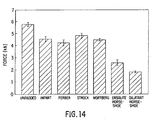
- Fig. 14 is a bar graph which displays the peak force applied to the femur during impact to each of the systems tested.
- the horseshoe shaped device constructed of Ensolite foam and possessing a maximum thickness of 25 mm lowered peak externally applied force by 33% and peak femoral force by 55%.
- the Impant device reduced peak externally applied force by 18% and peak femoral force by 21, a device in accordance with U.S. patent 4,926,883 reduced peak externally applied force by 14% and peak femoral force by 16%, and a device in accordance U.S. patent 4,807,301 reduced peak externally applied force by 17% and peak femoral force by 27%.
- the device in accordance with the present invention provides nearly a twofold greater reduction in peak externally applied force, and a threefold greater attenuation in peak femoral impac force.
- the results also suggest that when worn during a typical, fall on the hip, the horseshoe device in accordance with the present invention has the ability to lower femoral impact force to a value below the mean force required to fracture the elderly femur (2040 N).
- peak femoral force remained above twice the mean force required to fracture the elderly femur. It therefore appears that the present invention lowers the probability of suffering a hip fracture during a fall on the hip to a much greater extent than all tested prior art pads.
Abstract
Description
- The present invention relates generally to garments for bone fracture prevention, especially for the prevention of hip fracture during impact from a fall, and related methods.
- Fractures of the proximal femur are a major source of mortality and morbidity among the elderly. Approximately 250,000 hip fractures occur in the United States annually. Nearly 33 percent of women and more than 17 percent of men will experience a hip fracture if they live to age 90. Among patients who are functionally independent prior to a hip fracture, 15 to 25 percent remain in long-term care settings for more than a year afterward. Another 25 to 35 percent are dependent on others for their mobility. More than half of those that survive hip fracture never recover normal function. Moreover, the average mortality associated with hip fracture in elderly patients is approximately 20 percent in the first year.
- The public health impact of hip fractures is also staggering. Recent surveys in the United Kingdom have shown that at any one time about 50 percent of acute orthopedic beds are occupied by hip fracture patients. In the U.S., the average length of hospital stay for hip fracture patient is three weeks, longer than for any other diagnosis. The annual costs associated with the acute and chronic care of hip fracture patients in the United States is estimated to exceed $7 billion. The problem can only be expected to worsen with projected increases in the average age of the world population, leading some to suggest the possibility of a nearly three-fold rise in the total number of hip fractures by the middle of the next century.
- Over 90 percent of all hip fractures are caused by falls. However, the majority of falls in the elderly result in only minor injury, with one to three percent causing hip fracture. Surveys among elderly fallers have shown the following factors increase the risk for suffering a hip fracture in a fall (in order of importance): 1) impacting on the hip or side of the leg (which increases the risk of fracture by over 20-fold), 2) having a tall, slender body habitus, 3) falling with a high initial potential energy (which depends on both body mass and the height of the fall), and finally 4) possessing low bone density in the proximal femur. These results suggest the risk for hip fracture in a fall is dominated by the severity of the fall as opposed to the density and strength of the proximal femur. To reduce the incidence of hip fractures, hip fracture prevention strategies must therefore either reduce the incidence of falls, or protect the femur in the event of a fall. The former strategy may be accomplished by restricting mobility, although this carries associated medical risks and impairs personal autonomy and quality of life. It might also be accomplished through exercise programs in the elderly populations at greatest risk for falling, although no study to date has proven the effectiveness of such an approach. In any case, it seems unrealistic to expect the complete elimination of falls among the elderly, given the often multiple factors (cardiac, neural, musculoskeletal) and random causes of falls. It therefore appears that the most reliable method for reducing hip fracture incidence is to protect the femur during the impact stage of the fall. This essentially requires lowering the impact force applied to the femur to a value below its fracture threshold.
- Hip fracture refers to fracture of the proximal end of the femur, which is the strongest, heaviest, and longest bone in the body, accounting for approximately one-fourth of total body height. The proximal end of the femur consists of a head, neck, and greater and lesser trochanters. The neck of the femur connects the spherical head to the shaft. It is limited laterally by the greater trochanter, a large, somewhat rectangular lateral projection from the neck and shaft, which provides an insertion site for several muscles of the gluteal region. The greater trochanter lies laterally, just beneath a relatively thin layer of skin and adipose tissue (fat), and can be easily palpated on the lateral side of the thigh. Since it is the most lateral point of the hip region, the greater trochanter is the site which comes into contact with a hard surface when one lies on one's side, and the site where the majority of impact force is applied when one falls sideways onto the hip. Consequently, falls to the side resulting in impact to the greater trochanter carry a high risk for hip fracture.
- In contrast to the minimal amount of soft tissue covering the greater trochanter, a considerable quantity of soft tissue exists in the posterior gluteal (buttock) and anterior thigh regions adjacent to the greater trochanter. Upon impact to these regions, this soft tissue is able to absorb significant energy, and lower the impact forces applied to the underlying skeletal structures. Gluteal soft tissues include the gluteal maximus, medius, and minimus muscles, as well as the considerable layer of fat overlying the buttock. The most significant anterior thigh soft tissues are the guadriceps muscles, which include the three vastus muscles and the rectus femoris muscle.
- Experimentally, when the elderly cadaveric femur is loaded in a configuration simulating a fall on the hip, the average force required to fracture it is 2040 N [Lotz JC and Hayes WC, J Bone Joint Surg [Am], 72-A:689-700, 1990]. The corresponding average energy absorbed by the bone up to fracture is 25 J. At standing height, the potential energy of the body can be well over 20 times this amount. Furthermore, we have conducted experiments which suggest the force applied to the femur at impact from an average sideways fall to the hip is about 6 kN, over three times the mean fracture force (Robinovitch,SN, Hayes,WC, McMahon,TA, J Biomech Eng, 113: 366-374, 1991). It therefore appears that to avoid hip fracture during a fall, one or more of the following must occur: 1) direct impact to the lateral aspect of the hip must be avoided, 2) the impact site must extend outside the hip region, or 3) significant energy must be absorbed by alternative mechanisms such as contraction of the thigh muscles during descent, breaking the fall with an outstretched hand, or deformation of both the floor and the soft tissue overlying the impact sight.
- Similar to hip fracture, fracture of other bones such as the tibia, radius, and ulna occurs when the force applied to the bone exceeds that required to initiate fracture. Often such a situation arises when the impact energy is high, and contact occurs to a small area directly overlying the fracturing bony structure. In such circumstances, the impact energy cannot be absorbed and/or dissipated through a large area, and high local stresses are applied to the underlying bone.
- Several protective garments have been developed with the aim of preventing hip fractures. All of these devices attempt to reduce fracture incidence by reducing the impact force applied to the femur during a fall on the hip. Most incorporate an energy absorbing and/or dissipating material or structure placed directly over the greater trochanter and surrounding area (Ferber, U.S. patemt 4,807,301; Galton, U.S. patent 4,737,994; Kolb, U.S. patent 4,761,834; Kolsky, U.S. patent 5,034,998; Wortberg, U.S. patent 4,573,216). The major drawback of such devices is they cover the greater trochanter and proximal femoral diaphysis, and thus transmit load to these regions during impact to the hip. As described previously, these regions of the femur, and in particular the greater trochanter, extend furthest laterally of all bony components of the hip region, and are protected by a minimum of overlying soft tissue. They thus represent the regions of lowest compliance within the total protected area, and subsequently, during impact to the protective garment, the majority of impact force is transmitted to the femur.
- A further problem with protective devices which cover the greater trochanter is the compromise that designers face between device thickness and device rigidity. Device thickness largely determines wearer acceptability. The more slender the device, the more acceptable to the wearer. Device rigidity also affects wearer acceptability, since a soft, compliant device is more comfortable to the wearer than a hard, inflexible device. However, device rigidity also determines the amount of energy absorbed and magnitude of force produced by deformation of the device. A very compliant material, while generating low stress or pressure during compression, will also absorb little energy during deformation. Unless a device formed of such a material is several inches thick (and thus unacceptably thick to the wearer), the potential energy available in the fall will overwhelm the energy absorbing capacity of the material, causing it to completely compress or "bottom" before a significant portion of the energy of the fall is absorbed. In this bottomed state, the pad is unable to absorb further energy and the remaining energy must be absorbed by the soft tissues and the bone. To avoid bottoming of the pad under the high impact energies associated with falling, designers have selected relatively stiff elastic or viscoelastic pad materials. For example, U.S. patent 4,807,301 specifies the use of a viscoelastic foam called Sportcell selected to "not to bottom under the falling stress of normal body weight from a height of two feet". U.S. patent 4,737,994 describes a device for covering the hip region with an inflated air cushion which, if constructed to not bottom during impact, would become highly pressurized and stiff. Finally, U.S. patent 4,573,216 describes a fairly stiff silicon rubber pad designed to be worn over the greater trochanter. Such pad materials will absorb significant energy during deformation (or in the case of the inflatable pad, compression of the gas), allowing for a slender design. However, such deformation generates significant stresses or pressures in the pad material, resulting in high forces being transmitted to the underlying femur, and in particular the greater trochanter, which contains a minimal degree of overlying soft tissue.
- A second approach taken by inventors of hip fracture prevention devices, is to incorporate a rigid dome-shaped shield into the padding system (Strock, U.S. patent 4,641,641 and 4,926,883; Kummer, U.S. patent 5,062,433). In Strock's U.S. patent 4,641,641 and 4,926,883, this shield is designed to be centered over the greater trochanter, and upon impact, transfer force away from this region. However, several design features prevent this device from significantly lowering the impact force applied to the femur during a fall. First, only a small amount of force is required to initiate contact between the skin-side surface of the shield and the skin overlying the proximal diaphysis of the femur. Further compression of the pad will result in significant load transfer to the proximal diaphysis, which represents the least compliant portion of the contact region. Second, the small contact area formed between the edges of the rigid shield and the underlying skin favors the generation of high contact stresses, particularly over the relatively stiff proximal femoral diaphysis region which is just distal to the greater trochanter. No evidence exists supporting the notion that higher force is required to fracture the femur when this force is applied to the proximal diaphysis as opposed to the greater trochanter. Indeed, the increased moment arm of this force with respect to the femoral neck may result in femoral fracture at a lower magnitude of applied force.
- Other problems with the Strock system, or any system incorporating a rigid shield, include its inability to conform to changes in body shape under normal activities, thus restricting body motion and causing discomfort to the wearer. Furthermore, no method is provided for affixing the Strock pad to the body other than through the use of an adhesive to the skin, making these pads inappropriate for persons who would suffer skin problems due to long-term lack of ventilation to the skin.
- EP-A-0,099,010 discloses a protective pad for the protection of bones and organs of the human body from impacts or falls. The pad incorporates an incompressible viscous fluid integrally bonded to an outer elastic layer, thereby forming a direct energy absorbing structure.
- The present invention provides a protective pad for reducing the risk of bone fracture of a human or animal subject due to impact forces on a vulnerable region having a bone part near the skin surface when the vulnerable region is proximate to a soft tissue region lacking a bone part near the skin surface.
- The precharacterising part of Claim 1 is based on the disclosure of EP-A-0,099,010. The distinguishing features of the invention are set out in the characterising part of Claim 1. Claim 1 provides a protective pad for reducing the risk of bone fracture of a human or animal subject due to impact forces on a vulnerable region having a bone part near the skin surface, the vulnerable region being proximate to a soft tissue region lacking a bone part near the skin surface, the protective pad comprising a flexible enclosure containing padding material,
characterised in that the padding material includes shear-thickening material for shunting a substantial portion of the impact energy from the vulnerable region to the soft tissue region, where such energy may be safely dissipated. - The protective pad may be mounted so as to overlie the soft tissue region but not the vulnerable region. In one embodiment, the invention provides a hip pad possessing a thickness small enough to be compatible with wearer acceptability, that conforms to the shape of the body during everyday activities such as walking, sitting, and sleeping, and is thus comfortable to the wearer.
-
- Fig 1 is a perspective view of a protective garment in accordance with the present invention shown as worn on the hip of a human subject.
- Fig. 2 is a perspective view of an alternate protective garment in accordance with the present invention as worn on the hip of a human subject.
- Fig. 3 is a sectional view of a preferred embodiment of the present invention in which the flexible membrane of the garment is subdivided into several envelopes, each containing a shear-thickening material;
- Fig. 4 is a sectional view of an alternate preferred embodiment of the present invention in which a compliant and flexible sleeve surrounds the individual envelopes containing a shear-thickening material;
- Fig. 5 is a perspective view of a protective garment in accordance with the present invention in the form of shorts for women's or men's wear.
- Fig. 6 is a perspective view of a protective garment in accordance with the present invention which utilizes waist and thigh belts for affixing the device over the hip regions.
- Fig. 7 is a graph showing how the viscosity of the shear-thickening material contained within the present invention changes as a function of shear rate.
- Fig. 8 is a top view of a protective garment in accordance with the present invention for preventing injury to the ulna bone.
- Fig. 9 is a perspective view of a roll of envelopes containing shear-thickening material in accordance with an embodiment of the present invention for use in the customized design of protective garments.
- Fig. 10 is a perspective view of an alternate embodiment in accordance with the present invention in which is provided a flat array of envelopes containing shear-thickening material for use in the customized design of protective garments.
- Fig. 11 is a perspective view of a protective garment that has been customized in accordance with an embodiment of the present invention for use in preventing injury to the iliac spine.
- Fig. 12 is a side view of the impact pendulum and surrogate human pelvis used in testing the force attenuating capabilities of both the present invention and prior art hip protective devices.
- Fig. 13 is a line graph comparing total applied force and femoral force as functions of time when 120 Joules of impact energy is applied to a surrogate pelvis alone, and after affixing to the pelvis a device in accordance with an embodiment of the present invention, and also after employing a device in accordance with U.S. Pat. No. 4,573,216.
- Fig. 14 is a bar graph comparing peak total applied force and peak femoral force when 120 J of impact energy is applied to the surrogate pelvis alone, and after affixing to the surrogate pelvis a commercially available protective hip garment (Impant pad, developed by Dr. L. Proshek, Edina, MN), three different, previously patented hip protective devices (U.S. Pat. Nos. 4,926,883, 4,573,216, and 4,807,301), and two devices in accordance with embodiments of the present invention.
- The protective device in accordance with a preferred embodiment of the present invention comprises a horseshoe-shaped garment placed over the hip region so as to contact the skin adjacent, but not overlying, the greater trochanter and proximal diaphysis of the femur. In one embodiment, the garment has one or more envelopes made of a flexible material and containing within a substance which exhibits a marked increase in viscosity with increasing rate of shear deformation. This behavior, which causes the device to exhibit significantly greater flexibility and compliance at low rates of deformation, such as those occurring during everyday activities such as sitting and walking, than during the high rates of deformation surrounding impact, is known as "shear-thickening" or "dilatancy". The relative flexibility under everyday activity provides a degree of comfort to the wearer far exceeding previous designs which utilize a rigid dome-shaped shield or a relatively inflexible polymeric sheet. The ability of the pad to stiffen upon impact, combined with the horseshoe shape, allows for transmission of the energy of the body on impact into the soft tissues surrounding, but not overlying, the greater trochanter and proximal femoral diaphysis. Due to their bulk, these tissues are capable of absorbing and dissipating the impact energy without the production of large stresses. Since no part of the pad overlies the femur, force transmission to the femur is minimized, occurring at appreciable extent only after compression of the surrounding soft tissues causes the external surface of the pad to be in line with the external surface of the greater trochanter. However, the pad is constructed with a thickness sufficient to ensure this occurs, if at all, only in the most severe falls.
- Several possible mechanisms exist for affixing the garment over the hip regions. In one embodiment the protective device is fitted bilaterally into short pants, either in the form of cloth underwear or well fitted flexible shorts similar in appearance and function to those worn by bicyclists. In another embodiment, the protective device employs cloth straps which wrap around both the waist and thigh regions on the wearer, and possess a hook-and-pile fastener material such as that sold under the VELCRO trademark, to permit adjusting the position of the device to achieve optimal placement on the wearer. In another embodiment, the protective device is affixed to the hip regions of the wearer through the use of adhesive strips on the inner surface of the device permitting it to secured to the skin in the optimal position over the hip region.
- It is believed that the invention provides an arrangement that is more effective at reducing the force applied to the femur during impact on the hip from a fall and more comfortable to wear than prior art pads.
- Fig. 1 shows a perspective view of a protective garment embodied in accordance with the present invention and worn on the hip of a human subject. The
garment 2 has a number of flexible andcompliant envelopes 4 each containing a shear-thickening or dilatant material. Thecompliant envelopes 4 are separated by bonds, and are arranged to form an inverted "U" or horseshoe shape approximately centered about themidpoint 8 of the greater trochanter of the femur. The anterior portion of thedevice 3 is connected to the posterior portion of the device 7 a flexible but relativelynon-compliant strip 6, which may be made of cloth. Thiscloth 6 is secured to the compliant envelopes on the superior internal border of thehorseshoe 13, the anterior internal border of thehorseshoe 16, and the posterior internal border of thehorseshoe 15 by means of abond 9. - In the embodiment of the invention illustrated in Fig. 1, the horizontal distance between the posterior internal border of the
horseshoe 15 and the anterior internal border of thehorseshoe 16 is relatively constant over the length of the pad at a value of approximately 40 mm. However, alternative embodiments may exist involving devices where this width is constant at a value between 30 and 70 mm, or devices involving variations in this width along the length of the pad between 30 and 70 mm. The device is so positioned that, along ahorizontal line 8 passing through the greater trochanter, the posterior internal border of thehorseshoe 15 and the anterior internal border of thehorseshoe 16 are roughly an equal horizontal distance from themidpoint 8 of the greater trochanter. Similarly, along any horizontal line below thegreater trochanter midpoint 8 and passing through theprotective garment 2 and theaxis 10 of the proximal femoral diaphysis, the anterior internal border of thehorseshoe 16 and the posterior internal border of thehorseshoe 15 are roughly an equal horizontal distance from the axis X-X of the proximal femoral diaphysis. - Again referring to Fig. 1, the superior internal border of the
horseshoe 13 is located roughly 20 mm above the midpoint of the greater trochanter of thefemur 8. However, alternative embodiments of the device may exist where the location of the superior internal border of thehorseshoe 13 is constant at a value between 10-40 mm above the midpoint of thegreater trochanter 8. Further alternative embodiments may exist where the location of the superior internal border of thehorseshoe 13 varies between 10-40 mm above the midpoint of the greater trochanter. - In the embodiment of the invention shown in Fig. 1, the
external border 14 of thedevice 2 extends inferiorly to approximately 10 cm below the midpoint of the greater trochanter, posteriorly (at its greatest extent) to approximately 10 cm horizontal to thegreater trochanter midpoint 8, superiorly to approximately 2 cm below thelocation 12 of the superior iliac spine, and anteriorly to approximately 7 cm horizontal to the greater trochanter midpoint. - Alternative embodiments of the device may exist where the
external border 14 of thedevice 2 extends a farther or lesser amount than that shown in Fig. 1. For example, Fig. 2 shows an alternative embodiment of a device in accordance with the present invention. In this embodiment, the dimensions and location of the internal open portion of the horseshoe are similar to that described for Fig. 1. However, the number ofenvelopes 4 containing the shear-thickeningmaterial 22 has been reduced to nine, each roughly forming the shape of a square with surface area of approximately 4 cm2. The surface area of the device may also extend well beyond that shown and described for Fig. 1, being limited inferiorly only by the knee, posteriorly by the anal fold or crease between the buttocks, anteriorly by the midpoint of the anterior aspect of the thigh, and superiorly by a point about 10 mm below the superior iliac spine. - In the embodiment of the device shown in Fig. 1 and Fig. 2, the thickness of
protective device 2 is constant at approximately 30 mm. However, alternative embodiments ofprotective device 2 may involve a constant thickness throughout the device between 10-50 mm, or variation in thickness throughout the device between 10-50 mm. - Fig. 3 is a sectional view of one preferred embodiment of the present invention in which a flexible and
compliant membrane enclosure 18 is subdivided into several anddistinct envelopes 4, each containing a shear thickening ordilatant material 22. In this embodiment,membrane 18 is made of an elastomeric polymer such as polyurethane, PVC, latex rubber, or pure gum rubber, having a constant thickness between 0.1-1 mm. Abond 5 exists between contacting surfaces ofenvelopes 4 adjacent to one another. Thisbond 5 may be created through various means, including application of an adhesive or a process whereby a chemical reaction or the application of heat or electrical current results in bonding of the membrane material. Eachenvelope 4 is filled with shear-thickeningmaterial 22 at a pressure which causes a small degree of stretch within the membrane material. - Still referring to Fig. 3, shear-thickening
material 22 includes a suspension of relatively uniform-sized solid particles 19 (size greatly exaggerated in Fig.3) in aviscous fluid 21. The properties ofsolid particles 19 andviscous fluid 21 may vary considerably between different embodiments of the invention. For example, the diameter ofparticles 19 may vary between 0.1-100 micrometers. The viscosity of the fluid 21 may vary between 1-1,000,000 cP. The ratio of the volume ofsolid particles 19 to total volume of the material 22 ranges between 20-70 percent. - In one embodiment of the invention,
fluid 21 is water andparticles 19 are untreated or modified starch granules, where the starch may be corn starch, potato starch, or any plant starch. In another embodiment,particles 19 are plant Starch granules, andfluid 21 is a fluid other than pure water. In yet another embodiment,particles 19 are spheres made of a polymer such as polyurethane, polystyrene, or polyvinylchloride and of size 0.1-500 micrometers, and the fluid 21 is water. In yet another embodiment,particles 19 are spheres made of a polymer such as polyurethane, polystyrene, or polyvinylchloride and of size 0.1-500 micrometers, and the fluid 21 is an oil such as silicon or mineral oil having a viscosity between 10 and 1000000 cP. - It is therefore apparent that shear-thickening
material 22 may be formed from a wide variety of particles and fluids. However, its essential feature is an increase in viscosity as a function of shear rate. In particular, the viscosity ofmaterial 22 increases dramatically at a relatively well-defined value known as the critical shear rate. This behavior is shown schematically in Fig. 7, where the logarithm of the shear rate γ is shown on the horizontal axis and the logarithm of viscosity η is shown on the vertical axis. The sudden increase in viscosity at the critical shear rate causes a corresponding increase in the shear stress produced in the material (shear stress is equal to the shear rate multiplied by the viscosity), a measure of its resistance to deformation. In a preferred embodiment of the present invention, the critical shear rate of shear-thickeningmaterial 22 is set between 1-100 5-1, and typically between 5-30 s-1. - In an alternative embodiment of the present invention, the
protective device 2 of Figs. 1 and 2 may be formed into the shape of a horseshoe, and instead of incorporating shear-thickening material, the device is made of a single continuous or several and distinct adjacent members of a elastic or viscoelastic material, such as that sold under the tradename Ensolite. - In yet another alternative embodiment, one or more thin rigid members, possibly formed of a polymeric material such as polyurethane, are affixed to the external surface of
protective pad 2, and form a shell which aids in transmitting loads throughout the device. - Fig. 4 is a sectional view of an alternate preferred embodiment of the present invention in which flexible and
compliant membrane enclosure 18 is subdivided into several anddistinct envelopes 4, each containing shear thickening ordilatant material 22. In this embodiment,envelopes 4 are not bonded together, but enclosed between a compliant and flexibleinternal sleeve 25 and a compliant and flexibleexternal sleeve 26. In a preferred embodiment,internal sleeve 25 andexternal sleeve 26 are both constructed of an elastomeric material friendly to the skin such as sold under the SPANDEX trademark. This material preferably should not limit flexibility of the entire pad; accordingly it is sometimes desirable that the product of thickness and elastic modulus for this material be equal to or less than that described above formembrane enclosure 18. In the gap betweenadjacent envelopes 4, abond 23 exists betweeninternal sleeve 25 andexternal sleeve 26, wherebond 23 is formed by an adhesive, stitching, or chemical reaction, or the application of heat or electrical current. - Various methods exist for affixing the hip protective device to the wearer. In one preferred embodiment shown in Fig. 5A, the
pad 2 is integrated into a pair ofshorts 28 for women's or men's wear. Fig. 5B, shows a cross section of the embodiment of Fig. 5A taken through the plane B-B in Fig. 5A.Shorts 28 are formed of an inner compliant andflexible material 31 and a similar outer compliant andflexible material 30. This material may be SPANDEX or a similar material. The shorts are sized to fit snugly around the wearer, with bothinner material 31 andouter material 30 in a state of stretch during normal wear. Hipprotective device 2 is secured intoshorts 28 by abond 29 around the parimeter of thepad 2. As in other embodiments, the pad hasenvelopes 4 containing withinmembrane 18 shear-thickeningmaterial 22. - Several different embodiments exist with respect to the arrangement of
short pants 28 and the integration ofprotective device 2 within the pants. In one potential embodiment,bond 29 is permanent and formed of stitching or an adhesive material, while in another embodiment all or a portion ofbond 29 is easily broken and reformed, as would be provided if the bond was formed of a hook-and-pile material such as that sold under the name VELCRO. This latter embodiment allows easy insertion and removal ofprotective device 2 intoshort pants 28 to facilitate easy cleaning ofshort pants 28 or replacement ofprotective device 28, if required. - Furthermore, in one embodiment
short pants 28 are continuous, while in another embodimentshort pants 28 are crotchless, thus facilitating use by individuals suffering from incontinence. - Fig. 6 is a perspective view of an alternate method of affixing over the hip region a protective garment in accordance with the present invention. In this arrangement, a confirmed
waist belt 44 having right and left portions, mounts a pair ofprotective pads pile strips 45 and posteriorly located, mating hook-and-pile strips 46. Similarly, conformedthigh belts 38 are used to affix the bottom portions of theprotectors protective pads vertical strips protective pads protective pads - Another method for affixing the device to the hip involves securing an adhesive layer over the internal surface of the pad which opposes the skin. This adhesive layer bonds to both the pad and the skin, and allows precise placement of the protective device over the hip. This method for affixing the device may be particularly suited to those persons at greatest risk for suffering falls and thus in need of constant protection. Depending on the properties of the adhesive, the device may be mounted for a number of days or weeks, while being removed periodically to allow washing of the underlying skin.
- The present invention can also be applied towards prevention of fractures of bones other than the femur, such as the radius, ulna, and tibia. For example, Fig. 8 displays a
protective device 58 embodied in accordance with the present invention and designed to protect against fracture or injury of the ulna in sporting activities such as football, where protective devices of this type are currently worn, or during any other activities where such protection is desired. Typically the device may be positioned between the ulna'shead 62 and thetip 60 of the ulna's olecranon process. The device includes a laterally and medically located strips 64 and 68 respectively of flexible envelopes containing shear-thickening material. Arigid shell 68 formed of a polymeric material is adhered by an adhesive so as overlie the external surface ofstrips shell 68 and the skin overlying the ulna. As a result of this construction, upon impact to theshell 68, the energy of impact is spread away from the ulna and into the softtissues underlying strips sleeve 70 formed of a flexible, elastic material is adhered to shell 68 by means of a glue or adhesive, and aids in maintaining proper positioning ofprotective device 58 over the ulna. - In another embodiment of the present invention, designed to serve as shin guards for sports such as soccer, an arrangement similar to that shown in Fig. 8 for protecting the ulna, here provided for the tibia, and is thus worn over the anterior shin. In this arrangement, two strips of envelopes containing shear-thickening material are placed in parallel with the tibia on both medial and lateral sides. As in the case for the ulna, a rigid shell is adhered over these strips so that a gap exists between the shell and the underlying tibia.
- In a further embodiment of the present invention,
envelopes 4 containing shear-thickeningmaterial 22 are made available for the customized design of protective devices, either for the general prevention of injuries during sporting or other activities or for preventing further injury or pain from impact to a previously injured and therefore sensitive location. Figs. 9 and 10 show two possible arrangements in which this product might be supplied. Fig. 9 shows aroll 72 ofenvelopes 4, each containing shear thickening material. Dual-sidedadhesive tape 78 is adhered to both the front and back sides of the envelopes. A layer of waxpaper or similar matter is used to cover at least the outword facing side ofadhesive tape 78. Scissors can be used to cut along ajunction 76 between adjacent envelopes, and thus produce a strip ofenvelopes 4 of desired length. After then removing the waxpaper layers covering theadhesive tape 78,envelopes 4 can be mounted directly to the skin and a rigid shell can be mounted overenvelopes 4. If required, further adhesive tape, elastic straps,or some other means may be utilized to supplementadhesive tape 78 in securingenvelopes 4 to the desired location on the body. - Fig. 10 displays an alternative method by which
envelopes 4 may be supplied, including aflat sheet 80 ofenvelopes 4 arranged in close proximity to one another. Again, scissors may be used to cut alongjunctions 76 to produce a protective device of the desired shape. - Fig. 11 shows one of the several possible customized protective devices capable of being formed from the embodiments of Figs. 9 and 10. In this case, a device has been constructed to protect against further injury or pain from impact to the
iliac crest 88, which is often injured in sporting activities such as football, basketball, or hockey (the injury is often referred to as a "hip pointer"). The device here includes asuperior strip 82 of envelopes containing shear-thickening material, and aninferior strip 84 of envelopes containing shear-thickening material. Arigid shell 86 is adhered over the external surface ofstrips iliac crest 88. Since shear-thickening material is fluid under low rates of loading, a continuous contact area is formed between the underlying skin and strips 82 and 84. Upon impact to the rigid shell, shear-thickening material stiffens, and shunts the impact energy into the softtissues underlying strips iliac crest region 88. - The effectiveness of a hip fracture prevention garment depends on the ability of the garment to lower the peak force applied to the femur in a fall to a value significantly below the mean force required to fracture the elderly femur (2040 N). In order to realistically assess the attenuation in femoral impact force provided by the device, it must be tested under conditions which simulate the interaction between the device and the underlying skeletal and soft tissues. A common fault in estimating the force attenuation provided by hip protective devices is to disregard the role of the soft tissues between the femur and the protective device. For example, Ferber, in U.S. patent 4,807,301, describes testing the force attenuating capacity of the energy-absorbing material to be placed over the greater trochanter in his preferred embodiment by dropping a steel weight onto the material from a 24-inch height. He then appears to assume the same degree of force attenuation is provided when the pad is worn over the hip in a fall. However, this will result in overestimation of the actual force attenuation provided by the protective device during a fall on the hip, since a steel weight is many times more rigid than the human hip. To obtain a reasonable estimate of this attenuation, one requires knowledge and incorporation of the compliance of the unpadded hip. Wortberg, in his U.S. patent 4,573,216, appears to account for the compliance of the femur, cartilage of the hip joint, and the overlying skin in estimating the force attenuation provided by the protective device. However, he does not account for the compliances of the fat and muscle overlying the trochanteric region, or the compliance of the pelvis.
- To evaluate and compare the protective ability of the present invention with that provided by prior art protective devices, we have measured the impact force attenuation provided by several different hip protective devices. These included the following prior art hip protective devices:
- (1) a commercially available device formed of an energy-absorbent foam and rigid external shell, designed to cover the greater trochanter and surrounding area, and having a maximum thickness of approximately 32 mm ("Impant" pad, Dr. L. Proshek, Edina, MN); (2) a protective appliance constructed by Strock in accordance with his U.S. patent 4,926,883 and of maximum thickness 35 mm; (3) a protective appliance constructed by Ferber in accordance with his U.S. patent 4,926,883 and of
maximum thickness 11 mm; (4) a protective appliance constructed by Wortberg in accordance with his U.S. patent 4,926,883 and ofmaximum thickness 38 mm. In addition, the following embodiments of the present invention were tested: (1) a horseshoe-shaped device constructed of a viscoelastic foam sold under the trademark Ensolite, and having a maximum thickness of 25 mm; (2) a horseshoe-shaped device constructed of a shear-thickening corn starch-water mixture, and having a maximum thickness of 35 mm; and (3) a horseshoe-shaped device constructed of a shear-thickening corn starch-water mixture, and having a maximum thickness of 49 mm. These tests have provided data regarding the ability of these pads to attenuate femoral impact force, and thus reduce the probability of hip fracture occurrence during a fall on the hip. The results of these tests indicate that, while each strategy accomplishes attenuation of femoral impact force, only a device in accordance with the present invention reduces this force to a value below that required to fracture the elderly femur. - The testing system is shown in Fig. 12, and includes an impact pendulum (including a
mass 121,arm 122,pivot 123, and head 128) andsurrogate pelvis 124 designed to match the typical female pelvis in surface anatomy, local soft tissue stiffness, and pelvic compliance. Thesurrogate pelvis 124 includes asurrogate femur 125 surrounded byfoam 126 to simulate behaviour of soft tissue. Aload cell 127 producing a signal to measure force on thefemur 125, and apelvic spring 128 simulates the effect of pelvic compliance. The surrogate pelvis allowed us to evaluate pad performance based on the combined response of the hip pad and the underlying skeletal and soft tissue structures. The polyurethane foams forming the soft tissues of the surrogate were selected to match the regional variation in soft tissue stiffness exhibited by females during indentation tests over the trochanteric, gluteal, and anterior thigh regions. Mean values of stiffness at 60 N (which ranged from 35±13.9 kN/m over the greater trochanter to 8.5±2.9 kN/m over the posteriolateral buttock) were matched on average to within 35% during tests at corresponding locations on the surrogate. Pelvic compliance was simulated by neoprene springs 128, providing the entire unit with an effective stiffness of 83 kN/m, within 18% of that measured in females undergoing simulated falls on the hip (Robinovitch, S.N., Hayes, W.C., McMahon, T.A., J Biomech Eng, 113: 366-374, 1991). In all experiments, the pendulum head was directed to impact the lateral aspect of the greater trochanter. Total externally applied force was measured by aload cell 129 on the pendulum, while the force delivered through the soft tissues to the hip was measured with theload cell 127 mounted on the femur. Pendulum impact velocity was 2.6 m/s, similar to the average hip impact velocity measured in human volunteers falling on their hip. Pendulum mass was 35 kg, matching the average effective mass of the body during impact to the hip [Robinovitch, S.N., Hayes, W.C., McMahon, T.A., J Biomech Eng, 113: 366-374, 1991]. The kinetic energy of the pendulum at the moment of impact was therefore 120 Joules. - Fig. 13 is a line graph of experimental results. Force is plotted on the vertical axis of the graph, and time is plotted on the horizontal axis of the graph. Both total externally applied force and total femoral force are shown, the former in dotted lines and the latter in solid lines. For clarity, the results from only three impact tests are shown. These include: (1) impact to the unpadded surrogate pelvis (shown by curves 131); (2) impact to the surrogate pelvis after affixing to the skin of the pelvis the horseshoe shaped device in accordance with the present invention, incorporating a shear-thickening corn starch-water material, and possessing a maximum thickness of 35 mm (shown by curves 132); and (3) impact to the surrogate pelvis after affixing to the skin of the pelvis the device in accordance with Wortberg's U.S. pattent 4,573,216 and possessing a maximum thickness of 38 mm. Note in the unpadded case, peak total external applied force was 5960 N and peak femoral force was 5770 N. In each set of curves, the total load is shown by a dashed line, and the femural load is shown by a solid line. The Wortberg pad (which provides a degree of force attenuation typical of all prior art pads tested), reduces peak externally applied force by 20% to 4770 N and peak femoral force by 22% to 4500 N. In comparison, the horseshoe pad of 35 mm maximum thickness reduces peak externally applied force by 39% to 3590 N, while reducing peak femoral force by 68% to 1840 N. Not shown are the results for impacts to the horseshoe pad of 49 mm maximum thickness, which reduces peak externally applied force by 36% to 3800 N, and peak femoral force by 88% to 700 N.
- Fig. 14 is a bar graph which displays the peak force applied to the femur during impact to each of the systems tested. Note the horseshoe shaped device constructed of Ensolite foam and possessing a maximum thickness of 25 mm lowered peak externally applied force by 33% and peak femoral force by 55%. In comparison, the Impant device reduced peak externally applied force by 18% and peak femoral force by 21, a device in accordance with U.S. patent 4,926,883 reduced peak externally applied force by 14% and peak femoral force by 16%, and a device in accordance U.S. patent 4,807,301 reduced peak externally applied force by 17% and peak femoral force by 27%.
- The results of these tests show that, when compared to the next most effective prior art hip protective device, the device in accordance with the present invention provides nearly a twofold greater reduction in peak externally applied force, and a threefold greater attenuation in peak femoral impac force. The results also suggest that when worn during a typical, fall on the hip, the horseshoe device in accordance with the present invention has the ability to lower femoral impact force to a value below the mean force required to fracture the elderly femur (2040 N). Conversely, with all prior art devices tested, peak femoral force remained above twice the mean force required to fracture the elderly femur. It therefore appears that the present invention lowers the probability of suffering a hip fracture during a fall on the hip to a much greater extent than all tested prior art pads.
Claims (11)
- A garment for reducing the risk of bone fracture of a human or animal subject due to impact forces on a greater trochanter disposed in a hum of the human or animal subject, said greater trochanter being at the end of a femur and wherein the hip has a soft tissue region proximate to the greater trochanter and the femur lacking a bone part near the skin surface, the garment including a pad (14) and mounting means (28;38,44,78) for removably mounting the pad on the subject, the garment being characterised in that:-the pad is an energy shunting pad (14) including two arms (3,7) defining an exposed interior area between the two arms, the interior area coinciding generally with the greater trochanter and the femur when the garment is mounted on the subject; andthe mounting means (28;38,44,78) removably mounts the energy shunting pad on the subject with the two arms proximate to opposing sides of the femur so that a substantial portion of impact energy directed at the hip of the subject is shunted from the greater trochanter to the soft tissue region where such energy may be safely dissipated.
- A garment according to Claim 1 wherein the energy shunting pad (14) is in the shape of a horseshoe.
- A garment according to Claims 1 or 2 wherein at the exposed interior area between the two arms (3,7) the distance between the two arms is between 30 mm and 70 mm.
- A garment according to Claims 1, 2 or 3 further comprising an envelope (4) of an elastomeric material in which is disposed energy shunting material.
- A garment according to any preceding claim further comprising a plurality of adjacent envelopes (4), each envelope containing a portion of energy shunting material.
- A garment according to any preceding claim wherein the mounting means (28;38,44,78) mounts the energy shunting pad (14) on the subject so as to overlie the soft tissue region but not the greater trochanter and the femur.
- A garment according to any preceding claim wherein the mounting means includes a pair of short pants (28) in which is disposed the energy shunting pad (14).
- A garment according to any of Claims 1 to 6 wherein the mounting means includes a plurality of belts (44,38) coupled to the energy shunting pad (14).
- A garment according to any of Claims 1 to 6 wherein the mounting means includes adhesive means (78) for adhering the pad to the body of a subject.
- A method of reducing risk of bone injury due to impact forces on a greater trochanter disposed in a hip of a human or animal subject, the method comprising mounting a garment defined by any preceding claim on the subject so that the interior area coincides generally with the greater trochanter and femur so that a substantial portion of impact energy directed at the hop is shunted from the greater trochanter to the soft tissue region where such energy may be safely dissipated.
- A method of Claim 10 wherein the step of mounting is performed such that none of the energy shunting padding overlies the femur.
Applications Claiming Priority (3)
| Application Number | Priority Date | Filing Date | Title |
|---|---|---|---|
| US07/979,154 US5599290A (en) | 1992-11-20 | 1992-11-20 | Bone fracture prevention garment and method |
| US979154 | 1992-11-20 | ||
| EP94902297A EP0669811B1 (en) | 1992-11-20 | 1993-11-18 | Bone fracture prevention garment and method |
Related Parent Applications (2)
| Application Number | Title | Priority Date | Filing Date |
|---|---|---|---|
| EP94902297A Division EP0669811B1 (en) | 1992-11-20 | 1993-11-18 | Bone fracture prevention garment and method |
| EP94902297.4 Division | 1994-06-09 |
Publications (3)
| Publication Number | Publication Date |
|---|---|
| EP0797933A2 true EP0797933A2 (en) | 1997-10-01 |
| EP0797933A3 EP0797933A3 (en) | 1997-12-17 |
| EP0797933B1 EP0797933B1 (en) | 2000-10-25 |
Family
ID=25526739
Family Applications (2)
| Application Number | Title | Priority Date | Filing Date |
|---|---|---|---|
| EP94902297A Expired - Lifetime EP0669811B1 (en) | 1992-11-20 | 1993-11-18 | Bone fracture prevention garment and method |
| EP97201694A Expired - Lifetime EP0797933B1 (en) | 1992-11-20 | 1993-11-18 | Bone fracture prevention garment and method |
Family Applications Before (1)
| Application Number | Title | Priority Date | Filing Date |
|---|---|---|---|
| EP94902297A Expired - Lifetime EP0669811B1 (en) | 1992-11-20 | 1993-11-18 | Bone fracture prevention garment and method |
Country Status (10)
| Country | Link |
|---|---|
| US (2) | US5599290A (en) |
| EP (2) | EP0669811B1 (en) |
| JP (1) | JP3608621B2 (en) |
| AT (2) | ATE197118T1 (en) |
| AU (2) | AU679197B2 (en) |
| CA (1) | CA2147878C (en) |
| DE (2) | DE69316390T2 (en) |
| DK (2) | DK0797933T3 (en) |
| ES (2) | ES2112515T3 (en) |
| WO (1) | WO1994012066A1 (en) |
Cited By (5)
| Publication number | Priority date | Publication date | Assignee | Title |
|---|---|---|---|---|
| FR2797153A1 (en) * | 1999-08-06 | 2001-02-09 | Inst Nat Rech Securite | Knee protector esp for persons working mainly in kneeling position has miniature moulded pads on both sides of flexible membrane |
| WO2001087432A3 (en) * | 2000-05-19 | 2002-03-28 | Armadillo Sports Design Ltd | A protective appliance |
| WO2004012934A1 (en) * | 2002-08-01 | 2004-02-12 | E.I. Du Pont De Nemours And Company | Protective laminate structure |
| WO2006029486A1 (en) * | 2004-09-16 | 2006-03-23 | Philippe Kriwin | Garment |
| US9402779B2 (en) | 2013-03-11 | 2016-08-02 | Covidien Lp | Compression garment with perspiration relief |
Families Citing this family (97)
| Publication number | Priority date | Publication date | Assignee | Title |
|---|---|---|---|---|
| US5712011A (en) * | 1995-07-27 | 1998-01-27 | Beth Israel Deaconess Medical Center, Inc. | Tug-resistant link |
| US6241930B1 (en) | 1995-11-30 | 2001-06-05 | Ubertech Texas, Inc. | Method of constructing a garment with a graphical design thereon |
| US6193914B1 (en) | 1995-11-30 | 2001-02-27 | Ubertech Texas, Inc. | Molding thermosetting polymers onto substrates |
| US5914082A (en) | 1995-11-30 | 1999-06-22 | Harrison; Donald G. | Method and apparatus for molding thermosetting polymers onto substrates |
| US5939004A (en) | 1995-11-30 | 1999-08-17 | Harrison; Donald G. | Molding thermosetting polymers onto substrates |
| US5928593A (en) | 1995-11-30 | 1999-07-27 | Harrison; Donald G. | Method and apparatus for molding thermosetting polymers onto substrates |
| US6139787A (en) | 1996-10-24 | 2000-10-31 | Ubertech Texas, Inc. | Method for applying molded silicone design elements onto substrates |
| DK0962156T3 (en) * | 1996-12-20 | 2007-03-26 | Gunze Kk | waist protection |
| US5918310A (en) * | 1997-05-09 | 1999-07-06 | Farahany; Amir H. | Body protective garment |
| US5920915A (en) * | 1998-09-22 | 1999-07-13 | Brock Usa, Llc | Protective padding for sports gear |
| US6032300A (en) * | 1998-09-22 | 2000-03-07 | Brock Usa, Llc | Protective padding for sports gear |
| GB9911056D0 (en) * | 1999-05-12 | 1999-07-14 | Plant Daniel J | Active Protection |
| US6195809B1 (en) * | 1999-12-13 | 2001-03-06 | Prevent Products, Inc. | Hip-pad for protection of greater trochanter |
| GB0000227D0 (en) * | 2000-01-07 | 2000-03-01 | Univ Leicester | Impact absorbing device |
| US7662468B2 (en) | 2000-10-06 | 2010-02-16 | Brock Usa, Llc | Composite materials made from pretreated, adhesive coated beads |
| US7000616B2 (en) * | 2000-10-19 | 2006-02-21 | Diaz R Gary | Wound care suspension system |
| US6892734B1 (en) * | 2000-10-19 | 2005-05-17 | Thomas R. Schleicher | Wound care suspension system |
| US7402147B1 (en) | 2000-11-17 | 2008-07-22 | Susan Davis Allen | Body limb movement limiter |
| ATE468769T1 (en) * | 2001-09-13 | 2010-06-15 | Daniel James Plant | FLEXIBLE ENERGY ABSORBING MATERIAL AND PRODUCTION PROCESS |
| US7609512B2 (en) | 2001-11-19 | 2009-10-27 | Otter Products, Llc | Protective enclosure for electronic device |
| GB0130834D0 (en) * | 2001-12-22 | 2002-02-06 | Design Blue Ltd | Energy absorbing material |
| US6660882B2 (en) * | 2002-03-18 | 2003-12-09 | Council Of Scientific And Industrial Research | Process for the preparation of 2-Methyl-2-propene-1-sulfonic acid, sodium salt |
| US20060026864A1 (en) * | 2002-05-08 | 2006-02-09 | Liquicell Technologies, Inc. | Ultra-thin liquid-filled insole interface |
| US6859948B2 (en) * | 2002-09-16 | 2005-03-01 | Michael Melts | Hip protector system |
| US6786508B2 (en) | 2002-09-30 | 2004-09-07 | Lear Corporation | Occupant protection apparatus for a vehicle |
| US20040168245A1 (en) * | 2002-10-18 | 2004-09-02 | Goodwin Edward L. | Washable, protective hip pad construction |
| US8091692B2 (en) * | 2003-03-03 | 2012-01-10 | Massachusetts Institute Of Technology | Fluid-filled cellular solids for controlled |
| FR2852790B1 (en) * | 2003-03-26 | 2005-09-16 | Emeric Daniau | INDIVIDUAL PROTECTION SYSTEM AGAINST SHOCKS, IN PARTICULAR VESTABLE BALL BARRIERS |
| SE525107C2 (en) * | 2003-04-11 | 2004-11-30 | Otto Bock Skandinavia Ab | Joint protection and protective pads therefore |
| US20050089678A1 (en) * | 2003-08-20 | 2005-04-28 | Mead Steven R. | Multi-layered floorig composite including an acoustic underlayment |
| US7425171B2 (en) * | 2004-02-13 | 2008-09-16 | Kathy Maupin | Post surgical binder |
| JP2005281936A (en) * | 2004-03-31 | 2005-10-13 | Wacoal Corp | Waist-protecting pad |
| GB0414734D0 (en) * | 2004-07-01 | 2004-08-04 | Newcastle Upon Tyne Hospitals | Hip protector |
| US20060014008A1 (en) * | 2004-07-15 | 2006-01-19 | Akron General Medical Center | Force dispersion pad |
| US20060049950A1 (en) * | 2004-08-13 | 2006-03-09 | Lockhart Thurman E | Fall-sensing systems, hip protector systems, and other protective systems |
| US7823219B2 (en) * | 2004-09-27 | 2010-11-02 | Angiosome, Inc. | Decubitus ulcer prevention and treatment |
| US7941867B2 (en) * | 2004-11-19 | 2011-05-17 | Olson Keith D | Protective device |
| DK200402020A (en) * | 2004-12-29 | 2006-06-30 | Tytex As | Clothing, protective device and method for reducing the risk of fracture |
| FR2883469B1 (en) * | 2005-03-23 | 2008-02-01 | Eric Georges Lucien Gilli | NECESSARY AND METHOD FOR PROTECTING DRESSINGS AND / OR WOUNDED SKIN AREAS OF THE BODY |
| US7073202B1 (en) | 2005-09-22 | 2006-07-11 | Geary John A | Wrist protector |
| GB0519710D0 (en) * | 2005-09-28 | 2005-11-02 | Progressive Sports Technologies Ltd | Protective lower leg garment |
| JP2007131990A (en) * | 2005-10-11 | 2007-05-31 | Sumitomo Rubber Ind Ltd | Human body protecting tool |
| MA28760B1 (en) * | 2006-01-03 | 2007-08-01 | Rxr Protect | INFLATABLE PROTECTION VALVE |
| US20070157356A1 (en) * | 2006-01-07 | 2007-07-12 | Jigang Jin | Ski pants |
| US7941875B1 (en) * | 2006-02-27 | 2011-05-17 | Brown Medical Industries | Trabecular matrix like protectors and method |
| US7941876B2 (en) * | 2006-03-18 | 2011-05-17 | Robert C Ferber | Apparatus, method and system for protecting hips from fracture, and for providing immediate response to hip fracture events |
| FR2903579B1 (en) * | 2006-07-17 | 2008-09-26 | Pjdo Soc Par Actions Simplifie | EXTERNAL PROTECTION COVER, PARTICULARLY INTENDED TO BE INTEGRATED WITHIN A PROTECTIVE COVER OR A PROTECTIVE GARMENT INCORPORATING SUCH A HULL |
| US7784116B2 (en) * | 2006-07-27 | 2010-08-31 | Reebok International Ltd. | Padded garment |
| GB0617452D0 (en) * | 2006-09-05 | 2006-10-18 | Regent Medical Ltd | Surgical and medical garments and materials incorporating shear thickening fluids |
| JP2007107176A (en) * | 2006-10-16 | 2007-04-26 | Nisshin Kikaku:Kk | Sportswear |
| US20080127394A1 (en) * | 2006-11-27 | 2008-06-05 | Tammany Paige Atkinson | Protective garments |
| US8087101B2 (en) * | 2007-01-19 | 2012-01-03 | James Riddell Ferguson | Impact shock absorbing material |
| US8732869B2 (en) | 2008-06-13 | 2014-05-27 | Comfihips, Llc | Compliant impact protection pad |
| US8151376B2 (en) * | 2008-06-13 | 2012-04-10 | ConfiHips, LLC | Compliant impact protection pad |
| GB2463712A (en) * | 2008-07-11 | 2010-03-31 | Tech21 Licensing Ltd | Casing For Protecting Portable Devices |
| US8898820B2 (en) * | 2008-08-01 | 2014-12-02 | Nike, Inc. | Layered apparel with attachable and detachable elements |
| NZ580201A (en) * | 2009-10-06 | 2010-10-29 | Delloch Ltd | A protective device for protecting the hip area including an impact sensor and alarm |
| US20110155141A1 (en) * | 2009-12-28 | 2011-06-30 | Sawyer Lawrence H | Wearable Article That Stiffens Upon Sudden Force |
| WO2011091361A1 (en) | 2010-01-22 | 2011-07-28 | Under Armour, Inc. | Padding arrangement and method of making the same |
| US9427347B2 (en) | 2010-04-06 | 2016-08-30 | Hosso, Inc. | Limb protection device |
| US9044306B2 (en) | 2010-04-06 | 2015-06-02 | Hosso, Inc. | Limb protection device |
| US10314680B2 (en) | 2010-04-06 | 2019-06-11 | Horsepower Technologies Inc. | Limb protection device |
| US8894594B2 (en) | 2010-04-06 | 2014-11-25 | Hosso, Inc. | Limb protection device |
| US8679047B2 (en) | 2010-05-21 | 2014-03-25 | Presidium Athletics LLC | Impact resistant, torsion-reducing protective athletic gear using shear thickening fluid |
| AU2011289321B2 (en) | 2010-08-11 | 2016-03-24 | G-Form, LLC | Flexible cushioning pads, items incorporating such pads, and methods of making and using |
| EP2612623B1 (en) * | 2010-09-03 | 2017-12-27 | Kaneka Corporation | Impact-absorbing pad, clothing furnished with same and method for preventing femoral fractures |
| US20120099976A1 (en) * | 2010-10-26 | 2012-04-26 | Honeywell International Inc. | Fan containment systems with improved impact structures |
| JPWO2012077236A1 (en) * | 2010-12-10 | 2014-05-19 | 株式会社ゴールドウイン | Ski pants |
| JP2012136169A (en) * | 2010-12-27 | 2012-07-19 | Toyota Motor Corp | Automobile seat belt device |
| GB2489417B (en) * | 2011-03-25 | 2016-06-22 | Latchways Plc | Harness safety system |
| US9516910B2 (en) * | 2011-07-01 | 2016-12-13 | Intellectual Property Holdings, Llc | Helmet impact liner system |
| DE102011052970A1 (en) | 2011-08-25 | 2013-02-28 | Maxim Schro | Shinguards and methods of manufacture and use |
| US9125787B2 (en) | 2011-09-30 | 2015-09-08 | Covidien Lp | Compression garment having a foam layer |
| US11606992B2 (en) * | 2012-04-18 | 2023-03-21 | Nike, Inc. | Vented garment |
| US9320311B2 (en) | 2012-05-02 | 2016-04-26 | Intellectual Property Holdings, Llc | Helmet impact liner system |
| US9101454B2 (en) | 2012-05-04 | 2015-08-11 | Elwha Llc | Cervical spine stabilizing system |
| EP2690126B1 (en) | 2012-07-24 | 2016-10-12 | Impact Protection Technology AG | Method for producing a non-Newtonian fluid in particular for impact protection, Method for producing an impact protection by means of a non-Newtonian fluid, Impact protection by means of a non-Newtonian fluid, and Object with such impact protection |
| US9894953B2 (en) | 2012-10-04 | 2018-02-20 | Intellectual Property Holdings, Llc | Helmet retention system |
| US20140143943A1 (en) * | 2012-11-29 | 2014-05-29 | Clay Cacas | Body Protection Robe |
| CA3036521A1 (en) * | 2013-03-16 | 2014-09-25 | Impactwear International, Lllp | Hip protective undergarments |
| US9271858B2 (en) * | 2013-07-15 | 2016-03-01 | SoftArmour LLC | Variable modulus body brace and body brace system |
| WO2015065902A1 (en) | 2013-10-28 | 2015-05-07 | Intellectual Property Holdings, Llc | Helmet retention system |
| EP2886573B1 (en) | 2013-12-20 | 2016-09-28 | Impact Protection Technology AG | Hybrid material and production thereof |
| US20160242476A1 (en) * | 2014-02-20 | 2016-08-25 | Robert Nutter | Hip protective disposable undergarment |
| US9486029B2 (en) | 2014-03-31 | 2016-11-08 | Raytheon Company | Solid-liquid energy dissipation system, and helmet using the same |
| US9445179B2 (en) | 2014-06-05 | 2016-09-13 | Linda Bowen | Earbuds conduit |
| US20160021947A1 (en) * | 2014-07-28 | 2016-01-28 | David Dor-el | Protective garment for an individual that maintains his "cool" look while inconspicuously protecting him |
| US10299954B2 (en) * | 2015-02-13 | 2019-05-28 | Enma Troutner | Therapeutic cushioning pants |
| DE102015107408A1 (en) * | 2015-05-12 | 2016-11-17 | Betterguards Technology Gmbh | Device for stabilizing body joints, muscles and tendons |
| US10085870B2 (en) | 2015-06-22 | 2018-10-02 | Horsepower Technologies Inc. | Joint brace with improved range of motion stop |
| US11406148B2 (en) | 2015-10-07 | 2022-08-09 | Nike, Inc. | Vented garment |
| US10212974B1 (en) | 2015-11-19 | 2019-02-26 | Cyrus K. Joshi | Garment for protecting the human body |
| US11019865B2 (en) | 2016-10-06 | 2021-06-01 | Nike, Inc. | Insulated garment |
| US10743596B2 (en) | 2016-10-06 | 2020-08-18 | Nike, Inc. | Insulated vented garment formed using non-woven polymer sheets |
| WO2018107286A1 (en) | 2016-12-13 | 2018-06-21 | Thomas Blaine Hoshizaki | Helmet with shear force management |
| JP6946221B2 (en) * | 2018-03-26 | 2021-10-06 | 京セラ株式会社 | Posture maintenance device |
| DE102022201733A1 (en) | 2022-02-18 | 2023-08-24 | Carsten Engelke | Adjustable gaiter for horses |
Citations (5)
| Publication number | Priority date | Publication date | Assignee | Title |
|---|---|---|---|---|
| US2663020A (en) * | 1950-12-20 | 1953-12-22 | Cecil A Cushman | Pneumatic injury pad |
| US4116236A (en) * | 1977-02-14 | 1978-09-26 | Surgical Applicance Industries, Inc. | Knee brace with kneecap-encircling flexible resilient pad |
| EP0099010A1 (en) * | 1982-07-10 | 1984-01-25 | Wortberg, Walter, Dr. med. | Device for neutralising shocks |
| DE8603019U1 (en) * | 1986-02-06 | 1986-04-03 | Hildebrandt, Hans-Dietrich, Dr., 3501 Ahnatal | Trousers for medical purposes |
| US4641641A (en) * | 1985-09-13 | 1987-02-10 | Strock Alvin E | Protective appliance for the hip joint area |
Family Cites Families (133)
| Publication number | Priority date | Publication date | Assignee | Title |
|---|---|---|---|---|
| US1229947A (en) * | 1917-06-12 | Charles Izenstark | Athlete's guard. | |
| US729293A (en) * | 1902-08-21 | 1903-05-26 | Albert B Dorman | Vaccine-shield. |
| US1165669A (en) * | 1915-09-23 | 1915-12-28 | American Steel Foundries | Brake. |
| US1468072A (en) * | 1921-04-14 | 1923-09-18 | Ogle Hubert Millas | Comfort cushion |
| US1756358A (en) * | 1928-07-02 | 1930-04-29 | Rawlings Mfg Co | Combined hip and kidney pad for football players |
| US1774739A (en) * | 1928-08-22 | 1930-09-02 | Spalding & Bros Ag | Body protector |
| US1740171A (en) * | 1928-10-31 | 1929-12-17 | P Goldsmith Sons Company | Athletic protective device |
| US1786268A (en) * | 1929-06-20 | 1930-12-23 | Snavely Carl Grey | Body-protecting shield |
| US2247961A (en) * | 1939-02-15 | 1941-07-01 | Joseph A Mulvey | Athletic apparel |
| US2481291A (en) * | 1948-03-25 | 1949-09-06 | Maiden Form Brassiere Company | Hip pad |
| US2607934A (en) * | 1949-02-25 | 1952-08-26 | Bailhe George | Safety garment |
| US2745106A (en) * | 1953-01-28 | 1956-05-15 | Lena O Salhus | Hip frame |
| US2851390A (en) * | 1955-06-30 | 1958-09-09 | Marc A Chavannes | Fabric and method of manufacture |
| US2935130A (en) * | 1956-04-10 | 1960-05-03 | Lawrence K Moore | Method of and apparatus for opening plugged pipe in a well bore |
| US2889830A (en) * | 1957-02-21 | 1959-06-09 | Malcolm L Raymond | Fracture preventing hip protecting means |
| US2934766A (en) * | 1957-05-06 | 1960-05-03 | Cherup Nicholas | Impact absorber |
| US2917051A (en) * | 1959-03-13 | 1959-12-15 | Clyde G White | Body contour apparel |
| US3026874A (en) * | 1959-11-06 | 1962-03-27 | Robert C Stevens | Wound shield |
| US3044075A (en) * | 1960-03-28 | 1962-07-17 | City Linen Inc | Protective device |
| GB1002955A (en) | 1960-09-16 | 1965-09-02 | Scholl Mfg Co Ltd | Improvements in or relating to pressure relieving, supporting and friction reducing surgical pads |
| US3322873A (en) * | 1963-09-30 | 1967-05-30 | Dow Corning | Method of making a resilient custom-fit body protector |
| US3185362A (en) * | 1964-01-30 | 1965-05-25 | Kenneth H Wakefield | Combination seat-pack |
| US3304938A (en) * | 1964-11-19 | 1967-02-21 | Jr John E Perkins | Bandage support |
| US3446880A (en) * | 1964-12-31 | 1969-05-27 | James H Enicks | Method of manufacturing a protective athletic pad |
| US3334626A (en) * | 1965-08-03 | 1967-08-08 | Schimmel Madalyn Miller | Injury protector |
| US3438377A (en) * | 1966-12-05 | 1969-04-15 | Joseph B Connors | Girdle type undergarments with separable leg portions |
| US3528416A (en) * | 1967-11-06 | 1970-09-15 | Lawrence J Chamberlain | Protective bandage |
| US3435946A (en) * | 1968-02-12 | 1969-04-01 | Polymir Ind Inc | Protective shock resistant package for fragile objects |
| US3577305A (en) * | 1968-08-22 | 1971-05-04 | Theodore G Hines | Thermal and air shock insulating structure |
| US3663447A (en) * | 1968-10-01 | 1972-05-16 | Hooker Chemical Corp | Composition and process for stripping paint |
| US3601923A (en) * | 1968-10-07 | 1971-08-31 | Bruce L Rosenberg | Amusement device employing dilatant suspension filler |
| US3550159A (en) * | 1968-10-10 | 1970-12-29 | Eugenio Alarco | Impact-absorbent cellular structure |
| US3526221A (en) * | 1968-12-13 | 1970-09-01 | Richard D Garber | Hip joint protective appliance |
| US3552044A (en) * | 1968-12-30 | 1971-01-05 | Sports Technology | Conformable pad filled with elastomeric particles |
| US3609764A (en) * | 1969-03-20 | 1971-10-05 | Riddell | Energy absorbing and sizing means for helmets |
| US3596972A (en) * | 1969-09-02 | 1971-08-03 | Int Harvester Co | Tree clamp structure |
| US3713640A (en) * | 1970-07-27 | 1973-01-30 | Riddell | Energy absorbing and sizing means for helmets |
| CH514299A (en) * | 1970-09-02 | 1971-10-31 | Temova Ets | Body support and hip belt |
| US3806950A (en) * | 1972-03-23 | 1974-04-30 | Curran J | Bandage shock absorbers for safety helmets |
| US3848802A (en) * | 1972-06-01 | 1974-11-19 | Allied Chem | Method and apparatus for the preparation and ejection of a viscous dilatant material |
| US3771170A (en) * | 1972-07-17 | 1973-11-13 | G Leon | Inflatable insulating material |
| US3872511A (en) * | 1974-03-11 | 1975-03-25 | Larcher Angelo C | Protective headgear |
| US3990440A (en) * | 1974-07-29 | 1976-11-09 | Medical Specialties, Inc. | Body protecting method |
| DE2535760A1 (en) * | 1974-12-05 | 1976-06-10 | Warnecke Tuwa Plastik | DEVICE FOR CARE FOR WOUNDS |
| US3921222A (en) * | 1975-03-18 | 1975-11-25 | George A Hollman | Rib cage protector pad |
| US4067063A (en) * | 1975-03-31 | 1978-01-10 | Ettinger Donald N | Pneumatic athletic guard |
| US3991423A (en) * | 1975-09-08 | 1976-11-16 | General Aquadyne, Inc. | Helmet with actuated neck pad |
| US4000737A (en) * | 1975-10-14 | 1977-01-04 | Horn Clifford V | Surgical incision shield |
| US4292263A (en) * | 1977-03-04 | 1981-09-29 | Zimmer Usa, Inc. | Method of producing a foamed polyurethane body-protecting pad |
| US4134399A (en) * | 1977-06-13 | 1979-01-16 | Alfred Halderson | Skin protective device |
| US4142252A (en) * | 1977-09-29 | 1979-03-06 | John Storer | Athletic protective pad device |
| US4346525A (en) * | 1977-12-16 | 1982-08-31 | Colgate-Palmolive Company | Cushion pad for sport shoes and the like and method for fabricating same |
| US4151613A (en) * | 1978-03-09 | 1979-05-01 | Rhee Jhoon G | Protective device for the buttocks and hips of a person for use in skateboarding |
| US4185327A (en) * | 1978-07-17 | 1980-01-29 | Markve Howard J | Ventilating and insulating garment |
| US4370754A (en) * | 1978-07-27 | 1983-02-01 | American Pneumatics Co. | Variable pressure pad |
| US4308010A (en) * | 1978-08-21 | 1981-12-29 | Orthoband Company, Inc. | Neck pad material and a method for its manufacture |
| US4250882A (en) * | 1979-01-26 | 1981-02-17 | Medical Dynamics, Inc. | Wound drainage device |
| US4219892A (en) * | 1979-02-05 | 1980-09-02 | Rigdon Robert W | Knee brace for preventing injury from lateral impact |
| US4213202A (en) * | 1979-03-02 | 1980-07-22 | Larry Ronald G | Shock distributing panel |
| IE810323L (en) * | 1980-02-19 | 1981-08-19 | Nat Res Dev | External fixation devices for orthopaedic fractures |
| US4399816A (en) * | 1980-03-17 | 1983-08-23 | Spangler George M | Wound protector with transparent cover |
| DE3025562A1 (en) * | 1980-07-05 | 1982-02-11 | Basf Ag, 6700 Ludwigshafen | METHOD FOR PRODUCING COPOLYMER DISPERSIONS OF NARROW PARTICLE SIZE DISTRIBUTION WITH A WIDE CONCENTRATION RANGE OF DILATANT FLOW BEHAVIOR |
| GB2082919A (en) | 1980-09-04 | 1982-03-17 | Jones Leslie Bernard | Wound dressings |
| US4602384A (en) * | 1980-10-20 | 1986-07-29 | Schneider David P | Aquatic attack protection suit and material therefor |
| US4338926A (en) * | 1980-11-21 | 1982-07-13 | Howmedica, Inc. | Bone fracture prosthesis with controlled stiffness |
| ES256654Y (en) * | 1981-03-04 | 1982-04-01 | PERFECTED ANATOMIC-CORRECTING BELT | |
| US4472839A (en) * | 1981-11-02 | 1984-09-25 | Ginnie Johansen Designs, Inc. | Cummerbund |
| CH652005A5 (en) * | 1981-12-31 | 1985-10-31 | Dierk Filmer | PROTECTIVE DEVICE. |
| US4390995A (en) * | 1982-03-03 | 1983-07-05 | Walck Vernon R | Shock damping face guard strap for football helmets |
| US4471538A (en) * | 1982-06-15 | 1984-09-18 | Pomeranz Mark L | Shock absorbing devices using rheopexic fluid |
| US4512037A (en) * | 1982-08-17 | 1985-04-23 | Sports Marketing, Inc. | Protective pad assembly |
| EP0103227B1 (en) * | 1982-09-10 | 1985-11-27 | Bayer Ag | Process for preparing polyphosphates, polyphosphates obtained by that process, and their use |
| US4547919A (en) * | 1983-02-17 | 1985-10-22 | Cheng Chung Wang | Inflatable article with reforming and reinforcing structure |
| US4536539A (en) * | 1983-12-12 | 1985-08-20 | Exxon Research And Engineering Co. | Dilatant behavior of interpolymer complexes in aqueous solution |
| GB8403552D0 (en) | 1984-02-10 | 1984-03-14 | Godfrey S M V | Garment |
| US4518335A (en) * | 1984-03-14 | 1985-05-21 | Allied Corporation | Dilatant mold and dilatant molding apparatus |
| US4584339A (en) * | 1984-06-29 | 1986-04-22 | Exxon Research And Engineering Co. | Dilatant behavior of interpolymer complexes in aqueous solution |
| US5184409A (en) | 1984-08-24 | 1993-02-09 | Northwest Podiatric Laboratory, Inc. | Orthotic insert and method of making of the same |
| DE3433085A1 (en) * | 1984-09-08 | 1986-03-20 | Basf Ag, 6700 Ludwigshafen | STRONG DILATANT POLYMER DISPERSIONS WITH REDUCED TEMPERATURE DEPENDENCY OF CRITICAL SHEAR SPEED |
| US4761834A (en) * | 1984-10-24 | 1988-08-09 | Kolb Joseph J | System for facilitating protection of an athlete's hip and pelvic area |
| US4607629A (en) * | 1985-03-21 | 1986-08-26 | Max Lerman | Dynamic post-operative hip abduction brace |
| US4633863A (en) * | 1985-09-27 | 1987-01-06 | Filips Chester P | Arterial anchor bandage |
| IE57441B1 (en) * | 1986-05-16 | 1992-09-09 | Cox Mary Sarah | A protective garment |
| US4892551A (en) * | 1986-07-03 | 1990-01-09 | Habley Medical Technology Corporation | Impact dissipating and load diverting total hip arthroplasty prosthesis |
| US4737994A (en) * | 1986-12-30 | 1988-04-19 | Galton Harry A | Garment for protecting wearer against bone fracture |
| US5139240A (en) | 1987-05-12 | 1992-08-18 | Honda Giken Kogyo Kabushiki Kaisha | Fluid-filled vibroisolating device |
| US5027801A (en) * | 1987-05-29 | 1991-07-02 | Royce Medical Company | Orthopaedic gel pad assembly |
| US4913755A (en) * | 1988-03-16 | 1990-04-03 | Royce Medical Company | Method of forming orthopaedic gel pads |
| US4807301A (en) * | 1987-09-02 | 1989-02-28 | Ferber Robert C | Protective garment for the hip area |
| US4905681A (en) * | 1987-11-02 | 1990-03-06 | The Glascock Family Trust | Skin guard apparatus |
| US5057111A (en) * | 1987-11-04 | 1991-10-15 | Park Joon B | Non-stress-shielding bone fracture healing device |
| US5122146A (en) | 1988-02-04 | 1992-06-16 | Pfizer Hospital Products Group, Inc. | Apparatus for reducing a fracture |
| US5111542A (en) | 1988-04-04 | 1992-05-12 | Farley David L | Anatomically conformable foam support pad |
| US4879776A (en) | 1988-04-04 | 1989-11-14 | Farley David L | Anatomically conformable foam support pad |
| US4821431A (en) * | 1988-05-10 | 1989-04-18 | Rieffel Donald W | Sandal with contained granular material to provide a pad for a person's foot |
| US4926503A (en) * | 1988-05-13 | 1990-05-22 | Riddell, Inc. | Athletic shock absorbing pad |
| US4926883A (en) * | 1988-06-02 | 1990-05-22 | Strock Alvin E | Protective body appliance |
| DE68909131T2 (en) | 1988-07-08 | 1994-01-13 | K & K Inc | Protective element and sportswear with this element. |
| US4917112A (en) * | 1988-08-22 | 1990-04-17 | Kalt Medical Corp. | Universal bandage with transparent dressing |
| US5054121A (en) * | 1988-08-30 | 1991-10-08 | Figgie International Inc. | Athletic pad |
| US4951656A (en) * | 1988-11-09 | 1990-08-28 | Polysar Financial Services S.A. | Orthopaedic structures from polymeric materials |
| US4907576A (en) * | 1989-01-18 | 1990-03-13 | Curlee James D | Orthopaedic device using non-stretch material and method for its manufacture |
| US5066296A (en) | 1989-02-02 | 1991-11-19 | Pfizer Hopsital Products Group, Inc. | Apparatus for treating a fracture |
| US5070865A (en) | 1989-03-02 | 1991-12-10 | John Iams | Soft tissue support system |
| US5062433A (en) | 1989-03-06 | 1991-11-05 | Hospital For Joint Diseases | Protector pad |
| DE3917456A1 (en) * | 1989-05-30 | 1990-12-06 | Basf Ag | STRONG DILATANT COPOLYMER DISPERSION WITH HIGH DURABILITY |
| JP2600382B2 (en) | 1989-06-22 | 1997-04-16 | 日産自動車株式会社 | Bumper mounting structure |
| US5098421A (en) | 1989-10-16 | 1992-03-24 | Zook Gerald P | Viscoelastic gel foot padding and medicating device |
| US4985931A (en) * | 1989-10-17 | 1991-01-22 | Riddell, Inc. | Shock absorbing pad structure for athletic equipment |
| US5165296A (en) | 1990-01-12 | 1992-11-24 | Ken Yanagisawa | Drive system |
| US5034998A (en) * | 1990-06-12 | 1991-07-30 | Hpi Health Protection, Inc. | Protective device for reducing injury from falls |
| US5277697A (en) | 1990-08-17 | 1994-01-11 | Hanger Orthopedic Group, Inc. | Patella-femoral brace |
| US5098124A (en) | 1990-09-06 | 1992-03-24 | Automotive Technologies International Inc. | Padding to reduce injuries in automobile accidents |
| FI86138C (en) | 1990-09-10 | 1992-07-27 | Rukka Luhta Oy | Sports cladding |
| USD341981S (en) | 1990-09-10 | 1993-12-07 | Harris Danny L | Water filled seat pad |
| USD334063S (en) | 1990-10-22 | 1993-03-16 | Dewall Terry L | Osteoporosis vest |
| US5094238A (en) | 1990-11-16 | 1992-03-10 | Jmk International, Inc. | Moldable body pad |
| US5150767A (en) | 1991-02-19 | 1992-09-29 | Air Cruisers, Inc. | Portable self-contained impact system |
| US5252373A (en) | 1991-03-22 | 1993-10-12 | Wrs Group, Inc. | Shock absorbing pad |
| US5179792A (en) | 1991-04-05 | 1993-01-19 | Brantingham Charles R | Shoe sole with randomly varying support pattern |
| US5123407A (en) | 1991-04-09 | 1992-06-23 | Dewhurst Dennis K | Hip alignment garment |
| US5138722A (en) | 1991-07-02 | 1992-08-18 | David Clark Company Inc. | Headset ear seal |
| US5117969A (en) | 1991-07-11 | 1992-06-02 | Thermoguard Equipment, Inc. | Wide belt alignment system |
| US5284468A (en) | 1991-08-19 | 1994-02-08 | M-Pact Worldwide Management Corporation | Orthopedic splinting article |
| US5246654A (en) | 1991-10-29 | 1993-09-21 | Cylatec Corp. | Intermediate composition and process for manufacturing intermediates for lightweight inorganic particles |
| US5157789A (en) | 1991-11-08 | 1992-10-27 | Klass Joel V | Hip protective hospital garment |
| DE9115612U1 (en) * | 1991-12-17 | 1993-04-15 | Doettling, Dorothee, 7000 Stuttgart, De | |
| US5191659A (en) | 1992-01-23 | 1993-03-09 | Backus Darlene F | Orthopedic access pants |
| US5257418A (en) | 1992-02-07 | 1993-11-02 | Jaskiewicz Eric M | Shock absorbing glove |
| US5161257A (en) | 1992-03-13 | 1992-11-10 | Stromgren Supports, Inc. | Football gridle |
| US5191752A (en) | 1992-05-04 | 1993-03-09 | Murphy Robert J | Elastomeric gel saddle |
| US5230947A (en) | 1992-12-14 | 1993-07-27 | Ou Jer Wen | Foam body made integrally of at least a layer of foam material having great resilience and at least a layer of foam material having great capability to absorb shock |
| US5265296A (en) | 1993-04-12 | 1993-11-30 | Ahsan Abbas | Automatic disposable under pad apparatus |
-
1992
- 1992-11-20 US US07/979,154 patent/US5599290A/en not_active Expired - Lifetime
-
1993
- 1993-11-18 WO PCT/US1993/011216 patent/WO1994012066A1/en active IP Right Grant
- 1993-11-18 DE DE69316390T patent/DE69316390T2/en not_active Expired - Lifetime
- 1993-11-18 ES ES94902297T patent/ES2112515T3/en not_active Expired - Lifetime
- 1993-11-18 EP EP94902297A patent/EP0669811B1/en not_active Expired - Lifetime
- 1993-11-18 AT AT97201694T patent/ATE197118T1/en not_active IP Right Cessation
- 1993-11-18 DK DK97201694T patent/DK0797933T3/en active
- 1993-11-18 AT AT94902297T patent/ATE162049T1/en not_active IP Right Cessation
- 1993-11-18 JP JP51325694A patent/JP3608621B2/en not_active Expired - Lifetime
- 1993-11-18 ES ES97201694T patent/ES2152623T3/en not_active Expired - Lifetime
- 1993-11-18 DE DE69329601T patent/DE69329601T2/en not_active Expired - Fee Related
- 1993-11-18 EP EP97201694A patent/EP0797933B1/en not_active Expired - Lifetime
- 1993-11-18 CA CA002147878A patent/CA2147878C/en not_active Expired - Lifetime
- 1993-11-18 DK DK94902297.4T patent/DK0669811T3/en active
- 1993-11-18 AU AU56711/94A patent/AU679197B2/en not_active Expired
-
1995
- 1995-06-05 US US08/461,414 patent/US5545128A/en not_active Expired - Lifetime
-
1997
- 1997-03-26 AU AU16666/97A patent/AU686065B2/en not_active Ceased
Patent Citations (5)
| Publication number | Priority date | Publication date | Assignee | Title |
|---|---|---|---|---|
| US2663020A (en) * | 1950-12-20 | 1953-12-22 | Cecil A Cushman | Pneumatic injury pad |
| US4116236A (en) * | 1977-02-14 | 1978-09-26 | Surgical Applicance Industries, Inc. | Knee brace with kneecap-encircling flexible resilient pad |
| EP0099010A1 (en) * | 1982-07-10 | 1984-01-25 | Wortberg, Walter, Dr. med. | Device for neutralising shocks |
| US4641641A (en) * | 1985-09-13 | 1987-02-10 | Strock Alvin E | Protective appliance for the hip joint area |
| DE8603019U1 (en) * | 1986-02-06 | 1986-04-03 | Hildebrandt, Hans-Dietrich, Dr., 3501 Ahnatal | Trousers for medical purposes |
Cited By (5)
| Publication number | Priority date | Publication date | Assignee | Title |
|---|---|---|---|---|
| FR2797153A1 (en) * | 1999-08-06 | 2001-02-09 | Inst Nat Rech Securite | Knee protector esp for persons working mainly in kneeling position has miniature moulded pads on both sides of flexible membrane |
| WO2001087432A3 (en) * | 2000-05-19 | 2002-03-28 | Armadillo Sports Design Ltd | A protective appliance |
| WO2004012934A1 (en) * | 2002-08-01 | 2004-02-12 | E.I. Du Pont De Nemours And Company | Protective laminate structure |
| WO2006029486A1 (en) * | 2004-09-16 | 2006-03-23 | Philippe Kriwin | Garment |
| US9402779B2 (en) | 2013-03-11 | 2016-08-02 | Covidien Lp | Compression garment with perspiration relief |
Also Published As
| Publication number | Publication date |
|---|---|
| US5545128A (en) | 1996-08-13 |
| CA2147878A1 (en) | 1994-06-09 |
| WO1994012066A1 (en) | 1994-06-09 |
| CA2147878C (en) | 2007-01-09 |
| EP0669811A1 (en) | 1995-09-06 |
| DE69329601T2 (en) | 2001-05-17 |
| DK0797933T3 (en) | 2000-12-27 |
| EP0797933A3 (en) | 1997-12-17 |
| JPH08503526A (en) | 1996-04-16 |
| ATE197118T1 (en) | 2000-11-15 |
| DK0669811T3 (en) | 1998-05-25 |
| AU686065B2 (en) | 1998-01-29 |
| ES2112515T3 (en) | 1998-04-01 |
| AU679197B2 (en) | 1997-06-26 |
| AU5671194A (en) | 1994-06-22 |
| AU1666697A (en) | 1997-06-12 |
| EP0669811B1 (en) | 1998-01-14 |
| US5599290A (en) | 1997-02-04 |
| JP3608621B2 (en) | 2005-01-12 |
| DE69316390T2 (en) | 1998-06-10 |
| DE69329601D1 (en) | 2000-11-30 |
| ATE162049T1 (en) | 1998-01-15 |
| DE69316390D1 (en) | 1998-02-19 |
| ES2152623T3 (en) | 2001-02-01 |
| EP0797933B1 (en) | 2000-10-25 |
Similar Documents
| Publication | Publication Date | Title |
|---|---|---|
| EP0797933B1 (en) | Bone fracture prevention garment and method | |
| EP1006824B1 (en) | Hip protection device for the elderly | |
| US8151376B2 (en) | Compliant impact protection pad | |
| US8732869B2 (en) | Compliant impact protection pad | |
| CA2307936C (en) | Hip-pad for protection of greater trochanter | |
| US8381320B2 (en) | Hip protection system | |
| US8065753B2 (en) | Garment protection device and method for reducing the risk of bone fracture | |
| AU718217B2 (en) | Protective garment for the hip area | |
| JP5733713B2 (en) | Shock absorber | |
| US20050234380A1 (en) | Proection pad for the trochantheric region and device comprising the pad | |
| CN213756753U (en) | Old person who laminating nature is strong uses hip bone protection device | |
| US20040250338A1 (en) | Fall guard undergear | |
| Minns et al. | How safe are hip protectors? |
Legal Events
| Date | Code | Title | Description |
|---|---|---|---|
| PUAI | Public reference made under article 153(3) epc to a published international application that has entered the european phase |
Free format text: ORIGINAL CODE: 0009012 |
|
| 17P | Request for examination filed |
Effective date: 19970702 |
|
| AC | Divisional application: reference to earlier application |
Ref document number: 669811 Country of ref document: EP |
|
| AK | Designated contracting states |
Kind code of ref document: A2 Designated state(s): AT BE CH DE DK ES FR GB GR IE IT LI LU MC NL PT SE |
|
| PUAL | Search report despatched |
Free format text: ORIGINAL CODE: 0009013 |
|
| AK | Designated contracting states |
Kind code of ref document: A3 Designated state(s): AT BE CH DE DK ES FR GB GR IE IT LI LU MC NL PT SE |
|
| 17Q | First examination report despatched |
Effective date: 19981124 |
|
| GRAG | Despatch of communication of intention to grant |
Free format text: ORIGINAL CODE: EPIDOS AGRA |
|
| GRAG | Despatch of communication of intention to grant |
Free format text: ORIGINAL CODE: EPIDOS AGRA |
|
| GRAH | Despatch of communication of intention to grant a patent |
Free format text: ORIGINAL CODE: EPIDOS IGRA |
|
| GRAH | Despatch of communication of intention to grant a patent |
Free format text: ORIGINAL CODE: EPIDOS IGRA |
|
| GRAH | Despatch of communication of intention to grant a patent |
Free format text: ORIGINAL CODE: EPIDOS IGRA |
|
| GRAA | (expected) grant |
Free format text: ORIGINAL CODE: 0009210 |
|
| AC | Divisional application: reference to earlier application |
Ref document number: 669811 Country of ref document: EP |
|
| AK | Designated contracting states |
Kind code of ref document: B1 Designated state(s): AT BE CH DE DK ES FR GB GR IE IT LI LU MC NL PT SE |
|
| PG25 | Lapsed in a contracting state [announced via postgrant information from national office to epo] |
Ref country code: GR Free format text: LAPSE BECAUSE OF NON-PAYMENT OF DUE FEES Effective date: 20001025 |
|
| REF | Corresponds to: |
Ref document number: 197118 Country of ref document: AT Date of ref document: 20001115 Kind code of ref document: T |
|
| REG | Reference to a national code |
Ref country code: CH Ref legal event code: EP |
|
| REG | Reference to a national code |
Ref country code: IE Ref legal event code: FG4D |
|
| PG25 | Lapsed in a contracting state [announced via postgrant information from national office to epo] |
Ref country code: LU Free format text: LAPSE BECAUSE OF NON-PAYMENT OF DUE FEES Effective date: 20001118 |
|
| REF | Corresponds to: |
Ref document number: 69329601 Country of ref document: DE Date of ref document: 20001130 |
|
| ITF | It: translation for a ep patent filed |
Owner name: MITTLER & C. S.R.L. |
|
| REG | Reference to a national code |
Ref country code: CH Ref legal event code: NV Representative=s name: PATENTANWAELTE SCHAAD, BALASS, MENZL & PARTNER AG |
|
| PG25 | Lapsed in a contracting state [announced via postgrant information from national office to epo] |
Ref country code: MC Free format text: THE PATENT HAS BEEN ANNULLED BY A DECISION OF A NATIONAL AUTHORITY Effective date: 20001225 |
|
| REG | Reference to a national code |
Ref country code: DK Ref legal event code: T3 |
|
| ET | Fr: translation filed | ||
| PG25 | Lapsed in a contracting state [announced via postgrant information from national office to epo] |
Ref country code: PT Free format text: LAPSE BECAUSE OF FAILURE TO SUBMIT A TRANSLATION OF THE DESCRIPTION OR TO PAY THE FEE WITHIN THE PRESCRIBED TIME-LIMIT Effective date: 20010125 |
|
| REG | Reference to a national code |
Ref country code: ES Ref legal event code: FG2A Ref document number: 2152623 Country of ref document: ES Kind code of ref document: T3 |
|
| PLBE | No opposition filed within time limit |
Free format text: ORIGINAL CODE: 0009261 |
|
| STAA | Information on the status of an ep patent application or granted ep patent |
Free format text: STATUS: NO OPPOSITION FILED WITHIN TIME LIMIT |
|
| 26N | No opposition filed | ||
| REG | Reference to a national code |
Ref country code: GB Ref legal event code: IF02 |
|
| PGFP | Annual fee paid to national office [announced via postgrant information from national office to epo] |
Ref country code: NL Payment date: 20081130 Year of fee payment: 16 Ref country code: IE Payment date: 20081103 Year of fee payment: 16 Ref country code: DK Payment date: 20081128 Year of fee payment: 16 Ref country code: DE Payment date: 20081121 Year of fee payment: 16 Ref country code: CH Payment date: 20081121 Year of fee payment: 16 |
|
| PGFP | Annual fee paid to national office [announced via postgrant information from national office to epo] |
Ref country code: ES Payment date: 20081113 Year of fee payment: 16 Ref country code: AT Payment date: 20081106 Year of fee payment: 16 |
|
| PGFP | Annual fee paid to national office [announced via postgrant information from national office to epo] |
Ref country code: SE Payment date: 20081120 Year of fee payment: 16 Ref country code: IT Payment date: 20081125 Year of fee payment: 16 Ref country code: BE Payment date: 20081105 Year of fee payment: 16 |
|
| PGFP | Annual fee paid to national office [announced via postgrant information from national office to epo] |
Ref country code: FR Payment date: 20081126 Year of fee payment: 16 |
|
| PGFP | Annual fee paid to national office [announced via postgrant information from national office to epo] |
Ref country code: GB Payment date: 20081120 Year of fee payment: 16 |
|
| BERE | Be: lapsed |
Owner name: *PRESIDENT AND FELLOWS OF HARVARD COLLEGE Effective date: 20091130 Owner name: *BETH ISRAEL DEACONESS MEDICAL CENTER INC. Effective date: 20091130 |
|
| REG | Reference to a national code |
Ref country code: NL Ref legal event code: V1 Effective date: 20100601 |
|
| EUG | Se: european patent has lapsed | ||
| REG | Reference to a national code |
Ref country code: CH Ref legal event code: PL |
|
| REG | Reference to a national code |
Ref country code: DK Ref legal event code: EBP |
|
| GBPC | Gb: european patent ceased through non-payment of renewal fee |
Effective date: 20091118 |
|
| REG | Reference to a national code |
Ref country code: IE Ref legal event code: MM4A |
|
| REG | Reference to a national code |
Ref country code: FR Ref legal event code: ST Effective date: 20100730 |
|
| PG25 | Lapsed in a contracting state [announced via postgrant information from national office to epo] |
Ref country code: AT Free format text: LAPSE BECAUSE OF NON-PAYMENT OF DUE FEES Effective date: 20091118 |
|
| PG25 | Lapsed in a contracting state [announced via postgrant information from national office to epo] |
Ref country code: NL Free format text: LAPSE BECAUSE OF NON-PAYMENT OF DUE FEES Effective date: 20100601 Ref country code: LI Free format text: LAPSE BECAUSE OF NON-PAYMENT OF DUE FEES Effective date: 20091130 Ref country code: IE Free format text: LAPSE BECAUSE OF NON-PAYMENT OF DUE FEES Effective date: 20091118 Ref country code: FR Free format text: LAPSE BECAUSE OF NON-PAYMENT OF DUE FEES Effective date: 20091130 Ref country code: CH Free format text: LAPSE BECAUSE OF NON-PAYMENT OF DUE FEES Effective date: 20091130 Ref country code: BE Free format text: LAPSE BECAUSE OF NON-PAYMENT OF DUE FEES Effective date: 20091130 |
|
| PG25 | Lapsed in a contracting state [announced via postgrant information from national office to epo] |
Ref country code: DE Free format text: LAPSE BECAUSE OF NON-PAYMENT OF DUE FEES Effective date: 20100601 |
|
| PG25 | Lapsed in a contracting state [announced via postgrant information from national office to epo] |
Ref country code: GB Free format text: LAPSE BECAUSE OF NON-PAYMENT OF DUE FEES Effective date: 20091118 |
|
| PG25 | Lapsed in a contracting state [announced via postgrant information from national office to epo] |
Ref country code: DK Free format text: LAPSE BECAUSE OF NON-PAYMENT OF DUE FEES Effective date: 20091130 |
|
| REG | Reference to a national code |
Ref country code: ES Ref legal event code: FD2A Effective date: 20110324 |
|
| PG25 | Lapsed in a contracting state [announced via postgrant information from national office to epo] |
Ref country code: IT Free format text: LAPSE BECAUSE OF NON-PAYMENT OF DUE FEES Effective date: 20091118 |
|
| PG25 | Lapsed in a contracting state [announced via postgrant information from national office to epo] |
Ref country code: SE Free format text: LAPSE BECAUSE OF NON-PAYMENT OF DUE FEES Effective date: 20091119 |
|
| PG25 | Lapsed in a contracting state [announced via postgrant information from national office to epo] |
Ref country code: ES Free format text: LAPSE BECAUSE OF NON-PAYMENT OF DUE FEES Effective date: 20110310 |
|
| PG25 | Lapsed in a contracting state [announced via postgrant information from national office to epo] |
Ref country code: ES Free format text: LAPSE BECAUSE OF NON-PAYMENT OF DUE FEES Effective date: 20091119 |