EP0798016A2 - Implantable stimulus system having stimulus generator with pressure sensor and common lead for transmitting stimulus pulses to a body location and pressure signals from the body location to the stimulus generator - Google Patents
Implantable stimulus system having stimulus generator with pressure sensor and common lead for transmitting stimulus pulses to a body location and pressure signals from the body location to the stimulus generator Download PDFInfo
- Publication number
- EP0798016A2 EP0798016A2 EP97103142A EP97103142A EP0798016A2 EP 0798016 A2 EP0798016 A2 EP 0798016A2 EP 97103142 A EP97103142 A EP 97103142A EP 97103142 A EP97103142 A EP 97103142A EP 0798016 A2 EP0798016 A2 EP 0798016A2
- Authority
- EP
- European Patent Office
- Prior art keywords
- pacemaker
- lead
- pressure
- sensor
- signals
- Prior art date
- Legal status (The legal status is an assumption and is not a legal conclusion. Google has not performed a legal analysis and makes no representation as to the accuracy of the status listed.)
- Granted
Links
Images

Classifications
-
- A—HUMAN NECESSITIES
- A61—MEDICAL OR VETERINARY SCIENCE; HYGIENE
- A61N—ELECTROTHERAPY; MAGNETOTHERAPY; RADIATION THERAPY; ULTRASOUND THERAPY
- A61N1/00—Electrotherapy; Circuits therefor
- A61N1/18—Applying electric currents by contact electrodes
- A61N1/32—Applying electric currents by contact electrodes alternating or intermittent currents
- A61N1/36—Applying electric currents by contact electrodes alternating or intermittent currents for stimulation
- A61N1/362—Heart stimulators
- A61N1/365—Heart stimulators controlled by a physiological parameter, e.g. heart potential
- A61N1/36514—Heart stimulators controlled by a physiological parameter, e.g. heart potential controlled by a physiological quantity other than heart potential, e.g. blood pressure
- A61N1/36564—Heart stimulators controlled by a physiological parameter, e.g. heart potential controlled by a physiological quantity other than heart potential, e.g. blood pressure controlled by blood pressure
Definitions
- This invention relates to the field of implantable medical devices and, more particularly, to a pacemaker system having a pacemaker which contains a pressure sensor in combination with a pacing lead which connects stimulus pulses to the patient's heart and which is operatively connected to the pacemaker so as to transmit cardiac pressure signals to the pressure sensor.
- catheters and leads have been widely used with medical devices, both external and implantable, including pacemakers, cardioverter/defibrillators, drug dispensers, cardiac monitors, and a variety of different types of stimulators.
- the common system arrangement is to have one or more catheters, or leads which interconnect the device with the body organ or body location.
- catheter and lead are used interchangeably here; as used in this specification, either a lead or catheter connects the device to the body location so as to transmit electrical signals between its distal end and the device, and/or pressure or other signals from the body location to the device.
- a pacing lead may include one or more electrodes at about its distal end, and a conductor running the length of the lead to transmit stimulus pulses to the heart and conduct heart signals back to the pacemaker. It is also known to have sensors incorporated into the lead for sensing parameters for operational and diagnostic use, with additional conductors connecting the sensor signals back to the proximal end of the lead/catheter, for connection to the pacemaker or other device. In addition to sensing cardiac electrical activity, sensors are used for sensing, eg, blood pressure waves, acoustic waves, respiratory sounds, etc. Thus, for a wide variety of applications there is a need for efficient transmission of signals from a body location to an implanted device. Although this invention embraces various such applications, it will be illustrated primarily in the environment of the preferred embodiment, a pacemaker system.
- Pacemakers are widely programmable to operate in different modes and to operate with different pacing parameters. Specifically, many pacemakers are rate responsive, meaning that they automatically sense the patient's demand, or need for rate variation, and adjust pacing rate accordingly. Pacemaker systems are also incorporating more sensor information relating to the patient's metabolic needs and cardiac history. The ability of the pacemaker to undertake additional diagnostic functions, and to accurately adapt pacemaker performance to metabolic needs, is dependent upon good sensor information.
- rate responsive or rate adaptive pacemakers may utilize any one of a number of different sensors for obtaining different physiologically based signals. Sensors that provide an indication of actual heart performance are coming into greater use. For example, sensors are used for measuring the pressure inside the patient's right ventricle, intramyocardial pressure, or myocardial contractility. Sensing pressure within the patient's heart is known to offer good potential for accurate determination of the patient's needs. See U.S. Patent No. 5,353,800, assigned to Medtronic, Inc., which provides a discussion of the many different types of pressure sensors used in cardiac pacing systems.
- a pressure sensor is located on the pacing lead close to the distal tip end, preferably positioned to maximize the sensor response.
- a lead requires extra wires throughout the length of the lead, for interconnection of the sensor signal to the pacemaker.
- an implantable medical device system and particularly a pacemaker system, which achieves reliable and efficient transmission and coupling of pressure signals from a body location such as the heart to an implanted device such as a pacemaker, whereby accurate information can be obtained from such pressure signals.
- the preferred embodiment of the present invention provides a pacing system which meets the object of utilizing a pressure sensor positioned in the implantable pacemaker, as contrasted to a system having a pressure sensor fabricated within the lead portion which is positioned in the patient's heart.
- the invention provides for utilizing relative pressure signals which are transmitted from the patient's heart through the lumen of a standard pacing lead, or any other pacing lead, which signals are communicated to a pressure sensor mounted either within the pacemaker connector block, or within the encapsulated pacemaker can.
- the pacemaker-mounted sensor receives detectable pressure variations representative of heart movement, i.e., contraction and relaxation, and is able to transform such relative pressure signals into parameter signals for use in controlling a pacemaker operating variable such as pacing rate.
- the system may employ a second reference sensor, and may employ plural lead/catheters for transmitting the pressure signals to the implanted device.
- a pacemaker system having a standard pacing lead with a central lumen, the pacing lead having a distal end which is inserted into the patient's heart, and a proximal end which is connected to the implanted pacemaker at the pacemaker connector block.
- the physical movement of the heart produces pressure changes in the outer wall or casing of the lead distal portion, which relative changes are transmitted to the interior lumen, and through the length of the lumen to the proximal end of the lead.
- a pressure transducer is positioned within the header, or connector block, at a distance from the lumen opening at the proximal end of the lead such that the relative pressure signals are effectively conveyed to the pressure sensor.
- Output signals from the pressure sensor are connected through an appropriate feed-through to the pacemaker, which uses the signals for any desired application, including pacing rate control and collection of diagnostic information.
- the pressure sensor is mounted within the hermetically sealed pacemaker can, and the relative pressure variations transmitted through the lead lumen are further transmitted through a feed-through which interconnects the proximal lumen opening and the pressure sensor.
- the system of this invention is adaptable for providing a replacement pacemaker which can be implanted in any patient having a standard pacing lead or leads with a lumen, whereby the benefit of using pressure signals originating in or around the heart can be obtained.
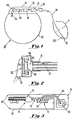
- Fig. 1 is a diagrammatic perspective of a pacing system in accordance with this invention, having an implantable pacemaker interconnected with a pacing lead, the distal portion of the pacing lead being inserted in the patient's heart.
- Fig. 2 is a detailed diagram representative of a first embodiment having a pressure transducer mounted within in a cavity within the header portion of the pacemaker.
- Fig. 3 is a detailed diagram illustrating another embodiment wherein the pressure signal from the lead is connected through a feed-through from the header portion to a pressure sensor mounted within the pacemaker can.
- Fig. 4 is a block diagram illustrating the primary portions of the pacemaker in accordance with this invention, and the interconnection of the pacing lead to the pacemaker.
- Fig. 5 is a flow diagram representing the primary processing steps taken to utilize the pressure signal data obtained in accordance with this invention.
- FIG. 1 there is shown an illustration of a pacemaker system in accordance with this invention, comprising generally a pacemaker 28 and a lead 34.
- the pacemaker 28 has a can, or container 30 which houses the pacemaker electronics, and a header or connector portion 32, sometimes also referred to as the connector assembly.
- the can 30 provides a hermetically sealed container for protection of the pulse generator and other electronics contained therein from body fluids.
- the connector assembly 32 provides the mechanical and electrical connection between the pacemaker and the lead, in a well-known fashion.
- U.S. Patents Nos. 5,188,078; 5,312,441; and 5,342,406 all incorporated herein by reference which disclose the structure of a connector assembly together with an implantable pulse generator or an implantable pacemaker - cardioverter - defibrillator.
- Lead 34 is shown as having a tip electrode 35 at about its distal end 35E, which appropriately is inserted into the apex of the right ventricle.
- the lead has a proximal end 36, which is inserted into opening or bore 31 formed in connector housing 33, suitably composed of uncolored, transparent epoxy.
- a first connector block 38 which is used for making electrical contact with a conductor which extends to the ring electrode of a bipolar lead, and second connector block 39 for making electrical contact with a conductor that extends to the tip electrode.
- the connector blocks may have a screw for fixation of the inserted lead, or a lead retainer comprising a spring contact.
- a pressure transducer 44 located to receive pressure signals communicated through the lumen of lead 34, and a feed-through element 45 for feeding the electrical signals from sensor 44 through to the interior of the pacemaker.
- the term standard pacing lead refers to one which has a central lumen, e.g., one through which a stylet may be inserted during the implantation procedure, and has conventional distal and proximal ends.
- the lead has an inner lumen 37, typically centrally located within a coil which runs the length of the lead, the coil providing electrical interconnections between the proximal end and the distal electrode or electrodes.
- Lumen 37 opens at 43, the opening being a size to receive a stylet. Opening 43 opens into a cavity 66, provided in the header portion.
- a pressure sensor element 44 is mounted in close proximity to the lumen opening 43. In practice, it is important to make the cavity as small as possible, so as to have good transmission matching of the lumen to the cavity.
- the volume of this cavity, or chamber adds to the volume of the lumen, such that the larger this cavity the smaller the available pressure change; the cavity volume is preferably significantly smaller than the volume of the lumen.
- the pressure sensor element is constructed from two layers, namely a silicon back plate 65 and a silicon diaphragm 68, which are sealed together. The cavity inside this construction is evacuated, to create an absolute pressure sensor.
- the output of the sensor is taken by leads 70 and communicated by a feed-through element to the interior of the pacemaker can 30, as discussed in more detail in connection with Fig. 4.
- Fig. 3 there is shown an alternate embodiment, wherein the pressure signal is transmitted from the lumen opening 43 through can 30 to transducer 50 by a feed-through capillary tube 45 which feeds through both the can 30 and a ceramic feed-through plate 73, as shown.
- the capillary tube material can be an isolator, e.g., a suitable plastic tube, or a metal tube for a combined electrical and pressure feed-through.
- the medium within the tube may be simply air, or it can be filled with a suitable gel which transmits the pressure signals.
- feed-through tube 45 which is within the pacemaker can interfaces directly to the sensor element of sensor 50, which in turn is mounted within a cavity formed by the feed-through plate 73 and a sealed inner cover 72, as shown.
- the sealed inner cover provides protection against sensor membrane damage, and consequent leakage into the inside of the pacemaker.
- the volume within cover 72 is evacuated, to avoid any influence of the gas pressure within it due to temperature variation.
- the signal output of the sensor is connected through one or more wire 74 to a hybrid circuit illustrated at 75.
- a metal tube is utilized to provide both the capillary tube for transmitting the pressure signal and the electrical connection to the tip electrode.
- the metal tube must be shaped to connect properly to the terminal portion 39 and also interface with the opening 43 of the lumen.
- the ceramic feed-through plate 73 contains a conductor (not shown) to pick up the electrical signal from the metal tube and couple it to the hybrid circuit.
- Fig. 4 there is shown a diagram of the pacemaker portion of the pacing system of this invention.
- the lead 34 has its proximal end connected to the pacemaker within the header section 32.
- a feed-through 47 is shown for connecting electrical signals between the lead and the inside of the pacemaker can 30.
- a capillary feed-through 45 is shown for connecting pressure signals between the lead and a sensor 50 mounted internally to the pacemaker. It is to be understood that for the embodiment of Fig. 2, the feed-through 47 also carries the signals from the pressure sensor; while for the embodiment of Fig. 3 the feed-through 45 carries the pressure signals between the connector block and the inside of the pacemaker.
- the sensor signals are connected to a sensor signal amplifier 54, and following processing circuitry 55 which, among other things, filters out the DC component (in the case of an absolute pressure sensor) and creates a suitable signal for storage and use by the microprocessor, as discussed further in connection with Fig. 5.
- These circuits may be part of a hybrid circuit, as illustrated at 75 in Fig. 3.
- the processed sensor signals are connected to a control block 56, indicated in the drawing of Fig. 4 as including a microprocessor.
- the microprocessor in a known manner in the pacemaker art, generates a number of control signals for controlling pace pulse generator 48. One of these signals, indicated as rate, is derived in accordance with this invention from the processed pressure sensor signals.
- the output of the pace pulse generator is connected through feed-through 47 to the pacing lead.
- the output of the pace pulse generator is also connected back to the control circuit, such that the control circuit receives the information when a pace pulse has been delivered and also when a signal from the heart is transmitted from lead 34 back to the pacemaker.
- a diagnostics block 58 suitably containing memory for storing diagnostic information, including information gained from the pressure sensor. This information can be used in further control of the pacemaker operation, or can be stored for readout to external apparatus, in a known manner.
- any pacing lead which has a lumen running the length thereof is applicable for use in this invention.
- Tests containing a pressure sensor of the type KPY43A have been conducted, where an IS-1-type lead has been inserted into a header, and pressure changes applied to the distal end of the lead. The pressure changes cause a compression of the lead tube, which causes a relative change of pressure in the lumen. Measurements have indicated that a 40 mm Hg pressure change at the distal end causes a pressure change in the lumen of approximately 0.4 mm Hg, as detected at the proximal end.
- the invention as disclosed can be used with a standard pacing lead, it is also applicable with leads which are modified to be more sensitive at specific points, and in particular at the distal end.
- the lead can be made more sensitive to pressure changes at the distal end, i.e., have a high pressure transfer characteristic, or can be modified to be more sensitive to conversion of bending pressure into relative pressure changes. Even though the pressure changes detected are relative, they exhibit a morphology which can be processed to provide significant information for use in a pacing environment. Indeed, in dog tests performed using the system of this invention, the recorded pressure signal clearly showed atrial contractions and ventricular contractions.
- the atrial contractions are represented by smaller peaks than the ventricular contractions, they can be separated, or windowed out, so that both P-wave and QRS information is available.
- the system of this invention using either a standard pacing lead or one modified specially for conducting pressure signals from the heart, can be used in a dual chamber pacing context, and specifically for a VDD mode pacemaker.
- appropriate processing of the pressure signals can be performed so that ventricular pacing can be synchronized with respect to detected atrial contractions.
- the pressure signals may also contain other useful information concerning respiration, minute ventilation, etc.
- Fig. 5 there is shown a simplified block diagram illustrating the primary steps in electrical processing of the analog output from the sensor.
- the analog signal is amplified, and then connected to block 86 for bandpass filtering which is adapted to the signals that the system is looking for.
- the filtering may include filtering out the DC component in the case of an absolute pressure sensor, although this step need not be done in a system that uses relative pressure sensors.
- the filtered signal is captured by windowing and threshold detection. After this, the identified portions of the signal are converted into digital form and processed for the desired control purposes, e.g. for controlling the next ventricular and/or atrial pace pulses.
- the processing step may suitably compare these respective signals to attain enhanced atrial and ventricular signals with minimal crosstalk.
- the respective atrial and ventricular signals are separated out based upon windowing and comparative frequency or morphology characteristics of the signals.
- pressure data obtained by the system may be used, either in a pacemaker or other medical device environment.
- pressure data may be used to confirm evoked responses, or may be used in combination with an activity sensor to exclude false senses.
- the pressure signals may be combined with detected cardiac signals such as the QRS and T waves, for either control or diagnostic purposes.
- EMI detection and rejection may be enhanced by utilizing the pressure signals.
Abstract
Description
- This invention relates to the field of implantable medical devices and, more particularly, to a pacemaker system having a pacemaker which contains a pressure sensor in combination with a pacing lead which connects stimulus pulses to the patient's heart and which is operatively connected to the pacemaker so as to transmit cardiac pressure signals to the pressure sensor.
- In the area of implantable medical devices, there has been a substantial effort to develop sensors for obtaining information from a body organ such as the heart, or relating to a body function such as respiration. For these purposes, catheters and leads have been widely used with medical devices, both external and implantable, including pacemakers, cardioverter/defibrillators, drug dispensers, cardiac monitors, and a variety of different types of stimulators. The common system arrangement is to have one or more catheters, or leads which interconnect the device with the body organ or body location. The terms catheter and lead are used interchangeably here; as used in this specification, either a lead or catheter connects the device to the body location so as to transmit electrical signals between its distal end and the device, and/or pressure or other signals from the body location to the device. A pacing lead, for example, may include one or more electrodes at about its distal end, and a conductor running the length of the lead to transmit stimulus pulses to the heart and conduct heart signals back to the pacemaker. It is also known to have sensors incorporated into the lead for sensing parameters for operational and diagnostic use, with additional conductors connecting the sensor signals back to the proximal end of the lead/catheter, for connection to the pacemaker or other device. In addition to sensing cardiac electrical activity, sensors are used for sensing, eg, blood pressure waves, acoustic waves, respiratory sounds, etc. Thus, for a wide variety of applications there is a need for efficient transmission of signals from a body location to an implanted device. Although this invention embraces various such applications, it will be illustrated primarily in the environment of the preferred embodiment, a pacemaker system.
- Modern pacemaker systems have evolved greatly beyond the initial pacemakers which simply delivered a fixed rate of pacing pulses. Pacemakers are widely programmable to operate in different modes and to operate with different pacing parameters. Specifically, many pacemakers are rate responsive, meaning that they automatically sense the patient's demand, or need for rate variation, and adjust pacing rate accordingly. Pacemaker systems are also incorporating more sensor information relating to the patient's metabolic needs and cardiac history. The ability of the pacemaker to undertake additional diagnostic functions, and to accurately adapt pacemaker performance to metabolic needs, is dependent upon good sensor information.
- As is well known, rate responsive or rate adaptive pacemakers may utilize any one of a number of different sensors for obtaining different physiologically based signals. Sensors that provide an indication of actual heart performance are coming into greater use. For example, sensors are used for measuring the pressure inside the patient's right ventricle, intramyocardial pressure, or myocardial contractility. Sensing pressure within the patient's heart is known to offer good potential for accurate determination of the patient's needs. See U.S. Patent No. 5,353,800, assigned to Medtronic, Inc., which provides a discussion of the many different types of pressure sensors used in cardiac pacing systems.
- As discussed in the prior art, the approach to measuring pressure changes within the heart has generally involved special leads adapted to carry a sensor which is located within the heart. Thus, a pressure sensor is located on the pacing lead close to the distal tip end, preferably positioned to maximize the sensor response. Such a lead requires extra wires throughout the length of the lead, for interconnection of the sensor signal to the pacemaker. Further, packaging a sensor in a lead tip, while maintaining the requisite minimal lead dimensions, presents considerable difficulty. Thus, it would be advantageous, both for newly implanted pacing systems and for replacement systems, to provide the pacemaker itself with one or more pressure sensors which receive pressure signals representative of cardiac movement, which signals are transmitted through a standard pacing lead and delivered to the pacemaker-mounted sensor. Such an arrangement, as presented by this invention, renders unnecessary any special lead construction, and by-passes the problems of fabricating a sensor on the lead and properly positioning the sensor within the heart. Further, for a patient requiring pacemaker, or pulse generator replacement, and already having a standard lead, it would clearly be advantageous to be able to replace the pacemaker with one which contains apparatus for reliably receiving a pressure signal transmitted through the implanted pacing lead.
- There have been some prior art efforts to provide an implantable system with a catheter or lead which transmits a pressure signal from a body location such as the heart back to the control device, eg, the pacemaker. See, for example, U.S. Patents No. 4,763,646 to Lekholm, and 5,353,800 to Polmdorf et al. These patents provide suggestions of transmitting pressure signals to the interior of a pacemaker can, but do not disclose efficient structure for achieving this. There thus remains a significant need in the implantable device art, and the pacemaker art in particular, for a system which provides for reliable and useful chronic transmission of signals such as pressure signals from an interior body location to the implanted device.
- Accordingly, it is an object of this invention to provide an implantable medical device system, and particularly a pacemaker system, which achieves reliable and efficient transmission and coupling of pressure signals from a body location such as the heart to an implanted device such as a pacemaker, whereby accurate information can be obtained from such pressure signals.
- The preferred embodiment of the present invention provides a pacing system which meets the object of utilizing a pressure sensor positioned in the implantable pacemaker, as contrasted to a system having a pressure sensor fabricated within the lead portion which is positioned in the patient's heart. The invention provides for utilizing relative pressure signals which are transmitted from the patient's heart through the lumen of a standard pacing lead, or any other pacing lead, which signals are communicated to a pressure sensor mounted either within the pacemaker connector block, or within the encapsulated pacemaker can. By this arrangement, the pacemaker-mounted sensor receives detectable pressure variations representative of heart movement, i.e., contraction and relaxation, and is able to transform such relative pressure signals into parameter signals for use in controlling a pacemaker operating variable such as pacing rate. The system may employ a second reference sensor, and may employ plural lead/catheters for transmitting the pressure signals to the implanted device.
- Accordingly, there is provided a pacemaker system having a standard pacing lead with a central lumen, the pacing lead having a distal end which is inserted into the patient's heart, and a proximal end which is connected to the implanted pacemaker at the pacemaker connector block. The physical movement of the heart produces pressure changes in the outer wall or casing of the lead distal portion, which relative changes are transmitted to the interior lumen, and through the length of the lumen to the proximal end of the lead. In a first embodiment of the invention, a pressure transducer is positioned within the header, or connector block, at a distance from the lumen opening at the proximal end of the lead such that the relative pressure signals are effectively conveyed to the pressure sensor. Output signals from the pressure sensor are connected through an appropriate feed-through to the pacemaker, which uses the signals for any desired application, including pacing rate control and collection of diagnostic information. In another embodiment, the pressure sensor is mounted within the hermetically sealed pacemaker can, and the relative pressure variations transmitted through the lead lumen are further transmitted through a feed-through which interconnects the proximal lumen opening and the pressure sensor. The system of this invention is adaptable for providing a replacement pacemaker which can be implanted in any patient having a standard pacing lead or leads with a lumen, whereby the benefit of using pressure signals originating in or around the heart can be obtained.
- Fig. 1 is a diagrammatic perspective of a pacing system in accordance with this invention, having an implantable pacemaker interconnected with a pacing lead, the distal portion of the pacing lead being inserted in the patient's heart.
- Fig. 2 is a detailed diagram representative of a first embodiment having a pressure transducer mounted within in a cavity within the header portion of the pacemaker.
- Fig. 3 is a detailed diagram illustrating another embodiment wherein the pressure signal from the lead is connected through a feed-through from the header portion to a pressure sensor mounted within the pacemaker can.
- Fig. 4 is a block diagram illustrating the primary portions of the pacemaker in accordance with this invention, and the interconnection of the pacing lead to the pacemaker.
- Fig. 5 is a flow diagram representing the primary processing steps taken to utilize the pressure signal data obtained in accordance with this invention.
- Referring now to Fig. 1, there is shown an illustration of a pacemaker system in accordance with this invention, comprising generally a
pacemaker 28 and alead 34. Thepacemaker 28 has a can, orcontainer 30 which houses the pacemaker electronics, and a header orconnector portion 32, sometimes also referred to as the connector assembly. Thecan 30 provides a hermetically sealed container for protection of the pulse generator and other electronics contained therein from body fluids. Theconnector assembly 32 provides the mechanical and electrical connection between the pacemaker and the lead, in a well-known fashion. Reference is made to U.S. Patents Nos. 5,188,078; 5,312,441; and 5,342,406 all incorporated herein by reference which disclose the structure of a connector assembly together with an implantable pulse generator or an implantable pacemaker - cardioverter - defibrillator. -
Lead 34 is shown as having atip electrode 35 at about itsdistal end 35E, which appropriately is inserted into the apex of the right ventricle. Although only a single unipolar lead is shown, it is to be understood that this invention can be practiced with a single chamber lead or dual chamber leads, and the leads can be unipolar or bipolar. The lead has aproximal end 36, which is inserted into opening orbore 31 formed inconnector housing 33, suitably composed of uncolored, transparent epoxy. There is illustrated afirst connector block 38 which is used for making electrical contact with a conductor which extends to the ring electrode of a bipolar lead, andsecond connector block 39 for making electrical contact with a conductor that extends to the tip electrode. The connector blocks may have a screw for fixation of the inserted lead, or a lead retainer comprising a spring contact. There is also illustrated apressure transducer 44, located to receive pressure signals communicated through the lumen oflead 34, and a feed-throughelement 45 for feeding the electrical signals fromsensor 44 through to the interior of the pacemaker. As used herein, the term standard pacing lead refers to one which has a central lumen, e.g., one through which a stylet may be inserted during the implantation procedure, and has conventional distal and proximal ends. - Referring now to Fig. 2, there is illustrated the details of the
proximal end 36 of the lead, and its placement relative to apressure transducer 44. The lead has aninner lumen 37, typically centrally located within a coil which runs the length of the lead, the coil providing electrical interconnections between the proximal end and the distal electrode or electrodes.Lumen 37 opens at 43, the opening being a size to receive a stylet.Opening 43 opens into acavity 66, provided in the header portion. Apressure sensor element 44 is mounted in close proximity to thelumen opening 43. In practice, it is important to make the cavity as small as possible, so as to have good transmission matching of the lumen to the cavity. The volume of this cavity, or chamber, adds to the volume of the lumen, such that the larger this cavity the smaller the available pressure change; the cavity volume is preferably significantly smaller than the volume of the lumen. For a lead with a lumen volume in the range of 110-140 mm3, a cavity volume which is only 10% as large would be about 14 mm3. The pressure sensor element is constructed from two layers, namely a silicon backplate 65 and asilicon diaphragm 68, which are sealed together. The cavity inside this construction is evacuated, to create an absolute pressure sensor. In this embodiment, the output of the sensor is taken byleads 70 and communicated by a feed-through element to the interior of the pacemaker can 30, as discussed in more detail in connection with Fig. 4. - Referring now to Fig. 3, there is shown an alternate embodiment, wherein the pressure signal is transmitted from the
lumen opening 43 throughcan 30 totransducer 50 by a feed-throughcapillary tube 45 which feeds through both thecan 30 and a ceramic feed-throughplate 73, as shown. The capillary tube material can be an isolator, e.g., a suitable plastic tube, or a metal tube for a combined electrical and pressure feed-through. The medium within the tube may be simply air, or it can be filled with a suitable gel which transmits the pressure signals. The end of feed-throughtube 45 which is within the pacemaker can interfaces directly to the sensor element ofsensor 50, which in turn is mounted within a cavity formed by the feed-throughplate 73 and a sealedinner cover 72, as shown. The sealed inner cover provides protection against sensor membrane damage, and consequent leakage into the inside of the pacemaker. The volume withincover 72 is evacuated, to avoid any influence of the gas pressure within it due to temperature variation. The signal output of the sensor is connected through one ormore wire 74 to a hybrid circuit illustrated at 75. - In a specific embodiment of a combined feed-through
tube 45, a metal tube is utilized to provide both the capillary tube for transmitting the pressure signal and the electrical connection to the tip electrode. The metal tube must be shaped to connect properly to theterminal portion 39 and also interface with theopening 43 of the lumen. In this embodiment, the ceramic feed-throughplate 73 contains a conductor (not shown) to pick up the electrical signal from the metal tube and couple it to the hybrid circuit. - Referring now to Fig. 4, there is shown a diagram of the pacemaker portion of the pacing system of this invention. As indicated, the
lead 34 has its proximal end connected to the pacemaker within theheader section 32. A feed-through 47 is shown for connecting electrical signals between the lead and the inside of the pacemaker can 30. Also, a capillary feed-through 45 is shown for connecting pressure signals between the lead and asensor 50 mounted internally to the pacemaker. It is to be understood that for the embodiment of Fig. 2, the feed-through 47 also carries the signals from the pressure sensor; while for the embodiment of Fig. 3 the feed-through 45 carries the pressure signals between the connector block and the inside of the pacemaker. - Whether the sensor is mounted within the
header 32 or within thecan 30, the sensor signals are connected to asensor signal amplifier 54, and followingprocessing circuitry 55 which, among other things, filters out the DC component (in the case of an absolute pressure sensor) and creates a suitable signal for storage and use by the microprocessor, as discussed further in connection with Fig. 5. These circuits may be part of a hybrid circuit, as illustrated at 75 in Fig. 3. The processed sensor signals are connected to acontrol block 56, indicated in the drawing of Fig. 4 as including a microprocessor. The microprocessor, in a known manner in the pacemaker art, generates a number of control signals for controllingpace pulse generator 48. One of these signals, indicated as rate, is derived in accordance with this invention from the processed pressure sensor signals. The output of the pace pulse generator is connected through feed-through 47 to the pacing lead. The output of the pace pulse generator is also connected back to the control circuit, such that the control circuit receives the information when a pace pulse has been delivered and also when a signal from the heart is transmitted fromlead 34 back to the pacemaker. Also shown is adiagnostics block 58, suitably containing memory for storing diagnostic information, including information gained from the pressure sensor. This information can be used in further control of the pacemaker operation, or can be stored for readout to external apparatus, in a known manner. - It is to be noted that the invention as described does not require any special lead. Thus, any pacing lead which has a lumen running the length thereof, as is the case for a standard pacing lead adapted to receive a stylet, is applicable for use in this invention. Tests containing a pressure sensor of the type KPY43A have been conducted, where an IS-1-type lead has been inserted into a header, and pressure changes applied to the distal end of the lead. The pressure changes cause a compression of the lead tube, which causes a relative change of pressure in the lumen. Measurements have indicated that a 40 mm Hg pressure change at the distal end causes a pressure change in the lumen of approximately 0.4 mm Hg, as detected at the proximal end.
- While the invention as disclosed can be used with a standard pacing lead, it is also applicable with leads which are modified to be more sensitive at specific points, and in particular at the distal end. The lead can be made more sensitive to pressure changes at the distal end, i.e., have a high pressure transfer characteristic, or can be modified to be more sensitive to conversion of bending pressure into relative pressure changes. Even though the pressure changes detected are relative, they exhibit a morphology which can be processed to provide significant information for use in a pacing environment. Indeed, in dog tests performed using the system of this invention, the recorded pressure signal clearly showed atrial contractions and ventricular contractions. Although the atrial contractions are represented by smaller peaks than the ventricular contractions, they can be separated, or windowed out, so that both P-wave and QRS information is available. Thus, the system of this invention, using either a standard pacing lead or one modified specially for conducting pressure signals from the heart, can be used in a dual chamber pacing context, and specifically for a VDD mode pacemaker. Thus, appropriate processing of the pressure signals can be performed so that ventricular pacing can be synchronized with respect to detected atrial contractions. The pressure signals may also contain other useful information concerning respiration, minute ventilation, etc.
- Referring now to Fig. 5, there is shown a simplified block diagram illustrating the primary steps in electrical processing of the analog output from the sensor. At
block 85, the analog signal is amplified, and then connected to block 86 for bandpass filtering which is adapted to the signals that the system is looking for. As noted above, the filtering may include filtering out the DC component in the case of an absolute pressure sensor, although this step need not be done in a system that uses relative pressure sensors. Next, atblock 88, the filtered signal is captured by windowing and threshold detection. After this, the identified portions of the signal are converted into digital form and processed for the desired control purposes, e.g. for controlling the next ventricular and/or atrial pace pulses. Of course, for a dual chamber pacemaker, there may be two leads providing separate atrial and ventricular pressure signals. The processing step may suitably compare these respective signals to attain enhanced atrial and ventricular signals with minimal crosstalk. Alternately, in the VDD embodiment, the respective atrial and ventricular signals are separated out based upon windowing and comparative frequency or morphology characteristics of the signals. - It is to be noted that the invention as claimed is not limited by the applications to which the pressure data obtained by the system may be used, either in a pacemaker or other medical device environment. By way of example only, in the pacemaker environment, pressure data may be used to confirm evoked responses, or may be used in combination with an activity sensor to exclude false senses. The pressure signals may be combined with detected cardiac signals such as the QRS and T waves, for either control or diagnostic purposes. Likewise, EMI detection and rejection may be enhanced by utilizing the pressure signals.
Claims (10)
- A pacemaker system having a pacemaker for delivering pacing pulses and a pacing lead for transmitting electrical signals between said pacemaker and a patient's heart, said lead having a distal end adapted to be placed in the patient's heart, a proximal end, and a lumen throughout its length suitable for transmitting pressure variations caused by heart activity, said lumen having a proximal opening at its proximal end, whereby pressure variations caused by said heart activity arise within said lumen and are transmitted to said proximal opening, said pacemaker having a connector portion for receiving the proximal end of said lead, a pressure sensor which produces signals corresponding to said transmitted pressure variations, and control means operatively connected to said pressure sensor for controlling pacemaker operation as a function of said transmitted pressure variations, characterized by:coupling means for coupling pressure variations between said lumen proximal opening and said pressure sensor, said coupling means having a cavity sized and positioned to receive said pressure variations, and mounting means for mounting said sensor in said cavity.
- The pacemaker system as described in claim 1, wherein said lead has a distal portion with a high pressure transfer characteristic for enabling transfer of cardiac pressure variations into said lead lumen.
- The pacemaker system as described in claim 1, wherein said pacemaker comprises a first sealed portion containing a pulse generator and said control means, first feed-through means for connecting electrical signals between said first portion and said connector portion, and second feed-through means for connecting said sensor signals to said control means.
- The pacemaker system as described in claim 1, wherein said pacemaker comprises a first portion containing a pulse generator and said control means, and wherein said pressure sensor is mounted in said first portion.
- The pacemaker system as described in claim 4, comprising sealing means for sealing said first portion from entry of body fluids, and wherein said coupling means comprises feed-through means for feeding said pressure variations from said proximal opening to said sensor.
- The pacemaker system as described in claim 1, wherein said cavity and said sensor are positioned in said connector portion.
- The pacemaker system as described in claim 6, wherein said cavity has a size that provides an efficient match to receive said transmitted pressure variations.
- The pacemaker system as described in claim 7, wherein said lumen has a first volume and said cavity has a second volume, and said second volume is no greater than about 10% of said first volume.
- The pacemaker system as described in claim 1, wherein said sensor is positioned in a second portion of said pacemaker.
- The pacemaker as described in claim 9, comprising a pressure feed-through for connecting said pressure variations to said sensor.
Applications Claiming Priority (2)
| Application Number | Priority Date | Filing Date | Title |
|---|---|---|---|
| US08/625,714 US6223081B1 (en) | 1996-03-28 | 1996-03-28 | Implantable stimulus system having stimulus generator with pressure sensor and common lead for transmitting stimulus pulses to a body location and pressure signals from the body location to the stimulus generator |
| US625714 | 1996-03-28 |
Publications (3)
| Publication Number | Publication Date |
|---|---|
| EP0798016A2 true EP0798016A2 (en) | 1997-10-01 |
| EP0798016A3 EP0798016A3 (en) | 1998-12-16 |
| EP0798016B1 EP0798016B1 (en) | 2003-12-17 |
Family
ID=24507254
Family Applications (1)
| Application Number | Title | Priority Date | Filing Date |
|---|---|---|---|
| EP97103142A Expired - Lifetime EP0798016B1 (en) | 1996-03-28 | 1997-02-26 | Implantable stimulus system having stimulus generator with pressure sensor and common lead for transmitting stimulus pulses to a body location and pressure signals from the body location to the stimulus generator |
Country Status (4)
| Country | Link |
|---|---|
| US (1) | US6223081B1 (en) |
| EP (1) | EP0798016B1 (en) |
| JP (1) | JPH1024109A (en) |
| DE (1) | DE69726783T2 (en) |
Cited By (6)
| Publication number | Priority date | Publication date | Assignee | Title |
|---|---|---|---|---|
| US6450942B1 (en) | 1999-08-20 | 2002-09-17 | Cardiorest International Ltd. | Method for reducing heart loads in mammals |
| US6677477B2 (en) | 2001-04-04 | 2004-01-13 | Kemira Chemicals Oy | Process for the production of peracetic acid |
| WO2007025163A1 (en) | 2005-08-26 | 2007-03-01 | Cardiac Pacemakers, Inc. | Broadband acoustic sensor for an implantable medical device |
| US7252005B2 (en) | 2003-08-22 | 2007-08-07 | Alfred E. Mann Foundation For Scientific Research | System and apparatus for sensing pressure in living organisms and inanimate objects |
| US7347826B1 (en) | 2003-10-16 | 2008-03-25 | Pacesetter, Inc. | Packaging sensors for long term implant |
| US9731141B2 (en) | 2007-06-14 | 2017-08-15 | Cardiac Pacemakers, Inc. | Multi-element acoustic recharging system |
Families Citing this family (47)
| Publication number | Priority date | Publication date | Assignee | Title |
|---|---|---|---|---|
| US20020120200A1 (en) * | 1997-10-14 | 2002-08-29 | Brian Brockway | Devices, systems and methods for endocardial pressure measurement |
| US20060064135A1 (en) * | 1997-10-14 | 2006-03-23 | Transoma Medical, Inc. | Implantable pressure sensor with pacing capability |
| US20030036746A1 (en) | 2001-08-16 | 2003-02-20 | Avi Penner | Devices for intrabody delivery of molecules and systems and methods utilizing same |
| US6491639B1 (en) * | 1999-11-10 | 2002-12-10 | Pacesetter, Inc. | Extravascular hemodynamic sensor |
| US6477406B1 (en) * | 1999-11-10 | 2002-11-05 | Pacesetter, Inc. | Extravascular hemodynamic acoustic sensor |
| US6970742B2 (en) * | 2000-01-11 | 2005-11-29 | Savacor, Inc. | Method for detecting, diagnosing, and treating cardiovascular disease |
| US8298150B2 (en) | 2000-01-11 | 2012-10-30 | Cedars-Sinai Medical Center | Hemodynamic waveform-based diagnosis and treatment |
| US6328699B1 (en) * | 2000-01-11 | 2001-12-11 | Cedars-Sinai Medical Center | Permanently implantable system and method for detecting, diagnosing and treating congestive heart failure |
| US6859667B2 (en) * | 2001-11-07 | 2005-02-22 | Cardiac Pacemakers, Inc. | Multiplexed medical device lead with standard header |
| ATE536201T1 (en) * | 2002-09-26 | 2011-12-15 | Pacesetter Inc | CARDIOVASCULAR ANCHORING DEVICE |
| US8303511B2 (en) | 2002-09-26 | 2012-11-06 | Pacesetter, Inc. | Implantable pressure transducer system optimized for reduced thrombosis effect |
| WO2005062823A2 (en) * | 2003-12-19 | 2005-07-14 | Savacor, Inc. | Digital electrode for cardiac rhythm management |
| US7756581B2 (en) * | 2004-02-18 | 2010-07-13 | Medtronic, Inc. | Implantable temperature sensor |
| DE602005024179D1 (en) * | 2004-11-24 | 2010-11-25 | Remon Medical Technologies Ltd | IMPLANTABLE MEDICINE PRODUCT WITH INTEGRATED ACOUSTIC CONVERTER |
| US7522962B1 (en) | 2004-12-03 | 2009-04-21 | Remon Medical Technologies, Ltd | Implantable medical device with integrated acoustic transducer |
| US20060149330A1 (en) * | 2004-12-30 | 2006-07-06 | Brian Mann | Digitally controlled cardiac rhythm management |
| US20060149324A1 (en) * | 2004-12-30 | 2006-07-06 | Brian Mann | Cardiac rhythm management with interchangeable components |
| US7927282B2 (en) * | 2005-07-19 | 2011-04-19 | Medtronic, Inc. | System and method of determining cardiac pressure |
| US7972273B2 (en) * | 2005-07-19 | 2011-07-05 | Medtronic, Inc. | System and method of determining cardiac pressure |
| US7850615B2 (en) * | 2005-07-19 | 2010-12-14 | Medtronic, Inc. | System and method of determining cardiac pressure |
| US7785264B2 (en) * | 2005-07-19 | 2010-08-31 | Medtronic, Inc. | System and method of determining cardiac pressure |
| US7570998B2 (en) * | 2005-08-26 | 2009-08-04 | Cardiac Pacemakers, Inc. | Acoustic communication transducer in implantable medical device header |
| US20070049980A1 (en) | 2005-08-30 | 2007-03-01 | Zielinski Todd M | Trans-septal pressure sensor |
| US20070073351A1 (en) | 2005-09-27 | 2007-03-29 | Zielinski Todd M | Trans-septal anchoring system and method |
| US20070073370A1 (en) * | 2005-09-27 | 2007-03-29 | Zielinski Todd M | Trans-septal anchoring system and method |
| EP2471451A1 (en) | 2005-10-14 | 2012-07-04 | Nanostim, Inc. | Leadless cardiac pacemaker and system |
| US9168383B2 (en) | 2005-10-14 | 2015-10-27 | Pacesetter, Inc. | Leadless cardiac pacemaker with conducted communication |
| JP2007159869A (en) * | 2005-12-14 | 2007-06-28 | Jms Co Ltd | Implantable cardioverter defibrillator |
| US8095198B2 (en) * | 2006-01-31 | 2012-01-10 | Warsaw Orthopedic. Inc. | Methods for detecting osteolytic conditions in the body |
| US7918796B2 (en) * | 2006-04-11 | 2011-04-05 | Warsaw Orthopedic, Inc. | Volumetric measurement and visual feedback of tissues |
| EP2043740A2 (en) * | 2006-07-21 | 2009-04-08 | Cardiac Pacemakers, Inc. | Ultrasonic transducer for a metallic cavity implanted medical device |
| US7912548B2 (en) * | 2006-07-21 | 2011-03-22 | Cardiac Pacemakers, Inc. | Resonant structures for implantable devices |
| US9044537B2 (en) * | 2007-03-30 | 2015-06-02 | Medtronic, Inc. | Devices and methods for detecting catheter complications |
| US8825161B1 (en) | 2007-05-17 | 2014-09-02 | Cardiac Pacemakers, Inc. | Acoustic transducer for an implantable medical device |
| US8406898B2 (en) | 2007-09-27 | 2013-03-26 | Cardiac Pacemakers, Inc. | Implantable lead with an electrostimulation capacitor |
| US7945324B2 (en) * | 2008-06-30 | 2011-05-17 | Data Sciences International, Inc. | Pressure sensing lead systems for implantable stimulators |
| US8527068B2 (en) | 2009-02-02 | 2013-09-03 | Nanostim, Inc. | Leadless cardiac pacemaker with secondary fixation capability |
| US9060692B2 (en) | 2010-10-12 | 2015-06-23 | Pacesetter, Inc. | Temperature sensor for a leadless cardiac pacemaker |
| CN103249452A (en) | 2010-10-12 | 2013-08-14 | 内诺斯蒂姆股份有限公司 | Temperature sensor for a leadless cardiac pacemaker |
| WO2012051235A1 (en) | 2010-10-13 | 2012-04-19 | Nanostim, Inc. | Leadless cardiac pacemaker with anti-unscrewing feature |
| CN103402578B (en) | 2010-12-13 | 2016-03-02 | 内诺斯蒂姆股份有限公司 | Pacemaker recovery system and method |
| US8615310B2 (en) | 2010-12-13 | 2013-12-24 | Pacesetter, Inc. | Delivery catheter systems and methods |
| US9242102B2 (en) | 2010-12-20 | 2016-01-26 | Pacesetter, Inc. | Leadless pacemaker with radial fixation mechanism |
| WO2013067496A2 (en) | 2011-11-04 | 2013-05-10 | Nanostim, Inc. | Leadless cardiac pacemaker with integral battery and redundant welds |
| US10123717B2 (en) * | 2011-11-10 | 2018-11-13 | Neuropace, Inc. | Multimodal brain sensing lead |
| WO2014022661A1 (en) | 2012-08-01 | 2014-02-06 | Nanostim, Inc. | Biostimulator circuit with flying cell |
| WO2019036600A1 (en) * | 2017-08-18 | 2019-02-21 | Cardiac Pacemakers, Inc. | Implantable medical device with pressure sensor |
Citations (6)
| Publication number | Priority date | Publication date | Assignee | Title |
|---|---|---|---|---|
| EP0249338A2 (en) * | 1986-06-12 | 1987-12-16 | C.R. Bard, Inc. | Retroperfusion catheter |
| US4763646A (en) * | 1985-10-04 | 1988-08-16 | Siemens Aktiengesellschaft | Heart pacemaker |
| US4834100A (en) * | 1986-05-12 | 1989-05-30 | Charms Bernard L | Apparatus and method of defibrillation |
| US4846191A (en) * | 1988-05-27 | 1989-07-11 | Data Sciences, Inc. | Device for chronic measurement of internal body pressure |
| US5154169A (en) * | 1990-03-16 | 1992-10-13 | Nippon Zeon Co., Ltd. | Pacing unit with catheter holder |
| WO1997035636A1 (en) * | 1996-03-28 | 1997-10-02 | Medtronic, Inc. | Detection of pressure waves transmitted through catheter/lead body |
Family Cites Families (8)
| Publication number | Priority date | Publication date | Assignee | Title |
|---|---|---|---|---|
| US4407296A (en) | 1980-09-12 | 1983-10-04 | Medtronic, Inc. | Integral hermetic impantable pressure transducer |
| US4899751A (en) * | 1987-10-06 | 1990-02-13 | Leonard Bloom | System for and method of therapeutic stimulation of a patient's heart |
| JP2612099B2 (en) | 1991-01-29 | 1997-05-21 | 株式会社日立製作所 | Throttle valve assembly |
| US5312441A (en) | 1992-04-13 | 1994-05-17 | Medtronic, Inc. | Method and apparatus for discrimination of ventricular tachycardia from supraventricular tachycardia and for treatment thereof |
| US5320643A (en) * | 1992-10-06 | 1994-06-14 | Medtronic, Inc. | Automatic cardiac capture restoration and threshold-seeking method and apparatus |
| US5342406A (en) | 1992-10-07 | 1994-08-30 | Medtronic, Inc. | Oxygen sensor based capture detection for a pacer |
| US5353800A (en) | 1992-12-11 | 1994-10-11 | Medtronic, Inc. | Implantable pressure sensor lead |
| US5556421A (en) * | 1995-02-22 | 1996-09-17 | Intermedics, Inc. | Implantable medical device with enclosed physiological parameter sensors or telemetry link |
-
1996
- 1996-03-28 US US08/625,714 patent/US6223081B1/en not_active Expired - Fee Related
-
1997
- 1997-02-26 EP EP97103142A patent/EP0798016B1/en not_active Expired - Lifetime
- 1997-02-26 DE DE69726783T patent/DE69726783T2/en not_active Expired - Lifetime
- 1997-03-28 JP JP9092879A patent/JPH1024109A/en active Pending
Patent Citations (6)
| Publication number | Priority date | Publication date | Assignee | Title |
|---|---|---|---|---|
| US4763646A (en) * | 1985-10-04 | 1988-08-16 | Siemens Aktiengesellschaft | Heart pacemaker |
| US4834100A (en) * | 1986-05-12 | 1989-05-30 | Charms Bernard L | Apparatus and method of defibrillation |
| EP0249338A2 (en) * | 1986-06-12 | 1987-12-16 | C.R. Bard, Inc. | Retroperfusion catheter |
| US4846191A (en) * | 1988-05-27 | 1989-07-11 | Data Sciences, Inc. | Device for chronic measurement of internal body pressure |
| US5154169A (en) * | 1990-03-16 | 1992-10-13 | Nippon Zeon Co., Ltd. | Pacing unit with catheter holder |
| WO1997035636A1 (en) * | 1996-03-28 | 1997-10-02 | Medtronic, Inc. | Detection of pressure waves transmitted through catheter/lead body |
Cited By (11)
| Publication number | Priority date | Publication date | Assignee | Title |
|---|---|---|---|---|
| US6450942B1 (en) | 1999-08-20 | 2002-09-17 | Cardiorest International Ltd. | Method for reducing heart loads in mammals |
| US6832982B1 (en) | 1999-08-20 | 2004-12-21 | Coral Licensing International Ltd. | Method of treating a living organism to achieve a heart load reduction, and apparatus for carrying out the method |
| US6677477B2 (en) | 2001-04-04 | 2004-01-13 | Kemira Chemicals Oy | Process for the production of peracetic acid |
| US7252005B2 (en) | 2003-08-22 | 2007-08-07 | Alfred E. Mann Foundation For Scientific Research | System and apparatus for sensing pressure in living organisms and inanimate objects |
| EP1969998A2 (en) | 2003-08-22 | 2008-09-17 | Alfred E. Mann Foundation for Scientific Research | System and apparatus for sensing pressure in living organisms and inanimate objects |
| EP1969998A3 (en) * | 2003-08-22 | 2008-10-08 | Alfred E. Mann Foundation for Scientific Research | System and apparatus for sensing pressure in living organisms and inanimate objects |
| EP1508295B1 (en) * | 2003-08-22 | 2008-12-17 | Alfred E. Mann Foundation for Scientific Research | System and apparatus for sensing pressure in living organisms and inanimate objects |
| US7347826B1 (en) | 2003-10-16 | 2008-03-25 | Pacesetter, Inc. | Packaging sensors for long term implant |
| WO2007025163A1 (en) | 2005-08-26 | 2007-03-01 | Cardiac Pacemakers, Inc. | Broadband acoustic sensor for an implantable medical device |
| JP4889127B2 (en) * | 2005-08-26 | 2012-03-07 | カーディアック ペースメイカーズ, インコーポレイテッド | Broadband acoustic sensor for implantable medical devices |
| US9731141B2 (en) | 2007-06-14 | 2017-08-15 | Cardiac Pacemakers, Inc. | Multi-element acoustic recharging system |
Also Published As
| Publication number | Publication date |
|---|---|
| EP0798016B1 (en) | 2003-12-17 |
| US6223081B1 (en) | 2001-04-24 |
| DE69726783T2 (en) | 2004-12-09 |
| EP0798016A3 (en) | 1998-12-16 |
| JPH1024109A (en) | 1998-01-27 |
| DE69726783D1 (en) | 2004-01-29 |
Similar Documents
| Publication | Publication Date | Title |
|---|---|---|
| EP0798016B1 (en) | Implantable stimulus system having stimulus generator with pressure sensor and common lead for transmitting stimulus pulses to a body location and pressure signals from the body location to the stimulus generator | |
| US6234973B1 (en) | Implantable medical device for sensing absolute blood pressure and barometric pressure | |
| US4485813A (en) | Implantable dynamic pressure transducer system | |
| US5899927A (en) | Detection of pressure waves transmitted through catheter/lead body | |
| US6292697B1 (en) | Testing sterile packaged components of an implantable medical device prior to chronic implantation | |
| US8155758B2 (en) | Fault tolerant implantable pulse generators and implantable cardioverter-defibrillators incorporating physiologic sensors and methods for implementing fault tolerance in same | |
| US6248080B1 (en) | Intracranial monitoring and therapy delivery control device, system and method | |
| US20070265666A1 (en) | Implantable sensors having high impedance couplings providing current pathways for improved fault tolerance | |
| US7818051B2 (en) | Wireless ECG in implantable devices | |
| US20070265671A1 (en) | Selectable switching of implantable sensors to provide fault toleance for implantable medical devices | |
| US20070265674A1 (en) | Fault tolerant implantable sensors having redundant electrical grounding connections | |
| JP4861323B2 (en) | Techniques for blood pressure measurement with implantable devices | |
| US5824029A (en) | Implantable medical system for performing transthoracic impedance measurements associated with cardiac function | |
| US20070265668A1 (en) | Fault tolerant sensors and methods for implementing fault tolerance in implantable medical devices | |
| US7650191B1 (en) | Implantable medical device having a header with an integrated telemetry coil | |
| US5174303A (en) | Pacer lead with replaceable sensor | |
| US20070255352A1 (en) | Implantable sensors having current-based switches for improved fault tolerance | |
| US20070265662A1 (en) | Implantable electromagnetic interference tolerant, wired sensors and methods for implementing same | |
| JPH11500930A (en) | Implantable medical device with sealed physiological parameter sensor or telemetry link | |
| US20080103406A1 (en) | Integrated system for managing patients with heart failure | |
| US20110208262A1 (en) | Lead-carried proximal electrode for quadripolar transthoracic impedance monitoring | |
| US20070255353A1 (en) | Fault tolerant co-axially wired sensors and methods for implementing same in an implantable medical device | |
| WO2022253691A1 (en) | Implantable medical device comprising an electrical line forming an antenna | |
| CN116634926A (en) | IMD housing containing a feedthrough formed using a dielectric material | |
| US20090326598A1 (en) | Pressure Sensing Lead Systems for Implantable Stimulators |
Legal Events
| Date | Code | Title | Description |
|---|---|---|---|
| PUAI | Public reference made under article 153(3) epc to a published international application that has entered the european phase |
Free format text: ORIGINAL CODE: 0009012 |
|
| AK | Designated contracting states |
Kind code of ref document: A2 Designated state(s): CH DE GB IT LI NL SE |
|
| PUAL | Search report despatched |
Free format text: ORIGINAL CODE: 0009013 |
|
| AK | Designated contracting states |
Kind code of ref document: A3 Designated state(s): CH DE GB IT LI NL SE |
|
| 17P | Request for examination filed |
Effective date: 19990408 |
|
| GRAP | Despatch of communication of intention to grant a patent |
Free format text: ORIGINAL CODE: EPIDOSNIGR1 |
|
| GRAS | Grant fee paid |
Free format text: ORIGINAL CODE: EPIDOSNIGR3 |
|
| GRAA | (expected) grant |
Free format text: ORIGINAL CODE: 0009210 |
|
| AK | Designated contracting states |
Kind code of ref document: B1 Designated state(s): CH DE GB IT LI NL SE |
|
| REG | Reference to a national code |
Ref country code: GB Ref legal event code: FG4D |
|
| REG | Reference to a national code |
Ref country code: CH Ref legal event code: EP |
|
| REF | Corresponds to: |
Ref document number: 69726783 Country of ref document: DE Date of ref document: 20040129 Kind code of ref document: P |
|
| REG | Reference to a national code |
Ref country code: SE Ref legal event code: TRGR |
|
| REG | Reference to a national code |
Ref country code: CH Ref legal event code: NV Representative=s name: ISLER & PEDRAZZINI AG |
|
| PLBE | No opposition filed within time limit |
Free format text: ORIGINAL CODE: 0009261 |
|
| STAA | Information on the status of an ep patent application or granted ep patent |
Free format text: STATUS: NO OPPOSITION FILED WITHIN TIME LIMIT |
|
| 26N | No opposition filed |
Effective date: 20040920 |
|
| PGFP | Annual fee paid to national office [announced via postgrant information from national office to epo] |
Ref country code: GB Payment date: 20070105 Year of fee payment: 11 |
|
| PGFP | Annual fee paid to national office [announced via postgrant information from national office to epo] |
Ref country code: NL Payment date: 20070108 Year of fee payment: 11 |
|
| PGFP | Annual fee paid to national office [announced via postgrant information from national office to epo] |
Ref country code: CH Payment date: 20070110 Year of fee payment: 11 |
|
| PGFP | Annual fee paid to national office [announced via postgrant information from national office to epo] |
Ref country code: SE Payment date: 20070205 Year of fee payment: 11 |
|
| REG | Reference to a national code |
Ref country code: CH Ref legal event code: PCAR Free format text: ISLER & PEDRAZZINI AG;POSTFACH 1772;8027 ZUERICH (CH) |
|
| PGFP | Annual fee paid to national office [announced via postgrant information from national office to epo] |
Ref country code: IT Payment date: 20070526 Year of fee payment: 11 |
|
| REG | Reference to a national code |
Ref country code: CH Ref legal event code: PL |
|
| EUG | Se: european patent has lapsed | ||
| GBPC | Gb: european patent ceased through non-payment of renewal fee |
Effective date: 20080226 |
|
| PG25 | Lapsed in a contracting state [announced via postgrant information from national office to epo] |
Ref country code: LI Free format text: LAPSE BECAUSE OF NON-PAYMENT OF DUE FEES Effective date: 20080229 Ref country code: CH Free format text: LAPSE BECAUSE OF NON-PAYMENT OF DUE FEES Effective date: 20080229 |
|
| NLV4 | Nl: lapsed or anulled due to non-payment of the annual fee |
Effective date: 20080901 |
|
| PG25 | Lapsed in a contracting state [announced via postgrant information from national office to epo] |
Ref country code: NL Free format text: LAPSE BECAUSE OF NON-PAYMENT OF DUE FEES Effective date: 20080901 |
|
| PG25 | Lapsed in a contracting state [announced via postgrant information from national office to epo] |
Ref country code: SE Free format text: LAPSE BECAUSE OF NON-PAYMENT OF DUE FEES Effective date: 20080227 |
|
| PG25 | Lapsed in a contracting state [announced via postgrant information from national office to epo] |
Ref country code: GB Free format text: LAPSE BECAUSE OF NON-PAYMENT OF DUE FEES Effective date: 20080226 |
|
| PG25 | Lapsed in a contracting state [announced via postgrant information from national office to epo] |
Ref country code: IT Free format text: LAPSE BECAUSE OF NON-PAYMENT OF DUE FEES Effective date: 20080226 |
|
| PGFP | Annual fee paid to national office [announced via postgrant information from national office to epo] |
Ref country code: DE Payment date: 20120228 Year of fee payment: 16 |
|
| REG | Reference to a national code |
Ref country code: DE Ref legal event code: R119 Ref document number: 69726783 Country of ref document: DE Effective date: 20130903 |
|
| PG25 | Lapsed in a contracting state [announced via postgrant information from national office to epo] |
Ref country code: DE Free format text: LAPSE BECAUSE OF NON-PAYMENT OF DUE FEES Effective date: 20130903 |