EP0799362B1 - Method and apparatus for assembling custom glass assemblies - Google Patents
Method and apparatus for assembling custom glass assemblies Download PDFInfo
- Publication number
- EP0799362B1 EP0799362B1 EP95921595A EP95921595A EP0799362B1 EP 0799362 B1 EP0799362 B1 EP 0799362B1 EP 95921595 A EP95921595 A EP 95921595A EP 95921595 A EP95921595 A EP 95921595A EP 0799362 B1 EP0799362 B1 EP 0799362B1
- Authority
- EP
- European Patent Office
- Prior art keywords
- spacer
- glass
- pane
- gas exchange
- exchange chamber
- Prior art date
- Legal status (The legal status is an assumption and is not a legal conclusion. Google has not performed a legal analysis and makes no representation as to the accuracy of the status listed.)
- Expired - Lifetime
Links
Images


Classifications
-
- E—FIXED CONSTRUCTIONS
- E06—DOORS, WINDOWS, SHUTTERS, OR ROLLER BLINDS IN GENERAL; LADDERS
- E06B—FIXED OR MOVABLE CLOSURES FOR OPENINGS IN BUILDINGS, VEHICLES, FENCES OR LIKE ENCLOSURES IN GENERAL, e.g. DOORS, WINDOWS, BLINDS, GATES
- E06B3/00—Window sashes, door leaves, or like elements for closing wall or like openings; Layout of fixed or moving closures, e.g. windows in wall or like openings; Features of rigidly-mounted outer frames relating to the mounting of wing frames
- E06B3/66—Units comprising two or more parallel glass or like panes permanently secured together
- E06B3/677—Evacuating or filling the gap between the panes ; Equilibration of inside and outside pressure; Preventing condensation in the gap between the panes; Cleaning the gap between the panes
- E06B3/6775—Evacuating or filling the gap during assembly
-
- E—FIXED CONSTRUCTIONS
- E06—DOORS, WINDOWS, SHUTTERS, OR ROLLER BLINDS IN GENERAL; LADDERS
- E06B—FIXED OR MOVABLE CLOSURES FOR OPENINGS IN BUILDINGS, VEHICLES, FENCES OR LIKE ENCLOSURES IN GENERAL, e.g. DOORS, WINDOWS, BLINDS, GATES
- E06B3/00—Window sashes, door leaves, or like elements for closing wall or like openings; Layout of fixed or moving closures, e.g. windows in wall or like openings; Features of rigidly-mounted outer frames relating to the mounting of wing frames
- E06B3/66—Units comprising two or more parallel glass or like panes permanently secured together
- E06B3/673—Assembling the units
- E06B3/67365—Transporting or handling panes, spacer frames or units during assembly
- E06B3/67386—Presses; Clamping means holding the panes during assembly
Abstract
Description
- The present invention relates to a method and apparatus for assembling a small number of custom glass assemblies which may not have uniform sizes or shapes, and filling the glass assemblies with an insulating gas having a thermal conductivity that is less than that of air.
- Conventional multi-pane insulating glass assemblies generally have two substantially parallel, spaced apart panes which are separated by a peripheral spacer. The spacers commonly are formed metal tubes constructed so as to have two flat, substantially parallel sides facing the interior surfaces of the panes. The interior surfaces of the panes are bonded to the sides of the spacer by a sealant material such as polyisobutelyne. To enhance the thermal resistance across such glass assemblies, the interpane space between the panes is filled with an insulating gas having a thermal conductivity that is less than that of air.
- Glass assemblies are generally either uniform production line assemblies or custom made assemblies. Uniform production line glass assemblies are made in large quantities and all of the assemblies have the same size and shape. Because of the repetition involved in making uniform glass assemblies, it is generally cost effective to develop specific manufacturing assembly lines to manufacture large quantities of a single type glass assembly. Custom assemblies, on the other hand, are generally manufactured in very small quantities as low as a single assembly, and each assembly may have a unique size and shape.
- The interpane space of a multi-pane glass assembly is filled with an insulating gas by drawing a vacuum to remove the air within the interpane space before both panes are sealed to the spacer, and then replacing the air with an insulating gas such as argon. After the interpane space is filled with an insulating gas, the panes are sealed to the spacer so that the gas does not escape into the atmosphere.
- Several methods and apparatuses exist for assembling and replacing the air in a plurality of uniform glass assemblies. One method is disclosed in U.S. Patent No. 5,017,252, entitled METHOD FOR FABRICATING INSULATING GLASS ASSEMBLIES, and another method and apparatus is disclosed in U.S. Patent No. 4,780,164, entitled METHOD FOR PRODUCING GAS-CONTAINING INSULATING GLASS ASSEMBLIES. Several uniform glass assemblies may be simultaneously filled with gas in a single gas exchange cycle because the uniformity of the assemblies allows them to be arranged adjacent to one another so that the spacers are aligned with one another. The panes of each assembly are compressed against the adhesive on the spacer under either the weight of the adjacent assemblies or by a single hydraulically actuated platen. By arranging the assemblies so that the spacers are aligned with one another, the compressive forces are borne by the spacers and the glass aligned with the spacers. Accordingly, the only portions of the panes of a uniform glass assembly that bear any loading are those that are supported by the spacers. Yet, when custom glass assemblies are arranged in the same manner, there will be an unsupported portion in the larger of two adjacent panes because the spacers cannot be aligned. As such, conventional methods and devices for filling a plurality of uniform gas assemblies are not useful for filling custom glass assemblies.
- Another device for assembling and filling glass assemblies one at a time is disclosed in European Patent No. 0056762. The device disclosed in European Patent No. 0056762 includes a series of rollers inclined at an angle and an inclined surface which provides an air bearing to transport a single pane of glass and a spacer into a gas exchange chamber. The gas exchange chamber has a pivoting platen which carries the second pane. The first pane and spacer are moved into the chamber opposite the platen, and after an insulating gas has been exchanged for the air in the chamber, the second pane is pressed against the spacer to seal the interpane space between the panes. The device shown in European Patent No. 0056762 does not adequately seal custom glass assemblies having spacers of different widths without requiring significant adjustments of the pivoting platen. Moreover, it is difficult to properly align the first and second panes of custom glass assemblies in the device shown European Patent No. 0056762 because at least one of the panes is fixed to the platen before it is pressed against the spacer. As such, the other pane must be positioned on the rollers and the air bearing without knowing the precise alignment with the pane carried by the spacer. Because of the difficulty in aligning the panes, it would appear that experimentation is required to use the device discussed in European Patent No. 0056762 to properly align the panes of a custom glass assembly.
- The Applicant's earlier European application EP-A-0389706 discloses another method and apparatus for producing glass assemblies in which a separator is provided between the panes to space these and allow the air to be removed from the interpane space and be replaced with a desired gas. The separator is then removed allowing the units to close and seal the glass assembly.
- It would be advantageous to provide a method and apparatus for quickly assembling a small number of custom insulating glass assemblies and filling such glass assemblies with an insulating gas.
- According to the invention, a method of assembling custom multi-pane glass assemblies such as sealed double glazing units, in which a spacer having sealant on opposing surfaces thereof is adhered to a first glass pane, a member is positioned alongside a portion of the spacer, a second glass pane is positioned over the spacer so that it is partially adhered to the spacer to define an interpane space around which the spacer is adhered, but with the member preventing contact with the whole of the spacer so maintaining a gap between a portion of the spacer and the second glass pane, the resulting assembly is moved into a gas exchange chamber, air is removed from the chamber and accordingly also the interpane space, and a gas having a coefficient of thermal conductivity lower than that of air is introduced into the chamber and accordingly also the interpane space, is characterised in that the member is resilient, and in that the glass panes are pressed together while in the gas exchange chamber to compress the resilient member and adhere the second glass pane to all of the spacer to seal the interpane space.
- Also according to the invention an apparatus for assembling custom multi-pane glass assemblies such as sealed double glazing units, from a partial assembly comprising a first glass pane, a spacer having sealant on opposing surfaces therefore being adhered to said first glass pane to define an interpane space around which the spacer is adhered, a member positioned alongside a portion of that spacer outside the interpane space and a second glass pane positioned over the spacer with its lower edge supported by roller means so that the second glass pane is partially adhered to the spacer but with the member preventing contact with the whole of the spacer so maintaining a gap between a portion of the spacer and the second glass pane, said apparatus comprising a lay-up system having roller means onto which the first glass pane is laid to support it during adhesion of the spacer to said first glass pane, the member is positioned alongside said portion of the spacer and the second glass pane is positioned over the spacer, and which transport the resulting partially assembled glass assembly from the lay-up station, a gas exchange chamber into which the resulting assembly is moved from the lay-up station, means for removing air from the chamber, and means for introducing a gas having a coefficient of thermal conductivity lower than that of air into the chamber, is characterised in that the member is resilient and in that a platen is provided in the gas chamber, and in that means are provided for moving that platen against the second glass pane to compress the resilient member and adhere the second glass pane to all of the spacer to seal the interpane space.
- The present invention provides a method and apparatus for quickly assembling a small number of custom insulating glass assemblies in which the spacers are not necessarily the same width and the panes of different assemblies are not necessarily the same size or shape. The method includes providing an assembly line having a lay-up station, a gas exchange chamber and roller means for transporting a glass assembly from the lay-up station to the gas exchange chamber. The gas exchange chamber has a support surface to receive the glass assembly and at least one movable platen. The method continues by providing first and second glass panes which each have a bottom edge, a top portion, an interior surface and an exterior surface. A spacer which has a sealant disposed on opposing sides thereof, and a resilient member which has a width larger than the width of the spacer are also provided. The component parts of a glass assembly and the resilient member are then partially assembled by adhering the panes to the spacer while maintaining a gap between a portion of the spacer and one of the panes, and positioning the resilient member between the panes outwardly of the spacer to maintain the gap. The partially assembled glass assembly Is then translated into the gas exchange chamber where a vacuum is drawn so as to remove substantially all of the air within an interpane space through the gap. A gas having a coefficient of thermal conductivity lower than that of air is then admitted into the gas chamber until the interpane space is filled with the gas. The platen is then moved within the gas exchange chamber so as to compress the resilient member and sealingly adhere the interior surface of the second pane to the spacer, thereby eliminating the gap and substantially sealing the interpane space. The method concludes by removing the resilient member from the glass assembly.
- In a preferred embodiment of the invention, a press station is provided after the gas exchange chamber. The method of this embodiment includes further compressing the panes against the spacer to obtain the desired thickness of adhesive on both sides of the spacer.
- In addition, according to another preferred embodiment, the compressed resilient member is removed and a sealant is applied across at least a portion of the width of the spacer around the exterior perimeter thereof.
- The apparatus for assembling a small number of custom insulated multi-pane glazing units and filling the glass assemblies with an insulating gas includes a resilient member positionable between first and second panes of a glass assembly, a lay-up station and a gas exchange chamber. The lay-up station has a roller means for transporting the glass assembly from the lay-up station. The glass assembly is partially partly assembled on the lay-up station by adhering the panes to a spacer while maintaining a gap between a portion of the spacer and one of the panes, and positioning the resilient member between the panes outwardly of the spacer to maintain the gap. The gas exchange chamber is for replacing air within an interpane space between the panes of the glass assembly with an insulating gas having a coefficient of thermal conductivity that is less than that of air. The gas exchange chamber has a roller means and a support surface to receive the glass assembly, a vacuum for removing substantially all of the air within the chamber and the interpane space, a gas supply for filling the interpane space with the insulating gas and at least one platen positioned opposite the support surface. The platen is positionable opposite the glass assembly and is engageable with the second pane for compressing the resilient member so as to sealingly adhere the panes to the spacer, thereby eliminating the gap and sealing the interpane space.
- In a preferred embodiment of the invention, a press station is provided after the gas exchange chamber. The press station includes a roller means and a support surface to receive the glass assembly from the gas exchange chamber, and at least one press plate positioned opposite the support surface. At least one actuator is attached to the plate for moving the plate towards the support surface. The plate is controlled in a manner to precisely determine the distance that the plate is driven.
- The invention will now be described, by way of example, with reference to the accompanying drawings, in which:
- Figure 1 is a perspective view of an apparatus in accordance with the invention;
- Figure 2 is a front elevational view of the apparatus of Figure 1;
- Figure 3 is another front elevational view of the apparatus of Figure 1;
- Figure 4 is a partial cross-sectional side elevational view of a lay-up station of the apparatus of Figure 1 taken along line 4-4;
- Figure 5 is a partial cross-sectional side elevational view of a lay-up station of the apparatus of Figure 1 taken along line 5-5;
- Figure 6 is a partial cross-sectional side elevational view of a gas exchange chamber of the apparatus of Figure 1 taken along line 6-6;
- Figure 7 is another partial cross-sectional side elevational view of the gas exchange chamber of Figure 6;
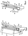
- Figure 8 is another partial cross-sectional side elevational view of the gas exchange chamber of Figure 6;
- Figure 9 is a partial cross-sectional elevational view of a press station of the apparatus of Figure of Figure 1 taken along line 9-9;
- Figure 10A is a partial perspective view of a resilient member In accordance with the invention in a fully expanded condition;
- Figure 10B is a partial perspective view of the resilient member of Figure 10A in a compressed condition;
- Figure 11A is a perspective view of another resilient member in accordance with the invention In a fully expanded condition; and
- Figure 11B is a perspective view of the resilient member of Figure 11A in a compressed condition.
-
- Figure 1 depicts an
apparatus 10 in accordance with the invention for assembling a small number of custom glass assemblies which may not have uniform sizes or shapes, and filling the glass assemblies with an insulating gas. The apparatus includes a lay-up station 50, agas exchange chamber 60, apress station 80 and a lay-down station 100. - The lay-
up station 50 includes aframe 51 which rests on a number oflegs 52. A plurality offirst rollers 53 are positioned at the bottom of theframe 51 and each roller is rotated about an axis that is inclined at an acute angle relative to the horizontal axis x. A plurality ofsecond rollers 54 are positioned at an acute angle relative to the vertical axis y and rotated about an axis that is substantially normal to the axis of rotation of thefirst rollers 53. Thesecond rollers 54 are generally elongated rods that extend from just above thefirst rollers 53 to the top of theframe 51, and eachroller 54 may have a number ofprotective bands 55 positioned circumferentially about the exterior of the roller at intervals along its length. Theprotective bands 55 may be made from rubber or other shock absorbing materials that have a sufficiently high coefficient of friction to allow apane 21 to rotate therollers 54 as it is translated to thegas exchange chamber 60. - The
gas exchange chamber 60 is positioned immediately down-line from the lay-up station 50, and thepress station 80 is positioned immediately down-line from thegas exchange chamber 60. In Figure 1, thegas exchange chamber 60 andpress station 80 are viewed from the front which shows theplaten wall 61 of thegas exchange chamber 60 and thepress plates 90 andactuators 91 of thepress station 80. - The lay-
down station 100 is down-line from thepress station 80. The lay-down station is similar to the lay-up station 50, in that it has a plurality offirst rollers 103 andsecond rollers 104 that are positioned the same as theroller up station 50, thesecond rollers 104 of the lay-down station 100 may also have a number ofprotective bands 105 of shock absorbing material positioned circumferentially around therollers 104 along their length. The lay-down station 100 also includes apivoting frame 101 which may be rotated so that thesecond rollers 104 define a plane which is generally parallel to the plane defined by the horizontal axis x. - Figure 2 is a front elevation view of the
apparatus 10 showing the fixed structure of thegas exchange chamber 60 and thepress station 80 without theplaten wall 61 or thepress plates 90. Threeglass assemblies 20, 20' and 20'' of different sizes and shapes are shown initially resting on thefirst rollers 53 and thesecond roller 54 in a partly assembled state. The glass assemblies may be easily moved from the lay-up station 50 to thegas exchange chamber 60 by first rolling the assemblies along therollers rollers 63 andsupport surface 64 of thegas exchanger 60. Therollers 63 are rotated about an axis that inclined at an angle to the horizontal axis x, which Is preferably the same angle of inclination as that of therollers 53. Thesupport surface 64 is inclined at an angle relative to the vertical axis y and is positioned substantially normal to the axis about which theroller 63 rotate. - A number of
orifices 65 are positioned through the support surface for directing pressurized air through thesupport surface 64 to provide an air bearing upon which theglass assemblies 20, 20' and 20'' may be translated while they are in thegas exchange chamber 60. The orifices may be separately connected to individual air lines, or they may be positioned on a wall of a plenum chamber. - The fixed structure of the
press station 80 is similar to that of thegas exchange chamber 60. The glass assemblies may be easily moved from thegas exchange chamber 60 to thepress station 80 by moving the assemblies along therollers 63 andsupport surface 64 of thegas exchanger 60 until they reach therollers 83 andsupport surface 84 of thepress station 80. Therollers 83 are also rotated about an axis that is inclined at an angle to the horizontal axis x, which is preferably the same angle of inclination as that of therollers support surface 84 is inclined at an angle relative to the vertical axis y and is positioned substantially normal to the axis about which theroller 83 rotate. - A number of
orifices 85 are positioned through thesupport surface 84 for directing pressurized air through thesupport surface 84 to provide an air bearing upon which theglass assemblies 20, 20' and 20'' may be translated while they are in thepress station 80. Theorifices 85 may be separately connected to individual air lines, or they may be positioned on a wall of a plenum chamber. - Figure 3 depicts another front elevational view of the
apparatus 10 in which theplaten wall 61 and thepress plates 90 are positioned with respect to their fixed structures. Thegas exchange chamber 60 further includes apressurized gas supply 68 and a vacuum pump 66. When thegas exchange chamber 60 is closed and sealed, air is removed by activating the vacuum pump 66 andopening valve 67. After substantially all of the air is removed from within thegas exchange chamber 60,valve 67 is closed andvalve 69 is opened so that a pressurized gas having an thermal conductivity that is less than that of air is forced into the gas exchange chamber. In a preferred embodiment, a vacuum of about 0.01 - 0.05 atmospheric pressure is drawn within thegas exchange chamber 60 and the insulating gas is fed into the chamber until the pressure within the chamber is between 0 - 2 psi. - The method and operation of a preferred embodiment of the invention are best shown in Figures 4-10A and 10B. Figure 4 is a cross-sectional side elevation view of a
first pane 21 of glass positioned on therollers up station 50. Thepane 21 has aninterior surface 22, anexterior surface 23, abottom edge 24 and atop portion 25. Therollers 53 supportively abut thebottom edge 24 and theprotective bands 55 supportively abut theexterior surface 23. As best shown in Figure 4, the axis about which theroller 53 rotate is positioned at an acute angle α with respect to the horizontal axis x and therollers 54 rotate about an axis that is substantially normal to the axis of rotation of therollers 53. - Figure 5 is a cross-sectional side elevation view of a partly assembled
glass assembly 20 positioned on therollers up station 50. Aspacer 31 with an adhesive 34 spread in a thin layers on first andsecond sides first side 32 to theinterior surface 22 of the first pane. The adhesive 34 is preferably polyisobutelyne, but other adhesives may be used. Asecond pane 26, which has a interior surface 27, anexterior surface 28,bottom edge 29 and atop portion 30 is positioned in a partly assembled state on therollers 53. Thesecond pane 26 is positioned on the lay-up station 50 so as to contact the adhesive 34 on thesecond side 33 of thespacer 31 only on a portion of the interior surface 27 that is just above thebottom edge 29. Additional portions of the interior surface 27 of thesecond pane 26 are prevented from contacting the adhesive 34 on thesecond side 33 of thespacer 31 by positioning aresilient member 40 in a corner of the partly assembledglass assembly 20 between thetop portion 30 of the interior surface 27 of thesecond pane 26 and thetop portion 25 of theinterior surface 22 offirst pane 21. By positioning theresilient member 40 between the first and second panes, agap 49 is created between thesecond side 33 of thespacer 31 and the Interior surface 27 of thesecond pane 26 along three legs of the spacer. - The
resilient member 40 may be a rectilinear cube of foam, a spring or a C-shaped plastic member that buckles under added pressure. Theresilient member 40 has a sufficient load deflection factor to maintain thegap 49 between the panes until the interior surface 27 of thesecond pane 25 is pressed against the adhesive 34 on thesecond side 33 of thespacer 31. Yet, the load deflection factor of theresilient member 40 is low enough that the resilient member will not separate the interior surface 27 of thesecond pane 26 from the adhesive 34 on thesecond side 33 of the spacer under the load of thesecond pane 26 and the bonding friction of the adhesive 34. - The load deflection factor of the
resilient member 40 necessary to operate the method and apparatus of the invention vary depending upon the angle at which the glass assemblies are inclined, the mass of the panes and the adhesiveness of the adhesive. Accordingly, differentresilient members 40 may be necessary to effectively operate the invention in light of the number of different sizes and shapes of custom glass assemblies. - Referring to Figures 6 and 7, a partly assembled
glass assembly 20 is shown positioned In thegas exchange chamber 60. Theplaten wall 61 is pivoted about abracket 74 by anactuator 73 andlink assembly 72 between an open position as shown in Figure 6 and a closed position as shown in Figure 7. When theplaten wall 61 is in the open position, air may be forced through theorifices 65 in thesupport surface 64 to create andair bearing 78. A partly assembledglass assembly 20 may be translated on theair bearing 78 over thesupport surface 64 until it is positioned opposite aplaten 70. - After the partly assembled
glass assembly 20 is appropriately positioned opposite aplaten 70 within thegas chamber 60, theplaten wall 61 is closed to seal the gas exchange chamber as shown in Figure 7. Air is then removed from within the sealed gas exchange chamber and an insulating gas is bled into the chamber as described above. As the vacuum is drawn in thegas exchange chamber 60, air is also removed from within the interpane space 36 of theglass assembly 20 through thegap 49. Similarly, as the insulating gas is bled back into thegas exchange chamber 60, the insulating gas passes through thegap 49 and fills the interpane space 36. The pressure of the insulating gas in the chamber, and thus the interpane space 36 as well, may be varied from 0-2 psi in order to ensure that the interpane space is adequately filled with the insulating gas and to obtain a desired distance between the panes. It will be appreciated that the distance between the panes under atmospheric conditions may be increased by pressurizing the gas in the interpane space to above atmospheric pressure before thegap 49 is closed. Accordingly, the distance between the panes of the glass assembly may be adjusted by pressurizing the interpane pace 36 with the insulating gas to a predetermined pressure. - Referring to Figure 8, after the
interpane space 26 has been filled with an insulating gas, it is sealed by driving theplaten 70 against theexterior surface 28 of thesecond pane 26. As theplaten 70 drives thesecond pane 26, the second pane compresses theresilient member 40 until thetop portion 30 of the interior surface 27 contacts and compresses the adhesive 34 on thesecond side 33 of thespacer 31. In order to adequately seal and adhere the interior surface 27 to the adhesive 34, the second pane should be driven until the adhesive is approximately 0.015 to 0.020 inches thick. The interpane space 36 is sealed from the outer environment once the interior surface 27 of the second pane sufficiently compresses the adhesive 34, and the seal is maintained after theplaten 70 is removed from thesecond pane 26 since the compressedresilient member 40 is not so resilient as to overcome the weight of thesecond pane 26 and the bonding friction of the adhesive 34. - The
platen 70 may be driven by one or morehydraulic actuators 71. Thegas exchange chamber 60 generally has a number of individuallyoperable platens 70, each of which engages only asingle glass assembly 20. By having a number of individually controlledplatens 70, several differentcustom glass assemblies 20, 20' and 20'' may be partly assembled on the lay-up station 50 and then simultaneously filled with an insulating gas in a single cycle. - Referring to Figure 9, a gas filled
glass assembly 20 is shown positioned in thepress station 80. One of thelinear actuators 91 is shown attached to thepress plate 90 in Figure 9, but in a preferred embodiment a linear actuator is positioned in each corner of thepress plate 90 as shown in Figures 1 and 3. Eachlinear actuator 91 is attached to the frame of the press station by at least onebracket 92. The linear actuators may be hydraulic cylinders, pneumatic cylinders, electric servo-motors or any other type of actuator that can linearly drive a rod a precise distance. Thelinear actuators 91 move thepress plates 90 in a direction which is parallel to the longitudinal axis of the actuators and substantially normal to thesupport surface 84. - In operation, a sealed
glass assembly 20 is positioned opposite apress plate 90 in thepress station 80 on an air bearing in the same manner that a partially assembled glass assembly is positioned opposite aplaten 70 in thegas exchange chamber 60. Once a glass assembly is properly positioned, thelinear actuators 91 drive thepress plate 90 against the exterior surface of thesecond pane 26 to further compress the adhesive 34 until it is about 0.010 inches thick. The purpose of thepress assembly 80 is to more accurately compress the panes and adhesive together to form a thin, uniform layer of adhesive 34 around the full length of thespacer 31. Accordingly, it is important that theactuators 91 be able to precisely control the distance that thepress plate 90 is driven. - The positioning and use of the
resilient member 40 is better understood by referring to Figures 10A and 10B. Figure 10A shows a foamresilient member 40 fully expanded so that thegap 49 is formed between the interior surface of thesecond pane 26 and the adhesive 34 on the second side of thespacer 31. After thesecond pane 26 is driven against the adhesive 34 as described above, theresilient member 40 is compressed between thepanes intermediate portion 41 as shown In Figure 10B. The resilient member may be removed as shown by the arrow in Figure 10B anytime after theglass assembly 20 is removed from thegas exchange chamber 60. - Figures 11A and 11B depict another
resilient member 40 in accordance with the invention which is C-shaped is cross-section. The C-shapedresilient member 40 has aback sections 44, a first leg 4 and asecond leg 46. Afurrow 47 runs longitudinally along the inner face of theback section 44. In operation, the outer face of thefirst leg 45 contacts the interior surface of one of the panes and the outer surface of thesecond leg 46 contacts the interior surface of the other pane. When theresilient member 40 is fully expanded as shown if Figure 11A, the width of the back section 44 (the distance between the first and second legs) is sufficient to create and maintain the gap as described above. As the panes are driven towards each other, the C-shapedresilient member 40 buckles along thefurrow 47 as shown in Figure 11B. Theresilient member 40 may then be removed by simply pulling it out from between the panes.
Claims (11)
- A method of assembling custom multi-pane glass assemblies such as sealed double glazing units, in which a spacer (31) having sealant (34) on opposing surfaces (32,33) thereof is adhered to a first glass pane (21), a member (40) is positioned alongside a portion of the spacer (31), a second glass pane (26) is positioned over the spacer (31) so that it is partially adhered to the spacer (31) to define an interpane space (36) around which the spacer (31) is adhered, but with the member (40) preventing contact with the whole of the spacer (31) so maintaining a gap between a portion of the spacer (31) and the second glass pane (26), the resulting assembly is moved into a gas exchange chamber (60), air is removed from the chamber and accordingly also the interpane space (36), and a gas having a coefficient of thermal conductivity lower than that of air is introduced into the chamber and accordingly also the interpane space (36), characterised in that the member (40) is resilient, and in that the glass panes (21,26) are pressed together while in the gas exchange chamber to compress the resilient member (40) and adhere the second glass pane (26) to all of the spacer (31)to seal the interpane space (36).
- A method as claimed in Claim 1 further comprising the step of compressing the glass panes (21,26) and spacer (31) together to a precise thickness.
- A method as claimed in Claim 1 or Claim 2 further comprising removing the compressed resilient member and applying a sealant across at least a portion of the width of the spacer (31) around the perimeter thereof.
- A method as claimed in any preceding claim in which the glass panes (21,26) are laid at an angle to the upright and are supported at their lower ends on roller means (53) to allow movement of the assembly into the gas exchange chamber (60).
- A method as claimed in any preceding claim in which the glass panes are pressed together by a platen (70) which is moved by a plurality of hydraulic cylinders (71).
- A method as claimed in Claim 5 in which the platen (70) is rectilinear and moved by four hydraulic cylinders (71), one cylinder operatively attached to each corner area of the platen.
- A method as claimed in any preceding claim which further comprises a press station (80) positioned after the gas exchange chamber (50), the press station (80) including roller means (83) and a support surface (84) to receive the glass assembly from the gas exchange chamber (50) and a press plate (90) positioned opposite the support surface (84), means (91) for moving the plate (90) toward the second pane (26) for further compressing the panes (21,26) and the spacer (31) together to a precise thickness.
- Apparatus for assembling custom multi-pane glass assemblies such as sealed double glazing units, from a partial assembly comprising a first glass panel (21) a spacer (31) having sealant (34) on opposing surfaces (32,33) thereof being adhered to said first glass pane (21) to define an interpane space (36) around which the spacer (31) is adhered, a member (40) positioned alongside a portion of that spacer (31) outside the interpane space (36) and a second glass pane (26) positioned over the spacer with its lower edge supported by roller means (53) so that the second glass pane (26) is partially adhered to the spacer (31) but with the member (40) preventing contact with the whole of the spacer (31) so maintaining a gap between a portion of the spacer (31) and the second glass pane (26), said apparatus comprising a lay-up system (50) having roller means (35,54) onto which the first glass pane (21) is laid to support it during adhesion of the spacer (31) to said first glass pane, the member (40) is positioned alongside said portion of of the spacer (31) and the second glass pane (26) is positioned over the spacer and which transport the resulting partially assembled glass assembly from the lay-up station (50), a gas exchange chamber (60) into which the resulting assembly is moved from the lay-up station (50), means (66) for removing air from the chamber (60), and means (68) for introducing a gas having a coefficient of thermal conductivity lower than that of air into the chamber (60), characterised in that the member (40) is resilient and in that a platen (70) is provided in the gas chamber (60), and in that means are provided for moving that platen (70) against the second glass pane (26) to compress the resilient member (40) and adhere the second glass pane (26) to all of the spacer (31) to seal the interpane space (36).
- The apparatus of Claim 8, wherein the platen (70) is moved by a plurality of hydraulic cylinders (71).
- The apparatus of Claim 9, wherein the platen (70) is rectilinear and moved by four hydraulic cylinders (71), one cylinder operatively attached to each corner area of the platen.
- The apparatus of any of Claims 8 to 9, further comprising a press station (80) positioned after the gas exchange chamber (50), the press station (80) including roller means (83) and a support surface (84) to receive the glass assembly from the gas exchange chamber (50) and a press plate (90) positioned opposite the support surface (84), means (91) for moving the plate (90) toward the second pane (26) for further compressing the panes (21,26) and the spacer (31) together to a precise thickness.
Applications Claiming Priority (3)
| Application Number | Priority Date | Filing Date | Title |
|---|---|---|---|
| US363250 | 1994-12-23 | ||
| US08/363,250 US5573618A (en) | 1994-12-23 | 1994-12-23 | Method for assembling custom glass assemblies |
| PCT/US1995/007050 WO1996020328A1 (en) | 1994-12-23 | 1995-06-02 | Method and apparatus for assembling custom glass assemblies |
Publications (2)
| Publication Number | Publication Date |
|---|---|
| EP0799362A1 EP0799362A1 (en) | 1997-10-08 |
| EP0799362B1 true EP0799362B1 (en) | 2000-08-16 |
Family
ID=23429454
Family Applications (1)
| Application Number | Title | Priority Date | Filing Date |
|---|---|---|---|
| EP95921595A Expired - Lifetime EP0799362B1 (en) | 1994-12-23 | 1995-06-02 | Method and apparatus for assembling custom glass assemblies |
Country Status (16)
| Country | Link |
|---|---|
| US (2) | US5573618A (en) |
| EP (1) | EP0799362B1 (en) |
| JP (1) | JP3581154B2 (en) |
| AT (1) | ATE195576T1 (en) |
| AU (1) | AU2661995A (en) |
| CA (1) | CA2207843C (en) |
| DE (1) | DE69518440T2 (en) |
| DK (1) | DK0799362T3 (en) |
| ES (1) | ES2151068T3 (en) |
| FI (1) | FI972668A (en) |
| GR (1) | GR3034864T3 (en) |
| MX (1) | MX9704730A (en) |
| NO (1) | NO311775B1 (en) |
| PL (1) | PL179736B1 (en) |
| PT (1) | PT799362E (en) |
| WO (1) | WO1996020328A1 (en) |
Cited By (1)
| Publication number | Priority date | Publication date | Assignee | Title |
|---|---|---|---|---|
| US8905085B2 (en) | 2011-09-09 | 2014-12-09 | Erdman Automation Corporation | Apparatus for edge sealing and simultaneous gas filling of insulated glass units |
Families Citing this family (36)
| Publication number | Priority date | Publication date | Assignee | Title |
|---|---|---|---|---|
| US5957169A (en) * | 1997-10-24 | 1999-09-28 | Cardinal Ig Company | Apparatus and method for filling insulated glass units with insulating gas |
| US6216751B1 (en) | 1997-10-24 | 2001-04-17 | Cardinal Ig Company | Method of reliably detecting seal failures |
| US6326067B1 (en) | 1999-05-03 | 2001-12-04 | Guardian Industries Corporation | Vacuum IG pillar with DLC coating |
| US6365242B1 (en) | 1999-07-07 | 2002-04-02 | Guardian Industries Corp. | Peripheral seal for vacuum IG window unit |
| US6916392B2 (en) * | 2001-06-21 | 2005-07-12 | Cardinal Ig Company | Producing and servicing insulating glass units |
| US20030047538A1 (en) * | 2001-09-12 | 2003-03-13 | Paul Trpkovski | Laser etching indicia apparatus |
| US6606837B2 (en) | 2001-08-28 | 2003-08-19 | Cardinal Ig | Methods and devices for simultaneous application of end sealant and sash sealant |
| US6804924B2 (en) | 2001-10-12 | 2004-10-19 | Cardinal Ig Company | Repair of insulating glass units |
| US6793971B2 (en) * | 2001-12-03 | 2004-09-21 | Cardinal Ig Company | Methods and devices for manufacturing insulating glass units |
| US7167767B2 (en) * | 2003-08-22 | 2007-01-23 | Ged Integrated Solutions, Inc. | Glass production sequencing |
| DE102004009858B4 (en) * | 2004-02-25 | 2006-05-04 | Karl Lenhardt | Method for positioning glass sheets in a vertical assembly and pressing device for insulating glass panes |
| GB2432871B (en) * | 2005-11-21 | 2010-04-07 | Denis Augustine Carey | A Process for Producing Double Glazed Glass Panels |
| US8967219B2 (en) | 2010-06-10 | 2015-03-03 | Guardian Ig, Llc | Window spacer applicator |
| WO2009064905A1 (en) | 2007-11-13 | 2009-05-22 | Infinite Edge Technologies, Llc | Sealed unit and spacer |
| US9309714B2 (en) | 2007-11-13 | 2016-04-12 | Guardian Ig, Llc | Rotating spacer applicator for window assembly |
| US20110120049A1 (en) * | 2008-01-08 | 2011-05-26 | Ano Leo | Prefabricated Building Components and Assembly Equipment |
| US20090173037A1 (en) * | 2008-01-08 | 2009-07-09 | Ano Leo | Prefabricated Building Components and Assembly Equipments |
| PL220133B1 (en) | 2008-04-14 | 2015-08-31 | Ireneusz Rabczak | Method for improvement of functional parameters of objects equipped with combined transparent elements and the electronic system to use that method |
| US8726487B2 (en) | 2009-05-12 | 2014-05-20 | Ged Integrated Solutions, Inc. | Efficient assembly of double or triple pane windows |
| US8813337B2 (en) | 2009-05-12 | 2014-08-26 | Ged Integrated Solutions, Inc. | Efficient assembly of insulating glass windows |
| US8586193B2 (en) | 2009-07-14 | 2013-11-19 | Infinite Edge Technologies, Llc | Stretched strips for spacer and sealed unit |
| US8381382B2 (en) * | 2009-12-31 | 2013-02-26 | Cardinal Ig Company | Methods and equipment for assembling triple-pane insulating glass units |
| US8627856B2 (en) | 2010-06-28 | 2014-01-14 | Integrated Automation Systems, Llc | Continuous gas filling process and apparatus for fabrication of insulating glass units |
| US9228389B2 (en) | 2010-12-17 | 2016-01-05 | Guardian Ig, Llc | Triple pane window spacer, window assembly and methods for manufacturing same |
| US9260907B2 (en) | 2012-10-22 | 2016-02-16 | Guardian Ig, Llc | Triple pane window spacer having a sunken intermediate pane |
| US9689196B2 (en) | 2012-10-22 | 2017-06-27 | Guardian Ig, Llc | Assembly equipment line and method for windows |
| US9656356B2 (en) | 2013-01-22 | 2017-05-23 | Guardian Ig, Llc | Window unit assembly station and method |
| US9784027B2 (en) | 2013-12-31 | 2017-10-10 | Guardian Glass, LLC | Vacuum insulating glass (VIG) unit with metallic peripheral edge seal and/or methods of making the same |
| US10113354B2 (en) | 2013-12-31 | 2018-10-30 | Cardinal Ig Company | Multiple-pane insulating glazing unit assembly, gas filling, and pressing machine |
| US10280680B2 (en) | 2013-12-31 | 2019-05-07 | Guardian Glass, LLC | Vacuum insulating glass (VIG) unit with pump-out port sealed using metal solder seal, and/or method of making the same |
| US10012019B2 (en) | 2013-12-31 | 2018-07-03 | Guardian Glass, LLC | Vacuum insulating glass (VIG) unit with metallic peripheral edge seal and/or methods of making the same |
| US10145005B2 (en) | 2015-08-19 | 2018-12-04 | Guardian Glass, LLC | Techniques for low temperature direct graphene growth on glass |
| US10968685B2 (en) * | 2016-01-04 | 2021-04-06 | PDS IG Holding LLC | Gas filling of an insulating glass unit |
| US10253552B2 (en) * | 2016-04-21 | 2019-04-09 | Erdman Automation Corporation | High speed parallel process insulated glass manufacturing line |
| US11187028B2 (en) | 2017-07-01 | 2021-11-30 | PDSD IG Holding LLC | Filling and sealing device and method for an insulated glass unit |
| CN114541935B (en) * | 2022-02-21 | 2024-02-02 | 东莞市明达玻璃有限公司 | Hollow glass processing production line |
Family Cites Families (12)
| Publication number | Priority date | Publication date | Assignee | Title |
|---|---|---|---|---|
| CH627720A5 (en) * | 1977-05-16 | 1982-01-29 | Glasmatec Ag | DEVICE FOR THE PRODUCTION OF AN INSULATING GLASS DISC AND USE THEREOF. |
| DE3101342C2 (en) * | 1981-01-17 | 1984-08-02 | Vereinigte Glaswerke Gmbh, 5100 Aachen | "Process for the production of gas-filled insulating glass units and device for carrying out the process" |
| AT368985B (en) * | 1981-05-26 | 1982-11-25 | Lisec Peter | DEVICE FOR FILLING INSULATING GLASS WITH HEAVY GAS |
| US4780164A (en) * | 1986-11-20 | 1988-10-25 | Cardinal Ig Company | Method for producing gas-containing insulating glass assemblies |
| US4950344A (en) * | 1988-12-05 | 1990-08-21 | Lauren Manufacturing Company | Method of manufacturing multiple-pane sealed glazing units |
| US5017252A (en) * | 1988-12-06 | 1991-05-21 | Interpane Coatings, Inc. | Method for fabricating insulating glass assemblies |
| US5106663A (en) * | 1989-03-07 | 1992-04-21 | Tremco Incorporated | Double-paned window system having controlled sealant thickness |
| US5080146A (en) * | 1989-03-20 | 1992-01-14 | The United States Of America As Represented By The United States Department Of Energy | Method and apparatus for filling thermal insulating systems |
| DK173809B1 (en) * | 1989-03-30 | 2001-11-12 | Cardinal Ig Co | Process for the preparation of gas-filled thermal glass panes |
| FR2648179B1 (en) * | 1989-06-12 | 1991-09-20 | Pont Audemer Vitrages Isolants | METHOD AND MACHINE FOR AUTOMATICALLY LAYING INSERTION JOINTS BETWEEN THE ELEMENTS OF A MULTIPLE GLAZING |
| DE4022185A1 (en) * | 1990-07-13 | 1992-01-16 | Lenhardt Maschinenbau | METHOD AND DEVICE FOR ASSEMBLING INSULATING GLASS PANELS FILLED WITH A GAS DIFFERENT FROM AIR |
| US5139595A (en) * | 1990-07-16 | 1992-08-18 | Taylor Donald M | Gas filling system for glazing panels |
-
1994
- 1994-12-23 US US08/363,250 patent/US5573618A/en not_active Expired - Lifetime
-
1995
- 1995-06-02 WO PCT/US1995/007050 patent/WO1996020328A1/en active IP Right Grant
- 1995-06-02 DE DE69518440T patent/DE69518440T2/en not_active Expired - Lifetime
- 1995-06-02 AU AU26619/95A patent/AU2661995A/en not_active Abandoned
- 1995-06-02 CA CA002207843A patent/CA2207843C/en not_active Expired - Lifetime
- 1995-06-02 JP JP52042496A patent/JP3581154B2/en not_active Expired - Lifetime
- 1995-06-02 DK DK95921595T patent/DK0799362T3/en active
- 1995-06-02 AT AT95921595T patent/ATE195576T1/en not_active IP Right Cessation
- 1995-06-02 EP EP95921595A patent/EP0799362B1/en not_active Expired - Lifetime
- 1995-06-02 PL PL95320920A patent/PL179736B1/en not_active IP Right Cessation
- 1995-06-02 MX MX9704730A patent/MX9704730A/en not_active IP Right Cessation
- 1995-06-02 PT PT95921595T patent/PT799362E/en unknown
- 1995-06-02 ES ES95921595T patent/ES2151068T3/en not_active Expired - Lifetime
-
1996
- 1996-11-08 US US08/747,072 patent/US5753069A/en not_active Expired - Fee Related
-
1997
- 1997-06-19 FI FI972668A patent/FI972668A/en not_active Application Discontinuation
- 1997-06-20 NO NO19972902A patent/NO311775B1/en unknown
-
2000
- 2000-11-16 GR GR20000402553T patent/GR3034864T3/en not_active IP Right Cessation
Cited By (1)
| Publication number | Priority date | Publication date | Assignee | Title |
|---|---|---|---|---|
| US8905085B2 (en) | 2011-09-09 | 2014-12-09 | Erdman Automation Corporation | Apparatus for edge sealing and simultaneous gas filling of insulated glass units |
Also Published As
| Publication number | Publication date |
|---|---|
| US5573618A (en) | 1996-11-12 |
| DK0799362T3 (en) | 2000-12-27 |
| FI972668A (en) | 1997-08-25 |
| PL179736B1 (en) | 2000-10-31 |
| CA2207843C (en) | 2000-08-29 |
| ATE195576T1 (en) | 2000-09-15 |
| DE69518440D1 (en) | 2000-09-21 |
| NO972902D0 (en) | 1997-06-20 |
| WO1996020328A1 (en) | 1996-07-04 |
| FI972668A0 (en) | 1997-06-19 |
| ES2151068T3 (en) | 2000-12-16 |
| PT799362E (en) | 2001-01-31 |
| NO972902L (en) | 1997-08-20 |
| US5753069A (en) | 1998-05-19 |
| NO311775B1 (en) | 2002-01-21 |
| JP3581154B2 (en) | 2004-10-27 |
| AU2661995A (en) | 1996-07-19 |
| MX9704730A (en) | 1997-10-31 |
| GR3034864T3 (en) | 2001-02-28 |
| PL320920A1 (en) | 1997-11-10 |
| DE69518440T2 (en) | 2001-03-29 |
| JPH10511337A (en) | 1998-11-04 |
| CA2207843A1 (en) | 1996-07-04 |
| EP0799362A1 (en) | 1997-10-08 |
Similar Documents
| Publication | Publication Date | Title |
|---|---|---|
| EP0799362B1 (en) | Method and apparatus for assembling custom glass assemblies | |
| US5087187A (en) | Apparatus for molding hollow composite articles having internal reinforcement structures | |
| US7097724B2 (en) | Assembly of insulating glass structures on an integrated sash | |
| EP0269194B1 (en) | Method and apparatus for producing gas-containing insulating glass assemblies | |
| CN103109031B (en) | Method for producing gas-filled triple glazing | |
| US4909874A (en) | Method and apparatus for producing gas-containing insulating glass assemblies | |
| US20090301637A1 (en) | Spacer assembly for insulating glazing unit and method for assembling an insulating glazing unit | |
| JP2001520975A (en) | Apparatus and method for filling insulating glass unit with insulating gas | |
| US8632648B2 (en) | Method and device for the assembly of insulating glass panes that are filled with a gas different from air | |
| DE102013204338A1 (en) | Apparatus and method for making composite panels using a reusable vacuum bag | |
| US3972766A (en) | Apparatus for fabricating flat objects | |
| CA2392276A1 (en) | Method of reliably detecting seal failures | |
| JPH02267141A (en) | Prepation of multi-layered insulation glass unit | |
| CN113002039B (en) | Novel plate pressing type laminating machine and pressing method for laminated plate-shaped piece | |
| AT506120A1 (en) | Heating or cooling device for e.g. photo-voltaic elements, has pressure plate arrangement provided at side of elastic membrane such that elements are arranged between arrangement and heating plate, where side faces plate | |
| CN216466741U (en) | Aluminum honeycomb panel pressing plate mechanism | |
| EP0226303B1 (en) | Laminating press | |
| CN216780123U (en) | Production of honeycomb aluminum plate is with beating rubber coating machine and is constructed | |
| CN220548802U (en) | Anti-overflow mould is used in doubling glass processing | |
| CN218004889U (en) | Laminating production device | |
| CN113997678A (en) | Continuous production line and production process of aluminum honeycomb panel | |
| JP2872287B2 (en) | Method and apparatus for bonding laminated glass | |
| CN215320776U (en) | Continuous paving and aligning tool for composite material | |
| CA3193877A1 (en) | Apparatus and method for filling insulating glass with gas | |
| JPH0921988A (en) | Method for sticking liquid crystal cell and device therefor |
Legal Events
| Date | Code | Title | Description |
|---|---|---|---|
| PUAI | Public reference made under article 153(3) epc to a published international application that has entered the european phase |
Free format text: ORIGINAL CODE: 0009012 |
|
| 17P | Request for examination filed |
Effective date: 19970723 |
|
| AK | Designated contracting states |
Kind code of ref document: A1 Designated state(s): AT BE CH DE DK ES FR GB GR IE IT LI LU MC NL PT SE |
|
| 17Q | First examination report despatched |
Effective date: 19971114 |
|
| GRAG | Despatch of communication of intention to grant |
Free format text: ORIGINAL CODE: EPIDOS AGRA |
|
| GRAG | Despatch of communication of intention to grant |
Free format text: ORIGINAL CODE: EPIDOS AGRA |
|
| GRAG | Despatch of communication of intention to grant |
Free format text: ORIGINAL CODE: EPIDOS AGRA |
|
| GRAH | Despatch of communication of intention to grant a patent |
Free format text: ORIGINAL CODE: EPIDOS IGRA |
|
| GRAH | Despatch of communication of intention to grant a patent |
Free format text: ORIGINAL CODE: EPIDOS IGRA |
|
| EUG | Se: european patent has lapsed | ||
| GRAA | (expected) grant |
Free format text: ORIGINAL CODE: 0009210 |
|
| AK | Designated contracting states |
Kind code of ref document: B1 Designated state(s): AT BE CH DE DK ES FR GB GR IE IT LI LU MC NL PT SE |
|
| REF | Corresponds to: |
Ref document number: 195576 Country of ref document: AT Date of ref document: 20000915 Kind code of ref document: T |
|
| REG | Reference to a national code |
Ref country code: CH Ref legal event code: EP |
|
| REG | Reference to a national code |
Ref country code: IE Ref legal event code: FG4D |
|
| REF | Corresponds to: |
Ref document number: 69518440 Country of ref document: DE Date of ref document: 20000921 |
|
| ITF | It: translation for a ep patent filed |
Owner name: ING. A. GIAMBROCONO & C. S.R.L. |
|
| ET | Fr: translation filed | ||
| REG | Reference to a national code |
Ref country code: CH Ref legal event code: NV Representative=s name: E. BLUM & CO. PATENTANWAELTE |
|
| REG | Reference to a national code |
Ref country code: ES Ref legal event code: FG2A Ref document number: 2151068 Country of ref document: ES Kind code of ref document: T3 |
|
| REG | Reference to a national code |
Ref country code: DK Ref legal event code: T3 |
|
| REG | Reference to a national code |
Ref country code: PT Ref legal event code: SC4A Free format text: AVAILABILITY OF NATIONAL TRANSLATION Effective date: 20001031 |
|
| PLBE | No opposition filed within time limit |
Free format text: ORIGINAL CODE: 0009261 |
|
| STAA | Information on the status of an ep patent application or granted ep patent |
Free format text: STATUS: NO OPPOSITION FILED WITHIN TIME LIMIT |
|
| 26N | No opposition filed | ||
| REG | Reference to a national code |
Ref country code: GB Ref legal event code: IF02 |
|
| REG | Reference to a national code |
Ref country code: CH Ref legal event code: PFA Free format text: CARDINAL IG COMPANY,12301 WHITEWATER DRIVE,MINNETONKA, MN 55343-9447 (US) TRANSFER- CARDINAL IG COMPANY,SUITE 200 775 PRAIRIE CENTER DRIVE,EDEN PRAIRIE/MN 55344 (US) |
|
| REG | Reference to a national code |
Ref country code: PT Ref legal event code: TE4A Free format text: CARDINAL IG COMPANY US Effective date: 20020605 |
|
| NLS | Nl: assignments of ep-patents |
Owner name: CARDINAL GLASS INDUSTRIES INC. Owner name: CARDINAL CG COMPANY |
|
| NLS | Nl: assignments of ep-patents |
Owner name: CARDINAL IG COMPANY |
|
| REG | Reference to a national code |
Ref country code: FR Ref legal event code: CA |
|
| PGFP | Annual fee paid to national office [announced via postgrant information from national office to epo] |
Ref country code: GR Payment date: 20060511 Year of fee payment: 12 |
|
| PGFP | Annual fee paid to national office [announced via postgrant information from national office to epo] |
Ref country code: MC Payment date: 20060526 Year of fee payment: 12 |
|
| PGFP | Annual fee paid to national office [announced via postgrant information from national office to epo] |
Ref country code: GB Payment date: 20060531 Year of fee payment: 12 |
|
| PGFP | Annual fee paid to national office [announced via postgrant information from national office to epo] |
Ref country code: LU Payment date: 20060601 Year of fee payment: 12 |
|
| PGFP | Annual fee paid to national office [announced via postgrant information from national office to epo] |
Ref country code: PT Payment date: 20060602 Year of fee payment: 12 |
|
| PGFP | Annual fee paid to national office [announced via postgrant information from national office to epo] |
Ref country code: NL Payment date: 20060604 Year of fee payment: 12 |
|
| PGFP | Annual fee paid to national office [announced via postgrant information from national office to epo] |
Ref country code: SE Payment date: 20060607 Year of fee payment: 12 |
|
| PGFP | Annual fee paid to national office [announced via postgrant information from national office to epo] |
Ref country code: FR Payment date: 20060608 Year of fee payment: 12 |
|
| PGFP | Annual fee paid to national office [announced via postgrant information from national office to epo] |
Ref country code: IE Payment date: 20060616 Year of fee payment: 12 |
|
| PGFP | Annual fee paid to national office [announced via postgrant information from national office to epo] |
Ref country code: IT Payment date: 20060630 Year of fee payment: 12 |
|
| PGFP | Annual fee paid to national office [announced via postgrant information from national office to epo] |
Ref country code: ES Payment date: 20060720 Year of fee payment: 12 |
|
| PGFP | Annual fee paid to national office [announced via postgrant information from national office to epo] |
Ref country code: BE Payment date: 20060816 Year of fee payment: 12 |
|
| REG | Reference to a national code |
Ref country code: CH Ref legal event code: PFA Owner name: CARDINAL IG COMPANY Free format text: CARDINAL IG COMPANY#SUITE 200 775 PRAIRIE CENTER DRIVE#EDEN PRAIRIE/MN 55344 (US) -TRANSFER TO- CARDINAL IG COMPANY#SUITE 200 775 PRAIRIE CENTER DRIVE#EDEN PRAIRIE/MN 55344 (US) |
|
| REG | Reference to a national code |
Ref country code: PT Ref legal event code: MM4A Free format text: LAPSE DUE TO NON-PAYMENT OF FEES Effective date: 20071203 |
|
| BERE | Be: lapsed |
Owner name: *CARDINAL IG CY Effective date: 20070630 |
|
| PG25 | Lapsed in a contracting state [announced via postgrant information from national office to epo] |
Ref country code: PT Free format text: LAPSE BECAUSE OF NON-PAYMENT OF DUE FEES Effective date: 20071203 Ref country code: MC Free format text: LAPSE BECAUSE OF NON-PAYMENT OF DUE FEES Effective date: 20070630 |
|
| EUG | Se: european patent has lapsed | ||
| GBPC | Gb: european patent ceased through non-payment of renewal fee |
Effective date: 20070602 |
|
| NLV4 | Nl: lapsed or anulled due to non-payment of the annual fee |
Effective date: 20080101 |
|
| REG | Reference to a national code |
Ref country code: IE Ref legal event code: MM4A |
|
| PG25 | Lapsed in a contracting state [announced via postgrant information from national office to epo] |
Ref country code: BE Free format text: LAPSE BECAUSE OF NON-PAYMENT OF DUE FEES Effective date: 20070630 |
|
| REG | Reference to a national code |
Ref country code: FR Ref legal event code: ST Effective date: 20080229 |
|
| PG25 | Lapsed in a contracting state [announced via postgrant information from national office to epo] |
Ref country code: NL Free format text: LAPSE BECAUSE OF NON-PAYMENT OF DUE FEES Effective date: 20080101 |
|
| PG25 | Lapsed in a contracting state [announced via postgrant information from national office to epo] |
Ref country code: IE Free format text: LAPSE BECAUSE OF NON-PAYMENT OF DUE FEES Effective date: 20070604 Ref country code: GB Free format text: LAPSE BECAUSE OF NON-PAYMENT OF DUE FEES Effective date: 20070602 |
|
| PG25 | Lapsed in a contracting state [announced via postgrant information from national office to epo] |
Ref country code: SE Free format text: LAPSE BECAUSE OF NON-PAYMENT OF DUE FEES Effective date: 20070603 |
|
| PGFP | Annual fee paid to national office [announced via postgrant information from national office to epo] |
Ref country code: DK Payment date: 20080612 Year of fee payment: 14 Ref country code: CH Payment date: 20080611 Year of fee payment: 14 |
|
| REG | Reference to a national code |
Ref country code: ES Ref legal event code: FD2A Effective date: 20070604 |
|
| PG25 | Lapsed in a contracting state [announced via postgrant information from national office to epo] |
Ref country code: FR Free format text: LAPSE BECAUSE OF NON-PAYMENT OF DUE FEES Effective date: 20070702 |
|
| PG25 | Lapsed in a contracting state [announced via postgrant information from national office to epo] |
Ref country code: ES Free format text: LAPSE BECAUSE OF NON-PAYMENT OF DUE FEES Effective date: 20070604 |
|
| PG25 | Lapsed in a contracting state [announced via postgrant information from national office to epo] |
Ref country code: GR Free format text: LAPSE BECAUSE OF NON-PAYMENT OF DUE FEES Effective date: 20080104 |
|
| PG25 | Lapsed in a contracting state [announced via postgrant information from national office to epo] |
Ref country code: LU Free format text: LAPSE BECAUSE OF NON-PAYMENT OF DUE FEES Effective date: 20070602 |
|
| PG25 | Lapsed in a contracting state [announced via postgrant information from national office to epo] |
Ref country code: IT Free format text: LAPSE BECAUSE OF NON-PAYMENT OF DUE FEES Effective date: 20070602 |
|
| REG | Reference to a national code |
Ref country code: CH Ref legal event code: PL |
|
| REG | Reference to a national code |
Ref country code: DK Ref legal event code: EBP |
|
| PG25 | Lapsed in a contracting state [announced via postgrant information from national office to epo] |
Ref country code: LI Free format text: LAPSE BECAUSE OF NON-PAYMENT OF DUE FEES Effective date: 20090630 Ref country code: CH Free format text: LAPSE BECAUSE OF NON-PAYMENT OF DUE FEES Effective date: 20090630 |
|
| PG25 | Lapsed in a contracting state [announced via postgrant information from national office to epo] |
Ref country code: DK Free format text: LAPSE BECAUSE OF NON-PAYMENT OF DUE FEES Effective date: 20090630 |
|
| PGFP | Annual fee paid to national office [announced via postgrant information from national office to epo] |
Ref country code: AT Payment date: 20100610 Year of fee payment: 16 |
|
| PGFP | Annual fee paid to national office [announced via postgrant information from national office to epo] |
Ref country code: DE Payment date: 20100526 Year of fee payment: 16 |
|
| PG25 | Lapsed in a contracting state [announced via postgrant information from national office to epo] |
Ref country code: AT Free format text: LAPSE BECAUSE OF NON-PAYMENT OF DUE FEES Effective date: 20110602 |
|
| REG | Reference to a national code |
Ref country code: AT Ref legal event code: MM01 Ref document number: 195576 Country of ref document: AT Kind code of ref document: T Effective date: 20110602 |
|
| REG | Reference to a national code |
Ref country code: DE Ref legal event code: R119 Ref document number: 69518440 Country of ref document: DE Effective date: 20120103 |
|
| PG25 | Lapsed in a contracting state [announced via postgrant information from national office to epo] |
Ref country code: DE Free format text: LAPSE BECAUSE OF NON-PAYMENT OF DUE FEES Effective date: 20120103 |