EP0800951A1 - Power output apparatus and method of controlling the same - Google Patents
Power output apparatus and method of controlling the same Download PDFInfo
- Publication number
- EP0800951A1 EP0800951A1 EP97103980A EP97103980A EP0800951A1 EP 0800951 A1 EP0800951 A1 EP 0800951A1 EP 97103980 A EP97103980 A EP 97103980A EP 97103980 A EP97103980 A EP 97103980A EP 0800951 A1 EP0800951 A1 EP 0800951A1
- Authority
- EP
- European Patent Office
- Prior art keywords
- motor
- rotor
- power
- engine
- output
- Prior art date
- Legal status (The legal status is an assumption and is not a legal conclusion. Google has not performed a legal analysis and makes no representation as to the accuracy of the status listed.)
- Granted
Links
Images


Classifications
-
- B—PERFORMING OPERATIONS; TRANSPORTING
- B60—VEHICLES IN GENERAL
- B60L—PROPULSION OF ELECTRICALLY-PROPELLED VEHICLES; SUPPLYING ELECTRIC POWER FOR AUXILIARY EQUIPMENT OF ELECTRICALLY-PROPELLED VEHICLES; ELECTRODYNAMIC BRAKE SYSTEMS FOR VEHICLES IN GENERAL; MAGNETIC SUSPENSION OR LEVITATION FOR VEHICLES; MONITORING OPERATING VARIABLES OF ELECTRICALLY-PROPELLED VEHICLES; ELECTRIC SAFETY DEVICES FOR ELECTRICALLY-PROPELLED VEHICLES
- B60L58/00—Methods or circuit arrangements for monitoring or controlling batteries or fuel cells, specially adapted for electric vehicles
- B60L58/10—Methods or circuit arrangements for monitoring or controlling batteries or fuel cells, specially adapted for electric vehicles for monitoring or controlling batteries
- B60L58/12—Methods or circuit arrangements for monitoring or controlling batteries or fuel cells, specially adapted for electric vehicles for monitoring or controlling batteries responding to state of charge [SoC]
- B60L58/15—Preventing overcharging
-
- B—PERFORMING OPERATIONS; TRANSPORTING
- B60—VEHICLES IN GENERAL
- B60K—ARRANGEMENT OR MOUNTING OF PROPULSION UNITS OR OF TRANSMISSIONS IN VEHICLES; ARRANGEMENT OR MOUNTING OF PLURAL DIVERSE PRIME-MOVERS IN VEHICLES; AUXILIARY DRIVES FOR VEHICLES; INSTRUMENTATION OR DASHBOARDS FOR VEHICLES; ARRANGEMENTS IN CONNECTION WITH COOLING, AIR INTAKE, GAS EXHAUST OR FUEL SUPPLY OF PROPULSION UNITS IN VEHICLES
- B60K6/00—Arrangement or mounting of plural diverse prime-movers for mutual or common propulsion, e.g. hybrid propulsion systems comprising electric motors and internal combustion engines ; Control systems therefor, i.e. systems controlling two or more prime movers, or controlling one of these prime movers and any of the transmission, drive or drive units Informative references: mechanical gearings with secondary electric drive F16H3/72; arrangements for handling mechanical energy structurally associated with the dynamo-electric machine H02K7/00; machines comprising structurally interrelated motor and generator parts H02K51/00; dynamo-electric machines not otherwise provided for in H02K see H02K99/00
- B60K6/20—Arrangement or mounting of plural diverse prime-movers for mutual or common propulsion, e.g. hybrid propulsion systems comprising electric motors and internal combustion engines ; Control systems therefor, i.e. systems controlling two or more prime movers, or controlling one of these prime movers and any of the transmission, drive or drive units Informative references: mechanical gearings with secondary electric drive F16H3/72; arrangements for handling mechanical energy structurally associated with the dynamo-electric machine H02K7/00; machines comprising structurally interrelated motor and generator parts H02K51/00; dynamo-electric machines not otherwise provided for in H02K see H02K99/00 the prime-movers consisting of electric motors and internal combustion engines, e.g. HEVs
- B60K6/22—Arrangement or mounting of plural diverse prime-movers for mutual or common propulsion, e.g. hybrid propulsion systems comprising electric motors and internal combustion engines ; Control systems therefor, i.e. systems controlling two or more prime movers, or controlling one of these prime movers and any of the transmission, drive or drive units Informative references: mechanical gearings with secondary electric drive F16H3/72; arrangements for handling mechanical energy structurally associated with the dynamo-electric machine H02K7/00; machines comprising structurally interrelated motor and generator parts H02K51/00; dynamo-electric machines not otherwise provided for in H02K see H02K99/00 the prime-movers consisting of electric motors and internal combustion engines, e.g. HEVs characterised by apparatus, components or means specially adapted for HEVs
- B60K6/26—Arrangement or mounting of plural diverse prime-movers for mutual or common propulsion, e.g. hybrid propulsion systems comprising electric motors and internal combustion engines ; Control systems therefor, i.e. systems controlling two or more prime movers, or controlling one of these prime movers and any of the transmission, drive or drive units Informative references: mechanical gearings with secondary electric drive F16H3/72; arrangements for handling mechanical energy structurally associated with the dynamo-electric machine H02K7/00; machines comprising structurally interrelated motor and generator parts H02K51/00; dynamo-electric machines not otherwise provided for in H02K see H02K99/00 the prime-movers consisting of electric motors and internal combustion engines, e.g. HEVs characterised by apparatus, components or means specially adapted for HEVs characterised by the motors or the generators
-
- B—PERFORMING OPERATIONS; TRANSPORTING
- B60—VEHICLES IN GENERAL
- B60K—ARRANGEMENT OR MOUNTING OF PROPULSION UNITS OR OF TRANSMISSIONS IN VEHICLES; ARRANGEMENT OR MOUNTING OF PLURAL DIVERSE PRIME-MOVERS IN VEHICLES; AUXILIARY DRIVES FOR VEHICLES; INSTRUMENTATION OR DASHBOARDS FOR VEHICLES; ARRANGEMENTS IN CONNECTION WITH COOLING, AIR INTAKE, GAS EXHAUST OR FUEL SUPPLY OF PROPULSION UNITS IN VEHICLES
- B60K6/00—Arrangement or mounting of plural diverse prime-movers for mutual or common propulsion, e.g. hybrid propulsion systems comprising electric motors and internal combustion engines ; Control systems therefor, i.e. systems controlling two or more prime movers, or controlling one of these prime movers and any of the transmission, drive or drive units Informative references: mechanical gearings with secondary electric drive F16H3/72; arrangements for handling mechanical energy structurally associated with the dynamo-electric machine H02K7/00; machines comprising structurally interrelated motor and generator parts H02K51/00; dynamo-electric machines not otherwise provided for in H02K see H02K99/00
- B60K6/20—Arrangement or mounting of plural diverse prime-movers for mutual or common propulsion, e.g. hybrid propulsion systems comprising electric motors and internal combustion engines ; Control systems therefor, i.e. systems controlling two or more prime movers, or controlling one of these prime movers and any of the transmission, drive or drive units Informative references: mechanical gearings with secondary electric drive F16H3/72; arrangements for handling mechanical energy structurally associated with the dynamo-electric machine H02K7/00; machines comprising structurally interrelated motor and generator parts H02K51/00; dynamo-electric machines not otherwise provided for in H02K see H02K99/00 the prime-movers consisting of electric motors and internal combustion engines, e.g. HEVs
- B60K6/22—Arrangement or mounting of plural diverse prime-movers for mutual or common propulsion, e.g. hybrid propulsion systems comprising electric motors and internal combustion engines ; Control systems therefor, i.e. systems controlling two or more prime movers, or controlling one of these prime movers and any of the transmission, drive or drive units Informative references: mechanical gearings with secondary electric drive F16H3/72; arrangements for handling mechanical energy structurally associated with the dynamo-electric machine H02K7/00; machines comprising structurally interrelated motor and generator parts H02K51/00; dynamo-electric machines not otherwise provided for in H02K see H02K99/00 the prime-movers consisting of electric motors and internal combustion engines, e.g. HEVs characterised by apparatus, components or means specially adapted for HEVs
- B60K6/40—Arrangement or mounting of plural diverse prime-movers for mutual or common propulsion, e.g. hybrid propulsion systems comprising electric motors and internal combustion engines ; Control systems therefor, i.e. systems controlling two or more prime movers, or controlling one of these prime movers and any of the transmission, drive or drive units Informative references: mechanical gearings with secondary electric drive F16H3/72; arrangements for handling mechanical energy structurally associated with the dynamo-electric machine H02K7/00; machines comprising structurally interrelated motor and generator parts H02K51/00; dynamo-electric machines not otherwise provided for in H02K see H02K99/00 the prime-movers consisting of electric motors and internal combustion engines, e.g. HEVs characterised by apparatus, components or means specially adapted for HEVs characterised by the assembly or relative disposition of components
-
- B—PERFORMING OPERATIONS; TRANSPORTING
- B60—VEHICLES IN GENERAL
- B60K—ARRANGEMENT OR MOUNTING OF PROPULSION UNITS OR OF TRANSMISSIONS IN VEHICLES; ARRANGEMENT OR MOUNTING OF PLURAL DIVERSE PRIME-MOVERS IN VEHICLES; AUXILIARY DRIVES FOR VEHICLES; INSTRUMENTATION OR DASHBOARDS FOR VEHICLES; ARRANGEMENTS IN CONNECTION WITH COOLING, AIR INTAKE, GAS EXHAUST OR FUEL SUPPLY OF PROPULSION UNITS IN VEHICLES
- B60K6/00—Arrangement or mounting of plural diverse prime-movers for mutual or common propulsion, e.g. hybrid propulsion systems comprising electric motors and internal combustion engines ; Control systems therefor, i.e. systems controlling two or more prime movers, or controlling one of these prime movers and any of the transmission, drive or drive units Informative references: mechanical gearings with secondary electric drive F16H3/72; arrangements for handling mechanical energy structurally associated with the dynamo-electric machine H02K7/00; machines comprising structurally interrelated motor and generator parts H02K51/00; dynamo-electric machines not otherwise provided for in H02K see H02K99/00
- B60K6/20—Arrangement or mounting of plural diverse prime-movers for mutual or common propulsion, e.g. hybrid propulsion systems comprising electric motors and internal combustion engines ; Control systems therefor, i.e. systems controlling two or more prime movers, or controlling one of these prime movers and any of the transmission, drive or drive units Informative references: mechanical gearings with secondary electric drive F16H3/72; arrangements for handling mechanical energy structurally associated with the dynamo-electric machine H02K7/00; machines comprising structurally interrelated motor and generator parts H02K51/00; dynamo-electric machines not otherwise provided for in H02K see H02K99/00 the prime-movers consisting of electric motors and internal combustion engines, e.g. HEVs
- B60K6/42—Arrangement or mounting of plural diverse prime-movers for mutual or common propulsion, e.g. hybrid propulsion systems comprising electric motors and internal combustion engines ; Control systems therefor, i.e. systems controlling two or more prime movers, or controlling one of these prime movers and any of the transmission, drive or drive units Informative references: mechanical gearings with secondary electric drive F16H3/72; arrangements for handling mechanical energy structurally associated with the dynamo-electric machine H02K7/00; machines comprising structurally interrelated motor and generator parts H02K51/00; dynamo-electric machines not otherwise provided for in H02K see H02K99/00 the prime-movers consisting of electric motors and internal combustion engines, e.g. HEVs characterised by the architecture of the hybrid electric vehicle
- B60K6/44—Series-parallel type
- B60K6/448—Electrical distribution type
-
- B—PERFORMING OPERATIONS; TRANSPORTING
- B60—VEHICLES IN GENERAL
- B60K—ARRANGEMENT OR MOUNTING OF PROPULSION UNITS OR OF TRANSMISSIONS IN VEHICLES; ARRANGEMENT OR MOUNTING OF PLURAL DIVERSE PRIME-MOVERS IN VEHICLES; AUXILIARY DRIVES FOR VEHICLES; INSTRUMENTATION OR DASHBOARDS FOR VEHICLES; ARRANGEMENTS IN CONNECTION WITH COOLING, AIR INTAKE, GAS EXHAUST OR FUEL SUPPLY OF PROPULSION UNITS IN VEHICLES
- B60K6/00—Arrangement or mounting of plural diverse prime-movers for mutual or common propulsion, e.g. hybrid propulsion systems comprising electric motors and internal combustion engines ; Control systems therefor, i.e. systems controlling two or more prime movers, or controlling one of these prime movers and any of the transmission, drive or drive units Informative references: mechanical gearings with secondary electric drive F16H3/72; arrangements for handling mechanical energy structurally associated with the dynamo-electric machine H02K7/00; machines comprising structurally interrelated motor and generator parts H02K51/00; dynamo-electric machines not otherwise provided for in H02K see H02K99/00
- B60K6/20—Arrangement or mounting of plural diverse prime-movers for mutual or common propulsion, e.g. hybrid propulsion systems comprising electric motors and internal combustion engines ; Control systems therefor, i.e. systems controlling two or more prime movers, or controlling one of these prime movers and any of the transmission, drive or drive units Informative references: mechanical gearings with secondary electric drive F16H3/72; arrangements for handling mechanical energy structurally associated with the dynamo-electric machine H02K7/00; machines comprising structurally interrelated motor and generator parts H02K51/00; dynamo-electric machines not otherwise provided for in H02K see H02K99/00 the prime-movers consisting of electric motors and internal combustion engines, e.g. HEVs
- B60K6/50—Architecture of the driveline characterised by arrangement or kind of transmission units
- B60K6/52—Driving a plurality of drive axles, e.g. four-wheel drive
-
- B—PERFORMING OPERATIONS; TRANSPORTING
- B60—VEHICLES IN GENERAL
- B60L—PROPULSION OF ELECTRICALLY-PROPELLED VEHICLES; SUPPLYING ELECTRIC POWER FOR AUXILIARY EQUIPMENT OF ELECTRICALLY-PROPELLED VEHICLES; ELECTRODYNAMIC BRAKE SYSTEMS FOR VEHICLES IN GENERAL; MAGNETIC SUSPENSION OR LEVITATION FOR VEHICLES; MONITORING OPERATING VARIABLES OF ELECTRICALLY-PROPELLED VEHICLES; ELECTRIC SAFETY DEVICES FOR ELECTRICALLY-PROPELLED VEHICLES
- B60L15/00—Methods, circuits, or devices for controlling the traction-motor speed of electrically-propelled vehicles
- B60L15/007—Physical arrangements or structures of drive train converters specially adapted for the propulsion motors of electric vehicles
-
- B—PERFORMING OPERATIONS; TRANSPORTING
- B60—VEHICLES IN GENERAL
- B60L—PROPULSION OF ELECTRICALLY-PROPELLED VEHICLES; SUPPLYING ELECTRIC POWER FOR AUXILIARY EQUIPMENT OF ELECTRICALLY-PROPELLED VEHICLES; ELECTRODYNAMIC BRAKE SYSTEMS FOR VEHICLES IN GENERAL; MAGNETIC SUSPENSION OR LEVITATION FOR VEHICLES; MONITORING OPERATING VARIABLES OF ELECTRICALLY-PROPELLED VEHICLES; ELECTRIC SAFETY DEVICES FOR ELECTRICALLY-PROPELLED VEHICLES
- B60L15/00—Methods, circuits, or devices for controlling the traction-motor speed of electrically-propelled vehicles
- B60L15/20—Methods, circuits, or devices for controlling the traction-motor speed of electrically-propelled vehicles for control of the vehicle or its driving motor to achieve a desired performance, e.g. speed, torque, programmed variation of speed
- B60L15/2009—Methods, circuits, or devices for controlling the traction-motor speed of electrically-propelled vehicles for control of the vehicle or its driving motor to achieve a desired performance, e.g. speed, torque, programmed variation of speed for braking
-
- B—PERFORMING OPERATIONS; TRANSPORTING
- B60—VEHICLES IN GENERAL
- B60L—PROPULSION OF ELECTRICALLY-PROPELLED VEHICLES; SUPPLYING ELECTRIC POWER FOR AUXILIARY EQUIPMENT OF ELECTRICALLY-PROPELLED VEHICLES; ELECTRODYNAMIC BRAKE SYSTEMS FOR VEHICLES IN GENERAL; MAGNETIC SUSPENSION OR LEVITATION FOR VEHICLES; MONITORING OPERATING VARIABLES OF ELECTRICALLY-PROPELLED VEHICLES; ELECTRIC SAFETY DEVICES FOR ELECTRICALLY-PROPELLED VEHICLES
- B60L50/00—Electric propulsion with power supplied within the vehicle
- B60L50/10—Electric propulsion with power supplied within the vehicle using propulsion power supplied by engine-driven generators, e.g. generators driven by combustion engines
- B60L50/15—Electric propulsion with power supplied within the vehicle using propulsion power supplied by engine-driven generators, e.g. generators driven by combustion engines with additional electric power supply
-
- B—PERFORMING OPERATIONS; TRANSPORTING
- B60—VEHICLES IN GENERAL
- B60L—PROPULSION OF ELECTRICALLY-PROPELLED VEHICLES; SUPPLYING ELECTRIC POWER FOR AUXILIARY EQUIPMENT OF ELECTRICALLY-PROPELLED VEHICLES; ELECTRODYNAMIC BRAKE SYSTEMS FOR VEHICLES IN GENERAL; MAGNETIC SUSPENSION OR LEVITATION FOR VEHICLES; MONITORING OPERATING VARIABLES OF ELECTRICALLY-PROPELLED VEHICLES; ELECTRIC SAFETY DEVICES FOR ELECTRICALLY-PROPELLED VEHICLES
- B60L50/00—Electric propulsion with power supplied within the vehicle
- B60L50/10—Electric propulsion with power supplied within the vehicle using propulsion power supplied by engine-driven generators, e.g. generators driven by combustion engines
- B60L50/16—Electric propulsion with power supplied within the vehicle using propulsion power supplied by engine-driven generators, e.g. generators driven by combustion engines with provision for separate direct mechanical propulsion
-
- B—PERFORMING OPERATIONS; TRANSPORTING
- B60—VEHICLES IN GENERAL
- B60L—PROPULSION OF ELECTRICALLY-PROPELLED VEHICLES; SUPPLYING ELECTRIC POWER FOR AUXILIARY EQUIPMENT OF ELECTRICALLY-PROPELLED VEHICLES; ELECTRODYNAMIC BRAKE SYSTEMS FOR VEHICLES IN GENERAL; MAGNETIC SUSPENSION OR LEVITATION FOR VEHICLES; MONITORING OPERATING VARIABLES OF ELECTRICALLY-PROPELLED VEHICLES; ELECTRIC SAFETY DEVICES FOR ELECTRICALLY-PROPELLED VEHICLES
- B60L50/00—Electric propulsion with power supplied within the vehicle
- B60L50/50—Electric propulsion with power supplied within the vehicle using propulsion power supplied by batteries or fuel cells
- B60L50/60—Electric propulsion with power supplied within the vehicle using propulsion power supplied by batteries or fuel cells using power supplied by batteries
- B60L50/61—Electric propulsion with power supplied within the vehicle using propulsion power supplied by batteries or fuel cells using power supplied by batteries by batteries charged by engine-driven generators, e.g. series hybrid electric vehicles
-
- B—PERFORMING OPERATIONS; TRANSPORTING
- B60—VEHICLES IN GENERAL
- B60L—PROPULSION OF ELECTRICALLY-PROPELLED VEHICLES; SUPPLYING ELECTRIC POWER FOR AUXILIARY EQUIPMENT OF ELECTRICALLY-PROPELLED VEHICLES; ELECTRODYNAMIC BRAKE SYSTEMS FOR VEHICLES IN GENERAL; MAGNETIC SUSPENSION OR LEVITATION FOR VEHICLES; MONITORING OPERATING VARIABLES OF ELECTRICALLY-PROPELLED VEHICLES; ELECTRIC SAFETY DEVICES FOR ELECTRICALLY-PROPELLED VEHICLES
- B60L7/00—Electrodynamic brake systems for vehicles in general
- B60L7/003—Dynamic electric braking by short circuiting the motor
-
- B—PERFORMING OPERATIONS; TRANSPORTING
- B60—VEHICLES IN GENERAL
- B60L—PROPULSION OF ELECTRICALLY-PROPELLED VEHICLES; SUPPLYING ELECTRIC POWER FOR AUXILIARY EQUIPMENT OF ELECTRICALLY-PROPELLED VEHICLES; ELECTRODYNAMIC BRAKE SYSTEMS FOR VEHICLES IN GENERAL; MAGNETIC SUSPENSION OR LEVITATION FOR VEHICLES; MONITORING OPERATING VARIABLES OF ELECTRICALLY-PROPELLED VEHICLES; ELECTRIC SAFETY DEVICES FOR ELECTRICALLY-PROPELLED VEHICLES
- B60L7/00—Electrodynamic brake systems for vehicles in general
- B60L7/10—Dynamic electric regenerative braking
- B60L7/14—Dynamic electric regenerative braking for vehicles propelled by ac motors
-
- B—PERFORMING OPERATIONS; TRANSPORTING
- B60—VEHICLES IN GENERAL
- B60W—CONJOINT CONTROL OF VEHICLE SUB-UNITS OF DIFFERENT TYPE OR DIFFERENT FUNCTION; CONTROL SYSTEMS SPECIALLY ADAPTED FOR HYBRID VEHICLES; ROAD VEHICLE DRIVE CONTROL SYSTEMS FOR PURPOSES NOT RELATED TO THE CONTROL OF A PARTICULAR SUB-UNIT
- B60W10/00—Conjoint control of vehicle sub-units of different type or different function
- B60W10/04—Conjoint control of vehicle sub-units of different type or different function including control of propulsion units
- B60W10/06—Conjoint control of vehicle sub-units of different type or different function including control of propulsion units including control of combustion engines
-
- B—PERFORMING OPERATIONS; TRANSPORTING
- B60—VEHICLES IN GENERAL
- B60W—CONJOINT CONTROL OF VEHICLE SUB-UNITS OF DIFFERENT TYPE OR DIFFERENT FUNCTION; CONTROL SYSTEMS SPECIALLY ADAPTED FOR HYBRID VEHICLES; ROAD VEHICLE DRIVE CONTROL SYSTEMS FOR PURPOSES NOT RELATED TO THE CONTROL OF A PARTICULAR SUB-UNIT
- B60W10/00—Conjoint control of vehicle sub-units of different type or different function
- B60W10/04—Conjoint control of vehicle sub-units of different type or different function including control of propulsion units
- B60W10/08—Conjoint control of vehicle sub-units of different type or different function including control of propulsion units including control of electric propulsion units, e.g. motors or generators
-
- B—PERFORMING OPERATIONS; TRANSPORTING
- B60—VEHICLES IN GENERAL
- B60W—CONJOINT CONTROL OF VEHICLE SUB-UNITS OF DIFFERENT TYPE OR DIFFERENT FUNCTION; CONTROL SYSTEMS SPECIALLY ADAPTED FOR HYBRID VEHICLES; ROAD VEHICLE DRIVE CONTROL SYSTEMS FOR PURPOSES NOT RELATED TO THE CONTROL OF A PARTICULAR SUB-UNIT
- B60W10/00—Conjoint control of vehicle sub-units of different type or different function
- B60W10/24—Conjoint control of vehicle sub-units of different type or different function including control of energy storage means
- B60W10/26—Conjoint control of vehicle sub-units of different type or different function including control of energy storage means for electrical energy, e.g. batteries or capacitors
-
- B—PERFORMING OPERATIONS; TRANSPORTING
- B60—VEHICLES IN GENERAL
- B60W—CONJOINT CONTROL OF VEHICLE SUB-UNITS OF DIFFERENT TYPE OR DIFFERENT FUNCTION; CONTROL SYSTEMS SPECIALLY ADAPTED FOR HYBRID VEHICLES; ROAD VEHICLE DRIVE CONTROL SYSTEMS FOR PURPOSES NOT RELATED TO THE CONTROL OF A PARTICULAR SUB-UNIT
- B60W20/00—Control systems specially adapted for hybrid vehicles
- B60W20/10—Controlling the power contribution of each of the prime movers to meet required power demand
- B60W20/11—Controlling the power contribution of each of the prime movers to meet required power demand using model predictive control [MPC] strategies, i.e. control methods based on models predicting performance
-
- B—PERFORMING OPERATIONS; TRANSPORTING
- B60—VEHICLES IN GENERAL
- B60W—CONJOINT CONTROL OF VEHICLE SUB-UNITS OF DIFFERENT TYPE OR DIFFERENT FUNCTION; CONTROL SYSTEMS SPECIALLY ADAPTED FOR HYBRID VEHICLES; ROAD VEHICLE DRIVE CONTROL SYSTEMS FOR PURPOSES NOT RELATED TO THE CONTROL OF A PARTICULAR SUB-UNIT
- B60W50/00—Details of control systems for road vehicle drive control not related to the control of a particular sub-unit, e.g. process diagnostic or vehicle driver interfaces
- B60W50/0097—Predicting future conditions
-
- B—PERFORMING OPERATIONS; TRANSPORTING
- B60—VEHICLES IN GENERAL
- B60K—ARRANGEMENT OR MOUNTING OF PROPULSION UNITS OR OF TRANSMISSIONS IN VEHICLES; ARRANGEMENT OR MOUNTING OF PLURAL DIVERSE PRIME-MOVERS IN VEHICLES; AUXILIARY DRIVES FOR VEHICLES; INSTRUMENTATION OR DASHBOARDS FOR VEHICLES; ARRANGEMENTS IN CONNECTION WITH COOLING, AIR INTAKE, GAS EXHAUST OR FUEL SUPPLY OF PROPULSION UNITS IN VEHICLES
- B60K17/00—Arrangement or mounting of transmissions in vehicles
- B60K17/34—Arrangement or mounting of transmissions in vehicles for driving both front and rear wheels, e.g. four wheel drive vehicles
- B60K17/356—Arrangement or mounting of transmissions in vehicles for driving both front and rear wheels, e.g. four wheel drive vehicles having fluid or electric motor, for driving one or more wheels
-
- B—PERFORMING OPERATIONS; TRANSPORTING
- B60—VEHICLES IN GENERAL
- B60K—ARRANGEMENT OR MOUNTING OF PROPULSION UNITS OR OF TRANSMISSIONS IN VEHICLES; ARRANGEMENT OR MOUNTING OF PLURAL DIVERSE PRIME-MOVERS IN VEHICLES; AUXILIARY DRIVES FOR VEHICLES; INSTRUMENTATION OR DASHBOARDS FOR VEHICLES; ARRANGEMENTS IN CONNECTION WITH COOLING, AIR INTAKE, GAS EXHAUST OR FUEL SUPPLY OF PROPULSION UNITS IN VEHICLES
- B60K6/00—Arrangement or mounting of plural diverse prime-movers for mutual or common propulsion, e.g. hybrid propulsion systems comprising electric motors and internal combustion engines ; Control systems therefor, i.e. systems controlling two or more prime movers, or controlling one of these prime movers and any of the transmission, drive or drive units Informative references: mechanical gearings with secondary electric drive F16H3/72; arrangements for handling mechanical energy structurally associated with the dynamo-electric machine H02K7/00; machines comprising structurally interrelated motor and generator parts H02K51/00; dynamo-electric machines not otherwise provided for in H02K see H02K99/00
- B60K6/20—Arrangement or mounting of plural diverse prime-movers for mutual or common propulsion, e.g. hybrid propulsion systems comprising electric motors and internal combustion engines ; Control systems therefor, i.e. systems controlling two or more prime movers, or controlling one of these prime movers and any of the transmission, drive or drive units Informative references: mechanical gearings with secondary electric drive F16H3/72; arrangements for handling mechanical energy structurally associated with the dynamo-electric machine H02K7/00; machines comprising structurally interrelated motor and generator parts H02K51/00; dynamo-electric machines not otherwise provided for in H02K see H02K99/00 the prime-movers consisting of electric motors and internal combustion engines, e.g. HEVs
- B60K6/22—Arrangement or mounting of plural diverse prime-movers for mutual or common propulsion, e.g. hybrid propulsion systems comprising electric motors and internal combustion engines ; Control systems therefor, i.e. systems controlling two or more prime movers, or controlling one of these prime movers and any of the transmission, drive or drive units Informative references: mechanical gearings with secondary electric drive F16H3/72; arrangements for handling mechanical energy structurally associated with the dynamo-electric machine H02K7/00; machines comprising structurally interrelated motor and generator parts H02K51/00; dynamo-electric machines not otherwise provided for in H02K see H02K99/00 the prime-movers consisting of electric motors and internal combustion engines, e.g. HEVs characterised by apparatus, components or means specially adapted for HEVs
- B60K6/26—Arrangement or mounting of plural diverse prime-movers for mutual or common propulsion, e.g. hybrid propulsion systems comprising electric motors and internal combustion engines ; Control systems therefor, i.e. systems controlling two or more prime movers, or controlling one of these prime movers and any of the transmission, drive or drive units Informative references: mechanical gearings with secondary electric drive F16H3/72; arrangements for handling mechanical energy structurally associated with the dynamo-electric machine H02K7/00; machines comprising structurally interrelated motor and generator parts H02K51/00; dynamo-electric machines not otherwise provided for in H02K see H02K99/00 the prime-movers consisting of electric motors and internal combustion engines, e.g. HEVs characterised by apparatus, components or means specially adapted for HEVs characterised by the motors or the generators
- B60K2006/262—Arrangement or mounting of plural diverse prime-movers for mutual or common propulsion, e.g. hybrid propulsion systems comprising electric motors and internal combustion engines ; Control systems therefor, i.e. systems controlling two or more prime movers, or controlling one of these prime movers and any of the transmission, drive or drive units Informative references: mechanical gearings with secondary electric drive F16H3/72; arrangements for handling mechanical energy structurally associated with the dynamo-electric machine H02K7/00; machines comprising structurally interrelated motor and generator parts H02K51/00; dynamo-electric machines not otherwise provided for in H02K see H02K99/00 the prime-movers consisting of electric motors and internal combustion engines, e.g. HEVs characterised by apparatus, components or means specially adapted for HEVs characterised by the motors or the generators the motor or generator are used as clutch, e.g. between engine and driveshaft
-
- B—PERFORMING OPERATIONS; TRANSPORTING
- B60—VEHICLES IN GENERAL
- B60K—ARRANGEMENT OR MOUNTING OF PROPULSION UNITS OR OF TRANSMISSIONS IN VEHICLES; ARRANGEMENT OR MOUNTING OF PLURAL DIVERSE PRIME-MOVERS IN VEHICLES; AUXILIARY DRIVES FOR VEHICLES; INSTRUMENTATION OR DASHBOARDS FOR VEHICLES; ARRANGEMENTS IN CONNECTION WITH COOLING, AIR INTAKE, GAS EXHAUST OR FUEL SUPPLY OF PROPULSION UNITS IN VEHICLES
- B60K6/00—Arrangement or mounting of plural diverse prime-movers for mutual or common propulsion, e.g. hybrid propulsion systems comprising electric motors and internal combustion engines ; Control systems therefor, i.e. systems controlling two or more prime movers, or controlling one of these prime movers and any of the transmission, drive or drive units Informative references: mechanical gearings with secondary electric drive F16H3/72; arrangements for handling mechanical energy structurally associated with the dynamo-electric machine H02K7/00; machines comprising structurally interrelated motor and generator parts H02K51/00; dynamo-electric machines not otherwise provided for in H02K see H02K99/00
- B60K6/20—Arrangement or mounting of plural diverse prime-movers for mutual or common propulsion, e.g. hybrid propulsion systems comprising electric motors and internal combustion engines ; Control systems therefor, i.e. systems controlling two or more prime movers, or controlling one of these prime movers and any of the transmission, drive or drive units Informative references: mechanical gearings with secondary electric drive F16H3/72; arrangements for handling mechanical energy structurally associated with the dynamo-electric machine H02K7/00; machines comprising structurally interrelated motor and generator parts H02K51/00; dynamo-electric machines not otherwise provided for in H02K see H02K99/00 the prime-movers consisting of electric motors and internal combustion engines, e.g. HEVs
- B60K6/22—Arrangement or mounting of plural diverse prime-movers for mutual or common propulsion, e.g. hybrid propulsion systems comprising electric motors and internal combustion engines ; Control systems therefor, i.e. systems controlling two or more prime movers, or controlling one of these prime movers and any of the transmission, drive or drive units Informative references: mechanical gearings with secondary electric drive F16H3/72; arrangements for handling mechanical energy structurally associated with the dynamo-electric machine H02K7/00; machines comprising structurally interrelated motor and generator parts H02K51/00; dynamo-electric machines not otherwise provided for in H02K see H02K99/00 the prime-movers consisting of electric motors and internal combustion engines, e.g. HEVs characterised by apparatus, components or means specially adapted for HEVs
- B60K6/26—Arrangement or mounting of plural diverse prime-movers for mutual or common propulsion, e.g. hybrid propulsion systems comprising electric motors and internal combustion engines ; Control systems therefor, i.e. systems controlling two or more prime movers, or controlling one of these prime movers and any of the transmission, drive or drive units Informative references: mechanical gearings with secondary electric drive F16H3/72; arrangements for handling mechanical energy structurally associated with the dynamo-electric machine H02K7/00; machines comprising structurally interrelated motor and generator parts H02K51/00; dynamo-electric machines not otherwise provided for in H02K see H02K99/00 the prime-movers consisting of electric motors and internal combustion engines, e.g. HEVs characterised by apparatus, components or means specially adapted for HEVs characterised by the motors or the generators
- B60K2006/268—Electric drive motor starts the engine, i.e. used as starter motor
-
- B—PERFORMING OPERATIONS; TRANSPORTING
- B60—VEHICLES IN GENERAL
- B60L—PROPULSION OF ELECTRICALLY-PROPELLED VEHICLES; SUPPLYING ELECTRIC POWER FOR AUXILIARY EQUIPMENT OF ELECTRICALLY-PROPELLED VEHICLES; ELECTRODYNAMIC BRAKE SYSTEMS FOR VEHICLES IN GENERAL; MAGNETIC SUSPENSION OR LEVITATION FOR VEHICLES; MONITORING OPERATING VARIABLES OF ELECTRICALLY-PROPELLED VEHICLES; ELECTRIC SAFETY DEVICES FOR ELECTRICALLY-PROPELLED VEHICLES
- B60L2200/00—Type of vehicles
- B60L2200/26—Rail vehicles
-
- B—PERFORMING OPERATIONS; TRANSPORTING
- B60—VEHICLES IN GENERAL
- B60L—PROPULSION OF ELECTRICALLY-PROPELLED VEHICLES; SUPPLYING ELECTRIC POWER FOR AUXILIARY EQUIPMENT OF ELECTRICALLY-PROPELLED VEHICLES; ELECTRODYNAMIC BRAKE SYSTEMS FOR VEHICLES IN GENERAL; MAGNETIC SUSPENSION OR LEVITATION FOR VEHICLES; MONITORING OPERATING VARIABLES OF ELECTRICALLY-PROPELLED VEHICLES; ELECTRIC SAFETY DEVICES FOR ELECTRICALLY-PROPELLED VEHICLES
- B60L2220/00—Electrical machine types; Structures or applications thereof
- B60L2220/10—Electrical machine types
- B60L2220/12—Induction machines
-
- B—PERFORMING OPERATIONS; TRANSPORTING
- B60—VEHICLES IN GENERAL
- B60L—PROPULSION OF ELECTRICALLY-PROPELLED VEHICLES; SUPPLYING ELECTRIC POWER FOR AUXILIARY EQUIPMENT OF ELECTRICALLY-PROPELLED VEHICLES; ELECTRODYNAMIC BRAKE SYSTEMS FOR VEHICLES IN GENERAL; MAGNETIC SUSPENSION OR LEVITATION FOR VEHICLES; MONITORING OPERATING VARIABLES OF ELECTRICALLY-PROPELLED VEHICLES; ELECTRIC SAFETY DEVICES FOR ELECTRICALLY-PROPELLED VEHICLES
- B60L2220/00—Electrical machine types; Structures or applications thereof
- B60L2220/10—Electrical machine types
- B60L2220/14—Synchronous machines
-
- B—PERFORMING OPERATIONS; TRANSPORTING
- B60—VEHICLES IN GENERAL
- B60L—PROPULSION OF ELECTRICALLY-PROPELLED VEHICLES; SUPPLYING ELECTRIC POWER FOR AUXILIARY EQUIPMENT OF ELECTRICALLY-PROPELLED VEHICLES; ELECTRODYNAMIC BRAKE SYSTEMS FOR VEHICLES IN GENERAL; MAGNETIC SUSPENSION OR LEVITATION FOR VEHICLES; MONITORING OPERATING VARIABLES OF ELECTRICALLY-PROPELLED VEHICLES; ELECTRIC SAFETY DEVICES FOR ELECTRICALLY-PROPELLED VEHICLES
- B60L2220/00—Electrical machine types; Structures or applications thereof
- B60L2220/10—Electrical machine types
- B60L2220/18—Reluctance machines
-
- B—PERFORMING OPERATIONS; TRANSPORTING
- B60—VEHICLES IN GENERAL
- B60L—PROPULSION OF ELECTRICALLY-PROPELLED VEHICLES; SUPPLYING ELECTRIC POWER FOR AUXILIARY EQUIPMENT OF ELECTRICALLY-PROPELLED VEHICLES; ELECTRODYNAMIC BRAKE SYSTEMS FOR VEHICLES IN GENERAL; MAGNETIC SUSPENSION OR LEVITATION FOR VEHICLES; MONITORING OPERATING VARIABLES OF ELECTRICALLY-PROPELLED VEHICLES; ELECTRIC SAFETY DEVICES FOR ELECTRICALLY-PROPELLED VEHICLES
- B60L2220/00—Electrical machine types; Structures or applications thereof
- B60L2220/50—Structural details of electrical machines
- B60L2220/52—Clutch motors
-
- B—PERFORMING OPERATIONS; TRANSPORTING
- B60—VEHICLES IN GENERAL
- B60L—PROPULSION OF ELECTRICALLY-PROPELLED VEHICLES; SUPPLYING ELECTRIC POWER FOR AUXILIARY EQUIPMENT OF ELECTRICALLY-PROPELLED VEHICLES; ELECTRODYNAMIC BRAKE SYSTEMS FOR VEHICLES IN GENERAL; MAGNETIC SUSPENSION OR LEVITATION FOR VEHICLES; MONITORING OPERATING VARIABLES OF ELECTRICALLY-PROPELLED VEHICLES; ELECTRIC SAFETY DEVICES FOR ELECTRICALLY-PROPELLED VEHICLES
- B60L2240/00—Control parameters of input or output; Target parameters
- B60L2240/10—Vehicle control parameters
- B60L2240/26—Vehicle weight
-
- B—PERFORMING OPERATIONS; TRANSPORTING
- B60—VEHICLES IN GENERAL
- B60L—PROPULSION OF ELECTRICALLY-PROPELLED VEHICLES; SUPPLYING ELECTRIC POWER FOR AUXILIARY EQUIPMENT OF ELECTRICALLY-PROPELLED VEHICLES; ELECTRODYNAMIC BRAKE SYSTEMS FOR VEHICLES IN GENERAL; MAGNETIC SUSPENSION OR LEVITATION FOR VEHICLES; MONITORING OPERATING VARIABLES OF ELECTRICALLY-PROPELLED VEHICLES; ELECTRIC SAFETY DEVICES FOR ELECTRICALLY-PROPELLED VEHICLES
- B60L2240/00—Control parameters of input or output; Target parameters
- B60L2240/40—Drive Train control parameters
- B60L2240/48—Drive Train control parameters related to transmissions
- B60L2240/486—Operating parameters
-
- B—PERFORMING OPERATIONS; TRANSPORTING
- B60—VEHICLES IN GENERAL
- B60L—PROPULSION OF ELECTRICALLY-PROPELLED VEHICLES; SUPPLYING ELECTRIC POWER FOR AUXILIARY EQUIPMENT OF ELECTRICALLY-PROPELLED VEHICLES; ELECTRODYNAMIC BRAKE SYSTEMS FOR VEHICLES IN GENERAL; MAGNETIC SUSPENSION OR LEVITATION FOR VEHICLES; MONITORING OPERATING VARIABLES OF ELECTRICALLY-PROPELLED VEHICLES; ELECTRIC SAFETY DEVICES FOR ELECTRICALLY-PROPELLED VEHICLES
- B60L2240/00—Control parameters of input or output; Target parameters
- B60L2240/60—Navigation input
- B60L2240/62—Vehicle position
-
- B—PERFORMING OPERATIONS; TRANSPORTING
- B60—VEHICLES IN GENERAL
- B60L—PROPULSION OF ELECTRICALLY-PROPELLED VEHICLES; SUPPLYING ELECTRIC POWER FOR AUXILIARY EQUIPMENT OF ELECTRICALLY-PROPELLED VEHICLES; ELECTRODYNAMIC BRAKE SYSTEMS FOR VEHICLES IN GENERAL; MAGNETIC SUSPENSION OR LEVITATION FOR VEHICLES; MONITORING OPERATING VARIABLES OF ELECTRICALLY-PROPELLED VEHICLES; ELECTRIC SAFETY DEVICES FOR ELECTRICALLY-PROPELLED VEHICLES
- B60L2240/00—Control parameters of input or output; Target parameters
- B60L2240/60—Navigation input
- B60L2240/64—Road conditions
- B60L2240/642—Slope of road
-
- B—PERFORMING OPERATIONS; TRANSPORTING
- B60—VEHICLES IN GENERAL
- B60W—CONJOINT CONTROL OF VEHICLE SUB-UNITS OF DIFFERENT TYPE OR DIFFERENT FUNCTION; CONTROL SYSTEMS SPECIALLY ADAPTED FOR HYBRID VEHICLES; ROAD VEHICLE DRIVE CONTROL SYSTEMS FOR PURPOSES NOT RELATED TO THE CONTROL OF A PARTICULAR SUB-UNIT
- B60W2510/00—Input parameters relating to a particular sub-units
- B60W2510/24—Energy storage means
- B60W2510/242—Energy storage means for electrical energy
- B60W2510/244—Charge state
-
- B—PERFORMING OPERATIONS; TRANSPORTING
- B60—VEHICLES IN GENERAL
- B60W—CONJOINT CONTROL OF VEHICLE SUB-UNITS OF DIFFERENT TYPE OR DIFFERENT FUNCTION; CONTROL SYSTEMS SPECIALLY ADAPTED FOR HYBRID VEHICLES; ROAD VEHICLE DRIVE CONTROL SYSTEMS FOR PURPOSES NOT RELATED TO THE CONTROL OF A PARTICULAR SUB-UNIT
- B60W2530/00—Input parameters relating to vehicle conditions or values, not covered by groups B60W2510/00 or B60W2520/00
- B60W2530/10—Weight
-
- B—PERFORMING OPERATIONS; TRANSPORTING
- B60—VEHICLES IN GENERAL
- B60W—CONJOINT CONTROL OF VEHICLE SUB-UNITS OF DIFFERENT TYPE OR DIFFERENT FUNCTION; CONTROL SYSTEMS SPECIALLY ADAPTED FOR HYBRID VEHICLES; ROAD VEHICLE DRIVE CONTROL SYSTEMS FOR PURPOSES NOT RELATED TO THE CONTROL OF A PARTICULAR SUB-UNIT
- B60W2552/00—Input parameters relating to infrastructure
- B60W2552/15—Road slope
-
- B—PERFORMING OPERATIONS; TRANSPORTING
- B60—VEHICLES IN GENERAL
- B60W—CONJOINT CONTROL OF VEHICLE SUB-UNITS OF DIFFERENT TYPE OR DIFFERENT FUNCTION; CONTROL SYSTEMS SPECIALLY ADAPTED FOR HYBRID VEHICLES; ROAD VEHICLE DRIVE CONTROL SYSTEMS FOR PURPOSES NOT RELATED TO THE CONTROL OF A PARTICULAR SUB-UNIT
- B60W2556/00—Input parameters relating to data
- B60W2556/45—External transmission of data to or from the vehicle
- B60W2556/50—External transmission of data to or from the vehicle for navigation systems
-
- B—PERFORMING OPERATIONS; TRANSPORTING
- B60—VEHICLES IN GENERAL
- B60W—CONJOINT CONTROL OF VEHICLE SUB-UNITS OF DIFFERENT TYPE OR DIFFERENT FUNCTION; CONTROL SYSTEMS SPECIALLY ADAPTED FOR HYBRID VEHICLES; ROAD VEHICLE DRIVE CONTROL SYSTEMS FOR PURPOSES NOT RELATED TO THE CONTROL OF A PARTICULAR SUB-UNIT
- B60W2710/00—Output or target parameters relating to a particular sub-units
- B60W2710/10—Change speed gearings
- B60W2710/1061—Output power
-
- Y—GENERAL TAGGING OF NEW TECHNOLOGICAL DEVELOPMENTS; GENERAL TAGGING OF CROSS-SECTIONAL TECHNOLOGIES SPANNING OVER SEVERAL SECTIONS OF THE IPC; TECHNICAL SUBJECTS COVERED BY FORMER USPC CROSS-REFERENCE ART COLLECTIONS [XRACs] AND DIGESTS
- Y02—TECHNOLOGIES OR APPLICATIONS FOR MITIGATION OR ADAPTATION AGAINST CLIMATE CHANGE
- Y02T—CLIMATE CHANGE MITIGATION TECHNOLOGIES RELATED TO TRANSPORTATION
- Y02T10/00—Road transport of goods or passengers
- Y02T10/60—Other road transportation technologies with climate change mitigation effect
- Y02T10/62—Hybrid vehicles
-
- Y—GENERAL TAGGING OF NEW TECHNOLOGICAL DEVELOPMENTS; GENERAL TAGGING OF CROSS-SECTIONAL TECHNOLOGIES SPANNING OVER SEVERAL SECTIONS OF THE IPC; TECHNICAL SUBJECTS COVERED BY FORMER USPC CROSS-REFERENCE ART COLLECTIONS [XRACs] AND DIGESTS
- Y02—TECHNOLOGIES OR APPLICATIONS FOR MITIGATION OR ADAPTATION AGAINST CLIMATE CHANGE
- Y02T—CLIMATE CHANGE MITIGATION TECHNOLOGIES RELATED TO TRANSPORTATION
- Y02T10/00—Road transport of goods or passengers
- Y02T10/60—Other road transportation technologies with climate change mitigation effect
- Y02T10/64—Electric machine technologies in electromobility
-
- Y—GENERAL TAGGING OF NEW TECHNOLOGICAL DEVELOPMENTS; GENERAL TAGGING OF CROSS-SECTIONAL TECHNOLOGIES SPANNING OVER SEVERAL SECTIONS OF THE IPC; TECHNICAL SUBJECTS COVERED BY FORMER USPC CROSS-REFERENCE ART COLLECTIONS [XRACs] AND DIGESTS
- Y02—TECHNOLOGIES OR APPLICATIONS FOR MITIGATION OR ADAPTATION AGAINST CLIMATE CHANGE
- Y02T—CLIMATE CHANGE MITIGATION TECHNOLOGIES RELATED TO TRANSPORTATION
- Y02T10/00—Road transport of goods or passengers
- Y02T10/60—Other road transportation technologies with climate change mitigation effect
- Y02T10/70—Energy storage systems for electromobility, e.g. batteries
-
- Y—GENERAL TAGGING OF NEW TECHNOLOGICAL DEVELOPMENTS; GENERAL TAGGING OF CROSS-SECTIONAL TECHNOLOGIES SPANNING OVER SEVERAL SECTIONS OF THE IPC; TECHNICAL SUBJECTS COVERED BY FORMER USPC CROSS-REFERENCE ART COLLECTIONS [XRACs] AND DIGESTS
- Y02—TECHNOLOGIES OR APPLICATIONS FOR MITIGATION OR ADAPTATION AGAINST CLIMATE CHANGE
- Y02T—CLIMATE CHANGE MITIGATION TECHNOLOGIES RELATED TO TRANSPORTATION
- Y02T10/00—Road transport of goods or passengers
- Y02T10/60—Other road transportation technologies with climate change mitigation effect
- Y02T10/7072—Electromobility specific charging systems or methods for batteries, ultracapacitors, supercapacitors or double-layer capacitors
-
- Y—GENERAL TAGGING OF NEW TECHNOLOGICAL DEVELOPMENTS; GENERAL TAGGING OF CROSS-SECTIONAL TECHNOLOGIES SPANNING OVER SEVERAL SECTIONS OF THE IPC; TECHNICAL SUBJECTS COVERED BY FORMER USPC CROSS-REFERENCE ART COLLECTIONS [XRACs] AND DIGESTS
- Y02—TECHNOLOGIES OR APPLICATIONS FOR MITIGATION OR ADAPTATION AGAINST CLIMATE CHANGE
- Y02T—CLIMATE CHANGE MITIGATION TECHNOLOGIES RELATED TO TRANSPORTATION
- Y02T10/00—Road transport of goods or passengers
- Y02T10/60—Other road transportation technologies with climate change mitigation effect
- Y02T10/72—Electric energy management in electromobility
-
- Y—GENERAL TAGGING OF NEW TECHNOLOGICAL DEVELOPMENTS; GENERAL TAGGING OF CROSS-SECTIONAL TECHNOLOGIES SPANNING OVER SEVERAL SECTIONS OF THE IPC; TECHNICAL SUBJECTS COVERED BY FORMER USPC CROSS-REFERENCE ART COLLECTIONS [XRACs] AND DIGESTS
- Y02—TECHNOLOGIES OR APPLICATIONS FOR MITIGATION OR ADAPTATION AGAINST CLIMATE CHANGE
- Y02T—CLIMATE CHANGE MITIGATION TECHNOLOGIES RELATED TO TRANSPORTATION
- Y02T90/00—Enabling technologies or technologies with a potential or indirect contribution to GHG emissions mitigation
- Y02T90/10—Technologies relating to charging of electric vehicles
- Y02T90/16—Information or communication technologies improving the operation of electric vehicles
-
- Y—GENERAL TAGGING OF NEW TECHNOLOGICAL DEVELOPMENTS; GENERAL TAGGING OF CROSS-SECTIONAL TECHNOLOGIES SPANNING OVER SEVERAL SECTIONS OF THE IPC; TECHNICAL SUBJECTS COVERED BY FORMER USPC CROSS-REFERENCE ART COLLECTIONS [XRACs] AND DIGESTS
- Y10—TECHNICAL SUBJECTS COVERED BY FORMER USPC
- Y10S—TECHNICAL SUBJECTS COVERED BY FORMER USPC CROSS-REFERENCE ART COLLECTIONS [XRACs] AND DIGESTS
- Y10S903/00—Hybrid electric vehicles, HEVS
- Y10S903/902—Prime movers comprising electrical and internal combustion motors
- Y10S903/903—Prime movers comprising electrical and internal combustion motors having energy storing means, e.g. battery, capacitor
- Y10S903/904—Component specially adapted for hev
- Y10S903/906—Motor or generator
-
- Y—GENERAL TAGGING OF NEW TECHNOLOGICAL DEVELOPMENTS; GENERAL TAGGING OF CROSS-SECTIONAL TECHNOLOGIES SPANNING OVER SEVERAL SECTIONS OF THE IPC; TECHNICAL SUBJECTS COVERED BY FORMER USPC CROSS-REFERENCE ART COLLECTIONS [XRACs] AND DIGESTS
- Y10—TECHNICAL SUBJECTS COVERED BY FORMER USPC
- Y10S—TECHNICAL SUBJECTS COVERED BY FORMER USPC CROSS-REFERENCE ART COLLECTIONS [XRACs] AND DIGESTS
- Y10S903/00—Hybrid electric vehicles, HEVS
- Y10S903/902—Prime movers comprising electrical and internal combustion motors
- Y10S903/903—Prime movers comprising electrical and internal combustion motors having energy storing means, e.g. battery, capacitor
- Y10S903/904—Component specially adapted for hev
- Y10S903/915—Specific drive or transmission adapted for hev
- Y10S903/916—Specific drive or transmission adapted for hev with plurality of drive axles
-
- Y—GENERAL TAGGING OF NEW TECHNOLOGICAL DEVELOPMENTS; GENERAL TAGGING OF CROSS-SECTIONAL TECHNOLOGIES SPANNING OVER SEVERAL SECTIONS OF THE IPC; TECHNICAL SUBJECTS COVERED BY FORMER USPC CROSS-REFERENCE ART COLLECTIONS [XRACs] AND DIGESTS
- Y10—TECHNICAL SUBJECTS COVERED BY FORMER USPC
- Y10S—TECHNICAL SUBJECTS COVERED BY FORMER USPC CROSS-REFERENCE ART COLLECTIONS [XRACs] AND DIGESTS
- Y10S903/00—Hybrid electric vehicles, HEVS
- Y10S903/902—Prime movers comprising electrical and internal combustion motors
- Y10S903/903—Prime movers comprising electrical and internal combustion motors having energy storing means, e.g. battery, capacitor
- Y10S903/951—Assembly or relative location of components
Definitions
- the present invention relates to a power output apparatus and a method of controlling the same. More concretely, the present invention pertains to a power output apparatus for outputting power generated by an engine to a drive shaft with a high efficiency and a method of controlling such a power output apparatus.
- an output shaft of an engine is electromagnetically linked with a drive shaft, which connects with a rotor of a motor, by means of an electromagnetic coupling, so that power of the engine is transmitted to the drive shaft (as disclosed in, for example, JAPANESE PATENT LAYING-OPEN GAZETTE No. 53-133814).
- the motor starts driving the vehicle.
- an exciting current is given to the electromagnetic coupling to crank the engine, simultaneously with a supply of fuel to the engine and ignition with a spark, so that the engine starts its operation.
- the power output from the engine is transmitted to the drive shaft via the electromagnetic coupling to run the vehicle.
- the motor is driven to supplement the insufficiency.
- the electromagnetic coupling regenerates electric power corresponding to a slip of its electromagnetic linkage. The regenerated electric power is stored in a battery to be used for starting the vehicle, or is used as power of the motor to supplement the insufficient power of the drive shaft.
- This power output apparatus requires a motor having a large output torque. Only the power from the motor is used to start or launch the vehicle, and the motor with a large output torque is accordingly required for sufficient acceleration. Taking into account the starting operation on a rising slope, the motor is required to have a greater output torque.
- the motor having a large output torque is generally rather bulky and undesirably increases the size of the whole power output apparatus. This is especially not suitable when the power output apparatus is mounted on a limited space, such as a vehicle.
- the battery that supplies electric power to the motor is also required to have a large capacity and thereby has a relatively large size.
- the applicant has invented a technique (not filed) of enabling the power output from an engine which starts its operation before a start of the vehicle to be transmitted to a drive shaft via an electromagnetic coupling, as well as addition of the power from a motor to the drive shaft.
- This lowers the required output torque of the motor and makes the whole power output apparatus relatively compact.
- the revolving speed of the drive shaft is extremely small, so that the electric power regenerated by the electromagnetic coupling becomes greater than the electric power consumed by the motor. This may result in excess charging and damage the battery.
- One object of the present invention is to provide a power output apparatus that realizes a sufficient output at a time of starting the vehicle without damaging the battery, as well as a method of controlling such a power output apparatus.
- Another object of the present invention is to provide a power output apparatus having small-sized motors and battery and a method of controlling such a power output apparatus.
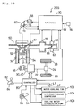
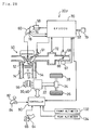
- the first power output apparatus comprises: an engine having an output shaft; engine-driving means for driving the engine; a first motor comprising a first rotor connected with the output shaft of the engine and a second rotor connected with the drive shaft, the second rotor being coaxial to and rotatable relative to the first rotor, the first and second rotors being electromagnetically connected with each other, whereby power is transmitted between the output shaft of the engine and the drive shaft via an electromagnetic coupling of the first rotor with the second rotor; a first motor-driving circuit for controlling the degree of electromagnetic coupling of the first rotor with the second rotor in the first motor and regulating the rotation of the second rotor relative to the first rotor; a second motor connected with the drive shaft; a second motor-driving circuit for driving and controlling the second motor; storage battery means connected with the first motor
- 'vehicle' here and hereinafter represents general automobiles running on the road surface without a track, train cars running on the railway, special vehicles such as cranes and fork lift trucks, and industrial machines.
- the control is carried out to allow the storage battery means to be charged at least with the predetermined electric power.
- This structure effectively prevents the storage battery means from being damaged by excessive charging, and avoids an undesirable state that can not output the power due to a full charge of the storage battery means.
- the power of the engine is output to the drive shaft via the first motor
- the power of the second motor is output to the drive shaft. Namely the required power is supplied to the drive shaft by both the engine and the second motor.
- the structure of the present invention can reduce the size of the second motor. Part or all of the electric power required by the second motor is compensated by the electric power regenerated by the first motor. This structure reduces the size of the storage battery means, compared with the conventional structure wherein all the required electric power depends upon the storage battery means.
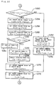
- the power prediction means further comprises means for, when the running state of the vehicle detected by the running state detection means represents a state in which the vehicle is running on a slope having a predetermined or greater rising gradient, predicting that the predetermined output state would be expected in a predetermined time period.
- This structure allows the output state of the power accompanied by the process of charging the storage battery means with excess electric power, for example, a start or a low-speed drive of the vehicle on a rising slope, to be more readily predicted.
- These conditions represent the output state of the power accompanied with the process of charging the storage battery means with excess electric power, because of the following reason.
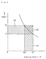
- the power required to output the drive shaft has a large torque but a small revolving speed, whereas a predetermined revolving speed is essential for outputting a large torque from the engine.
- the first power output apparatus further comprises position/direction detecting means having map information, the position/direction detecting means detecting a current position and a running direction of the vehicle in relation to the map information, wherein the power prediction means predicts the predetermined output state, based on the running state of the vehicle detected by the running state detection means and the current position and the running direction of the vehicle detected in relation to the map information by the position/direction detecting means.
- This structure enables the predetermined output state of the power, which is accompanied by the process of charging the storage battery means with excess electric power, to be more accurately predicted.
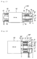
- the first motor and the second motor are constructed as a complex motor that comprises a third rotor connected with the output shaft of the engine, a fourth rotor connected with the drive shaft to be coaxial to and rotatable relative to the third rotor, and a stator for rotating the fourth rotor, the third rotor and the fourth rotor constituting the first motor comprising the first rotor and the second rotor whereas the fourth rotor and the stator constituting the second motor.
- the integral structure of the first motor and the second motor reduces the size of the whole power output apparatus.
- the present invention is further directed to a second power output apparatus mounted on a vehicle for outputting power to a drive shaft of the vehicle.
- the second power output apparatus comprises: an engine having an output shaft; engine-driving means for driving the engine; a first motor comprising a first rotor connected with the output shaft of the engine and a second rotor connected with the drive shaft, the second rotor being coaxial to and rotatable relative to the first rotor, the first and second rotors being electromagnetically connected with each other, whereby power is transmitted between the output shaft of the engine and the drive shaft via an electromagnetic coupling of the first rotor with the second rotor; a first motor-driving circuit for controlling the degree of electromagnetic coupling of the first rotor with the second rotor in the first motor and regulating the rotation of the second rotor relative to the first rotor; a second motor connected with the output shaft of the engine; a second motor-driving circuit for driving and controlling the second motor; storage battery means connected with the first motor-
- the control is carried out to allow the storage battery means to be charged at least with the predetermined electric power.
- the first motor and the second motor are constructed as a complex motor that comprises a third rotor connected with the output shaft of the engine, a fourth rotor connected with the drive shaft to be coaxial to and rotatable relative to the third rotor, and a stator for rotating the fourth rotor, the third rotor and the fourth rotor constituting the first motor comprising the first rotor and the second rotor whereas the third rotor and the stator constituting the second motor.
- the integral structure of the first motor and the second motor reduces the size of the whole power output apparatus.
- the present invention is further directed to a third power output apparatus mounted on a vehicle for outputting power to a drive shaft of the vehicle.
- the third power output apparatus comprises: an engine having an output shaft; engine-driving means for driving the engine; a first motor comprising a first rotor connected with the output shaft of the engine and a second rotor connected with the drive shaft, the second rotor being coaxial to and rotatable relative to the first rotor, the first and second rotors being electromagnetically connected with each other, whereby power is transmitted between the output shaft of the engine and the drive shaft via an electromagnetic coupling of the first rotor with the second rotor; a first motor-driving circuit for controlling the degree of electromagnetic coupling of the first rotor with the second rotor in the first motor and regulating the rotation of the second rotor relative to the first rotor; a second motor connected with the drive shaft; a second motor-driving circuit for driving and controlling the second motor; storage battery means connected with the first motor-driving
- the control is carried out to allow the storage battery means to be charged at least with the predetermined electric power.
- This structure effectively prevents the storage battery means from being damaged by excessive charging, and avoids an undesirable state that can not output the power due to a full charge of the storage battery means.
- the prediction of the running state of the vehicle is carried out, based on the current position and the running direction of the vehicle as well as the map information. This enables the output state of the power accompanied by the process of charging the storage battery means with excess electric power to be more accurately and readily predicted.
- the power of the engine is output to the drive shaft via the first motor
- the power of the second motor is output to the drive shaft.
- the required power is supplied to the drive shaft by both the engine and the second motor.
- the structure of the present invention can reduce the size of the second motor. Part or all of the electric power required by the second motor is compensated by the electric power regenerated by the first motor. This structure reduces the size of the storage battery means, compared with the conventional structure wherein all the required electric power depends upon the storage battery means.
- the map information of the position/direction detecting means comprises specific information regarding a specific area that generates the predetermined output state and requires the vehicle to run on a slope having a predetermined or greater rising gradient
- the power prediction means further comprising means for, when the current position of the vehicle detected by the position/direction detecting means corresponds to the specific area that generates the predetermined output state and is included as the specific information in the map information, predicting that the predetermined output state would be expected in a predetermined time period.
- the map information of the position/direction detecting means stores specific information regarding a specific area that generates the predetermined output state and requires the vehicle to run on a slope having a predetermined or greater rising gradient
- the power prediction means further comprising means for, when the vehicle is expected to enter, in a predetermined time period, the specific area that generates the predetermined output state and is included as the specific information in the map information, based on the current position and the running direction of the vehicle detected by the position/direction detecting means, predicting that the predetermined output state would be expected in the predetermined time period.
- the map information of the position/direction detecting means stores data regarding slopes on a driving route of the vehicle as specific information
- the power prediction means further comprising means for, when the vehicle is running on a slope having a predetermined or greater rising gradient based on the map information and the current position and the running direction of the vehicle detected by the position/direction detecting means, predicting that the predetermined output state would be expected in a predetermined time period.
- the first motor and the second motor are constructed as a complex motor that comprises a third rotor connected with the output shaft of the engine, a fourth rotor connected with the drive shaft to be coaxial to and rotatable relative to the third rotor, and a stator for rotating the fourth rotor, the third rotor and the fourth rotor constituting the first motor comprising the first rotor and the second rotor whereas the fourth rotor and the stator constituting the second motor.
- the integral structure of the first motor and the second motor reduces the size of the whole power output apparatus.
- the present invention is further directed to a fourth power output apparatus mounted on a vehicle for outputting power to a drive shaft of the vehicle.
- the fourth power output apparatus comprises: an engine having an output shaft; engine-driving means for driving the engine; a first motor comprising a first rotor connected with the output shaft of the engine and a second rotor connected with the drive shaft, the second rotor being coaxial to and rotatable relative to the first rotor, the first and second rotors being electromagnetically connected with each other, whereby power is transmitted between the output shaft of the engine and the drive shaft via an electromagnetic coupling of the first rotor with the second rotor; a first motor-driving circuit for controlling the degree of electromagnetic coupling of the first rotor with the second rotor in the first motor and regulating the rotation of the second rotor relative to the first rotor; a second motor connected with the output shaft of the engine; a second motor-driving circuit for driving and controlling the second motor; storage battery means connected with the first motor-
- the control is carried out to allow the storage battery means to be charged at least with the predetermined electric power.
- This structure effectively prevents the storage battery means from being damaged by excessive charging, and avoids an undesirable state that can not output the power due to a full charge of the storage battery means.
- the prediction of the running state of the vehicle is carried out, based on the current position and the running direction of the vehicle as well as the map information. This enables the output state of the power accompanied by the process of charging the storage battery means with excess electric power to be more accurately and readily predicted.
- the first motor and the second motor are constructed as a complex motor that comprises a third rotor connected with the output shaft of the engine, a fourth rotor connected with the drive shaft to be coaxial to and rotatable relative to the third rotor, and a stator for rotating the fourth rotor, the third rotor and the fourth rotor constituting the first motor comprising the first rotor and the second rotor whereas the third rotor and the stator constituting the second motor.
- the integral structure of the first motor and the second motor reduces the size of the whole power output apparatus.
- the present invention is further directed to a fifth power output apparatus mounted on a vehicle for outputting power to a drive shaft of the vehicle.
- the fifth power output apparatus comprises: an engine having an output shaft; a first motor comprising a first rotor connected with the output shaft of the engine and a second rotor connected with the drive shaft, the second rotor being coaxial to and rotatable relative to the first rotor, the first and second rotors being electromagnetically connected with each other, whereby power is transmitted between the output shaft of the engine and the drive shaft via an electromagnetic coupling of the first rotor with the second rotor; a first motor-driving circuit for controlling the degree of electromagnetic coupling of the first rotor with the second rotor in the first motor and regulating the rotation of the second rotor relative to the first rotor; a second motor connected with the drive shaft; a second motor-driving circuit for driving and controlling the second motor; storage battery means connected with the first motor-driving circuit and the second motor-driving circuit,
- the fifth power output apparatus supplies surplus electric power to the power-consuming means for consumption.
- This structure effectively prevents the storage battery means from being damaged by excessive charging, and avoids an undesirable state that can not output the power due to a full charge of the storage battery means.
- the power of the engine is output to the drive shaft via the first motor
- the power of the second motor is output to the drive shaft. Namely the required power is supplied to the drive shaft by both the engine and the second motor.
- the structure of the present invention can reduce the size of the second motor. Part or all of the electric power required by the second motor is compensated by the electric power regenerated by the first motor. This structure reduces the size of the storage battery means, compared with the conventional structure wherein all the required electric power depends upon the storage battery means.
- the first motor and the second motor are constructed as a complex motor that comprises a third rotor connected with the output shaft of the engine, a fourth rotor connected with the drive shaft to be coaxial to and rotatable relative to the third rotor, and a stator for rotating the fourth rotor, the third rotor and the fourth rotor constituting the first motor comprising the first rotor and the second rotor whereas the fourth rotor and the stator constituting the second motor.
- the integral structure of the first motor and the second motor reduces the size of the whole power output apparatus.
- the present invention is further directed to a sixth power output apparatus mounted on a vehicle for outputting power to a drive shaft of the vehicle.
- the sixth power output apparatus comprises: an engine having an output shaft; a first motor comprising a first rotor connected with the output shaft of the engine and a second rotor connected with the drive shaft, the second rotor being coaxial to and rotatable relative to the first rotor, the first and second rotors being electromagnetically connected with each other, whereby power is transmitted between the output shaft of the engine and the drive shaft via an electromagnetic coupling of the first rotor with the second rotor; a first motor-driving circuit for controlling the degree of electromagnetic coupling of the first rotor with the second rotor in the first motor and regulating the rotation of the second rotor relative to the first rotor; a second motor connected with the output shaft of engine; a second motor-driving circuit for driving and controlling the second motor; storage battery means connected with the first motor-driving circuit and the second motor-driving
- the sixth power output apparatus supplies surplus electric power to the power-consuming means for consumption.
- This structure effectively prevents the storage battery means from being damaged by excessive charging, and avoids an undesirable state that can not output the power due to a full charge of the storage battery means.
- the first motor and the second motor are constructed as a complex motor that comprises a third rotor connected with the output shaft of the engine, a fourth rotor connected with the drive shaft to be coaxial to and rotatable relative to the third rotor, and a stator for rotating the fourth rotor, the third rotor and the fourth rotor constituting the first motor comprising the first rotor and the second rotor whereas the third rotor and the stator constituting the second motor.
- the integral structure of the first motor and the second motor reduces the size of the whole power output apparatus.
- the present invention is further directed to a seventh power output apparatus mounted on a vehicle for outputting power to a drive shaft of the vehicle.
- the seventh power output apparatus comprises: an engine having an output shaft; engine-driving means for driving the engine; a first motor comprising a first rotor connected with the output shaft of the engine and a second rotor connected with the drive shaft, the second rotor being coaxial to and rotatable relative to the first rotor, the first and second rotors being electromagnetically connected with each other, whereby power is transmitted between the output shaft of the engine and the drive shaft via an electromagnetic coupling of the first rotor with the second rotor; a first motor-driving circuit for controlling the degree of electromagnetic coupling of the first rotor with the second rotor in the first motor and regulating the rotation of the second rotor relative to the first rotor; a second motor connected with the drive shaft; a second motor-driving circuit for driving and controlling the second motor; storage battery means connected with the first motor-driving
- the seventh power output apparatus changes the output state of the power to a specific state which is accompanied by the process of charging the storage battery means with electric power that is not greater than the chargeable level, without varying the power output to the drive shaft.
- This structure effectively prevents the storage battery means from being damaged by excessive charging, and avoids an undesirable state that can not output the power due to a full charge of the storage battery means.
- the power of the engine is output to the drive shaft via the first motor
- the power of the second motor is output to the drive shaft. Namely the required power is supplied to the drive shaft by both the engine and the second motor.
- the structure of the present invention can reduce the size of the second motor. Part or all of the electric power required by the second motor is compensated by the electric power regenerated by the first motor. This structure reduces the size of the storage battery means, compared with the conventional structure wherein all the required electric power depends upon the storage battery means.
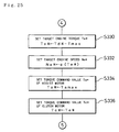
- the power control means further comprises means for controlling the engine via the engine-driving means, in order to decrease a revolving speed of the output shaft without varying a torque output from the engine to the output shaft of the engine.
- This structure decreases energy of the power output from the engine, thereby reducing the electric power used for charging the storage battery means.
- the first motor and the second motor are constructed as a complex motor that comprises a third rotor connected with the output shaft of the engine, a fourth rotor connected with the drive shaft to be coaxial to and rotatable relative to the third rotor, and a stator for rotating the fourth rotor, the third rotor and the fourth rotor constituting the first motor comprising the first rotor and the second rotor whereas the fourth rotor and the stator constituting the second motor.
- the integral structure of the first motor and the second motor reduces the size of the whole power output apparatus.
- the present invention is further directed to a eighth power output apparatus mounted on a vehicle for outputting power to a drive shaft of the vehicle.
- the seventh power output apparatus comprises: an engine having an output shaft; engine-driving means for driving the engine; a first motor comprising a first rotor connected with the output shaft of the engine and a second rotor connected with the drive shaft, the second rotor being coaxial to and rotatable relative to the first rotor, the first and second rotors being electromagnetically connected with each other, whereby power is transmitted between the output shaft of the engine and the drive shaft via an electromagnetic coupling of the first rotor with the second rotor; a first motor-driving circuit for controlling the degree of electromagnetic coupling of the first rotor with the second rotor in the first motor and regulating the rotation of the second rotor relative to the first rotor; a second motor connected with the output shaft of the engine; a second motor-driving circuit for driving and controlling the second motor; storage battery means connected with the first motor-
- the seventh power output apparatus changes the output state of the power to a specific state which is accompanied by the process of charging the storage battery means with electric power that is not greater than the chargeable level, without varying the power output to the drive shaft.
- This structure effectively prevents the storage battery means from being damaged by excessive charging, and avoids an undesirable state that can not output the power due to a full charge of the storage battery means.
- the first motor and the second motor are constructed as a complex motor that comprises a third rotor connected with the output shaft of the engine, a fourth rotor connected with the drive shaft to be coaxial to and rotatable relative to the third rotor, and a stator for rotating the fourth rotor, the third rotor and the fourth rotor constituting the first motor comprising the first rotor and the second rotor whereas the third rotor and the stator constituting the second motor.
- the integral structure of the first motor and the second motor reduces the size of the whole power output apparatus.
- a first method of controlling a power output apparatus mounted on a vehicle for outputting power to a drive shaft comprises the steps of: (a) providing an engine having an output shaft; a first motor comprising a first rotor connected with the output shaft of the engine and a second rotor connected with the drive shaft, the second rotor being coaxial to and rotatable relative to the first rotor, the first and second rotors being electromagnetically connected with each other, whereby power is transmitted between the output shaft of the engine and the drive shaft via an electromagnetic coupling of the first rotor with the second rotor; a second motor connected with the drive shaft; and storage battery means being charged with electric power and discharged to release electric power by the first motor and the second motor; (b) detecting a running state of the vehicle; (c) predicting an output state of the power to the drive shaft corresponding to a predetermined output state based on the running state of the vehicle detected in the step (b), the predetermined output state representing
- the control is carried out to allow the storage battery means to be charged at least with the predetermined electric power.
- This structure effectively prevents the storage battery means from being damaged by excessive charging, and avoids an undesirable state that can not output the power due to a full charge of the storage battery means.
- the power of the engine is output to the drive shaft via the first motor
- the power of the second motor is output to the drive shaft. Namely the required power is supplied to the drive shaft by both the engine and the second motor.
- the structure of the present invention can reduce the size of the second motor. Part or all of the electric power required by the second motor is compensated by the electric power regenerated by the first motor. This structure reduces the size of the storage battery means, compared with the conventional structure wherein all the required electric power depends upon the storage battery means.
- the present invention is further directed to a second method of controlling a power output apparatus mounted on a vehicle for outputting power to a drive shaft
- the second method comprises the steps of: (a) providing an engine having an output shaft; a first motor comprising a first rotor connected with the output shaft of the engine and a second rotor connected with the drive shaft, the second rotor being coaxial to and rotatable relative to the first rotor, the first and second rotors being electromagnetically connected with each other, whereby power is transmitted between the output shaft of the engine and the drive shaft via an electromagnetic coupling of the first rotor with the second rotor; a second motor connected with the drive shaft; and storage battery means being charged with electric power and discharged to release electric power by the first motor and the second motor; (b) detecting a current position and a running direction of the vehicle in relation to map information; (c) predicting an output state of the power to the drive shaft corresponding a predetermined output state based on the current position and the running direction of the vehicle detected in
- the control is carried out to allow the storage battery means to be charged at least with the predetermined electric power.
- This structure effectively prevents the storage battery means from being damaged by excessive charging, and avoids an undesirable state that can not output the power due to a full charge of the storage battery means.
- the prediction of the running state of the vehicle is carried out, based on the current position and the running direction of the vehicle as well as the map information. This enables the output state of the power accompanied by the process of charging the storage battery means with excess electric power to be more accurately and readily predicted.
- the power of the engine is output to the drive shaft via the first motor
- the power of the second motor is output to the drive shaft.
- the required power is supplied to the drive shaft by both the engine and the second motor.
- the structure of the present invention can reduce the size of the second motor. Part or all of the electric power required by the second motor is compensated by the electric power regenerated by the first motor. This structure reduces the size of the storage battery means, compared with the conventional structure wherein all the required electric power depends upon the storage battery means.
- the present invention is further directed to a third method of controlling a power output apparatus mounted on a vehicle for outputting power to a drive shaft
- the third method comprises the steps of: (a) providing an engine having an output shaft; a first motor comprising a first rotor connected with the output shaft of the engine and a second rotor connected with the drive shaft, the second rotor being coaxial to and rotatable relative to the first rotor, the first and second rotors being electromagnetically connected with each other, whereby power is transmitted between the output shaft of the engine and the drive shaft via an electromagnetic coupling of the first rotor with the second rotor; a second motor connected with the drive shaft; storage battery means being charged with electric power and discharged to release electric power by the first motor and the second motor; and power-consuming means that can consume electric power; (b) detecting an output state of the power to the drive shaft by the engine, the first motor, and the second motor; and (c) controlling the first motor, the second motor, and the power-consuming means, when the output
- the third method according to the present invention supplies surplus electric power to the power-consuming means for consumption.
- This structure effectively prevents the storage battery means from being damaged by excessive charging, and avoids an undesirable state that can not output the power due to a full charge of the storage battery means.
- the power of the engine is output to the drive shaft via the first motor
- the power of the second motor is output to the drive shaft. Namely the required power is supplied to the drive shaft by both the engine and the second motor.
- the structure of the present invention can reduce the size of the second motor. Part or all of the electric power required by the second motor is compensated by the electric power regenerated by the first motor. This structure reduces the size of the storage battery means, compared with the conventional structure wherein all the required electric power depends upon the storage battery means.
- the present invention is further directed to a fourth method of controlling a power output apparatus mounted on a vehicle for outputting power to a drive shaft
- the fourth method comprises the steps of: (a) providing an engine having an output shaft; a first motor comprising a first rotor connected with the output shaft of the engine and a second rotor connected with the drive shaft, the second rotor being coaxial to and rotatable relative to the first rotor, the first and second rotors being electromagnetically connected with each other, whereby power is transmitted between the output shaft of the engine and the drive shaft via an electromagnetic coupling of the first rotor with the second rotor; a second motor connected with the drive shaft; and storage battery means being charged with electric power and discharged to release electric power by the first motor and the second motor; (b) detecting an output state of the power to the drive shaft by the engine, the first motor, and the second motor; and (c) controlling the engine, the first motor, and the second motor, when the output state of the power detected in the step (b) is
- the fourth method according to the present invention changes the output state of the power to a specific state which is accompanied by the process of charging the storage battery means with electric power that is not greater than the chargeable level, without varying the power output to the drive shaft.
- This structure effectively prevents the storage battery means from being damaged by excessive charging, and avoids an undesirable state that can not output the power due to a full charge of the storage battery means.
- the power of the engine is output to the drive shaft via the first motor
- the power of the second motor is output to the drive shaft. Namely the required power is supplied to the drive shaft by both the engine and the second motor.
- the structure of the present invention can reduce the size of the second motor. Part or all of the electric power required by the second motor is compensated by the electric power regenerated by the first motor. This structure reduces the size of the storage battery means, compared with the conventional structure wherein all the required electric power depends upon the storage battery means.
- Fig. 1 is a schematic view illustrating structure of a power output apparatus 20 as a first embodiment according to the present invention
- Fig. 2 is a cross sectional view illustrating detailed structures of a clutch motor 30 and an assist motor 40 included in the power output apparatus 20 of Fig. 1
- Fig. 3 is a schematic view illustrating general structure of a vehicle with the power output apparatus 20 of Fig. 1 incorporated therein. The general structure of the vehicle is described first for the convenience of description.
- the vehicle is provided with an engine 50 driven by gasoline as a power source.
- the air ingested from an air supply system via a throttle valve 66 is mixed with fuel, that is, gasoline in this embodiment, injected from a fuel injection valve 51.
- the air/fuel mixture is supplied into a combustion chamber 52 to be explosively ignited and burned.
- Linear motion of a piston 54 pressed down by the explosion of the air/fuel mixture is converted to rotational motion of a crankshaft 56.
- the throttle valve 66 is driven to open and close by an actuator 68.
- An ignition plug 62 converts a high voltage applied from an igniter 58 via a distributor 60 to a spark, which explosively ignites and combusts the air/fuel mixture.
- the EFIECU 70 receives information from various sensors, which detect operating conditions of the engine 50. These sensors include a throttle position sensor 67 for detecting a valve travel or position BP of the throttle valve 66, a manifold vacuum sensor 72 for measuring a load applied to the engine 50, a water temperature sensor 74 for measuring the temperature of cooling water in the engine 50, and a speed sensor 76 and an angle sensor 78 mounted on the distributor 60 for measuring the revolving speed (the number of revolutions per a predetermined time period) and the rotational angle of the crankshaft 56.
- a starter switch 79 for detecting a starting condition ST of an ignition key (not shown) is also connected to the EFIECU 70. Other sensors and switches connecting with the EFIECU 70 are omitted from the illustration.
- the crankshaft 56 of the engine 50 is linked with a drive shaft 22 via a clutch motor 30 and an assist motor 40 (described later in detail).
- the drive shaft 22 further connects with a differential gear 24, which eventually transmits the torque output from the drive shaft 22 of the power output apparatus 20 to left and right driving wheels 26 and 28.
- the clutch motor 30 and the assist motor 40 are driven and controlled by a controller 80.
- the controller 80 includes an internal control CPU and receives inputs from a gearshift position sensor 84 attached to a gearshift 82 and an accelerator position sensor 65 attached to an accelerator pedal 64, as described later in detail.
- the controller 80 sends and receives a variety of data and information to and from the EFIECU 70 through communication. Details of the control procedure including a communication protocol will be described later.
- the power output apparatus 20 essentially includes the engine 50 for generating power, the clutch motor 30 with an outer rotor 32 and an inner rotor 34, the assist motor 40 with a rotor 42, and the controller 80 for driving and controlling the clutch motor 30 and the assist motor 40.
- the outer rotor 32 of the clutch motor 30 is mechanically connected to one end of the crankshaft 56 of the engine 50, whereas the inner rotor 34 thereof is mechanically linked with the rotor 42 of the assist motor 40.
- the clutch motor 30 is constructed as a synchronous motor having permanent magnets 35 attached to an inner surface of the outer rotor 32 and three-phase coils 36 wound on slots formed in the inner rotor 34. Power is supplied to the three-phase coils 36 via a rotary transformer 38. Laminated sheets of non-directional electromagnetic steel are used to form teeth and slots for the three-phase coils 36 in the inner rotor 34.
- a resolver 39 for measuring a rotational angle ⁇ e of the crankshaft 56 is attached to the crankshaft 56. The resolver 39 may also serve as the angle sensor 78 mounted on the distributor 60.
- the assist motor 40 is also constructed as a synchronous motor having three-phase coils 44, which are wound on a stator 43 fixed to a casing 45 to generate a revolving magnetic field.
- the stator 43 is also made of laminated sheets of non-directional electromagnetic steel.
- a plurality of permanent magnets 46 are attached to an outer surface of the rotor 42. In the assist motor 40, interaction between a magnetic field formed by the permanent magnets 46 and a revolving magnetic field formed by the three-phase coils 44 results in rotations of the rotor 42.
- the rotor 42 is mechanically linked with the drive shaft 22 working as the torque output shaft of the power output apparatus 20.
- a resolver 48 for measuring a rotational angle ⁇ d of the drive shaft 22 is attached to the drive shaft 22, which is further supported by a bearing 49 held in the casing 45.
- the inner rotor 34 of the clutch motor 30 is mechanically linked with the rotor 42 of the assist motor 40 and further with the drive shaft 22.
- the rotation and axial torque of the crankshaft 56 of the engine 50 are accordingly transmitted via the outer rotor 32 and the inner rotor 34 of the clutch motor 30 to the drive shaft 22 while the rotation and torque of the assist motor 40 are added to or subtracted from the transmitted rotation and torque.
- the clutch motor 30 includes two rotating elements or rotors, that is, the outer rotor 32 with the permanent magnets 35 mounted thereon and the inner rotor 34 with the three-phase coils 36 attached thereto.
- the detailed structure of the clutch motor 30 is described according to the cross sectional view of Fig. 2.
- the outer rotor 32 of the clutch motor 30 is attached to a circumferential end of a wheel 57 set around the crankshaft 56, by means of a pressure pin 59a and a screw 59b.
- a central portion of the wheel 57 is protruded to form a shaft-like element, to which the inner rotor 34 is rotatably attached by means of bearings 37A and 37B.
- One end of the drive shaft 22 is fixed to the inner rotor 34.
- a plurality of permanent magnets 35 are attached to the inner surface of the outer rotor 32 as mentioned previously.
- the permanent magnets 35 are magnetized in the direction towards the axial center of the clutch motor 30 and have magnetic poles of alternately inverted directions.
- the three-phase coils 36 of the inner rotor 34 facing to the permanent magnets 35 across a little gap are wound on a total of 12 slots (not shown) formed in the inner rotor 34.
- Supply of electricity to the respective coils forms magnetic fluxes running through the teeth (not shown), which separate the slots from one another.
- Supply of a three-phase alternating current to the respective coils rotates this magnetic field.
- the three-phase coils 36 are connected to receive electric power supplied from the rotary transformer 38.
- the rotary transformer 38 includes primary windings 38A fixed to the casing 45 and secondary windings 38B attached to the drive shaft 22 coupled with the inner rotor 34. Electromagnetic induction enables electric power to be transmitted from the primary windings 38A to the secondary windings 38B or vice versa.
- the rotary transformer 38 has windings for the three phases, that is, U, V, and W phases, to allow for the transmission of three-phase electric currents.
- the frequency of the three-phase alternating current supplied to the three-phase coils 36 is generally equal to a difference between the revolving speed (the number of revolutions per second) of the outer rotor 32 directly connected to the crankshaft 56 and the revolving speed of the inner rotor 34. This results in a slip between the rotations of the outer rotor 32 and the inner rotor 34. Details of the control procedures of the clutch motor 30 and the assist motor 40 will be described later, based on the flowcharts.
- the controller 80 includes a first driving circuit 91 for driving the clutch motor 30, a second driving circuit 92 for driving the assist motor 40, a control CPU 90 for controlling both the first and the second driving circuits 91 and 92, and a battery 94 including a number of secondary cells.
- the control CPU 90 is a one-chip microprocessor including a RAM 90a used as a working memory, a ROM 90b in which various control programs are stored, an input/output port (not shown), and a serial communication port (not shown) through which data are sent to and received from the EFIECU 70.
- the control CPU 90 receives a variety of data via the input port.
- the input data include a rotational angle ⁇ e of the crankshaft 56 of the engine 50 measured with the resolver 39, a rotational angle ⁇ d of the drive shaft 22 measured with the resolver 48, an accelerator pedal position AP (step-on amount of the accelerator pedal 64) output from the accelerator position sensor 65, a gearshift position SP output from the gearshift position sensor 84, clutch motor currents Iuc and Ivc from two ammeters 95 and 96 disposed in the first driving circuit 91, assist motor currents Iua and Iva from two ammeters 97 and 98 disposed in the second driving circuit 92, and a remaining charge BRM of the battery 94 measured with a remaining charge meter 99.
- the remaining charge meter 99 may determine the remaining charge BRM of the battery 94 by any known method; for example, by measuring the specific gravity of an electrolytic solution in the battery 94 or the whole weight of the battery 94, by computing the currents and time of charge and discharge, or by causing an instantaneous short-circuit between terminals of the battery 94 and measuring an internal resistance against the electric current.
- the control CPU 90 outputs a first control signal SW1 for driving six transistors Tr1 through Tr6 working as switching elements of the first driving circuit 91 and a second control signal SW2 for driving six transistors Tr11 through Tr16 working as switching elements of the second driving circuit 92.
- the six transistors Tr1 through Tr6 in the first driving circuit 91 constitute a transistor inverter and are arranged in pairs to work as a source and a drain with respect to a pair of power lines L1 and L2.
- the three-phase coils (U,V,W) 36 of the clutch motor 30 are connected via the rotary transformer 38 to the respective contacts of the paired transistors.
- the power lines L1 and L2 are respectively connected to plus and minus terminals of the battery 94.
- the first control signal SW1 output from the control CPU 90 thus successively controls the power-on time of the paired transistors Tr1 through Tr6.
- the electric current flowing through each coil 36 undergoes PWM (pulse width modulation) to give a quasi-sine wave, which enables the three-phase coils 36 to form a revolving magnetic field.
- the six transistors Tr11 through Tr16 in the second driving circuit 92 also constitute a transistor inverter and are arranged in the same manner as the transistors Tr1 through Tr6 in the first driving circuit 91.
- the three-phase coils (U,V,W) 44 of the assist motor 40 are connected to the respective contacts of the paired transistors.
- the second control signal SW2 output from the control CPU 90 thus successively controls the power-on time of the paired transistors Tr11 through Tr16.
- the electric current flowing through each coil 44 undergoes PWM to give a quasi-sine wave, which enables the three-phase coils 44 to form a revolving magnetic field.
- the power output apparatus 20 thus constructed works in accordance with the operation principles discussed below, especially with the principle of torque conversion.
- the engine 50 driven by the EFIECU 70 rotates at a revolving speed Ne that is equal to a predetermined value N1.
- the controller 80 does not supply any electric current to the three-phase coils 36 of the clutch motor 30 via the rotary transformer 38.
- No supply of electric current causes the outer rotor 32 of the clutch motor 30 to be electromagnetically disconnected from the inner rotor 34. This results in racing the crankshaft 56 of the engine 50.
- Under the condition that all the transistors Tr1 through Tr6 are in OFF position there is no regeneration of energy from the three-phase coils 36, and the engine 50 is kept at an idle.
- the clutch motor 30 functions as a generator, that is, carries out the regenerative operation to regenerate an electric current via the first driving circuit 91 and charges the battery 94 with the electric power thus regenerated.
- the control CPU 90 controls on and off the transistors Tr11 through Tr16 in the second driving circuit 92. The on-off control of the transistors Tr11 through Tr16 enables an electric current to flow through the three-phase coils 44 of the assist motor 40, and the assist motor 40 consequently carries out the power operation to produce a torque.
- the clutch motor 30 carries out the regenerative operation to produce energy defined by an area G1.
- the engine 50 is driven at the revolving speed Ne equal to a value N2 and with the torque Te equal to a value T2, while the drive shaft 22 is rotated at a revolving speed N1, which is greater than the revolving speed N2.
- the clutch motor 30 accordingly functions as a normal motor and consumes electric power supplied from the battery 94 to give the energy of rotational motion to the drive shaft 22.
- control CPU 90 of the controller 80 controls the second driving circuit 92 to enable the assist motor 40 to regenerate electrical energy
- a slip between the rotor 42 and the stator 43 of the assist motor 40 makes the regenerative current flow through the three-phase coils 44.
- the control CPU 90 controls both the first driving circuit 91 and the second driving circuit 92. This enables the clutch motor 30 to be driven without using electric power stored in the battery 94.
- the assist motor 40 regenerates energy corresponding to the sum of areas G2 and G3.
- the power output apparatus 20 of the embodiment can charge the battery 94 with an excess of electrical energy or discharge the battery 94 to supplement the electrical energy. This is implemented by controlling the output energy from the engine 50 (that is, the product of the torque Te and the revolving speed Ne), the electrical energy regenerated or consumed by the clutch motor 30, and the electrical energy consumed or regenerated by the assist motor 40. The output energy from the engine 50 can thus be transmitted as the power to the drive shaft 22 with a higher efficiency.
- the control CPU 90 of the controller 80 first receives data of revolving speed Nd of the drive shaft 22 at step S100.
- the revolving speed Nd of the drive shaft 22 can be computed from the rotational angle ⁇ d of the drive shaft 22 read from the resolver 48.
- the control CPU 90 reads the accelerator pedal position AP detected with the accelerator position sensor 65. The driver steps on the accelerator pedal 64 when feeling insufficiency of output torque.
- the value of the accelerator pedal position AP accordingly represents the desired output torque (that is, desired torque of the drive shaft 22) which the driver requires.
- the program then goes to step S104 at which the control CPU 90 obtains an output torque command value Td* corresponding to the input accelerator pedal position AP.
- output torque command values Td* corresponding to the respective accelerator pedal positions AP have been set in advance.
- the control CPU 90 reads out the output torque command value Td* corresponding to the input accelerator pedal position AP.
- the program then proceeds to step S108, at which it is determined whether or not the output energy Pd is equal to or greater than a minimum output energy Pemin.
- the minimum output energy Pemin is set as a minimum value that can be stably output from the engine 50 with a sufficient efficiency.
- the program carries out the processing of steps S110 through S142 shown in the flowcharts of Figs. 5 and 6.
- the program carries out the processing of steps S150 through S168 shown in the flowchart of Fig. 7.
- the output energy Pd is equal to or greater than the minimum output energy Pemin under the normal conditions. The following thus describes first the processing under the condition that Pd is not less than Pemin and then the processing under the condition that Pd is less than Pemin.
- step S110 the control CPU 90 sets a target torque Te* and a target revolving speed Ne* of the engine 50.
- the control CPU 90 sets a target torque Te* and a target revolving speed Ne* of the engine 50.
- Pd Te* ⁇ Ne*
- a favorable combination of the target torque Te* and the target revolving speed Ne* of the engine 50 is set in the following manner, in order to enable the engine 50 to be driven at a driving point of highest possible efficiency.
- Fig. 8 shows an exemplified relationship between the output energy Pd, the target engine torque Te*, and the target engine speed Ne*, which allows the engine 50 to be driven at driving points of highest possible efficiency.
- the curve A in Fig. 8 represents a boundary of an engine-operable range, in which the engine 50 can be driven, and the curve DPL represents driving points of the engine 50 with the highest possible efficiency.
- efficiency curves such as curves ⁇ 1 through ⁇ 6, can be drawn by successively joining the driving points having the identical efficiency.
- the curve DPL is obtained by joining the ridges of these efficiency curves with one another.
- the energy Pd to be output from the engine 50 is defined as the product of the engine torque Te and the engine speed Ne, and can thus be given as the curve Pd of constant output energy in Fig. 8.
- the target torque Te* and the target revolving speed Ne* of the engine 50 can be determined as a driving point at the intersection of the curve Pd of constant output energy and the curve DPL.
- such a relationship between the output energy Pd, the target engine torque Te*, and the target engine speed Ne* is stored in advance as a map in the ROM 90b.
- the target engine torque Te* and the target engine speed Ne* corresponding to the calculated output energy Pd are then read from the map.
- the output torque command value Td* obtained at step S104 is compared with the sum of the target torque Te* of the engine 50 and a maximum torque Tamax that can be output from the assist motor 40.
- the sum of the target engine torque Te* and the maximum torque Tamax represents a maximum torque that can be output to the drive shaft 22 when the engine 50 is driven with the target torque Te*. This is ascribed to the following.
- the maximum torque that can be output to the drive shaft 22 is generally expressed as the sum of the torque Tc of the clutch motor 30 and the maximum torque Tamax.
- the processing of step S112 accordingly determines whether or not the output torque Td* which the driver desires to be transmitted to the drive shaft 22 is within a possible output range from the engine 50 that is driven at a specific driving point set corresponding to the output torque Td* by the relationship of Fig. 8.
- step S114 the program proceeds to step S114, at which the difference obtained by subtracting the target engine torque Te* from the output torque command value Td* is set as a torque command value Ta* of the assist motor 40, and then to step S116, at which the target torque Te* of the engine 50 is set as a torque command value Tc* of the clutch motor 30.
- the torque command value Tc* of the clutch motor 30 is set equal to the target torque Te* of the engine 50, because the torque Tc of the clutch motor 30 is identical with the loading torque Te of the engine 50 as mentioned previously.
- the program After setting the target torque Te* and the target revolving speed Ne* of the engine 50 and the torque command values Tc* and Ta* of the clutch motor 30 and the assist motor 40, the program proceeds to steps S118, S120, and S122 to control the clutch motor 30, the assist motor 40, and the engine 50.
- the control operations of the clutch motor 30, the assist motor 40, and the engine 50 are shown as separate steps. In the actual procedure, however, these control operations are comprehensively carried out in parallel.
- the control CPU 90 simultaneously controls the clutch motor 30 and the assist motor 40 by utilizing an interrupting process, while transmitting an instruction to the EFIECU 70 through communication in order to allow the EFIECU 70 to control the engine 50 concurrently.
- Fig. 9 is a flowchart showing details of the control process of the clutch motor 30 executed at step S118 in the flowchart of Fig. 5.
- the control CPU 90 of the controller 80 first reads the rotational angle ⁇ d of the drive shaft 22 from the resolver 48 at step S170 and the rotational angle ⁇ e of the crankshaft 56 of the engine 50 from the resolver 39 at step S172.
- step S176 the control CPU 90 reads the clutch motor currents Iuc and Ivc, which respectively flow through the U phase and V phase of the three-phase coils 36 in the clutch motor 30 and are measured with the ammeters 95 and 96. Although the currents naturally flow through all the three phases U, V, and W, measurement is required only for the currents passing through the two phases since the sum of the currents is equal to zero.
- step S178 the control CPU 90 executes transformation of coordinates (three-phase to two-phase transformation) using the values of currents flowing through the three phases obtained at step S176.
- the transformation of coordinates is carried out because the currents flowing through the d and q axes are essential for the torque control in the permanent magnet-type synchronous motor.
- the torque control may be executed directly with the currents flowing through the three phases.
- the control CPU 90 computes deviations of currents Idc and Iqc actually flowing through the d and q axes from current command values Idc* and Iqc* of the respective axes, which are calculated from the torque command value Tc* of the clutch motor 30, and subsequently determines voltage command values Vdc and Vqc with respect to the d and q axes at step S180.
- Each voltage command value Vdc(Vqc) includes a part in proportion to the deviation ⁇ I from the current command value I* (the first term in the right side of Equation (3)) and a summation of historical data of the deviations ⁇ I for 'i' times (the second term in the right side).
- the control CPU 90 then re-transforms the coordinates of the voltage command values thus obtained (two-phase to three-phase transformation) at step S182. This corresponds to an inverse of the transformation executed at step S178.
- the actual voltage control is accomplished by on-off operation of the transistors Tr1 through Tr6 in the first driving circuit 91.
- the on- and off-time of the transistors Tr1 through Tr6 in the first driving circuit 91 is PWM (pulse width modulation) controlled in order to attain the voltage command values Vuc, Vvc, and Vwc determined by Equations (4) above.
- the torque command value Tc* is positive when a positive torque is applied to the drive shaft 22 in the direction of rotation of the crankshaft 56.
- a positive value is set to the torque command value Tc*.
- the transistors Tr1 through Tr6 of the first driving circuit 91 are controlled to enable a positive torque to be applied to the drive shaft 22 by the combination of the magnetic field generated by the permanent magnets 35 set on the outer rotor 32 with the revolving magnetic field generated by the currents flowing through the three-phase coils 36 mounted on the inner rotor 34 of the clutch motor 30.
- the identical switching control is executed for both the regenerative operation and the power operation of the clutch motor 30 as long as the sign of the torque command value Tc* is not changed.
- the clutch motor control routine of Fig. 9 is thus applicable to both the regenerative operation and the power operation. Under the condition of braking the drive shaft 22 or moving the vehicle in reverse, the torque command value Tc* has the negative sign.
- the clutch motor control routine of Fig. 9 is also applicable to the control procedure under such conditions, when the relative angle ⁇ c obtained at step S174 is varied in the reverse direction.
- Fig. 10 is a flowchart showing details of the torque control process of the assist motor 40 executed at step S120 in the flowchart of Fig. 5.
- the control CPU 90 then receives data of assist motor currents Iua and Iva at step S192, which respectively flow through the U phase and V phase of the three-phase coils 44 in the assist motor 40 and are measured with the ammeters 97 and 98.
- the control CPU 90 then executes transformation of coordinates for the currents of the three phases at step S194, computes voltage command values Vda and Vqa at step S196, and executes inverse transformation of coordinates for the voltage command values at step S198.
- the control CPU 90 determines the on- and off-time of the transistors Tr11 through Tr16 in the second driving circuit 92 for PWM (pulse width modulation) control.
- PWM pulse width modulation
- the torque command value Ta* of the assist motor 40 is determined by subtracting the target torque Te* of the engine 50 from the output torque command value Td* at step S114 in the flowchart of Fig. 5. It is here assumed that the drive shaft 22 is rotated in the direction of rotation of the crankshaft 56 and that the torque command value Ta* of the assist motor 40 is positive when a positive torque is applied to the drive shaft 22 in the direction of rotation of the crankshaft 56. In case that the output torque command value Td* is greater than the target engine torque Te*, a positive value is set to the torque command value Ta*, so that the assist motor 40 carries out the power operation to accelerate the rotation of the drive shaft 22.
- the assist motor 40 carries out the regenerative operation to depress the rotation of the drive shaft 22.
- the assist motor control routine of Fig. 10 is thus applicable to both the power operation and the regenerative operation of the assist motor 40. This is also true when the drive shaft 22 is rotated in reverse of the rotation of the crankshaft 56.
- the control of the engine 50 (step S122 in the flowchart of Fig. 5) is executed in the following manner.
- the control CPU 90 regulates the torque Te and the revolving speed Ne of the engine 50.
- the control CPU 90 transmits an instruction to the EFIECU 70 through communication, and the EFIECU 70 increases or decreases the amount of fuel injection from the fuel injection valve 51 or the position of the throttle valve 66, so as to make the output torque and the revolving speed of the engine 50 gradually approach the target engine torque Te* and the target engine speed Ne*.
- the torque Te of the engine 50 depends upon the loading torque Tc of the clutch motor 30, which is set equal to the torque command value Tc* by the control of the clutch motor 30 carried out at step S118 in the flowchart of Fig. 5. This means the torque command value Tc* of the clutch motor 30 is equal to the target engine torque Te*.
- the control procedure of the engine 50 accordingly makes the revolving speed of the engine 50 approach the target engine speed Ne*.
- steps S110 through S122 in the torque control routine of Fig. 5 is carried out on the assumption of an ideal state where both the clutch motor 30 and the assist motor 40 have efficiencies of 100%.
- this processing enables the power output from the engine 50 to be converted to a required torque and transmitted to the drive shaft 22 by means of the clutch motor 30 and the assist motor 40 as described previously with the drawing of Fig. 4.
- the clutch motor 30 and the assist motor 40 have efficiencies of less than 100%.
- steps S110 through S122 carried out in the power output apparatus with the real motors thus results in decreasing the power output to the drive shaft 22 corresponding to the lowered efficiencies of the motors, or alternatively discharging the battery 94 to supplement the insufficient energy.
- the target torque Te* and the target revolving speed Ne* of the engine 50 set at step S110 in the flowchart of Fig. 5 should be calculated not from the output energy Pd but from a value obtained by dividing the output energy Pd by a transmission efficiency Kt.
- the transmission efficiency Kt represents an efficiency at which the clutch motor 30 and the assist motor 40 transmit the power output from the engine 50 to the drive shaft 22.
- Equation (5) the following relationship defined by Equation (5) is used for the calculation. All the description hereinafter is also on the assumption of an ideal state where the transmission efficiency is 100%, so that the real state in the actual power output apparatus is obtained by multiplying the actual transmission efficiency Kt.
- Pd / Kt Te* ⁇ Ne*
- the program carries out the processing shown in the flowchart of Fig. 6.
- the flowchart of Fig. 6 shows the processing carried out when the output torque Td* which the driver desires to be transmitted to the drive shaft 22 is out of the possible output range from the engine 50 that is driven at a specific driving point set corresponding to the output torque Td by the relationship of Fig. 8.
- control CPU 90 of the controller 80 first subtracts the maximum torque Tamax of the assist motor 40 from the output torque command value Td* and sets the difference as a new target torque Te* of the engine 50 at step S130.
- the target revolving speed Ne* of the engine 50 corresponding to the newly set target engine torque Te* is then read from the map of Fig. 8 showing the relationship between the output energy Pd, the target engine torque Te*, and the target engine speed Ne* at step S132.
- the target engine torque Te* and the target engine speed Ne* newly set at steps S130 and S132 are both greater than those set at step S110.
- the energy Pe output from the engine 50 can thus be made greater than the output energy Pd which the driver desires.
- the charging power Pbi is then compared with a maximum chargeable power Pbimax at step S136.
- the maximum chargeable power Pbimax is determined depending upon the properties of the battery 94 and its remaining charge BRM.
- the relationship between the remaining charge BRM and the chargeable power of the battery 94 is set in advance as a map as illustrated in Fig. 11, and the maximum chargeable power Pbimax corresponding to the remaining charge BRM of the battery 94 is read from the preset map.
- Ne* Pd+Pbimax Te*
- the control CPU 90 subsequently sets the torque command value Ta* of the assist motor 40 equal to the maximum torque Tamax at step S140, and sets the torque command value Tc* of the clutch motor 30 equal to the target torque Te* of the engine 50 at step S142.
- the program returns to the processing of steps S118 through S122 in the flowchart of Fig. 5 to control the clutch motor 30, the assist motor 40, and the engine 50.
- Fig. 12 shows the state of energy at the respective driving points of the engine 50 after the processing of Fig. 6. It is here assumed that the driver steps on the accelerator pedal 64 to a significant degree during the low-speed driving of the vehicle, so as to set a large output torque command value Td*.
- the drive shaft 22 is rotated at a low revolving speed Nd under such conditions, so that the output energy Pd calculated by multiplying the revolving speed Nd by the output torque command value Td* takes a small value.
- the specific driving point of the engine 50 for generating this output energy Pd is given as a driving point DP1 in Fig.
- the driving point DP1 is defined by the target engine torque Te* and the target engine speed Ne* set at step S110 in the flowchart of Fig. 5.
- the target engine torque Te* is determined by subtracting the maximum torque Tamax from the output torque command value Td* at step S130 in the flowchart of Fig. 6.
- the specific driving point of the engine 50 corresponding to the target engine torque Te* is given as a driving point DP2 in Fig. 12 that is defined by the target engine torque Te* and the revolving speed Ne2.
- the energy Pe output from the engine 50 is expressed as the product of the target torque Te* and the revolving speed Ne2 and becomes greater than the output energy Pd required to be output to the drive shaft 22. This energy difference is obtained as the charging power Pbi and absorbed by the battery 94.
- the target revolving speed Ne* of the engine 50 is changed to make the charging power Pbi equal to the maximum chargeable power Pbimax at step S138, so as to enable the engine 50 to be driven at a driving point DP3.
- the clutch motor 30 regenerates energy or electric power expressed as the sum of areas Pbimax and Pco corresponding to the difference Nc between the revolving speed Nd of the drive shaft 22 and the revolving speed Ne of the engine 50.
- the electric power corresponding to the area Pco is given to the assist motor 40 as the electric power corresponding to an area Pai, whereas the electric power corresponding to the area Pbimax is used as the charging power Pbi for charging the battery 94.
- the engine 50 is driven at a revolving speed Ne3.
- the program carries out the processing shown in the flowchart of Fig. 7. This state is observed when the vehicle starts on an upward slope or is running on a steep upward slope.
- the control CPU 90 of the controller 80 first compares the output torque command value Td* obtained at step S104 in the flowchart of Fig. 5 with the sum of a minimum torque Temin of the engine 50 and the maximum torque Tamax of the assist motor 40 at step S150.
- the minimum torque Temin of the engine 50 represents a torque at a specific driving point that gives a minimum output energy from the engine 50 as shown in Fig. 8.
- the program carries out the processing of steps S156 through S168, which are identical with that of steps S130 through S142 in the flowchart of Fig. 6. After setting the target values and torque command values, the program returns to the processing of steps S118 through S122 in the flowchart of Fig. 5 to control the clutch motor 30, the assist motor 40, and the engine 50.
- step S152 the minimum torque Temin and a minimum revolving speed Nemin at a specific driving point that gives a minimum output torque from the engine 50 are set as the target torque Te* and the target revolving speed Ne* of the engine 50.
- the control CPU 90 subsequently sets the torque command value Ta* of the assist motor 40 equal to the difference between the output torque command value Td* and the target engine torque Te* at step S154, and sets the torque command value Tc* of the clutch motor 30 equal to the target engine torque Te* at step S168.
- the program returns to the processing of steps S118 through S122 in the flowchart of Fig. 5 to control the clutch motor 30, the assist motor 40, and the engine 50.
- the power output apparatus 20 of the first embodiment enables the power output from the engine 50 to be converted to a required torque and output to the drive shaft 22 by means of the clutch motor 30 and the assist motor 40.
- the structure of the first embodiment allows the engine to be driven at driving points with high efficiency, thereby improving the efficiency of the whole power output apparatus 20.
- the clutch motor 30, or the assist motor 40 under the condition that the energy Pe output from the engine 50 is identical with the output energy Pd required to be output to the drive shaft 22, the energy Pe output from the engine 50 is set to be greater than the output energy Pd required to be output to the drive shaft 22.
- the required torque Td* to be output from the engine 50, the clutch motor 30, and the assist motor 40.
- the excess energy generated at this moment is stored temporarily in the battery 94 and later utilized by the clutch motor 30 or the assist motor 40. This structure further improves the energy efficiency of the whole power output apparatus 20.
- the energy Pe output from the engine 50 is made greater than the output energy Pd required to be output to the drive shaft 22, in order to enable the engine 50, the clutch motor 30, and the assist motor 40 to output the required torque Td* to the drive shaft 22.
- the driving point of the engine 50 is changed by lowering the revolving speed Ne of the engine 50 while keeping the torque Te unchanged. This procedure decreases the energy Pe output from the engine 50 and effectively prevents the battery 94 from being damaged by charging with the excessively large electric power.
- the driving point of the engine 50 is determined according to the efficiency of the engine 50. In accordance with another possible application, however, the driving point of the engine 50 may be determined according to the comprehensive efficiency that takes into account the efficiency of the engine 50, the efficiencies of the clutch motor 30 and the assist motor 40, and the charge-discharge efficiency of the battery 94.
- the charging power Pbi is compared with the maximum chargeable power Pbimax and is set to be equal to or less than the maximum chargeable power Pbimax. In accordance with another possible structure, however, the charging power Pbi is compared with a predetermined value that is equal to or less than the maximum chargeable power Pbimax and is set to be not greater than the predetermined value.
- the energy Pe output from the engine 50 is made greater than the output energy Pd required to be output to the drive shaft 22, in order to enable the engine 50, the clutch motor 30, and the assist motor 40 to output the required torque Td* to the drive shaft 22.
- the driving point of the engine 50 is changed to decrease the energy Pe output from the engine 50 by lowering the revolving speed Ne of the engine 50 while keeping the torque Te unchanged.
- the driving point of the engine 50 may, however, be changed by lowering both the revolving speed Ne and the torque Te of the engine 50 according to the requirements.
- the assist motor 40 may be attached to a shaft which is separate from the drive shaft 22 but linked with the drive shaft 22 via a gear. In this latter structure, the properties of the assist motor 40 can be varied by selecting the gear ratio.
- an assist motor 40A may be interposed between the engine 50 and a clutch motor 30A, wherein a rotor 42A of the assist motor 40A is connected to an outer rotor 32A of the clutch motor 30A, which is further linked with the drive shaft 22.
- the crankshaft 56 of the engine 50 is connected to an inner rotor 34A of the clutch motor 30A, whereas the drive shaft 22 is linked with the outer rotor 32A.
- Three-phase coils 36A are accordingly mounted on the outer rotor 32A, and permanent magnets 35A on the inner rotor 34A.
- the rotary transformer 38 may be attached to the drive shaft 22 as shown in the power output apparatus 20A of Fig. 13, or alternatively be attached to a position between the clutch motor 30A and the assist motor 40A as shown in the power output apparatus 20B of Fig. 14. The position of the rotary transformer 38 can be selected adequately according to the space of the vehicle with the power output apparatus mounted thereon.
- a clutch motor 30C of the power output apparatus 20C includes an inner rotor 34C connecting with the crankshaft 56 and an outer rotor 32C linked with the drive shaft 22.
- Three-phase coils 36C are attached to the inner rotor 34C, and permanent magnets 35C are set on the outer rotor 32C in such a manner that the outer surface and the inner surface thereof have different magnetic poles.
- An assist motor 40C includes the outer rotor 32C of the clutch motor 30C and a stator 43 with three-phase coils 44 mounted thereon.
- the outer rotor 32C of the clutch motor 30C also works as the rotor of the assist motor 40C. Since the three-phase coils 36C are mounted on the inner rotor 34C linked with the crankshaft 56, the rotary transformer 38 for supplying electric power to the three-phase coils 36C of the clutch motor 30C is attached to the crankshaft 56.
- the voltage applied to the three-phase coils 36C on the inner rotor 34C is controlled against the inner-surface magnetic pole of the permanent magnets 35C set on the outer rotor 32C.
- the voltage applied to the three-phase coils 44 on the stator 43 is controlled against the outer-surface magnetic pole of the permanent magnets 35C set on the outer rotor 32C.
- the outer rotor 32C functions concurrently as one of the rotors in the clutch motor 30C and as the rotor of the assist motor 40C, thereby effectively reducing the size and weight of the power output apparatus 20C.
- assist motor 40 is attached to the drive shaft 22 in the power output apparatus 20 of the first embodiment, the assist motor 40 may be attached to the crankshaft 56 of the engine 50 as illustrated in another power output apparatus 20D of Fig. 16 given as a further modification.
- the following describes the operation of torque conversion executed in this power output apparatus 20D.
- the torque Ta of the assist motor 40 is then set to be just compensated by the electric power regenerated by the clutch motor 30, and the regenerative power is supplied to the second driving circuit 92 via the power lines L1 and L2, so that the assist motor 40 is driven with the regenerative power.
- the engine 50 is driven at another driving point of Fig. 4, where the torque Te is equal to a value T2 and the revolving speed Ne is equal to a value N2, and that the revolving speed Nd of the drive shaft 22 is equal to the value N1.
- the torque Ta of the assist motor 40 is controlled to have the value (T2-T1), the assist motor 40 carries out the regenerative operation and regenerates energy (electric power) expressed as the area G2 in Fig. 4 from the crankshaft 56.
- the clutch motor 30 accordingly functions as a normal motor and gives energy expressed as the area G1 and corresponding to the revolving speed difference Nc to the drive shaft 22 as the energy of rotational motion.
- the torque Ta of the assist motor 40 is then set to enable the electric power consumed by the clutch motor 30 to be just compensated by the electric power regenerated by the assist motor 40, so that the clutch motor 30 is driven with the electric power regenerated by the assist motor 40.
- the torque Ta of the assist motor 40 and the torque Tc of the clutch motor 30 are controlled to hold Equations (7) and (8) given below.
- This structure having the assist motor 40 attached to the crankshaft 56 of the engine 50 is also realized in still another power output apparatus 20E illustrated in Fig. 17.
- the engine 50 is interposed between the clutch motor 30 and the assist motor 40.
- an outer rotor 32F of a clutch motor 30F also works as a rotor of an assist motor 40F.
- the voltage applied to the three-phase coils 36 on the inner rotor 34 is controlled against the inner-surface magnetic pole of permanent magnets 35F set on the outer rotor 32F.
- the voltage applied to the three-phase coils 44 on the stator 43 is controlled against the outer-surface magnetic pole of the permanent magnets 35F set on the outer rotor 32F.
- the power output apparatus 20F accordingly carries out the same operations and exerts the same effects as those in the power output apparatus 20D discussed above.
- this modified structure has a further effect of reducing the size and weight of the whole power output apparatus 20F.
- FIG. 19 schematically illustrates general structure of a vehicle with the power output apparatus 20G of the second embodiment incorporated therein.
- the power output apparatus 20G of the second embodiment has a similar structure to that of the power output apparatus 20 of the first embodiment, except that connection of the power lines L1 and L2 with a motor-cooling fan 102, an air-conditioning compressor 104, a cooling water circulation pump 108 in the engine 50, and other related constituents mounted on the vehicle is clearly shown.
- the constituents of the power output apparatus 20G of the second embodiment that are identical with those of the power output apparatus 20 of the first embodiment are expressed by like numerals and not specifically described here.
- the numerals and symbols used in the description of the first embodiment have the same meanings in the description of the second embodiment, unless otherwise specified.
- the power output apparatus 20G of the second embodiment carries out a torque control routine shown in the flowcharts of Figs. 20 through 22, in place of the torque control routine of Figs. 5 through 7 executed by the power output apparatus 20 of the first embodiment.
- the following describes the essential characteristics of the torque control executed in the power output apparatus 20G of the second embodiment, based on the torque control routine of Figs. 20 through 22.
- the program executes the processing of steps S230 through S236 in the flowchart of Fig. 21, which is identical with the processing of steps S130 through S136 in the flowchart of Fig. 6.
- step S236 When the charging power Pbi is equal to or smaller than the maximum chargeable power Pbimax at step S236, the program goes to step S238, at which a surplus power Ps is set equal to zero.
- the program goes to step S240 to set the surplus power Ps by subtracting the maximum chargeable power Pbimax from the charging power Pbi and then to step S242 to correct the charging power Pbi to the maximum chargeable power Pbimax.
- the surplus power Ps is calculated by subtracting the maximum chargeable power Pbimax from the charging power Pbi and accordingly represents a quantity of electric power exceeding the chargeable power of the battery 94.
- the program then carries out the processing of steps S244 and S246, which is identical with the processing of steps S140 and S142 in the flowchart of Fig. 6. Namely the control CPU 90 sets the torque command value Ta* of the assist motor 40 equal to the maximum torque Tamax at step S244 and sets the torque command value Tc* of the clutch motor 30 equal to the target engine torque Te* at step S246. The program then returns to steps S220 through S226 in the flowchart of Fig. 20 to control the clutch motor 30, the assist motor 40, and the engine 50 and to carry out the control for forcibly consuming the surplus power.
- the control for forcibly consuming the surplus power forcibly activates power-consuming devices, such as the motor-cooling fan 102, the air-conditioning compressor 104, and the cooling water circulation pump 108, according to the value of the surplus power Ps, thereby consuming the surplus power Ps.
- power-consuming devices such as the motor-cooling fan 102, the air-conditioning compressor 104, and the cooling water circulation pump 108.
- possible combinations of surplus power Ps, power-consuming device that consumes the surplus power Ps, and driving point of the power-consuming device are stored in advance as a map.
- An appropriate power-consuming device and its driving point corresponding to the preset surplus power Ps are read from the map, and the selected power-consuming device is forcibly activated and driven at the selected driving point. This allows consumption of the surplus power Ps.
- the power-consuming device is not limited to those mentioned above, but may be any other devices mounted on the vehicle or those having discharge resistance.
- the program carries out the processing of steps S250 through S272 in the flowchart of Fig. 22, which is similar to the processing of steps S150 through S168 in the flowchart of Fig. 7 except the processing of steps S262 through S268.
- the processing of steps S262 through S268 is identical with the processing of steps S236 through S242 in the flowchart of Fig. 21.
- the clutch motor 30, or the assist motor 40 under the condition that the energy Pe output from the engine 50 is identical with the output energy Pd required to be output to the drive shaft 22, the energy Pe output from the engine 50 is set to be greater than the output energy Pd required to be output to the drive shaft 22.
- the required torque Td* to be output from the engine 50, the clutch motor 30, and the assist motor 40.
- the excess energy generated at this moment is stored temporarily in the battery 94 and later utilized by the clutch motor 30 or the assist motor 40. This structure further improves the energy efficiency of the whole power output apparatus 20G.
- the energy Pe output from the engine 50 is made greater than the output energy Pd required to be output to the drive shaft 22, in order to enable the engine 50, the clutch motor 30, and the assist motor 40 to output the required torque Td* to the drive shaft 22.
- the surplus energy to be greater the maximum chargeable power Pbimax of the battery 94
- the surplus power Ps exceeding the maximum chargeable power Pbimax is consumed by the power-consuming devices, such as the motor-cooling fan 102, the air-conditioning compressor 104, and the cooling water circulation pump 108. This procedure effectively prevents the battery 94 from being damaged by Charging with the excessively large electric power.
- the power output apparatus 20G of the second embodiment enables the power output from the engine 50 to be converted to a required torque and output to the drive shaft 22 by means of the clutch motor 30 and the assist motor 40.
- the structure of the first embodiment allows the engine to be driven at driving points with high efficiency, thereby improving the efficiency of the whole power output apparatus 20G.
- the charging power Pbi is compared with the maximum chargeable power Pbimax, and is corrected to the maximum chargeable power Pbimax when Pbi exceeds Pbimax.
- the charging power Pbi is compared with a predetermined value that is equal to or less than the maximum chargeable power Pbimax, and is corrected to the predetermined value when Pbi exceeds the predetermined value.
- the assist motor 40 may be attached to a shaft which is separate from the drive shaft 22 but linked with the drive shaft 22 via a gear.
- the properties of the assist motor 40 can be varied by selecting the gear ratio.
- the assist motor 40A may be interposed between the engine 50 and the clutch motor 30A, wherein the rotor 42A of the assist motor 40A is connected to the outer rotor 32A of the clutch motor 30A, which is further linked with the drive shaft 22.
- the clutch motor and the assist motor may be integrally joined with each other, like the power output apparatus 20C of modified structure illustrated in Fig. 15.
- the assist motor 40 may be attached to the crankshaft 56 of the engine 50, like the power output apparatuses 20D and 20E of modified structures shown in Figs. 16 and 17.
- the torque command value Tc* of the clutch motor 30 is set equal to the output torque command value Td* instead of the target engine torque Te* at steps S216, S246, and S272.
- the clutch motor and the assist motor may be integrally joined with each other, like the power output apparatus 20F of modified structure illustrated in Fig. 18.
- the charging power Pbi exceeds the maximum chargeable power Pbimax
- the charging power Pbi is corrected to the maximum chargeable power Pbimax, while the excess energy is consumed as the surplus power Ps by the power-consuming devices.
- the driving point of the engine 50 is changed to decrease the energy Pe output from the engine 50 by lowering the revolving speed Ne of the engine 50 while keeping the torque Te unchanged, as described in the torque control of the power output apparatus 20 of the first embodiment.
- FIG. 23 schematically illustrates general structure of a vehicle with the power output apparatus 20H of the third embodiment incorporated therein.
- the power output apparatus 20H of the third embodiment has a similar structure to that of the power output apparatus 20 of the first embodiment, except a navigation system 110 that outputs information regarding the current position and the running direction of the vehicle based on signals from a GPS (global positioning system) satellite and map information.
- the constituents of the power output apparatus 20H of the third embodiment that are identical with those of the power output apparatus 20 of the first embodiment are expressed by like numerals and not specifically described here.
- the numerals and symbols used in the description of the first embodiment have the same meanings in the description of the third embodiment, unless otherwise specified.
- the navigation system 110 incorporated in the power output apparatus 20H of the third embodiment includes a map information storage device 114 for storing map information, such as roads, the names of places, main buildings, and topographical data, a navigation aerial 116 for receiving signals from the GPS satellite, a gyro sensor 118 for measuring an angle of running direction of the vehicle, a vehicle speed sensor 120 for measuring a vehicle speed, a display panel 122 for displaying the map information as well as the current position and the running direction of the vehicle, and a navigation control device 112.
- map information storage device 114 for storing map information, such as roads, the names of places, main buildings, and topographical data
- a navigation aerial 116 for receiving signals from the GPS satellite
- a gyro sensor 118 for measuring an angle of running direction of the vehicle
- a vehicle speed sensor 120 for measuring a vehicle speed
- a display panel 122 for displaying the map information as well as the current position and the running direction of the vehicle
- the navigation system 110 combines radio navigation that measures the current position of the vehicle based on the signals sent from the GPS satellite with self-contained navigation that measures the moving distance and the running direction of the vehicle with the gyro sensor 118 and the vehicle speed sensor 120.
- the navigation system 110 calculates the current position and the running direction of the vehicle, the vehicle speed, available routes to a destination, and time periods required to arrive at the destination, and outputs these data with the map information to the display panel 122.
- a variety of data including topographical data, data of roads and main buildings, and data of steep slope areas that represent predetermined ranges around points having predetermined or greater gradients (for example, gradients of not less than 10%) are stored as the map information in the map information storage device 114.
- the navigation control device 112 is constructed as an arithmetic and logical operations circuit including a CPU, a ROM, a RAM, an input circuit for receiving data sent from the vehicle speed sensor 120 and the map information storage device 114, and an output circuit for outputting the map information as well as the results of operations including the current position and the running direction of the vehicle to the display panel 122 and the controller 80.
- the power output apparatus 20H of the third embodiment thus constructed carries out a torque control routine shown in the flowcharts of Figs. 24 and 25.
- the following describes the essential characteristics of the torque control executed in the power output apparatus 20H of the third embodiment, based on the torque control routine of Figs. 24 and 25.
- the condition of lower revolving speed Nd and larger output torque command value Td* is recognized as a state that requires making the energy Pe output from the engine 50 greater than the output energy Pd needed to be output to the drive shaft 22 and thereby charges the battery 94 with the resulting excess energy.
- the threshold values Ndref and Tdref respectively represent the revolving speed Nd and the output torque command value Td* set as lower limits of this state.
- the threshold value Ndref is set to be a little higher than the minimum revolving speed Nemin of the engine 50 in the graph of Fig. 8, whereas the threshold value Tdref is set equal to the sum of the minimum torque Temin of the engine 50 and the maximum torque Tamax of the assist motor 40 shown in Fig. 8.
- the program carries out the processing of steps S330 through S336 shown in the flowchart of Fig. 25.
- the program carries out the processing of steps S310 through S320 in the flowchart of Fig. 24.
- the following describes first the processing executed when either the revolving speed Nd is not lower than the threshold value Ndref or the output torque command value Td* is not greater than the threshold value Tdref and then the processing executed when the revolving speed Nd is lower than the threshold value Ndref and the output torque command value Td* is greater than the threshold value Tdref.
- the control CPU 90 reads the data of remaining charge BRM of the battery 94 at step S310, and determines whether or not the remaining charge BRM is greater than a threshold value Bref and whether or not a large-power charging prediction flag FNB is set equal to the value '1' at step S312.
- the threshold value Bref is set as the remaining charge BRM that allows the battery 94 to be charged with predicted large power, and takes a value depending upon the type, capacity, and properties of the battery 94.
- the large-power charging prediction flag FNB shows whether or not there is a possibility of charging the battery 94 with large power, and is set in a large-power charging prediction routine (shown in the flowchart of Fig. 26) that is carried out repeatedly at predetermined time intervals.
- the control CPU 90 of the controller 80 first receives data of current position and running direction of the vehicle from the navigation control device 112 of the navigation system 110 at step S340, and then receives data of steep slope areas near the current position of the vehicle from the map information storage device 114 via the navigation control device 112 at step S342.
- step S344 It is then determined at step S344 whether or not the current position of the vehicle is within a steep slope area or whether or not the vehicle is expected to enter a steep slope area in a predetermined time period.
- the program determines that the battery 94 is expected to be charged with large electric power and goes to step S346 to set the large-power charging prediction flag FNB equal to the value '1'.
- the program determines that the battery 94 is not expected to be charged with large electric power and goes to step S348 to set the large-power charging prediction flag FNB equal to the value '0'.
- the program determines that the current state does not allow the battery 94 to be charged with the predicted large power, although the current state is within a specific range for predicting that the battery 94 would be charged with large power or otherwise is expected to enter the specific range in a predetermined time period.
- the discharging power Pbo represents electric power discharged from the battery 94, and takes a value depending upon the type, the capacity, and the properties of the battery 94.
- This process of setting the target engine torque Te* and the target engine speed Ne* makes the energy Pe output from the engine 50 smaller than the output energy Pd and allows the insufficient energy to be compensated by the electric power discharged from the battery 94, thereby enabling the remaining charge BRM of the battery 94 to be equal to or less than the threshold value Bref.
- the program determines that the current state allows the battery 94 to be charged with the predicted large power or otherwise does not predict that the battery 94 would be charged with large power.
- the program accordingly proceeds to step S314 to read an adequate combination of the target torque Te* and the target revolving speed Ne* of the engine 50 corresponding to the output energy Pd from a preset map (for example, one shown in Fig. 8).
- the control CPU 90 subsequently subtracts the target engine torque Te* from the output torque command value Td* and sets the difference as the torque command value Ta* of the assist motor 40 at step S318, and sets the torque command value Tc* of the clutch motor 30 equal to the target engine torque Te* at step S320.
- the program goes to steps S322, S324 and S326 to control the clutch motor 30, the assist motor 40, and the engine 50.
- the concrete procedures of controlling the clutch motor 30, the assist motor 40, and the engine 50 carried out at steps S322 through S326 are identical with those executed at steps S118 through S122 in the torque control routine of the first embodiment shown in the flowchart of Fig. 5.
- the program carries out the processing of steps S330 through S336 shown in the flowchart of Fig. 25.
- the control CPU 90 first subtracts the maximum torque Tamax of the assist motor 40 from the output torque command value Td* and sets the difference as the target torque Te* of the engine 50 at step S330, and reads the target revolving speed Ne* of the engine 50 corresponding to the calculated target torque Te* from a preset map (for example, one shown in Fig. 8) at step S332.
- the control CPU 90 subsequently sets the torque command value Ta* of the assist motor 40 equal to the maximum torque Tamax at step S334 and sets the torque command value Tc* of the clutch motor 30 equal to the target torque Te* of the engine 50 at step S336.
- the program returns to steps S322 through S326 in the flowchart of Fig. 24 to control the clutch motor 30, the assist motor 40, and the engine 50.
- the clutch motor 30, or the assist motor 40 under the condition that the energy Pe output from the engine 50 is identical with the output energy Pd required to be output to the drive shaft 22, the energy Pe output from the engine 50 is set to be greater than the output energy Pd required to be output to the drive shaft 22.
- the required torque Td* to be output from the engine 50, the clutch motor 30, and the assist motor 40.
- the excess energy generated at this moment is stored temporarily in the battery 94 and later utilized by the clutch motor 30 or the assist motor 40. This structure further improves the energy efficiency of the whole power output apparatus 20H.
- the structure of the third embodiment predicts that the battery 94 would be charged with large power and adjusts the remaining charge BRM of the battery 94 in order to allow the battery 94 to be charged with the predicted large power. This procedure effectively prevents the battery 94 from being damaged by charging with the excessively large electric power.
- the power output apparatus 20H of the third embodiment is provided with the navigation system 110 that has the map information and determines the current position and the running direction of the vehicle based on signals sent from the GPS satellite and the gyro sensor 118.
- the structure of the third embodiment utilizes this navigation system 110 to predict with a higher accuracy that the battery 94 would be charged with large power.
- the power output apparatus 20H of the third embodiment enables the power output from the engine 50 to be converted to a required torque and output to the drive shaft 22 by means of the clutch motor 30 and the assist motor 40.
- the structure of the first embodiment allows the engine to be driven at driving points with high efficiency, thereby improving the efficiency of the whole power output apparatus 20H.
- the power output apparatus 20H of the third embodiment has the navigation system 110 that has the map information and combines radio navigation for measuring the current position of the vehicle based on the signals sent from the GPS satellite with self-contained navigation for measuring the moving distance and the running direction of the vehicle with the gyro sensor 118 and the vehicle speed sensor 120, so as to calculate the current position and the running direction of the vehicle, the vehicle speed, available routes to a destination, and time periods required to arrive at the destination. Any navigation system that has map information and accurately measures the current position and the running direction of the vehicle and the other required data may, however, be applied to the power output apparatus 20H.
- the power output apparatus 20H of the third embodiment receives data regarding the current position and the running direction of the vehicle and steep slope areas from the navigation system 110, determines whether or not the vehicle is within a steep slope area or is expected to enter a steep slope area in a predetermined time period, and predicts that the battery 94 would be charged with large electric power, based on the result of determination. Prediction of charging the battery 94 with large electric power may be carried out by executing a large-power charging prediction routine shown in the flowchart of Fig. 27, in place of the large-power charging prediction routine shown in the flowchart of Fig. 26. When the program enters the routine of Fig.
- the control CPU 90 first receives data regarding the current position and the running direction of the vehicle and slopes of the road surface from the navigation system 110 at steps S350 and S352. When it is determined that the vehicle is running on a slope having a predetermined or greater rising gradient at step S354, the program determines that the battery 94 is expected to be charged with large electric power and proceeds to step S356 to set the large-power charging prediction flag FNB equal to the value '1'. When it is determined that the vehicle is running on the road surface having the rising gradient less than the predetermined value at step S354, on the contrary, the program determines that the battery 94 is not expected to be charged with large electric power and proceeds to step S358 to set the large-power charging prediction flag FNB equal to the value '0'.
- the power output apparatus 20H of the third embodiment utilizes the navigation system 110 to determine whether or not the battery 94 is expected to be charged with large electric power.
- the prediction of charging the battery 94 with large electric power is implemented without the navigation system 110.
- Fig. 28 schematically illustrates a power output apparatus 20J of this alternative structure
- Fig. 29 shows a vehicle 130 with the power output apparatus 20J of Fig. 28 mounted thereon.
- the power output apparatus 20J has a front altimeter 132 for measuring a height HF on the front portion of the vehicle 130 and a rear altimeter 134 for measuring a height HR on the rear portion of the vehicle 130.
- This structure determines that the battery 94 is expected to be charged with large electric power, when the vehicle 130 is running on a slope having a predetermined or greater rising gradient.
- the power output apparatus 20J carries out a large-power charging prediction routine shown in the flowchart of Fig. 30, instead of the large-power charging prediction routine of Fig. 26.
- the control CPU 90 first receives data of the front height HF and the rear height HR of the vehicle 130 measured with the front altimeter 132 and the rear altimeter 134 at step S360, and subtracts the rear height HR from the front height HF of the vehicle 130 to yield a height difference ⁇ H at step S362.
- the program determines that the vehicle 130 is running on a slope having a predetermined or greater rising gradient and thereby the battery 94 is expected to be charged with large electric power and proceeds to step S366 to set the large-power charging prediction flag FNB equal to the value '1'.
- the program determines that the vehicle 130 is running on the road surface having the rising gradient less than the predetermined value and thereby the battery 94 is not expected to be charged with large electric power and proceeds to step S368 to set the large-power charging prediction flag FNB equal to the value '0'.
- the threshold value Href is set to represent the predetermined rising gradient, for example, a rising gradient of 10%.
- the assist motor 40 is directly attached to the drive shaft 22 in the power output apparatus 20H of the third embodiment.
- the assist motor 40 may, however, be attached to a shaft which is separate from the drive shaft 22 but linked with the drive shaft 22 via a gear. In this latter structure, the properties of the assist motor 40 can be varied by selecting the gear ratio.
- the assist motor 40A may be interposed between the engine 50 and the clutch motor 30A, wherein the rotor 42A of the assist motor 40A is connected to the outer rotor 32A of the clutch motor 30A, which is further linked with the drive shaft 22.
- the clutch motor and the assist motor may be integrally joined with each other, like the power output apparatus 20C of modified structure illustrated in Fig. 15.
- the assist motor 40 may alternatively be attached to the crankshaft 56 of the engine 50, like the power output apparatuses 20D and 20E of modified structures shown in Figs. 16 and 17.
- the torque command value Tc* of the clutch motor 30 is set equal to the output torque command value Td* instead of the target engine torque Te* at steps S320 and S336.
- the clutch motor and the assist motor may be integrally joined with each other, like the power output apparatus 20F of modified structure illustrated in Fig. 18.
- the power output apparatus 20 of the first embodiment shown in Fig. 1 may be applied to the vehicle with a four-wheel drive (4WD) as shown in Fig. 31.
- the assist motor 40 which is mechanically linked with the drive shaft 22 in the structure of Fig. 1, is separated from the drive shaft 22 and independently disposed in a rear-wheel portion of the vehicle in order to drive rear driving wheels 27 and 29.
- One end of the drive shaft 22 is linked with a differential gear 24 via a gear 23, so as to drive front driving wheels 26 and 28.
- the principle of the first embodiment can also be realized by this structure.
- Other possible structures include a combination of the torque control process of the first embodiment with that of the third embodiment, a combination of the torque control process of the second embodiment with that of the third embodiment, and a combination of the torque control process of the first embodiment with that of the second embodiment and that of the third embodiment.
- the gasoline engine driven by means of gasoline is used as the engine 50 in the above embodiments.
- the principle of the invention is, however, applicable to other internal combustion engines and external combustion engines, such as Diesel engines, turbine engines, and jet engines.
- Permanent magnet (PM)-type synchronous motors are used for the clutch motor 30 and the assist motor 40 in the above embodiments.
- Any other motors which can implement both the regenerative operation and the power operation such as variable reluctance (VR)-type synchronous motors, vernier motors, d.c. motors, induction motors, superconducting motors, and stepping motors, may, however, be used according to the requirements.
- VR variable reluctance
- the rotary transformer 38 used in the embodiments as means for transmitting the electric power to the clutch motor 30 may be replaced by a slip ring-brush contact, a slip ring-mercury contact, a semiconductor coupling of magnetic energy, or the like.
- Transistor inverters are used for the first and the second driving circuits 91 and 92 of the above embodiments.
- Other available examples include IGBT (insulated gate bipolar mode transistor) inverters, thyristor inverters, voltage PWM (pulse width modulation) inverters, square-wave inverters (voltage inverters and current inverters), and resonance inverters.
- the battery 94 in the above embodiments may include Pb cells, NiMH cells, Li cells, or the like cells.
- a capacitor may be used in place of the battery 94.
- the power output apparatus is mounted on the vehicle in all the above embodiments, it may be mounted on other transportation means like trains as well as a variety of industrial machines.
Abstract
Description
- The present invention relates to a power output apparatus and a method of controlling the same. More concretely, the present invention pertains to a power output apparatus for outputting power generated by an engine to a drive shaft with a high efficiency and a method of controlling such a power output apparatus.
- In known power output apparatuses mounted on a vehicle, an output shaft of an engine is electromagnetically linked with a drive shaft, which connects with a rotor of a motor, by means of an electromagnetic coupling, so that power of the engine is transmitted to the drive shaft (as disclosed in, for example, JAPANESE PATENT LAYING-OPEN GAZETTE No. 53-133814). In this prior art power output apparatus, the motor starts driving the vehicle. When the revolving speed of the motor reaches a predetermined level, an exciting current is given to the electromagnetic coupling to crank the engine, simultaneously with a supply of fuel to the engine and ignition with a spark, so that the engine starts its operation. After the start of the engine, the power output from the engine is transmitted to the drive shaft via the electromagnetic coupling to run the vehicle. When the power transmitted to the drive shaft via the electromagnetic coupling does not satisfy the required power of the drive shaft, the motor is driven to supplement the insufficiency. While transmitting the power to the drive shaft, the electromagnetic coupling regenerates electric power corresponding to a slip of its electromagnetic linkage. The regenerated electric power is stored in a battery to be used for starting the vehicle, or is used as power of the motor to supplement the insufficient power of the drive shaft.
- This power output apparatus requires a motor having a large output torque. Only the power from the motor is used to start or launch the vehicle, and the motor with a large output torque is accordingly required for sufficient acceleration. Taking into account the starting operation on a rising slope, the motor is required to have a greater output torque. The motor having a large output torque is generally rather bulky and undesirably increases the size of the whole power output apparatus. This is especially not suitable when the power output apparatus is mounted on a limited space, such as a vehicle. The battery that supplies electric power to the motor is also required to have a large capacity and thereby has a relatively large size.
- The applicant has invented a technique (not filed) of enabling the power output from an engine which starts its operation before a start of the vehicle to be transmitted to a drive shaft via an electromagnetic coupling, as well as addition of the power from a motor to the drive shaft. This lowers the required output torque of the motor and makes the whole power output apparatus relatively compact. At the moment of starting the vehicle, the revolving speed of the drive shaft is extremely small, so that the electric power regenerated by the electromagnetic coupling becomes greater than the electric power consumed by the motor. This may result in excess charging and damage the battery.
- One object of the present invention is to provide a power output apparatus that realizes a sufficient output at a time of starting the vehicle without damaging the battery, as well as a method of controlling such a power output apparatus.
- Another object of the present invention is to provide a power output apparatus having small-sized motors and battery and a method of controlling such a power output apparatus.
- At least part of the above objects is realized by a first power output apparatus mounted on a vehicle for outputting power to a drive shaft of the vehicle of the present invention. The first power output apparatus comprises: an engine having an output shaft; engine-driving means for driving the engine; a first motor comprising a first rotor connected with the output shaft of the engine and a second rotor connected with the drive shaft, the second rotor being coaxial to and rotatable relative to the first rotor, the first and second rotors being electromagnetically connected with each other, whereby power is transmitted between the output shaft of the engine and the drive shaft via an electromagnetic coupling of the first rotor with the second rotor; a first motor-driving circuit for controlling the degree of electromagnetic coupling of the first rotor with the second rotor in the first motor and regulating the rotation of the second rotor relative to the first rotor; a second motor connected with the drive shaft; a second motor-driving circuit for driving and controlling the second motor; storage battery means connected with the first motor-driving circuit and the second motor-driving circuit, the storage battery means being charged with electric power and discharged to release electric power via the first motor-driving circuit and the second motor-driving circuit; running state detection means for detecting a running state of the vehicle; power prediction means for predicting an output state of the power to the drive shaft corresponding to a predetermined output state based on the running state of the vehicle detected by the running state detection means, the predetermined output state representing the output state accompanied by a process of charging the storage battery means with electric power that is equal to or greater than a predetermined electric power; and control means for, when the predetermined output state is predicted by the power prediction means, controlling the engine via the engine-driving means and controlling the first motor and the second motor via the first motor-driving circuit and the second motor-driving circuit, so as to allow the storage battery means to be charged at least with the predetermined electric power.
- The term 'vehicle' here and hereinafter represents general automobiles running on the road surface without a track, train cars running on the railway, special vehicles such as cranes and fork lift trucks, and industrial machines.
- In the first power output apparatus of the present invention, when the predetermined output state of the power to the drive shaft, which is accompanied by a process of charging the storage battery means with electric power that is equal to or greater than a predetermined electric power, is expected, the control is carried out to allow the storage battery means to be charged at least with the predetermined electric power. This structure effectively prevents the storage battery means from being damaged by excessive charging, and avoids an undesirable state that can not output the power due to a full charge of the storage battery means. While the power of the engine is output to the drive shaft via the first motor, the power of the second motor is output to the drive shaft. Namely the required power is supplied to the drive shaft by both the engine and the second motor. Compared with the conventional structure wherein only the second motor supplies the required power to the drive shaft, the structure of the present invention can reduce the size of the second motor. Part or all of the electric power required by the second motor is compensated by the electric power regenerated by the first motor. This structure reduces the size of the storage battery means, compared with the conventional structure wherein all the required electric power depends upon the storage battery means.
- In accordance with one aspect of the first power output apparatus of the present invention, the power prediction means further comprises means for, when the running state of the vehicle detected by the running state detection means represents a state in which the vehicle is running on a slope having a predetermined or greater rising gradient, predicting that the predetermined output state would be expected in a predetermined time period. This structure allows the output state of the power accompanied by the process of charging the storage battery means with excess electric power, for example, a start or a low-speed drive of the vehicle on a rising slope, to be more readily predicted. These conditions represent the output state of the power accompanied with the process of charging the storage battery means with excess electric power, because of the following reason. The power required to output the drive shaft has a large torque but a small revolving speed, whereas a predetermined revolving speed is essential for outputting a large torque from the engine.
- In accordance with one aspect of the first power output apparatus of the present invention, the first power output apparatus further comprises position/direction detecting means having map information, the position/direction detecting means detecting a current position and a running direction of the vehicle in relation to the map information, wherein the power prediction means predicts the predetermined output state, based on the running state of the vehicle detected by the running state detection means and the current position and the running direction of the vehicle detected in relation to the map information by the position/direction detecting means. This structure enables the predetermined output state of the power, which is accompanied by the process of charging the storage battery means with excess electric power, to be more accurately predicted.
- In accordance with one aspect of the first power output apparatus of the present invention, the first motor and the second motor are constructed as a complex motor that comprises a third rotor connected with the output shaft of the engine, a fourth rotor connected with the drive shaft to be coaxial to and rotatable relative to the third rotor, and a stator for rotating the fourth rotor, the third rotor and the fourth rotor constituting the first motor comprising the first rotor and the second rotor whereas the fourth rotor and the stator constituting the second motor. The integral structure of the first motor and the second motor reduces the size of the whole power output apparatus.
- The present invention is further directed to a second power output apparatus mounted on a vehicle for outputting power to a drive shaft of the vehicle. The second power output apparatus comprises: an engine having an output shaft; engine-driving means for driving the engine; a first motor comprising a first rotor connected with the output shaft of the engine and a second rotor connected with the drive shaft, the second rotor being coaxial to and rotatable relative to the first rotor, the first and second rotors being electromagnetically connected with each other, whereby power is transmitted between the output shaft of the engine and the drive shaft via an electromagnetic coupling of the first rotor with the second rotor; a first motor-driving circuit for controlling the degree of electromagnetic coupling of the first rotor with the second rotor in the first motor and regulating the rotation of the second rotor relative to the first rotor; a second motor connected with the output shaft of the engine; a second motor-driving circuit for driving and controlling the second motor; storage battery means connected with the first motor-driving circuit and the second motor-driving circuit, the storage battery means being charged with electric power and discharged to release electric power via the first motor-driving circuit and the second motor-driving circuit; running state detection means for detecting a running state of the vehicle; power prediction means for predicting an output state of the power to the drive shaft corresponding to a predetermined output state based on the running state of the vehicle detected by the running state detection means, the predetermined output state representing the output state accompanied by a process of charging the storage battery means with electric power that is equal to or greater than a predetermined electric power; and control means for, when the predetermined output state is predicted by the power prediction means, controlling the engine via the engine-driving means and controlling the first motor and the second motor via the first motor-driving circuit and the second motor-driving circuit, so as to allow the storage battery means to be charged at least with the predetermined electric power.
- In the second power output apparatus of the present invention, when the predetermined output state of the power to the drive shaft, which is accompanied by a process of charging the storage battery means with electric power that is equal to or greater than a predetermined electric power, is expected, the control is carried out to allow the storage battery means to be charged at least with the predetermined electric power. This structure effectively prevents the storage battery means from being damaged by excessive charging, and avoids an undesirable state that can not output the power due to a full charge of the storage battery means.
- In accordance with one aspect of the second power output apparatus of the present invention, the first motor and the second motor are constructed as a complex motor that comprises a third rotor connected with the output shaft of the engine, a fourth rotor connected with the drive shaft to be coaxial to and rotatable relative to the third rotor, and a stator for rotating the fourth rotor, the third rotor and the fourth rotor constituting the first motor comprising the first rotor and the second rotor whereas the third rotor and the stator constituting the second motor. The integral structure of the first motor and the second motor reduces the size of the whole power output apparatus.
- The present invention is further directed to a third power output apparatus mounted on a vehicle for outputting power to a drive shaft of the vehicle. The third power output apparatus comprises: an engine having an output shaft; engine-driving means for driving the engine; a first motor comprising a first rotor connected with the output shaft of the engine and a second rotor connected with the drive shaft, the second rotor being coaxial to and rotatable relative to the first rotor, the first and second rotors being electromagnetically connected with each other, whereby power is transmitted between the output shaft of the engine and the drive shaft via an electromagnetic coupling of the first rotor with the second rotor; a first motor-driving circuit for controlling the degree of electromagnetic coupling of the first rotor with the second rotor in the first motor and regulating the rotation of the second rotor relative to the first rotor; a second motor connected with the drive shaft; a second motor-driving circuit for driving and controlling the second motor; storage battery means connected with the first motor-driving circuit and the second motor-driving circuit, the storage battery means being charged with electric power and discharged to release electric power via the first motor-driving circuit and the second motor-driving circuit; position/direction detecting means having map information, the position/direction detecting means detecting a current position and a running direction of the vehicle in relation to the map information; power prediction means for predicting an output state of the power to the drive shaft corresponding to a predetermined output state based on the current position and the running direction of the vehicle detected in relation to the map information by the position/direction detecting means, the predetermined output state representing the output state accompanied by a process of charging the storage battery means with electric power that is equal to or greater than a predetermined electric power; and control means for, when the predetermined output state is predicted by the power prediction means, controlling the engine via the engine-driving means and controlling the first motor and the second motor via the first motor-driving circuit and the second motor-driving circuit, so as to allow the storage battery means to be charged at least with the predetermined electric power.
- In the third power output apparatus of the present invention, when the predetermined output state of the power to the drive shaft, which is accompanied by a process of charging the storage battery means with electric power that is equal to or greater than a predetermined electric power, is expected, the control is carried out to allow the storage battery means to be charged at least with the predetermined electric power. This structure effectively prevents the storage battery means from being damaged by excessive charging, and avoids an undesirable state that can not output the power due to a full charge of the storage battery means. The prediction of the running state of the vehicle is carried out, based on the current position and the running direction of the vehicle as well as the map information. This enables the output state of the power accompanied by the process of charging the storage battery means with excess electric power to be more accurately and readily predicted. While the power of the engine is output to the drive shaft via the first motor, the power of the second motor is output to the drive shaft. Namely the required power is supplied to the drive shaft by both the engine and the second motor. Compared with the conventional structure wherein only the second motor supplies the required power to the drive shaft, the structure of the present invention can reduce the size of the second motor. Part or all of the electric power required by the second motor is compensated by the electric power regenerated by the first motor. This structure reduces the size of the storage battery means, compared with the conventional structure wherein all the required electric power depends upon the storage battery means.
- In accordance with one aspect of the third power output apparatus of the present invention, the map information of the position/direction detecting means comprises specific information regarding a specific area that generates the predetermined output state and requires the vehicle to run on a slope having a predetermined or greater rising gradient, the power prediction means further comprising means for, when the current position of the vehicle detected by the position/direction detecting means corresponds to the specific area that generates the predetermined output state and is included as the specific information in the map information, predicting that the predetermined output state would be expected in a predetermined time period.
- In accordance with another aspect of the third power output apparatus of the present invention, the map information of the position/direction detecting means stores specific information regarding a specific area that generates the predetermined output state and requires the vehicle to run on a slope having a predetermined or greater rising gradient, the power prediction means further comprising means for, when the vehicle is expected to enter, in a predetermined time period, the specific area that generates the predetermined output state and is included as the specific information in the map information, based on the current position and the running direction of the vehicle detected by the position/direction detecting means, predicting that the predetermined output state would be expected in the predetermined time period.
- These structures enable the predetermined output state of the power, which is accompanied by the process of charging the storage battery means with excess electric power, to be more accurately predicted at an earlier stage.
- In accordance with still another aspect of the third power output apparatus of the present invention, the map information of the position/direction detecting means stores data regarding slopes on a driving route of the vehicle as specific information, the power prediction means further comprising means for, when the vehicle is running on a slope having a predetermined or greater rising gradient based on the map information and the current position and the running direction of the vehicle detected by the position/direction detecting means, predicting that the predetermined output state would be expected in a predetermined time period. This structure enables the predetermined output state of the power, which is accompanied by the process of charging the storage battery means with excess electric power, to be more accurately predicted at an earlier stage.
- In accordance with still another aspect of the third power output apparatus of the present invention, the first motor and the second motor are constructed as a complex motor that comprises a third rotor connected with the output shaft of the engine, a fourth rotor connected with the drive shaft to be coaxial to and rotatable relative to the third rotor, and a stator for rotating the fourth rotor, the third rotor and the fourth rotor constituting the first motor comprising the first rotor and the second rotor whereas the fourth rotor and the stator constituting the second motor. The integral structure of the first motor and the second motor reduces the size of the whole power output apparatus.
- The present invention is further directed to a fourth power output apparatus mounted on a vehicle for outputting power to a drive shaft of the vehicle. The fourth power output apparatus comprises: an engine having an output shaft; engine-driving means for driving the engine; a first motor comprising a first rotor connected with the output shaft of the engine and a second rotor connected with the drive shaft, the second rotor being coaxial to and rotatable relative to the first rotor, the first and second rotors being electromagnetically connected with each other, whereby power is transmitted between the output shaft of the engine and the drive shaft via an electromagnetic coupling of the first rotor with the second rotor; a first motor-driving circuit for controlling the degree of electromagnetic coupling of the first rotor with the second rotor in the first motor and regulating the rotation of the second rotor relative to the first rotor; a second motor connected with the output shaft of the engine; a second motor-driving circuit for driving and controlling the second motor; storage battery means connected with the first motor-driving circuit and the second motor-driving circuit, the storage battery means being charged with electric power and discharged to release electric power via the first motor-driving circuit and the second motor-driving circuit; position/direction detecting means having map information, the position/direction detecting means detecting a current position and a running direction of the vehicle in relation to the map information; power prediction means for predicting an output state of the power to the drive shaft corresponding to a predetermined output state based on the current position and the running direction of the vehicle detected in relation to the map information by the position/direction detecting means, the predetermined output state representing the output state accompanied by a process of charging the storage battery means with electric power that is equal to or greater than a predetermined electric power; and control means for, when the predetermined output state is predicted by the power prediction means, controlling the engine via the engine-driving means and controlling the first motor and the second motor via the first motor-driving circuit and the second motor-driving circuit, so as to allow the storage battery means to be charged at least with the predetermined electric power.
- In the fourth power output apparatus of the present invention, when the predetermined output state of the power to the drive shaft, which is accompanied by a process of charging the storage battery means with electric power that is equal to or greater than a predetermined electric power, is expected, the control is carried out to allow the storage battery means to be charged at least with the predetermined electric power. This structure effectively prevents the storage battery means from being damaged by excessive charging, and avoids an undesirable state that can not output the power due to a full charge of the storage battery means. The prediction of the running state of the vehicle is carried out, based on the current position and the running direction of the vehicle as well as the map information. This enables the output state of the power accompanied by the process of charging the storage battery means with excess electric power to be more accurately and readily predicted.
- In accordance with one aspect of the fourth power output apparatus of the present invention, the first motor and the second motor are constructed as a complex motor that comprises a third rotor connected with the output shaft of the engine, a fourth rotor connected with the drive shaft to be coaxial to and rotatable relative to the third rotor, and a stator for rotating the fourth rotor, the third rotor and the fourth rotor constituting the first motor comprising the first rotor and the second rotor whereas the third rotor and the stator constituting the second motor. The integral structure of the first motor and the second motor reduces the size of the whole power output apparatus.
- The present invention is further directed to a fifth power output apparatus mounted on a vehicle for outputting power to a drive shaft of the vehicle. The fifth power output apparatus comprises: an engine having an output shaft; a first motor comprising a first rotor connected with the output shaft of the engine and a second rotor connected with the drive shaft, the second rotor being coaxial to and rotatable relative to the first rotor, the first and second rotors being electromagnetically connected with each other, whereby power is transmitted between the output shaft of the engine and the drive shaft via an electromagnetic coupling of the first rotor with the second rotor; a first motor-driving circuit for controlling the degree of electromagnetic coupling of the first rotor with the second rotor in the first motor and regulating the rotation of the second rotor relative to the first rotor; a second motor connected with the drive shaft; a second motor-driving circuit for driving and controlling the second motor; storage battery means connected with the first motor-driving circuit and the second motor-driving circuit, the storage battery means being charged with electric power and discharged to release electric power via the first motor-driving circuit and the second motor-driving circuit; power-consuming means electrically connected with the first motor-driving circuit and the second motor-driving circuit, the power-consuming means consuming at least part of the electric power regenerated via at least one of the first motor-driving circuit and the second motor-driving circuit; output state detecting means for detecting an output state of the power to the drive shaft by the engine, the first motor, and the second motor; and electric power control means for, when the output state of the power detected by the output state detecting means is accompanied by a process of charging the storage battery means with electric power that is greater than a predetermined electric power, controlling the first motor-driving circuit, the second motor-driving circuit, and the power-consuming means, in order to supply the predetermined electric power to the storage battery means which is thereby charged with the supplied electric power, while supplying a surplus power to the power-consuming means.
- Even when the predetermined output state of the power, which is accompanied with the process of charging the storage battery means with excess electric power, occurs, the fifth power output apparatus according to the present invention supplies surplus electric power to the power-consuming means for consumption. This structure effectively prevents the storage battery means from being damaged by excessive charging, and avoids an undesirable state that can not output the power due to a full charge of the storage battery means. While the power of the engine is output to the drive shaft via the first motor, the power of the second motor is output to the drive shaft. Namely the required power is supplied to the drive shaft by both the engine and the second motor. Compared with the conventional structure wherein only the second motor supplies the required power to the drive shaft, the structure of the present invention can reduce the size of the second motor. Part or all of the electric power required by the second motor is compensated by the electric power regenerated by the first motor. This structure reduces the size of the storage battery means, compared with the conventional structure wherein all the required electric power depends upon the storage battery means.
- In accordance with one aspect of the fifth power output apparatus of the present invention, the first motor and the second motor are constructed as a complex motor that comprises a third rotor connected with the output shaft of the engine, a fourth rotor connected with the drive shaft to be coaxial to and rotatable relative to the third rotor, and a stator for rotating the fourth rotor, the third rotor and the fourth rotor constituting the first motor comprising the first rotor and the second rotor whereas the fourth rotor and the stator constituting the second motor. The integral structure of the first motor and the second motor reduces the size of the whole power output apparatus.
- The present invention is further directed to a sixth power output apparatus mounted on a vehicle for outputting power to a drive shaft of the vehicle. The sixth power output apparatus comprises: an engine having an output shaft; a first motor comprising a first rotor connected with the output shaft of the engine and a second rotor connected with the drive shaft, the second rotor being coaxial to and rotatable relative to the first rotor, the first and second rotors being electromagnetically connected with each other, whereby power is transmitted between the output shaft of the engine and the drive shaft via an electromagnetic coupling of the first rotor with the second rotor; a first motor-driving circuit for controlling the degree of electromagnetic coupling of the first rotor with the second rotor in the first motor and regulating the rotation of the second rotor relative to the first rotor; a second motor connected with the output shaft of engine; a second motor-driving circuit for driving and controlling the second motor; storage battery means connected with the first motor-driving circuit and the second motor-driving circuit, the storage battery means being charged with electric power and discharged to release electric power via the first motor-driving circuit and the second motor-driving circuit; power-consuming means electrically connected with the first motor-driving circuit and the second motor-driving circuit, the power-consuming means consuming at least part of the electric power regenerated via at least one of the first motor-driving circuit and the second motor-driving circuit; output state detecting means for detecting an output state of the power to the drive shaft by the engine, the first motor, and the second motor; and electric power control means for, when the output state of the power detected by the output state detecting means is accompanied by a process of charging the storage battery means with electric power that is greater than a predetermined electric power, controlling the first motor-driving circuit, the second motor-driving circuit, and the power-consuming means, in order to supply the predetermined electric power to the storage battery means which is thereby charged with the supplied electric power, while supplying a surplus power to the power-consuming means.
- Even when the predetermined output state of the power, which is accompanied with the process of charging the storage battery means with excess electric power, occurs, the sixth power output apparatus according to the present invention supplies surplus electric power to the power-consuming means for consumption. This structure effectively prevents the storage battery means from being damaged by excessive charging, and avoids an undesirable state that can not output the power due to a full charge of the storage battery means.
- In accordance with one aspect of the sixth power output apparatus of the present invention, the first motor and the second motor are constructed as a complex motor that comprises a third rotor connected with the output shaft of the engine, a fourth rotor connected with the drive shaft to be coaxial to and rotatable relative to the third rotor, and a stator for rotating the fourth rotor, the third rotor and the fourth rotor constituting the first motor comprising the first rotor and the second rotor whereas the third rotor and the stator constituting the second motor. The integral structure of the first motor and the second motor reduces the size of the whole power output apparatus.
- The present invention is further directed to a seventh power output apparatus mounted on a vehicle for outputting power to a drive shaft of the vehicle. The seventh power output apparatus comprises: an engine having an output shaft; engine-driving means for driving the engine; a first motor comprising a first rotor connected with the output shaft of the engine and a second rotor connected with the drive shaft, the second rotor being coaxial to and rotatable relative to the first rotor, the first and second rotors being electromagnetically connected with each other, whereby power is transmitted between the output shaft of the engine and the drive shaft via an electromagnetic coupling of the first rotor with the second rotor; a first motor-driving circuit for controlling the degree of electromagnetic coupling of the first rotor with the second rotor in the first motor and regulating the rotation of the second rotor relative to the first rotor; a second motor connected with the drive shaft; a second motor-driving circuit for driving and controlling the second motor; storage battery means connected with the first motor-driving circuit and the second motor-driving circuit, the storage battery means being charged with electric power and discharged to release electric power via the first motor-driving circuit and the second motor-driving circuit; output state detecting means for detecting an output state of the power to the drive shaft by the engine, the first motor, and the second motor; and power control means for, when the output state of the power detected by the output state detecting means is accompanied by a process of charging the storage battery means with electric power that is greater than a predetermined electric power, controlling the engine via the engine-driving means and controlling the first motor and the second motor via the first motor-driving circuit and the second motor-driving circuit, in order to change the output state of the power to a specific state accompanied by a process of charging the storage battery means with electric power not greater than the predetermined electric power, without varying the power output to the drive shaft.
- When the predetermined output state of the power, which is accompanied with the process of charging the storage battery means with excess electric power, occurs, the seventh power output apparatus according to the present invention changes the output state of the power to a specific state which is accompanied by the process of charging the storage battery means with electric power that is not greater than the chargeable level, without varying the power output to the drive shaft. This structure effectively prevents the storage battery means from being damaged by excessive charging, and avoids an undesirable state that can not output the power due to a full charge of the storage battery means. While the power of the engine is output to the drive shaft via the first motor, the power of the second motor is output to the drive shaft. Namely the required power is supplied to the drive shaft by both the engine and the second motor. Compared with the conventional structure wherein only the second motor supplies the required power to the drive shaft, the structure of the present invention can reduce the size of the second motor. Part or all of the electric power required by the second motor is compensated by the electric power regenerated by the first motor. This structure reduces the size of the storage battery means, compared with the conventional structure wherein all the required electric power depends upon the storage battery means.
- In accordance with one aspect of the seventh power output apparatus of the present invention, the power control means further comprises means for controlling the engine via the engine-driving means, in order to decrease a revolving speed of the output shaft without varying a torque output from the engine to the output shaft of the engine. This structure decreases energy of the power output from the engine, thereby reducing the electric power used for charging the storage battery means.
- In accordance with another aspect of the seventh power output apparatus of the present invention, the first motor and the second motor are constructed as a complex motor that comprises a third rotor connected with the output shaft of the engine, a fourth rotor connected with the drive shaft to be coaxial to and rotatable relative to the third rotor, and a stator for rotating the fourth rotor, the third rotor and the fourth rotor constituting the first motor comprising the first rotor and the second rotor whereas the fourth rotor and the stator constituting the second motor. The integral structure of the first motor and the second motor reduces the size of the whole power output apparatus.
- The present invention is further directed to a eighth power output apparatus mounted on a vehicle for outputting power to a drive shaft of the vehicle. The seventh power output apparatus comprises: an engine having an output shaft; engine-driving means for driving the engine; a first motor comprising a first rotor connected with the output shaft of the engine and a second rotor connected with the drive shaft, the second rotor being coaxial to and rotatable relative to the first rotor, the first and second rotors being electromagnetically connected with each other, whereby power is transmitted between the output shaft of the engine and the drive shaft via an electromagnetic coupling of the first rotor with the second rotor; a first motor-driving circuit for controlling the degree of electromagnetic coupling of the first rotor with the second rotor in the first motor and regulating the rotation of the second rotor relative to the first rotor; a second motor connected with the output shaft of the engine; a second motor-driving circuit for driving and controlling the second motor; storage battery means connected with the first motor-driving circuit and the second motor-driving circuit, the storage battery means being charged with electric power and discharged to release electric power via the first motor-driving circuit and the second motor-driving circuit; output state detecting means for detecting an output state of the power to the drive shaft by the engine, the first motor, and the second motor; and power control means for, when the output state of the power detected by the output state detecting means is accompanied by a process of charging the storage battery means with electric power that is greater than a predetermined electric power, controlling the engine via the engine-driving means and controlling the first motor and the second motor via the first motor-driving circuit and the second motor-driving circuit, in order to change the output state of the power to a specific state accompanied by a process of charging the storage battery means with electric power not greater than the predetermined electric power, without varying the power output to the drive shaft.
- When the predetermined output state of the power, which is accompanied with the process of charging the storage battery means with excess electric power, occurs, the seventh power output apparatus according to the present invention changes the output state of the power to a specific state which is accompanied by the process of charging the storage battery means with electric power that is not greater than the chargeable level, without varying the power output to the drive shaft. This structure effectively prevents the storage battery means from being damaged by excessive charging, and avoids an undesirable state that can not output the power due to a full charge of the storage battery means.
- In accordance with one aspect of the eighth power output apparatus of the present invention, the first motor and the second motor are constructed as a complex motor that comprises a third rotor connected with the output shaft of the engine, a fourth rotor connected with the drive shaft to be coaxial to and rotatable relative to the third rotor, and a stator for rotating the fourth rotor, the third rotor and the fourth rotor constituting the first motor comprising the first rotor and the second rotor whereas the third rotor and the stator constituting the second motor. The integral structure of the first motor and the second motor reduces the size of the whole power output apparatus.
- At least part of the above objects is also realized by a first method of controlling a power output apparatus mounted on a vehicle for outputting power to a drive shaft. The first method comprises the steps of: (a) providing an engine having an output shaft; a first motor comprising a first rotor connected with the output shaft of the engine and a second rotor connected with the drive shaft, the second rotor being coaxial to and rotatable relative to the first rotor, the first and second rotors being electromagnetically connected with each other, whereby power is transmitted between the output shaft of the engine and the drive shaft via an electromagnetic coupling of the first rotor with the second rotor; a second motor connected with the drive shaft; and storage battery means being charged with electric power and discharged to release electric power by the first motor and the second motor; (b) detecting a running state of the vehicle; (c) predicting an output state of the power to the drive shaft corresponding to a predetermined output state based on the running state of the vehicle detected in the step (b), the predetermined output state representing the output state accompanied by a process of charging the storage battery means with electric power that is equal to or greater than a predetermined electric power; and (d) controlling the engine, the first motor, and the second motor, so as to allow the storage battery means to be charged at least with the predetermined electric power, when the predetermined output state is expected in the step (c).
- In the first method of the present invention, when the predetermined output state of the power to the drive shaft, which is accompanied by a process of charging the storage battery means with electric power that is equal to or greater than a predetermined electric power, is expected, the control is carried out to allow the storage battery means to be charged at least with the predetermined electric power. This structure effectively prevents the storage battery means from being damaged by excessive charging, and avoids an undesirable state that can not output the power due to a full charge of the storage battery means. While the power of the engine is output to the drive shaft via the first motor, the power of the second motor is output to the drive shaft. Namely the required power is supplied to the drive shaft by both the engine and the second motor. Compared with the conventional structure wherein only the second motor supplies the required power to the drive shaft, the structure of the present invention can reduce the size of the second motor. Part or all of the electric power required by the second motor is compensated by the electric power regenerated by the first motor. This structure reduces the size of the storage battery means, compared with the conventional structure wherein all the required electric power depends upon the storage battery means.
- The present invention is further directed to a second method of controlling a power output apparatus mounted on a vehicle for outputting power to a drive shaft, the second method comprises the steps of: (a) providing an engine having an output shaft; a first motor comprising a first rotor connected with the output shaft of the engine and a second rotor connected with the drive shaft, the second rotor being coaxial to and rotatable relative to the first rotor, the first and second rotors being electromagnetically connected with each other, whereby power is transmitted between the output shaft of the engine and the drive shaft via an electromagnetic coupling of the first rotor with the second rotor; a second motor connected with the drive shaft; and storage battery means being charged with electric power and discharged to release electric power by the first motor and the second motor; (b) detecting a current position and a running direction of the vehicle in relation to map information; (c) predicting an output state of the power to the drive shaft corresponding a predetermined output state based on the current position and the running direction of the vehicle detected in relation to the map information in the step (b), the predetermined output state representing the output state accompanied by a process of charging the storage battery means with electric power that is equal to or greater than a predetermined electric power; and (d) controlling the engine, the first motor, and the second motor, so as to allow the storage battery means to be charged at least with the predetermined electric power, when the predetermined output state is expected in the step (c).
- In the second method of the present invention, when the predetermined output state of the power to the drive shaft, which is accompanied by a process of charging the storage battery means with electric power that is equal to or greater than a predetermined electric power, is expected, the control is carried out to allow the storage battery means to be charged at least with the predetermined electric power. This structure effectively prevents the storage battery means from being damaged by excessive charging, and avoids an undesirable state that can not output the power due to a full charge of the storage battery means. The prediction of the running state of the vehicle is carried out, based on the current position and the running direction of the vehicle as well as the map information. This enables the output state of the power accompanied by the process of charging the storage battery means with excess electric power to be more accurately and readily predicted. While the power of the engine is output to the drive shaft via the first motor, the power of the second motor is output to the drive shaft. Namely the required power is supplied to the drive shaft by both the engine and the second motor. Compared with the conventional structure wherein only the second motor supplies the required power to the drive shaft, the structure of the present invention can reduce the size of the second motor. Part or all of the electric power required by the second motor is compensated by the electric power regenerated by the first motor. This structure reduces the size of the storage battery means, compared with the conventional structure wherein all the required electric power depends upon the storage battery means.
- The present invention is further directed to a third method of controlling a power output apparatus mounted on a vehicle for outputting power to a drive shaft, the third method comprises the steps of: (a) providing an engine having an output shaft; a first motor comprising a first rotor connected with the output shaft of the engine and a second rotor connected with the drive shaft, the second rotor being coaxial to and rotatable relative to the first rotor, the first and second rotors being electromagnetically connected with each other, whereby power is transmitted between the output shaft of the engine and the drive shaft via an electromagnetic coupling of the first rotor with the second rotor; a second motor connected with the drive shaft; storage battery means being charged with electric power and discharged to release electric power by the first motor and the second motor; and power-consuming means that can consume electric power; (b) detecting an output state of the power to the drive shaft by the engine, the first motor, and the second motor; and (c) controlling the first motor, the second motor, and the power-consuming means, when the output state of the power detected in the step (b) is accompanied by a process of charging the storage battery means with electric power that is equal to or greater than a predetermined electric power, in order to supply the predetermined electric power to the storage battery means which is thereby charged with the supplied electric power, while supplying a surplus power to the power-consuming means.
- Even when the predetermined output state of the power, which is accompanied with the process of charging the storage battery means with excess electric power, occurs, the third method according to the present invention supplies surplus electric power to the power-consuming means for consumption. This structure effectively prevents the storage battery means from being damaged by excessive charging, and avoids an undesirable state that can not output the power due to a full charge of the storage battery means. While the power of the engine is output to the drive shaft via the first motor, the power of the second motor is output to the drive shaft. Namely the required power is supplied to the drive shaft by both the engine and the second motor. Compared with the conventional structure wherein only the second motor supplies the required power to the drive shaft, the structure of the present invention can reduce the size of the second motor. Part or all of the electric power required by the second motor is compensated by the electric power regenerated by the first motor. This structure reduces the size of the storage battery means, compared with the conventional structure wherein all the required electric power depends upon the storage battery means.
- The present invention is further directed to a fourth method of controlling a power output apparatus mounted on a vehicle for outputting power to a drive shaft, the fourth method comprises the steps of: (a) providing an engine having an output shaft; a first motor comprising a first rotor connected with the output shaft of the engine and a second rotor connected with the drive shaft, the second rotor being coaxial to and rotatable relative to the first rotor, the first and second rotors being electromagnetically connected with each other, whereby power is transmitted between the output shaft of the engine and the drive shaft via an electromagnetic coupling of the first rotor with the second rotor; a second motor connected with the drive shaft; and storage battery means being charged with electric power and discharged to release electric power by the first motor and the second motor; (b) detecting an output state of the power to the drive shaft by the engine, the first motor, and the second motor; and (c) controlling the engine, the first motor, and the second motor, when the output state of the power detected in the step (b) is accompanied by a process of charging the storage battery means with electric power that is equal to or greater than a predetermined electric power, in order to change the output state of the power to a specific state accompanied by a process of charging the storage battery means with electric power not greater than the predetermined electric power, without varying the power output to the drive shaft.
- When the predetermined output state of the power, which is accompanied with the process of charging the storage battery means with excess electric power, occurs, the fourth method according to the present invention changes the output state of the power to a specific state which is accompanied by the process of charging the storage battery means with electric power that is not greater than the chargeable level, without varying the power output to the drive shaft. This structure effectively prevents the storage battery means from being damaged by excessive charging, and avoids an undesirable state that can not output the power due to a full charge of the storage battery means. While the power of the engine is output to the drive shaft via the first motor, the power of the second motor is output to the drive shaft. Namely the required power is supplied to the drive shaft by both the engine and the second motor. Compared with the conventional structure wherein only the second motor supplies the required power to the drive shaft, the structure of the present invention can reduce the size of the second motor. Part or all of the electric power required by the second motor is compensated by the electric power regenerated by the first motor. This structure reduces the size of the storage battery means, compared with the conventional structure wherein all the required electric power depends upon the storage battery means.
- These and other objects, features, aspects, and advantages of the present invention will become more apparent from the following detailed description of the preferred embodiments with the accompanying drawings.
-
- Fig. 1 is a schematic view illustrating structure of a
power output apparatus 20 as a first embodiment according to the present invention; - Fig. 2 is a cross sectional view illustrating detailed structures of a
clutch motor 30 and anassist motor 40 included in thepower output apparatus 20 of Fig. 1; - Fig. 3 is a schematic view illustrating general structure of a vehicle with the
power output apparatus 20 of Fig. 1 incorporated therein; - Fig. 4 is a graph showing the operation principle of the
power output apparatus 20; - Figs. 5 through 7 are flowcharts showing a torque control routine executed by the
control CPU 90 of thecontroller 80; - Fig. 8 shows an exemplified relationship between the output energy Pd, the target engine torque Te*, and the target engine speed Ne*;
- Fig. 9 is a flowchart showing a fundamental procedure of controlling the
clutch motor 30 executed by thecontroller 80; - Fig. 10 is a flowchart showing a fundamental procedure of controlling the
assist motor 40 executed by thecontroller 80; - Fig. 11 is a graph showing the chargeable electric power plotted against the remaining charge BRM of the
battery 94; - Fig. 12 shows the state of energy at the respective driving points of the
engine 50; - Fig. 13 schematically shows structure of another
power output apparatus 20A as a modification of thepower output apparatus 20 of the first embodiment; - Fig. 14 schematically shows structure of still another
power output apparatus 20B as another modification of thepower output apparatus 20 of the first embodiment; - Fig. 15 schematically shows structure of another
power output apparatus 20C as still another modification of thepower output apparatus 20 of the first embodiment; - Fig. 16 schematically shows structure of another
power output apparatus 20D as another modification of thepower output apparatus 20 of the first embodiment; - Fig. 17 schematically shows structure of still another
power output apparatus 20E as another modification of thepower output apparatus 20 of the first embodiment; - Fig. 18 schematically shows structure of another
power output apparatus 20F as still another modification of thepower output apparatus 20 of the first embodiment; - Fig. 19 schematically illustrates general structure of a vehicle with a
power output apparatus 20G of a second embodiment incorporated therein. - Figs. 20 through 22 are flowcharts showing a torque control routine executed by the
control CPU 90 of thecontroller 80 in the second embodiment; - Fig. 23 schematically illustrates general structure of a vehicle with a power output apparatus 20H of a third embodiment incorporated therein.
- Figs. 24 and 25 are flowcharts showing a torque control routine executed by the
control CPU 90 of thecontroller 80 in the third embodiment; - Fig. 26 is a flowchart showing a large-power charging prediction routine executed by the
control CPU 90 of thecontroller 80 in the third embodiment; - Fig. 27 is a flowchart showing another large-power charging prediction routine;
- Fig. 28 schematically illustrates general structure of a vehicle with a
power output apparatus 20J, which is a modification of the third embodiment, incorporated therein ; - Fig. 29 shows positions of a
front altimeter 132 and arear altimeter 134 in avehicle 130 having thepower output apparatus 20J of Fig. 28 mounted thereon; - Fig. 30 is a flowchart showing a large-power charging prediction routine executed by the
power output apparatus 20J; and - Fig. 31 shows an exemplified structure when the essential structure of the
power output apparatus 20 of the first embodiment shown in Fig. 1 is applied to the vehicle with a four-wheel drive - Modes of carrying out the present invention are described hereafter as preferred embodiments. Fig. 1 is a schematic view illustrating structure of a
power output apparatus 20 as a first embodiment according to the present invention; Fig. 2 is a cross sectional view illustrating detailed structures of aclutch motor 30 and anassist motor 40 included in thepower output apparatus 20 of Fig. 1; and Fig. 3 is a schematic view illustrating general structure of a vehicle with thepower output apparatus 20 of Fig. 1 incorporated therein. The general structure of the vehicle is described first for the convenience of description. - Referring to Fig. 3, the vehicle is provided with an
engine 50 driven by gasoline as a power source. The air ingested from an air supply system via athrottle valve 66 is mixed with fuel, that is, gasoline in this embodiment, injected from afuel injection valve 51. The air/fuel mixture is supplied into acombustion chamber 52 to be explosively ignited and burned. Linear motion of apiston 54 pressed down by the explosion of the air/fuel mixture is converted to rotational motion of acrankshaft 56. Thethrottle valve 66 is driven to open and close by anactuator 68. An ignition plug 62 converts a high voltage applied from anigniter 58 via adistributor 60 to a spark, which explosively ignites and combusts the air/fuel mixture. - Operation of the
engine 50 is controlled by an electronic control unit (hereinafter referred to as EFIECU) 70. TheEFIECU 70 receives information from various sensors, which detect operating conditions of theengine 50. These sensors include athrottle position sensor 67 for detecting a valve travel or position BP of thethrottle valve 66, amanifold vacuum sensor 72 for measuring a load applied to theengine 50, awater temperature sensor 74 for measuring the temperature of cooling water in theengine 50, and aspeed sensor 76 and anangle sensor 78 mounted on thedistributor 60 for measuring the revolving speed (the number of revolutions per a predetermined time period) and the rotational angle of thecrankshaft 56. Astarter switch 79 for detecting a starting condition ST of an ignition key (not shown) is also connected to theEFIECU 70. Other sensors and switches connecting with theEFIECU 70 are omitted from the illustration. - The
crankshaft 56 of theengine 50 is linked with adrive shaft 22 via aclutch motor 30 and an assist motor 40 (described later in detail). Thedrive shaft 22 further connects with adifferential gear 24, which eventually transmits the torque output from thedrive shaft 22 of thepower output apparatus 20 to left and right drivingwheels clutch motor 30 and theassist motor 40 are driven and controlled by acontroller 80. Thecontroller 80 includes an internal control CPU and receives inputs from agearshift position sensor 84 attached to agearshift 82 and anaccelerator position sensor 65 attached to anaccelerator pedal 64, as described later in detail. Thecontroller 80 sends and receives a variety of data and information to and from theEFIECU 70 through communication. Details of the control procedure including a communication protocol will be described later. - Referring to Fig. 1, the
power output apparatus 20 essentially includes theengine 50 for generating power, theclutch motor 30 with anouter rotor 32 and aninner rotor 34, theassist motor 40 with arotor 42, and thecontroller 80 for driving and controlling theclutch motor 30 and theassist motor 40. Theouter rotor 32 of theclutch motor 30 is mechanically connected to one end of thecrankshaft 56 of theengine 50, whereas theinner rotor 34 thereof is mechanically linked with therotor 42 of theassist motor 40. - Structures of the
clutch motor 30 and theassist motor 40 are described briefly. As shown in Fig. 1, theclutch motor 30 is constructed as a synchronous motor havingpermanent magnets 35 attached to an inner surface of theouter rotor 32 and three-phase coils 36 wound on slots formed in theinner rotor 34. Power is supplied to the three-phase coils 36 via arotary transformer 38. Laminated sheets of non-directional electromagnetic steel are used to form teeth and slots for the three-phase coils 36 in theinner rotor 34. Aresolver 39 for measuring a rotational angle θe of thecrankshaft 56 is attached to thecrankshaft 56. Theresolver 39 may also serve as theangle sensor 78 mounted on thedistributor 60. - The
assist motor 40 is also constructed as a synchronous motor having three-phase coils 44, which are wound on astator 43 fixed to acasing 45 to generate a revolving magnetic field. Thestator 43 is also made of laminated sheets of non-directional electromagnetic steel. A plurality ofpermanent magnets 46 are attached to an outer surface of therotor 42. In theassist motor 40, interaction between a magnetic field formed by thepermanent magnets 46 and a revolving magnetic field formed by the three-phase coils 44 results in rotations of therotor 42. Therotor 42 is mechanically linked with thedrive shaft 22 working as the torque output shaft of thepower output apparatus 20. Aresolver 48 for measuring a rotational angle θd of thedrive shaft 22 is attached to thedrive shaft 22, which is further supported by a bearing 49 held in thecasing 45. - The
inner rotor 34 of theclutch motor 30 is mechanically linked with therotor 42 of theassist motor 40 and further with thedrive shaft 22. The rotation and axial torque of thecrankshaft 56 of theengine 50 are accordingly transmitted via theouter rotor 32 and theinner rotor 34 of theclutch motor 30 to thedrive shaft 22 while the rotation and torque of theassist motor 40 are added to or subtracted from the transmitted rotation and torque. - While the
assist motor 40 is constructed as a conventional permanent magnet-type three-phase synchronous motor, theclutch motor 30 includes two rotating elements or rotors, that is, theouter rotor 32 with thepermanent magnets 35 mounted thereon and theinner rotor 34 with the three-phase coils 36 attached thereto. The detailed structure of theclutch motor 30 is described according to the cross sectional view of Fig. 2. Theouter rotor 32 of theclutch motor 30 is attached to a circumferential end of awheel 57 set around thecrankshaft 56, by means of apressure pin 59a and ascrew 59b. A central portion of thewheel 57 is protruded to form a shaft-like element, to which theinner rotor 34 is rotatably attached by means ofbearings drive shaft 22 is fixed to theinner rotor 34. - A plurality of
permanent magnets 35, eight in this embodiment, are attached to the inner surface of theouter rotor 32 as mentioned previously. Thepermanent magnets 35 are magnetized in the direction towards the axial center of theclutch motor 30 and have magnetic poles of alternately inverted directions. The three-phase coils 36 of theinner rotor 34 facing to thepermanent magnets 35 across a little gap are wound on a total of 12 slots (not shown) formed in theinner rotor 34. Supply of electricity to the respective coils forms magnetic fluxes running through the teeth (not shown), which separate the slots from one another. Supply of a three-phase alternating current to the respective coils rotates this magnetic field. The three-phase coils 36 are connected to receive electric power supplied from therotary transformer 38. Therotary transformer 38 includesprimary windings 38A fixed to thecasing 45 andsecondary windings 38B attached to thedrive shaft 22 coupled with theinner rotor 34. Electromagnetic induction enables electric power to be transmitted from theprimary windings 38A to thesecondary windings 38B or vice versa. Therotary transformer 38 has windings for the three phases, that is, U, V, and W phases, to allow for the transmission of three-phase electric currents. - Interaction between a magnetic field formed by one adjoining pair of
permanent magnets 35 and a revolving magnetic field formed by the three-phase coils 36 of theinner rotor 34 leads to a variety of behaviors of theouter rotor 32 and theinner rotor 34. The frequency of the three-phase alternating current supplied to the three-phase coils 36 is generally equal to a difference between the revolving speed (the number of revolutions per second) of theouter rotor 32 directly connected to thecrankshaft 56 and the revolving speed of theinner rotor 34. This results in a slip between the rotations of theouter rotor 32 and theinner rotor 34. Details of the control procedures of theclutch motor 30 and theassist motor 40 will be described later, based on the flowcharts. - As mentioned above, the
clutch motor 30 and theassist motor 40 are driven and controlled by thecontroller 80. Referring back to Fig. 1, thecontroller 80 includes afirst driving circuit 91 for driving theclutch motor 30, asecond driving circuit 92 for driving theassist motor 40, acontrol CPU 90 for controlling both the first and thesecond driving circuits battery 94 including a number of secondary cells. Thecontrol CPU 90 is a one-chip microprocessor including aRAM 90a used as a working memory, aROM 90b in which various control programs are stored, an input/output port (not shown), and a serial communication port (not shown) through which data are sent to and received from theEFIECU 70. Thecontrol CPU 90 receives a variety of data via the input port. The input data include a rotational angle θe of thecrankshaft 56 of theengine 50 measured with theresolver 39, a rotational angle θd of thedrive shaft 22 measured with theresolver 48, an accelerator pedal position AP (step-on amount of the accelerator pedal 64) output from theaccelerator position sensor 65, a gearshift position SP output from thegearshift position sensor 84, clutch motor currents Iuc and Ivc from twoammeters first driving circuit 91, assist motor currents Iua and Iva from twoammeters second driving circuit 92, and a remaining charge BRM of thebattery 94 measured with a remainingcharge meter 99. The remainingcharge meter 99 may determine the remaining charge BRM of thebattery 94 by any known method; for example, by measuring the specific gravity of an electrolytic solution in thebattery 94 or the whole weight of thebattery 94, by computing the currents and time of charge and discharge, or by causing an instantaneous short-circuit between terminals of thebattery 94 and measuring an internal resistance against the electric current. - The
control CPU 90 outputs a first control signal SW1 for driving six transistors Tr1 through Tr6 working as switching elements of thefirst driving circuit 91 and a second control signal SW2 for driving six transistors Tr11 through Tr16 working as switching elements of thesecond driving circuit 92. The six transistors Tr1 through Tr6 in thefirst driving circuit 91 constitute a transistor inverter and are arranged in pairs to work as a source and a drain with respect to a pair of power lines L1 and L2. The three-phase coils (U,V,W) 36 of theclutch motor 30 are connected via therotary transformer 38 to the respective contacts of the paired transistors. The power lines L1 and L2 are respectively connected to plus and minus terminals of thebattery 94. The first control signal SW1 output from thecontrol CPU 90 thus successively controls the power-on time of the paired transistors Tr1 through Tr6. The electric current flowing through eachcoil 36 undergoes PWM (pulse width modulation) to give a quasi-sine wave, which enables the three-phase coils 36 to form a revolving magnetic field. - The six transistors Tr11 through Tr16 in the
second driving circuit 92 also constitute a transistor inverter and are arranged in the same manner as the transistors Tr1 through Tr6 in thefirst driving circuit 91. The three-phase coils (U,V,W) 44 of theassist motor 40 are connected to the respective contacts of the paired transistors. The second control signal SW2 output from thecontrol CPU 90 thus successively controls the power-on time of the paired transistors Tr11 through Tr16. The electric current flowing through eachcoil 44 undergoes PWM to give a quasi-sine wave, which enables the three-phase coils 44 to form a revolving magnetic field. - The
power output apparatus 20 thus constructed works in accordance with the operation principles discussed below, especially with the principle of torque conversion. By way of example, it is assumed that theengine 50 driven by theEFIECU 70 rotates at a revolving speed Ne that is equal to a predetermined value N1. While the transistors Tr1 through Tr6 in thefirst driving circuit 91 are in OFF position, thecontroller 80 does not supply any electric current to the three-phase coils 36 of theclutch motor 30 via therotary transformer 38. No supply of electric current causes theouter rotor 32 of theclutch motor 30 to be electromagnetically disconnected from theinner rotor 34. This results in racing thecrankshaft 56 of theengine 50. Under the condition that all the transistors Tr1 through Tr6 are in OFF position, there is no regeneration of energy from the three-phase coils 36, and theengine 50 is kept at an idle. - As the
control CPU 90 of thecontroller 80 outputs the first control signal SW1 to control on and off the transistors Tr1 through Tr6 in thefirst driving circuit 91, a constant electric current flows through the three-phase coils 36 of theclutch motor 30, based on the difference between the revolving speed Ne of thecrankshaft 56 of theengine 50 and a revolving speed Nd of the drive shaft 22 (in other words, a difference
outer rotor 32 and that of theinner rotor 34 in the clutch motor 30). A certain slip accordingly exists between theouter rotor 32 and theinner rotor 34 connected with each other in theclutch motor 30. At this moment, theinner rotor 34 rotates at the revolving speed Nd, which is lower than the revolving speed Ne of the engine 50 (revolving speed of the crankshaft 56). In this state, theclutch motor 30 functions as a generator, that is, carries out the regenerative operation to regenerate an electric current via thefirst driving circuit 91 and charges thebattery 94 with the electric power thus regenerated. In order to allow theassist motor 40 to consume energy identical with the electrical energy regenerated by theclutch motor 30, thecontrol CPU 90 controls on and off the transistors Tr11 through Tr16 in thesecond driving circuit 92. The on-off control of the transistors Tr11 through Tr16 enables an electric current to flow through the three-phase coils 44 of theassist motor 40, and theassist motor 40 consequently carries out the power operation to produce a torque. - Referring to Fig. 4, when the
crankshaft 56 is driven at a revolving speed N1 and with a torque T1, theclutch motor 30 carries out the regenerative operation to produce energy defined by an area G1. The energy of the area G1 is supplied to the assistmotor 40, so as to rotate thedrive shaft 22 at a revolving speed

clutch motor 30 or the positive revolving speed difference
drive shaft 22. - In accordance with another example, it is assumed that the
engine 50 is driven at the revolving speed Ne equal to a value N2 and with the torque Te equal to a value T2, while thedrive shaft 22 is rotated at a revolving speed N1, which is greater than the revolving speed N2. In this state, theinner rotor 34 of theclutch motor 30 rotates relative to theouter rotor 32 in the direction of rotation of thedrive shaft 22 at a revolving speed defined by the absolute value of the revolving speed difference
clutch motor 30 accordingly functions as a normal motor and consumes electric power supplied from thebattery 94 to give the energy of rotational motion to thedrive shaft 22. When thecontrol CPU 90 of thecontroller 80 controls thesecond driving circuit 92 to enable theassist motor 40 to regenerate electrical energy, a slip between therotor 42 and thestator 43 of theassist motor 40 makes the regenerative current flow through the three-phase coils 44. In order to allow theclutch motor 30 to consume the electric power regenerated by theassist motor 40, thecontrol CPU 90 controls both thefirst driving circuit 91 and thesecond driving circuit 92. This enables theclutch motor 30 to be driven without using electric power stored in thebattery 94. - Referring back to Fig. 4, when the
crankshaft 56 is driven at a revolving speed

assist motor 40 regenerates energy corresponding to the sum of areas G2 and G3. The energy of the areas G2 and G3 is supplied to theclutch motor 30, so as to rotate thedrive shaft 22 at the revolving speed

- Other than the torque conversion discussed above, the
power output apparatus 20 of the embodiment can charge thebattery 94 with an excess of electrical energy or discharge thebattery 94 to supplement the electrical energy. This is implemented by controlling the output energy from the engine 50 (that is, the product of the torque Te and the revolving speed Ne), the electrical energy regenerated or consumed by theclutch motor 30, and the electrical energy consumed or regenerated by theassist motor 40. The output energy from theengine 50 can thus be transmitted as the power to thedrive shaft 22 with a higher efficiency. - The following describes a typical procedure of such torque conversion carried out according to a torque control routine shown in the flowcharts of Figs. 5 through 7. When the program enters the torque control routine of Fig. 5, the
control CPU 90 of thecontroller 80 first receives data of revolving speed Nd of thedrive shaft 22 at step S100. The revolving speed Nd of thedrive shaft 22 can be computed from the rotational angle θd of thedrive shaft 22 read from theresolver 48. At subsequent step S102, thecontrol CPU 90 reads the accelerator pedal position AP detected with theaccelerator position sensor 65. The driver steps on theaccelerator pedal 64 when feeling insufficiency of output torque. The value of the accelerator pedal position AP accordingly represents the desired output torque (that is, desired torque of the drive shaft 22) which the driver requires. The program then goes to step S104 at which thecontrol CPU 90 obtains an output torque command value Td* corresponding to the input accelerator pedal position AP. In this embodiment, output torque command values Td* corresponding to the respective accelerator pedal positions AP have been set in advance. In response to an input of the accelerator pedal position AP, thecontrol CPU 90 reads out the output torque command value Td* corresponding to the input accelerator pedal position AP. - At step S106, an amount of energy Pd to be output to the
drive shaft 22 is calculated from the output torque command value Td* obtained at step S104 and the input revolving speed Nd of thedrive shaft 22 according to the equation of
engine 50 with a sufficient efficiency. When the output energy Pd is determined to be not less than the minimum output energy Pemin, the program carries out the processing of steps S110 through S142 shown in the flowcharts of Figs. 5 and 6. When the output energy Pd is determined to be less than the minimum output energy Pemin, on the other hand, the program carries out the processing of steps S150 through S168 shown in the flowchart of Fig. 7. The output energy Pd is equal to or greater than the minimum output energy Pemin under the normal conditions. The following thus describes first the processing under the condition that Pd is not less than Pemin and then the processing under the condition that Pd is less than Pemin. - When the output energy Pd is determined to be equal to or greater than the minimum output energy Pemin at step S108, the program goes to step S110, at which the
control CPU 90 sets a target torque Te* and a target revolving speed Ne* of theengine 50. It is here assumed that all the required energy Pd to be output to thedrive shaft 22 is supplied from theengine 50. On this assumption, since the energy supplied from theengine 50 is equal to the product of the torque Te and the revolving speed Ne of theengine 50, the relationship between the output energy Pd, the target engine torque Te*, and the target engine speed Ne* can be expressed as
engine 50 is set in the following manner, in order to enable theengine 50 to be driven at a driving point of highest possible efficiency. - Fig. 8 shows an exemplified relationship between the output energy Pd, the target engine torque Te*, and the target engine speed Ne*, which allows the
engine 50 to be driven at driving points of highest possible efficiency. The curve A in Fig. 8 represents a boundary of an engine-operable range, in which theengine 50 can be driven, and the curve DPL represents driving points of theengine 50 with the highest possible efficiency. In the engine-operable range, efficiency curves, such as curves α1 through α6, can be drawn by successively joining the driving points having the identical efficiency. The curve DPL is obtained by joining the ridges of these efficiency curves with one another. The energy Pd to be output from theengine 50 is defined as the product of the engine torque Te and the engine speed Ne, and can thus be given as the curve Pd of constant output energy in Fig. 8. With respect to a known output energy Pd, the target torque Te* and the target revolving speed Ne* of theengine 50 can be determined as a driving point at the intersection of the curve Pd of constant output energy and the curve DPL. In this embodiment, such a relationship between the output energy Pd, the target engine torque Te*, and the target engine speed Ne* is stored in advance as a map in theROM 90b. The target engine torque Te* and the target engine speed Ne* corresponding to the calculated output energy Pd are then read from the map. - At subsequent step S112, the output torque command value Td* obtained at step S104 is compared with the sum of the target torque Te* of the
engine 50 and a maximum torque Tamax that can be output from theassist motor 40. The sum of the target engine torque Te* and the maximum torque Tamax represents a maximum torque that can be output to thedrive shaft 22 when theengine 50 is driven with the target torque Te*. This is ascribed to the following. The maximum torque that can be output to thedrive shaft 22 is generally expressed as the sum of the torque Tc of theclutch motor 30 and the maximum torque Tamax. The torque Tc of theclutch motor 30 is, however, identical with the loading torque Te of theengine 50 and is set equal to the target engine torque
engine 50 with the target engine torque Te*. The processing of step S112 accordingly determines whether or not the output torque Td* which the driver desires to be transmitted to thedrive shaft 22 is within a possible output range from theengine 50 that is driven at a specific driving point set corresponding to the output torque Td* by the relationship of Fig. 8. - When the output torque command value Td* is equal to or smaller than the sum of the target engine torque Te* and the maximum torque Tamax at step S112, the program proceeds to step S114, at which the difference obtained by subtracting the target engine torque Te* from the output torque command value Td* is set as a torque command value Ta* of the
assist motor 40, and then to step S116, at which the target torque Te* of theengine 50 is set as a torque command value Tc* of theclutch motor 30. The torque command value Tc* of theclutch motor 30 is set equal to the target torque Te* of theengine 50, because the torque Tc of theclutch motor 30 is identical with the loading torque Te of theengine 50 as mentioned previously. The processing carried out when the output torque command value Td* is greater than the sum of the target engine torque Te* and the maximum torque Tamax at step S112 will be described later. - After setting the target torque Te* and the target revolving speed Ne* of the
engine 50 and the torque command values Tc* and Ta* of theclutch motor 30 and theassist motor 40, the program proceeds to steps S118, S120, and S122 to control theclutch motor 30, theassist motor 40, and theengine 50. As a matter of convenience of illustration, the control operations of theclutch motor 30, theassist motor 40, and theengine 50 are shown as separate steps. In the actual procedure, however, these control operations are comprehensively carried out in parallel. By way of example, thecontrol CPU 90 simultaneously controls theclutch motor 30 and theassist motor 40 by utilizing an interrupting process, while transmitting an instruction to theEFIECU 70 through communication in order to allow theEFIECU 70 to control theengine 50 concurrently. - Fig. 9 is a flowchart showing details of the control process of the
clutch motor 30 executed at step S118 in the flowchart of Fig. 5. When the program enters the clutch motor control routine, thecontrol CPU 90 of thecontroller 80 first reads the rotational angle θd of thedrive shaft 22 from theresolver 48 at step S170 and the rotational angle θe of thecrankshaft 56 of theengine 50 from theresolver 39 at step S172. Thecontrol CPU 90 then calculates a electrical angle θc of he clutchmotor 30 by the equation of
- The program proceeds to step S176, at which the
control CPU 90 reads the clutch motor currents Iuc and Ivc, which respectively flow through the U phase and V phase of the three-phase coils 36 in theclutch motor 30 and are measured with theammeters control CPU 90 executes transformation of coordinates (three-phase to two-phase transformation) using the values of currents flowing through the three phases obtained at step S176. The transformation of coordinates maps the values of currents flowing through the three phases to the values of currents passing through d and q axes of the permanent magnet-type synchronous motor and is executed according to Equations (1) given below:
- The transformation of coordinates is carried out because the currents flowing through the d and q axes are essential for the torque control in the permanent magnet-type synchronous motor. Alternatively, the torque control may be executed directly with the currents flowing through the three phases. After the transformation to the currents of two axes, the
control CPU 90 computes deviations of currents Idc and Iqc actually flowing through the d and q axes from current command values Idc* and Iqc* of the respective axes, which are calculated from the torque command value Tc* of theclutch motor 30, and subsequently determines voltage command values Vdc and Vqc with respect to the d and q axes at step S180. In accordance with a concrete procedure, thecontrol CPU 90 executes arithmetic operations of Equations (2) and Equations (3) given below:
control CPU 90 then re-transforms the coordinates of the voltage command values thus obtained (two-phase to three-phase transformation) at step S182. This corresponds to an inverse of the transformation executed at step S178. The inverse transformation determines voltages Vuc, Vvc, and Vwc actually applied to the three-phase coils 36 as expressed by Equations (4) given below:
- The actual voltage control is accomplished by on-off operation of the transistors Tr1 through Tr6 in the
first driving circuit 91. At step S184, the on- and off-time of the transistors Tr1 through Tr6 in thefirst driving circuit 91 is PWM (pulse width modulation) controlled in order to attain the voltage command values Vuc, Vvc, and Vwc determined by Equations (4) above. - The torque command value Tc* is positive when a positive torque is applied to the
drive shaft 22 in the direction of rotation of thecrankshaft 56. By way of example, it is assumed that a positive value is set to the torque command value Tc*. When the revolving speed Ne of theengine 50 is greater than the revolving speed Nd of thedrive shaft 22 on this assumption, that is, when the revolving speed difference
clutch motor 30 is controlled to carry out the regenerative operation and produce a regenerative current according to the revolving speed difference Nc. When the revolving speed Ne of theengine 50 is lower than the revolving speed Nd of thedrive shaft 22, that is, when the revolving speed difference
clutch motor 30 is controlled to carry out the power operation and rotate relative to thecrankshaft 56 in the direction of rotation of thedrive shaft 22 at a revolving speed defined by the absolute value of the revolving speed difference Nc. For the positive torque command value Tc*, both the regenerative operation and the power operation of theclutch motor 30 implement the identical switching control. In accordance with a concrete procedure, the transistors Tr1 through Tr6 of thefirst driving circuit 91 are controlled to enable a positive torque to be applied to thedrive shaft 22 by the combination of the magnetic field generated by thepermanent magnets 35 set on theouter rotor 32 with the revolving magnetic field generated by the currents flowing through the three-phase coils 36 mounted on theinner rotor 34 of theclutch motor 30. The identical switching control is executed for both the regenerative operation and the power operation of theclutch motor 30 as long as the sign of the torque command value Tc* is not changed. The clutch motor control routine of Fig. 9 is thus applicable to both the regenerative operation and the power operation. Under the condition of braking thedrive shaft 22 or moving the vehicle in reverse, the torque command value Tc* has the negative sign. The clutch motor control routine of Fig. 9 is also applicable to the control procedure under such conditions, when the relative angle θc obtained at step S174 is varied in the reverse direction. - Fig. 10 is a flowchart showing details of the torque control process of the
assist motor 40 executed at step S120 in the flowchart of Fig. 5. When the program enters the assist motor control routine, thecontrol CPU 90 of thecontroller 80 first reads the rotational angle θd of thedrive shaft 22 from theresolver 48 at step S190, and calculates a electrical angle θa of theassist motor 40 by the equation of
control CPU 90 then receives data of assist motor currents Iua and Iva at step S192, which respectively flow through the U phase and V phase of the three-phase coils 44 in theassist motor 40 and are measured with theammeters control CPU 90 then executes transformation of coordinates for the currents of the three phases at step S194, computes voltage command values Vda and Vqa at step S196, and executes inverse transformation of coordinates for the voltage command values at step S198. At subsequent step S199, thecontrol CPU 90 determines the on- and off-time of the transistors Tr11 through Tr16 in thesecond driving circuit 92 for PWM (pulse width modulation) control. The processing executed at steps S194 through S199 is similar to that executed at steps S178 through S184 of the clutch motor control routine shown in the flowchart of Fig. 9. - The torque command value Ta* of the
assist motor 40 is determined by subtracting the target torque Te* of theengine 50 from the output torque command value Td* at step S114 in the flowchart of Fig. 5. It is here assumed that thedrive shaft 22 is rotated in the direction of rotation of thecrankshaft 56 and that the torque command value Ta* of theassist motor 40 is positive when a positive torque is applied to thedrive shaft 22 in the direction of rotation of thecrankshaft 56. In case that the output torque command value Td* is greater than the target engine torque Te*, a positive value is set to the torque command value Ta*, so that theassist motor 40 carries out the power operation to accelerate the rotation of thedrive shaft 22. In case that the output torque command value Td* is smaller than the target engine torque Te*, on the contrary, a negative value is set to the torque command value Ta*, so that theassist motor 40 carries out the regenerative operation to depress the rotation of thedrive shaft 22. Like the control of theclutch motor 30, the assist motor control routine of Fig. 10 is thus applicable to both the power operation and the regenerative operation of theassist motor 40. This is also true when thedrive shaft 22 is rotated in reverse of the rotation of thecrankshaft 56. - The control of the engine 50 (step S122 in the flowchart of Fig. 5) is executed in the following manner. In order to enable the
engine 50 to be stationarily driven at a driving point defined by the target engine torque Te* and the target engine speed Ne* set at step S110 in Fig. 5, thecontrol CPU 90 regulates the torque Te and the revolving speed Ne of theengine 50. In accordance with a concrete procedure, thecontrol CPU 90 transmits an instruction to theEFIECU 70 through communication, and theEFIECU 70 increases or decreases the amount of fuel injection from thefuel injection valve 51 or the position of thethrottle valve 66, so as to make the output torque and the revolving speed of theengine 50 gradually approach the target engine torque Te* and the target engine speed Ne*. The torque Te of theengine 50 depends upon the loading torque Tc of theclutch motor 30, which is set equal to the torque command value Tc* by the control of theclutch motor 30 carried out at step S118 in the flowchart of Fig. 5. This means the torque command value Tc* of theclutch motor 30 is equal to the target engine torque Te*. The control procedure of theengine 50 accordingly makes the revolving speed of theengine 50 approach the target engine speed Ne*. - For the clarity of explanation, the processing of steps S110 through S122 in the torque control routine of Fig. 5 is carried out on the assumption of an ideal state where both the
clutch motor 30 and theassist motor 40 have efficiencies of 100%. In case that the efficiencies of theclutch motor 30 and theassist motor 40 are 100%, this processing enables the power output from theengine 50 to be converted to a required torque and transmitted to thedrive shaft 22 by means of theclutch motor 30 and theassist motor 40 as described previously with the drawing of Fig. 4. In the actual state, however, theclutch motor 30 and theassist motor 40 have efficiencies of less than 100%. The processing of steps S110 through S122 carried out in the power output apparatus with the real motors thus results in decreasing the power output to thedrive shaft 22 corresponding to the lowered efficiencies of the motors, or alternatively discharging thebattery 94 to supplement the insufficient energy. In order to avoid decreasing the power output to thedrive shaft 22 or discharging thebattery 94, the target torque Te* and the target revolving speed Ne* of theengine 50 set at step S110 in the flowchart of Fig. 5 should be calculated not from the output energy Pd but from a value obtained by dividing the output energy Pd by a transmission efficiency Kt. The transmission efficiency Kt represents an efficiency at which theclutch motor 30 and theassist motor 40 transmit the power output from theengine 50 to thedrive shaft 22. Namely the following relationship defined by Equation (5) is used for the calculation. All the description hereinafter is also on the assumption of an ideal state where the transmission efficiency is 100%, so that the real state in the actual power output apparatus is obtained by multiplying the actual transmission efficiency Kt.
- Referring back to the torque control routine shown in the flowchart of Fig. 5, when the output torque command value Td* is greater than the sum of the target engine torque Te* and the maximum torque Tamax at step S112, the program carries out the processing shown in the flowchart of Fig. 6. The flowchart of Fig. 6 shows the processing carried out when the output torque Td* which the driver desires to be transmitted to the
drive shaft 22 is out of the possible output range from theengine 50 that is driven at a specific driving point set corresponding to the output torque Td by the relationship of Fig. 8. In this case, thecontrol CPU 90 of thecontroller 80 first subtracts the maximum torque Tamax of theassist motor 40 from the output torque command value Td* and sets the difference as a new target torque Te* of theengine 50 at step S130. The target revolving speed Ne* of theengine 50 corresponding to the newly set target engine torque Te* is then read from the map of Fig. 8 showing the relationship between the output energy Pd, the target engine torque Te*, and the target engine speed Ne* at step S132. - The target engine torque Te* and the target engine speed Ne* newly set at steps S130 and S132 are both greater than those set at step S110. In case that the
engine 50 is driven at the target engine speed Ne* and with the target engine torque Te*, the energy Pe output from theengine 50 can thus be made greater than the output energy Pd which the driver desires. In order to allow thebattery 94 to be charged with this excess energy, at subsequent step S134, theCPU 90 subtracts the output energy Pd required to be output to thedrive shaft 22 from the energy Pe output from the engine 50 (
battery 94. The charging power Pbi is then compared with a maximum chargeable power Pbimax at step S136. The maximum chargeable power Pbimax is determined depending upon the properties of thebattery 94 and its remaining charge BRM. By way of example, the relationship between the remaining charge BRM and the chargeable power of thebattery 94 is set in advance as a map as illustrated in Fig. 11, and the maximum chargeable power Pbimax corresponding to the remaining charge BRM of thebattery 94 is read from the preset map. - When the charging power Pbi is greater than the maximum chargeable power Pbimax at step S136, the
control CPU 90 re-calculates the target engine speed Ne* according to Equation (6) given below, in order to decrease the energy Pe output from the engine Pe and protect thebattery 94 from damages at step S138. Equation (6) gives the new target engine speed Ne* that allows the charging power Pbi obtained by subtracting the output energy Pd required to be output to thedrive shaft 22 from the energy Pe output from the engine 50 (

- The
control CPU 90 subsequently sets the torque command value Ta* of theassist motor 40 equal to the maximum torque Tamax at step S140, and sets the torque command value Tc* of theclutch motor 30 equal to the target torque Te* of theengine 50 at step S142. After setting the target values and the torque command values, the program returns to the processing of steps S118 through S122 in the flowchart of Fig. 5 to control theclutch motor 30, theassist motor 40, and theengine 50. - The state of energy conversion after the processing of Fig. 6 is described in a greater detail. Fig. 12 shows the state of energy at the respective driving points of the
engine 50 after the processing of Fig. 6. It is here assumed that the driver steps on theaccelerator pedal 64 to a significant degree during the low-speed driving of the vehicle, so as to set a large output torque command value Td*. Thedrive shaft 22 is rotated at a low revolving speed Nd under such conditions, so that the output energy Pd calculated by multiplying the revolving speed Nd by the output torque command value Td* takes a small value. The specific driving point of theengine 50 for generating this output energy Pd is given as a driving point DP1 in Fig. 12 that is defined by a torque Te1 and a revolving speed Ne2 and expressed as the intersection of the curve Pd of constant output energy and the curve DPL representing the driving points of theengine 50 with the highest possible efficiency. The driving point DP1 is defined by the target engine torque Te* and the target engine speed Ne* set at step S110 in the flowchart of Fig. 5. - Since the output torque command value Td* is greater than the sum of the torque Te1 and the maximum torque Tamax, the target engine torque Te* is determined by subtracting the maximum torque Tamax from the output torque command value Td* at step S130 in the flowchart of Fig. 6. The specific driving point of the
engine 50 corresponding to the target engine torque Te* is given as a driving point DP2 in Fig. 12 that is defined by the target engine torque Te* and the revolving speed Ne2. In this case, the energy Pe output from theengine 50 is expressed as the product of the target torque Te* and the revolving speed Ne2 and becomes greater than the output energy Pd required to be output to thedrive shaft 22. This energy difference is obtained as the charging power Pbi and absorbed by thebattery 94. In case that the charging power Pbi is greater than the maximum chargeable power Pbimax, the target revolving speed Ne* of theengine 50 is changed to make the charging power Pbi equal to the maximum chargeable power Pbimax at step S138, so as to enable theengine 50 to be driven at a driving point DP3. - When the
engine 50 is driven at the driving point DP3, theclutch motor 30 regenerates energy or electric power expressed as the sum of areas Pbimax and Pco corresponding to the difference Nc between the revolving speed Nd of thedrive shaft 22 and the revolving speed Ne of theengine 50. Among the regenerated electric power, the electric power corresponding to the area Pco is given to the assistmotor 40 as the electric power corresponding to an area Pai, whereas the electric power corresponding to the area Pbimax is used as the charging power Pbi for charging thebattery 94. In case that the energy Pe output from theengine 50 is identical with the output energy Pd and that the target torque Te* of theengine 50 is determined by subtracting the maximum torque Tamax from the output torque command value Td*, theengine 50 is driven at a revolving speed Ne3. - Referring back to the flowchart of Fig. 5, when the output energy Pd is less than the minimum output energy Pemin at step S108, the program carries out the processing shown in the flowchart of Fig. 7. This state is observed when the vehicle starts on an upward slope or is running on a steep upward slope. In this case, the
control CPU 90 of thecontroller 80 first compares the output torque command value Td* obtained at step S104 in the flowchart of Fig. 5 with the sum of a minimum torque Temin of theengine 50 and the maximum torque Tamax of theassist motor 40 at step S150. The minimum torque Temin of theengine 50 represents a torque at a specific driving point that gives a minimum output energy from theengine 50 as shown in Fig. 8. - When the output torque command value Td* is equal to or greater than the sum of the minimum torque Temin of the
engine 50 and the maximum torque Tamax of theassist motor 40, the program carries out the processing of steps S156 through S168, which are identical with that of steps S130 through S142 in the flowchart of Fig. 6. After setting the target values and torque command values, the program returns to the processing of steps S118 through S122 in the flowchart of Fig. 5 to control theclutch motor 30, theassist motor 40, and theengine 50. When the output torque command value Td* is smaller than the sum of the minimum torque Temin of theengine 50 and the maximum torque Tamax of theassist motor 40, on the other hand, the program proceeds to step S152, at which the minimum torque Temin and a minimum revolving speed Nemin at a specific driving point that gives a minimum output torque from theengine 50 are set as the target torque Te* and the target revolving speed Ne* of theengine 50. Thecontrol CPU 90 subsequently sets the torque command value Ta* of theassist motor 40 equal to the difference between the output torque command value Td* and the target engine torque Te* at step S154, and sets the torque command value Tc* of theclutch motor 30 equal to the target engine torque Te* at step S168. After setting the target values and torque command values, the program returns to the processing of steps S118 through S122 in the flowchart of Fig. 5 to control theclutch motor 30, theassist motor 40, and theengine 50. - As discussed above, the
power output apparatus 20 of the first embodiment enables the power output from theengine 50 to be converted to a required torque and output to thedrive shaft 22 by means of theclutch motor 30 and theassist motor 40. The structure of the first embodiment allows the engine to be driven at driving points with high efficiency, thereby improving the efficiency of the wholepower output apparatus 20. - In case that the required torque Td* to the
drive shaft 22 is significantly large and can thus not be output from theengine 50, theclutch motor 30, or theassist motor 40 under the condition that the energy Pe output from theengine 50 is identical with the output energy Pd required to be output to thedrive shaft 22, the energy Pe output from theengine 50 is set to be greater than the output energy Pd required to be output to thedrive shaft 22. This enables the required torque Td* to be output from theengine 50, theclutch motor 30, and theassist motor 40. The excess energy generated at this moment is stored temporarily in thebattery 94 and later utilized by theclutch motor 30 or theassist motor 40. This structure further improves the energy efficiency of the wholepower output apparatus 20. As mentioned above, the energy Pe output from theengine 50 is made greater than the output energy Pd required to be output to thedrive shaft 22, in order to enable theengine 50, theclutch motor 30, and theassist motor 40 to output the required torque Td* to thedrive shaft 22. When this causes the excess energy to exceed the maximum chargeable power Pbimax of thebattery 94, the driving point of theengine 50 is changed by lowering the revolving speed Ne of theengine 50 while keeping the torque Te unchanged. This procedure decreases the energy Pe output from theengine 50 and effectively prevents thebattery 94 from being damaged by charging with the excessively large electric power. - In the
power output apparatus 20 of the first embodiment, the driving point of theengine 50 is determined according to the efficiency of theengine 50. In accordance with another possible application, however, the driving point of theengine 50 may be determined according to the comprehensive efficiency that takes into account the efficiency of theengine 50, the efficiencies of theclutch motor 30 and theassist motor 40, and the charge-discharge efficiency of thebattery 94. - In the
power output apparatus 20 of the first embodiment, the charging power Pbi is compared with the maximum chargeable power Pbimax and is set to be equal to or less than the maximum chargeable power Pbimax. In accordance with another possible structure, however, the charging power Pbi is compared with a predetermined value that is equal to or less than the maximum chargeable power Pbimax and is set to be not greater than the predetermined value. - In the
power output apparatus 20 of the first embodiment, the energy Pe output from theengine 50 is made greater than the output energy Pd required to be output to thedrive shaft 22, in order to enable theengine 50, theclutch motor 30, and theassist motor 40 to output the required torque Td* to thedrive shaft 22. When this causes the excess energy to exceed the maximum chargeable power Pbimax of thebattery 94, the driving point of theengine 50 is changed to decrease the energy Pe output from theengine 50 by lowering the revolving speed Ne of theengine 50 while keeping the torque Te unchanged. The driving point of theengine 50 may, however, be changed by lowering both the revolving speed Ne and the torque Te of theengine 50 according to the requirements. - Although the
assist motor 40 is directly attached to thedrive shaft 22 in thepower output apparatus 20 of the first embodiment, theassist motor 40 may be attached to a shaft which is separate from thedrive shaft 22 but linked with thedrive shaft 22 via a gear. In this latter structure, the properties of theassist motor 40 can be varied by selecting the gear ratio. Likepower output apparatuses assist motor 40A may be interposed between theengine 50 and aclutch motor 30A, wherein arotor 42A of theassist motor 40A is connected to anouter rotor 32A of theclutch motor 30A, which is further linked with thedrive shaft 22. Unlike theclutch motor 30 of thepower output apparatus 20 of the first embodiment, in such modified structures, thecrankshaft 56 of theengine 50 is connected to aninner rotor 34A of theclutch motor 30A, whereas thedrive shaft 22 is linked with theouter rotor 32A. Three-phase coils 36A are accordingly mounted on theouter rotor 32A, andpermanent magnets 35A on theinner rotor 34A. Therotary transformer 38 may be attached to thedrive shaft 22 as shown in thepower output apparatus 20A of Fig. 13, or alternatively be attached to a position between theclutch motor 30A and theassist motor 40A as shown in thepower output apparatus 20B of Fig. 14. The position of therotary transformer 38 can be selected adequately according to the space of the vehicle with the power output apparatus mounted thereon. - In the
power output apparatus 20 of the first embodiment discussed above, theclutch motor 30 and theassist motor 40 are separately attached to the different positions of thedrive shaft 22. Like apower output apparatus 20C illustrated in Fig. 15 as a modification of thepower output apparatus 20, however, the clutch motor and the assist motor may be joined integrally with each other. Aclutch motor 30C of thepower output apparatus 20C includes aninner rotor 34C connecting with thecrankshaft 56 and anouter rotor 32C linked with thedrive shaft 22. Three-phase coils 36C are attached to theinner rotor 34C, andpermanent magnets 35C are set on theouter rotor 32C in such a manner that the outer surface and the inner surface thereof have different magnetic poles. An assist motor 40C includes theouter rotor 32C of theclutch motor 30C and astator 43 with three-phase coils 44 mounted thereon. In this structure, theouter rotor 32C of theclutch motor 30C also works as the rotor of the assist motor 40C. Since the three-phase coils 36C are mounted on theinner rotor 34C linked with thecrankshaft 56, therotary transformer 38 for supplying electric power to the three-phase coils 36C of theclutch motor 30C is attached to thecrankshaft 56. - In the
power output apparatus 20C, the voltage applied to the three-phase coils 36C on theinner rotor 34C is controlled against the inner-surface magnetic pole of thepermanent magnets 35C set on theouter rotor 32C. This enables theclutch motor 30C to work in the same manner as theclutch motor 30 of thepower output apparatus 20 of the first embodiment having theclutch motor 30 and theassist motor 40 separately attached to thedrive shaft 22. The voltage applied to the three-phase coils 44 on thestator 43 is controlled against the outer-surface magnetic pole of thepermanent magnets 35C set on theouter rotor 32C. This enables the assist motor 40C to work in the same manner as theassist motor 40 of thepower output apparatus 20. All the operations of thepower output apparatus 20 discussed above, that is, the torque control operations shown in the flowcharts of Figs. 5 through 7, are thus also applicable to thepower output apparatus 20C of modified structure. - The
outer rotor 32C functions concurrently as one of the rotors in theclutch motor 30C and as the rotor of the assist motor 40C, thereby effectively reducing the size and weight of thepower output apparatus 20C. - Although the
assist motor 40 is attached to thedrive shaft 22 in thepower output apparatus 20 of the first embodiment, theassist motor 40 may be attached to thecrankshaft 56 of theengine 50 as illustrated in anotherpower output apparatus 20D of Fig. 16 given as a further modification. The following describes the operation of torque conversion executed in thispower output apparatus 20D. - By way of example, it is assumed that the
engine 50 of thepower output apparatus 20D is driven at a specific driving point, where the torque Te is equal to a value T1 and the revolving speed Ne is equal to a value N1, on the constant-output energy curve of Fig. 4 defined by the torque and the revolving speed, and that the revolving speed Nd of thedrive shaft 22 is equal to a value N2. When theassist motor 40 attached to thecrankshaft 56 applies a torque
crankshaft 56, energy expressed as the sum of areas G2 and G3 in Fig. 4 is given to thecrankshaft 56, so that the torque on thecrankshaft 56 becomes equal to a value
clutch motor 30 is controlled to have the value T2, the torque
drive shaft 22, while electric power based on the difference Nc between the revolving speed Ne of theengine 50 and the revolving speed Nd of the drive shaft Nd (that is, energy expressed as the sum of areas G1 and G3) is regenerated by theclutch motor 30. The torque Ta of theassist motor 40 is then set to be just compensated by the electric power regenerated by theclutch motor 30, and the regenerative power is supplied to thesecond driving circuit 92 via the power lines L1 and L2, so that theassist motor 40 is driven with the regenerative power. - In accordance with another example, it is assumed that the
engine 50 is driven at another driving point of Fig. 4, where the torque Te is equal to a value T2 and the revolving speed Ne is equal to a value N2, and that the revolving speed Nd of thedrive shaft 22 is equal to the value N1. When the torque Ta of theassist motor 40 is controlled to have the value (T2-T1), theassist motor 40 carries out the regenerative operation and regenerates energy (electric power) expressed as the area G2 in Fig. 4 from thecrankshaft 56. In theclutch motor 30, on the other hand, theinner rotor 34 rotates relative to theouter rotor 32 in the direction of rotation of thedrive shaft 22 at a revolving speed corresponding to the revolving speed difference
clutch motor 30 accordingly functions as a normal motor and gives energy expressed as the area G1 and corresponding to the revolving speed difference Nc to thedrive shaft 22 as the energy of rotational motion. The torque Ta of theassist motor 40 is then set to enable the electric power consumed by theclutch motor 30 to be just compensated by the electric power regenerated by theassist motor 40, so that theclutch motor 30 is driven with the electric power regenerated by theassist motor 40. - Like the
power output apparatus 20 of the first embodiment, in thepower output apparatus 20D of the modified structure, the torque Ta of theassist motor 40 and the torque Tc of theclutch motor 30 are controlled to hold Equations (7) and (8) given below. This enables the energy output from theengine 50 to be subjected to free torque conversion and given to thedrive shaft 22. The relationships of Equations (7) and (8) represent an ideal state where both theclutch motor 30 and theassist motor 40 have efficiencies of 100%. In the actual state, Tc×Nd and Ta become a little smaller.
- When the torque control routine of Figs. 5 through 7 is applied to the
power output apparatus 20D of the modified structure where theassist motor 40 is attached to thecrankshaft 56 of theengine 50, the torque command value Tc* of theclutch motor 30 is set equal to the output torque command value Td* instead of the target engine torque Te* at steps S116, S142, and S168. - This structure having the assist
motor 40 attached to thecrankshaft 56 of theengine 50 is also realized in still anotherpower output apparatus 20E illustrated in Fig. 17. In thispower output apparatus 20E, theengine 50 is interposed between theclutch motor 30 and theassist motor 40. - Like still another
power output apparatus 20F illustrated in Fig. 18, the clutch motor and the assist motor may be integrally joined with each other. Referring to Fig. 18, in thepower output apparatus 20F, anouter rotor 32F of aclutch motor 30F also works as a rotor of anassist motor 40F. The voltage applied to the three-phase coils 36 on theinner rotor 34 is controlled against the inner-surface magnetic pole ofpermanent magnets 35F set on theouter rotor 32F. This allows theclutch motor 30F to work in the same manner as theclutch motor 30 of thepower output apparatus 20D shown in Fig. 16. The voltage applied to the three-phase coils 44 on thestator 43 is controlled against the outer-surface magnetic pole of thepermanent magnets 35F set on theouter rotor 32F. This allows theassist motor 40F to work in the same manner as theassist motor 40 of thepower output apparatus 20D. Thepower output apparatus 20F accordingly carries out the same operations and exerts the same effects as those in thepower output apparatus 20D discussed above. In addition to the effects of thepower output apparatus 20D, this modified structure has a further effect of reducing the size and weight of the wholepower output apparatus 20F. - The following describes another
power output apparatus 20G as a second embodiment according to the present invention. Fig. 19 schematically illustrates general structure of a vehicle with thepower output apparatus 20G of the second embodiment incorporated therein. Thepower output apparatus 20G of the second embodiment has a similar structure to that of thepower output apparatus 20 of the first embodiment, except that connection of the power lines L1 and L2 with a motor-coolingfan 102, an air-conditioning compressor 104, a coolingwater circulation pump 108 in theengine 50, and other related constituents mounted on the vehicle is clearly shown. The constituents of thepower output apparatus 20G of the second embodiment that are identical with those of thepower output apparatus 20 of the first embodiment are expressed by like numerals and not specifically described here. The numerals and symbols used in the description of the first embodiment have the same meanings in the description of the second embodiment, unless otherwise specified. - The
power output apparatus 20G of the second embodiment carries out a torque control routine shown in the flowcharts of Figs. 20 through 22, in place of the torque control routine of Figs. 5 through 7 executed by thepower output apparatus 20 of the first embodiment. The following describes the essential characteristics of the torque control executed in thepower output apparatus 20G of the second embodiment, based on the torque control routine of Figs. 20 through 22. - The processing shown in the flowchart of Fig. 20 is similar to that of Fig. 5, except that the process of setting a surplus power Ps equal to zero at step S218 and the control for forcibly consuming the surplus power at step S226, which will be discussed later.
- When the output torque command value Td* is determined to be greater than the sum of the target torque Te* of the
engine 50 and the maximum torque Tamax of theassist motor 40 at step S212 in the flowchart of Fig. 20, the program executes the processing of steps S230 through S236 in the flowchart of Fig. 21, which is identical with the processing of steps S130 through S136 in the flowchart of Fig. 6. Thecontrol CPU 90 of thecontroller 80 first calculates the target torque Te* of theengine 50 according to the equation of

- When the charging power Pbi is equal to or smaller than the maximum chargeable power Pbimax at step S236, the program goes to step S238, at which a surplus power Ps is set equal to zero. When the charging power Pbi is greater than the maximum chargeable power Pbimax, on the contrary, the program goes to step S240 to set the surplus power Ps by subtracting the maximum chargeable power Pbimax from the charging power Pbi and then to step S242 to correct the charging power Pbi to the maximum chargeable power Pbimax. The surplus power Ps is calculated by subtracting the maximum chargeable power Pbimax from the charging power Pbi and accordingly represents a quantity of electric power exceeding the chargeable power of the
battery 94. The program then carries out the processing of steps S244 and S246, which is identical with the processing of steps S140 and S142 in the flowchart of Fig. 6. Namely thecontrol CPU 90 sets the torque command value Ta* of theassist motor 40 equal to the maximum torque Tamax at step S244 and sets the torque command value Tc* of theclutch motor 30 equal to the target engine torque Te* at step S246. The program then returns to steps S220 through S226 in the flowchart of Fig. 20 to control theclutch motor 30, theassist motor 40, and theengine 50 and to carry out the control for forcibly consuming the surplus power. - The control for forcibly consuming the surplus power forcibly activates power-consuming devices, such as the motor-cooling
fan 102, the air-conditioning compressor 104, and the coolingwater circulation pump 108, according to the value of the surplus power Ps, thereby consuming the surplus power Ps. In accordance with one concrete procedure, possible combinations of surplus power Ps, power-consuming device that consumes the surplus power Ps, and driving point of the power-consuming device are stored in advance as a map. An appropriate power-consuming device and its driving point corresponding to the preset surplus power Ps are read from the map, and the selected power-consuming device is forcibly activated and driven at the selected driving point. This allows consumption of the surplus power Ps. The power-consuming device is not limited to those mentioned above, but may be any other devices mounted on the vehicle or those having discharge resistance. - When the output energy Pd is determined to be less than the minimum output energy Pemin at step S208 in the flowchart of Fig. 20, the program carries out the processing of steps S250 through S272 in the flowchart of Fig. 22, which is similar to the processing of steps S150 through S168 in the flowchart of Fig. 7 except the processing of steps S262 through S268. The processing of steps S262 through S268 is identical with the processing of steps S236 through S242 in the flowchart of Fig. 21. When the output torque command value Td* is determined to be equal to or greater than the sum of the minimum torque Temin of the
engine 50 and the maximum torque Tamax of theassist motor 40 at step S250 in the flowchart of Fig. 22, thecontrol CPU 90 calculates the target torque Te* of theengine 50 according to the equation of

control CPU 90 calculates the surplus power Ps according to the equation of
- In the
power output apparatus 20G of the second embodiment discussed above, in case that the required torque Td* to thedrive shaft 22 is significantly large and can thus not be output from theengine 50, theclutch motor 30, or theassist motor 40 under the condition that the energy Pe output from theengine 50 is identical with the output energy Pd required to be output to thedrive shaft 22, the energy Pe output from theengine 50 is set to be greater than the output energy Pd required to be output to thedrive shaft 22. This enables the required torque Td* to be output from theengine 50, theclutch motor 30, and theassist motor 40. The excess energy generated at this moment is stored temporarily in thebattery 94 and later utilized by theclutch motor 30 or theassist motor 40. This structure further improves the energy efficiency of the wholepower output apparatus 20G. As mentioned above, the energy Pe output from theengine 50 is made greater than the output energy Pd required to be output to thedrive shaft 22, in order to enable theengine 50, theclutch motor 30, and theassist motor 40 to output the required torque Td* to thedrive shaft 22. When this causes the excess energy to be greater the maximum chargeable power Pbimax of thebattery 94, the surplus power Ps exceeding the maximum chargeable power Pbimax is consumed by the power-consuming devices, such as the motor-coolingfan 102, the air-conditioning compressor 104, and the coolingwater circulation pump 108. This procedure effectively prevents thebattery 94 from being damaged by Charging with the excessively large electric power. - As discussed above, the
power output apparatus 20G of the second embodiment enables the power output from theengine 50 to be converted to a required torque and output to thedrive shaft 22 by means of theclutch motor 30 and theassist motor 40. The structure of the first embodiment allows the engine to be driven at driving points with high efficiency, thereby improving the efficiency of the wholepower output apparatus 20G. - In the
power output apparatus 20G of the second embodiment, the charging power Pbi is compared with the maximum chargeable power Pbimax, and is corrected to the maximum chargeable power Pbimax when Pbi exceeds Pbimax. In accordance with another possible structure, however, the charging power Pbi is compared with a predetermined value that is equal to or less than the maximum chargeable power Pbimax, and is corrected to the predetermined value when Pbi exceeds the predetermined value. - Although the
assist motor 40 is directly attached to thedrive shaft 22 in thepower output apparatus 20G of the second embodiment, theassist motor 40 may be attached to a shaft which is separate from thedrive shaft 22 but linked with thedrive shaft 22 via a gear. In this latter structure, the properties of theassist motor 40 can be varied by selecting the gear ratio. Like thepower output apparatuses assist motor 40A may be interposed between theengine 50 and theclutch motor 30A, wherein therotor 42A of theassist motor 40A is connected to theouter rotor 32A of theclutch motor 30A, which is further linked with thedrive shaft 22. As another possible structure, the clutch motor and the assist motor may be integrally joined with each other, like thepower output apparatus 20C of modified structure illustrated in Fig. 15. - Although the
assist motor 40 is attached to thedrive shaft 22 in thepower output apparatus 20G of the second embodiment, theassist motor 40 may be attached to thecrankshaft 56 of theengine 50, like thepower output apparatuses assist motor 40 is attached to thecrankshaft 56 of theengine 50, the torque command value Tc* of theclutch motor 30 is set equal to the output torque command value Td* instead of the target engine torque Te* at steps S216, S246, and S272. As another possible structure, the clutch motor and the assist motor may be integrally joined with each other, like thepower output apparatus 20F of modified structure illustrated in Fig. 18. - In the
power output apparatus 20G of the second embodiment, when the charging power Pbi exceeds the maximum chargeable power Pbimax, the charging power Pbi is corrected to the maximum chargeable power Pbimax, while the excess energy is consumed as the surplus power Ps by the power-consuming devices. In accordance with one alternative structure, when the charging power Pbi exceeds the maximum chargeable power Pbimax, the driving point of theengine 50 is changed to decrease the energy Pe output from theengine 50 by lowering the revolving speed Ne of theengine 50 while keeping the torque Te unchanged, as described in the torque control of thepower output apparatus 20 of the first embodiment. When the charging power Pbi still exceeds the maximum chargeable power Pbimax even after this process, the charging power Pbi is corrected to the maximum chargeable power Pbimax, while the excess energy is consumed as the surplus power Ps by the power-consuming devices. This alternative structure has the effects of both thepower output apparatus 20 of the first embodiment and thepower output apparatus 20G of the second embodiment. - The following describes another power output apparatus 20H as a third embodiment according to the present invention. Fig. 23 schematically illustrates general structure of a vehicle with the power output apparatus 20H of the third embodiment incorporated therein. The power output apparatus 20H of the third embodiment has a similar structure to that of the
power output apparatus 20 of the first embodiment, except anavigation system 110 that outputs information regarding the current position and the running direction of the vehicle based on signals from a GPS (global positioning system) satellite and map information. The constituents of the power output apparatus 20H of the third embodiment that are identical with those of thepower output apparatus 20 of the first embodiment are expressed by like numerals and not specifically described here. The numerals and symbols used in the description of the first embodiment have the same meanings in the description of the third embodiment, unless otherwise specified. - The
navigation system 110 incorporated in the power output apparatus 20H of the third embodiment includes a mapinformation storage device 114 for storing map information, such as roads, the names of places, main buildings, and topographical data, a navigation aerial 116 for receiving signals from the GPS satellite, agyro sensor 118 for measuring an angle of running direction of the vehicle, avehicle speed sensor 120 for measuring a vehicle speed, adisplay panel 122 for displaying the map information as well as the current position and the running direction of the vehicle, and anavigation control device 112. Thenavigation system 110 combines radio navigation that measures the current position of the vehicle based on the signals sent from the GPS satellite with self-contained navigation that measures the moving distance and the running direction of the vehicle with thegyro sensor 118 and thevehicle speed sensor 120. Thenavigation system 110 calculates the current position and the running direction of the vehicle, the vehicle speed, available routes to a destination, and time periods required to arrive at the destination, and outputs these data with the map information to thedisplay panel 122. - A variety of data including topographical data, data of roads and main buildings, and data of steep slope areas that represent predetermined ranges around points having predetermined or greater gradients (for example, gradients of not less than 10%) are stored as the map information in the map
information storage device 114. Although not being illustrated, thenavigation control device 112 is constructed as an arithmetic and logical operations circuit including a CPU, a ROM, a RAM, an input circuit for receiving data sent from thevehicle speed sensor 120 and the mapinformation storage device 114, and an output circuit for outputting the map information as well as the results of operations including the current position and the running direction of the vehicle to thedisplay panel 122 and thecontroller 80. - The power output apparatus 20H of the third embodiment thus constructed carries out a torque control routine shown in the flowcharts of Figs. 24 and 25. The following describes the essential characteristics of the torque control executed in the power output apparatus 20H of the third embodiment, based on the torque control routine of Figs. 24 and 25.
- When the program enters the torque control routine, the
control CPU 90 of thecontroller 80 first receives data of revolving speed Nd of thedrive shaft 22 and accelerator pedal position AP at steps S300 and S302, respectively. Thecontrol CPU 90 then calculates the output torque command value Td* from the input accelerator pedal position AP at step S304, calculates the output energy Pd according to the equation of
engine 50 greater than the output energy Pd needed to be output to thedrive shaft 22 and thereby charges thebattery 94 with the resulting excess energy. This enables theengine 50, theclutch motor 30, and theassist motor 40 to output the required torque Td* to thedrive shaft 22. The threshold values Ndref and Tdref respectively represent the revolving speed Nd and the output torque command value Td* set as lower limits of this state. In the third embodiment, the threshold value Ndref is set to be a little higher than the minimum revolving speed Nemin of theengine 50 in the graph of Fig. 8, whereas the threshold value Tdref is set equal to the sum of the minimum torque Temin of theengine 50 and the maximum torque Tamax of theassist motor 40 shown in Fig. 8. - When it is determined that the revolving speed Nd is lower than the threshold value Ndref and the output torque command value Td* is greater than the threshold value Tdref at step S308, the program carries out the processing of steps S330 through S336 shown in the flowchart of Fig. 25. When it is determined that either the revolving speed Nd is not lower than the threshold value Ndref or the output torque command value Td* is not greater than the threshold value Tdref at step S308, on the other hand, the program carries out the processing of steps S310 through S320 in the flowchart of Fig. 24. The following describes first the processing executed when either the revolving speed Nd is not lower than the threshold value Ndref or the output torque command value Td* is not greater than the threshold value Tdref and then the processing executed when the revolving speed Nd is lower than the threshold value Ndref and the output torque command value Td* is greater than the threshold value Tdref.
- When it is determined that either the revolving speed Nd is not lower than the threshold value Ndref or the output torque command value Td* is not greater than the threshold value Tdref at step S308, the
control CPU 90 reads the data of remaining charge BRM of thebattery 94 at step S310, and determines whether or not the remaining charge BRM is greater than a threshold value Bref and whether or not a large-power charging prediction flag FNB is set equal to the value '1' at step S312. The threshold value Bref is set as the remaining charge BRM that allows thebattery 94 to be charged with predicted large power, and takes a value depending upon the type, capacity, and properties of thebattery 94. The large-power charging prediction flag FNB shows whether or not there is a possibility of charging thebattery 94 with large power, and is set in a large-power charging prediction routine (shown in the flowchart of Fig. 26) that is carried out repeatedly at predetermined time intervals. When the program enters the large-power charging prediction routine of Fig. 26, thecontrol CPU 90 of thecontroller 80 first receives data of current position and running direction of the vehicle from thenavigation control device 112 of thenavigation system 110 at step S340, and then receives data of steep slope areas near the current position of the vehicle from the mapinformation storage device 114 via thenavigation control device 112 at step S342. It is then determined at step S344 whether or not the current position of the vehicle is within a steep slope area or whether or not the vehicle is expected to enter a steep slope area in a predetermined time period. When it is determined that either the current position of the vehicle is within a steep slope area or the vehicle is expected to enter a steep slope area in a predetermined time period, the program determines that thebattery 94 is expected to be charged with large electric power and goes to step S346 to set the large-power charging prediction flag FNB equal to the value '1'. When it is determined that the current position of the vehicle is not within any steep slope area and the vehicle is not expected to enter any steep slope area in a predetermined time period, on the contrary, the program determines that thebattery 94 is not expected to be charged with large electric power and goes to step S348 to set the large-power charging prediction flag FNB equal to the value '0'. - Referring back to the flowchart of Fig. 24, when it is determined that the remaining charge BRM of the
battery 94 is greater than the threshold value Bref and that the large-power charging prediction flag FNB is set equal to the value '1' at step S312, the program determines that the current state does not allow thebattery 94 to be charged with the predicted large power, although the current state is within a specific range for predicting that thebattery 94 would be charged with large power or otherwise is expected to enter the specific range in a predetermined time period. The program accordingly proceeds to step S316 to set the target torque Te* and the target revolving speed Ne* of theengine 50 by subtracting a discharging power Pbo from the output energy Pd and referring to a preset map (for example, one shown in Fig. 8). Namely the target engine torque Te* and the target engine speed Ne* are determined in order to satisfy the equation of
battery 94, and takes a value depending upon the type, the capacity, and the properties of thebattery 94. This process of setting the target engine torque Te* and the target engine speed Ne* makes the energy Pe output from theengine 50 smaller than the output energy Pd and allows the insufficient energy to be compensated by the electric power discharged from thebattery 94, thereby enabling the remaining charge BRM of thebattery 94 to be equal to or less than the threshold value Bref. - When it is determined that the remaining charge BRM of the
battery 94 is not greater than the threshold value Bref or that the large-power charging prediction flag FNB is set equal to the value '0' at step S312, on the other hand, the program determines that the current state allows thebattery 94 to be charged with the predicted large power or otherwise does not predict that thebattery 94 would be charged with large power. The program accordingly proceeds to step S314 to read an adequate combination of the target torque Te* and the target revolving speed Ne* of theengine 50 corresponding to the output energy Pd from a preset map (for example, one shown in Fig. 8). In this case, the target engine torque Te* and the target engine speed Ne* are determined in order to satisfy the equation of
engine 50 equal to the output energy Pd. - The
control CPU 90 subsequently subtracts the target engine torque Te* from the output torque command value Td* and sets the difference as the torque command value Ta* of theassist motor 40 at step S318, and sets the torque command value Tc* of theclutch motor 30 equal to the target engine torque Te* at step S320. After setting the target values and torque command values, the program goes to steps S322, S324 and S326 to control theclutch motor 30, theassist motor 40, and theengine 50. The concrete procedures of controlling theclutch motor 30, theassist motor 40, and theengine 50 carried out at steps S322 through S326 are identical with those executed at steps S118 through S122 in the torque control routine of the first embodiment shown in the flowchart of Fig. 5. - When the revolving speed Nd is lower than the threshold value Ndref and the output torque command value Td* is greater than the threshold value Tdref at step S308 in the flowchart of Fig. 24, the program carries out the processing of steps S330 through S336 shown in the flowchart of Fig. 25. The
control CPU 90 first subtracts the maximum torque Tamax of theassist motor 40 from the output torque command value Td* and sets the difference as the target torque Te* of theengine 50 at step S330, and reads the target revolving speed Ne* of theengine 50 corresponding to the calculated target torque Te* from a preset map (for example, one shown in Fig. 8) at step S332. Thecontrol CPU 90 subsequently sets the torque command value Ta* of theassist motor 40 equal to the maximum torque Tamax at step S334 and sets the torque command value Tc* of theclutch motor 30 equal to the target torque Te* of theengine 50 at step S336. After setting the target values and torque command values, the program returns to steps S322 through S326 in the flowchart of Fig. 24 to control theclutch motor 30, theassist motor 40, and theengine 50. - In the power output apparatus 20H of the third embodiment discussed above, in case that the required torque Td* to the
drive shaft 22 is significantly large and can thus not be output from theengine 50, theclutch motor 30, or theassist motor 40 under the condition that the energy Pe output from theengine 50 is identical with the output energy Pd required to be output to thedrive shaft 22, the energy Pe output from theengine 50 is set to be greater than the output energy Pd required to be output to thedrive shaft 22. This enables the required torque Td* to be output from theengine 50, theclutch motor 30, and theassist motor 40. The excess energy generated at this moment is stored temporarily in thebattery 94 and later utilized by theclutch motor 30 or theassist motor 40. This structure further improves the energy efficiency of the whole power output apparatus 20H. As mentioned above, when the vehicle is within a steep slope area or is expected to enter a steep slope area in a predetermined time period, the structure of the third embodiment predicts that thebattery 94 would be charged with large power and adjusts the remaining charge BRM of thebattery 94 in order to allow thebattery 94 to be charged with the predicted large power. This procedure effectively prevents thebattery 94 from being damaged by charging with the excessively large electric power. - The power output apparatus 20H of the third embodiment is provided with the
navigation system 110 that has the map information and determines the current position and the running direction of the vehicle based on signals sent from the GPS satellite and thegyro sensor 118. The structure of the third embodiment utilizes thisnavigation system 110 to predict with a higher accuracy that thebattery 94 would be charged with large power. - As discussed above, the power output apparatus 20H of the third embodiment enables the power output from the
engine 50 to be converted to a required torque and output to thedrive shaft 22 by means of theclutch motor 30 and theassist motor 40. The structure of the first embodiment allows the engine to be driven at driving points with high efficiency, thereby improving the efficiency of the whole power output apparatus 20H. - The power output apparatus 20H of the third embodiment has the
navigation system 110 that has the map information and combines radio navigation for measuring the current position of the vehicle based on the signals sent from the GPS satellite with self-contained navigation for measuring the moving distance and the running direction of the vehicle with thegyro sensor 118 and thevehicle speed sensor 120, so as to calculate the current position and the running direction of the vehicle, the vehicle speed, available routes to a destination, and time periods required to arrive at the destination. Any navigation system that has map information and accurately measures the current position and the running direction of the vehicle and the other required data may, however, be applied to the power output apparatus 20H. - The power output apparatus 20H of the third embodiment receives data regarding the current position and the running direction of the vehicle and steep slope areas from the
navigation system 110, determines whether or not the vehicle is within a steep slope area or is expected to enter a steep slope area in a predetermined time period, and predicts that thebattery 94 would be charged with large electric power, based on the result of determination. Prediction of charging thebattery 94 with large electric power may be carried out by executing a large-power charging prediction routine shown in the flowchart of Fig. 27, in place of the large-power charging prediction routine shown in the flowchart of Fig. 26. When the program enters the routine of Fig. 27, thecontrol CPU 90 first receives data regarding the current position and the running direction of the vehicle and slopes of the road surface from thenavigation system 110 at steps S350 and S352. When it is determined that the vehicle is running on a slope having a predetermined or greater rising gradient at step S354, the program determines that thebattery 94 is expected to be charged with large electric power and proceeds to step S356 to set the large-power charging prediction flag FNB equal to the value '1'. When it is determined that the vehicle is running on the road surface having the rising gradient less than the predetermined value at step S354, on the contrary, the program determines that thebattery 94 is not expected to be charged with large electric power and proceeds to step S358 to set the large-power charging prediction flag FNB equal to the value '0'. - The power output apparatus 20H of the third embodiment utilizes the
navigation system 110 to determine whether or not thebattery 94 is expected to be charged with large electric power. In accordance with an alternative structure, however, the prediction of charging thebattery 94 with large electric power is implemented without thenavigation system 110. Fig. 28 schematically illustrates apower output apparatus 20J of this alternative structure, and Fig. 29 shows avehicle 130 with thepower output apparatus 20J of Fig. 28 mounted thereon. Thepower output apparatus 20J has afront altimeter 132 for measuring a height HF on the front portion of thevehicle 130 and arear altimeter 134 for measuring a height HR on the rear portion of thevehicle 130. This structure determines that thebattery 94 is expected to be charged with large electric power, when thevehicle 130 is running on a slope having a predetermined or greater rising gradient. Thepower output apparatus 20J carries out a large-power charging prediction routine shown in the flowchart of Fig. 30, instead of the large-power charging prediction routine of Fig. 26. When the program enters the routine of Fig. 30, thecontrol CPU 90 first receives data of the front height HF and the rear height HR of thevehicle 130 measured with thefront altimeter 132 and therear altimeter 134 at step S360, and subtracts the rear height HR from the front height HF of thevehicle 130 to yield a height difference ΔH at step S362. When the height difference ΔH is equal to or greater than a threshold value Href at step S364, the program determines that thevehicle 130 is running on a slope having a predetermined or greater rising gradient and thereby thebattery 94 is expected to be charged with large electric power and proceeds to step S366 to set the large-power charging prediction flag FNB equal to the value '1'. When the height difference △H is smaller than the threshold value Href at step S364, on the other hand, the program determines that thevehicle 130 is running on the road surface having the rising gradient less than the predetermined value and thereby thebattery 94 is not expected to be charged with large electric power and proceeds to step S368 to set the large-power charging prediction flag FNB equal to the value '0'. The threshold value Href is set to represent the predetermined rising gradient, for example, a rising gradient of 10%. - Other than the process of detecting the running state of the vehicle based on the data regarding the slopes of the road surface sent from the navigation system and the process of detection based on the data measured with altimeters attached to the front portion and the rear portion of the vehicle discussed above, a variety of techniques are available for determining whether or not the vehicle is running on a slope having a predetermined or greater rising gradient, such as the process of detection based on signals sent from a gyro sensor attached to the vehicle for measuring front and rear inclinations of the vehicle.
- Like the
power output apparatus 20 of the first embodiment, theassist motor 40 is directly attached to thedrive shaft 22 in the power output apparatus 20H of the third embodiment. Theassist motor 40 may, however, be attached to a shaft which is separate from thedrive shaft 22 but linked with thedrive shaft 22 via a gear. In this latter structure, the properties of theassist motor 40 can be varied by selecting the gear ratio. Like thepower output apparatuses assist motor 40A may be interposed between theengine 50 and theclutch motor 30A, wherein therotor 42A of theassist motor 40A is connected to theouter rotor 32A of theclutch motor 30A, which is further linked with thedrive shaft 22. As another possible structure, the clutch motor and the assist motor may be integrally joined with each other, like thepower output apparatus 20C of modified structure illustrated in Fig. 15. - The
assist motor 40 may alternatively be attached to thecrankshaft 56 of theengine 50, like thepower output apparatuses assist motor 40 is attached to thecrankshaft 56 of theengine 50, the torque command value Tc* of theclutch motor 30 is set equal to the output torque command value Td* instead of the target engine torque Te* at steps S320 and S336. As another possible structure, the clutch motor and the assist motor may be integrally joined with each other, like thepower output apparatus 20F of modified structure illustrated in Fig. 18. - The present invention is not restricted to the above embodiments or applications, but there may be many modifications, changes, and alterations without departing from the scope or spirit of the main characteristics of the present invention. Some examples of possible modification are given below.
- For example, the
power output apparatus 20 of the first embodiment shown in Fig. 1 may be applied to the vehicle with a four-wheel drive (4WD) as shown in Fig. 31. In the structure of Fig. 31, theassist motor 40, which is mechanically linked with thedrive shaft 22 in the structure of Fig. 1, is separated from thedrive shaft 22 and independently disposed in a rear-wheel portion of the vehicle in order to driverear driving wheels drive shaft 22 is linked with adifferential gear 24 via agear 23, so as to drivefront driving wheels - Other possible structures include a combination of the torque control process of the first embodiment with that of the third embodiment, a combination of the torque control process of the second embodiment with that of the third embodiment, and a combination of the torque control process of the first embodiment with that of the second embodiment and that of the third embodiment.
- The gasoline engine driven by means of gasoline is used as the
engine 50 in the above embodiments. The principle of the invention is, however, applicable to other internal combustion engines and external combustion engines, such as Diesel engines, turbine engines, and jet engines. - Permanent magnet (PM)-type synchronous motors are used for the
clutch motor 30 and theassist motor 40 in the above embodiments. Any other motors which can implement both the regenerative operation and the power operation, such as variable reluctance (VR)-type synchronous motors, vernier motors, d.c. motors, induction motors, superconducting motors, and stepping motors, may, however, be used according to the requirements. - The
rotary transformer 38 used in the embodiments as means for transmitting the electric power to theclutch motor 30 may be replaced by a slip ring-brush contact, a slip ring-mercury contact, a semiconductor coupling of magnetic energy, or the like. - Transistor inverters are used for the first and the
second driving circuits - The
battery 94 in the above embodiments may include Pb cells, NiMH cells, Li cells, or the like cells. A capacitor may be used in place of thebattery 94. - Although the power output apparatus is mounted on the vehicle in all the above embodiments, it may be mounted on other transportation means like trains as well as a variety of industrial machines.
- It should be clearly understood that the above embodiments discussed above are only illustrative and not restrictive in any sense. The scope and spirit of the present invention are limited only by the terms of the appended claims.
Claims (26)
- A power output apparatus mounted on a vehicle for outputting power to a drive shaft of said vehicle, said power output apparatus comprising:an engine having an output shaft;engine-driving means for driving said engine;a first motor comprising a first rotor connected with said output shaft of said engine and a second rotor connected with said drive shaft, said second rotor being coaxial to and rotatable relative to said first rotor, said first and second rotors being electromagnetically connected with each other, whereby power is transmitted between said output shaft of said engine and said drive shaft via an electromagnetic coupling of said first rotor with said second rotor;a first motor-driving circuit for controlling the degree of electromagnetic coupling of said first rotor with said second rotor in said first motor and regulating the rotation of said second rotor relative to said first rotor;a second motor connected with said drive shaft;a second motor-driving circuit for driving and controlling said second motor;storage battery means connected with said first motor-driving circuit and said second motor-driving circuit, said storage battery means being charged with electric power and discharged to release electric power via said first motor-driving circuit and said second motor-driving circuit;running state detection means for detecting a running state of said vehicle;power prediction means for predicting an output state of the power to said drive shaft corresponding to a predetermined output state based on the running state of said vehicle detected by said running state detection means, said predetermined output state representing the output state accompanied by a process of charging said storage battery means with electric power that is equal to or greater than a predetermined electric power; andcontrol means for, when said predetermined output state is predicted by said power prediction means, controlling said engine via said engine-driving means and controlling said first motor and said second motor via said first motor-driving circuit and said second motor-driving circuit, so as to allow said storage battery means to be charged at least with the predetermined electric power.
- A power output apparatus in accordance with claim 1, wherein said power prediction means further comprises means for, when the running state of said vehicle detected by said running state detection means represents a state in which said vehicle is running on a slope having a predetermined or greater rising gradient, predicting that said predetermined output state would be expected in a predetermined time period.
- A power output apparatus in accordance with claim 1, said power output apparatus further comprising:position/direction detecting means having map information, said position/direction detecting means detecting a current position and a running direction of said vehicle in relation to said map information,
wherein said power prediction means predicts said predetermined output state, based on the running state of said vehicle detected by said running state detection means and the current position and the running direction of said vehicle detected in relation to said map information by said position/direction detecting means. - A power output apparatus in accordance with claim 1, wherein said first motor and said second motor are constructed as a complex motor that comprises a third rotor connected with said output shaft of said engine, a fourth rotor connected with said drive shaft to be coaxial to and rotatable relative to said third rotor, and a stator for rotating said fourth rotor, said third rotor and said fourth rotor constituting said first motor comprising said first rotor and said second rotor whereas said fourth rotor and said stator constituting said second motor.
- A power output apparatus mounted on a vehicle for outputting power to a drive shaft of said vehicle, said power output apparatus comprising:an engine having an output shaft;engine-driving means for driving said engine;a first motor comprising a first rotor connected with said output shaft of said engine and a second rotor connected with said drive shaft, said second rotor being coaxial to and rotatable relative to said first rotor, said first and second rotors being electromagnetically connected with each other, whereby power is transmitted between said output shaft of said engine and said drive shaft via an electromagnetic coupling of said first rotor with said second rotor;a first motor-driving circuit for controlling the degree of electromagnetic coupling of said first rotor with said second rotor in said first motor and regulating the rotation of said second rotor relative to said first rotor;a second motor connected with said output shaft of said engine;a second motor-driving circuit for driving and controlling said second motor;storage battery means connected with said first motor-driving circuit and said second motor-driving circuit, said storage battery means being charged with electric power and discharged to release electric power via said first motor-driving circuit and said second motor-driving circuit;running state detection means for detecting a running state of said vehicle;power prediction means for predicting an output state of the power to said drive shaft corresponding to a predetermined output state based on the running state of said vehicle detected by said running state detection means, said predetermined output state representing the output state accompanied by a process of charging said storage battery means with electric power that is equal to or greater than a predetermined electric power; andcontrol means for, when said predetermined output state is predicted by said power prediction means, controlling said engine via said engine-driving means and controlling said first motor and said second motor via said first motor-driving circuit and said second motor-driving circuit, so as to allow said storage battery means to be charged at least with the predetermined electric power.
- A power output apparatus in accordance with claim 5, wherein said first motor and said second motor are constructed as a complex motor that comprises a third rotor connected with said output shaft of said engine, a fourth rotor connected with said drive shaft to be coaxial to and rotatable relative to said third rotor, and a stator for rotating said fourth rotor, said third rotor and said fourth rotor constituting said first motor comprising said first rotor and said second rotor whereas said third rotor and said stator constituting said second motor.
- A power output apparatus mounted on a vehicle for outputting power to a drive shaft of said vehicle, said power output apparatus comprising:an engine having an output shaft;engine-driving means for driving said engine;a first motor comprising a first rotor connected with said output shaft of said engine and a second rotor connected with said drive shaft, said second rotor being coaxial to and rotatable relative to said first rotor, said first and second rotors being electromagnetically connected with each other, whereby power is transmitted between said output shaft of said engine and said drive shaft via an electromagnetic coupling of said first rotor with said second rotor;a first motor-driving circuit for controlling the degree of electromagnetic coupling of said first rotor with said second rotor in said first motor and regulating the rotation of said second rotor relative to said first rotor;a second motor connected with said drive shaft;a second motor-driving circuit for driving and controlling said second motor;storage battery means connected with said first motor-driving circuit and said second motor-driving circuit, said storage battery means being charged with electric power and discharged to release electric power via said first motor-driving circuit and said second motor-driving circuit;position/direction detecting means having map information, said position/direction detecting means detecting a current position and a running direction of said vehicle in relation to said map information;power prediction means for predicting an output state of the power to said drive shaft corresponding to a predetermined output state based on the current position and the running direction of said vehicle detected in relation to said map information by said position/direction detecting means, said predetermined output state representing the output state accompanied by a process of charging said storage battery means with electric power that is equal to or greater than a predetermined electric power; andcontrol means for, when said predetermined output state is predicted by said power prediction means, controlling said engine via said engine-driving means and controlling said first motor and said second motor via said first motor-driving circuit and said second motor-driving circuit, so as to allow said storage battery means to be charged at least with the predetermined electric power.
- A power output apparatus in accordance with claim 7, wherein said map information of said position/direction detecting means comprises specific information regarding a specific area that generates said predetermined output state and requires said vehicle to run on a slope having a predetermined or greater rising gradient,said power prediction means further comprising means for, when the current position of said vehicle detected by said position/direction detecting means corresponds to the specific area that generates said predetermined output state and is included as the specific information in said map information, predicting that said predetermined output state would be expected in a predetermined time period.
- A power output apparatus in accordance with claim 7, wherein said map information of said position/direction detecting means stores specific information regarding a specific area that generates said predetermined output state and requires said vehicle to run on a slope having a predetermined or greater rising gradient,said power prediction means further comprising means for, when said vehicle is expected to enter, in a predetermined time period, the specific area that generates said predetermined output state and is included as the specific information in said map information, based on the current position and the running direction of said vehicle detected by said position/direction detecting means, predicting that said predetermined output state would be expected in the predetermined time period.
- A power output apparatus in accordance with claim 7, wherein said map information of said position/direction detecting means stores data regarding slopes on a driving route of said vehicle as specific information,said power prediction means further comprising means for, when said vehicle is running on a slope having a predetermined or greater rising gradient based on said map information and the current position and the running direction of said vehicle detected by said position/direction detecting means, predicting that said predetermined output state would be expected in a predetermined time period.
- A power output apparatus in accordance with claim 7, wherein said first motor and said second motor are constructed as a complex motor that comprises a third rotor connected with said output shaft of said engine, a fourth rotor connected with said drive shaft to be coaxial to and rotatable relative to said third rotor, and a stator for rotating said fourth rotor, said third rotor and said fourth rotor constituting said first motor comprising said first rotor and said second rotor whereas said fourth rotor and said stator constituting said second motor.
- A power output apparatus mounted on a vehicle for outputting power to a drive shaft of said vehicle, said power output apparatus comprising:an engine having an output shaft;engine-driving means for driving said engine;a first motor comprising a first rotor connected with said output shaft of said engine and a second rotor connected with said drive shaft, said second rotor being coaxial to and rotatable relative to said first rotor, said first and second rotors being electromagnetically connected with each other, whereby power is transmitted between said output shaft of said engine and said drive shaft via an electromagnetic coupling of said first rotor with said second rotor;a first motor-driving circuit for controlling the degree of electromagnetic coupling of said first rotor with said second rotor in said first motor and regulating the rotation of said second rotor relative to said first rotor;a second motor connected with said output shaft of said engine;a second motor-driving circuit for driving and controlling said second motor;storage battery means connected with said first motor-driving circuit and said second motor-driving circuit, said storage battery means being charged with electric power and discharged to release electric power via said first motor-driving circuit and said second motor-driving circuit;position/direction detecting means having map information, said position/direction detecting means detecting a current position and a running direction of said vehicle in relation to said map information;power prediction means for predicting an output state of the power to said drive shaft corresponding to a predetermined output state based on the current position and the running direction of said vehicle detected in relation to said map information by said position/direction detecting means, said predetermined output state representing the output state accompanied by a process of charging said storage battery means with electric power that is equal to or greater than a predetermined electric power; andcontrol means for, when said predetermined output state is predicted by said power prediction means, controlling said engine via said engine-driving means and controlling said first motor and said second motor via said first motor-driving circuit and said second motor-driving circuit, so as to allow said storage battery means to be charged at least with the predetermined electric power.
- A power output apparatus in accordance with claim 12, wherein said first motor and said second motor are constructed as a complex motor that comprises a third rotor connected with said output shaft of said engine, a fourth rotor connected with said drive shaft to be coaxial to and rotatable relative to said third rotor, and a stator for rotating said fourth rotor, said third rotor and said fourth rotor constituting said first motor comprising said first rotor and said second rotor whereas said third rotor and said stator constituting said second motor.
- A power output apparatus for outputting power to a drive shaft, said power output apparatus comprising:an engine having an output shaft;a first motor comprising a first rotor connected with said output shaft of said engine and a second rotor connected with said drive shaft, said second rotor being coaxial to and rotatable relative to said first rotor, said first and second rotors being electromagnetically connected with each other, whereby power is transmitted between said output shaft of said engine and said drive shaft via an electromagnetic coupling of said first rotor with said second rotor;a first motor-driving circuit for controlling the degree of electromagnetic coupling of said first rotor with said second rotor in said first motor and regulating the rotation of said second rotor relative to said first rotor;a second motor connected with said drive shaft;a second motor-driving circuit for driving and controlling said second motor;storage battery means connected with said first motor-driving circuit and said second motor-driving circuit, said storage battery means being charged with electric power and discharged to release electric power via said first motor-driving circuit and said second motor-driving circuit;power-consuming means electrically connected with said first motor-driving circuit and said second motor-driving circuit, said power-consuming means consuming at least part of the electric power regenerated via at least one of said first motor-driving circuit and said second motor-driving circuit;output state detecting means for detecting an output state of the power to said drive shaft by said engine, said first motor, and said second motor; andelectric power control means for, when the output state of the power detected by said output state detecting means is accompanied by a process of charging said storage battery means with electric power that is greater than a predetermined electric power, controlling said first motor-driving circuit, said second motor-driving circuit, and said power-consuming means, in order to supply the predetermined electric power to said storage battery means which is thereby charged with the supplied electric power, while supplying a surplus power to said power-consuming means.
- A power output apparatus in accordance with claim 14, wherein said first motor and said second motor are constructed as a complex motor that comprises a third rotor connected with said output shaft of said engine, a fourth rotor connected with said drive shaft to be coaxial to and rotatable relative to said third rotor, and a stator for rotating said fourth rotor, said third rotor and said fourth rotor constituting said first motor comprising said first rotor and said second rotor whereas said fourth rotor and said stator constituting said second motor.
- A power output apparatus for outputting power to a drive shaft, said power output apparatus comprising:an engine having an output shaft;a first motor comprising a first rotor connected with said output shaft of said engine and a second rotor connected with said drive shaft, said second rotor being coaxial to and rotatable relative to said first rotor, said first and second rotors being electromagnetically connected with each other, whereby power is transmitted between said output shaft of said engine and said drive shaft via an electromagnetic coupling of said first rotor with said second rotor;a first motor-driving circuit for controlling the degree of electromagnetic coupling of said first rotor with said second rotor in said first motor and regulating the rotation of said second rotor relative to said first rotor;a second motor connected with said output shaft of engine;a second motor-driving circuit for driving and controlling said second motor;storage battery means connected with said first motor-driving circuit and said second motor-driving circuit, said storage battery means being charged with electric power and discharged to release electric power via said first motor-driving circuit and said second motor-driving circuit;power-consuming means electrically connected with said first motor-driving circuit and said second motor-driving circuit, said power-consuming means consuming at least part of the electric power regenerated via at least one of said first motor-driving circuit and said second motor-driving circuit;output state detecting means for detecting an output state of the power to said drive shaft by said engine, said first motor, and said second motor; andelectric power control means for, when the output state of the power detected by said output state detecting means is accompanied by a process of charging said storage battery means with electric power that is greater than a predetermined electric power, controlling said first motor-driving circuit, said second motor-driving circuit, and said power-consuming means, in order to supply the predetermined electric power to said storage battery means which is thereby charged with the supplied electric power, while supplying a surplus power to said power-consuming means.
- A power output apparatus in accordance with claim 16, wherein said first motor and said second motor are constructed as a complex motor that comprises a third rotor connected with said output shaft of said engine, a fourth rotor connected with said drive shaft to be coaxial to and rotatable relative to said third rotor, and a stator for rotating said fourth rotor, said third rotor and said fourth rotor constituting said first motor comprising said first rotor and said second rotor whereas said third rotor and said stator constituting said second motor.
- A power output apparatus for outputting power to a drive shaft, said power output apparatus comprising:an engine having an output shaft;engine-driving means for driving said engine;a first motor comprising a first rotor connected with said output shaft of said engine and a second rotor connected with said drive shaft, said second rotor being coaxial to and rotatable relative to said first rotor, said first and second rotors being electromagnetically connected with each other, whereby power is transmitted between said output shaft of said engine and said drive shaft via an electromagnetic coupling of said first rotor with said second rotor;a first motor-driving circuit for controlling the degree of electromagnetic coupling of said first rotor with said second rotor in said first motor and regulating the rotation of said second rotor relative to said first rotor;a second motor connected with said drive shaft;a second motor-driving circuit for driving and controlling said second motor;storage battery means connected with said first motor-driving circuit and said second motor-driving circuit, said storage battery means being charged with electric power and discharged to release electric power via said first motor-driving circuit and said second motor-driving circuit;output state detecting means for detecting an output state of the power to said drive shaft by said engine, said first motor, and said second motor; andpower control means for, when the output state of the power detected by said output state detecting means is accompanied by a process of charging said storage battery means with electric power that is greater than a predetermined electric power, controlling said engine via said engine-driving means and controlling said first motor and said second motor via said first motor-driving circuit and said second motor-driving circuit, in order to change the output state of the power to a specific state accompanied by a process of charging said storage battery means with electric power not greater than the predetermined electric power, without varying the power output to said drive shaft.
- A power output apparatus in accordance with claim 18, wherein said power control means further comprises means for controlling said engine via said engine-driving means, in order to decrease a revolving speed of said output shaft without varying a torque output from said engine to said output shaft of said engine.
- A power output apparatus in accordance with claim 18, wherein said first motor and said second motor are constructed as a complex motor that comprises a third rotor connected with said output shaft of said engine, a fourth rotor connected with said drive shaft to be coaxial to and rotatable relative to said third rotor, and a stator for rotating said fourth rotor, said third rotor and said fourth rotor constituting said first motor comprising said first rotor and said second rotor whereas said fourth rotor and said stator constituting said second motor.
- A power output apparatus for outputting power to a drive shaft, said power output apparatus comprising:an engine having an output shaft;engine-driving means for driving said engine;a first motor comprising a first rotor connected with said output shaft of said engine and a second rotor connected with said drive shaft, said second rotor being coaxial to and rotatable relative to said first rotor, said first and second rotors being electromagnetically connected with each other, whereby power is transmitted between said output shaft of said engine and said drive shaft via an electromagnetic coupling of said first rotor with said second rotor;a first motor-driving circuit for controlling the degree of electromagnetic coupling of said first rotor with said second rotor in said first motor and regulating the rotation of said second rotor relative to said first rotor;a second motor connected with said output shaft of said engine;a second motor-driving circuit for driving and controlling said second motor;storage battery means connected with said first motor-driving circuit and said second motor-driving circuit, said storage battery means being charged with electric power and discharged to release electric power via said first motor-driving circuit and said second motor-driving circuit;output state detecting means for detecting an output state of the power to said drive shaft by said engine, said first motor, and said second motor; andpower control means for, when the output state of the power detected by said output state detecting means is accompanied by a process of charging said storage battery means with electric power that is greater than a predetermined electric power, controlling said engine via said engine-driving means and controlling said first motor and said second motor via said first motor-driving circuit and said second motor-driving circuit, in order to change the output state of the power to a specific state accompanied by a process of charging said storage battery means with electric power not greater than the predetermined electric power, without varying the power output to said drive shaft.
- A power output apparatus in accordance with claim 21, wherein said first motor and said second motor are constructed as a complex motor that comprises a third rotor connected with said output shaft of said engine, a fourth rotor connected with said drive shaft to be coaxial to and rotatable relative to said third rotor, and a stator for rotating said fourth rotor, said third rotor and said fourth rotor constituting said first motor comprising said first rotor and said second rotor whereas said third rotor and said stator constituting said second motor.
- A method of controlling a power output apparatus mounted on a vehicle for outputting power to a drive shaft, said method comprising the steps of:(a) providing an engine having an output shaft; a first motor comprising a first rotor connected with said output shaft of said engine and a second rotor connected with said drive shaft, said second rotor being coaxial to and rotatable relative to said first rotor, said first and second rotors being electromagnetically connected with each other, whereby power is transmitted between said output shaft of said engine and said drive shaft via an electromagnetic coupling of said first rotor with said second rotor; a second motor connected with said drive shaft; and storage battery means being charged with electric power and discharged to release electric power by said first motor and said second motor;(b) detecting a running state of said vehicle;(c) predicting an output state of the power to said drive shaft corresponding to a predetermined output state based on the running state of said vehicle detected in said step (b), said predetermined output state representing the output state accompanied by a process of charging said storage battery means with electric power that is equal to or greater than a predetermined electric power; and(d) controlling said engine, said first motor, and said second motor, so as to allow said storage battery means to be charged at least with the predetermined electric power, when said predetermined output state is expected in said step (c).
- A method of controlling a power output apparatus mounted on a vehicle for outputting power to a drive shaft, said method comprising the steps of:(a) providing an engine having an output shaft; a first motor comprising a first rotor connected with said output shaft of said engine and a second rotor connected with said drive shaft, said second rotor being coaxial to and rotatable relative to said first rotor, said first and second rotors being electromagnetically connected with each other, whereby power is transmitted between said output shaft of said engine and said drive shaft via an electromagnetic coupling of said first rotor with said second rotor; a second motor connected with said drive shaft; and storage battery means being charged with electric power and discharged to release electric power by said first motor and said second motor;(b) detecting a current position and a running direction of said vehicle in relation to map information;(c) predicting an output state of the power to said drive shaft corresponding a predetermined output state based on the current position and the running direction of said vehicle detected in relation to said map information in said step (b), said predetermined output state representing the output state accompanied by a process of charging said storage battery means with electric power that is equal to or greater than a predetermined electric power; and(d) controlling said engine, said first motor, and said second motor, so as to allow said storage battery means to be charged at least with the predetermined electric power, when said predetermined output state is expected in said step (c).
- A method of controlling a power output apparatus mounted on a vehicle for outputting power to a drive shaft, said method comprising the steps of:(a) providing an engine having an output shaft; a first motor comprising a first rotor connected with said output shaft of said engine and a second rotor connected with said drive shaft, said second rotor being coaxial to and rotatable relative to said first rotor, said first and second rotors being electromagnetically connected with each other, whereby power is transmitted between said output shaft of said engine and said drive shaft via an electromagnetic coupling of said first rotor with said second rotor; a second motor connected with said drive shaft; storage battery means being charged with electric power and discharged to release electric power by said first motor and said second motor; and power-consuming means that can consume electric power;(b) detecting an output state of the power to said drive shaft by said engine, said first motor, and said second motor; and(c) controlling said first motor, said second motor, and said power-consuming means, when the output state of the power detected in said step (b) is accompanied by a process of charging said storage battery means with electric power that is equal to or greater than a predetermined electric power, in order to supply the predetermined electric power to said storage battery means which is thereby charged with the supplied electric power, while supplying a surplus power to said power-consuming means.
- A method of controlling a power output apparatus mounted on a vehicle for outputting power to a drive shaft, said method comprising the steps of:(a) providing an engine having an output shaft; a first motor comprising a first rotor connected with said output shaft of said engine and a second rotor connected with said drive shaft, said second rotor being coaxial to and rotatable relative to said first rotor, said first and second rotors being electromagnetically connected with each other, whereby power is transmitted between said output shaft of said engine and said drive shaft via an electromagnetic coupling of said first rotor with said second rotor; a second motor connected with said drive shaft; and storage battery means being charged with electric power and discharged to release electric power by said first motor and said second motor;(b) detecting an output state of the power to said drive shaft by said engine, said first motor, and said second motor; and(c) controlling said engine, said first motor, and said second motor, when the output state of the power detected in said step (b) is accompanied by a process of charging said storage battery means with electric power that is equal to or greater than a predetermined electric power, in order to change the output state of the power to a specific state accompanied by a process of charging said storage battery means with electric power not greater than the predetermined electric power, without varying the power output to said drive shaft.
Priority Applications (1)
| Application Number | Priority Date | Filing Date | Title |
|---|---|---|---|
| EP03010391A EP1340645B1 (en) | 1996-03-26 | 1997-03-10 | Power output apparatus to drive a shaft and method of controlling the same |
Applications Claiming Priority (3)
| Application Number | Priority Date | Filing Date | Title |
|---|---|---|---|
| JP8097468A JP3003573B2 (en) | 1996-03-26 | 1996-03-26 | Power output device |
| JP97468/96 | 1996-03-26 | ||
| JP9746896 | 1996-03-26 |
Related Child Applications (1)
| Application Number | Title | Priority Date | Filing Date |
|---|---|---|---|
| EP03010391A Division EP1340645B1 (en) | 1996-03-26 | 1997-03-10 | Power output apparatus to drive a shaft and method of controlling the same |
Publications (2)
| Publication Number | Publication Date |
|---|---|
| EP0800951A1 true EP0800951A1 (en) | 1997-10-15 |
| EP0800951B1 EP0800951B1 (en) | 2003-05-14 |
Family
ID=14193147
Family Applications (2)
| Application Number | Title | Priority Date | Filing Date |
|---|---|---|---|
| EP97103980A Expired - Lifetime EP0800951B1 (en) | 1996-03-26 | 1997-03-10 | Power output apparatus and method of controlling the same |
| EP03010391A Expired - Lifetime EP1340645B1 (en) | 1996-03-26 | 1997-03-10 | Power output apparatus to drive a shaft and method of controlling the same |
Family Applications After (1)
| Application Number | Title | Priority Date | Filing Date |
|---|---|---|---|
| EP03010391A Expired - Lifetime EP1340645B1 (en) | 1996-03-26 | 1997-03-10 | Power output apparatus to drive a shaft and method of controlling the same |
Country Status (4)
| Country | Link |
|---|---|
| US (1) | US5973460A (en) |
| EP (2) | EP0800951B1 (en) |
| JP (1) | JP3003573B2 (en) |
| DE (2) | DE69721890T2 (en) |
Cited By (16)
| Publication number | Priority date | Publication date | Assignee | Title |
|---|---|---|---|---|
| EP0829389A3 (en) * | 1996-09-17 | 1998-10-14 | Toyota Jidosha Kabushiki Kaisha | Power output apparatus and method of controlling the same |
| WO2000032438A1 (en) * | 1998-11-27 | 2000-06-08 | Hair S.A. | Intelligent energy generating unit for maintaining an electric vehicle batteries charged |
| WO2000034066A1 (en) * | 1998-12-08 | 2000-06-15 | Abb Ab | A hybrid drive device and a wheeled vehicle provided with a hybrid drive device |
| WO2001001550A1 (en) * | 1999-06-21 | 2001-01-04 | Schroedl Manfred | Electric motor |
| US6269290B1 (en) | 1998-07-01 | 2001-07-31 | Denso Corporation | Engine-motor hybrid vehicle control apparatus and method having engine performance Lessening compensation |
| EP1174304A1 (en) * | 2000-07-19 | 2002-01-23 | Peugeot Citroen Automobiles SA | Electronic torque transmission device without power battery |
| EP1211117A1 (en) * | 2000-10-31 | 2002-06-05 | Ford Global Technologies, Inc. | A method and arrangement for starting in a hybrid vehicle |
| EP1270303A2 (en) * | 2001-06-11 | 2003-01-02 | Siemens Aktiengesellschaft | Method for controlling the power train of a hybrid vehicle |
| EP1276221A2 (en) * | 2001-07-09 | 2003-01-15 | Nissan Motor Company Limited | Control device for plurality of rotating electrical machines |
| WO2004009396A1 (en) * | 2002-07-18 | 2004-01-29 | Hoerbiger Antriebstechnik Gmbh | Load-transporting vehicle, particularly forklift |
| WO2006065957A1 (en) * | 2004-12-14 | 2006-06-22 | Tope-Mckay, Cary | Hybrid-electric engine and components thereof |
| WO2010004023A2 (en) * | 2008-07-10 | 2010-01-14 | Robert Bosch Gmbh | Method for detecting the state of charge of a vehicle battery and electronic control system |
| EP2706038A1 (en) * | 2012-09-10 | 2014-03-12 | Linde Material Handling GmbH | Industrial truck with synchronous reluctance motor |
| EP2660444A4 (en) * | 2010-12-28 | 2017-07-19 | Nissan Motor Co., Ltd | Vehicle regeneration control device |
| DE102017222778A1 (en) * | 2017-12-14 | 2019-06-19 | Continental Automotive Gmbh | Hybrid system for driving a vehicle |
| US10712741B2 (en) * | 2016-10-28 | 2020-07-14 | Toyota Jidosha Kabushiki Kaisha | Vehicle control system |
Families Citing this family (59)
| Publication number | Priority date | Publication date | Assignee | Title |
|---|---|---|---|---|
| US6018694A (en) * | 1996-07-30 | 2000-01-25 | Denso Corporation | Controller for hybrid vehicle |
| WO1998004431A1 (en) * | 1996-07-30 | 1998-02-05 | Denso Corporation | Hybrid car controller |
| JP3412544B2 (en) * | 1999-02-04 | 2003-06-03 | トヨタ自動車株式会社 | Power output device and control method thereof |
| JP2000350308A (en) * | 1999-06-03 | 2000-12-15 | Central Japan Railway Co | Hybrid railroad car |
| DE60236844D1 (en) * | 2001-01-03 | 2010-08-12 | Univ California | PROCESS FOR CONTROLLING THE OPERATING PROPERTIES |
| NL1020095C2 (en) * | 2002-03-01 | 2003-09-02 | Tno | Electromechanical converter. |
| DE10248715A1 (en) * | 2002-10-18 | 2004-05-13 | Compact Dynamics Gmbh | Hybrid drive for a motor vehicle |
| JP2004236424A (en) * | 2003-01-30 | 2004-08-19 | Toyota Motor Corp | Power output device, motor driving method, and recording medium of program for making computer perform motor drive control and readable by computer |
| JP2004336885A (en) * | 2003-05-07 | 2004-11-25 | Toyota Motor Corp | Power output device, motor drive method, and computer-readable recording medium recorded with program for making computer conduct drive control of motor |
| JP3894187B2 (en) * | 2003-10-21 | 2007-03-14 | トヨタ自動車株式会社 | POWER OUTPUT DEVICE, ITS CONTROL METHOD, AND AUTOMOBILE MOUNTING THE SAME |
| JP4275614B2 (en) * | 2004-12-10 | 2009-06-10 | 三菱電機株式会社 | Rotating electric machine for vehicles |
| JP4648054B2 (en) * | 2005-03-31 | 2011-03-09 | 日立オートモティブシステムズ株式会社 | Hybrid vehicle, control device for electric drive device and electric drive device |
| JP4539528B2 (en) * | 2005-10-20 | 2010-09-08 | 株式会社豊田中央研究所 | Rotating electric machine and hybrid drive device including the same |
| JP4862456B2 (en) * | 2006-03-31 | 2012-01-25 | マツダ株式会社 | Engine starter |
| ITMI20061157A1 (en) * | 2006-06-15 | 2007-12-16 | Piaggio & C Spa | METHOD OF MANAGEMENT OF THE FUNCTIONING MODES OF A HYBRID MOTOR-POWERED UNIT OPERATING THE SAME |
| JP4277884B2 (en) | 2006-07-31 | 2009-06-10 | トヨタ自動車株式会社 | Vehicle drive device |
| JP4672061B2 (en) * | 2006-10-03 | 2011-04-20 | 三菱電機株式会社 | Hybrid vehicle |
| JP4812648B2 (en) * | 2007-02-09 | 2011-11-09 | トヨタ自動車株式会社 | Vehicle and control method thereof |
| WO2008122167A1 (en) * | 2007-04-10 | 2008-10-16 | Guilin Geely Stars Oil-Electric Hybrid Engine Co., Ltd. | An operating control method of a servo control system of a cascade motor assembly |
| WO2008122170A1 (en) * | 2007-04-10 | 2008-10-16 | Guilin Geely Stars Oil-Electric Hybrid Engine Co., Ltd. | An operating control method of a servo control system of a nested motor assembly |
| CN101286679B (en) * | 2007-04-10 | 2011-01-26 | 桂林吉星电子等平衡动力有限公司 | Nesting permanent magnetic synchronous motor |
| WO2008122168A1 (en) * | 2007-04-10 | 2008-10-16 | Guilin Geely Stars Oil-Electric Hybrid Engine Co., Ltd. | A servo control system of a nested motor assembly |
| WO2008122166A1 (en) * | 2007-04-10 | 2008-10-16 | Guilin Geely Stars Oil-Electric Hybrid Engine Co., Ltd. | A servo control system of a cascade motor assembly |
| CN101050729B (en) * | 2007-04-23 | 2014-12-03 | 桂林星辰电力电子有限公司 | Energy distribution type servo system matched with fuel engine and its regulating method |
| JP4527138B2 (en) | 2007-07-12 | 2010-08-18 | 本田技研工業株式会社 | Control device for hybrid vehicle |
| JP4382118B2 (en) | 2007-07-30 | 2009-12-09 | 本田技研工業株式会社 | Power equipment |
| US8058830B2 (en) * | 2007-07-30 | 2011-11-15 | GM Global Technology Operations LLC | Charging energy sources with a rectifier using double-ended inverter system |
| CN101803170B (en) * | 2007-09-19 | 2012-04-25 | 桂林吉星电子等平衡动力有限公司 | An electromagnetic continuously variable transmission device and its control method |
| CN101918259B (en) * | 2007-09-21 | 2012-12-19 | 桂林星辰电力电子有限公司 | An economic operation method of an engine having servo control system |
| CN101808871B (en) * | 2007-09-28 | 2014-02-05 | 桂林星辰电力电子有限公司 | Power apparatus for oil-electricity hybrid vehicle and operation control method thereof |
| WO2009082808A1 (en) * | 2007-12-28 | 2009-07-09 | Clean Current Power Systems Incorporated | Hybrid electric power system with distributed segmented generator/motor |
| CN101909912B (en) * | 2008-01-08 | 2013-05-08 | 桂林星辰电力电子有限公司 | A cruising control device of a hybrid vehicle and the method thereof |
| DE102008000644A1 (en) * | 2008-03-13 | 2009-09-17 | Zf Friedrichshafen Ag | Rotary transfer assembly |
| JP5035125B2 (en) * | 2008-06-11 | 2012-09-26 | トヨタ自動車株式会社 | Hybrid vehicle and control method thereof |
| EP2161821B1 (en) * | 2008-09-03 | 2020-06-17 | General Electric Company | Magnetically geared generator |
| CN101465584B (en) * | 2008-10-30 | 2011-06-22 | 东明机电(深圳)有限公司 | Dual-stator brushless DC motor and braking method thereof |
| KR101357910B1 (en) | 2008-11-18 | 2014-02-03 | 스미토모 겐키 가부시키가이샤 | Working machine |
| JP5079725B2 (en) * | 2009-03-05 | 2012-11-21 | 住友重機械工業株式会社 | Work machine |
| JP4888602B2 (en) | 2008-12-17 | 2012-02-29 | トヨタ自動車株式会社 | Control device for vehicle power transmission device |
| JP5308832B2 (en) * | 2009-01-09 | 2013-10-09 | 株式会社日立製作所 | Permanent magnet rotating electric machine |
| CN101841206A (en) * | 2009-03-19 | 2010-09-22 | 鸿富锦精密工业(深圳)有限公司 | Energy recovery mechanism |
| JP5499538B2 (en) * | 2009-07-10 | 2014-05-21 | 日産自動車株式会社 | Control device for hybrid vehicle |
| JP5380253B2 (en) * | 2009-11-18 | 2014-01-08 | 株式会社日立製作所 | Electric vehicle control system and electric vehicle equipped with the control system |
| EP2716885B1 (en) * | 2011-06-02 | 2017-03-08 | Toyota Jidosha Kabushiki Kaisha | Vehicle control apparatus, and vehicle control method |
| US8565970B2 (en) * | 2011-08-17 | 2013-10-22 | GM Global Technology Operations LLC | Method for controlling powertrain pumps |
| FR2993727B1 (en) * | 2012-07-19 | 2017-07-21 | Eurocopter France | REVERSIBLE ELECTRICAL MACHINE FOR AN AIRCRAFT |
| JP5783976B2 (en) * | 2012-08-30 | 2015-09-24 | 本田技研工業株式会社 | Control device for internal combustion engine |
| FR2997245B1 (en) * | 2012-10-24 | 2016-01-15 | Hispano Suiza Sa | ELECTROMECHANICAL ACTUATION AND / OR GENERATION SYSTEM COMPRISING AN ELECTRICAL INSULATION BETWEEN THE ELECTRIC SOURCE AND THE CONSUMER |
| CN103855863A (en) * | 2012-12-06 | 2014-06-11 | 中核核电运行管理有限公司 | Tandem connection type multistage multiple-speed driving motor |
| CN103036379B (en) * | 2012-12-27 | 2016-04-06 | 上海伊节动力科技有限公司 | Without three brush birotor outer ring permanent magnet synchronous motors of stator |
| CN103036378B (en) * | 2012-12-27 | 2015-10-28 | 上海交通大学 | Without three brush birotor inner ring permanent magnet synchronous motors of stator |
| JP5817761B2 (en) * | 2013-03-06 | 2015-11-18 | 株式会社デンソー | Electronic control unit |
| US8994320B2 (en) | 2013-06-28 | 2015-03-31 | Eaton Corporation | System and method for controlling regenerating energy in an adjustable speed drive |
| WO2015051072A1 (en) * | 2013-10-02 | 2015-04-09 | The Regents Of The University Of Michigan | Regenerative differential powertrain with vibration absorption and isolation |
| US10406937B2 (en) * | 2013-10-24 | 2019-09-10 | Ford Global Technologies, Llc | Electric vehicle charger and charging method |
| US9553467B2 (en) * | 2013-11-05 | 2017-01-24 | Nabtesco Corporation | Distribution apparatus |
| FR3040338A1 (en) * | 2015-08-25 | 2017-03-03 | Peugeot Citroen Automobiles Sa | METHOD FOR RECHARGING AN ELECTRIC VEHICLE FOR RUNNING A KNOWN COURSE |
| US10778128B2 (en) * | 2016-12-27 | 2020-09-15 | Kawasaki Jukogyo Kabushiki Kaisha | Power generation system and method of controlling same |
| CN110341448B (en) * | 2019-07-25 | 2023-05-02 | 盐城市步高汽配制造有限公司 | Electric automobile double-rotor motor power device and system and control method thereof |
Citations (5)
| Publication number | Priority date | Publication date | Assignee | Title |
|---|---|---|---|---|
| US3623568A (en) * | 1968-05-31 | 1971-11-30 | Nissan Motor | Electromechanical power train system for an automotive vehicle |
| US3789281A (en) * | 1971-05-28 | 1974-01-29 | Kawasaki Heavy Ind Ltd | Electric control system of an electric machine arrangement combining electromagnetic coupling with an electric rotating machine |
| EP0576945A1 (en) * | 1992-07-01 | 1994-01-05 | SMH Management Services AG | Drive system for a vehicle |
| JPH08126116A (en) * | 1994-10-25 | 1996-05-17 | Aqueous Res:Kk | Hybrid vehicle |
| JPH08140215A (en) * | 1994-11-08 | 1996-05-31 | Aqueous Res:Kk | Hybrid vehicle |
Family Cites Families (9)
| Publication number | Priority date | Publication date | Assignee | Title |
|---|---|---|---|---|
| US3683249A (en) * | 1969-09-27 | 1972-08-08 | Fukuo Shibata | Electric machine arrangement combining electromagnetic coupling with electric rotating machine |
| AU5840173A (en) * | 1972-07-25 | 1975-01-30 | Stephen John Elliott | Dual mode propulsion system |
| JPS53133814A (en) * | 1977-04-25 | 1978-11-22 | Kawasaki Heavy Ind Ltd | Propulsion apparatus for electric driven car |
| DE3041867A1 (en) * | 1980-11-06 | 1982-06-03 | Rhein Westfael Elect Werk Ag | Passenger vehicle with dual drive - uses rotor of electric motor as flywheel for IC engine |
| FR2630868A1 (en) * | 1988-04-28 | 1989-11-03 | Sibeud Jean Paul | Electrical device interposed between a drive shaft and a take-off shaft especially for the transmission of a heavy vehicle |
| JPH0698408A (en) * | 1992-09-11 | 1994-04-08 | Fuji Electric Co Ltd | Driving system of electric vehicle |
| US5689174A (en) * | 1993-08-13 | 1997-11-18 | Pacheco, Sr.; Angel Luis | Electrical power system |
| US5574340A (en) * | 1994-05-11 | 1996-11-12 | Bisel; Charley W. | Electrical and electromagnetic rotary motor apparatus and method utilizing self-generated secondary electrical energy |
| DE69616842T2 (en) * | 1995-01-31 | 2002-06-20 | Denso Corp | System and method for driving an electric vehicle |
-
1996
- 1996-03-26 JP JP8097468A patent/JP3003573B2/en not_active Expired - Fee Related
-
1997
- 1997-03-07 US US08/813,360 patent/US5973460A/en not_active Expired - Lifetime
- 1997-03-10 EP EP97103980A patent/EP0800951B1/en not_active Expired - Lifetime
- 1997-03-10 DE DE69721890T patent/DE69721890T2/en not_active Expired - Lifetime
- 1997-03-10 EP EP03010391A patent/EP1340645B1/en not_active Expired - Lifetime
- 1997-03-10 DE DE69739696T patent/DE69739696D1/en not_active Expired - Lifetime
Patent Citations (5)
| Publication number | Priority date | Publication date | Assignee | Title |
|---|---|---|---|---|
| US3623568A (en) * | 1968-05-31 | 1971-11-30 | Nissan Motor | Electromechanical power train system for an automotive vehicle |
| US3789281A (en) * | 1971-05-28 | 1974-01-29 | Kawasaki Heavy Ind Ltd | Electric control system of an electric machine arrangement combining electromagnetic coupling with an electric rotating machine |
| EP0576945A1 (en) * | 1992-07-01 | 1994-01-05 | SMH Management Services AG | Drive system for a vehicle |
| JPH08126116A (en) * | 1994-10-25 | 1996-05-17 | Aqueous Res:Kk | Hybrid vehicle |
| JPH08140215A (en) * | 1994-11-08 | 1996-05-31 | Aqueous Res:Kk | Hybrid vehicle |
Non-Patent Citations (1)
| Title |
|---|
| PATENT ABSTRACTS OF JAPAN vol. 096, no. 009 30 September 1996 (1996-09-30) * |
Cited By (24)
| Publication number | Priority date | Publication date | Assignee | Title |
|---|---|---|---|---|
| EP0829389A3 (en) * | 1996-09-17 | 1998-10-14 | Toyota Jidosha Kabushiki Kaisha | Power output apparatus and method of controlling the same |
| US6166449A (en) * | 1996-09-17 | 2000-12-26 | Toyota Jidosha Kabushiki Kaisha | Power output apparatus having a battery with a high charge-discharge efficiency |
| US6269290B1 (en) | 1998-07-01 | 2001-07-31 | Denso Corporation | Engine-motor hybrid vehicle control apparatus and method having engine performance Lessening compensation |
| WO2000032438A1 (en) * | 1998-11-27 | 2000-06-08 | Hair S.A. | Intelligent energy generating unit for maintaining an electric vehicle batteries charged |
| WO2000034066A1 (en) * | 1998-12-08 | 2000-06-15 | Abb Ab | A hybrid drive device and a wheeled vehicle provided with a hybrid drive device |
| WO2001001550A1 (en) * | 1999-06-21 | 2001-01-04 | Schroedl Manfred | Electric motor |
| US6768237B1 (en) | 1999-06-21 | 2004-07-27 | Manfred Schroedl | Electric motor |
| EP1174304A1 (en) * | 2000-07-19 | 2002-01-23 | Peugeot Citroen Automobiles SA | Electronic torque transmission device without power battery |
| FR2811944A1 (en) * | 2000-07-19 | 2002-01-25 | Peugeot Citroen Automobiles Sa | ELECTRONIC TORQUE TRANSMISSION DEVICE WITHOUT POWER BATTERY |
| EP1211117A1 (en) * | 2000-10-31 | 2002-06-05 | Ford Global Technologies, Inc. | A method and arrangement for starting in a hybrid vehicle |
| EP1270303A2 (en) * | 2001-06-11 | 2003-01-02 | Siemens Aktiengesellschaft | Method for controlling the power train of a hybrid vehicle |
| EP1270303A3 (en) * | 2001-06-11 | 2006-03-01 | Siemens Aktiengesellschaft | Method for controlling the power train of a hybrid vehicle |
| EP1276221A2 (en) * | 2001-07-09 | 2003-01-15 | Nissan Motor Company Limited | Control device for plurality of rotating electrical machines |
| EP1276221A3 (en) * | 2001-07-09 | 2003-11-05 | Nissan Motor Company Limited | Control device for plurality of rotating electrical machines |
| WO2004009396A1 (en) * | 2002-07-18 | 2004-01-29 | Hoerbiger Antriebstechnik Gmbh | Load-transporting vehicle, particularly forklift |
| WO2006065957A1 (en) * | 2004-12-14 | 2006-06-22 | Tope-Mckay, Cary | Hybrid-electric engine and components thereof |
| WO2010004023A2 (en) * | 2008-07-10 | 2010-01-14 | Robert Bosch Gmbh | Method for detecting the state of charge of a vehicle battery and electronic control system |
| WO2010004023A3 (en) * | 2008-07-10 | 2010-06-17 | Robert Bosch Gmbh | Method for detecting the state of charge of a vehicle battery and electronic control system |
| EP2660444A4 (en) * | 2010-12-28 | 2017-07-19 | Nissan Motor Co., Ltd | Vehicle regeneration control device |
| EP2706038A1 (en) * | 2012-09-10 | 2014-03-12 | Linde Material Handling GmbH | Industrial truck with synchronous reluctance motor |
| US10712741B2 (en) * | 2016-10-28 | 2020-07-14 | Toyota Jidosha Kabushiki Kaisha | Vehicle control system |
| US11442447B2 (en) | 2016-10-28 | 2022-09-13 | Toyota Jidosha Kabushiki Kaisha | Vehicle control system |
| US11662724B2 (en) | 2016-10-28 | 2023-05-30 | Toyota Jidosha Kabushiki Kaisha | Vehicle control system |
| DE102017222778A1 (en) * | 2017-12-14 | 2019-06-19 | Continental Automotive Gmbh | Hybrid system for driving a vehicle |
Also Published As
| Publication number | Publication date |
|---|---|
| DE69721890D1 (en) | 2003-06-18 |
| EP1340645A3 (en) | 2004-09-01 |
| EP1340645B1 (en) | 2009-12-09 |
| JP3003573B2 (en) | 2000-01-31 |
| US5973460A (en) | 1999-10-26 |
| EP1340645A2 (en) | 2003-09-03 |
| DE69739696D1 (en) | 2010-01-21 |
| JPH09266601A (en) | 1997-10-07 |
| EP0800951B1 (en) | 2003-05-14 |
| DE69721890T2 (en) | 2004-05-13 |
Similar Documents
| Publication | Publication Date | Title |
|---|---|---|
| US5973460A (en) | Power output apparatus and method of controlling the same | |
| EP0829386B1 (en) | Power output apparatus and method of controlling the same | |
| EP0838359B1 (en) | Power output apparatus and method of controlling the same | |
| EP0861163B1 (en) | Power output apparatus, method of controlling power output apparatus, and driving system with power output apparatus incorporated therein | |
| EP0868005B1 (en) | Power output apparatus and method of controlling the same | |
| US5988307A (en) | Power transmission apparatus, four-wheel drive vehicle with power transmission apparatus incorporated therein, method of transmitting power, and method of four-wheel driving | |
| EP0829389B1 (en) | Power output apparatus and method of controlling the same | |
| EP0830969B1 (en) | Power output apparatus and method of controlling the same | |
| US5998901A (en) | Power output apparatus | |
| EP0829387B1 (en) | Power output apparatus and method of controlling the same | |
| EP0775607B1 (en) | Hybrid transmission system, four-wheel drive vehicle using the same, power transmitting method, and four-wheel driving method | |
| EP0866544A2 (en) | Power output apparatus and method of regulating power | |
| EP0771687A1 (en) | Power output apparatus and method of controlling the same | |
| US5873801A (en) | Power output apparatus and method of controlling the same | |
| EP0743212B1 (en) | Hybrid vehicle power output apparatus and method of controlling the same | |
| JP3191705B2 (en) | Drive unit and power output unit | |
| EP0743217A2 (en) | Hybrid vehicle power output apparatus and method of controlling the same during engine braking |
Legal Events
| Date | Code | Title | Description |
|---|---|---|---|
| PUAI | Public reference made under article 153(3) epc to a published international application that has entered the european phase |
Free format text: ORIGINAL CODE: 0009012 |
|
| 17P | Request for examination filed |
Effective date: 19970409 |
|
| AK | Designated contracting states |
Kind code of ref document: A1 Designated state(s): DE FR GB |
|
| 17Q | First examination report despatched |
Effective date: 20000330 |
|
| GRAH | Despatch of communication of intention to grant a patent |
Free format text: ORIGINAL CODE: EPIDOS IGRA |
|
| GRAH | Despatch of communication of intention to grant a patent |
Free format text: ORIGINAL CODE: EPIDOS IGRA |
|
| GRAA | (expected) grant |
Free format text: ORIGINAL CODE: 0009210 |
|
| AK | Designated contracting states |
Designated state(s): DE FR GB |
|
| REG | Reference to a national code |
Ref country code: GB Ref legal event code: FG4D |
|
| REF | Corresponds to: |
Ref document number: 69721890 Country of ref document: DE Date of ref document: 20030618 Kind code of ref document: P |
|
| ET | Fr: translation filed | ||
| PLBE | No opposition filed within time limit |
Free format text: ORIGINAL CODE: 0009261 |
|
| STAA | Information on the status of an ep patent application or granted ep patent |
Free format text: STATUS: NO OPPOSITION FILED WITHIN TIME LIMIT |
|
| 26N | No opposition filed |
Effective date: 20040217 |
|
| REG | Reference to a national code |
Ref country code: GB Ref legal event code: 746 Effective date: 20050707 |
|
| REG | Reference to a national code |
Ref country code: FR Ref legal event code: D6 |
|
| PGFP | Annual fee paid to national office [announced via postgrant information from national office to epo] |
Ref country code: FR Payment date: 20120319 Year of fee payment: 16 |
|
| PGFP | Annual fee paid to national office [announced via postgrant information from national office to epo] |
Ref country code: GB Payment date: 20120307 Year of fee payment: 16 |
|
| PGFP | Annual fee paid to national office [announced via postgrant information from national office to epo] |
Ref country code: DE Payment date: 20120411 Year of fee payment: 16 |
|
| GBPC | Gb: european patent ceased through non-payment of renewal fee |
Effective date: 20130310 |
|
| REG | Reference to a national code |
Ref country code: FR Ref legal event code: ST Effective date: 20131129 |
|
| REG | Reference to a national code |
Ref country code: DE Ref legal event code: R119 Ref document number: 69721890 Country of ref document: DE Effective date: 20131001 |
|
| PG25 | Lapsed in a contracting state [announced via postgrant information from national office to epo] |
Ref country code: DE Free format text: LAPSE BECAUSE OF NON-PAYMENT OF DUE FEES Effective date: 20131001 Ref country code: GB Free format text: LAPSE BECAUSE OF NON-PAYMENT OF DUE FEES Effective date: 20130310 Ref country code: FR Free format text: LAPSE BECAUSE OF NON-PAYMENT OF DUE FEES Effective date: 20130402 |