EP0801014B1 - Product conveying method - Google Patents
Product conveying method Download PDFInfo
- Publication number
- EP0801014B1 EP0801014B1 EP97105695A EP97105695A EP0801014B1 EP 0801014 B1 EP0801014 B1 EP 0801014B1 EP 97105695 A EP97105695 A EP 97105695A EP 97105695 A EP97105695 A EP 97105695A EP 0801014 B1 EP0801014 B1 EP 0801014B1
- Authority
- EP
- European Patent Office
- Prior art keywords
- product
- station
- pickup
- path
- products
- Prior art date
- Legal status (The legal status is an assumption and is not a legal conclusion. Google has not performed a legal analysis and makes no representation as to the accuracy of the status listed.)
- Expired - Lifetime
Links
Images


Classifications
-
- B—PERFORMING OPERATIONS; TRANSPORTING
- B65—CONVEYING; PACKING; STORING; HANDLING THIN OR FILAMENTARY MATERIAL
- B65G—TRANSPORT OR STORAGE DEVICES, e.g. CONVEYORS FOR LOADING OR TIPPING, SHOP CONVEYOR SYSTEMS OR PNEUMATIC TUBE CONVEYORS
- B65G29/00—Rotary conveyors, e.g. rotating discs, arms, star-wheels or cones
- B65G29/02—Rotary conveyors, e.g. rotating discs, arms, star-wheels or cones for inclined or vertical transit
-
- B—PERFORMING OPERATIONS; TRANSPORTING
- B65—CONVEYING; PACKING; STORING; HANDLING THIN OR FILAMENTARY MATERIAL
- B65G—TRANSPORT OR STORAGE DEVICES, e.g. CONVEYORS FOR LOADING OR TIPPING, SHOP CONVEYOR SYSTEMS OR PNEUMATIC TUBE CONVEYORS
- B65G47/00—Article or material-handling devices associated with conveyors; Methods employing such devices
- B65G47/74—Feeding, transfer, or discharging devices of particular kinds or types
- B65G47/84—Star-shaped wheels or devices having endless travelling belts or chains, the wheels or devices being equipped with article-engaging elements
- B65G47/846—Star-shaped wheels or wheels equipped with article-engaging elements
- B65G47/847—Star-shaped wheels or wheels equipped with article-engaging elements the article-engaging elements being grippers
Definitions
- the present invention relates to a product conveying method.
- the present invention relates to a method of conveying food products such as chocolates or similar, to which the following description refers purely by way of example.
- each product is fed along a conveying line comprising a conveying device for receiving a product from a feed device and feeding the product to a pickup station, and a pickup device substantially located at the pickup station, and in turn comprising a gripping member for picking up the product at the pickup station and in turn supplying the product to a machine, such as a wrapping machine.
- a drawback of known conveying lines of the above type, in which the feed device feeds the product in purely random manner to the conveying device, is that, in most cases, subsequent supply of the product to the pickup station is out of time with respect to passage of the gripping member through the station, so that the product may be gripped badly, if not altogether missed, by the gripping member.
- a method of conveying products comprising the steps of feeding a product along a first path by means of a conveying device comprising drive means for driving the conveying device, the first path extending through a pickup station at which the product is picked up; and feeding a gripping member along a second path tangent to the first path at least at said pickup station; the method being characterized by comprising the further steps of securing the product to said conveying device in a given position via retaining means; detecting said given position via detecting means located at a detecting station upstream from said pickup station along said first path; emitting a position signal; regulating said drive means, on the basis of the position signal, so that said product is fed to the pickup station in time with said gripping member; and releasing said product from said conveying device via releasing means located at the pickup station, to enable pickup of the product by said gripping member.
- each product is normally fed randomly to the conveying device together with other products, so as to form a succession of products along the conveying device. More specifically, in this case, upstream from the pickup station, the conveying device arranges the products one against the other to compact the succession of products and eliminate the gaps between adjacent products.
- the first product in the succession might simply be timed with the gripping member to enable the gripping member - or other gripping members forming part of the same pickup device and fed at regular intervals through the pickup station - to pick up all the products in the succession one after the other.
- Products of the aforementioned type vary in size, and, even if the difference in size is limited to a very small tolerance, compacting the products in the succession prevents them from being timed with the gripping members after timing the first product in the succession.
- the product preferably forms part of a succession of products; the method repeating, for each product in said succession of products, said steps of feeding the product along said first path; feeding at least one gripping member along the second path through the pickup station; securing each product to the conveying device in a respective given position; detecting each position at said detecting station; emitting, for each detection, a position signal; regulating said drive means, on the basis of each position signal, so that each product is fed to the pickup station in time with a gripping member; and releasing each product from said conveying device via said releasing means, to enable pickup of the product.
- Number 1 in Figure 1 indicates a line for conveying products 2.
- Line 1 comprises a conveying device 3 for feeding a succession of products 2 along a path P1 and in a given traveling direction D through a detecting station 4, where the position of products 2 along device 3 is detected, and for feeding products 2 to a pickup station 5 located downstream from station 4 along path P1 in the traveling direction of products 2.
- Line 1 also comprises a pickup device 6 in turn comprising a number of gripping heads 7, which are movable at constant speed along a substantially circular path P2 tangent to path P1 at least at station 5, and each of which provides for picking up a product 2 at station 5 and feeding product 2 to a known machine (not shown).
- line 1 comprises a timing assembly 8, which, as explained in detail later on, acts on device 3 to time products 2 and heads 7 in relation to one another at station 5.
- Conveying device 3 comprises a conveyor belt 9 made of permeable material and looped about two transmission pulleys 10 (only one shown); and a motor 11 for driving belt 9. More specifically, pulleys 10 define on belt 9 an upper transportation branch 12 extending along path P1 and through stations 4 and 5; and a lower return branch 13 along which an output pulley 14 of motor 11 is maintained contacting belt 9 by two tensioning pulleys 15.
- Device 3 also comprises a retaining device 16 for securing products 2 in contact with branch 12 of belt 9 and so preventing products 2 from slipping in relation to belt 9, and which in turn comprises a suction chamber 17, which is located inside belt 9, is connected to a known suction device (not shown) by a conduit 18, and has an upper wall 19 contacting branch 12.
- wall 19 extends for a given length L1 beneath branch 12, comprises a number of holes 20 arranged along the whole of wall 19, and has a substantially triangular longitudinal section, so as to define, on branch 12, a first horizontal flat portion 21, and a second downward-sloping flat portion 22 extending beneath stations 4 and 5.
- device 3 comprises a release device 23 located at station 5 and for releasing products 2 from belt 9 to enable pickup of products 2 by heads 7.
- Device 23 comprises a shutter plate 24 housed inside chamber 17, and which is moved by a linear actuator 25 between a closed position ( Figure 1) in which plate 24 contacts wall 19 to close holes 20 and cut off suction at station 5, and an open position ( Figures 2 and 3) in which plate 24 is located a given distance from wall 19 to free holes 20, permit suction through holes 20 and belt 9, and so retain a product 2 at station 5 as described in detail later on.
- pickup device 6 also comprises a conveyor wheel 26, which is rotated by a motor 27 at constant angular speed about an axis 26a crosswise to direction D, and which feeds heads 7 along path P2 about axis 26a, while at the same time imparting a given position to each head 7 by means of an orienting device 28 defined by an annular groove 29 extending about axis 26a, and which also forms part of device 6.
- each head 7 comprises a body 30 having an axis 30a crosswise to axis 26a, and connected in rotary and axially-fixed manner to wheel 26 by a pin 31 parallel to axis 26a.
- Each head 7 also comprises a tappet roller 32, which is engaged in rolling manner inside groove 29, is fitted in rotary manner to the end of an arm 33 extending from body 30 in a direction substantially parallel to axis 30a, and cooperates with device 28 to so orient respective head 7 that, in use, and at least during pickup of a product 2, axis 30a is positioned crosswise to sloping portion 22.
- Each head 7 also comprises a gripping device 34 for gripping products 2, and in turn comprising two jaws 35, which are fitted to the free end of body 30, on either side of axis 30a, and which are rotated, by a control device 36 and about respective axes crosswise to axis 30a, between a closed position ( Figure 4a) in which jaws 35 are parallel to each other and to axis 30a to grip product 2, and an open position (Figure 4b) in which at least the free ends of jaws 35 are parted by a distance greater than the width of a product 2.
- Control device 36 comprises an actuating rod 37, which is movable along axis 30a inside a respective seat 38 formed in respective head 7.
- rod 37 comprises two racks 40, each of which engages a respective toothed profile 41 formed on respective jaw 35 to rotate jaw 35 about the respective axis; and, at the top end 42 opposite end 39, rod 37 comprises a pin 43 integral with rod 37, extending crosswise to axis 30a from body 30 towards wheel 26, and fitted in rotary manner on its free end with two tappet rollers 44 and 45.
- Roller 44 positively engages a cam 46 extending about axis 26a and for opening and closing jaws 35 by moving rod 37 inside respective seat 38 and in opposition to a closing spring 47 compressed between a stop surface 48 of seat 38 and a shoulder 49 of rod 37 defined by the two racks 40; and roller 45 positively engages a cam 50 located to the side of cam 46 along path P2 and substantially facing pickup station 5.
- cam 50 is movable by a linear actuator 51, and rotates about an axis 50a, parallel to axis 26a, between a withdrawn idle position ( Figure 4a) in which it is positioned radially inwards of cam 46, and an extracted position ( Figure 4b) in which it projects radially with respect to cam 46 to engage roller 45, release roller 44 from cam 46, and so prevent jaws 35 from closing along pickup station 5.
- Timing assembly 8 comprises a photocell 52 located at detecting station 4 and for detecting the passage of a product 2, in particular of an end surface 2f of product 2; and a photocell 53 facing branch 12 upstream from photocell 52 along path P1, and separated from photocell 52 by distance L1.
- Photocell 53 provides for determining that the length L2 of the succession of products 2 is at least equal to length L1, so that, in use, a given number of products 2 is always present between photocells 52 and 53.
- Assembly 8 also comprises a control unit 54, the inputs of which are connected to photocells 52, 53 and to a known encoder (not shown) associated with motor 27, and the outputs of which are connected to motor 11 of conveyor belt 9, to actuator 25 of shutter plate 24, and to actuator 51 of movable cam 50.
- line 1 Operation of line 1 will first be described with reference to one product 2 and in the steady-state operating condition in which conveying device 3 feeds product 2 to pickup station 5 at a given speed V1, and pickup device 6 feeds heads 7 through station 5 at constant speed.
- plate 24 is set to the closed position
- cam 50 is set to the withdrawn idle position so that jaws 35 of heads 7 traveling through station 5 are set to the closed position and grip product 2 upon product 2 reaching station 5.
- photocell 52 detects the passage of leading surface 2f of product 2 and supplies a signal to unit 54, which compares the signal from said encoder of motor 27 with the signal from photocell 52 to determine whether product 2 and respective gripping head 7 are in time with each other or not. If product 2 and respective head 7 are in time with each other, belt 9 feeds product 2 to station 5, where, by means of jaws 35, respective head 7 grips product 2 to feed it to said machine.
- Orienting device 28 so positions body 30 of head 7 that, even before actual pickup, i.e. before jaws 35 grip product 2, respective axis 30a is positioned crosswise to sloping portion 22, and jaws 35 are positioned alongside product 2 for a short distance upstream from station 5.
- product 2 is supplied to station 5 early with respect to the passage of respective head 7 through station 5; or product 2 is supplied to station 5 late with respect to head 7.
- control unit 54 slows down motor 11 to reduce speed V1 and so slow down supply of product 2 to station 5. Conversely, if product 2 is late, unit 54 accelerates motor 11 to increase speed V1 and so make up for the delay.
- Retaining device 16 ensures that, when decelerating or accelerating belt 9 as described above, product 2 is maintained contacting, and prevented from sliding along, belt 9; while plate 24 in the closed position cuts off suction through holes 20 at station 5 to enable pickup of product 2 by respective head 7.
- a signal is supplied by photocell 53 to unit 54, which immediately stops motor 11 to arrest the travel of succession 55 towards station 5, and so operates actuators 25 and 51 as to set plate 24 to the open position and cam 50 to the extracted position.
- unit 54 reverses motor 11 ( Figure 3) to invert the traveling direction of products 2 along path P1 and so move at least the first product 2 in succession 55 back by a given distance, upstream from photocell 52, equal to the distance to be traveled by first product 2 upon reactivation of motor 11, which occurs when length L2 of succession 55 is made at least equal to length L1 by the supply of further products 2 by a known feed device (not shown) located upstream from conveying device 3, and by which products 2 are fed onto branch 12, are slid onto portion 22, and are gradually compacted against the remaining products 2 in succession 55.
- first product 2 in succession 55 must be moved back said given distance while building up length L2 of succession 55; which given distance is determined according to the characteristics of motor 11, and is controlled by photocell 52 supplying a signal to unit 54 on detecting, in this case, the rear end surface 2f of first product 2.
- wheel 26 continues rotating about axis 26a to feed heads 7 through station 5, and, as described previously, on nearing station 5, heads 7 are positioned with axes 30a crosswise to portion 22, and with jaws 35 in the open position on either side of products 2 close to station 5.
- unit 54 shifts cam 50 into the extracted position to prevent jaws 35 from being closed even at station 5, and so prevent the first products 2 from being gripped by mistake and damaged by the simultaneous action of jaws 35, which tend to detach them from belt 9, and the suction of retaining device 16, which tends to hold them on belt 9.
- photocell 53 On determining that length L2 is once more at least equal to length L1, photocell 53 supplies a further signal to unit 54, which restarts motor 11 to supply products 2 to station 5.
Description
- The present invention relates to a product conveying method.
- More specifically, the present invention relates to a method of conveying food products such as chocolates or similar, to which the following description refers purely by way of example.
- In the packaging of food products, each product is fed along a conveying line comprising a conveying device for receiving a product from a feed device and feeding the product to a pickup station, and a pickup device substantially located at the pickup station, and in turn comprising a gripping member for picking up the product at the pickup station and in turn supplying the product to a machine, such as a wrapping machine.
- A drawback of known conveying lines of the above type, in which the feed device feeds the product in purely random manner to the conveying device, is that, in most cases, subsequent supply of the product to the pickup station is out of time with respect to passage of the gripping member through the station, so that the product may be gripped badly, if not altogether missed, by the gripping member.
- It is an object of the present invention to provide a product conveying method designed to solve the aforementioned drawback in a straightforward, low-cost manner.
- According to the present invention, there is provided a method of conveying products, the method comprising the steps of feeding a product along a first path by means of a conveying device comprising drive means for driving the conveying device, the first path extending through a pickup station at which the product is picked up; and feeding a gripping member along a second path tangent to the first path at least at said pickup station; the method being characterized by comprising the further steps of securing the product to said conveying device in a given position via retaining means; detecting said given position via detecting means located at a detecting station upstream from said pickup station along said first path; emitting a position signal; regulating said drive means, on the basis of the position signal, so that said product is fed to the pickup station in time with said gripping member; and releasing said product from said conveying device via releasing means located at the pickup station, to enable pickup of the product by said gripping member.
- It should be pointed out that, on known supply lines, each product is normally fed randomly to the conveying device together with other products, so as to form a succession of products along the conveying device. More specifically, in this case, upstream from the pickup station, the conveying device arranges the products one against the other to compact the succession of products and eliminate the gaps between adjacent products. As such, the first product in the succession might simply be timed with the gripping member to enable the gripping member - or other gripping members forming part of the same pickup device and fed at regular intervals through the pickup station - to pick up all the products in the succession one after the other.
- Products of the aforementioned type, however, vary in size, and, even if the difference in size is limited to a very small tolerance, compacting the products in the succession prevents them from being timed with the gripping members after timing the first product in the succession.
- It is therefore a further object of the present invention to provide a conveying method as specified above, designed to also permit the supply of a succession of products.
- For this purpose, therefore, in the method defined above, the product preferably forms part of a succession of products; the method repeating, for each product in said succession of products, said steps of feeding the product along said first path; feeding at least one gripping member along the second path through the pickup station; securing each product to the conveying device in a respective given position; detecting each position at said detecting station; emitting, for each detection, a position signal; regulating said drive means, on the basis of each position signal, so that each product is fed to the pickup station in time with a gripping member; and releasing each product from said conveying device via said releasing means, to enable pickup of the product.
- A non-limiting embodiment of the present invention will be described by way of example with reference to the accompanying drawings, in which:
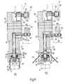
- Figure 1 shows a side view, with parts in section and parts removed for clarity, of a preferred embodiment of a product conveying line implementing the method according to the present invention;
- Figures 2 and 3 show a larger-scale detail of Figure 1 in two different operating positions;
- Figure 4 shows a larger-scale longitudinal section of a Figure 1 detail in two different operating positions.
-
-
Number 1 in Figure 1 indicates a line for conveyingproducts 2. -
Line 1 comprises aconveying device 3 for feeding a succession ofproducts 2 along a path P1 and in a given traveling direction D through a detectingstation 4, where the position ofproducts 2 alongdevice 3 is detected, and forfeeding products 2 to a pickup station 5 located downstream fromstation 4 along path P1 in the traveling direction ofproducts 2.Line 1 also comprises apickup device 6 in turn comprising a number ofgripping heads 7, which are movable at constant speed along a substantially circular path P2 tangent to path P1 at least at station 5, and each of which provides for picking up aproduct 2 at station 5 and feedingproduct 2 to a known machine (not shown). Finally,line 1 comprises atiming assembly 8, which, as explained in detail later on, acts ondevice 3 totime products 2 andheads 7 in relation to one another at station 5. - Conveying
device 3 comprises aconveyor belt 9 made of permeable material and looped about two transmission pulleys 10 (only one shown); and amotor 11 fordriving belt 9. More specifically,pulleys 10 define onbelt 9 anupper transportation branch 12 extending along path P1 and throughstations 4 and 5; and alower return branch 13 along which anoutput pulley 14 ofmotor 11 is maintainedcontacting belt 9 by twotensioning pulleys 15. -
Device 3 also comprises aretaining device 16 for securingproducts 2 in contact withbranch 12 ofbelt 9 and so preventingproducts 2 from slipping in relation tobelt 9, and which in turn comprises asuction chamber 17, which is located insidebelt 9, is connected to a known suction device (not shown) by aconduit 18, and has anupper wall 19 contactingbranch 12. - More specifically,
wall 19 extends for a given length L1 beneathbranch 12, comprises a number ofholes 20 arranged along the whole ofwall 19, and has a substantially triangular longitudinal section, so as to define, onbranch 12, a first horizontalflat portion 21, and a second downward-slopingflat portion 22 extending beneathstations 4 and 5. - Finally,
device 3 comprises arelease device 23 located at station 5 and for releasingproducts 2 frombelt 9 to enable pickup ofproducts 2 byheads 7.Device 23 comprises ashutter plate 24 housed insidechamber 17, and which is moved by alinear actuator 25 between a closed position (Figure 1) in whichplate 24contacts wall 19 to closeholes 20 and cut off suction at station 5, and an open position (Figures 2 and 3) in whichplate 24 is located a given distance fromwall 19 tofree holes 20, permit suction throughholes 20 andbelt 9, and so retain aproduct 2 at station 5 as described in detail later on. - In addition to
heads 7,pickup device 6 also comprises aconveyor wheel 26, which is rotated by a motor 27 at constant angular speed about anaxis 26a crosswise to direction D, and which feedsheads 7 along path P2 aboutaxis 26a, while at the same time imparting a given position to eachhead 7 by means of anorienting device 28 defined by anannular groove 29 extending aboutaxis 26a, and which also forms part ofdevice 6. - As shown in Figure 4, each
head 7 comprises abody 30 having anaxis 30a crosswise toaxis 26a, and connected in rotary and axially-fixed manner towheel 26 by apin 31 parallel toaxis 26a. Eachhead 7 also comprises atappet roller 32, which is engaged in rolling manner insidegroove 29, is fitted in rotary manner to the end of anarm 33 extending frombody 30 in a direction substantially parallel toaxis 30a, and cooperates withdevice 28 to so orientrespective head 7 that, in use, and at least during pickup of aproduct 2,axis 30a is positioned crosswise to slopingportion 22. - Each
head 7 also comprises agripping device 34 forgripping products 2, and in turn comprising twojaws 35, which are fitted to the free end ofbody 30, on either side ofaxis 30a, and which are rotated, by acontrol device 36 and about respective axes crosswise toaxis 30a, between a closed position (Figure 4a) in whichjaws 35 are parallel to each other and to axis 30a to gripproduct 2, and an open position (Figure 4b) in which at least the free ends ofjaws 35 are parted by a distance greater than the width of aproduct 2. -
Control device 36 comprises anactuating rod 37, which is movable alongaxis 30a inside arespective seat 38 formed inrespective head 7. At thebottom end 39,rod 37 comprises tworacks 40, each of which engages arespective toothed profile 41 formed onrespective jaw 35 to rotatejaw 35 about the respective axis; and, at thetop end 42opposite end 39,rod 37 comprises apin 43 integral withrod 37, extending crosswise toaxis 30a frombody 30 towardswheel 26, and fitted in rotary manner on its free end with twotappet rollers -
Roller 44 positively engages acam 46 extending aboutaxis 26a and for opening and closingjaws 35 by movingrod 37 insiderespective seat 38 and in opposition to aclosing spring 47 compressed between astop surface 48 ofseat 38 and ashoulder 49 ofrod 37 defined by the tworacks 40; androller 45 positively engages acam 50 located to the side ofcam 46 along path P2 and substantially facing pickup station 5. More specifically,cam 50 is movable by alinear actuator 51, and rotates about anaxis 50a, parallel toaxis 26a, between a withdrawn idle position (Figure 4a) in which it is positioned radially inwards ofcam 46, and an extracted position (Figure 4b) in which it projects radially with respect tocam 46 to engageroller 45,release roller 44 fromcam 46, and so preventjaws 35 from closing along pickup station 5. -
Timing assembly 8 comprises aphotocell 52 located at detectingstation 4 and for detecting the passage of aproduct 2, in particular of anend surface 2f ofproduct 2; and aphotocell 53 facingbranch 12 upstream fromphotocell 52 along path P1, and separated fromphotocell 52 by distance L1. Photocell 53 provides for determining that the length L2 of the succession ofproducts 2 is at least equal to length L1, so that, in use, a given number ofproducts 2 is always present betweenphotocells Assembly 8 also comprises acontrol unit 54, the inputs of which are connected tophotocells motor 11 ofconveyor belt 9, toactuator 25 ofshutter plate 24, and toactuator 51 ofmovable cam 50. - Operation of
line 1 will first be described with reference to oneproduct 2 and in the steady-state operating condition in which conveyingdevice 3feeds product 2 to pickup station 5 at a given speed V1, andpickup device 6feeds heads 7 through station 5 at constant speed. In this condition,plate 24 is set to the closed position, andcam 50 is set to the withdrawn idle position so thatjaws 35 ofheads 7 traveling through station 5 are set to the closed position and gripproduct 2 uponproduct 2 reaching station 5. - In the above steady-state operating condition, as
product 2 travels through detectingstation 4, photocell 52 detects the passage of leadingsurface 2f ofproduct 2 and supplies a signal tounit 54, which compares the signal from said encoder of motor 27 with the signal from photocell 52 to determine whetherproduct 2 andrespective gripping head 7 are in time with each other or not. Ifproduct 2 andrespective head 7 are in time with each other, belt 9feeds product 2 to station 5, where, by means ofjaws 35,respective head 7grips product 2 to feed it to said machine.Orienting device 28 sopositions body 30 ofhead 7 that, even before actual pickup, i.e. beforejaws 35grip product 2,respective axis 30a is positioned crosswise to slopingportion 22, andjaws 35 are positioned alongsideproduct 2 for a short distance upstream from station 5. - In the
event product 2 andrespective head 7 are not in time with each other, two situations are possible:product 2 is supplied to station 5 early with respect to the passage ofrespective head 7 through station 5; orproduct 2 is supplied to station 5 late with respect tohead 7. - If
product 2 is early with respect tohead 7,control unit 54 slows downmotor 11 to reduce speed V1 and so slow down supply ofproduct 2 to station 5. Conversely, ifproduct 2 is late,unit 54 acceleratesmotor 11 to increase speed V1 and so make up for the delay. Retainingdevice 16 ensures that, when decelerating or acceleratingbelt 9 as described above,product 2 is maintained contacting, and prevented from sliding along,belt 9; whileplate 24 in the closed position cuts off suction throughholes 20 at station 5 to enable pickup ofproduct 2 byrespective head 7. - If more than one
product 2, i.e. asuccession 55 ofproducts 2, is to be supplied to station 5, the above situations are repeated in the same way for eachproduct 2 traveling through detectingstation 4; and, by means of the signals from photocell 52 and said encoder,unit 54 constantly controls the traveling speed V1 ofbelt 9 for eachproduct 2 out of time in relation torespective head 7, to ensure eachproduct 2 is timed withrespective head 7, and eachhead 7 picks up arespective product 2. - Upon
photocell 53 detecting that the length L2 ofsuccession 55 is less than length L1, a signal is supplied by photocell 53 tounit 54, which immediately stopsmotor 11 to arrest the travel ofsuccession 55 towards station 5, and so operatesactuators plate 24 to the open position andcam 50 to the extracted position. - Due to the inertia of
belt 9, this will not be arrested immediately, so that thefirst product 2 insuccession 55 is arrested substantially at station 5 (Figure 2) where it is also retained by the suction no longer cut off throughholes 20 byplate 24. At this point,unit 54 reverses motor 11 (Figure 3) to invert the traveling direction ofproducts 2 along path P1 and so move at least thefirst product 2 insuccession 55 back by a given distance, upstream fromphotocell 52, equal to the distance to be traveled byfirst product 2 upon reactivation ofmotor 11, which occurs when length L2 ofsuccession 55 is made at least equal to length L1 by the supply offurther products 2 by a known feed device (not shown) located upstream from conveyingdevice 3, and by whichproducts 2 are fed ontobranch 12, are slid ontoportion 22, and are gradually compacted against theremaining products 2 insuccession 55. - In other words, to prevent the
first product 2, during the transient stage following reactivation ofmotor 11, from arriving at station 5 at a different speed fromheads 7, or from being shifted so far forward as to be skipped completely byheads 7,first product 2 insuccession 55 must be moved back said given distance while building up length L2 ofsuccession 55; which given distance is determined according to the characteristics ofmotor 11, and is controlled byphotocell 52 supplying a signal tounit 54 on detecting, in this case, therear end surface 2f offirst product 2. - During build-up as described above,
wheel 26 continues rotating aboutaxis 26a to feedheads 7 through station 5, and, as described previously, on nearing station 5,heads 7 are positioned withaxes 30a crosswise toportion 22, and withjaws 35 in the open position on either side ofproducts 2 close to station 5. Also, during build-up,unit 54shifts cam 50 into the extracted position to preventjaws 35 from being closed even at station 5, and so prevent thefirst products 2 from being gripped by mistake and damaged by the simultaneous action ofjaws 35, which tend to detach them frombelt 9, and the suction of retainingdevice 16, which tends to hold them onbelt 9. - On determining that length L2 is once more at least equal to length L1, photocell 53 supplies a further signal to
unit 54, which restartsmotor 11 to supplyproducts 2 to station 5. - Continuously varying the speed V1 at which
products 2 are supplied to station 5 therefore provides fortiming products 2 in relation to respective grippingheads 7 in a straightforward, relatively low-cost manner. Moreover, in addition to being handled carefully, as required by the fragile nature of their surface and structure,products 2 may vary in size within a fairly wide tolerance range, due to timing depending solely on the instant in which asurface 2f is detected byphotocell 52. Finally, openingjaws 35 during build-up provides for safeguarding the surface and structure of theproducts 2 supplied to said machine.
Claims (7)
- A method of conveying products (2), the method comprising the steps of feeding a product (2) along a first path (P1) by means of a conveying device (3) comprising drive means (11) for driving the conveying device (3), the first path (P1) extending through a pickup station (5) at which the product (2) is picked up; and feeding a gripping member (7) along a second path (P2) tangent to the first path (P1) at least at said pickup station (5); the method being characterized by comprising the further steps of securing the product (2) to said conveying device (3) in a given position via retaining means (16); detecting said given position via detecting means (52) located at a detecting station (4) upstream from said pickup station (5) along said first path (P1); emitting a position signal; regulating said drive means (11), on the basis of the position signal, so that said product (2) is fed to the pickup station (5) in time with said gripping member (7); and releasing said product (2) from said conveying device (3) via releasing means (23) located at the pickup station (5), to enable pickup of the product (2) by said gripping member (7).
- A method as claimed in Claim 2, characterized in that the product (2) forms part of a succession (55) of products (2); the method repeating, for each product (2) in said succession (55) of products (2), said steps of feeding the product (2) along said first path (P1); feeding at least one gripping member (7) along the second path (P2) through the pickup station (5); securing each product (2) to the conveying device (3) in a respective given position; detecting each position at said detecting station (4); emitting, for each detection, a position signal; regulating said drive means (11), on the basis of each position signal, so that each product (2) is fed to the pickup station (5) in time with a gripping member (7); and releasing each product (2) from said conveying device (3) via said releasing means (23), to enable pickup of the product (2).
- A method as claimed in Claim 2, characterized by comprising the further step of controlling a length (L2) of said succession (55) via control means (53) located along the first path (P1) at a given distance (L1) from said detecting station (4).
- A method as claimed in Claim 3, characterized by comprising the step of arresting said drive means (11) in the event said length (L2) is less than said given distance (L1); said releasing means (23) being disabled during the arresting step; and said drive means (11) subsequently being activated to move at least the first product (2) in the succession (55) back by a further given distance in relation to the pickup station (5).
- A method as claimed in Claim 4, characterized in that each said gripping member (7) comprises a gripping device (34) for gripping the respective product (2); the gripping device (34) being activated during the pickup of the relevant product (2).
- A method as claimed in Claim 5, characterized in that, during said arresting step, said gripping device (34) is disabled via disabling means (50) located at said pickup station (5).
- A method as claimed in any one of the foregoing Claims, characterized in that, during the pickup of the product (2), each gripping member (7) is so oriented as to be positioned with a respective axis (30a) crosswise to the first path (P1).
Applications Claiming Priority (2)
| Application Number | Priority Date | Filing Date | Title |
|---|---|---|---|
| ITBO960194 | 1996-04-09 | ||
| IT96BO000194A IT1285666B1 (en) | 1996-04-09 | 1996-04-09 | METHOD FOR THE ADVANCE OF PRODUCTS |
Publications (2)
| Publication Number | Publication Date |
|---|---|
| EP0801014A1 EP0801014A1 (en) | 1997-10-15 |
| EP0801014B1 true EP0801014B1 (en) | 2001-07-18 |
Family
ID=11341330
Family Applications (1)
| Application Number | Title | Priority Date | Filing Date |
|---|---|---|---|
| EP97105695A Expired - Lifetime EP0801014B1 (en) | 1996-04-09 | 1997-04-07 | Product conveying method |
Country Status (6)
| Country | Link |
|---|---|
| US (1) | US5881860A (en) |
| EP (1) | EP0801014B1 (en) |
| JP (1) | JP3790007B2 (en) |
| DE (1) | DE69705661T2 (en) |
| ES (1) | ES2160864T3 (en) |
| IT (1) | IT1285666B1 (en) |
Cited By (2)
| Publication number | Priority date | Publication date | Assignee | Title |
|---|---|---|---|---|
| EP2110327A1 (en) | 2008-04-18 | 2009-10-21 | THEEGARTEN-PACTEC GMBH & CO. KG | Product supply and corresponding method |
| DE102022109941A1 (en) | 2022-04-25 | 2023-10-26 | Theegarten-Pactec Gmbh & Co. Kg | Method and device for separating and processing small-sized products |
Families Citing this family (14)
| Publication number | Priority date | Publication date | Assignee | Title |
|---|---|---|---|---|
| DE19715949A1 (en) * | 1997-04-16 | 1998-10-22 | Pactec Verpackungsmaschinen Fa | Process for separating small-sized objects and separating device |
| EP0885823A1 (en) * | 1997-06-20 | 1998-12-23 | Klöckner Hänsel Tevopharm B.V. | Conveyor device for accelerating a series of products |
| US6216848B1 (en) * | 1999-04-09 | 2001-04-17 | Profold, Inc. | Vacuum table conveying apparatus and associated methods |
| US6575450B2 (en) | 2001-01-30 | 2003-06-10 | Lockheed Martin Corporation | Singulation mechanism |
| ITBO20020175A1 (en) * | 2002-04-03 | 2003-10-03 | Carle & Montanari Spa | CHOCOLATE AND SIMILAR PRODUCTS FEEDING DEVICE |
| DE10217899A1 (en) * | 2002-04-22 | 2003-11-06 | Theegarten Pactec Gmbh & Co Kg | Device and method for stacking small items |
| DE102007011060A1 (en) * | 2007-03-07 | 2008-09-11 | Sig Technology Ag | Method and apparatus for blow molding containers |
| ITFI20110218A1 (en) * | 2011-10-07 | 2013-04-08 | Kpl Packaging Spa | "METHOD AND DEVICE FOR FEEDING PRODUCTS WITH A PROCESSING STATION" |
| EP3129295B1 (en) * | 2014-04-10 | 2018-03-28 | Cmfima S.R.L. | Adjustment assembly for packaging machines and the like |
| DE202016004428U1 (en) * | 2016-07-20 | 2017-10-23 | Barry-Wehmiller Papersystems, Inc. | Device for applying data carriers to a carrier web |
| CN106829464A (en) * | 2017-04-06 | 2017-06-13 | 李家凌 | A kind of finished product extraction mechanism in Lamp cup lamp bead and the continuous fixing device of capping |
| DE102017115337A1 (en) * | 2017-07-10 | 2019-01-10 | Sig Technology Ag | Method and device for gripping and retaining spout segments having a flange and a screw cap for subsequent application to packages |
| DE102018217776A1 (en) | 2018-10-17 | 2020-04-23 | Krones Ag | Graduation change star for transporting and transferring containers |
| FR3121858A1 (en) * | 2021-04-19 | 2022-10-21 | Egg-Chick Automated Technologies | Object Transfer Apparatus |
Family Cites Families (10)
| Publication number | Priority date | Publication date | Assignee | Title |
|---|---|---|---|---|
| US3075630A (en) * | 1959-03-09 | 1963-01-29 | Mathews Conveyer Co | Article synchronizing conveyer |
| US3570647A (en) * | 1969-06-13 | 1971-03-16 | Corning Glass Works | Loading apparatus |
| GB1455569A (en) * | 1973-01-30 | 1976-11-17 | Unigate Ltd | Container checking |
| GB2129754A (en) * | 1982-11-05 | 1984-05-23 | Baker Perkins Holdings Plc | Feeding apparatus and the method |
| JPS61178315A (en) * | 1985-02-01 | 1986-08-11 | Rheon Autom Mach Co Ltd | Transfer loader for raw material or the like |
| US4746007A (en) * | 1986-02-20 | 1988-05-24 | Quipp Incorporated | Single gripper conveyor system |
| CH672293A5 (en) * | 1987-03-23 | 1989-11-15 | Sig Schweiz Industrieges | |
| IT1217694B (en) * | 1988-05-23 | 1990-03-30 | Francesco Canziani | METHOD FOR THE CONTROL OF THE EXACT POSITIONING OF THE OBJECTS TO BE SORTED IN AN AUTOMATIC SORTING SYSTEM |
| US5097939A (en) * | 1989-11-03 | 1992-03-24 | Shanklin Corporation | Synchronous position product feed system |
| IT1266231B1 (en) * | 1993-01-29 | 1996-12-27 | Azionaria Costruzioni Acma Spa | WRAPPING METHOD AND MACHINE, PARTICULARLY FOR FOOD PRODUCTS SUCH AS CHOCOLATES AND SIMILAR. |
-
1996
- 1996-04-09 IT IT96BO000194A patent/IT1285666B1/en active IP Right Grant
-
1997
- 1997-04-07 DE DE69705661T patent/DE69705661T2/en not_active Expired - Lifetime
- 1997-04-07 EP EP97105695A patent/EP0801014B1/en not_active Expired - Lifetime
- 1997-04-07 ES ES97105695T patent/ES2160864T3/en not_active Expired - Lifetime
- 1997-04-08 US US08/824,684 patent/US5881860A/en not_active Expired - Fee Related
- 1997-04-09 JP JP09117397A patent/JP3790007B2/en not_active Expired - Fee Related
Cited By (3)
| Publication number | Priority date | Publication date | Assignee | Title |
|---|---|---|---|---|
| EP2110327A1 (en) | 2008-04-18 | 2009-10-21 | THEEGARTEN-PACTEC GMBH & CO. KG | Product supply and corresponding method |
| DE102022109941A1 (en) | 2022-04-25 | 2023-10-26 | Theegarten-Pactec Gmbh & Co. Kg | Method and device for separating and processing small-sized products |
| EP4269293A1 (en) | 2022-04-25 | 2023-11-01 | Theegarten-Pactec GmbH & Co. KG | Method and device for separating and processing small-piece products |
Also Published As
| Publication number | Publication date |
|---|---|
| ES2160864T3 (en) | 2001-11-16 |
| JPH1035613A (en) | 1998-02-10 |
| DE69705661T2 (en) | 2002-09-05 |
| US5881860A (en) | 1999-03-16 |
| DE69705661D1 (en) | 2001-08-23 |
| ITBO960194A0 (en) | 1996-04-09 |
| JP3790007B2 (en) | 2006-06-28 |
| ITBO960194A1 (en) | 1997-10-09 |
| EP0801014A1 (en) | 1997-10-15 |
| IT1285666B1 (en) | 1998-06-18 |
Similar Documents
| Publication | Publication Date | Title |
|---|---|---|
| EP0801014B1 (en) | Product conveying method | |
| CA2619461C (en) | Systems and methods for providing an improved timing conveyor | |
| US5522692A (en) | Device and method for palletizing unstable articles | |
| US7926664B2 (en) | Apparatus for transferring products | |
| US7555881B2 (en) | Method and unit for feeding products to a group-forming unit | |
| US20120198795A1 (en) | Packaging machine and method | |
| US7730697B2 (en) | Automatic machine for making filter bags for infusion products | |
| US5419425A (en) | Apparatus and method for loading lumber onto a high-speed lugged transfer deck | |
| US5020655A (en) | Article group-segregating apparatus and method | |
| EP0806388B1 (en) | Method and unit for forming and conveying groups of products | |
| US3575276A (en) | Direction changing in conveyance systems | |
| US6308817B1 (en) | Method and unit for forming a group of products on a cartoning machine | |
| US6209706B1 (en) | Article grouping and transferring system | |
| US6213284B1 (en) | Method and unit for transferring articles | |
| US5012916A (en) | Article group-segregating apparatus and method | |
| CA1280774C (en) | Feed conveyor for machine for forming leads of electronic components | |
| EP0413997B1 (en) | Device for feeding products from a supply unit to a receiving unit | |
| JPH11513648A (en) | Can lid supply device | |
| US20040238325A1 (en) | Method and machine for transferring packets | |
| US11905123B2 (en) | Apparatus and method for varying the pitch between moving articles | |
| EP0987180B1 (en) | A method of controlling the operation of a packaging line automatically | |
| EP1503939B1 (en) | Feeding device of chocolates and similar products |
Legal Events
| Date | Code | Title | Description |
|---|---|---|---|
| PUAI | Public reference made under article 153(3) epc to a published international application that has entered the european phase |
Free format text: ORIGINAL CODE: 0009012 |
|
| AK | Designated contracting states |
Kind code of ref document: A1 Designated state(s): CH DE ES GB IT LI |
|
| 17P | Request for examination filed |
Effective date: 19980319 |
|
| GRAG | Despatch of communication of intention to grant |
Free format text: ORIGINAL CODE: EPIDOS AGRA |
|
| 17Q | First examination report despatched |
Effective date: 20001201 |
|
| GRAG | Despatch of communication of intention to grant |
Free format text: ORIGINAL CODE: EPIDOS AGRA |
|
| GRAH | Despatch of communication of intention to grant a patent |
Free format text: ORIGINAL CODE: EPIDOS IGRA |
|
| GRAH | Despatch of communication of intention to grant a patent |
Free format text: ORIGINAL CODE: EPIDOS IGRA |
|
| GRAA | (expected) grant |
Free format text: ORIGINAL CODE: 0009210 |
|
| AK | Designated contracting states |
Kind code of ref document: B1 Designated state(s): CH DE ES GB IT LI |
|
| ITF | It: translation for a ep patent filed |
Owner name: STUDIO TORTA S.R.L. |
|
| REG | Reference to a national code |
Ref country code: CH Ref legal event code: NV Representative=s name: PATENTANWALTSBUERO FELDMANN AG Ref country code: CH Ref legal event code: EP |
|
| REF | Corresponds to: |
Ref document number: 69705661 Country of ref document: DE Date of ref document: 20010823 |
|
| PG25 | Lapsed in a contracting state [announced via postgrant information from national office to epo] |
Ref country code: DE Free format text: LAPSE BECAUSE OF FAILURE TO SUBMIT A TRANSLATION OF THE DESCRIPTION OR TO PAY THE FEE WITHIN THE PRESCRIBED TIME-LIMIT Effective date: 20011019 |
|
| REG | Reference to a national code |
Ref country code: ES Ref legal event code: FG2A Ref document number: 2160864 Country of ref document: ES Kind code of ref document: T3 |
|
| REG | Reference to a national code |
Ref country code: GB Ref legal event code: IF02 |
|
| PLBE | No opposition filed within time limit |
Free format text: ORIGINAL CODE: 0009261 |
|
| STAA | Information on the status of an ep patent application or granted ep patent |
Free format text: STATUS: NO OPPOSITION FILED WITHIN TIME LIMIT |
|
| 26N | No opposition filed | ||
| PGFP | Annual fee paid to national office [announced via postgrant information from national office to epo] |
Ref country code: GB Payment date: 20060424 Year of fee payment: 10 |
|
| PGFP | Annual fee paid to national office [announced via postgrant information from national office to epo] |
Ref country code: ES Payment date: 20060426 Year of fee payment: 10 |
|
| REG | Reference to a national code |
Ref country code: CH Ref legal event code: PFA Owner name: AZIONARIA COSTRUZIONI MACCHINE AUTOMATICHE-A.C.M. Free format text: AZIONARIA COSTRUZIONI MACCHINE AUTOMATICHE-A.C.M.A.-S.P.A.#VIA CRISTOFORO COLOMBO 1#I-40131 BOLOGNA (IT) -TRANSFER TO- AZIONARIA COSTRUZIONI MACCHINE AUTOMATICHE-A.C.M.A.-S.P.A.#VIA CRISTOFORO COLOMBO 1#I-40131 BOLOGNA (IT) |
|
| GBPC | Gb: european patent ceased through non-payment of renewal fee |
Effective date: 20070407 |
|
| PG25 | Lapsed in a contracting state [announced via postgrant information from national office to epo] |
Ref country code: GB Free format text: LAPSE BECAUSE OF NON-PAYMENT OF DUE FEES Effective date: 20070407 |
|
| REG | Reference to a national code |
Ref country code: ES Ref legal event code: FD2A Effective date: 20070409 |
|
| PG25 | Lapsed in a contracting state [announced via postgrant information from national office to epo] |
Ref country code: ES Free format text: LAPSE BECAUSE OF NON-PAYMENT OF DUE FEES Effective date: 20070409 |
|
| PGFP | Annual fee paid to national office [announced via postgrant information from national office to epo] |
Ref country code: DE Payment date: 20160427 Year of fee payment: 20 Ref country code: CH Payment date: 20160427 Year of fee payment: 20 |
|
| PGFP | Annual fee paid to national office [announced via postgrant information from national office to epo] |
Ref country code: IT Payment date: 20160421 Year of fee payment: 20 |
|
| REG | Reference to a national code |
Ref country code: DE Ref legal event code: R071 Ref document number: 69705661 Country of ref document: DE |
|
| REG | Reference to a national code |
Ref country code: CH Ref legal event code: PL |