EP0801504A2 - Method for encoding a contour of an object in a video signal by using a contour motion estimation technique - Google Patents
Method for encoding a contour of an object in a video signal by using a contour motion estimation technique Download PDFInfo
- Publication number
- EP0801504A2 EP0801504A2 EP19960304817 EP96304817A EP0801504A2 EP 0801504 A2 EP0801504 A2 EP 0801504A2 EP 19960304817 EP19960304817 EP 19960304817 EP 96304817 A EP96304817 A EP 96304817A EP 0801504 A2 EP0801504 A2 EP 0801504A2
- Authority
- EP
- European Patent Office
- Prior art keywords
- contour
- current
- reconstructed
- differential
- vertex
- Prior art date
- Legal status (The legal status is an assumption and is not a legal conclusion. Google has not performed a legal analysis and makes no representation as to the accuracy of the status listed.)
- Granted
Links
Images


Classifications
-
- G—PHYSICS
- G06—COMPUTING; CALCULATING OR COUNTING
- G06T—IMAGE DATA PROCESSING OR GENERATION, IN GENERAL
- G06T9/00—Image coding
- G06T9/20—Contour coding, e.g. using detection of edges
-
- H—ELECTRICITY
- H04—ELECTRIC COMMUNICATION TECHNIQUE
- H04N—PICTORIAL COMMUNICATION, e.g. TELEVISION
- H04N19/00—Methods or arrangements for coding, decoding, compressing or decompressing digital video signals
- H04N19/50—Methods or arrangements for coding, decoding, compressing or decompressing digital video signals using predictive coding
- H04N19/503—Methods or arrangements for coding, decoding, compressing or decompressing digital video signals using predictive coding involving temporal prediction
- H04N19/51—Motion estimation or motion compensation
- H04N19/537—Motion estimation other than block-based
- H04N19/543—Motion estimation other than block-based using regions
-
- H—ELECTRICITY
- H04—ELECTRIC COMMUNICATION TECHNIQUE
- H04N—PICTORIAL COMMUNICATION, e.g. TELEVISION
- H04N19/00—Methods or arrangements for coding, decoding, compressing or decompressing digital video signals
- H04N19/20—Methods or arrangements for coding, decoding, compressing or decompressing digital video signals using video object coding
Definitions
- the present invention relates to a method for encoding a video signal; and, more particularly, to a method capable of effectively encoding a contour of an object contained in a video signal, thereby reducing the amount of data to be transmitted.
- One of such techniques for encoding video signals for a low bit-rate encoding system is the so-called object-oriented analysis-synthesis coding technique( see Michael Hötter, "Object-Oriented Analysis-Synthesis Coding Based on Moving Two-Dimensional Objects", Signal Processing: Image Communication 2 , 409-428(December, 1990)).
- an input video image is divided into objects; and three sets of parameters for defining the motion, contour and pixel data of each object are processed through different encoding channels.
- contour information is important for the analysis and synthesis of the object shape.
- a classical coding method for representing the contour information is a chain coding method.
- the chain coding method requires a substantial amount of bits for the representation thereof, although there is no loss in the contour information.
- DST discrete sine transform
- the N sample points are equi-distanced on each line segment and each of the approximation errors represents the distance between each of the N sample points and the contour. Thereafter, sets of DST coefficients are generated by performing a one-dimensional DST operation on each set of approximation errors.
- a primary object of embodiments of the invention to provide an improved method for encoding a contour of an object in a video signal, which is capable of further reducing the amount of transmission data through the use of a contour motion estimation technique.
- a method for encoding a contour of an object expressed in a digital video signal comprising the steps of: (a) detecting a boundary of the object within the current frame to generate a current contour, wherein the current contour provides current contour information for tracing the boundary of the object in the current frame, the current contour information including position data of the pixels along the boundary of the object; (b) storing a reconstructed previous contour, wherein the reconstructed previous contour provides reconstructed previous contour information for tracing the boundary of the object in the previous frame; (c) determining a motion vector by detecting a movement of the reconstructed previous contour that gives a best matching between the current and the reconstructed previous contours when the reconstructed previous contour is moved to overlap with the current contour, and generating the motion vector and a predicted current contour, wherein the motion vector represents a displacement between the reconstructed previous contour and the predicted current contour
- the contour encoding apparatus comprises two coding channels, i.e., intra-coding channel 25 and inter-coding channel 35, capable of selectively encoding the contour of the object in response to a channel selection signal CS of a logic high or a logic low produced by a system controller(not shown), wherein the intra-coding channel 25 employs a polygonal approximation and a discrete sine transform(DST) to encode the contour, and the inter-coding channel 35 encodes the contour by using a contour motion estimation technique together with the polygonal approximation and the DST.
- intra-coding channel 25 employs a polygonal approximation and a discrete sine transform(DST) to encode the contour
- DST discrete sine transform
- an input digital video signal is fed, as a current frame signal, to a contour detector 10.
- the contour detector 10 detects a boundary or contour of an object in a current frame and generates a current contour, wherein the current contour provides current contour information for tracing the boundary of the object in the current frame, the current contour information including position data of the pixels along the boundary of the object in the current frame.
- the current contour representing the contour of the object is inputted to a pre-processing block 15.
- the pre-processing block 15 removes a contour consisting of a few of pixels in order to improve a coding efficiency and exclude noise effect.
- the pre-processed current contour from the pre-processing block 15 is provided via a line L10 to a first switch 20 which serves to selectively provide the pre-processed current contour on the line L10 to the intra-coding channel 25 or inter-coding channel 35 in response to the CS.
- the first switch 20 supplies the pre-processed current contour on the line L10 to the intra-coding channel 25 through a line L12 if the CS generated from the system controller is, e.g., a logic low; otherwise, it relays the pre-processed current contour to the inter-coding channel 35 through a line L14.
- the intra-coding channel 25 encodes the contour on the line L12 based on the polygonal approximation and the DST to thereby provide an encoded contour signal to a second switch 40 through a line L16; and also provides the reconstructed contour as a previous contour to a frame memory 30 for the storage thereof. Details of the intra-coding channel 25 will be described hereafter with reference to Figs. 2, 4A to 4C, 5A and 5B.
- a predicted current contour and a motion vector are generated by predicting the current contour based on the pre-processed current contour on the line L14 and the reconstructed previous contour retrieved from the frame memory 30, wherein the motion vector represents a spatial displacement between the reconstructed previous contour and the predicted current contour.
- the differential contour and the motion vector are encoded by using the polygonal approximation and the DST, thereby providing an encoded contour signal to the second switch 40 through a line L18; and also provides the reconstructed contour as the previous contour to the frame memory 30 for the storage thereof.
- the inter-coding channel 35 will be described in detail hereafter with reference to Figs. 3 and 6.
- the second switch 40 selectively outputs the encoded contour signal from the intra-coding channel 25 or inter-coding channel 35 in response to the CS from the system controller(not shown).
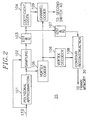
- FIG. 2 there is illustrated a detailed block diagram of the intra-coding channel 25 shown in Fig. 1.
- the pre-processed current contour on the line L12 from the first switch 20 shown in Fig. 1 is inputted to a polygonal approximation block 101 and a sampling circuit 102.
- a pre-processed current contour is approximated by a polygonal approximation technique.
- the polygonal approximation of the object shape is achieved through the use of a conventional approximation algorithm for fitting the contour with a plurality of line segments.
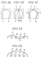
- FIG. 4A to 4C there is illustrated a segmentation process for an exemplary pre-processed current contour 5 according to the polygonal approximation technique.
- two starting vertex points are selected. If the pre-processed current contour is of an open loop, two end points, e.g., A and B as shown in Fig. 4A, are selected as the starting vertex points. On the other hand, if the pre-processed current contour is in the form of a closed loop, two farthest points on the contour are selected as the starting vertex points. And then, the farthest point on the contour from a line segment AB is determined. If the distance D max between the farthest point, e.g., C, and the line segment AB is greater than a predetermined threshold value, the point C becomes a vertex point. This procedure is repeated until the D max for each segment becomes smaller than the predetermined threshold value.
- the number of vertex points depends on the predetermined threshold value As can be seen from Figs. 4A to 4C, the representation of the contour by line segments becomes more accurate as the predetermined threshold value becomes smaller, at the expense of coding efficiency.
- vertex information representing the positions of the determined vertex points, e.g., A, B, C, D and E, of the pre-processed current contour 5 is provided from the polygonal approximation block 101 to the sampling circuit 102 and a vertex coder 105.
- the sampling circuit 102 selects N sample points for each line segment and calculates an approximation error at each of the N sample points on each line segment based on the vertex information and the pre-processed current contour data, wherein the N sample points are equi-distanced on each line segment between two vertex points with N being an integer.
- the approximation error represents the distance between a line segment joining two vertex points and the contour segment between the two vertex points.
- Figs. 5A and 5B illustrate exemplary diagrams representing approximation errors between line segments and corresponding contour segments, wherein Fig. 5A depicts approximation errors between the line segment AD and its corresponding contour segment and Fig. 5B shows approximation errors between the line segment DC and its corresponding contour segment.
- Each of the errors d1 to d4 or d1' to d4' represents the distance from each sample point S1 to S4 on the line segment AD or S1' to S4' on the line segment DC to the corresponding contour segment.
- the approximation errors for the vertex points are all "zeros", since all the vertex points are positioned on the contour.
- the approximation errors calculated by the sampling circuit 102 are supplied to a DST & quantization(Q) block 103.
- the DST & Q block 103 performs one-dimensional DST operation on the set of the approximation errors for each of the line segments to produce a set of DST coefficients corresponding to each set of the approximation errors, the approximation errors for each set including errors for N sample points and two vertex points of each line segment; and quantizes each set of DST coefficients to provide a set of quantized DST coefficients corresponding to each set of DST coefficients to a coefficient coder 104 and an inverse discrete sine transform(IDST) and inverse quantization(IQ) block 107.
- the quantized DST coefficients are encoded, e.g., by using a binary arithmetic code of JPEG(Joint Picture Experts Group), and the encoded quantized DST coefficients are then transmitted to a channel coder 109.
- the vertex coder 105 encodes the vertex information representing the positions of the vertex points by using, e.g., a conventional syntax arithmetic code or the binary arithmetic code, and provides the coded vertex information to a vertex decode, 106 and the channel coder 109.
- the channel coder 109 encodes the coded vertex information together with the encoded quantized DST coefficients and provides an encoded contour signal comprising the coded vertex information and the encoded quantized DST coefficients to the second switch 40 shown in Fig. 1.
- the IDST & IQ block 107 performs IDST and IQ operations on each set of the encoded quantized DST coefficients to provide a set of reconstructed approximation errors for each line segment to a contour reconstruction block 108.
- the vertex decoder 106 decodes the coded vertex information from the vertex coder 105 to thereby provide the reconstructed vertex information to the contour reconstruction block 108.
- the contour is reconstructed based on the reconstructed vertex information from the vertex decoder 106 and each set of the reconstructed approximation errors for each of the line segments from the IDST & IQ block 107. Thereafter, the reconstructed contour is stored as the previous contour in the frame memory 30 shown in Fig. 1.
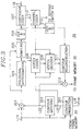
- Fig. 3 illustrates a detailed block diagram of the inter-coding channel 35 shown in Fig. 1, which incorporates a polygonal approximation block 204, a sampling circuit 205, a DST & Q block 206, a coefficient coder 207, a channel coder 213, an IDST & IQ block 210, and a contour reconstruction block 211 performing the same function as the corresponding elements contained in the intra-coding channel 25.
- the pre-processed current contour on the line L14 from the first switch 20 shown in Fig. 1 is supplied to a contour prediction block 201, a contour matching block 202 and a subtractor 203.
- the contour prediction block 201 the current contour and the reconstructed previous contour retrieved from the frame memory 30 shown in Fig. 1 are processed to predict the current contour, thereby generating the predicted current contour onto a line L20 and the motion vector representing the spatial displacement between the reconstructed previous contour and the predicted current contour onto a line L18.
- the motion vector is determined by finding a movement of the reconstructed previous contour that gives best matching between the pre-processed current contour and the reconstructed previous contour when the reconstructed previous contour is moved to overlap with the pre-processed current contour, wherein the matching includes the case where the deviation between corresponding pixels is one pixel position.
- the predicted current contour on the line L20 is overlapped with the pre-processed current contour on the line L14 at the contour matching block 202 and a matched contour representing an overlapped contour portion therebetween is generated onto a line L22.
- the matched contour on the line L22 is subtracted from the pre-processed current contour on the line L14 at the subtractor 203, and a differential contour denoting the differential contour portion between the pre-processed current contour and the matched contour is dispatched to the polygonal approximation block 204 and the sampling circuit 205.
- vertex points are determined by fitting the differential contour with a plurality of line segments. Thereafter, the vertex information representing the positions of the determined vertex points is provided to the sampling circuit 205 and a vertex coder 208 of the present invention.
- the sampling circuit 205 selects N sample points for each line segment and calculates an approximation error at each of the N sample points on each line segment based on the vertex information and the differential contour.
- the approximation errors calculated by the sampling circuit 205 are provided to the DST & Q block 206.
- the DST & Q block 206 performs the one-dimensional DST operation on the set of the approximation errors for each line segment to produce a set of DST coefficients corresponding to each set of the approximation errors; and quantizes each set of the DST coefficients to provide a set of quantized DST coefficients corresponding to each set of the DST coefficients to the coefficient coder 207 and the IDST & IQ block 210.
- the quantized DST coefficients are encoded together with the motion vector on the line L18 from the contour prediction block 201, e.g., by using the binary arithmetic code.
- the encoded digital signal comprising the encoded quantized DST coefficients and the motion vector is transmitted from the coefficient coder 207 to the channel coder 213.
- the vertex coder 208 encodes the vertex points selected from the polygonal approximation block 204 by using the displacement from pixel positions on the predicted current contour on the line L20 from the contour prediction block 201, or the displacement from the previously encoded vertex points.
- FIG. 6 there is illustrated an exemplary diagram for explaining a vertex coding scheme embodying the present invention.
- an index is assigned to each pixel on the predicted current contour 7 starting from a selected pixel. If the predicted current contour is of an open loop, one of the two end points thereof, e.g., E A and E B , which has a smaller x-component is selected as a starting point. In this example, E A is selected as the starting point. On the other hand, if the predicted current contour is in the form of a closed loop, a pixel having the smallest x-component on the contour is selected as the starting point. And then, the vertex points, e.g., E A and V1 to V3 obtained by performing the polygonal approximation for the differential contour 6 are encoded in accordance with the present invention.
- a circle having a predetermined radius R and a vertex point to be coded at the center thereof includes at least one pixel on the predicted current contour 7, a displacement between the vertex point and a closest pixel to the vertex point among the pixels included in the circle and the index corresponding to the closest pixel are encoded by using, e.g., the binary arithmetic code; otherwise, a displacement between a previously encoded vertex point and the vertex point is encoded.
- the vertex point V 1 is encoded by using an index corresponding to a closest pixel to V1 in the circle C 1 and a displacement therebetween since the circle C 1 having the predetermined radius R and the V1 at the center thereof includes pixels on the predicted current contour 7, while the vertex point V 2 is encoded by using a displacement between V 2 and the previously encoded vertex point, e.g., V 1 since non of the pixels on the predicted current contour 7 is contained in the circle C 2 having the predetermined radius R and the V 2 at the center thereof.
- the vertex points E A and V 3 being two end points of the differential contour 6 are encoded by using indexes corresponding thereto since they are located on the predicted current contour 7.
- the coded vertex information is provided from the vertex coder 208 to the channel coder 213 and the vertex decoder 209.
- the channel coder 213 encodes the coded vertex information together with the encoded digital signal comprising the encoded quantized DST coefficients and the motion vector, and provides the encoded contour signal to the second switch 40 shown in Fig. 1.
- the IDST & IQ block 210 performs IDST and IQ operations on each set of the quantized DST coefficients to provide a set of reconstructed approximation errors for each line segment to the contour reconstruction block 211.
- the vertex decoder 209 generates reconstructed vertex information through the use of the predicted current contour on the line L20 from the contour prediction block 201.
- the contour signal is reconstructed based on the reconstructed vertex information from the vertex decoder 209 and each set of the reconstructed approximation errors for each of the line segments from the IDST & ID block 210. Thereafter, at an adder 212, the reconstructed contour is added to the matched contour on the line L22 from the contour matching block 202 to produce a reconstructed contour.
- the reconstructed contour is stored as the previous contour in the frame memory 30 shown in Fig. 1.
- embodiments of the present invention effectively encode the contour of an object expressed in a video signal by using the contour motion estimation technique, thereby reducing the amount of data to be transmitted.
Abstract
Description
- The present invention relates to a method for encoding a video signal; and, more particularly, to a method capable of effectively encoding a contour of an object contained in a video signal, thereby reducing the amount of data to be transmitted.
- In digital television systems such as video-telephone, teleconference and high definition television systems, a large amount of digital data is needed to define each video frame signal since a video line signal in the video frame signal comprises a sequence of digital data referred to as pixel values. Since, however, the available frequency bandwidth of a conventional transmission channel is limited, in order to transmit the large amount of the digital data therethrough, it is inevitable to compress or reduce the volume of data through the use of various data compression techniques, especially, in the case of such low bit-rate video signal encoders as video-telephone and teleconference system.
- One of such techniques for encoding video signals for a low bit-rate encoding system is the so-called object-oriented analysis-synthesis coding technique(see Michael Hötter, "Object-Oriented Analysis-Synthesis Coding Based on Moving Two-Dimensional Objects", Signal Processing: Image Communication 2, 409-428(December, 1990)).
- According to the object-oriented analysis-synthesis coding technique, an input video image is divided into objects; and three sets of parameters for defining the motion, contour and pixel data of each object are processed through different encoding channels.
- In processing a contour of an object, contour information is important for the analysis and synthesis of the object shape. A classical coding method for representing the contour information is a chain coding method. The chain coding method, however, requires a substantial amount of bits for the representation thereof, although there is no loss in the contour information.
- To overcome the drawback, therefore, there have been proposed several methods to encode the contour information such as a polygonal approximation and a B-spline approximation. One of the disadvantages in the polygonal approximation is the roughness of the representation of the contour. The B-spline approximation is, on the other hand, capable of representing the contour more precisely; however, it requires a high-order polynomial to reduce the approximation error. The B-spline approximation technique, however, results in an increased overall computational complexity of the video encoder.
- One of the techniques introduced to ameliorate such problems associated with the rough representation of the contour and the increased computational complexity in the above approximation approaches is a contour approximation technique employing a discrete sine transform(DST).
- In an apparatus which adopts the contour approximation technique based on the polygonal approximation and the DST, as disclosed in a commonly owned copending application, EPC-Application No. 95 105 653.0, entitled "A CONTOUR APPROXIMATION APPARATUS FOR REPRESENTING A CONTOUR OF AN OBJECT", a number of vertex points are determined and the contour of an object is approximated through the use of polygonal approximation for fitting the contour by line segments. And, N sample points for each line segment are selected and an approximation error at each of the N sample points located on each line segment is sequentially calculated in order to obtain a set of approximation errors for each line segment. The N sample points are equi-distanced on each line segment and each of the approximation errors represents the distance between each of the N sample points and the contour. Thereafter, sets of DST coefficients are generated by performing a one-dimensional DST operation on each set of approximation errors.
- Even though it is possible to remedy the rough representation and computational complexity, and somewhat reduce the volume of transmission data through the use of the aforementioned DST based contour approximation, it still remains desirable to further reduce the volume of transmission data in order to successfully implement a low-bit rate codec system having, e.g., a 64 kb/s transmission channel bandwidth.
- It is, therefore, a primary object of embodiments of the invention to provide an improved method for encoding a contour of an object in a video signal, which is capable of further reducing the amount of transmission data through the use of a contour motion estimation technique.
- In accordance with one aspect of the invention, there is provided a method for encoding a contour of an object expressed in a digital video signal, the digital video signal having a plurality of frames including a current frame and a previous frame, comprising the steps of: (a) detecting a boundary of the object within the current frame to generate a current contour, wherein the current contour provides current contour information for tracing the boundary of the object in the current frame, the current contour information including position data of the pixels along the boundary of the object; (b) storing a reconstructed previous contour, wherein the reconstructed previous contour provides reconstructed previous contour information for tracing the boundary of the object in the previous frame; (c) determining a motion vector by detecting a movement of the reconstructed previous contour that gives a best matching between the current and the reconstructed previous contours when the reconstructed previous contour is moved to overlap with the current contour, and generating the motion vector and a predicted current contour, wherein the motion vector represents a displacement between the reconstructed previous contour and the predicted current contour, the predicted current contour representing a contour shifted from the reconstructed previous contour by the motion vector; (d) overlapping the predicted current contour with the current contour to thereby provide a matched contour representing an overlapped contour portion therebetween; (e) generating a differential contour by subtracting the matched contour from the current contour, the differential contour denoting the differential contour portion between the current and the matched contours; (f) determining a number of vertex points on the differential contour; (g) providing a polygonal approximation of the differential contour by fitting the differential contour with a multiplicity of line segments, to thereby generate vertex information representing the positions of the vertex points of the differential contour, each of the line segments joining two neighboring vertex points; (h) providing N sample points for each of the line segments and calculating an error for each of the N sample points on each of the line segments to produce a set of errors for each of the line segments, wherein said N sample points are equi-distanced on each of the line segments and each set of errors represents the distance between said each of the N sample points and the differential contour; (i) transforming the set of errors for each of the line segments into a set of discrete sine transform coefficients corresponding thereto; (j) converting the set of discrete sine transform coefficients into a set of quantized discrete sine transform coefficients corresponding thereto; (k) encoding the motion vector and the set of quantized discrete sine transform coefficients for each set of discrete sine transform coefficients; (l) encoding the vertex information based on the predicted current contour, to thereby provide encoded vertex information; (m) decoding the encoded vertex information based on the predicted current contour, thereby providing decoded vertex information; (n) converting the set of quantized discrete sine transform coefficients for each set of discrete sine transform coefficients into a set of reconstructed discrete sine transform coefficients; (o) converting the set of reconstructed discrete sine transform coefficients into a set of reconstructed errors for each of the line segments; (p) providing the reconstructed differential contour based on the decoded vertex information and the set of reconstructed errors ; and (q) adding the matched contour to the reconstructed differential contour to thereby provide the added contour as the reconstructed previous contour.
- The above and other objects and features of the present invention will become apparent from the following description of preferred embodiments given in conjunction with the accompanying drawings, in which:
- Fig. 1 depicts a schematic block diagram of the inventive apparatus for encoding a contour of an object;
- Fig. 2 presents a detailed block diagram of the intra-coding channel shown in Fig. 1;
- Fig. 3 represents a detailed block diagram of the inter coding-channel shown in Fig. 1;
- Figs. 4A to 4C illustrate an exemplary polygonal approximation process of the contour of an object;
- Figs. 5A and 5B show exemplary diagrams, each representing errors between a line segment joining two vertex points and its corresponding contour segment; and
- Fig. 6 provides an exemplary diagram for explaining a vertex coding scheme embodying the present invention.
- Referring to Fig. 1, there is shown a schematic block diagram of the inventive apparatus for encoding a contour of an object expressed in a video signal. The contour encoding apparatus comprises two coding channels, i.e.,
intra-coding channel 25 andinter-coding channel 35, capable of selectively encoding the contour of the object in response to a channel selection signal CS of a logic high or a logic low produced by a system controller(not shown), wherein theintra-coding channel 25 employs a polygonal approximation and a discrete sine transform(DST) to encode the contour, and theinter-coding channel 35 encodes the contour by using a contour motion estimation technique together with the polygonal approximation and the DST. - As shown, an input digital video signal is fed, as a current frame signal, to a
contour detector 10. Thecontour detector 10 detects a boundary or contour of an object in a current frame and generates a current contour, wherein the current contour provides current contour information for tracing the boundary of the object in the current frame, the current contour information including position data of the pixels along the boundary of the object in the current frame. The current contour representing the contour of the object is inputted to apre-processing block 15. Thepre-processing block 15 removes a contour consisting of a few of pixels in order to improve a coding efficiency and exclude noise effect. The pre-processed current contour from thepre-processing block 15 is provided via a line L10 to afirst switch 20 which serves to selectively provide the pre-processed current contour on the line L10 to theintra-coding channel 25 orinter-coding channel 35 in response to the CS. Specifically, thefirst switch 20 supplies the pre-processed current contour on the line L10 to theintra-coding channel 25 through a line L12 if the CS generated from the system controller is, e.g., a logic low; otherwise, it relays the pre-processed current contour to theinter-coding channel 35 through a line L14. Theintra-coding channel 25 encodes the contour on the line L12 based on the polygonal approximation and the DST to thereby provide an encoded contour signal to asecond switch 40 through a line L16; and also provides the reconstructed contour as a previous contour to aframe memory 30 for the storage thereof. Details of theintra-coding channel 25 will be described hereafter with reference to Figs. 2, 4A to 4C, 5A and 5B. - In the meantime, at the
inter-coding channel 35, a predicted current contour and a motion vector are generated by predicting the current contour based on the pre-processed current contour on the line L14 and the reconstructed previous contour retrieved from theframe memory 30, wherein the motion vector represents a spatial displacement between the reconstructed previous contour and the predicted current contour. By subtracting a matched contour portion from the pre-processed current contour, a differential contour is generated, wherein the matched contour portion represents an overlapped contour portion of the pre-processed current contour and the predicted current contour. Thereafter, the differential contour and the motion vector are encoded by using the polygonal approximation and the DST, thereby providing an encoded contour signal to thesecond switch 40 through a line L18; and also provides the reconstructed contour as the previous contour to theframe memory 30 for the storage thereof. Theinter-coding channel 35 will be described in detail hereafter with reference to Figs. 3 and 6. Thesecond switch 40 selectively outputs the encoded contour signal from theintra-coding channel 25 orinter-coding channel 35 in response to the CS from the system controller(not shown). - Referring now to Fig. 2, there is illustrated a detailed block diagram of the
intra-coding channel 25 shown in Fig. 1. The pre-processed current contour on the line L12 from thefirst switch 20 shown in Fig. 1 is inputted to apolygonal approximation block 101 and asampling circuit 102. - At the
polygonal approximation block 101, a pre-processed current contour is approximated by a polygonal approximation technique. The polygonal approximation of the object shape is achieved through the use of a conventional approximation algorithm for fitting the contour with a plurality of line segments. - Referring to Figs. 4A to 4C, there is illustrated a segmentation process for an exemplary pre-processed
current contour 5 according to the polygonal approximation technique. - First, two starting vertex points are selected. If the pre-processed current contour is of an open loop, two end points, e.g., A and B as shown in Fig. 4A, are selected as the starting vertex points. On the other hand, if the pre-processed current contour is in the form of a closed loop, two farthest points on the contour are selected as the starting vertex points. And then, the farthest point on the contour from a line segment AB is determined. If the distance Dmax between the farthest point, e.g., C, and the line segment AB is greater than a predetermined threshold value, the point C becomes a vertex point. This procedure is repeated until the Dmax for each segment becomes smaller than the predetermined threshold value.
- The number of vertex points depends on the predetermined threshold value As can be seen from Figs. 4A to 4C, the representation of the contour by line segments becomes more accurate as the predetermined threshold value becomes smaller, at the expense of coding efficiency.
- Referring back to Fig. 2, vertex information representing the positions of the determined vertex points, e.g., A, B, C, D and E, of the pre-processed
current contour 5 is provided from thepolygonal approximation block 101 to thesampling circuit 102 and avertex coder 105. Thesampling circuit 102 selects N sample points for each line segment and calculates an approximation error at each of the N sample points on each line segment based on the vertex information and the pre-processed current contour data, wherein the N sample points are equi-distanced on each line segment between two vertex points with N being an integer. The approximation error represents the distance between a line segment joining two vertex points and the contour segment between the two vertex points. - Figs. 5A and 5B illustrate exemplary diagrams representing approximation errors between line segments and corresponding contour segments, wherein Fig. 5A depicts approximation errors between the line segment AD and its corresponding contour segment and Fig. 5B shows approximation errors between the line segment DC and its corresponding contour segment. Each of the errors d1 to d4 or d1' to d4' represents the distance from each sample point S1 to S4 on the line segment AD or S1' to S4' on the line segment DC to the corresponding contour segment. As can be seen in Figs. 5A and 5B, the approximation errors for the vertex points are all "zeros", since all the vertex points are positioned on the contour.
- The approximation errors calculated by the
sampling circuit 102 are supplied to a DST & quantization(Q)block 103. The DST &Q block 103 performs one-dimensional DST operation on the set of the approximation errors for each of the line segments to produce a set of DST coefficients corresponding to each set of the approximation errors, the approximation errors for each set including errors for N sample points and two vertex points of each line segment; and quantizes each set of DST coefficients to provide a set of quantized DST coefficients corresponding to each set of DST coefficients to acoefficient coder 104 and an inverse discrete sine transform(IDST) and inverse quantization(IQ)block 107. At thecoefficient coder 104, the quantized DST coefficients are encoded, e.g., by using a binary arithmetic code of JPEG(Joint Picture Experts Group), and the encoded quantized DST coefficients are then transmitted to achannel coder 109. - The vertex coder 105 encodes the vertex information representing the positions of the vertex points by using, e.g., a conventional syntax arithmetic code or the binary arithmetic code, and provides the coded vertex information to a vertex decode, 106 and the
channel coder 109. Thechannel coder 109 encodes the coded vertex information together with the encoded quantized DST coefficients and provides an encoded contour signal comprising the coded vertex information and the encoded quantized DST coefficients to thesecond switch 40 shown in Fig. 1. The IDST &IQ block 107 performs IDST and IQ operations on each set of the encoded quantized DST coefficients to provide a set of reconstructed approximation errors for each line segment to acontour reconstruction block 108. Thevertex decoder 106 decodes the coded vertex information from the vertex coder 105 to thereby provide the reconstructed vertex information to thecontour reconstruction block 108. At thecontour reconstruction block 108, the contour is reconstructed based on the reconstructed vertex information from thevertex decoder 106 and each set of the reconstructed approximation errors for each of the line segments from the IDST &IQ block 107. Thereafter, the reconstructed contour is stored as the previous contour in theframe memory 30 shown in Fig. 1. - Fig. 3 illustrates a detailed block diagram of the
inter-coding channel 35 shown in Fig. 1, which incorporates apolygonal approximation block 204, asampling circuit 205, a DST &Q block 206, acoefficient coder 207, achannel coder 213, an IDST &IQ block 210, and acontour reconstruction block 211 performing the same function as the corresponding elements contained in theintra-coding channel 25. - The pre-processed current contour on the line L14 from the
first switch 20 shown in Fig. 1 is supplied to acontour prediction block 201, acontour matching block 202 and asubtractor 203. At thecontour prediction block 201, the current contour and the reconstructed previous contour retrieved from theframe memory 30 shown in Fig. 1 are processed to predict the current contour, thereby generating the predicted current contour onto a line L20 and the motion vector representing the spatial displacement between the reconstructed previous contour and the predicted current contour onto a line L18. In a preferred embodiment of the present invention, the motion vector is determined by finding a movement of the reconstructed previous contour that gives best matching between the pre-processed current contour and the reconstructed previous contour when the reconstructed previous contour is moved to overlap with the pre-processed current contour, wherein the matching includes the case where the deviation between corresponding pixels is one pixel position. - The predicted current contour on the line L20 is overlapped with the pre-processed current contour on the line L14 at the
contour matching block 202 and a matched contour representing an overlapped contour portion therebetween is generated onto a line L22. The matched contour on the line L22 is subtracted from the pre-processed current contour on the line L14 at thesubtractor 203, and a differential contour denoting the differential contour portion between the pre-processed current contour and the matched contour is dispatched to thepolygonal approximation block 204 and thesampling circuit 205. - At the
polygonal approximation block 204, vertex points are determined by fitting the differential contour with a plurality of line segments. Thereafter, the vertex information representing the positions of the determined vertex points is provided to thesampling circuit 205 and avertex coder 208 of the present invention. Thesampling circuit 205 selects N sample points for each line segment and calculates an approximation error at each of the N sample points on each line segment based on the vertex information and the differential contour. The approximation errors calculated by thesampling circuit 205 are provided to the DST &Q block 206. The DST &Q block 206 performs the one-dimensional DST operation on the set of the approximation errors for each line segment to produce a set of DST coefficients corresponding to each set of the approximation errors; and quantizes each set of the DST coefficients to provide a set of quantized DST coefficients corresponding to each set of the DST coefficients to thecoefficient coder 207 and the IDST &IQ block 210. At thecoefficient coder 207, the quantized DST coefficients are encoded together with the motion vector on the line L18 from thecontour prediction block 201, e.g., by using the binary arithmetic code. The encoded digital signal comprising the encoded quantized DST coefficients and the motion vector is transmitted from thecoefficient coder 207 to thechannel coder 213. - The vertex coder 208 encodes the vertex points selected from the
polygonal approximation block 204 by using the displacement from pixel positions on the predicted current contour on the line L20 from thecontour prediction block 201, or the displacement from the previously encoded vertex points. - Referring to Fig. 6, there is illustrated an exemplary diagram for explaining a vertex coding scheme embodying the present invention.
- First, an index is assigned to each pixel on the predicted
current contour 7 starting from a selected pixel. If the predicted current contour is of an open loop, one of the two end points thereof, e.g., EA and EB, which has a smaller x-component is selected as a starting point. In this example, EA is selected as the starting point. On the other hand, if the predicted current contour is in the form of a closed loop, a pixel having the smallest x-component on the contour is selected as the starting point. And then, the vertex points, e.g., EA and V1 to V3 obtained by performing the polygonal approximation for thedifferential contour 6 are encoded in accordance with the present invention. - If a circle having a predetermined radius R and a vertex point to be coded at the center thereof includes at least one pixel on the predicted
current contour 7, a displacement between the vertex point and a closest pixel to the vertex point among the pixels included in the circle and the index corresponding to the closest pixel are encoded by using, e.g., the binary arithmetic code; otherwise, a displacement between a previously encoded vertex point and the vertex point is encoded. - For example, the vertex point V1 is encoded by using an index corresponding to a closest pixel to V1 in the circle C1 and a displacement therebetween since the circle C1 having the predetermined radius R and the V1 at the center thereof includes pixels on the predicted
current contour 7, while the vertex point V2 is encoded by using a displacement between V2 and the previously encoded vertex point, e.g., V1 since non of the pixels on the predictedcurrent contour 7 is contained in the circle C2 having the predetermined radius R and the V2 at the center thereof. The vertex points EA and V3 being two end points of thedifferential contour 6 are encoded by using indexes corresponding thereto since they are located on the predictedcurrent contour 7. The coded vertex information is provided from the vertex coder 208 to thechannel coder 213 and thevertex decoder 209. - The
channel coder 213 encodes the coded vertex information together with the encoded digital signal comprising the encoded quantized DST coefficients and the motion vector, and provides the encoded contour signal to thesecond switch 40 shown in Fig. 1. The IDST &IQ block 210 performs IDST and IQ operations on each set of the quantized DST coefficients to provide a set of reconstructed approximation errors for each line segment to thecontour reconstruction block 211. Thevertex decoder 209 generates reconstructed vertex information through the use of the predicted current contour on the line L20 from thecontour prediction block 201. At thecontour reconstruction block 211, the contour signal is reconstructed based on the reconstructed vertex information from thevertex decoder 209 and each set of the reconstructed approximation errors for each of the line segments from the IDST &ID block 210. Thereafter, at anadder 212, the reconstructed contour is added to the matched contour on the line L22 from thecontour matching block 202 to produce a reconstructed contour. The reconstructed contour is stored as the previous contour in theframe memory 30 shown in Fig. 1. - As demonstrated above, embodiments of the present invention effectively encode the contour of an object expressed in a video signal by using the contour motion estimation technique, thereby reducing the amount of data to be transmitted.
- While the present invention has been described with respect to the particular embodiments, it will be apparent to those skilled in the art that various changes and modifications may be made without departing from the scope of the invention as defined in the following claims.
Claims (8)
- A method for encoding a contour of an object expressed in a digital video signal, said digital video signal having a plurality of frames including a current frame and a previous frame, comprising the steps of:(a) detecting a boundary of the object within the current frame to generate a current contour, wherein the current contour provides current contour information for tracing the boundary of the object in the current frame, the current contour information including position data of the pixels along the boundary of the object;(b) storing a reconstructed previous contour, wherein the reconstructed previous contour provides reconstructed previous contour information for tracing the boundary of the object in the previous frame;(c) determining a motion vector by finding a movement of the reconstructed previous contour that gives a best matching between the current and the reconstructed previous contours when the reconstructed previous contour is moved to overlap with the current contour, and generating the motion vector and a predicted current contour, wherein the motion vector represents a displacement between the reconstructed previous contour and the predicted current contour, the predicted current contour representing a contour shifted from the reconstructed previous contour by the motion vector;(d) overlapping the predicted current contour with the current contour to thereby provide a matched contour representing an overlapped contour portion therebetween;(e) generating a differential contour by subtracting the matched contour from the current contour, the differential contour denoting the differential contour portion between the current and the matched contours;(f) determining a number of vertex points on the differential contour;(g) providing a polygonal approximation of the differential contour by fitting the differential contour with a multiplicity of line segments, to thereby generate vertex information representing the positions of the vertex points of the differential contour, each of the line segments joining two neighboring vertex points;(h) providing N sample points for each of the line segments and calculating an error for each of the N sample points on each of the line segments to produce a set of errors for each of the line segments, wherein said N sample points are equi-distanced on each of the line segments and each set of errors represents the distance between said each of the N sample points and the differential contour;(i) transforming the set of errors for each of the line segments into a set of discrete sine transform coefficients corresponding thereto;(j) converting the set of the discrete sine transform coefficients into a set of quantized discrete sine transform coefficients corresponding thereto;(k) encoding the motion vector and the set of quantized discrete sine transform coefficients for each set of discrete sine transform coefficients;(l) encoding the vertex information based on the predicted current contour, to thereby provide encoded vertex information;(m) decoding the encoded vertex information based on the predicted current contour, thereby providing decoded vertex information;(n) converting the set of quantized discrete sine transform coefficients for each set of discrete sine transform coefficients into a set of reconstructed discrete sine transform coefficients;(o) converting the set of reconstructed discrete sine transform coefficients into a set of reconstructed errors for said each of the line segments;(p) providing the reconstructed differential contour based on the decoded vertex information and the set of reconstructed errors; and(q) adding the matched contour to the reconstructed differential contour to thereby provide the added contour as the reconstructed previous contour.
- The method according to claim 1, wherein said step(l) includes:(l1) assigning an index to each pixel on the predicted current contour starting from a selected pixel; and(l2) encoding a displacement between the previously encoded vertex point and the vertex point if non of the pixels on the predicted current contour is incorporated in a circle of radius R centered at the vertex point, otherwise, finding a closest pixel to the vertex point among the pixels included in the circle, and encoding the index corresponding to the closest pixel and the displacement between the vertex point and the closest pixel, R being a predetermined value.
- Apparatus for encoding a contour of an object expressed in a digital video signal, said digital video signal having a plurality of frames including a current frame and a previous frame, said apparatus comprising:means for detecting a boundary of the object within the current frame to generate a current contour, wherein the current contour provides current contour information for tracing the boundary of the object in the current frame, the current contour information including position data of the pixels along with the boundary of the object;storing means for storing a reconstructed previous contour, wherein the reconstructed previous contour provides reconstructed previous contour information for tracing the boundary of the object in the previous frame;means for determining a motion vector by finding a movement of the reconstructed previous contour that gives the best matching between the current and the reconstructed previous contours when the reconstructed previous contour is moved to overlap with the current contour and for generating the motion vector and a predicted current contour, wherein the motion vector represents a displacement between the reconstructed previous contour and the predicted current contour, the predicted current contour representing a contour shifted from the reconstructed previous contour by the motion vector;means for overlapping the predicted current contour with the current contour to thereby provide a matched contour representing an overlapped contour portion therebetween;generating means for generating a differential contour by subtracting the matched contour from the current contour, the differential contour denoting the differential contour portion between the current and the matched contours;determining means for determining a number of vertex points on the differential contour;means for providing a polygonal approximation of the differential contour by fitting the differential contour with a multiplicity of line segments, to thereby generate vertex information representing the positions of the vertex points of the differential contour, each of the line segments joining two neighbouring vertex points;means for providing N sample points for each of the line segments and calculating an error for each of the N sample points on each of the line segments to produce a set of errors for each of the line segments, wherein said N sample points are equidistanced on each of the line segments and each set of errors represents the distance between said each of the N sample points and the differential contour;transforming means for transforming the set of errors for each of the line segments into a set of discrete sine transform coefficients corresponding thereto;means for converting the set of the discrete sine transform coefficients into a set of quantized discrete sine transform coefficients corresponding thereto;encoding means for encoding the motion vector and the set of quantized discrete sine transform coefficients each set of discrete sine transform coefficients;encoding means for encoding the vertex information based on the predicted current contour, to thereby provide encoded vertex information;means for decoding the encoded vertex information based on the predicted current contour, thereby providing decoded vertex information;converting means for converting the set of quantized discrete sine transform coefficients into a set of discrete sine transform coefficients into a set of reconstructed discrete sine transform coefficients;means for converting the set of reconstructed discrete sine transform coefficients into a set of reconstructed errors for each of the line segments;means for providing the reconstructed differential contour based on the decoded vertex information and the set of reconstructed errors; andadding means for adding the matched contour to the reconstructed differential contour to thereby provide the added contour as the reconstructed previous contour.
- A method for encoding a contour of an object comprising the steps of:generating a motion vector representative of a displacement between a reconstructed previous contour and a predicted current contour;generating a matched contour from the predicted current and the current contours and subtracting the matched contour from the current contour to provide a differential contour;determining vertex points based on a polygonal approximation for the differential contour;calculating a set of approximation errors for a predetermined number of sample points on each line segment between two vertex points;transforming and quantizing said set of approximation errors to define a set of quantized discrete sine transform coefficients;encoding the quantized discrete sine transform coefficients with the motion vector and encoding the vertex points for transmission;decoding the coded vertex information based on the predicted current contour;converting the quantized discrete sine transform coefficients into reconstructed errors to reconstruct the differential contour; andadding the reconstructed differential contour to the matched contour to provide the reconstructed previous contour.
- A method for encoding a contour of an object comprising the steps of:generating a motion vector representative of a displacement between a reconstructed previous and a predicted current contour;defining a differential contour based on the predicted current contour and the current contour;determining vertex points for said differential contour;defining a set of approximation errors, said approximation errors being transformed and quantized to define a set of quantized discrete sine transform coefficients; andencoding said quantized discrete sine transform coefficients, said motion vector and the vertex points.
- A method as claimed in claim 5 and including the following steps:decoding coded vertex information based on the predicted current contour;converting the quantized discrete sine transform coefficients into reconstructed errors to thereby reconstruct the differential contour; andadding the reconstructed differential contour to the matched contour defined by the predicted current and the current contour to provide the reconstructed previous contour.
- Apparatus for encoding a contour of an object comprising:means for generating a motion vector representative of a displacement between a reconstructed previous contour and a predicted current contour;means for generating a matched contour from the predicted current and the current contours and subtracting the matched contour from the current contour to provide a differential contour;means for determining vertex points based on a polygonal approximation for the differential contour;means for calculating a set of approximation errors for apredetermined number of sample points on each line segment between two vertex points;means for transforming and quantizing said set of approximation errors to define a set of quantized discrete sine transform coefficients;means for encoding the quantized discrete sine transform coefficients with the motion vector and encoding the vertex points for transmission;means for decoding the coded vertex information based on the predicted current contour;means for converting the quantized discrete sine transform coefficients into reconstructed errors to reconstruct the differential contour; andmeans for adding the reconstructed differential contour to the matched contour to provide the reconstructed previous contour.
- Apparatus for encoding a contour of an object comprising:means for generating a motion vector representative of a displacement between a reconstructed previous and a predicted current contour;means for defining a differential contour based on the predicted current contour and the current contour;means for determining vertex points for said differential contour;means for defining a set of approximation errors, said approximation errors being transformed and quantized to define a set of quantized discrete sine transform coefficients; andmeans for encoding said quantized discrete sine transform coefficients, said motion vector and the vertex points.
Applications Claiming Priority (2)
| Application Number | Priority Date | Filing Date | Title |
|---|---|---|---|
| KR1019960010633A KR100203656B1 (en) | 1996-04-09 | 1996-04-09 | Apparatus for encoding contour of images |
| KR9610633 | 1996-04-09 |
Publications (3)
| Publication Number | Publication Date |
|---|---|
| EP0801504A2 true EP0801504A2 (en) | 1997-10-15 |
| EP0801504A3 EP0801504A3 (en) | 2000-10-11 |
| EP0801504B1 EP0801504B1 (en) | 2010-03-10 |
Family
ID=19455335
Family Applications (1)
| Application Number | Title | Priority Date | Filing Date |
|---|---|---|---|
| EP19960304817 Expired - Lifetime EP0801504B1 (en) | 1996-04-09 | 1996-06-28 | Method for encoding a contour of an object in a video signal by using a contour motion estimation technique |
Country Status (7)
| Country | Link |
|---|---|
| US (1) | US5635986A (en) |
| EP (1) | EP0801504B1 (en) |
| JP (1) | JP3725250B2 (en) |
| KR (1) | KR100203656B1 (en) |
| CN (1) | CN1124042C (en) |
| DE (1) | DE69638144D1 (en) |
| IN (1) | IN189234B (en) |
Families Citing this family (32)
| Publication number | Priority date | Publication date | Assignee | Title |
|---|---|---|---|---|
| US10361802B1 (en) | 1999-02-01 | 2019-07-23 | Blanding Hovenweep, Llc | Adaptive pattern recognition based control system and method |
| US8352400B2 (en) | 1991-12-23 | 2013-01-08 | Hoffberg Steven M | Adaptive pattern recognition based controller apparatus and method and human-factored interface therefore |
| US6850252B1 (en) | 1999-10-05 | 2005-02-01 | Steven M. Hoffberg | Intelligent electronic appliance system and method |
| US6418424B1 (en) | 1991-12-23 | 2002-07-09 | Steven M. Hoffberg | Ergonomic man-machine interface incorporating adaptive pattern recognition based control system |
| US6400996B1 (en) | 1999-02-01 | 2002-06-04 | Steven M. Hoffberg | Adaptive pattern recognition based control system and method |
| US5903454A (en) | 1991-12-23 | 1999-05-11 | Hoffberg; Linda Irene | Human-factored interface corporating adaptive pattern recognition based controller apparatus |
| US6571019B1 (en) * | 1995-10-26 | 2003-05-27 | Hyundai Curitel, Inc | Apparatus and method of encoding/decoding a coded block pattern |
| KR100196874B1 (en) * | 1995-12-23 | 1999-06-15 | 전주범 | Apparatus for selectively approximating contour of image |
| KR100209419B1 (en) * | 1996-07-09 | 1999-07-15 | 전주범 | Contour coding method for object represented by image signal |
| KR100239309B1 (en) * | 1997-01-15 | 2000-01-15 | 전주범 | Method and apparatus for coding contour image using vertex coding |
| KR100239302B1 (en) * | 1997-01-20 | 2000-01-15 | 전주범 | Countour coding method and apparatus using vertex coding |
| US5912991A (en) * | 1997-02-07 | 1999-06-15 | Samsung Electronics Co., Ltd. | Contour encoding method using error bands |
| KR100229545B1 (en) * | 1997-04-11 | 1999-11-15 | 전주범 | Apparatus for reconstruction contour in contour image coding |
| KR100229544B1 (en) * | 1997-04-11 | 1999-11-15 | 전주범 | Contour encoding using motion estimation technique |
| KR100229546B1 (en) * | 1997-04-11 | 1999-11-15 | 전주범 | Method and apparatus for coding contour of video signals |
| KR19990008977A (en) * | 1997-07-05 | 1999-02-05 | 배순훈 | Contour Coding Method |
| KR100235354B1 (en) * | 1997-07-09 | 1999-12-15 | 전주범 | Interpolation method for reconstructing a sampled binary shape signal |
| KR100295798B1 (en) * | 1997-07-11 | 2001-08-07 | 전주범 | Apparatus and method for coding a binary shape signal ca pable of realizing scalability |
| EP0930166B1 (en) * | 1997-10-21 | 2005-02-23 | Microjet Technology Co., Ltd | Manufacturing process and structure of ink jet printhead |
| US7966078B2 (en) | 1999-02-01 | 2011-06-21 | Steven Hoffberg | Network media appliance system and method |
| US7783722B1 (en) | 2000-03-08 | 2010-08-24 | Music Choice | Personalized audio system and method |
| US7856485B2 (en) | 2000-03-08 | 2010-12-21 | Music Choice | Systems and methods for providing customized media channels |
| US7076561B1 (en) | 2000-03-08 | 2006-07-11 | Music Choice | Personalized audio system and method |
| JP2001266159A (en) * | 2000-03-17 | 2001-09-28 | Toshiba Corp | Method and device for generating object domain information, and method and device for generating approximate polygon |
| KR100643453B1 (en) * | 2001-11-17 | 2006-11-10 | 엘지전자 주식회사 | Bit rate control based on object |
| EP1322119B1 (en) * | 2001-11-27 | 2013-01-09 | Samsung Electronics Co., Ltd. | Apparatus for encoding and decoding key data and keyvalue data of coordinate interpolator and recording medium |
| US7817717B2 (en) * | 2002-06-18 | 2010-10-19 | Qualcomm Incorporated | Motion estimation techniques for video encoding |
| US7809204B2 (en) * | 2002-10-18 | 2010-10-05 | Samsung Electronics Co., Ltd. | Method and apparatus for encoding and decoding key value data of coordinate interpolator |
| US7095786B1 (en) | 2003-01-11 | 2006-08-22 | Neo Magic Corp. | Object tracking using adaptive block-size matching along object boundary and frame-skipping when object motion is low |
| US20070223593A1 (en) * | 2006-03-22 | 2007-09-27 | Creative Labs, Inc. | Determination of data groups suitable for parallel processing |
| US7920720B2 (en) * | 2006-06-26 | 2011-04-05 | Keystream Corporation | Computer-implemented method for object creation by partitioning of a temporal graph |
| CN105835366B (en) * | 2016-05-05 | 2018-10-19 | 北京金达雷科技有限公司 | The compression transmitting method of layer slice of data for 3D printing |
Citations (1)
| Publication number | Priority date | Publication date | Assignee | Title |
|---|---|---|---|---|
| EP0734163A2 (en) * | 1995-03-18 | 1996-09-25 | Daewoo Electronics Co., Ltd | A contour approximation apparatus for representing a contour of an object |
Family Cites Families (5)
| Publication number | Priority date | Publication date | Assignee | Title |
|---|---|---|---|---|
| KR900001696B1 (en) * | 1984-11-09 | 1990-03-19 | 가부시기가이샤 히다찌세이사꾸쇼 | Method for controlling image processing device |
| US5054103A (en) * | 1987-09-24 | 1991-10-01 | Matsushita Electric Works, Ltd. | Picture encoding system |
| JP3068304B2 (en) * | 1992-01-21 | 2000-07-24 | 日本電気株式会社 | Video coding and decoding systems |
| EP0562672A3 (en) * | 1992-03-22 | 1994-07-13 | Igp Res & Dev Ltd | Process of picture representation by data compression |
| FR2695497A1 (en) * | 1992-09-09 | 1994-03-11 | Philips Electronique Lab | Device for coding still images. |
-
1996
- 1996-04-09 KR KR1019960010633A patent/KR100203656B1/en not_active IP Right Cessation
- 1996-06-27 US US08/672,165 patent/US5635986A/en not_active Expired - Lifetime
- 1996-06-28 IN IN1193CA1996 patent/IN189234B/en unknown
- 1996-06-28 DE DE69638144T patent/DE69638144D1/en not_active Expired - Lifetime
- 1996-06-28 EP EP19960304817 patent/EP0801504B1/en not_active Expired - Lifetime
- 1996-07-02 JP JP19287396A patent/JP3725250B2/en not_active Expired - Fee Related
- 1996-07-04 CN CN96106954A patent/CN1124042C/en not_active Expired - Fee Related
Patent Citations (1)
| Publication number | Priority date | Publication date | Assignee | Title |
|---|---|---|---|---|
| EP0734163A2 (en) * | 1995-03-18 | 1996-09-25 | Daewoo Electronics Co., Ltd | A contour approximation apparatus for representing a contour of an object |
Non-Patent Citations (3)
| Title |
|---|
| DELAGNES P ET AL: "ACTIVE CONTOURS APPROACH TO OBJECT TRACKING IN IMAGE SEQUENCES WITH COMPLEX BACKGROUND" PATTERN RECOGNITION LETTERS,NL,NORTH-HOLLAND PUBL. AMSTERDAM, vol. 16, no. 2, 1 February 1995 (1995-02-01), pages 171-178, XP000491536 ISSN: 0167-8655 * |
| STUHLMULLER K W ET AL: "Rate-constrained contour-representation for region-based motion compensation" VISUAL COMMUNICATIONS AND IMAGE PROCESSING '96, ORLANDO, FL, USA, 17-20 MARCH 1996, vol. 2727, pt.1, pages 344-355, XP000900459 Proceedings of the SPIE - The International Society for Optical Engineering, 1996, SPIE-Int. Soc. Opt. Eng, USA ISSN: 0277-786X * |
| SUM K W ET AL: "VERY LOW BIT RATE SEGMENTED VIDEO CODING FOR VISUAL TELEPHONY" INTERNATIONAL SYMPOSIUM ON CIRCUITS AND SYSTEMS. (ISCAS),US,NEW YORK, IEEE, 30 May 1994 (1994-05-30), pages 197-200, XP000493265 ISBN: 0-7803-1916-8 * |
Also Published As
| Publication number | Publication date |
|---|---|
| JPH1093972A (en) | 1998-04-10 |
| EP0801504B1 (en) | 2010-03-10 |
| KR970073155A (en) | 1997-11-07 |
| CN1162237A (en) | 1997-10-15 |
| JP3725250B2 (en) | 2005-12-07 |
| DE69638144D1 (en) | 2010-04-22 |
| US5635986A (en) | 1997-06-03 |
| CN1124042C (en) | 2003-10-08 |
| EP0801504A3 (en) | 2000-10-11 |
| IN189234B (en) | 2003-01-11 |
| KR100203656B1 (en) | 1999-06-15 |
Similar Documents
| Publication | Publication Date | Title |
|---|---|---|
| US5635986A (en) | Method for encoding a contour of an object in a video signal by using a contour motion estimation technique | |
| US5737449A (en) | Apparatus for encoding a contour of regions contained in a video signal | |
| US5774595A (en) | Contour approximation method for representing a contour of an object | |
| US5691769A (en) | Apparatus for encoding a contour of an object | |
| US5870501A (en) | Method and apparatus for encoding a contour image in a video signal | |
| EP0734163B1 (en) | A contour approximation apparatus for representing a contour of an object | |
| KR19990008977A (en) | Contour Coding Method | |
| EP0871331B1 (en) | Method and apparatus for adaptively coding a contour of an object | |
| EP0806742B1 (en) | Adaptive contour coding | |
| US5793893A (en) | Method and apparatus for encoding a contour image of an object in a video signal | |
| KR100212559B1 (en) | The contour coding system and motion prediction method for object | |
| US5828790A (en) | Method and apparatus for approximating a contour image of an object in a video signal | |
| US6163627A (en) | Method and apparatus for encoding a contour of an object | |
| US5754703A (en) | Method for encoding a contour of an object in a video signal | |
| US5974187A (en) | Baseline-based contour coding and decoding method and apparatus therefor | |
| JP3694349B2 (en) | Contour coding device | |
| KR100207389B1 (en) | Contour encoding apparatus for object | |
| KR100207397B1 (en) | Method and apparatus for estimating motion of image in image encoder | |
| KR100243863B1 (en) | Method and apparatus for approximating a controur image of an object in a video signal | |
| KR100220581B1 (en) | The vertex coding apparatus for object contour encoder | |
| JP3859786B2 (en) | Coding method for contour line of object in video signal | |
| KR100239299B1 (en) | Method for encoding a contour of an object in a video signal |
Legal Events
| Date | Code | Title | Description |
|---|---|---|---|
| PUAI | Public reference made under article 153(3) epc to a published international application that has entered the european phase |
Free format text: ORIGINAL CODE: 0009012 |
|
| AK | Designated contracting states |
Kind code of ref document: A2 Designated state(s): DE FR GB NL |
|
| PUAL | Search report despatched |
Free format text: ORIGINAL CODE: 0009013 |
|
| AK | Designated contracting states |
Kind code of ref document: A3 Designated state(s): DE FR GB NL |
|
| 17P | Request for examination filed |
Effective date: 20010228 |
|
| RAP1 | Party data changed (applicant data changed or rights of an application transferred) |
Owner name: DAEWOO ELECTRONICS CORPORATION |
|
| GRAP | Despatch of communication of intention to grant a patent |
Free format text: ORIGINAL CODE: EPIDOSNIGR1 |
|
| GRAS | Grant fee paid |
Free format text: ORIGINAL CODE: EPIDOSNIGR3 |
|
| GRAA | (expected) grant |
Free format text: ORIGINAL CODE: 0009210 |
|
| AK | Designated contracting states |
Kind code of ref document: B1 Designated state(s): DE FR GB NL |
|
| REG | Reference to a national code |
Ref country code: GB Ref legal event code: FG4D |
|
| REF | Corresponds to: |
Ref document number: 69638144 Country of ref document: DE Date of ref document: 20100422 Kind code of ref document: P |
|
| REG | Reference to a national code |
Ref country code: NL Ref legal event code: T3 |
|
| PLBE | No opposition filed within time limit |
Free format text: ORIGINAL CODE: 0009261 |
|
| STAA | Information on the status of an ep patent application or granted ep patent |
Free format text: STATUS: NO OPPOSITION FILED WITHIN TIME LIMIT |
|
| 26N | No opposition filed |
Effective date: 20101213 |
|
| REG | Reference to a national code |
Ref country code: GB Ref legal event code: 732E Free format text: REGISTERED BETWEEN 20130404 AND 20130410 |
|
| REG | Reference to a national code |
Ref country code: DE Ref legal event code: R081 Ref document number: 69638144 Country of ref document: DE Owner name: MAPLE VISION TECHNOLOGIES INC., CA Free format text: FORMER OWNER: DAEWOO ELECTRONICS CORP., SEOUL/SOUL, KR Effective date: 20130313 |
|
| REG | Reference to a national code |
Ref country code: FR Ref legal event code: TP Owner name: MAPLE VISION TECHNOLOGIES INC., CA Effective date: 20131226 |
|
| PGFP | Annual fee paid to national office [announced via postgrant information from national office to epo] |
Ref country code: GB Payment date: 20140625 Year of fee payment: 19 |
|
| PGFP | Annual fee paid to national office [announced via postgrant information from national office to epo] |
Ref country code: DE Payment date: 20140625 Year of fee payment: 19 |
|
| PGFP | Annual fee paid to national office [announced via postgrant information from national office to epo] |
Ref country code: NL Payment date: 20140610 Year of fee payment: 19 |
|
| PGFP | Annual fee paid to national office [announced via postgrant information from national office to epo] |
Ref country code: FR Payment date: 20140609 Year of fee payment: 19 |
|
| REG | Reference to a national code |
Ref country code: DE Ref legal event code: R119 Ref document number: 69638144 Country of ref document: DE |
|
| GBPC | Gb: european patent ceased through non-payment of renewal fee |
Effective date: 20150628 |
|
| REG | Reference to a national code |
Ref country code: NL Ref legal event code: MM Effective date: 20150701 |
|
| REG | Reference to a national code |
Ref country code: FR Ref legal event code: ST Effective date: 20160229 |
|
| PG25 | Lapsed in a contracting state [announced via postgrant information from national office to epo] |
Ref country code: NL Free format text: LAPSE BECAUSE OF NON-PAYMENT OF DUE FEES Effective date: 20150701 Ref country code: DE Free format text: LAPSE BECAUSE OF NON-PAYMENT OF DUE FEES Effective date: 20160101 Ref country code: GB Free format text: LAPSE BECAUSE OF NON-PAYMENT OF DUE FEES Effective date: 20150628 |
|
| PG25 | Lapsed in a contracting state [announced via postgrant information from national office to epo] |
Ref country code: FR Free format text: LAPSE BECAUSE OF NON-PAYMENT OF DUE FEES Effective date: 20150630 |