EP0802250B1 - Method for applying a coating material to sheets - Google Patents
Method for applying a coating material to sheets Download PDFInfo
- Publication number
- EP0802250B1 EP0802250B1 EP97109568A EP97109568A EP0802250B1 EP 0802250 B1 EP0802250 B1 EP 0802250B1 EP 97109568 A EP97109568 A EP 97109568A EP 97109568 A EP97109568 A EP 97109568A EP 0802250 B1 EP0802250 B1 EP 0802250B1
- Authority
- EP
- European Patent Office
- Prior art keywords
- sheets
- coating
- sheet
- roller
- coating material
- Prior art date
- Legal status (The legal status is an assumption and is not a legal conclusion. Google has not performed a legal analysis and makes no representation as to the accuracy of the status listed.)
- Expired - Lifetime
Links
Images


Classifications
-
- B—PERFORMING OPERATIONS; TRANSPORTING
- B05—SPRAYING OR ATOMISING IN GENERAL; APPLYING FLUENT MATERIALS TO SURFACES, IN GENERAL
- B05D—PROCESSES FOR APPLYING FLUENT MATERIALS TO SURFACES, IN GENERAL
- B05D1/00—Processes for applying liquids or other fluent materials
- B05D1/28—Processes for applying liquids or other fluent materials performed by transfer from the surfaces of elements carrying the liquid or other fluent material, e.g. brushes, pads, rollers
- B05D1/286—Processes for applying liquids or other fluent materials performed by transfer from the surfaces of elements carrying the liquid or other fluent material, e.g. brushes, pads, rollers using a temporary backing to which the coating has been applied
-
- B—PERFORMING OPERATIONS; TRANSPORTING
- B05—SPRAYING OR ATOMISING IN GENERAL; APPLYING FLUENT MATERIALS TO SURFACES, IN GENERAL
- B05C—APPARATUS FOR APPLYING FLUENT MATERIALS TO SURFACES, IN GENERAL
- B05C1/00—Apparatus in which liquid or other fluent material is applied to the surface of the work by contact with a member carrying the liquid or other fluent material, e.g. a porous member loaded with a liquid to be applied as a coating
- B05C1/003—Apparatus in which liquid or other fluent material is applied to the surface of the work by contact with a member carrying the liquid or other fluent material, e.g. a porous member loaded with a liquid to be applied as a coating incorporating means for heating or cooling the liquid or other fluent material
-
- B—PERFORMING OPERATIONS; TRANSPORTING
- B05—SPRAYING OR ATOMISING IN GENERAL; APPLYING FLUENT MATERIALS TO SURFACES, IN GENERAL
- B05C—APPARATUS FOR APPLYING FLUENT MATERIALS TO SURFACES, IN GENERAL
- B05C1/00—Apparatus in which liquid or other fluent material is applied to the surface of the work by contact with a member carrying the liquid or other fluent material, e.g. a porous member loaded with a liquid to be applied as a coating
- B05C1/02—Apparatus in which liquid or other fluent material is applied to the surface of the work by contact with a member carrying the liquid or other fluent material, e.g. a porous member loaded with a liquid to be applied as a coating for applying liquid or other fluent material to separate articles
- B05C1/025—Apparatus in which liquid or other fluent material is applied to the surface of the work by contact with a member carrying the liquid or other fluent material, e.g. a porous member loaded with a liquid to be applied as a coating for applying liquid or other fluent material to separate articles to flat rectangular articles, e.g. flat sheets
-
- B—PERFORMING OPERATIONS; TRANSPORTING
- B05—SPRAYING OR ATOMISING IN GENERAL; APPLYING FLUENT MATERIALS TO SURFACES, IN GENERAL
- B05C—APPARATUS FOR APPLYING FLUENT MATERIALS TO SURFACES, IN GENERAL
- B05C1/00—Apparatus in which liquid or other fluent material is applied to the surface of the work by contact with a member carrying the liquid or other fluent material, e.g. a porous member loaded with a liquid to be applied as a coating
- B05C1/02—Apparatus in which liquid or other fluent material is applied to the surface of the work by contact with a member carrying the liquid or other fluent material, e.g. a porous member loaded with a liquid to be applied as a coating for applying liquid or other fluent material to separate articles
- B05C1/027—Apparatus in which liquid or other fluent material is applied to the surface of the work by contact with a member carrying the liquid or other fluent material, e.g. a porous member loaded with a liquid to be applied as a coating for applying liquid or other fluent material to separate articles only at particular parts of the articles
-
- B—PERFORMING OPERATIONS; TRANSPORTING
- B05—SPRAYING OR ATOMISING IN GENERAL; APPLYING FLUENT MATERIALS TO SURFACES, IN GENERAL
- B05C—APPARATUS FOR APPLYING FLUENT MATERIALS TO SURFACES, IN GENERAL
- B05C1/00—Apparatus in which liquid or other fluent material is applied to the surface of the work by contact with a member carrying the liquid or other fluent material, e.g. a porous member loaded with a liquid to be applied as a coating
- B05C1/04—Apparatus in which liquid or other fluent material is applied to the surface of the work by contact with a member carrying the liquid or other fluent material, e.g. a porous member loaded with a liquid to be applied as a coating for applying liquid or other fluent material to work of indefinite length
- B05C1/08—Apparatus in which liquid or other fluent material is applied to the surface of the work by contact with a member carrying the liquid or other fluent material, e.g. a porous member loaded with a liquid to be applied as a coating for applying liquid or other fluent material to work of indefinite length using a roller or other rotating member which contacts the work along a generating line
- B05C1/0826—Apparatus in which liquid or other fluent material is applied to the surface of the work by contact with a member carrying the liquid or other fluent material, e.g. a porous member loaded with a liquid to be applied as a coating for applying liquid or other fluent material to work of indefinite length using a roller or other rotating member which contacts the work along a generating line the work being a web or sheets
-
- B—PERFORMING OPERATIONS; TRANSPORTING
- B05—SPRAYING OR ATOMISING IN GENERAL; APPLYING FLUENT MATERIALS TO SURFACES, IN GENERAL
- B05C—APPARATUS FOR APPLYING FLUENT MATERIALS TO SURFACES, IN GENERAL
- B05C1/00—Apparatus in which liquid or other fluent material is applied to the surface of the work by contact with a member carrying the liquid or other fluent material, e.g. a porous member loaded with a liquid to be applied as a coating
- B05C1/04—Apparatus in which liquid or other fluent material is applied to the surface of the work by contact with a member carrying the liquid or other fluent material, e.g. a porous member loaded with a liquid to be applied as a coating for applying liquid or other fluent material to work of indefinite length
- B05C1/14—Apparatus in which liquid or other fluent material is applied to the surface of the work by contact with a member carrying the liquid or other fluent material, e.g. a porous member loaded with a liquid to be applied as a coating for applying liquid or other fluent material to work of indefinite length using a travelling band
-
- B—PERFORMING OPERATIONS; TRANSPORTING
- B05—SPRAYING OR ATOMISING IN GENERAL; APPLYING FLUENT MATERIALS TO SURFACES, IN GENERAL
- B05C—APPARATUS FOR APPLYING FLUENT MATERIALS TO SURFACES, IN GENERAL
- B05C1/00—Apparatus in which liquid or other fluent material is applied to the surface of the work by contact with a member carrying the liquid or other fluent material, e.g. a porous member loaded with a liquid to be applied as a coating
- B05C1/04—Apparatus in which liquid or other fluent material is applied to the surface of the work by contact with a member carrying the liquid or other fluent material, e.g. a porous member loaded with a liquid to be applied as a coating for applying liquid or other fluent material to work of indefinite length
- B05C1/16—Apparatus in which liquid or other fluent material is applied to the surface of the work by contact with a member carrying the liquid or other fluent material, e.g. a porous member loaded with a liquid to be applied as a coating for applying liquid or other fluent material to work of indefinite length only at particular parts of the work
-
- B—PERFORMING OPERATIONS; TRANSPORTING
- B05—SPRAYING OR ATOMISING IN GENERAL; APPLYING FLUENT MATERIALS TO SURFACES, IN GENERAL
- B05C—APPARATUS FOR APPLYING FLUENT MATERIALS TO SURFACES, IN GENERAL
- B05C9/00—Apparatus or plant for applying liquid or other fluent material to surfaces by means not covered by any preceding group, or in which the means of applying the liquid or other fluent material is not important
- B05C9/08—Apparatus or plant for applying liquid or other fluent material to surfaces by means not covered by any preceding group, or in which the means of applying the liquid or other fluent material is not important for applying liquid or other fluent material and performing an auxiliary operation
- B05C9/14—Apparatus or plant for applying liquid or other fluent material to surfaces by means not covered by any preceding group, or in which the means of applying the liquid or other fluent material is not important for applying liquid or other fluent material and performing an auxiliary operation the auxiliary operation involving heating or cooling
-
- B—PERFORMING OPERATIONS; TRANSPORTING
- B05—SPRAYING OR ATOMISING IN GENERAL; APPLYING FLUENT MATERIALS TO SURFACES, IN GENERAL
- B05D—PROCESSES FOR APPLYING FLUENT MATERIALS TO SURFACES, IN GENERAL
- B05D5/00—Processes for applying liquids or other fluent materials to surfaces to obtain special surface effects, finishes or structures
- B05D5/10—Processes for applying liquids or other fluent materials to surfaces to obtain special surface effects, finishes or structures to obtain an adhesive surface
-
- B—PERFORMING OPERATIONS; TRANSPORTING
- B05—SPRAYING OR ATOMISING IN GENERAL; APPLYING FLUENT MATERIALS TO SURFACES, IN GENERAL
- B05C—APPARATUS FOR APPLYING FLUENT MATERIALS TO SURFACES, IN GENERAL
- B05C9/00—Apparatus or plant for applying liquid or other fluent material to surfaces by means not covered by any preceding group, or in which the means of applying the liquid or other fluent material is not important
- B05C9/04—Apparatus or plant for applying liquid or other fluent material to surfaces by means not covered by any preceding group, or in which the means of applying the liquid or other fluent material is not important for applying liquid or other fluent material to opposite sides of the work
-
- Y—GENERAL TAGGING OF NEW TECHNOLOGICAL DEVELOPMENTS; GENERAL TAGGING OF CROSS-SECTIONAL TECHNOLOGIES SPANNING OVER SEVERAL SECTIONS OF THE IPC; TECHNICAL SUBJECTS COVERED BY FORMER USPC CROSS-REFERENCE ART COLLECTIONS [XRACs] AND DIGESTS
- Y10—TECHNICAL SUBJECTS COVERED BY FORMER USPC
- Y10T—TECHNICAL SUBJECTS COVERED BY FORMER US CLASSIFICATION
- Y10T156/00—Adhesive bonding and miscellaneous chemical manufacture
- Y10T156/17—Surface bonding means and/or assemblymeans with work feeding or handling means
- Y10T156/1702—For plural parts or plural areas of single part
- Y10T156/1705—Lamina transferred to base from adhered flexible web or sheet type carrier
-
- Y—GENERAL TAGGING OF NEW TECHNOLOGICAL DEVELOPMENTS; GENERAL TAGGING OF CROSS-SECTIONAL TECHNOLOGIES SPANNING OVER SEVERAL SECTIONS OF THE IPC; TECHNICAL SUBJECTS COVERED BY FORMER USPC CROSS-REFERENCE ART COLLECTIONS [XRACs] AND DIGESTS
- Y10—TECHNICAL SUBJECTS COVERED BY FORMER USPC
- Y10T—TECHNICAL SUBJECTS COVERED BY FORMER US CLASSIFICATION
- Y10T156/00—Adhesive bonding and miscellaneous chemical manufacture
- Y10T156/17—Surface bonding means and/or assemblymeans with work feeding or handling means
- Y10T156/1702—For plural parts or plural areas of single part
- Y10T156/1744—Means bringing discrete articles into assembled relationship
- Y10T156/1768—Means simultaneously conveying plural articles from a single source and serially presenting them to an assembly station
-
- Y—GENERAL TAGGING OF NEW TECHNOLOGICAL DEVELOPMENTS; GENERAL TAGGING OF CROSS-SECTIONAL TECHNOLOGIES SPANNING OVER SEVERAL SECTIONS OF THE IPC; TECHNICAL SUBJECTS COVERED BY FORMER USPC CROSS-REFERENCE ART COLLECTIONS [XRACs] AND DIGESTS
- Y10—TECHNICAL SUBJECTS COVERED BY FORMER USPC
- Y10T—TECHNICAL SUBJECTS COVERED BY FORMER US CLASSIFICATION
- Y10T156/00—Adhesive bonding and miscellaneous chemical manufacture
- Y10T156/17—Surface bonding means and/or assemblymeans with work feeding or handling means
- Y10T156/1798—Surface bonding means and/or assemblymeans with work feeding or handling means with liquid adhesive or adhesive activator applying means
Definitions
- the invention relates to a method for the application of a coating material such as pressure sensitive adhesive.
- German patent application 36 06 199 discloses a method and apparatus for applying pressure sensitive adhesive on a continous web of paper.
- the web is coated with a primer, or adhesion promoter and dried in a first drying station.
- an optional low adhesion backsize, or release layer may be coated onto the opposite surface of the web and dried at a second drying station.
- a circulating intermediate carrier applies the pressure sensitive adhesive, which has been partially dried while on the intermediate carrier, over the primer layer.
- the paper web may then be collected and further processed as desired.
- the various drying steps-disclosed in the '199 patent remove moisture from the aqueous primer, backsize and adhesive materials, to prevent the paper web from curling or wrinking.
- drying the primer layer, drying the low adhesion backsize layer, and drying the adhesive layer while on the intermediate carrier remove moisture from the aqueous primer, backsize and adhesive materials, to prevent the paper web from curling or wrinking.
- sequential application and drying of the primer and low adhesion backsize layers typically result in some curling of the paper web, which is undesirable.
- the curling problem would be more pronounced in the context of the application of a primer, low adhesion backsize, and adhesive to individual paper sheets rather than a paper web, because the web is typically in tension whereas the individual sheets are not.
- the method and apparatus of the '199 patent typically is not suitable for use with individual paper sheets.
- An apparatus for practicing the claimed method of applying a coating material to a plurality of sheets as the sheets are conveyed past the apparatus comprises means for supplying a plurality of sheets, means for overlapping the sheets, such that a minor portion of each sheet overlies a portion of an adjacent sheet, and a minor portion of each sheet underlies a portion of a second adjacent sheet, a coating station comprising means for receiving coating material from a supply of such material, and for applying the coating material to a first major surface of the overlapping sheets as the sheets are conveyed past the coating station, and means for collecting the coated sheets.
- the coating material is a pressure sensitive adhesive
- the sheets are sheets of paper.
- the method according to the present invention comprises the steps of providing a plurality of sheets, overlapping the sheets, such that a minor portion of each sheet overlies a portion of an adjacent sheet, and that a minor portion of each sheet underlies a portion of a second adjacent sheet, providing a source of coating material, applying a coating material to a first major surface of the overlapping sheets as the sheets are conveyed past the coating station, and collecting the coated sheets.
- the coating material is a pressure sensitive adhesive
- the sheets are sheets of paper.
- a sheet coated with a coating material according to the foregoing method is also provided.
- the present invention is preferably directed to the application of primer, low adhesion backsize, and pressure sensitive adhesive to a plurality of individual sheets of paper, and will be described primarily in that context. However, the present invention also has a broader applicability to the deposition of coating materials onto individual sheets of any type, and should be so understood.
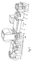
- a preferred apparatus useful for carrying out the present invention consists of six stations, arranged one after the other so that the sheets are conveyed through the respective stations in a transporting direction indicated by the arrow 10 in Fig. 1.
- the stations include a sheet supplying station 1, a double coating station 2, a sheet conveying station with high frequency dryer 3, a coating station 4, a sheet inserting station 5 and a sheet stacking station 6, which are described in further detail below.
- These stations each have separate drive mechanisms, which are controlled by a central computer 100 to synchronize the respective drive mechanisms.
- Sheet supplying station 1 has a table 11 for receiving a stack 12 of individual paper sheets.
- the sheets are preferably all of equal size and weight - 50cm by 70 cm (19.7 in by 27.6 in) and 80g/cm 2 , for example.
- a sheet lifter 13, mounted atop sheet supplying station 1, has a vacuum head 15 the suction orifice of which depends down to the uppermost sheet of stack 12. For removing the uppermost sheet from the stack 12 the suction orifice gets into contact with the rim area of that sheet which adjoints vertical outer surface 114 of the stack 12. When the head 15 rises, the outer end of the uppermost sheet is lifted.
- a stream of air is injected between the lifted portion of the uppermost sheet and the next sheet of stack 12 by a nozzle 110 mounted on the end of a flexible hose 112 which is coupled to a source of pressurized air through sheet lifter 13.
- a nozzle 110 mounted on the end of a flexible hose 112 which is coupled to a source of pressurized air through sheet lifter 13.
- Suction head 15 then is moved towards an entrance 14 of a conveyor 17 whose entrance has the form of a slot between two opposing rollers 16 and 18.
- the rollers 16, 18, extend transversely to the transport direction (arrow 10) and are in frictional contact with each other.
- One of the rollers, say lower roller 16 is driven to rotate about its axis by a not shown drive mechanism.
- Idle roller 18 follows the rotation of roller 16 and is supported in bearings such that it may yield upwardly for opening entrance 14 when a leading edge of a sheet is to be inserted.
- rollers 16, 18 When the leading edge of the lifted uppermost sheet is grasped by rollers 16, 18, it is driven through the entrance 14 along belt conveyor 17 with a speed that corresponds to the circumferencial speed of roller 16.
- Sheet lifter 13 includes a control mechanism which detects an extent of lowering the suction head 15 beyond a given value. The control mechanism then activates a lift 116 to which table 11 is coupled, to run upwardly along opposing columns 19 for raising table 11.
- a sheet supplying station 1 as described above may be obtained by MABEG Maschinenbau GmbH, Offenbach, Germany, with the machine identification no. 41988.
- the stack 12 and the related components and control may be arranged in a manner which allows an overlapping arrangement of the succeeding sheets in such a way that the leading section of each sheet overlies the trailing section of each preceding sheet.
- the overlapped sheets that emerge from the sheet supplying station 1 are supplied by belt conveyor 17 to the entrance 24 of a registering portion 20 of double coating station 2. Within this registering portion, the transport speed of the overlapped sheets is raised to approximately threefold the speed of the sheets which are delivered by the belt conveyor 17, and the overlapping of succeeding sheets is reduced.
- the registering portion 20 includes close to the entrance 24 a first pair of opposing rollers 21a, 21b, the axis of which extend parallel to those of rollers 16, 18.
- Roller 21a is arranged below the path 22 of the incoming overlapped sheets and is driven by a not shown drive mechanism controlled by the computer 100.
- Idle roller 21b is above path 22 and in frictional contact with roller 21a.
- Roller 21a is driven with the same speed as roller 16.
- Downstream of rollers 21a, 21b stop means 200 are provided in the path 22 which include a number of fingers which extend upwardly into path 22 and which are mounted on a common pivot axis below path 22. All fingers are aligned transversely to the transport direction 10.
- roller 23a being arranged below path 22 is driven approximately three times faster than roller 21a whereas idle roller 23b above path 22 frictionally contacting roller 23a follows the speed of roller 23a.
- stop means 200 When the leading edge of the first incoming sheet is escaping rollers 21a, 21b it may pass the inactivated stop means 200 and will be grasped inbetween rollers 23a, 23b. That sheet then will be accelerated corresponding to the higher speed of rollers 23a, 23b. Stop means 200 is activated timely such that the succeeding sheet will abut stop means 200. Under control of computer 100, stop means 200 is inactivated (i.e. the fingers are swung down out of path 22) at a time the overlapping of the first sheet and the succeeding sheet has reduced to approximately 1.0 to 2.0 cm (0.4 to 0.8 in).
- stop means 200 is again activated for stopping the next sheet.
- the computer 100 commands inactivating the stop means 200 at a time the overlapping of second sheet and third sheet has reduced to approximately the aforementioned extend.
- the overlapping for 1.0 to 2.0 cm of succeeding sheets is maintained by strict control of the speeds of the drive mechanisms within the following portion of double coating station 2 and stations 3 and 4.
- the stop means 200 of the registering portion 20 also serves to properly align all incoming sheets before further processing thereof.
- the accelerated overlapped sheets emerging the registering portion 20 are fed by assistance of guide rollers 28a, 28b into the coating portion 26 of double coating station 2 along the horizontally continuing path 22. Downstream of rollers 28a, 28b a first coating roller 25 is arranged above path 22 and a second roller 29 is arranged below path 22.
- the first coating roller 25 cooperates with a metering roller 27.
- a trough 210 for receiving a first liquid is formed by a portion of the circumference of the metering roller 27 adjacent a slot 212 between the metering roller 27 and the first coating roller 25, a portion of the circumference of the first coating roller 25 adjacent slot 212 and two opposing side walls 214, 216 each of which is held in cirumferencial grooves 218, 220 and 222, 224, respectively of the metering roller 27 and the first coating roller 25.
- those circumferencial grooves 218, 220, 224, 226 are spaced apart along the axis of rollers 25, 27 and provided close to the opposing end surfaces thereof.
- the width of slot 212 between metering roller 27 and first coating roller 25 may be adjusted for instance by moving metering roller 27 towards to or away from first coating roller 25. Thereby the amount of liquid which finds its way out of trough 210 through slot 212 upon the upper surface of the sheets passing underneath first coating roller 25 may be controlled.
- a sheet stripper (not shown) is abutting the periphery of the first coating roller downstream the contact thereof with the sheets to prevent a sheet from wrapping around the first coating roller 25.
- the first liquid in an embodiment of the invention, is a primer, which is an aqueous solution of an organic binding agent and a cleaved mineral pigment. Specifically, that solution is obtained by mixing approximately 5% by volume of a binding agent (available under the trademark MOVIOL from Hoechst AG, Frankfurt/Main, Germany) and approximately 5% by volume of pigment (available under the trademark AEROSIL from Degussa AG, Frankfurt/Main, Germany) with approximately 90% by volume of water.
- a binding agent available under the trademark MOVIOL from Hoechst AG, Frankfurt/Main, Germany
- AEROSIL from Degussa AG, Frankfurt/Main, Germany
- first coating roller 25 and metering roller 27 a continuous layer of primer is laid down on the web-like overlapped sheets across their width when they are passed underneath the first coating roller 25.
- trough 210 a pump 228 is provided, the outlet pipe 230 of which opens above trough 210.
- the inlet port of pump 228 is connected trough a suitable hose or pipe (not shown) to a source of the first liquid (primer).
- trough 210 is provided with an overflow line 232 which returns to said source.
- a second coating roller 29 is provided which rotates with the same speed as the first coating roller 25 which corresponds to the accelerated transport speed of the overlapped sheets.
- a tank 240 for receiving a second liquid is held below second coating roller 29.
- a baling roller 260 is provided underneath and in contact and parallel to second coating roller 29 which, when tank 240 by not shown means is filled with that second liquid, dips into that liquid (fig. 2, 7).
- second coating roller 29 and baling roller 260 are driven to rotate about their axes, liquid out of tank 240 is entrained with baling roller 260 and transferred to the periphery of second coating roller 29, which applies that liquid to the lower surface of the sheets passing between first and second coating rollers 25, 29.
- the circumferencial surface of the second coating roller 29 in the direction of the axis of that roller is for about 1.0 to 2.0 cm (0.4 to 0.8 in) shorter than the width of the sheets to be coated to prevent the liquid coated upon the upper surface of the sheets from floating over the edges of the sheets and to mix with the liquid on the second coating roller 29.
- the second coating roller 29 has to be replaced by a correspondingly shorter coating roller.
- the second liquid in an embodiment of the invention, is a low adhesion backsize, which is an aqueous solution of an organic binding agent and an adhesive rejecting agent.
- that solution may be made by mixing approximately 2% by volume of FINFIX BDA distributed by Nordmann and Rassmann, Hamburg, Germany, as binder, and approximately 10% by volume 'of TEGO-GLIDE 410 distributed by Tego-Chemie GmbH, Essen, Germany, as rejecting agent, and approximately 13% by volume of ethanol with approximately 75% by volume of water.
- aqueous primer and the aqueous low adhesion backsize are applied to the sheets simultaneously and at the same position along the path 22 by first coating roller 25 and second coating roller 29 respectively, the forces that would otherwise lead to curling or cockling of the sheets substantially counteract against each other, so that the sheets retain their smooth, even form.
- At least one, and preferably both of the coating rollers 25 and 29 are interchangeable with coating rollers of different length suitable for use with more narrow and wider sheets, respectively.
- the quantity of the aqueous solution of the primer deposited on the upper surface of the sheets may be controlled by the width of slot 212 such that approximately 2g/m 2 are deposited continuously upon the sheets.
- the aqueous solution of low adhesion backsize deposited upon the undersurface of the sheets may range approximately to 2g/m 2 continuously along the total width of the sheets.
- a photo cell positioned ahead the coating rollers 25, 29 may monitor the presence of sheets along the path 22 within coating portion 26. In case the photo cell does not detect a sheet, the output signal thereof may cause lifting of the first coating roller 25 away from second coating roller 29, or in the alternative, may cause lowering second coating roller 29 with respect to first coating roller 25 in order to prevent contact of both rollers in the absence of sheets therebetween.
- the sheet transport station 3 (Fig. 3) includes a frame 31, within which an endless vacuum belt 36 winds around rollers 33, 35, 37, 39, which are transverse to the transport direction 10. At least one of said rollers is driven under control of the computer 10 such, that the endless vacuum belt 36 advances through the sheet transport station 3 with exactly the same speed as the speed of the sheets emerging from the double coating station 2. Thereby, the overlapped condition of 1.0 to 2.0 cm is maintained during passage of the sheets through station 3 above the portion of belt 36 between rollers 35 and 37. The overlapped sheets when advancing through station 3 upon belt 36 between rollers 35 and 37 are exposed to drying means for removing moisture from the primer solution and from the low adhesion backsize solution.
- the drying means is shown as high frequency radiation source 38, which is powered by generator 30, located adjacent frame 31.
- one or more high frequency radiation sources are provided to dry the sheets.
- the frequency of the radiation emitted by the source 38 may be in the range of approximately 27 MHz.
- the radiation does not interact with the material of the sheets, but deposits its energy within the primer layer and the low adhesion backsize layer to dry those layers.
- the sheets should preferably be radiation transparent with respect to the high frequency radition, but the primer and low adhesion backsize should be radiation opaque with respect to that radiation.
- the interior of the frame may be ventilated by a continuous stream of dry air which may be introduced into the frame 31 above belt 36 and may escape from the frame through its bottom. In this way the water in the primer layer and low adhesion backsize layer is finally removed, so that the sheets are substantially dry as they exit the transport station 3 at roller 37.
- the primer and low adhesion backsize layers should be dried at rates sufficient to prevent the sheets from curling.
- the primer and low adhesion backsize are applied simultaneously, and are dried simultaneously at a uniform rate, so that the sheets do not curl or wrinkle.
- the primer and low adhesion backsize layers could be applied sequentially, or could be dried at differential rates, or both, as necessary to attenuate or prevent curling and wrinkling of the sheets.
- Coating station 4 applies a pressure sensitive adhesive to the sheets on the same surface where the primer was applied by double coating station 2, by contacting the sheets with an adhesive coated transfer belt 42.
- coating station 4 includes a table 40 upon which an endless vacuum transport belt 49 is advanced in transport direction 10. The speed of the belt 49 is controlled by computer 100 and is the same as the transport speed in station 3. Above table 40 a raised dome 41 is provided within which runs the endless transfer belt 42. Transfer belt 42 winds around roller 43a and application roller 45 and around rollers 43a, 43b, 43c, 43d, and transfer roller 44, at least one of which is driven. Transfer belt 42 may be made of, for example, silicon rubber.
- Application roller 45 preferably comprises a peripheral cylindrical surface having a plurality of cavities, or intaglio cells, for receiving pressure sensitive adhesive from a supply of such adhesive contained within tube 46.
- the adhesive may be formulated according to US patent 4,495,318 to Howard or, in the alternative, according to US patent 3,691,140 to Silver, the contents of each of which are incorporated herein.
- Application roller 45 is interchangeable with other types of application rollers, so that pressure sensitive adhesive may be applied to transfer belt 42 in different patterns, at different coating weights, and at different line speeds.
- the intaglio cells may extend completely around the periphery of application roller 45 in spaced rings for obtaining spaced and lengthwise adhesive strips 58 on sheets 56 (Fig. 6).
- Application roller 45 preferably rotates such that the peripheral surface of the application roller moves in the opposite direction of transfer belt 42, as shown in fig. 4.
- a doctor blade may also be provided between tube 46 and transfer belt 42, to doctor off excess adhesive from the application roller so that only the adhesive within the intaglio cells is applied to the transfer belt 42.
- Transfer belt 42 is entrained over rollers 43a, 43b, 43c and 43d, and the adhesive carried on the transfer belt is exposed to a first heating device 47, and subsequently to a second heating device 48.
- Heating devices 47 and 48 are preferably infrared heating devices, although other heating devices, such as high frequency heaters, are also contemplated. Also, more or less heating devices and those shown may be provided.
- first and second heating devices 47 and 48 the adhesive on transfer belt 42 is substantially dry, and can be applied to the overlapped sheets by transfer roller 44.
- One or more optional temperature feedback sensors may be positioned adjacent the heating devices, to measure the temperature of the adhesive layer and to adjust the amount of heat applied by the heating devices to dry the adhesive sufficiently.
- the adhesive is transferred from the transfer belt 42 to the overlapping sheets at an application interface between transfer roller 44 and opposed roller 44a.
- Opposed roller 44a supports the sheets against the transfer roller 44, and after the adhesive has been applied to the sheets, the coated sheets are conveyed toward sheet inserting station 5 by vacuum belt 49 for further processing.
- the pattern of adhesive disposed on the sheets depends on the pattern of adhesive applied by application roller 45 to transfer belt 42.
- application roller 45 includes a plurality of intaglio cells arranged in two bands spaced along the application roller.
- two continuous bands of adhesive are applied to the transfer belt 42, and subsequently to the overlapped sheets.
- the sheets so produced are illustrated in figure 6, wherein sheets 56 include spaced bands of adhesive 58.
- the master pads may be guillotined into individual pads of repositionable notes.
- the location, coating weight, and other characteristics of the pressure sensitive adhesive layer applied to the sheets may be changed by changing the application roller, or by altering the operating parameters such as line speed, adhesive properties, and the like.
- a sheet may be injected between coated sheets at desired intervalls.
- the injected sheets preferably are different from the coated sheets (a different color or material, for example), although they may instead be similar to the coated sheets.
- the injected sheets are uncoated, and form the bottom sheet of a master pad of repositionable notes.
- Sheet inserting station 5 contains a substantially horizontal transport floor 51 having transport belts (not shown). Frame 52 supports transport floor 51, below which is a sheet stacker 53. Sheet stacker 53 has a stack 55 of uncoated sheets that are deposited on plate 54. Further, the sheet inserting station may include a counter (not shown) that counts the sheets delivered from coating station 4. After a predetermined number of coating sheets are counted, the counter signals the sheet inserting station 5 to inject an uncoated sheet from stack 55 between the coated sheets, via a ramp rising from stack 55 to transport floor 51.
- the sheet inserting station 5 is coupled to the exit side with a sheet stacking station 6, in which the sheets received from the sheet inserting station 5 are collected and are aligned with each other.
- the aligned, coated sheets are then deposited in the form of stack 62 on plate 61.
- the stacks of sheets may then be compressed to form master pads of repositionable notes, removed, and guillotined as known in the art to form individual pads of repositionable notes.
- the above described machine may be run such that an output of approximately 4000 coated sheets per hour is obtained.
- the coating of supplied sheets of paper or similar material with pressure sensitive adhesive stripes is achieved in such a way that the sheets typically do not show any waviness, curling or other deviation from flatness.
- the method permits sheets of various sizes to be coated, limited only by the width of the transport mechanism that conveys the sheets through the apparatus. Thus, aside from the installation of suitable coating and transfer rollers, no other changes in machine parts are needed when the size of the sheets which are to coated is changed.
Abstract
Description
- The invention relates to a method for the application of a coating material such as pressure sensitive adhesive.
- It is desirable in some fields to apply pressure sensitive adhesive to a paper substrate and several methods are known for performing this process.
German patent application 36 06 199, for example, discloses a method and apparatus for applying pressure sensitive adhesive on a continous web of paper. The web is coated with a primer, or adhesion promoter and dried in a first drying station. Next, an optional low adhesion backsize, or release layer, may be coated onto the opposite surface of the web and dried at a second drying station. Finally, a circulating intermediate carrier applies the pressure sensitive adhesive, which has been partially dried while on the intermediate carrier, over the primer layer. The paper web may then be collected and further processed as desired. - The various drying steps-disclosed in the '199 patent (drying the primer layer, drying the low adhesion backsize layer, and drying the adhesive layer while on the intermediate carrier) remove moisture from the aqueous primer, backsize and adhesive materials, to prevent the paper web from curling or wrinking. However, the sequential application and drying of the primer and low adhesion backsize layers typically result in some curling of the paper web, which is undesirable. The curling problem would be more pronounced in the context of the application of a primer, low adhesion backsize, and adhesive to individual paper sheets rather than a paper web, because the web is typically in tension whereas the individual sheets are not. Thus, the method and apparatus of the '199 patent typically is not suitable for use with individual paper sheets.
- It is therefore desirable to provide a method for applying primer, low adhesion backsize, and pressure sensitive adhesive to a plurality of individual paper sheets without inducing curling or cockling of the sheets.
- An apparatus for practicing the claimed method of applying a coating material to a plurality of sheets as the sheets are conveyed past the apparatus comprises means for supplying a plurality of sheets, means for overlapping the sheets, such that a minor portion of each sheet overlies a portion of an adjacent sheet, and a minor portion of each sheet underlies a portion of a second adjacent sheet, a coating station comprising means for receiving coating material from a supply of such material, and for applying the coating material to a first major surface of the overlapping sheets as the sheets are conveyed past the coating station, and means for collecting the coated sheets. In one embodiment, the coating material is a pressure sensitive adhesive, and the sheets are sheets of paper.
- The method according to the present invention comprises the steps of providing a plurality of sheets, overlapping the sheets, such that a minor portion of each sheet overlies a portion of an adjacent sheet, and that a minor portion of each sheet underlies a portion of a second adjacent sheet, providing a source of coating material, applying a coating material to a first major surface of the overlapping sheets as the sheets are conveyed past the coating station, and collecting the coated sheets. In one embodiment of the inventive method, the coating material is a pressure sensitive adhesive, and the sheets are sheets of paper. Also provided is a sheet coated with a coating material according to the foregoing method.
- The present invention will be further explained with reference to the appended figures, wherein like structure is referred to by like numerals throughout the several views, and wherein:
- Figure 1 is a schematic perspective view of an apparatus useful for carrying out the present invention;
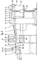
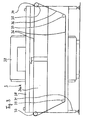
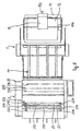
- Figures 2 to 4 are a schematic side view of stations of the apparatus of Figure 1;
- Figure 5 is a top view of the apparatus according to Fig. 2;
- Figure 6 is a perspective view of several overlapping sheets having a coating material applied thereto in accordance with the present invention; and
- Figure 7 is a schematic diagram of a detail of the apparatus.
-
- The present invention is preferably directed to the application of primer, low adhesion backsize, and pressure sensitive adhesive to a plurality of individual sheets of paper, and will be described primarily in that context. However, the present invention also has a broader applicability to the deposition of coating materials onto individual sheets of any type, and should be so understood.
- In the illustrated embodiment, a preferred apparatus useful for carrying out the present invention consists of six stations, arranged one after the other so that the sheets are conveyed through the respective stations in a transporting direction indicated by the
arrow 10 in Fig. 1. The stations include asheet supplying station 1, adouble coating station 2, a sheet conveying station withhigh frequency dryer 3, acoating station 4, asheet inserting station 5 and a sheet stacking station 6, which are described in further detail below. These stations each have separate drive mechanisms, which are controlled by acentral computer 100 to synchronize the respective drive mechanisms. -
Sheet supplying station 1 has a table 11 for receiving astack 12 of individual paper sheets. The sheets are preferably all of equal size and weight - 50cm by 70 cm (19.7 in by 27.6 in) and 80g/cm2, for example. Asheet lifter 13, mounted atopsheet supplying station 1, has avacuum head 15 the suction orifice of which depends down to the uppermost sheet ofstack 12. For removing the uppermost sheet from thestack 12 the suction orifice gets into contact with the rim area of that sheet which adjoints verticalouter surface 114 of thestack 12. When thehead 15 rises, the outer end of the uppermost sheet is lifted. A stream of air is injected between the lifted portion of the uppermost sheet and the next sheet ofstack 12 by anozzle 110 mounted on the end of aflexible hose 112 which is coupled to a source of pressurized air throughsheet lifter 13. By the injected airstream the uppermost sheet is lifted in its entirety from thestack 12 while being held at thesuction head 15 by the suction force of the vacuum.Suction head 15 then is moved towards anentrance 14 of aconveyor 17 whose entrance has the form of a slot between twoopposing rollers rollers lower roller 16, is driven to rotate about its axis by a not shown drive mechanism.Idle roller 18 follows the rotation ofroller 16 and is supported in bearings such that it may yield upwardly foropening entrance 14 when a leading edge of a sheet is to be inserted. - When the leading edge of the lifted uppermost sheet is grasped by
rollers entrance 14 alongbelt conveyor 17 with a speed that corresponds to the circumferencial speed ofroller 16. - Then the next sheet of
stack 12 is lifted and fed into theentrance 14 betweenrollers computer 100 with the drive speed of the prevouis sheet such that the leading edge of the succeeding sheet entersentrance 14 when approximately one third of the length of the previous sheet is still outsideentrance 14. Thus, all sheets ofstack 12 are conveyed byconveyor 17 one after the other in an overlapped condition according to which approximately the trailing third of the length (taken in transport direction 10) of a sheet overlaps the leading section of the succeeding sheet. When a number of sheets of thestack 12 one after the other are removed the height of thestack 12 will diminish and consequently the vacuum head will be lowered from sheet lifter to a greater extent.Sheet lifter 13 includes a control mechanism which detects an extent of lowering thesuction head 15 beyond a given value. The control mechanism then activates alift 116 to which table 11 is coupled, to run upwardly alongopposing columns 19 for raising table 11. Asheet supplying station 1 as described above may be obtained by MABEG Maschinenbau GmbH, Offenbach, Germany, with the machine identification no. 41988. - According to another embodiment of the invention the
stack 12 and the related components and control may be arranged in a manner which allows an overlapping arrangement of the succeeding sheets in such a way that the leading section of each sheet overlies the trailing section of each preceding sheet. - The overlapped sheets that emerge from the
sheet supplying station 1 are supplied bybelt conveyor 17 to theentrance 24 of a registeringportion 20 ofdouble coating station 2. Within this registering portion, the transport speed of the overlapped sheets is raised to approximately threefold the speed of the sheets which are delivered by thebelt conveyor 17, and the overlapping of succeeding sheets is reduced. - In detail, the registering
portion 20 includes close to the entrance 24 a first pair ofopposing rollers 21a, 21b, the axis of which extend parallel to those ofrollers Roller 21a is arranged below thepath 22 of the incoming overlapped sheets and is driven by a not shown drive mechanism controlled by thecomputer 100. Idle roller 21b is abovepath 22 and in frictional contact withroller 21a.Roller 21a is driven with the same speed asroller 16. Downstream ofrollers 21a, 21b stop means 200 are provided in thepath 22 which include a number of fingers which extend upwardly intopath 22 and which are mounted on a common pivot axis belowpath 22. All fingers are aligned transversely to thetransport direction 10. Upon a stop means inactivating command, all fingers may swung downwardly out ofpath 22 to allow the continuation of the run of the sheets towards another pair ofrollers path 22 for stopping further progress of an incoming sheet by abutment of the leading edge thereof against the raised fingers.Roller 23a, being arranged belowpath 22 is driven approximately three times faster thanroller 21a whereasidle roller 23b abovepath 22 frictionally contactingroller 23a follows the speed ofroller 23a. - When the leading edge of the first incoming sheet is escaping
rollers 21a, 21b it may pass the inactivated stop means 200 and will be graspedinbetween rollers rollers Stop means 200 is activated timely such that the succeeding sheet will abut stop means 200. Under control ofcomputer 100,stop means 200 is inactivated (i.e. the fingers are swung down out of path 22) at a time the overlapping of the first sheet and the succeeding sheet has reduced to approximately 1.0 to 2.0 cm (0.4 to 0.8 in). After the leading edge of the succeeding sheet (together with the trailing edge of the first sheet) has been grasped betweenrollers 23a und 23b stop means 200 is again activated for stopping the next sheet. Again, thecomputer 100 commands inactivating the stop means 200 at a time the overlapping of second sheet and third sheet has reduced to approximately the aforementioned extend. - The overlapping for 1.0 to 2.0 cm of succeeding sheets is maintained by strict control of the speeds of the drive mechanisms within the following portion of
double coating station 2 andstations portion 20 also serves to properly align all incoming sheets before further processing thereof. - The accelerated overlapped sheets emerging the registering
portion 20 are fed by assistance ofguide rollers coating portion 26 ofdouble coating station 2 along the horizontally continuingpath 22. Downstream ofrollers first coating roller 25 is arranged abovepath 22 and asecond roller 29 is arranged belowpath 22. - The
first coating roller 25 cooperates with ametering roller 27. Atrough 210 for receiving a first liquid is formed by a portion of the circumference of themetering roller 27 adjacent aslot 212 between themetering roller 27 and thefirst coating roller 25, a portion of the circumference of thefirst coating roller 25adjacent slot 212 and two opposingside walls cirumferencial grooves 218, 220 and 222, 224, respectively of themetering roller 27 and thefirst coating roller 25. As can best be seen from fig. 5, thosecircumferencial grooves rollers slot 212 betweenmetering roller 27 andfirst coating roller 25 may be adjusted for instance by movingmetering roller 27 towards to or away fromfirst coating roller 25. Thereby the amount of liquid which finds its way out oftrough 210 throughslot 212 upon the upper surface of the sheets passing underneathfirst coating roller 25 may be controlled. A sheet stripper (not shown) is abutting the periphery of the first coating roller downstream the contact thereof with the sheets to prevent a sheet from wrapping around thefirst coating roller 25. - The first liquid, in an embodiment of the invention, is a primer, which is an aqueous solution of an organic binding agent and a cleaved mineral pigment. Specifically, that solution is obtained by mixing approximately 5% by volume of a binding agent (available under the trademark MOVIOL from Hoechst AG, Frankfurt/Main, Germany) and approximately 5% by volume of pigment (available under the trademark AEROSIL from Degussa AG, Frankfurt/Main, Germany) with approximately 90% by volume of water.
- Thus, by rotating
first coating roller 25 and metering roller 27 a continuous layer of primer is laid down on the web-like overlapped sheets across their width when they are passed underneath thefirst coating roller 25. - Above trough 210 a
pump 228 is provided, theoutlet pipe 230 of which opens abovetrough 210. The inlet port ofpump 228 is connected trough a suitable hose or pipe (not shown) to a source of the first liquid (primer). Moreover,trough 210 is provided with anoverflow line 232 which returns to said source. - Below
path 22 and vertically below first coating roller 25 asecond coating roller 29 is provided which rotates with the same speed as thefirst coating roller 25 which corresponds to the accelerated transport speed of the overlapped sheets. Atank 240 for receiving a second liquid is held belowsecond coating roller 29. A balingroller 260 is provided underneath and in contact and parallel tosecond coating roller 29 which, whentank 240 by not shown means is filled with that second liquid, dips into that liquid (fig. 2, 7). Whensecond coating roller 29 and balingroller 260 are driven to rotate about their axes, liquid out oftank 240 is entrained with balingroller 260 and transferred to the periphery ofsecond coating roller 29, which applies that liquid to the lower surface of the sheets passing between first andsecond coating rollers second coating roller 29 in the direction of the axis of that roller is for about 1.0 to 2.0 cm (0.4 to 0.8 in) shorter than the width of the sheets to be coated to prevent the liquid coated upon the upper surface of the sheets from floating over the edges of the sheets and to mix with the liquid on thesecond coating roller 29. In the event the width of the sheets of another batch is smaller, thesecond coating roller 29 has to be replaced by a correspondingly shorter coating roller. By adjusting the pressure of the balingroller 260 against the second coating roller a desired thickness of the layer coated on the underside of the sheets by thesecond coating roller 29 may be obtained. A not shown sheet stripper is positioned to abut thesecond coating roller 29 downstream of the contact area of thesecond coating roller 29 with the sheets to prevent the sheets from wrapping around the second coating roller. - The second liquid, in an embodiment of the invention, is a low adhesion backsize, which is an aqueous solution of an organic binding agent and an adhesive rejecting agent. Specifically, that solution may be made by mixing approximately 2% by volume of FINFIX BDA distributed by Nordmann and Rassmann, Hamburg, Germany, as binder, and approximately 10% by volume 'of TEGO-GLIDE 410 distributed by Tego-Chemie GmbH, Essen, Germany, as rejecting agent, and approximately 13% by volume of ethanol with approximately 75% by volume of water.
- The above identified figures for percentages of ingredients may vary dependent from the characteristics of the used paper sheets.
- Because the aqueous primer and the aqueous low adhesion backsize are applied to the sheets simultaneously and at the same position along the
path 22 byfirst coating roller 25 andsecond coating roller 29 respectively, the forces that would otherwise lead to curling or cockling of the sheets substantially counteract against each other, so that the sheets retain their smooth, even form. - In a preferred embodiment, at least one, and preferably both of the
coating rollers - The quantity of the aqueous solution of the primer deposited on the upper surface of the sheets may be controlled by the width of
slot 212 such that approximately 2g/m2 are deposited continuously upon the sheets. Similarly, the aqueous solution of low adhesion backsize deposited upon the undersurface of the sheets may range approximately to 2g/m2 continuously along the total width of the sheets. - As a safety feature, a photo cell positioned ahead the
coating rollers path 22 withincoating portion 26. In case the photo cell does not detect a sheet, the output signal thereof may cause lifting of thefirst coating roller 25 away fromsecond coating roller 29, or in the alternative, may cause loweringsecond coating roller 29 with respect tofirst coating roller 25 in order to prevent contact of both rollers in the absence of sheets therebetween. - The overlapping arrangement of the sheets, and the reduced length of the low adhesion backsize roller both tend to prevent intermingling of the primer and the low adhesion backsize materials.
- The sheet transport station 3 (Fig. 3) includes a
frame 31, within which anendless vacuum belt 36 winds aroundrollers transport direction 10. At least one of said rollers is driven under control of thecomputer 10 such, that theendless vacuum belt 36 advances through thesheet transport station 3 with exactly the same speed as the speed of the sheets emerging from thedouble coating station 2. Thereby, the overlapped condition of 1.0 to 2.0 cm is maintained during passage of the sheets throughstation 3 above the portion ofbelt 36 betweenrollers station 3 uponbelt 36 betweenrollers frequency radiation source 38, which is powered bygenerator 30, locatedadjacent frame 31. In a preferred embodiment, one or more high frequency radiation sources are provided to dry the sheets. The frequency of the radiation emitted by thesource 38 may be in the range of approximately 27 MHz. Importantly, the radiation does not interact with the material of the sheets, but deposits its energy within the primer layer and the low adhesion backsize layer to dry those layers. Stated differently, the sheets should preferably be radiation transparent with respect to the high frequency radition, but the primer and low adhesion backsize should be radiation opaque with respect to that radiation. - For removing the moisture evaporated from the primer layer and the low adhesion backsize layer, the interior of the frame may be ventilated by a continuous stream of dry air which may be introduced into the
frame 31 abovebelt 36 and may escape from the frame through its bottom. In this way the water in the primer layer and low adhesion backsize layer is finally removed, so that the sheets are substantially dry as they exit thetransport station 3 atroller 37. - The primer and low adhesion backsize layers should be dried at rates sufficient to prevent the sheets from curling. In a preferred embodiment the primer and low adhesion backsize are applied simultaneously, and are dried simultaneously at a uniform rate, so that the sheets do not curl or wrinkle. However, the primer and low adhesion backsize layers could be applied sequentially, or could be dried at differential rates, or both, as necessary to attenuate or prevent curling and wrinkling of the sheets.
-
Coating station 4 applies a pressure sensitive adhesive to the sheets on the same surface where the primer was applied bydouble coating station 2, by contacting the sheets with an adhesivecoated transfer belt 42. In the illustrated embodiment,coating station 4 includes a table 40 upon which an endlessvacuum transport belt 49 is advanced intransport direction 10. The speed of thebelt 49 is controlled bycomputer 100 and is the same as the transport speed instation 3. Above table 40 a raiseddome 41 is provided within which runs theendless transfer belt 42.Transfer belt 42 winds aroundroller 43a andapplication roller 45 and aroundrollers 43a, 43b, 43c, 43d, and transferroller 44, at least one of which is driven.Transfer belt 42 may be made of, for example, silicon rubber. -
Application roller 45 preferably comprises a peripheral cylindrical surface having a plurality of cavities, or intaglio cells, for receiving pressure sensitive adhesive from a supply of such adhesive contained withintube 46. The adhesive may be formulated according to US patent 4,495,318 to Howard or, in the alternative, according to US patent 3,691,140 to Silver, the contents of each of which are incorporated herein.Application roller 45 is interchangeable with other types of application rollers, so that pressure sensitive adhesive may be applied to transferbelt 42 in different patterns, at different coating weights, and at different line speeds. In the disclosed embodiment of an apparatus useful for carrying out the invention, the intaglio cells may extend completely around the periphery ofapplication roller 45 in spaced rings for obtaining spaced and lengthwiseadhesive strips 58 on sheets 56 (Fig. 6).Application roller 45 preferably rotates such that the peripheral surface of the application roller moves in the opposite direction oftransfer belt 42, as shown in fig. 4. A doctor blade may also be provided betweentube 46 andtransfer belt 42, to doctor off excess adhesive from the application roller so that only the adhesive within the intaglio cells is applied to thetransfer belt 42. -
Transfer belt 42 is entrained overrollers 43a, 43b, 43c and 43d, and the adhesive carried on the transfer belt is exposed to afirst heating device 47, and subsequently to asecond heating device 48.Heating devices transfer belt 42 that has been coated with adhesive has passed first andsecond heating devices transfer belt 42 is substantially dry, and can be applied to the overlapped sheets bytransfer roller 44. One or more optional temperature feedback sensors (not shown) may be positioned adjacent the heating devices, to measure the temperature of the adhesive layer and to adjust the amount of heat applied by the heating devices to dry the adhesive sufficiently. - The adhesive is transferred from the
transfer belt 42 to the overlapping sheets at an application interface betweentransfer roller 44 and opposedroller 44a.Opposed roller 44a supports the sheets against thetransfer roller 44, and after the adhesive has been applied to the sheets, the coated sheets are conveyed towardsheet inserting station 5 byvacuum belt 49 for further processing. - The pattern of adhesive disposed on the sheets depends on the pattern of adhesive applied by
application roller 45 to transferbelt 42. In one embodiment,application roller 45 includes a plurality of intaglio cells arranged in two bands spaced along the application roller. Thus, two continuous bands of adhesive are applied to thetransfer belt 42, and subsequently to the overlapped sheets. The sheets so produced are illustrated in figure 6, whereinsheets 56 include spaced bands of adhesive 58. Aftersheets 56 have been stacked in the manner described below with respect to stacking station 6 to form master pads, the master pads may be guillotined into individual pads of repositionable notes. The location, coating weight, and other characteristics of the pressure sensitive adhesive layer applied to the sheets may be changed by changing the application roller, or by altering the operating parameters such as line speed, adhesive properties, and the like. - The overlapped sheets that emerge from
coating station 4 onvacuum belt 49 are conveyed tosheet inserting station 5, which draws the sheets with a slightly higher speed. Thereby, the overlapping of succeeding sheets is removed so that a leading edge of a sheet follows a trailing edge of the preceding sheet. In station 5 a sheet may be injected between coated sheets at desired intervalls. The injected sheets preferably are different from the coated sheets (a different color or material, for example), although they may instead be similar to the coated sheets. Preferably, the injected sheets are uncoated, and form the bottom sheet of a master pad of repositionable notes. -
Sheet inserting station 5 contains a substantiallyhorizontal transport floor 51 having transport belts (not shown).Frame 52 supportstransport floor 51, below which is asheet stacker 53.Sheet stacker 53 has astack 55 of uncoated sheets that are deposited onplate 54. Further, the sheet inserting station may include a counter (not shown) that counts the sheets delivered fromcoating station 4. After a predetermined number of coating sheets are counted, the counter signals thesheet inserting station 5 to inject an uncoated sheet fromstack 55 between the coated sheets, via a ramp rising fromstack 55 to transportfloor 51. - The
sheet inserting station 5 is coupled to the exit side with a sheet stacking station 6, in which the sheets received from thesheet inserting station 5 are collected and are aligned with each other. The aligned, coated sheets are then deposited in the form ofstack 62 onplate 61. The stacks of sheets may then be compressed to form master pads of repositionable notes, removed, and guillotined as known in the art to form individual pads of repositionable notes. Depending on the adhesive formulation coated onto the sheets, it may be desirable to allow the coated sheets to age (12 hours, for example) prior to guillotining, to allow the adhesion strength to increase as the adhesive dries more completely. - The above described machine may be run such that an output of approximately 4000 coated sheets per hour is obtained.
- The advantages of the method are numerous. For example, the coating of supplied sheets of paper or similar material with pressure sensitive adhesive stripes is achieved in such a way that the sheets typically do not show any waviness, curling or other deviation from flatness. Also, the method permits sheets of various sizes to be coated, limited only by the width of the transport mechanism that conveys the sheets through the apparatus. Thus, aside from the installation of suitable coating and transfer rollers, no other changes in machine parts are needed when the size of the sheets which are to coated is changed.
- Other benefits include the ability to provide sheets having different printed messages, different cutters, different materials (recyled or virgin paper, for example), or different textures, for example, within a single batch or stack of sheets. For example, a calender (having different printed information on each sheet) could be easily produced by the method of the present invention if the stack of sheets were organized in the proper order. Another advantage is that the coating materials used with the present invention are preferably water based, and thus potentially harmful organic solvents may be eliminated from the coating process.
- The present invention has now been described with reference to several embodiments thereof. The scope of the present invention should not be limited to the structures described herein, but rather by the language of the claims.
Claims (10)
- A method of applying a coating material to a plurality of sheets, comprising the steps of:(a) providing a plurality of sheets;(b) overlapping the sheets, such that at least a minor portion of each sheet overlies a minor portion of an adjacent sheet, and at least a minor portion of each sheet underlies a minor portion of a second adjacent sheet;(c) providing a source of coating material;(d) disposing the coating material on a transfer surface;(e) applying the coating material to a first major surface of the overlapping sheets by contacting the sheets with the transfer surface to apply the coating material to the sheets as the sheets are conveyed past the transfer surface; and(f) collecting the coated sheets.
- The method of claim 1, wherein the coating material is a pressure sensitive adhesive.
- The method of claim 2, wherein the coating material is a water-based pressure sensitive adhesive.
- The method of claim 1, wherein the sheets are paper.
- The method of claim 1, wherein step (d) further comprises at least partially drying the coating material while the coating material is disposed on the transfer surface.
- The method of claim 1, wherein the method further comprises a step (d') of coating a primer on the first major surface of the sheets, and coating a low adhesion backsize on the second major surface of the sheets, step (d') occuring before step (d).
- The method of claim 6, wherein the primer coating and the low adhesion backsize coating are applied simultaneously.
- The method of claim 6, wherein step (d') further includes drying the primer and the low adhesion backsize onto the sheets.
- The method of claim 8, wherein the primer and low adhesion backsize coatings are dried at a rate sufficient to prevent curling and wrinkling of the sheets.
- The method of claim 8, wherein the primer and the low adhesion backsize are dried by high frequency radiation.
Applications Claiming Priority (3)
| Application Number | Priority Date | Filing Date | Title |
|---|---|---|---|
| DE4305081A DE4305081C2 (en) | 1993-02-19 | 1993-02-19 | Method and device for applying pressure sensitive adhesive to sheets of paper or the like material |
| DE4305081 | 1993-02-19 | ||
| EP94908304A EP0684974B1 (en) | 1993-02-19 | 1994-02-15 | Apparatus for applying a coating material to sheets |
Related Parent Applications (2)
| Application Number | Title | Priority Date | Filing Date |
|---|---|---|---|
| EP94908304A Division EP0684974B1 (en) | 1993-02-19 | 1994-02-15 | Apparatus for applying a coating material to sheets |
| EP94908304.2 Division | 1994-09-01 |
Publications (3)
| Publication Number | Publication Date |
|---|---|
| EP0802250A2 EP0802250A2 (en) | 1997-10-22 |
| EP0802250A3 EP0802250A3 (en) | 1998-05-13 |
| EP0802250B1 true EP0802250B1 (en) | 2003-07-09 |
Family
ID=6480835
Family Applications (2)
| Application Number | Title | Priority Date | Filing Date |
|---|---|---|---|
| EP97109568A Expired - Lifetime EP0802250B1 (en) | 1993-02-19 | 1994-02-15 | Method for applying a coating material to sheets |
| EP94908304A Expired - Lifetime EP0684974B1 (en) | 1993-02-19 | 1994-02-15 | Apparatus for applying a coating material to sheets |
Family Applications After (1)
| Application Number | Title | Priority Date | Filing Date |
|---|---|---|---|
| EP94908304A Expired - Lifetime EP0684974B1 (en) | 1993-02-19 | 1994-02-15 | Apparatus for applying a coating material to sheets |
Country Status (10)
| Country | Link |
|---|---|
| US (3) | US5487780A (en) |
| EP (2) | EP0802250B1 (en) |
| JP (1) | JP2846474B2 (en) |
| AT (2) | ATE244744T1 (en) |
| AU (2) | AU677639B2 (en) |
| DE (3) | DE4305081C2 (en) |
| DK (1) | DK0684974T3 (en) |
| ES (1) | ES2114178T3 (en) |
| TW (1) | TW218361B (en) |
| WO (1) | WO1994019419A1 (en) |
Families Citing this family (34)
| Publication number | Priority date | Publication date | Assignee | Title |
|---|---|---|---|---|
| DE4305081C2 (en) * | 1993-02-19 | 1996-08-01 | Minnesota Mining & Mfg | Method and device for applying pressure sensitive adhesive to sheets of paper or the like material |
| EP1234682B1 (en) * | 1994-08-17 | 2006-02-22 | Minnesota Mining And Manufacturing Company | Method and apparatus for applying a coating material to sheets |
| US5849358A (en) * | 1994-08-17 | 1998-12-15 | Minnesota Mining And Manufacturing Company | Apparatus and method for applying coating materials to individual sheet members |
| US6180172B1 (en) * | 1994-11-29 | 2001-01-30 | Henkel Kommanditgesellschaft Auf Aktien | Process and apparatus for treating surfaces |
| ATE183692T1 (en) * | 1995-10-04 | 1999-09-15 | Johannes A Ritter | NOTEPAD |
| CA2233953A1 (en) * | 1995-10-17 | 1997-04-24 | Minnesota Mining And Manufacturing Company | Water-based microsphere adhesives |
| DE19544637A1 (en) * | 1995-11-30 | 1997-06-05 | Johannes A Ritter | Method and device for applying pressure sensitive adhesive |
| DE19544636A1 (en) * | 1995-11-30 | 1997-06-05 | Johannes A Ritter | Transfer web for applying pressure sensitive adhesives and process for their production |
| JP2000505350A (en) * | 1996-02-16 | 2000-05-09 | ミネソタ マイニング アンド マニュファクチャリング カンパニー | Apparatus and method for applying coating material to individual sheet members |
| DE19704450C2 (en) * | 1997-02-06 | 1999-07-08 | Ritter & Co | Method and device for producing printed sticky notes |
| US6406244B1 (en) | 1998-07-09 | 2002-06-18 | Frederic P. A. Le Riche | Stack of sheets with repositionable adhesive alternating between opposite edges and containing one or more sheets different from other sheets |
| DE19903905B4 (en) * | 1999-02-01 | 2008-04-10 | Amc Pancke Ag Allied Methods Of Communication | Process and device for the production of adhesive labels |
| DE19937467A1 (en) * | 1999-08-07 | 2001-02-08 | Roland Man Druckmasch | Device for tempering coating media |
| DE10037028A1 (en) * | 2000-07-28 | 2002-02-07 | Winkler & Duennebier Ag | Sticky-edge paper sheet producing process involves stacking the paper sheets, applying anti-stick coating to one side, separating them, re stacking and coating |
| KR200231988Y1 (en) * | 2001-02-27 | 2001-07-03 | 신일산업 주식회사 | auto roll laminater |
| US7056411B2 (en) * | 2001-11-05 | 2006-06-06 | The Procter & Gamble Company | Variable stretch composites and methods of making the composite |
| MXPA04004110A (en) * | 2001-11-05 | 2004-07-23 | Procter & Gamble | Stretch composites and methods of making the composite. |
| EP1607334B1 (en) * | 2002-03-28 | 2007-08-29 | DEUTSCHE SISI-WERKE GmbH & Co. Betriebs KG | Method and device for bonding drinking straws onto plastic bags |
| GB2388813B (en) * | 2002-05-21 | 2004-11-10 | Sustainable Trading Ltd | Pads of paper |
| US20040181200A1 (en) * | 2002-11-05 | 2004-09-16 | Desai Fred Naval | Variable stretch composites and methods of making the composite |
| US20040222553A1 (en) * | 2003-05-05 | 2004-11-11 | The Procter & Gamble Company | Method for making a stretch composite |
| US7160413B2 (en) * | 2004-01-09 | 2007-01-09 | Mipox International Corporation | Layered support and method for laminating CMP pads |
| EP1861209A1 (en) * | 2005-03-11 | 2007-12-05 | Ryco Book Protection Services Limited | Method and apparatus for indirectly coating a substrate with a hot flowable viscous adhesive |
| WO2009089586A1 (en) * | 2008-01-17 | 2009-07-23 | Ra Corporation Pty Ltd | Notepad forming method and apparatus therefor |
| DE102010045116B4 (en) * | 2010-09-13 | 2013-10-17 | Harrexco Ag | Processing station with a coating device, method for applying a liquid and use |
| FI20115763A0 (en) * | 2011-07-20 | 2011-07-20 | Upm Raflatac Oy | Label laminates as well as the procedure and system for manufacturing a label laminate |
| FI20115765A0 (en) * | 2011-07-20 | 2011-07-20 | Upm Raflatac Oy | A label laminate and a method and system for producing a label laminate |
| EP2786848B1 (en) * | 2013-04-02 | 2016-05-18 | Airbus Operations GmbH | A fibre fabric cutting system |
| CN109807019A (en) * | 2017-11-21 | 2019-05-28 | 中国科学院金属研究所 | A kind of device and its application method for ceramic fractional distillation filling-material combination bonding |
| WO2020233849A1 (en) * | 2019-05-20 | 2020-11-26 | Voith Patent Gmbh | Applicator unit and application method |
| DE102020106095A1 (en) * | 2020-03-06 | 2021-09-09 | Voith Patent Gmbh | Process for coating a fibrous web |
| CN111974608A (en) * | 2020-08-05 | 2020-11-24 | 蒙城县弘文信息科技有限公司 | Rubber coating device is used in heated board processing |
| KR102260469B1 (en) * | 2020-10-28 | 2021-06-02 | 이동욱 | Painting and drying apparatus |
| CN112676112B (en) * | 2020-12-15 | 2022-02-18 | 宁波华昱化学材料有限公司 | Coating brushing device |
Family Cites Families (163)
| Publication number | Priority date | Publication date | Assignee | Title |
|---|---|---|---|---|
| DE7610712U1 (en) | 1900-01-01 | Druck Und Papier Verarbeitungs Gmbh, 5000 Koeln | ||
| US1781877A (en) | 1927-03-22 | 1930-11-18 | Patent & Licensing Corp | Method of and mechanism for coating roofing elements |
| DE590293C (en) * | 1931-05-19 | 1935-03-22 | Arthur Nicolaus | Process for the production of non-rolling, gummed papers, e.g. B. for postage stamps |
| US2060800A (en) | 1935-12-06 | 1936-11-17 | Ehrig Hans | Sheet feeder |
| US2130605A (en) * | 1936-06-08 | 1938-09-20 | Edwin G Staude | Method of gumming and drying adhesive on flat surfaces |
| US2146945A (en) | 1936-07-31 | 1939-02-14 | Ehrig Hans | Sheet feeder |
| DE976092C (en) * | 1941-07-24 | 1963-02-21 | Champion Paper Co Ltd | Process for the production of coated paper dried on a glass surface |
| US2503984A (en) * | 1948-05-07 | 1950-04-11 | Wolff Book Mfg Co Inc H | Machine for pasting the edges of sheets to each other |
| US2647463A (en) * | 1949-05-10 | 1953-08-04 | Ferrar Bernard | Slip sheeter attachment for duplicators |
| CA677797A (en) * | 1955-11-18 | 1964-01-14 | Minnesota Mining And Manufacturing Company | Sheet material having a pressure-sensitive adhesive coating of acrylate ester copolymer |
| US3029731A (en) * | 1959-03-25 | 1962-04-17 | Zeuthen & Aagaard As | Mechanism for duplicators for inserting interleaving sheets between the printed sheets |
| US3121021A (en) * | 1960-04-18 | 1964-02-11 | Minnesota Mining & Mfg | Breathable surgical adhesive tapes |
| US3265556A (en) * | 1961-10-20 | 1966-08-09 | Butler Manufacturing Co | Fiber reinforced plastic panel and method of making same |
| US3257226A (en) * | 1962-11-08 | 1966-06-21 | Exxon Research Engineering Co | Wax coating method and apparatus |
| DE1594309A1 (en) * | 1963-07-20 | 1969-09-11 | Vorwerk & Sohn | Process for the production of air-permeable self-adhesive tapes or films, in particular plasters |
| US3360396A (en) * | 1964-05-25 | 1967-12-26 | Diamond Alkali Co | Polyvinyl fluoride coating |
| US3426754A (en) * | 1964-06-12 | 1969-02-11 | Celanese Corp | Breathable medical dressing |
| US3407084A (en) * | 1964-10-01 | 1968-10-22 | Us Envelope Co | Coating method and apparatus |
| NL136831C (en) * | 1965-08-20 | 1900-01-01 | ||
| DE1594060A1 (en) * | 1966-01-08 | 1970-07-09 | Wilh Jackstaedt & Co | Flat adhesive material provided with a self-adhesive layer |
| US3655488A (en) | 1967-07-17 | 1972-04-11 | Bondit Corp | Apparatus for joining sheet material |
| US3467060A (en) * | 1967-10-19 | 1969-09-16 | Longacre Press Inc The | Apparatus for coating and curing epoxy resin on sheets |
| SE348777B (en) | 1968-02-08 | 1972-09-11 | Ethyl Corp | |
| US3565728A (en) * | 1968-05-09 | 1971-02-23 | Pak Well Corp | Method and apparatus for forming a continuous assembly of articles in overlapping and interconnected form |
| DE1752337A1 (en) * | 1968-05-10 | 1971-05-19 | Erich Pagendarm | Plant for the coating of diffusion-friendly adhesives and dyes and the like. |
| NO134790C (en) * | 1968-07-09 | 1984-03-22 | Smith & Nephew | Kleber ,; PRESSURE SENSITIVE, WATERPUME-PERMEABLE PRODUCT FOR SKIN USE BY HUMANS. |
| US3590452A (en) | 1969-01-09 | 1971-07-06 | Dayco Corp | Roller applicator device |
| US3607579A (en) * | 1969-07-14 | 1971-09-21 | Xerox Corp | Labeling apparatus for multisheet labels |
| US3802952A (en) | 1969-07-18 | 1974-04-09 | E Gurin | Biaxally stress-oriented plastic sheet laminated with nbr adhesive to rubber-coated paper |
| US3676184A (en) | 1969-08-22 | 1972-07-11 | Combined Paper Mills Inc | Method for controlling varying liquid penetration of a continuous paper web |
| BE754981A (en) * | 1969-08-22 | 1971-02-01 | Combined Paper Mills Inc | METHOD AND APPARATUS FOR PROCESSING PAPER |
| US3677788A (en) * | 1970-02-03 | 1972-07-18 | Johnson & Johnson | Adhesive tape |
| US3691140A (en) * | 1970-03-09 | 1972-09-12 | Spencer Ferguson Silver | Acrylate copolymer microspheres |
| US3722878A (en) | 1970-10-01 | 1973-03-27 | Oppenweiler Binder & Co Maschb | Sheet feeder |
| US3702482A (en) | 1970-12-23 | 1972-11-07 | Xerox Corp | Bias roll transfer |
| GB1422396A (en) | 1973-01-26 | 1976-01-28 | Ciba Geigy Ag | Film adhesives |
| JPS5518801B2 (en) * | 1973-02-23 | 1980-05-21 | ||
| JPS5226211B2 (en) * | 1973-02-28 | 1977-07-13 | ||
| US3857731A (en) | 1973-04-06 | 1974-12-31 | Minnesota Mining & Mfg | Acrylate microsphere-surfaced sheet material |
| US4054710A (en) * | 1973-07-16 | 1977-10-18 | Johns-Manville Corporation | Laminated insulation blanket |
| US3934066A (en) * | 1973-07-18 | 1976-01-20 | W. R. Grace & Co. | Fire-resistant intumescent laminates |
| US3897780A (en) * | 1973-07-30 | 1975-08-05 | Robert E Trousil | Colostomy appliance adhesive patch for fastening same to the body |
| JPS5079534A (en) * | 1973-11-17 | 1975-06-28 | ||
| US3861351A (en) * | 1973-12-06 | 1975-01-21 | Dusenbery Co John | Apparatus for coating and stacking printed sheets |
| DE2425130B2 (en) | 1974-05-24 | 1976-04-08 | Fischer & Krecke, 4800 Bielefeld | DEVICE FOR THE PROTECTION OF FORCED ROLLERS AND ROLLERS THAT ROLLER ON TOP OF EACH OTHER AT DIFFERENT CIRCULAR SPEEDS |
| AR206823A1 (en) | 1974-11-02 | 1976-08-23 | Heidelberger Druckmasch Ag | TRANSLATION DRUM ON ROTARY SHEET PRINTER MACHINES |
| US3956552A (en) | 1975-05-05 | 1976-05-11 | Champion Products Inc. | Flocked heat transfer method, apparatus and article |
| GB1563695A (en) * | 1975-07-29 | 1980-03-26 | Smith & Nephew Res | Adhesive material |
| US4165404A (en) * | 1975-09-26 | 1979-08-21 | E. I. Du Pont De Nemours And Company | Process for producing laminates of fabric and fluorocarbon copolymer |
| US4024679A (en) * | 1976-01-05 | 1977-05-24 | Irvin Industries, Inc. | Air supported structure membrane configuration |
| JPS52123437A (en) * | 1976-04-09 | 1977-10-17 | Kuraray Co Ltd | Material for protecting surface |
| CA1087712A (en) | 1976-11-01 | 1980-10-14 | Northern Telecom Limited | Control for wire coating line |
| US4166152B1 (en) | 1977-08-17 | 1999-05-18 | Minnesota Mining & Mfg | Tacky polymeric microspheres |
| DE2743828B1 (en) | 1977-09-29 | 1979-02-22 | Voith Gmbh J M | Method and device for coating one side and for moistening the other side of a fiber web |
| CH623288A5 (en) | 1977-10-24 | 1981-05-29 | Ferag Ag | |
| US4112177A (en) * | 1978-01-23 | 1978-09-05 | Minnesota Mining And Manufacturing Company | Porous adhesive tape |
| US4202925A (en) * | 1978-04-04 | 1980-05-13 | Johnson & Johnson | Paper surgical tape |
| US4193178A (en) | 1978-05-18 | 1980-03-18 | Persista, Inc. | Coating roller |
| GB2034203A (en) | 1978-11-22 | 1980-06-04 | Tba Industrial Products Ltd | Applicator Bar |
| US4219376A (en) * | 1979-03-05 | 1980-08-26 | L. E. Carpenter & Company, Inc. | Flexible acoustical wall covering, method of making same, and wall panel employing same |
| JPS6049235B2 (en) * | 1979-08-18 | 1985-10-31 | 日東電工株式会社 | pressure sensitive adhesive tape |
| FR2465320A1 (en) * | 1979-09-14 | 1981-03-20 | Thomson Csf | PIEZOELECTRIC COMPOSITE MATERIAL FILM AND METHOD FOR MANUFACTURING THE SAME |
| DE2951802A1 (en) | 1979-12-21 | 1981-07-09 | Agfa-Gevaert Ag, 5090 Leverkusen | DEVICE AND METHOD FOR FULLY AUTOMATIC LACQUERING OF BAND-SHAPED MATERIALS |
| US4263869A (en) * | 1980-01-14 | 1981-04-28 | Paul Wahnschaff | Glue applicator |
| JPS5712084A (en) * | 1980-06-27 | 1982-01-21 | Dainippon Ink & Chem Inc | Pressure-sensitive adhesive sheet |
| JPS5778471A (en) * | 1980-10-31 | 1982-05-17 | Nitto Electric Ind Co Ltd | Pressure-sensitive double-side adherent tape |
| CH649267A5 (en) * | 1980-11-17 | 1985-05-15 | Ferag Ag | METHOD AND DEVICE FOR INSERTING AT LEAST ONE INSERT IN PRINTED PRODUCTS. |
| CH648772A5 (en) | 1980-12-11 | 1985-04-15 | Steinemann Ulrich Ag | MACHINE FOR ONE-SIDED COATING THIN BOW, ESPECIALLY PAPER BOW. |
| JPS57115479A (en) * | 1981-01-09 | 1982-07-17 | Nitto Electric Ind Co Ltd | Preparation of pressure-sensitive double-coated adhesive tape |
| US4781306A (en) | 1981-02-19 | 1988-11-01 | Minnesota Mining And Manufacturing Company | Stack of sheet material |
| US4416392A (en) | 1981-02-19 | 1983-11-22 | Minnesota Mining & Manufacturing Company | Dispenser for adhesive coated sheet material |
| US4384544A (en) | 1981-04-03 | 1983-05-24 | Weishew Joseph F | Liquid application system |
| DE3114581C2 (en) | 1981-04-10 | 1984-01-19 | M.A.N.- Roland Druckmaschinen AG, 6050 Offenbach | Conveyor device for a sheet-fed rotary printing press |
| US4427737A (en) * | 1981-04-23 | 1984-01-24 | E. R. Squibb & Sons, Inc. | Microporous adhesive tape |
| DE3117855C2 (en) | 1981-05-06 | 1984-09-06 | M.A.N.- Roland Druckmaschinen AG, 6050 Offenbach | Coating unit in the delivery of a sheet-fed rotary printing press |
| DE3121992A1 (en) | 1981-06-03 | 1982-12-23 | D.I.S. Versand Service GmbH, 4830 Gütersloh | Sheet web printed with advertising, method for producing a printed advertising means from the printed sheet web and device for implementing the method |
| CH652105A5 (en) | 1981-07-15 | 1985-10-31 | Grapha Holding Ag | METHOD AND DEVICE FOR STORING PRINTED SHEETS. |
| JPS5813682A (en) * | 1981-07-16 | 1983-01-26 | Nippon Carbide Ind Co Ltd | Pressure-sensitive adhesive layer |
| JPS5853975A (en) * | 1981-09-28 | 1983-03-30 | Nitto Electric Ind Co Ltd | Production of pressure-sensitive adhesive tape |
| US4442162A (en) * | 1981-10-09 | 1984-04-10 | Brunswick Corporation | Chemical and biological resistant material and method of fabricating same |
| JPS5896670A (en) * | 1981-12-02 | 1983-06-08 | Nitto Electric Ind Co Ltd | Preparation of pressure-sensitive adhesive tape |
| JPS58167667A (en) * | 1982-03-27 | 1983-10-03 | Nitto Electric Ind Co Ltd | Preparation of pressure-sensitive adhesive tape |
| JPS58174484A (en) * | 1982-04-08 | 1983-10-13 | Kao Corp | Pressure-sensitive adhesive tape or sheet |
| DE3219094A1 (en) * | 1982-05-21 | 1983-11-24 | Reck, Bernd, 5450 Neuwied | Method and apparatus for partially reducing the adhesive effect on double-sided adhesive tapes, and on printing blocks, offset printing blankets and other articles to be fixed by these adhesive tapes, and also on the joining surfaces intended for fixing |
| JPH0246626B2 (en) * | 1982-06-16 | 1990-10-16 | Daio Kakoshi Kogyo Kk | GOSEIJUSHIITAYOHYOMENHOGOZAI |
| DE3248232C1 (en) | 1982-12-27 | 1984-02-09 | M.A.N.- Roland Druckmaschinen AG, 6050 Offenbach | Printing machine for printing and final varnishing of sheets |
| JPS59176376A (en) * | 1983-03-28 | 1984-10-05 | Nitto Electric Ind Co Ltd | Pressure-sensitive adhesive sheet or tape |
| GB8309993D0 (en) * | 1983-04-13 | 1983-05-18 | Smith & Nephew Ass | Surgical adhesive dressing |
| JPS6026077A (en) * | 1983-07-21 | 1985-02-08 | Nippon Hikari Fiber Kk | Self-adhesive tape |
| US4612074A (en) * | 1983-08-24 | 1986-09-16 | American Biltrite Inc. | Method for manufacturing a printed and embossed floor covering |
| US4558888A (en) * | 1983-09-19 | 1985-12-17 | Minnesota Mining And Manufacturing Company | Strip of binding tape |
| JPS60143866A (en) | 1983-12-29 | 1985-07-30 | Konishiroku Photo Ind Co Ltd | Process and device for coating |
| US4495318A (en) * | 1984-03-21 | 1985-01-22 | International Cube Corporation | Low tack microsphere glue |
| ZA853021B (en) | 1984-04-30 | 1985-12-24 | Banson Pty Ltd | Pads and their formation |
| DE3417746A1 (en) * | 1984-05-12 | 1985-11-14 | Jackstädt GmbH, 5600 Wuppertal | Self-adhesive layer with covering arranged on the side facing away from its carrier |
| US4536012A (en) | 1984-05-15 | 1985-08-20 | H. B. Fuller Company | Book binding process |
| JPS60248786A (en) * | 1984-05-22 | 1985-12-09 | Nitto Electric Ind Co Ltd | Production of pressure-sensitive adhesive tape |
| US4566014A (en) | 1984-05-31 | 1986-01-21 | The Mead Corporation | Drop counter printer control system |
| JPS6110A (en) * | 1984-06-08 | 1986-01-06 | Sekisui Chem Co Ltd | Preparation of poultice |
| FR2568146B1 (en) | 1984-07-24 | 1987-05-07 | Boechat Roland | MACHINE FOR VARNISHING BOTH SIDES OF CARDBOARD SHEETS |
| US4598112A (en) | 1984-09-14 | 1986-07-01 | International Cube Corp. | Low tack cationic microsphere glue |
| GB2166717A (en) | 1984-11-13 | 1986-05-14 | Rodwell Htb Limited | Feeding stream of sheets to treatment station |
| US4681035A (en) | 1985-03-14 | 1987-07-21 | M.A.N.-Roland Druckmaschinen Aktiengesellschaft | Rotary offset printing machine system |
| US4698110A (en) * | 1985-11-27 | 1987-10-06 | E. I. Du Pont De Nemours And Company | Preparation of fluoropolymer coated material |
| US4822670A (en) | 1985-12-18 | 1989-04-18 | Nichiban Company Limited | Removable adhesive sheet or tape |
| GB8602510D0 (en) * | 1986-02-01 | 1986-03-05 | Waddingtons Ltd | Coating of web materials |
| DE3632816A1 (en) * | 1986-09-26 | 1988-03-31 | Erich Pagendarm | Substrate surface-coated with an adhesive composition |
| DE3628784A1 (en) * | 1986-08-25 | 1988-03-03 | Erich Pagendarm | Process for applying a contact adhesive comprising a liquid-containing composition to a substrate |
| DE3606199C2 (en) * | 1986-02-26 | 1996-06-13 | Print Inform Gmbh & Co Kg | Process for applying a pressure-sensitive adhesive from a liquid-containing mass to a substrate and substrate with an easily removable and reusable adhesive layer |
| US4967740A (en) * | 1986-06-11 | 1990-11-06 | Minnesota Mining And Manufacturing Company | Dispensable tapes |
| DE3633106A1 (en) * | 1986-09-30 | 1988-03-31 | Pagendarm Beschichtungstechnik | METHOD AND DEVICE FOR COATING A MOVING SUPPORT MATERIAL WITH A COATING AGENT CONTAINING A SOLVENT |
| DE3637452A1 (en) * | 1986-11-04 | 1988-05-19 | Pagendarm Beschichtungstechnik | FLOW CONTROL DEVICE |
| DE3639487A1 (en) * | 1986-11-18 | 1988-05-19 | Pagendarm Beschichtungstechnik | METHOD AND DEVICE FOR APPLYING A COATING AGENT TO A SUBSTRATE |
| US4779557A (en) | 1986-12-04 | 1988-10-25 | Joseph Frazzitta | Coater for a sheet fed printing press |
| US4961964A (en) | 1987-06-26 | 1990-10-09 | Epic Products International Corp. | Method for coating a web with wet ink thereon |
| DE3722346A1 (en) * | 1987-07-07 | 1989-01-26 | Pagendarm Beschichtungstechnik | METHOD AND DEVICE FOR RELAXING A THERMOPLASTIC FILM COATING |
| DE3722345A1 (en) * | 1987-07-07 | 1989-01-26 | Pagendarm Beschichtungstechnik | DEVICE FOR PULLING IN THE BEGINNING OF A MATERIAL RAIL IN A TREATMENT PLANT |
| DE3741680A1 (en) * | 1987-12-09 | 1989-06-22 | Pagendarm Gmbh | Method and device for glazing the surface of a paper web |
| DE3802797A1 (en) | 1988-01-30 | 1989-08-10 | Guenther Dr Schwarz | METHOD AND DEVICE FOR PRODUCING FAST-HARDENING COVERINGS ON CARRIER BOLTS |
| US4973040B1 (en) | 1988-02-05 | 1995-09-12 | Norman H Kemp | Paper guide wheel |
| US5029832A (en) * | 1989-04-14 | 1991-07-09 | Bell & Howell Phillipsburg Co. | In-line rotary inserter |
| US5045569A (en) | 1988-11-30 | 1991-09-03 | Minnesota Mining And Manufacturing Company | Hollow acrylate polymer microspheres |
| US5009408A (en) * | 1989-03-16 | 1991-04-23 | Pulskamp Nicholas R | Continuous feed board inserter |
| US4903600A (en) | 1989-04-24 | 1990-02-27 | Long John A | Product collator imbricator and printer |
| US5032460A (en) | 1989-08-14 | 1991-07-16 | Minnesota Mining And Manufacturing Company | Method of making vinyl-silicone copolymers using mercapto functional silicone chain-transfer agents and release coatings made therewith |
| US5202190A (en) | 1989-08-14 | 1993-04-13 | Minnesota Mining And Manufacturing Company | Method of making vinyl-silicone copolymers using mercapto functional silicone chain-transfer agents and release coatings made therewith |
| US5143250A (en) | 1989-11-14 | 1992-09-01 | The Bates Manufacturing Company | Desk caddy for refillably dispensing self-sticking fanfolded notepaper featuring vertically moveable platform on tracking means |
| DE69029846T2 (en) | 1990-01-22 | 1997-07-10 | Minnesota Mining & Mfg | Aqueous, repositionable, pressure-sensitive adhesives with high adhesion |
| US5067699A (en) * | 1990-02-07 | 1991-11-26 | Am International Incorporated | Sheet material handling apparatus with inserter assembly |
| US5080254A (en) | 1990-02-09 | 1992-01-14 | Rubbermaid Incorporated | Adhesive note pad paper dispenser |
| AU631966B2 (en) | 1990-02-16 | 1992-12-10 | International Partners In Glass Research | Method and apparatus for coating articles |
| WO1991013690A1 (en) | 1990-03-16 | 1991-09-19 | Vermehren, H., Richard | Gummer roll apparatus |
| DE4009797A1 (en) | 1990-03-27 | 1991-10-02 | Pagendarm Gmbh | METHOD AND ARRANGEMENT FOR CONDENSING VAPOROUS SUBSTANCES |
| US4973513A (en) * | 1990-04-04 | 1990-11-27 | Minnesota Mining And Manufacturing Company | Process for applying a release coating to a wet nonwoven backing and article |
| DE4012176C2 (en) | 1990-04-14 | 2000-08-17 | Pagendarm Technologie Gmbh | Device for treating a coated substrate web |
| SE9001492L (en) | 1990-04-25 | 1991-10-26 | Ekonomitryck Ab | FORM AND PROCEDURE |
| DE4013319A1 (en) * | 1990-04-26 | 1991-10-31 | Pagendarm Gmbh | DEVICE FOR APPLYING A LAYER TO A SUBSTRATE |
| DE4013776A1 (en) * | 1990-04-28 | 1991-10-31 | Pagendarm Gmbh | Device for coating substrate - has coating material pre-formed from at least two constituents applied as layers on material carrier |
| JPH0414434A (en) * | 1990-05-07 | 1992-01-20 | Toppan Printing Co Ltd | Lamination |
| US5050909A (en) | 1990-06-01 | 1991-09-24 | Minnesota Mining And Manufacturing Company | Stack of sheet assemblies |
| US5040778A (en) | 1990-07-16 | 1991-08-20 | Ark, Inc. | Apparatus for automatically inverting workpieces of limp sheet material |
| DE4023442A1 (en) | 1990-07-24 | 1992-01-30 | Pagendarm Gmbh | METHOD AND DEVICE FOR DRYING A COATED SUBSTRATE RAIL |
| US5085167A (en) * | 1990-07-27 | 1992-02-04 | Pagendarm Gmbh | Apparatus for applying coating material to a substrate |
| IT1242578B (en) | 1990-10-02 | 1994-05-16 | Gd Spa | DEVICE FOR THE APPLICATION OF ADHESIVE SUBSTANCE TO SHEET MATERIAL |
| DE4035091A1 (en) * | 1990-11-05 | 1992-05-07 | Pagendarm Gmbh | APPLICATION DEVICE |
| IE920324A1 (en) | 1991-02-12 | 1992-08-12 | Robert G Cornell | Paper article dispenser |
| US5378281A (en) | 1991-09-13 | 1995-01-03 | Kamata; Yoshiyuki | Pretreating apparatus for adhesion of plastic sheet materials |
| US5167346A (en) | 1992-03-20 | 1992-12-01 | Minnesota Mining And Manufacturing Company | Dispenser for a stack of sheets |
| DE4211638C2 (en) | 1992-04-07 | 1995-06-29 | Roland Man Druckmasch | Process and device for painting and for printing sheets in a coating unit with a printing unit |
| JPH05289138A (en) * | 1992-04-10 | 1993-11-05 | Nippon Telegr & Teleph Corp <Ntt> | Light phase synchronizing circuit and light phase synchronous receiver |
| US5421259A (en) | 1992-09-24 | 1995-06-06 | Kabushiki Kaisha Tokyo Kikai Seisakusho | Guide roller for printing press |
| US5618062A (en) | 1992-11-09 | 1997-04-08 | Minnesota Mining And Manufacturing Company | Note or note pad preparation method |
| US5382055A (en) | 1992-11-09 | 1995-01-17 | Minnesota Mining And Manufacturing Company | Note or note pad preparation method |
| DE4302129C2 (en) | 1993-01-27 | 2003-03-06 | Heidelberger Druckmasch Ag | Device for conveying sheets from a printing press to a stack |
| DE4305081C2 (en) * | 1993-02-19 | 1996-08-01 | Minnesota Mining & Mfg | Method and device for applying pressure sensitive adhesive to sheets of paper or the like material |
| DE4326261C2 (en) | 1993-08-05 | 2002-03-21 | Heidelberger Druckmasch Ag | Gripper device for rotary printing machines |
| US5397117A (en) | 1993-10-05 | 1995-03-14 | Minnesota Mining And Manufacturing Company | Sheet dispenser |
| DE69523789T2 (en) | 1994-08-17 | 2002-08-01 | Minnesota Mining & Mfg | Device for applying a coating on sheets |
| EP1234682B1 (en) | 1994-08-17 | 2006-02-22 | Minnesota Mining And Manufacturing Company | Method and apparatus for applying a coating material to sheets |
| US5849358A (en) | 1994-08-17 | 1998-12-15 | Minnesota Mining And Manufacturing Company | Apparatus and method for applying coating materials to individual sheet members |
| DE19513211A1 (en) | 1995-04-12 | 1996-10-17 | Alexander Schmid The Cloverlin | Documentation adhesive slip for notes and messages |
| US6153278A (en) | 1997-06-17 | 2000-11-28 | Taylor Corporation | Pad of adhesively secured sheets |
| EP0890451A1 (en) | 1997-07-11 | 1999-01-13 | Minnesota Mining And Manufacturing Company | Stack of sheets with repositionable adhesive alternating between opposite edges and containing one or more sheets different from other sheets |
-
1993
- 1993-02-19 DE DE4305081A patent/DE4305081C2/en not_active Expired - Fee Related
- 1993-04-13 TW TW082102762A patent/TW218361B/en active
-
1994
- 1994-02-15 WO PCT/EP1994/000421 patent/WO1994019419A1/en active IP Right Grant
- 1994-02-15 DE DE69409506T patent/DE69409506T2/en not_active Expired - Lifetime
- 1994-02-15 US US08/196,490 patent/US5487780A/en not_active Expired - Lifetime
- 1994-02-15 AT AT97109568T patent/ATE244744T1/en not_active IP Right Cessation
- 1994-02-15 DK DK94908304T patent/DK0684974T3/en active
- 1994-02-15 EP EP97109568A patent/EP0802250B1/en not_active Expired - Lifetime
- 1994-02-15 EP EP94908304A patent/EP0684974B1/en not_active Expired - Lifetime
- 1994-02-15 JP JP6518626A patent/JP2846474B2/en not_active Expired - Fee Related
- 1994-02-15 AU AU61396/94A patent/AU677639B2/en not_active Ceased
- 1994-02-15 DE DE69432935T patent/DE69432935T2/en not_active Expired - Lifetime
- 1994-02-15 AT AT94908304T patent/ATE164874T1/en active
- 1994-02-15 ES ES94908304T patent/ES2114178T3/en not_active Expired - Lifetime
-
1995
- 1995-06-07 US US08/486,702 patent/US6254678B1/en not_active Expired - Fee Related
-
1997
- 1997-07-29 AU AU32361/97A patent/AU691146B2/en not_active Ceased
-
2001
- 2001-03-27 US US09/818,467 patent/US6500260B2/en not_active Expired - Fee Related
Also Published As
| Publication number | Publication date |
|---|---|
| EP0684974A1 (en) | 1995-12-06 |
| DE69409506T2 (en) | 1998-08-06 |
| EP0802250A3 (en) | 1998-05-13 |
| DK0684974T3 (en) | 1999-01-18 |
| JPH08506990A (en) | 1996-07-30 |
| AU691146B2 (en) | 1998-05-07 |
| ATE164874T1 (en) | 1998-04-15 |
| DE69432935D1 (en) | 2003-08-14 |
| ATE244744T1 (en) | 2003-07-15 |
| ES2114178T3 (en) | 1998-05-16 |
| DE4305081A1 (en) | 1994-08-25 |
| US20010032584A1 (en) | 2001-10-25 |
| WO1994019419A1 (en) | 1994-09-01 |
| EP0684974B1 (en) | 1998-04-08 |
| DE69409506D1 (en) | 1998-05-14 |
| US5487780A (en) | 1996-01-30 |
| AU6139694A (en) | 1994-09-14 |
| DE4305081C2 (en) | 1996-08-01 |
| TW218361B (en) | 1994-01-01 |
| DE69432935T2 (en) | 2004-05-13 |
| EP0802250A2 (en) | 1997-10-22 |
| AU3236197A (en) | 1997-11-20 |
| US6500260B2 (en) | 2002-12-31 |
| JP2846474B2 (en) | 1999-01-13 |
| US6254678B1 (en) | 2001-07-03 |
| AU677639B2 (en) | 1997-05-01 |
Similar Documents
| Publication | Publication Date | Title |
|---|---|---|
| EP0802250B1 (en) | Method for applying a coating material to sheets | |
| US6517900B1 (en) | Apparatus and method for applying coating materials to individual sheet members | |
| US6669992B2 (en) | Stack of sheets with repositionable adhesive alternating between opposite edges and containing one of more sheets different from other sheets | |
| US5885722A (en) | Method for applying coating materials to overlapped individuals sheets | |
| EP0776273B1 (en) | Method and apparatus for applying a coating material to sheets | |
| EP0890451A1 (en) | Stack of sheets with repositionable adhesive alternating between opposite edges and containing one or more sheets different from other sheets | |
| AU721556B2 (en) | Improved apparatus and method for applying coating materials to individual sheet members | |
| AU6541299A (en) | Improved apparatus and method for applying coating materials to individual sheet members | |
| AU6541199A (en) | Improved apparatus and method for applying coating materials to individual sheet members | |
| WO1986006655A1 (en) | Apparatus and method for coating a substrate | |
| SI9620138A (en) | Improved apparatus and method for applying coating materials to individual sheet members |
Legal Events
| Date | Code | Title | Description |
|---|---|---|---|
| PUAI | Public reference made under article 153(3) epc to a published international application that has entered the european phase |
Free format text: ORIGINAL CODE: 0009012 |
|
| AC | Divisional application: reference to earlier application |
Ref document number: 684974 Country of ref document: EP |
|
| AK | Designated contracting states |
Kind code of ref document: A2 Designated state(s): AT BE CH DE DK ES FR GB GR IE IT LI LU MC NL PT SE |
|
| PUAL | Search report despatched |
Free format text: ORIGINAL CODE: 0009013 |
|
| AK | Designated contracting states |
Kind code of ref document: A3 Designated state(s): AT BE CH DE DK ES FR GB GR IE IT LI LU MC NL PT SE |
|
| 17P | Request for examination filed |
Effective date: 19980716 |
|
| 17Q | First examination report despatched |
Effective date: 20020301 |
|
| GRAH | Despatch of communication of intention to grant a patent |
Free format text: ORIGINAL CODE: EPIDOS IGRA |
|
| GRAH | Despatch of communication of intention to grant a patent |
Free format text: ORIGINAL CODE: EPIDOS IGRA |
|
| GRAA | (expected) grant |
Free format text: ORIGINAL CODE: 0009210 |
|
| AC | Divisional application: reference to earlier application |
Ref document number: 0684974 Country of ref document: EP Kind code of ref document: P |
|
| AK | Designated contracting states |
Designated state(s): AT BE CH DE DK ES FR GB GR IE IT LI LU MC NL PT SE |
|
| PG25 | Lapsed in a contracting state [announced via postgrant information from national office to epo] |
Ref country code: NL Free format text: LAPSE BECAUSE OF FAILURE TO SUBMIT A TRANSLATION OF THE DESCRIPTION OR TO PAY THE FEE WITHIN THE PRESCRIBED TIME-LIMIT Effective date: 20030709 Ref country code: LI Free format text: LAPSE BECAUSE OF FAILURE TO SUBMIT A TRANSLATION OF THE DESCRIPTION OR TO PAY THE FEE WITHIN THE PRESCRIBED TIME-LIMIT Effective date: 20030709 Ref country code: CH Free format text: LAPSE BECAUSE OF FAILURE TO SUBMIT A TRANSLATION OF THE DESCRIPTION OR TO PAY THE FEE WITHIN THE PRESCRIBED TIME-LIMIT Effective date: 20030709 Ref country code: BE Free format text: LAPSE BECAUSE OF FAILURE TO SUBMIT A TRANSLATION OF THE DESCRIPTION OR TO PAY THE FEE WITHIN THE PRESCRIBED TIME-LIMIT Effective date: 20030709 Ref country code: AT Free format text: LAPSE BECAUSE OF FAILURE TO SUBMIT A TRANSLATION OF THE DESCRIPTION OR TO PAY THE FEE WITHIN THE PRESCRIBED TIME-LIMIT Effective date: 20030709 |
|
| REG | Reference to a national code |
Ref country code: GB Ref legal event code: FG4D |
|
| REG | Reference to a national code |
Ref country code: CH Ref legal event code: EP |
|
| REF | Corresponds to: |
Ref document number: 69432935 Country of ref document: DE Date of ref document: 20030814 Kind code of ref document: P |
|
| REG | Reference to a national code |
Ref country code: IE Ref legal event code: FG4D |
|
| PG25 | Lapsed in a contracting state [announced via postgrant information from national office to epo] |
Ref country code: SE Free format text: LAPSE BECAUSE OF FAILURE TO SUBMIT A TRANSLATION OF THE DESCRIPTION OR TO PAY THE FEE WITHIN THE PRESCRIBED TIME-LIMIT Effective date: 20031009 Ref country code: GR Free format text: LAPSE BECAUSE OF FAILURE TO SUBMIT A TRANSLATION OF THE DESCRIPTION OR TO PAY THE FEE WITHIN THE PRESCRIBED TIME-LIMIT Effective date: 20031009 Ref country code: DK Free format text: LAPSE BECAUSE OF FAILURE TO SUBMIT A TRANSLATION OF THE DESCRIPTION OR TO PAY THE FEE WITHIN THE PRESCRIBED TIME-LIMIT Effective date: 20031009 |
|
| PG25 | Lapsed in a contracting state [announced via postgrant information from national office to epo] |
Ref country code: ES Free format text: LAPSE BECAUSE OF FAILURE TO SUBMIT A TRANSLATION OF THE DESCRIPTION OR TO PAY THE FEE WITHIN THE PRESCRIBED TIME-LIMIT Effective date: 20031020 |
|
| NLV1 | Nl: lapsed or annulled due to failure to fulfill the requirements of art. 29p and 29m of the patents act | ||
| PG25 | Lapsed in a contracting state [announced via postgrant information from national office to epo] |
Ref country code: PT Free format text: LAPSE BECAUSE OF FAILURE TO SUBMIT A TRANSLATION OF THE DESCRIPTION OR TO PAY THE FEE WITHIN THE PRESCRIBED TIME-LIMIT Effective date: 20031209 |
|
| REG | Reference to a national code |
Ref country code: CH Ref legal event code: PL |
|
| PG25 | Lapsed in a contracting state [announced via postgrant information from national office to epo] |
Ref country code: LU Free format text: LAPSE BECAUSE OF NON-PAYMENT OF DUE FEES Effective date: 20040215 |
|
| PG25 | Lapsed in a contracting state [announced via postgrant information from national office to epo] |
Ref country code: IE Free format text: LAPSE BECAUSE OF NON-PAYMENT OF DUE FEES Effective date: 20040216 |
|
| PG25 | Lapsed in a contracting state [announced via postgrant information from national office to epo] |
Ref country code: MC Free format text: LAPSE BECAUSE OF NON-PAYMENT OF DUE FEES Effective date: 20040228 |
|
| ET | Fr: translation filed | ||
| PLBE | No opposition filed within time limit |
Free format text: ORIGINAL CODE: 0009261 |
|
| STAA | Information on the status of an ep patent application or granted ep patent |
Free format text: STATUS: NO OPPOSITION FILED WITHIN TIME LIMIT |
|
| 26N | No opposition filed |
Effective date: 20040414 |
|
| REG | Reference to a national code |
Ref country code: IE Ref legal event code: MM4A |
|
| PGFP | Annual fee paid to national office [announced via postgrant information from national office to epo] |
Ref country code: IT Payment date: 20100225 Year of fee payment: 17 Ref country code: FR Payment date: 20100303 Year of fee payment: 17 |
|
| PGFP | Annual fee paid to national office [announced via postgrant information from national office to epo] |
Ref country code: GB Payment date: 20100224 Year of fee payment: 17 Ref country code: DE Payment date: 20100226 Year of fee payment: 17 |
|
| GBPC | Gb: european patent ceased through non-payment of renewal fee |
Effective date: 20110215 |
|
| REG | Reference to a national code |
Ref country code: FR Ref legal event code: ST Effective date: 20111102 |
|
| PG25 | Lapsed in a contracting state [announced via postgrant information from national office to epo] |
Ref country code: IT Free format text: LAPSE BECAUSE OF NON-PAYMENT OF DUE FEES Effective date: 20110215 |
|
| PG25 | Lapsed in a contracting state [announced via postgrant information from national office to epo] |
Ref country code: FR Free format text: LAPSE BECAUSE OF NON-PAYMENT OF DUE FEES Effective date: 20110228 |
|
| REG | Reference to a national code |
Ref country code: DE Ref legal event code: R119 Ref document number: 69432935 Country of ref document: DE Effective date: 20110901 |
|
| PG25 | Lapsed in a contracting state [announced via postgrant information from national office to epo] |
Ref country code: GB Free format text: LAPSE BECAUSE OF NON-PAYMENT OF DUE FEES Effective date: 20110215 |
|
| PG25 | Lapsed in a contracting state [announced via postgrant information from national office to epo] |
Ref country code: DE Free format text: LAPSE BECAUSE OF NON-PAYMENT OF DUE FEES Effective date: 20110901 |