EP0804030B1 - Home terminal equipment - Google Patents
Home terminal equipment Download PDFInfo
- Publication number
- EP0804030B1 EP0804030B1 EP97660046A EP97660046A EP0804030B1 EP 0804030 B1 EP0804030 B1 EP 0804030B1 EP 97660046 A EP97660046 A EP 97660046A EP 97660046 A EP97660046 A EP 97660046A EP 0804030 B1 EP0804030 B1 EP 0804030B1
- Authority
- EP
- European Patent Office
- Prior art keywords
- communications system
- television
- data
- terminal equipment
- home terminal
- Prior art date
- Legal status (The legal status is an assumption and is not a legal conclusion. Google has not performed a legal analysis and makes no representation as to the accuracy of the status listed.)
- Expired - Lifetime
Links
Images

Classifications
-
- H—ELECTRICITY
- H04—ELECTRIC COMMUNICATION TECHNIQUE
- H04N—PICTORIAL COMMUNICATION, e.g. TELEVISION
- H04N7/00—Television systems
- H04N7/16—Analogue secrecy systems; Analogue subscription systems
- H04N7/173—Analogue secrecy systems; Analogue subscription systems with two-way working, e.g. subscriber sending a programme selection signal
- H04N7/17309—Transmission or handling of upstream communications
-
- H—ELECTRICITY
- H04—ELECTRIC COMMUNICATION TECHNIQUE
- H04N—PICTORIAL COMMUNICATION, e.g. TELEVISION
- H04N21/00—Selective content distribution, e.g. interactive television or video on demand [VOD]
- H04N21/40—Client devices specifically adapted for the reception of or interaction with content, e.g. set-top-box [STB]; Operations thereof
- H04N21/41—Structure of client; Structure of client peripherals
- H04N21/426—Internal components of the client ; Characteristics thereof
- H04N21/42661—Internal components of the client ; Characteristics thereof for reading from or writing on a magnetic storage medium, e.g. hard disk drive
-
- H—ELECTRICITY
- H04—ELECTRIC COMMUNICATION TECHNIQUE
- H04N—PICTORIAL COMMUNICATION, e.g. TELEVISION
- H04N21/00—Selective content distribution, e.g. interactive television or video on demand [VOD]
- H04N21/40—Client devices specifically adapted for the reception of or interaction with content, e.g. set-top-box [STB]; Operations thereof
- H04N21/43—Processing of content or additional data, e.g. demultiplexing additional data from a digital video stream; Elementary client operations, e.g. monitoring of home network or synchronising decoder's clock; Client middleware
- H04N21/433—Content storage operation, e.g. storage operation in response to a pause request, caching operations
-
- H—ELECTRICITY
- H04—ELECTRIC COMMUNICATION TECHNIQUE
- H04N—PICTORIAL COMMUNICATION, e.g. TELEVISION
- H04N21/00—Selective content distribution, e.g. interactive television or video on demand [VOD]
- H04N21/40—Client devices specifically adapted for the reception of or interaction with content, e.g. set-top-box [STB]; Operations thereof
- H04N21/47—End-user applications
- H04N21/478—Supplemental services, e.g. displaying phone caller identification, shopping application
- H04N21/4788—Supplemental services, e.g. displaying phone caller identification, shopping application communicating with other users, e.g. chatting
-
- H—ELECTRICITY
- H04—ELECTRIC COMMUNICATION TECHNIQUE
- H04N—PICTORIAL COMMUNICATION, e.g. TELEVISION
- H04N21/00—Selective content distribution, e.g. interactive television or video on demand [VOD]
- H04N21/80—Generation or processing of content or additional data by content creator independently of the distribution process; Content per se
- H04N21/81—Monomedia components thereof
- H04N21/8166—Monomedia components thereof involving executable data, e.g. software
- H04N21/8173—End-user applications, e.g. Web browser, game
-
- H—ELECTRICITY
- H04—ELECTRIC COMMUNICATION TECHNIQUE
- H04N—PICTORIAL COMMUNICATION, e.g. TELEVISION
- H04N7/00—Television systems
- H04N7/14—Systems for two-way working
- H04N7/141—Systems for two-way working between two video terminals, e.g. videophone
- H04N7/147—Communication arrangements, e.g. identifying the communication as a video-communication, intermediate storage of the signals
Definitions
- the invention relates in general to bidirectional audiovisual terminals intended to be used by consumers and in particular to equipment the initial costs of which are low and the operation of which is based on combining known devices and utilising their characteristics in a new and inventional manner.
- Electrical telecommunications terminals intended for consumers can be divided into unidirectional and bidirectional devices.
- the most common unidirectional terminals are radio and television receivers.
- the most widely known bidirectional terminal has been, until recently, the telephone, but fax machines and computers with modems have now caught up with it. It has been suggested that a future home terminal equipment will be capable of transferring high-quality sound and images and other data bidirectionally in the form and at a time freely chosen by the user. So far, however, it has only been proposed equipments designed for certain limited applications, sharing a fairly high purchase price and a limited number of services available through them.
- Document EP 698 985 discloses an apparatus where a control apparatus uses a television as a graphical control interface.
- the control apparatus has an interface to the telephone network over which program code can be downloaded that can be used to interact with a service and to generate screens for the service on the television.
- An object of this invention is to provide a method and equipment for offering to the consumers new services based on bidirectional communications without the consumers being required to acquire new devices to a considerable extent.
- the objects of the invention are achieved by combining a TV receiver, video tape recorder and a terminal of a bidirectional communications system, advantageously a digital mobile phone.
- the TV shows the picture and text information to the user
- the video tape recorder serves as a mass storage and as an input channel for new data
- the terminal of a bidirectional communications system relays information between the equipment and the outside world.
- the home terminal equipment comprising a television and a terminal of a bi-directional communications system and means for transferring information between said television and said terminal of a bi-directional communications system for providing communication to and from a service provider over the bi-directional communications system, is characterized in that the home terminal equipment further comprises:
- the invention is also directed to a method in a home terminal system for providing application services to a user, said system including, a television, a terminal of a bi-directional communications system, means for transferring information between said television and said terminal, and means for providing communication to and from said television over the bi-directional communications system, said system also including storage means communicating with said television, said storage means being adapted to receive releasable memories, wherein the method comprises the steps of:
- a TV picture tube is an excellent large display device suitable for displaying both text and picture information to the user.
- a video tape recorder which essentially constitutes a high-capacity analogue mass storage. Any other similar storage means may be used as well, such as digital video storage means e.g. using digital discs for storage.
- a mass storage means like a video tape recorder is used, in which different applications may be applied by releasable memories, such as video tape. Different video tapes (different memory storage means) may thereby provide the user with data for using different applications.
- It can also be used as an input channel by acquiring a video cassette that contains the necessary data and inserting the cassette in the video tape recorder.
- a telephone apparatus or other transceiver capable of transmitting and receiving information via a public telecommunications network is connected with this equipment, a multifunction home terminal equipment according to the present invention is produced.
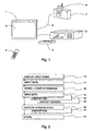
- Fig. 1 shows a TV receiver 1 and a video tape recorder 2 connected to the TV in a known manner for reading picture information from video cassettes 3 and displaying it on a television screen 4.
- the concept of picture information is to be understood as broadly as possible in this context because e.g. text on the TV screen is considered picture information by the TV and video tape recorder.
- the equipment usually includes a remote control device 5 which makes the use of the equipment easier but is not necessary as far as the present invention is concerned.
- Fig. 1 also shows a mobile phone 6 which represents the terminal of a bidirectional communications system.
- the equipment may comprise an ordinary phone, cordless phone, bidirectional paging device, fax machine or a corresponding apparatus; what is essential is that by means of the apparatus the equipment can send and receive information via a public telecommunications system.
- digital mobile phone it is preferable to use a digital mobile phone since digital communications provide more versatile features than analogue communications e.g. as regards encryption of information and use of error correction codes.
- the mobile phone is independent of wired connections it does not limit the use of the terminal according to the invention so as to be located near a telephone wall socket.
- the mobile phone 6 is connected to the terminal equipment constituting a TV and video tape recorder through an interface part 7 and local communications link 8.
- the communications link 8 comprises a wired connection coupled to the antenna connector, SCART connector, Euroconnector, Peritele connector or other corresponding video connector (not shown in the drawing) in the TV or video tape recorder. It could also be an infrared link or other known communications link suitable for local use.
- the interface part 7 is a so-called application-specific charger accessory the more detailed structure of which is not depicted in the drawing but which comprises, among other things, protocol converters used for making the conversions between the data format of the mobile phone and that of the TV-video tape recorder combination.
- the charger accessory 7 has got teletext capability and a picture dropper memory which can be used for the temporary storage of TV images at full resolution.
- the charger accessory 7 can store in the picture dropper memory an image on the TV screen 4 or an image read from a video cassette 3. It can also read an image from the picture dropper memory and display it on the TV screen 4 or store it via a video tape recorder 2 on a video cassette 3.
- Fig. 3 illustrates in block diagram format the structure and operation of an application-specific charger accessory.
- the charger accessory 30 (reference 7 in Fig. 1) has an antenna connector, SCART connector, Euroconnector, Peritele connector or other corresponding video connector 31 for connecting it in the manner described above to a TV set or video tape recorder or corresponding storage means as was described above.
- the charger accessory 30 also has a special, usually telephone manufacturer specific, connector 32 for connecting it to a mobile phone.
- the charger accessory has a PAL/SECAM/NTSC encoder 39 and a graphics chip 40 which includes a picture dropper memory 33 for the temporary storage of TV images, a field recognising and ordering unit 34, a certain number of field registers 35 and a corresponding number of video-data converters 36.
- the structure of the graphics chip shown in Fig. 3 is presented by way of example only; this component may also be a ready-made component such as a Siemens Megatext type chip, for example.
- the charger accessory further comprises a microprocessor (e.g. a 80C52 type microprocessor) as well as data registers 37 for storing data and a power supply 38 or power supply input.
- the field recognition and ordering unit 34 can extract from an image stored in the picture dropper memory 33 certain areas that are called fields and arrange them in a predetermined order such that the fields can be numbered from 1 to N where N is the maximum allowable number of fields.
- the field registers 35 are smallish memory units each of which holds a field, or a certain two-dimensional set of pixels, which is part of a TV image stored in the picture dropper memory 33. Instead of pixels the image may also be handled in bigger units, or blocks, so that each block may comprise, for example, 8 x 8 pixels. This makes the resolution of the picture poorer but at the same time reduces the need for memory capacity.
- Each field register is connected with a video-data converter 36, which is a kind of a bidirectional pattern recognition device, meaning that the video-data converter is able to convert a two-dimensional pixel or block set into a bit sequence and vice versa.
- the video-data converter recognises in the field the pixel sets that represent certain alphanumeric characters, for example, and converts them into ASCII codes representing the alphanumeric characters in question.
- Such a converter is known from various display devices, pattern recognition devices and other kinds of graphics chips.
- the video-data converters 36 communicate bidirectionally with the microprocessor and data register 37 so that a certain bit sequence can be compiled in a certain data register from the results yielded by the converters or, correspondingly, the bit sequence in a certain data register can be directed in parts to the converters in order to create the corresponding pixel or block sets.
- the microprocessor can direct the necessary data via the connector 32 to the mobile phone connected with it.
- the power supply 38 included in it has also got a feed voltage connection to the connector 32.
- the accessory 30 may include only a power supply input, whereby the accessory may be like a desktop stand for receiving a mobile phone at connector 32 and power from an external charger via power supply input 38.
- the connector 32 may include a data adapter or a data adapter may be connected between connector 32 and the mobile phone for adapting data for sending it over a mobile phone system, such as the GSM system, and also for adapting data received over the mobile phone system to a format suitable for graphics chip 40.
- a data adapter is known e.g. as data cards for connecting a computer to a mobile phone.
- the application-specific charger accessory according to Fig. 3 can be equipped with an infrared receiver with a connection to the microprocessor 37. Then the user is able to give commands direct to the charger accessory and via it to the mobile phone or other components of the equipment.
- a video tape recorder 2 reads from the video cassette a blank payment form displayed for the user on the TV screen 4.
- the blank payment form can be called generally an input form and its presentation to the user is the first stage 10 of the method in Fig. 2.
- the user enters the payment data by giving them as push-button commands on the remote control device 5.
- menus displayed by the TV can be applied.
- the data such as the bank account number of the payee, the amount payable and the reference number, are displayed in the respective fields of the payment form shown on the screen 4.
- This stage is called generally the entering of data and it is denoted by reference designator 11 in Fig. 2.
- the user gives a certain end command whereafter the completed payment form shown on the screen 4 is read into the picture dropper memory in the charger accessory 7.
- the charger accessory extracts the user input from the picture and converts it e.g. to a short message, which refers to a transmission format of relatively short character string type messages used in digital cellular radio systems. Instead of a short message the data can be transmitted as a data call. Storage of the image in the picture dropper memory and the consequent compilation of the message are depicted as one stage 12 in Fig. 2.
- the payment data are transferred to the bank via a mobile phone 6 and public telecommunications network.
- encryption and sender identity verification which are known procedures in the GSM system, for example, and based on the information stored in the SIM card (Subscriber Identity Module) of the mobile phone's owner.
- Sending of data and the possible encryption and sender identity verification are denoted by reference designators 13, 14 and 15 in Fig. 2.
- the acknowledgment is stored in the picture dropper memory of the charger accessory 7 advantageously in a field of that same picture which represented the transaction in the sending stage.
- the picture to which the acknowledgment is added can be displayed to the user on the TV screen 4 and is also stored on a video cassette 3 and protected against later editing and overwriting. If the system includes a printer, a hardcopy can be printed out of the receipted payment.
- the receipting and storing are denoted by reference designators 16 and 17 in Fig. 2.
- Providers of various services can easily apply the system according to the invention in accordance with their needs by preparing a video cassette which includes the required input forms and which is distributed to users.
- the input forms can also be transmitted as ordinary TV transmissions or even via the telephone system so that the user is able to record them on video tape for later use.
- the input forms distributed on video cassettes can also be personalised. For example, all input forms of a user can include the name of the user so that the user need not add it himself. Furthermore, a user with a poor eyesight can have his input forms with enlarged texts. Since the equipment formed of a video tape recorder and TV is also suitable for the playback of sound messages to the user, sound messages can be associated with certain input forms.
- banking service function described above is presented by way of example only and the invention can be used for offering many different services. If a service provider who wants to get a remuneration for the use of a service cannot debit the user's bank account direct, the service can be invoiced by adding the charge to the user's telephone bill.
- services the implementation of which can be derived from the banking service described above include the displaying of public transportation timetables and reservation of tickets, gallup polls, mail-order selling of various products, lotto, pools and betting services and, in connection with stock exchange activities, displaying of real-time information on stock exchange rates and making buy and sell orders.
- These different applications may be introduced into the equipment by purchasing a releasable memory, such as a video tape or a video disc, containing a specific application or data for a specific application (e.g. different forms for performing different kinds of banking operations).
- the input forms of the most frequently used services can also be stored in a semiconductor memory in the TV, video tape recorder or charger accessory so that they be quickly accessible and the user need not load them from the video cassette.
- the picture dropper memory described above may be included in the TV or video tape recorder instead of the charger accessory.
- the main reason for locating it in the charger accessory is the attempt to keep down the number of components added to the TV and video tape recorder to provide the home terminal equipment according to the invention.
- the invention is an obvious improvement from the prior art as it brings certain electrical services requiring bidirectional communications in a new manner available to a very large group of consumers. Consumers can use TVs and video tape recorders already in their homes by acquiring an interface unit by means of which a mobile phone or other terminal of a bidirectional communications system is connected to the home terminal equipment according to the invention.
Description
- The invention relates in general to bidirectional audiovisual terminals intended to be used by consumers and in particular to equipment the initial costs of which are low and the operation of which is based on combining known devices and utilising their characteristics in a new and inventional manner.
- Electrical telecommunications terminals intended for consumers can be divided into unidirectional and bidirectional devices. The most common unidirectional terminals are radio and television receivers. The most widely known bidirectional terminal has been, until recently, the telephone, but fax machines and computers with modems have now caught up with it. It has been suggested that a future home terminal equipment will be capable of transferring high-quality sound and images and other data bidirectionally in the form and at a time freely chosen by the user. So far, however, it has only been proposed equipments designed for certain limited applications, sharing a fairly high purchase price and a limited number of services available through them.
- Consumers often find it hard to understand why they should replace or supplement their existing and tried and proved terminals with a wholly new apparatus which, on top of it all, is also expensive. Considering the needs of conservative consumers it is better if they can be offered new services without considerable investments in unknown technology.
- Document EP 698 985 discloses an apparatus where a control apparatus uses a television as a graphical control interface. The control apparatus has an interface to the telephone network over which program code can be downloaded that can be used to interact with a service and to generate screens for the service on the television.
- An object of this invention is to provide a method and equipment for offering to the consumers new services based on bidirectional communications without the consumers being required to acquire new devices to a considerable extent.
- The objects of the invention are achieved by combining a TV receiver, video tape recorder and a terminal of a bidirectional communications system, advantageously a digital mobile phone. The TV shows the picture and text information to the user, the video tape recorder serves as a mass storage and as an input channel for new data, and the terminal of a bidirectional communications system relays information between the equipment and the outside world.
- The home terminal equipment according to the invention comprising a television and a terminal of a bi-directional communications system and means for transferring information between said television and said terminal of a bi-directional communications system for providing communication to and from a service provider over the bi-directional communications system, is characterized in that the home terminal equipment further comprises:
- external storage means connected locally to the television for providing an application to be used for communicating over said bi-directional communications system, said storage means adapted to receive releasable memories storing said application for allowing a user of the home terminal equipment to provide the equipment with the application stored in said releasable memories, said application including a data input form for display on said television;
- control means for selecting the service application and for entering data in the context of the input form; and
- a protocol converter adapted to convert the completed input form to a data message for communication over said bi-directional communications system.
-
- The invention is also directed to a method in a home terminal system for providing application services to a user, said system including, a television, a terminal of a bi-directional communications system, means for transferring information between said television and said terminal, and means for providing communication to and from said television over the bi-directional communications system, said system also including storage means communicating with said television, said storage means being adapted to receive releasable memories, wherein the method comprises the steps of:
- engaging a releasable memory storing an application in the storage means;
- transmitting data relating to said application over a local connection from the storage means to said television;
- displaying a certain input form for said application on said television;
- entering user specific data in the input form;
- reading said input form as an image;
- converting said user specific data image into a data message;
- transmitting said data message via the bi-directional communications system;
- receiving a data message response via the bi-directional communications system; and
- storing said response data message as an image in the storage means.
-
- The invention is based on the perception that a great number of consumers already have in their possession the required display, memory and communications capacity, so what is only needed is to harness it to operate in a new manner. A TV picture tube is an excellent large display device suitable for displaying both text and picture information to the user. In connection with the TV many consumers use a video tape recorder which essentially constitutes a high-capacity analogue mass storage. Any other similar storage means may be used as well, such as digital video storage means e.g. using digital discs for storage. Preferably a mass storage means like a video tape recorder is used, in which different applications may be applied by releasable memories, such as video tape. Different video tapes (different memory storage means) may thereby provide the user with data for using different applications. It can also be used as an input channel by acquiring a video cassette that contains the necessary data and inserting the cassette in the video tape recorder. When a telephone apparatus or other transceiver capable of transmitting and receiving information via a public telecommunications network is connected with this equipment, a multifunction home terminal equipment according to the present invention is produced.
- The invention is described in more detail with reference to the preferred embodiments presented by way of example and to the attached drawing in which
- Fig. 1
- shows in diagrammatic manner a home terminal equipment according to the invention,
- Fig. 2
- shows stages of the method according to a preferred embodiment of the invention, and
- Fig. 3
- shows in diagrammatic manner the operation of a component of a home terminal equipment according to the invention.
- Fig. 1 shows a
TV receiver 1 and avideo tape recorder 2 connected to the TV in a known manner for reading picture information fromvideo cassettes 3 and displaying it on atelevision screen 4. The concept of picture information is to be understood as broadly as possible in this context because e.g. text on the TV screen is considered picture information by the TV and video tape recorder. The equipment usually includes aremote control device 5 which makes the use of the equipment easier but is not necessary as far as the present invention is concerned. - Fig. 1 also shows a
mobile phone 6 which represents the terminal of a bidirectional communications system. Instead of a mobile phone the equipment may comprise an ordinary phone, cordless phone, bidirectional paging device, fax machine or a corresponding apparatus; what is essential is that by means of the apparatus the equipment can send and receive information via a public telecommunications system. As far as the invention is concerned, it is preferable to use a digital mobile phone since digital communications provide more versatile features than analogue communications e.g. as regards encryption of information and use of error correction codes. Additionally, as the mobile phone is independent of wired connections it does not limit the use of the terminal according to the invention so as to be located near a telephone wall socket. - The
mobile phone 6 is connected to the terminal equipment constituting a TV and video tape recorder through aninterface part 7 andlocal communications link 8. In the embodiment depicted in Fig. 1 thecommunications link 8 comprises a wired connection coupled to the antenna connector, SCART connector, Euroconnector, Peritele connector or other corresponding video connector (not shown in the drawing) in the TV or video tape recorder. It could also be an infrared link or other known communications link suitable for local use. In the embodiment of Fig. 1 theinterface part 7 is a so-called application-specific charger accessory the more detailed structure of which is not depicted in the drawing but which comprises, among other things, protocol converters used for making the conversions between the data format of the mobile phone and that of the TV-video tape recorder combination. In addition, thecharger accessory 7 has got teletext capability and a picture dropper memory which can be used for the temporary storage of TV images at full resolution. Thecharger accessory 7 can store in the picture dropper memory an image on theTV screen 4 or an image read from avideo cassette 3. It can also read an image from the picture dropper memory and display it on theTV screen 4 or store it via avideo tape recorder 2 on avideo cassette 3. - Fig. 3 illustrates in block diagram format the structure and operation of an application-specific charger accessory. The charger accessory 30 (
reference 7 in Fig. 1) has an antenna connector, SCART connector, Euroconnector, Peritele connector or othercorresponding video connector 31 for connecting it in the manner described above to a TV set or video tape recorder or corresponding storage means as was described above. Thecharger accessory 30 also has a special, usually telephone manufacturer specific,connector 32 for connecting it to a mobile phone. In addition, the charger accessory has a PAL/SECAM/NTSC encoder 39 and agraphics chip 40 which includes apicture dropper memory 33 for the temporary storage of TV images, a field recognising andordering unit 34, a certain number offield registers 35 and a corresponding number of video-data converters 36. The structure of the graphics chip shown in Fig. 3 is presented by way of example only; this component may also be a ready-made component such as a Siemens Megatext type chip, for example. The charger accessory further comprises a microprocessor (e.g. a 80C52 type microprocessor) as well asdata registers 37 for storing data and apower supply 38 or power supply input. The field recognition andordering unit 34 can extract from an image stored in thepicture dropper memory 33 certain areas that are called fields and arrange them in a predetermined order such that the fields can be numbered from 1 to N where N is the maximum allowable number of fields. Thefield registers 35 are smallish memory units each of which holds a field, or a certain two-dimensional set of pixels, which is part of a TV image stored in thepicture dropper memory 33. Instead of pixels the image may also be handled in bigger units, or blocks, so that each block may comprise, for example, 8 x 8 pixels. This makes the resolution of the picture poorer but at the same time reduces the need for memory capacity. - Each field register is connected with a video-
data converter 36, which is a kind of a bidirectional pattern recognition device, meaning that the video-data converter is able to convert a two-dimensional pixel or block set into a bit sequence and vice versa. The video-data converter recognises in the field the pixel sets that represent certain alphanumeric characters, for example, and converts them into ASCII codes representing the alphanumeric characters in question. Such a converter is known from various display devices, pattern recognition devices and other kinds of graphics chips. The video-data converters 36 communicate bidirectionally with the microprocessor and data register 37 so that a certain bit sequence can be compiled in a certain data register from the results yielded by the converters or, correspondingly, the bit sequence in a certain data register can be directed in parts to the converters in order to create the corresponding pixel or block sets. The microprocessor can direct the necessary data via theconnector 32 to the mobile phone connected with it. For the accessory 30 to be able to serve as a charger for the mobile phone's battery, thepower supply 38 included in it has also got a feed voltage connection to theconnector 32. The accessory 30 may include only a power supply input, whereby the accessory may be like a desktop stand for receiving a mobile phone atconnector 32 and power from an external charger viapower supply input 38. Theconnector 32 may include a data adapter or a data adapter may be connected betweenconnector 32 and the mobile phone for adapting data for sending it over a mobile phone system, such as the GSM system, and also for adapting data received over the mobile phone system to a format suitable forgraphics chip 40. Such a data adapter is known e.g. as data cards for connecting a computer to a mobile phone. - If the user intends to control the operation of the equipment using an infrared remote controller, the application-specific charger accessory according to Fig. 3 can be equipped with an infrared receiver with a connection to the
microprocessor 37. Then the user is able to give commands direct to the charger accessory and via it to the mobile phone or other components of the equipment. - Below, the method according to the invention is described with reference to the devices shown in Fig. 1 and the stages shown in Fig. 2. Let us assume that the user wants to use his terminal equipment as a banking terminal in which case one important function is to make a payment, or transfer money from a bank account to another. The user has earlier obtained from his bank a
video cassette 3 which contains various blank forms in picture format. In response to a command issued by means of aremote control device 5, which command may be based on control menus displayed by aTV set 1, avideo tape recorder 2 reads from the video cassette a blank payment form displayed for the user on theTV screen 4. The blank payment form can be called generally an input form and its presentation to the user is thefirst stage 10 of the method in Fig. 2. - The user enters the payment data by giving them as push-button commands on the
remote control device 5. Here, again, menus displayed by the TV can be applied. The data, such as the bank account number of the payee, the amount payable and the reference number, are displayed in the respective fields of the payment form shown on thescreen 4. This stage is called generally the entering of data and it is denoted byreference designator 11 in Fig. 2. When all the data have been entered, the user gives a certain end command whereafter the completed payment form shown on thescreen 4 is read into the picture dropper memory in thecharger accessory 7. The charger accessory extracts the user input from the picture and converts it e.g. to a short message, which refers to a transmission format of relatively short character string type messages used in digital cellular radio systems. Instead of a short message the data can be transmitted as a data call. Storage of the image in the picture dropper memory and the consequent compilation of the message are depicted as onestage 12 in Fig. 2. - Regardless of the transmission format the payment data are transferred to the bank via a
mobile phone 6 and public telecommunications network. In the case of banking services or other confidential messages it is usually necessary to use encryption and sender identity verification, which are known procedures in the GSM system, for example, and based on the information stored in the SIM card (Subscriber Identity Module) of the mobile phone's owner. Sending of data and the possible encryption and sender identity verification are denoted byreference designators mobile phone 6. Lest a dishonest user be able to receipt his bills himself, it is necessary to apply an encryption method to the acknowledgment as well. The acknowledgment is stored in the picture dropper memory of thecharger accessory 7 advantageously in a field of that same picture which represented the transaction in the sending stage. The picture to which the acknowledgment is added can be displayed to the user on theTV screen 4 and is also stored on avideo cassette 3 and protected against later editing and overwriting. If the system includes a printer, a hardcopy can be printed out of the receipted payment. The receipting and storing are denoted byreference designators - Providers of various services can easily apply the system according to the invention in accordance with their needs by preparing a video cassette which includes the required input forms and which is distributed to users. The input forms can also be transmitted as ordinary TV transmissions or even via the telephone system so that the user is able to record them on video tape for later use. The input forms distributed on video cassettes can also be personalised. For example, all input forms of a user can include the name of the user so that the user need not add it himself. Furthermore, a user with a poor eyesight can have his input forms with enlarged texts. Since the equipment formed of a video tape recorder and TV is also suitable for the playback of sound messages to the user, sound messages can be associated with certain input forms.
- It is obvious to one skilled in the art that the banking service function described above is presented by way of example only and the invention can be used for offering many different services. If a service provider who wants to get a remuneration for the use of a service cannot debit the user's bank account direct, the service can be invoiced by adding the charge to the user's telephone bill.
- Other examples of services the implementation of which can be derived from the banking service described above include the displaying of public transportation timetables and reservation of tickets, gallup polls, mail-order selling of various products, lotto, pools and betting services and, in connection with stock exchange activities, displaying of real-time information on stock exchange rates and making buy and sell orders. These different applications may be introduced into the equipment by purchasing a releasable memory, such as a video tape or a video disc, containing a specific application or data for a specific application (e.g. different forms for performing different kinds of banking operations). The input forms of the most frequently used services can also be stored in a semiconductor memory in the TV, video tape recorder or charger accessory so that they be quickly accessible and the user need not load them from the video cassette. Also the picture dropper memory described above may be included in the TV or video tape recorder instead of the charger accessory. The main reason for locating it in the charger accessory is the attempt to keep down the number of components added to the TV and video tape recorder to provide the home terminal equipment according to the invention.
- The invention is an obvious improvement from the prior art as it brings certain electrical services requiring bidirectional communications in a new manner available to a very large group of consumers. Consumers can use TVs and video tape recorders already in their homes by acquiring an interface unit by means of which a mobile phone or other terminal of a bidirectional communications system is connected to the home terminal equipment according to the invention.
Claims (19)
- Home terminal equipment comprising a television (1) and a terminal (6) of a bi-directional communications system and means (7,8) for transferring information between said television and said terminal of a bi-directional communications system for providing communication to and from a service provider over the bi-directional communications system, characterized in that the home terminal equipment further comprises:external storage means (2) connected locally to the television for providing an application to be used for communicating over said bi-directional communications system, said storage means (2) adapted to receive releasable memories (3) storing said application for allowing a user of the home terminal equipment to provide the equipment with the application stored in said releasable memories (3), said application including a data input form for display on said television;control means for selecting the service application and for entering data in the context of the input form; anda protocol converter (36) adapted to convert the completed input form to a data message for communication over said bi-directional communications system.
- The home terminal equipment of claim 1, characterised in that said terminal (6) of a bidirectional communications system is a telephone apparatus.
- The home terminal equipment of claim 1, characterised in that said terminal of a bidirectional communications system is a bidirectional paging device.
- The home terminal equipment of claim 1, characterised in that said terminal (6) of a bidirectional communications system is a computer.
- The home terminal equipment of claim 1, characterised in that the external storage means (2) is a video tape recorder and the releasable memories (3) are video tapes.
- The home terminal equipment of claim 1, characterised in that the releasable memories (3) are video discs.
- The home terminal equipment of claim 1, characterised in that the data message is a short message specified in a digital mobile network.
- The home terminal equipment of claim 1, characterised in that the terminal of a bi-directional communications system is configured to transmit the data message in a data call.
- The home terminal equipment of any one of the preceding claims, characterised in that the equipment comprises an accessory (7) connected to the terminal of the bidirectional communications system, said accessory comprisinga picture dropper memory for the temporary storage of picture information andthe protocol converter for converting information between the data transmission format applied by said bidirectional communications system and the data transmission format applied by said television.
- The home terminal equipment of claim 9, characterised in that said accessory (7) further comprises a charger device for charging the battery of a battery-operated apparatus connected to it.
- The home terminal equipment of claim 9, characterised in that said accessory further comprises wired connection means (8) to form a wired connection between said accessory and said television.
- A method in a home terminal system for providing application services to a user, said system including, a television (1), a terminal (6) of a bi-directional communications system, means (7,8) for transferring information between said television and said terminal, and means for providing communication to and from said television over the bi-directional communications system, said system also including storage means (2) communicating with said television, said storage means being adapted to receive releasable memories (3), wherein the method comprises the steps of:engaging a releasable memory (3) storing an application in the storage means (2);transmitting data relating to said application over a local connection from the storage means (2) to said television (1);displaying (10) a certain input form for said application on said television (1);entering (11) user specific data in the input form;reading said input form as an image;converting (12) said user specific data image into a data message;transmitting (13) said data message via the bi-directional communications system;receiving (16) a data message response via the bi-directional communications system; andstoring (17) said response data message as an image in the storage means.
- The method of claim 12, characterised in that said terminal (6) of a bidirectional communications system is a telephone apparatus.
- The method of claim 12, characterised in that said terminal of a bidirectional communications system is a bidirectional paging device.
- The method of claim 12, characterised in that said terminal (6) of a bidirectional communications system is a computer.
- The method of claim 12, characterised in that the external storage means (2) is a video tape recorder and the releasable memories (3) are video tapes.
- The method of claim 12, characterised in that the releasable memories (3) are video discs.
- The method of claim 12, characterised in that the data message is a short message specified in a digital mobile network.
- The method of claim 12, characterised in that the data message is transmitted in a data call.
Applications Claiming Priority (2)
| Application Number | Priority Date | Filing Date | Title |
|---|---|---|---|
| FI961800A FI115691B (en) | 1996-04-26 | 1996-04-26 | home terminal |
| FI961800 | 1996-04-26 |
Publications (3)
| Publication Number | Publication Date |
|---|---|
| EP0804030A2 EP0804030A2 (en) | 1997-10-29 |
| EP0804030A3 EP0804030A3 (en) | 1998-04-22 |
| EP0804030B1 true EP0804030B1 (en) | 2003-08-27 |
Family
ID=8545921
Family Applications (1)
| Application Number | Title | Priority Date | Filing Date |
|---|---|---|---|
| EP97660046A Expired - Lifetime EP0804030B1 (en) | 1996-04-26 | 1997-04-22 | Home terminal equipment |
Country Status (5)
| Country | Link |
|---|---|
| US (1) | US5990882A (en) |
| EP (1) | EP0804030B1 (en) |
| JP (1) | JP3939810B2 (en) |
| DE (1) | DE69724319T2 (en) |
| FI (1) | FI115691B (en) |
Families Citing this family (24)
| Publication number | Priority date | Publication date | Assignee | Title |
|---|---|---|---|---|
| JP3985204B2 (en) * | 1997-12-09 | 2007-10-03 | ソニー株式会社 | Information broadcasting method, receiver, information center, and receiving method |
| US6609113B1 (en) * | 1999-05-03 | 2003-08-19 | The Chase Manhattan Bank | Method and system for processing internet payments using the electronic funds transfer network |
| ATE307365T1 (en) | 1999-07-06 | 2005-11-15 | Swisscom Mobile Ag | METHOD FOR CHECKING TICKETS OF PUBLIC TRANSPORT USERS |
| DE19961575A1 (en) * | 1999-12-21 | 2001-07-05 | Bosch Gmbh Robert | Mobile phone with extended functionality |
| EP1117265A1 (en) * | 2000-01-15 | 2001-07-18 | Telefonaktiebolaget Lm Ericsson | Method and apparatus for global roaming |
| GB0009249D0 (en) | 2000-04-15 | 2000-05-31 | Koninkl Philips Electronics Nv | User profiling communications system |
| US6940562B2 (en) * | 2000-04-20 | 2005-09-06 | Canon Kabushiki Kaisha | Controller for remotely controlling two or more controlled devices |
| US6918131B1 (en) | 2000-07-10 | 2005-07-12 | Nokia Corporation | Systems and methods for characterizing television preferences over a wireless network |
| DE10062721A1 (en) * | 2000-12-15 | 2002-06-27 | Bernhard Walke | System for on-line polling and evaluation of broadcast users detects user actions and times at terminal input interface without disturbing use of service, transmits to evaluation computer |
| US7424201B2 (en) * | 2001-03-30 | 2008-09-09 | Sandisk 3D Llc | Method for field-programming a solid-state memory device with a digital media file |
| KR100407966B1 (en) * | 2001-08-24 | 2003-12-01 | 엘지전자 주식회사 | System and Method for Controlling Cellular Phone with TV |
| KR100416255B1 (en) * | 2001-09-29 | 2004-01-24 | 삼성전자주식회사 | Televsion having short message sevice function |
| WO2003032504A2 (en) * | 2001-10-12 | 2003-04-17 | Bellsouth Intellectual Property Corporation | Methods and systems of wireless communication between a remote data network and a set-top box |
| US8000647B2 (en) * | 2002-10-11 | 2011-08-16 | At&T Intellectual Property I, L.P. | Method using a set-top box and communicating between a remote data network and a wireless communication network |
| KR20050023640A (en) * | 2003-09-01 | 2005-03-10 | 엘지전자 주식회사 | Moving picture store apparatus and method in using camcoder type mobile communication terminal |
| EP1695538A2 (en) * | 2003-11-21 | 2006-08-30 | Interactive Systems Ltd | Mass viewer audience circuit based real time participation in interactive applications displayed live on display screens |
| US20140071818A1 (en) | 2004-07-16 | 2014-03-13 | Virginia Innovation Sciences, Inc. | Method and system for efficient communication |
| US7899492B2 (en) | 2004-07-16 | 2011-03-01 | Sellerbid, Inc. | Methods, systems and apparatus for displaying the multimedia information from wireless communication networks |
| US20070077784A1 (en) * | 2005-08-01 | 2007-04-05 | Universal Electronics Inc. | System and method for accessing a user interface via a secondary device |
| US20080084477A1 (en) * | 2005-10-14 | 2008-04-10 | Crouse Timothy C | Image transmission device and system |
| US8225366B2 (en) | 2007-10-30 | 2012-07-17 | Sony Corporation | Wireless control channel and back-channel for receiver |
| US8538324B2 (en) * | 2009-02-03 | 2013-09-17 | Sony Corporation | Mobile phone dock for TV |
| US20100197345A1 (en) * | 2009-02-03 | 2010-08-05 | Ahmed Ali Ahmed Bawareth | Remote video recorder for a mobile phone |
| US20110051716A1 (en) * | 2009-09-03 | 2011-03-03 | Sony Corporation | Tv acting as pots phone switch |
Family Cites Families (10)
| Publication number | Priority date | Publication date | Assignee | Title |
|---|---|---|---|---|
| US4451701A (en) * | 1980-10-30 | 1984-05-29 | Oclc Online Computer Library Center, Incorporated | Viewdata system and apparatus |
| US4689022A (en) * | 1984-04-30 | 1987-08-25 | John Peers | System for control of a video storage means by a programmed processor |
| US4987486A (en) * | 1988-12-23 | 1991-01-22 | Scientific-Atlanta, Inc. | Automatic interactive television terminal configuration |
| US5077607A (en) * | 1988-12-23 | 1991-12-31 | Scientific-Atlanta, Inc. | Cable television transaction terminal |
| US5327554A (en) * | 1990-11-29 | 1994-07-05 | Palazzi Iii Michael A | Interactive terminal for the access of remote database information |
| US5341166A (en) * | 1992-02-27 | 1994-08-23 | Video Control Technology, Inc. | System for controlling selected devices having unique sets of control codes |
| US5357276A (en) * | 1992-12-01 | 1994-10-18 | Scientific-Atlanta, Inc. | Method of providing video on demand with VCR like functions |
| CA2109011C (en) * | 1993-10-22 | 1999-09-07 | Michael D. Bell | Apparatus for television display of telephone audio and data dialog |
| US5706334A (en) * | 1994-08-18 | 1998-01-06 | Lucent Technologies Inc. | Apparatus for providing a graphical control interface |
| CN1096796C (en) * | 1996-02-23 | 2002-12-18 | E盖德公司 | Two-way interactive television system |
-
1996
- 1996-04-26 FI FI961800A patent/FI115691B/en not_active IP Right Cessation
-
1997
- 1997-04-22 DE DE69724319T patent/DE69724319T2/en not_active Expired - Lifetime
- 1997-04-22 EP EP97660046A patent/EP0804030B1/en not_active Expired - Lifetime
- 1997-04-24 US US08/847,291 patent/US5990882A/en not_active Expired - Lifetime
- 1997-04-25 JP JP10919697A patent/JP3939810B2/en not_active Expired - Fee Related
Also Published As
| Publication number | Publication date |
|---|---|
| US5990882A (en) | 1999-11-23 |
| FI115691B (en) | 2005-06-15 |
| JPH1084537A (en) | 1998-03-31 |
| FI961800A (en) | 1997-10-27 |
| DE69724319T2 (en) | 2004-06-03 |
| EP0804030A3 (en) | 1998-04-22 |
| DE69724319D1 (en) | 2003-10-02 |
| FI961800A0 (en) | 1996-04-26 |
| EP0804030A2 (en) | 1997-10-29 |
| JP3939810B2 (en) | 2007-07-04 |
Similar Documents
| Publication | Publication Date | Title |
|---|---|---|
| EP0804030B1 (en) | Home terminal equipment | |
| EP0804012B1 (en) | Multimedia terminal and method for realising multimedia reception | |
| US5884140A (en) | Information distributing system with sub-stations transmitting broadcast information by wireless and terminals receiving the information | |
| US5995592A (en) | Portable telephone unit and indication adapter | |
| TW480449B (en) | Chipcard and method for the communication between an external device and a chipcard | |
| US6036086A (en) | Apparatus and method for initiating a telephone transaction using a scanner | |
| CA2335996C (en) | Display device for displaying received information and for transmitting received digital data to external mobile apparatuses and corresponding request method | |
| US4071697A (en) | Interactive video/telephone transmission system | |
| RU2195083C2 (en) | Broadcasting and reception of tv programs and other data | |
| US6330021B1 (en) | Interactive television reception console | |
| JP2001333414A (en) | Program information distributor and method and terminal and system relating thereto | |
| EP1703732A1 (en) | Television receiver and digital broadcast system | |
| KR20010108113A (en) | Telephone handset for use in interactive tv systems | |
| KR20010110344A (en) | Bidirectional real-time advertisement system | |
| US5869821A (en) | Credit inquiry service system and method | |
| CN100382575C (en) | Creating effects for images | |
| US7941125B2 (en) | Mobile telephone-based system and method for automated data input | |
| EP0796014A1 (en) | Bidirectional information system and device | |
| JP2001136136A (en) | Terminal, control method and recording medium recording program | |
| GB2338387A (en) | Information providing system | |
| JP2005122516A (en) | Ordering system and portable terminal | |
| JP2003085658A (en) | Pos transaction managing method and pos transaction managing system utilizing portable telephone | |
| EP0790733A2 (en) | System for the carrying out of interactive services between a central unit and a plurality of users | |
| JP2003163920A (en) | Digital broadcast system, ic card therein, electronic money using method, receiving terminal, electronic money using program and computer readable recording medium with records of electronic money using program | |
| KR20010081522A (en) | Telephone for use in a CTI system |
Legal Events
| Date | Code | Title | Description |
|---|---|---|---|
| PUAI | Public reference made under article 153(3) epc to a published international application that has entered the european phase |
Free format text: ORIGINAL CODE: 0009012 |
|
| AK | Designated contracting states |
Kind code of ref document: A2 Designated state(s): DE FR GB SE |
|
| PUAL | Search report despatched |
Free format text: ORIGINAL CODE: 0009013 |
|
| AK | Designated contracting states |
Kind code of ref document: A3 Designated state(s): DE FR GB SE |
|
| 17P | Request for examination filed |
Effective date: 19981022 |
|
| 17Q | First examination report despatched |
Effective date: 20020111 |
|
| RAP1 | Party data changed (applicant data changed or rights of an application transferred) |
Owner name: NOKIA CORPORATION |
|
| GRAH | Despatch of communication of intention to grant a patent |
Free format text: ORIGINAL CODE: EPIDOS IGRA |
|
| GRAS | Grant fee paid |
Free format text: ORIGINAL CODE: EPIDOSNIGR3 |
|
| GRAA | (expected) grant |
Free format text: ORIGINAL CODE: 0009210 |
|
| AK | Designated contracting states |
Designated state(s): DE FR GB SE |
|
| REG | Reference to a national code |
Ref country code: GB Ref legal event code: FG4D |
|
| REF | Corresponds to: |
Ref document number: 69724319 Country of ref document: DE Date of ref document: 20031002 Kind code of ref document: P |
|
| REG | Reference to a national code |
Ref country code: SE Ref legal event code: TRGR |
|
| ET | Fr: translation filed | ||
| PLBQ | Unpublished change to opponent data |
Free format text: ORIGINAL CODE: EPIDOS OPPO |
|
| PLBI | Opposition filed |
Free format text: ORIGINAL CODE: 0009260 |
|
| PLAX | Notice of opposition and request to file observation + time limit sent |
Free format text: ORIGINAL CODE: EPIDOSNOBS2 |
|
| 26 | Opposition filed |
Opponent name: INTERESSENGEMEINSCHAFTFUER RUNDFUNKSCHUTZRECHTE E. Effective date: 20040525 |
|
| PLBB | Reply of patent proprietor to notice(s) of opposition received |
Free format text: ORIGINAL CODE: EPIDOSNOBS3 |
|
| PLCK | Communication despatched that opposition was rejected |
Free format text: ORIGINAL CODE: EPIDOSNREJ1 |
|
| PLBN | Opposition rejected |
Free format text: ORIGINAL CODE: 0009273 |
|
| STAA | Information on the status of an ep patent application or granted ep patent |
Free format text: STATUS: OPPOSITION REJECTED |
|
| 27O | Opposition rejected |
Effective date: 20091108 |
|
| PGFP | Annual fee paid to national office [announced via postgrant information from national office to epo] |
Ref country code: SE Payment date: 20110412 Year of fee payment: 15 Ref country code: FR Payment date: 20110426 Year of fee payment: 15 |
|
| PGFP | Annual fee paid to national office [announced via postgrant information from national office to epo] |
Ref country code: GB Payment date: 20110420 Year of fee payment: 15 |
|
| REG | Reference to a national code |
Ref country code: SE Ref legal event code: EUG |
|
| GBPC | Gb: european patent ceased through non-payment of renewal fee |
Effective date: 20120422 |
|
| REG | Reference to a national code |
Ref country code: FR Ref legal event code: ST Effective date: 20121228 |
|
| PG25 | Lapsed in a contracting state [announced via postgrant information from national office to epo] |
Ref country code: GB Free format text: LAPSE BECAUSE OF NON-PAYMENT OF DUE FEES Effective date: 20120422 |
|
| PG25 | Lapsed in a contracting state [announced via postgrant information from national office to epo] |
Ref country code: FR Free format text: LAPSE BECAUSE OF NON-PAYMENT OF DUE FEES Effective date: 20120430 Ref country code: SE Free format text: LAPSE BECAUSE OF NON-PAYMENT OF DUE FEES Effective date: 20120423 |
|
| REG | Reference to a national code |
Ref country code: DE Ref legal event code: R082 Ref document number: 69724319 Country of ref document: DE Representative=s name: BECKER, KURIG, STRAUS, DE Ref country code: DE Ref legal event code: R081 Ref document number: 69724319 Country of ref document: DE Owner name: NOKIA TECHNOLOGIES OY, FI Free format text: FORMER OWNER: NOKIA CORP., 02610 ESPOO, FI |
|
| PGFP | Annual fee paid to national office [announced via postgrant information from national office to epo] |
Ref country code: DE Payment date: 20160419 Year of fee payment: 20 |
|
| REG | Reference to a national code |
Ref country code: DE Ref legal event code: R071 Ref document number: 69724319 Country of ref document: DE |
|
| REG | Reference to a national code |
Ref country code: DE Ref legal event code: R082 Ref document number: 69724319 Country of ref document: DE Representative=s name: BARKHOFF REIMANN VOSSIUS, DE Ref country code: DE Ref legal event code: R081 Ref document number: 69724319 Country of ref document: DE Owner name: WSOU INVESTMENTS, LLC, LOS ANGELES, US Free format text: FORMER OWNER: NOKIA TECHNOLOGIES OY, ESPOO, FI |