EP0806251B1 - Apparatus for sorting various kinds of sheets of paper - Google Patents
Apparatus for sorting various kinds of sheets of paper Download PDFInfo
- Publication number
- EP0806251B1 EP0806251B1 EP97301614A EP97301614A EP0806251B1 EP 0806251 B1 EP0806251 B1 EP 0806251B1 EP 97301614 A EP97301614 A EP 97301614A EP 97301614 A EP97301614 A EP 97301614A EP 0806251 B1 EP0806251 B1 EP 0806251B1
- Authority
- EP
- European Patent Office
- Prior art keywords
- sheets
- sorting
- section
- conveying path
- separating
- Prior art date
- Legal status (The legal status is an assumption and is not a legal conclusion. Google has not performed a legal analysis and makes no representation as to the accuracy of the status listed.)
- Expired - Lifetime
Links
- 230000007246 mechanism Effects 0.000 claims description 55
- 238000007639 printing Methods 0.000 claims description 53
- 239000011159 matrix material Substances 0.000 claims description 3
- 238000010276 construction Methods 0.000 description 37
- 230000000694 effects Effects 0.000 description 10
- 238000000034 method Methods 0.000 description 9
- 238000005516 engineering process Methods 0.000 description 7
- 238000010586 diagram Methods 0.000 description 4
- 230000002708 enhancing effect Effects 0.000 description 4
- 230000001965 increasing effect Effects 0.000 description 4
- 230000008569 process Effects 0.000 description 4
- 230000007306 turnover Effects 0.000 description 4
- 230000009466 transformation Effects 0.000 description 3
- 230000008901 benefit Effects 0.000 description 2
- 230000008859 change Effects 0.000 description 2
- 230000002411 adverse Effects 0.000 description 1
- 238000005452 bending Methods 0.000 description 1
- 230000006735 deficit Effects 0.000 description 1
- 230000001419 dependent effect Effects 0.000 description 1
- 230000001771 impaired effect Effects 0.000 description 1
- 230000006872 improvement Effects 0.000 description 1
- 230000010365 information processing Effects 0.000 description 1
Images


Classifications
-
- B—PERFORMING OPERATIONS; TRANSPORTING
- B07—SEPARATING SOLIDS FROM SOLIDS; SORTING
- B07C—POSTAL SORTING; SORTING INDIVIDUAL ARTICLES, OR BULK MATERIAL FIT TO BE SORTED PIECE-MEAL, e.g. BY PICKING
- B07C3/00—Sorting according to destination
- B07C3/02—Apparatus characterised by the means used for distribution
- B07C3/08—Apparatus characterised by the means used for distribution using arrangements of conveyors
Definitions
- the present invention relates to technology about sorting various kinds of sheets of paper, and more particularly to the technology which may be effectively applied to the sorting of various kinds of sheets of paper such as postcards and cards used in an information processing field.
- the operation is executed to recognize character information containing a zip code and an address described on each postcard through the effect of the known OCR technology and activate a distributing mechanism in concert with the recognizing operation for automatically distributing the postcards to the corresponding destination areas.
- This operation makes it possible to achieve a saving in labor and speed up the work.
- Figs. 10A and 10B illustrate an exemplary system for conveying various kinds of sheets of paper 10 (simply called sheets).
- the sheets 10 are separated one by one by a separating mechanism 1011 located in a separating section 1001 so that each sheet is transferred to a conveying path.
- a numeral 1012 denotes a recognizing mechanism, which reads, for example, an address described in each sheet and then recognizes the read address through a desired algorithm stored in a computer. The time consumed by the recognition depends on the conveying path on which the sheets are conveyed.
- this conveying path is located in a space 5 secured under the lowest row of boxes 1041 of a sorting section 1044.
- the characters of the address for example, are recognized.
- the postcard is sorted into the corresponding box 1041 through the effect of the sorting section 1044.
- the recognizing mechanism 1012 and the sorting section 1044 the postcard must be rejected.
- the frequent rejections become an obstacle to enhancing the operativity of the sorting apparatus.
- the improvement of the recognition factor is important in enhancing the operativity of the sorting apparatus. For quickly recognizing various kinds of characters, there must be provided an expensive computer for achieving the fast processing.
- the video coding system does not need an expensive computer for recognizing the characters but needs a considerable length of time in the operator's recognition and input of the character information. Hence, this considerable length of time requires a long conveying path accordingly.
- the long conveying path burdens the apparatus with a technical issue. That is, it needs an additional path to the outside of the apparatus, so that the path makes the apparatus larger in size. The resulting longer apparatus is not allowed to be stored a limited area, thereby making the installing area of the apparatus wider.
- the system currently employed about this point may be roughly divided into two systems, that is, a constant pitch system (see Fig. 10A) and a constant gap system (see Fig. 10B).
- the constant pitch system is arranged to keep the distance (pitch P) between the tail end of the leading sheet 10 and the tail end of the succeeding sheet 10 constant.
- the constant gap system is arranged to keep the distance (gap G) between the tail end of the leading sheet 10 and the front end of the succeeding sheet 10.
- the separating mechanism 1011 located in the conventional separating section 1001 is consructed to separate the sheets 10 horizontally arranged in a standing manner toward the upward part from the ranging end.
- the constant pitch system is advantageous in this construction. This is because since the feeding lengths of the sheets 10 are various, if the constant pitch system is employed, the upwardly separating system may be implemented by such a simple control operation as sending the tail end of the leading sheet 10 and then feeding out the succeeding sheet 10 after a predetermined time defined by the feeding speed and the pitch.
- a bypass located in a narrower space entails a smaller curvature.
- the bypass with a small curvature puts a burden on the sheets, so that the sheets may be impaired and often jammed.
- the box 1041 located in the sorting section 1044 has a gate 1042 for opening or shutting the sheet.
- a short pitch may cause an erroneous operation or jamming.
- the pitch is considered to be far larger than each length of the variable sheets 10.
- the pitch is larger than necessary, the number of the sheets 10 to be processed at a unit time, that is, a throughput is made lower.
- the constant gap system is used for the main current of the prior arts, that is, the upwardly separating system, it may puts another technical problem. That is, one alternative has to be selected, a lower throughput required in the case of considering the variable lengths (heights) or a wider pitch P required in the case of speeding up the conveying speed.
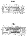
- Fig. 1 is a conceptual view showing a construction of an apparatus for sorting sheets according to a first embodiment of the present invention.
- Fig. 8 is a side view showing a part cut out of the apparatus shown in Fig. 1.
- Fig. 11 is a conceptual view showing the transformation of the apparatus shown in Fig. 1.
- the apparatus for sorting sheets includes a sorting section 4 having locating plural boxes 40 arranged in a matrix manner, a separating section 1 located in the left hand of the sorting section 4 (as viewed from the front of this Figure), and a printing section 3 located in the right hand of the sorting section 4.
- the separating section 1 is constructed to have a separating mechanism 11 for feeding the sheets 10 one by one, a recognizing mechanism 12 for scanning character information such as an address and a zip code described on each of the sheets 10 and a conveying path 13 for sequentially passing a bar code scanning unit 12a for scanning the bar code information and the like.
- the bar code scanning unit 12a is served to scan the bar code information printed on the sheet 10 in place of the character information (which will be discussed below).
- the printing section 3 includes a printing mechanism 31 for converting the recognized result of each sheet 10 given by the recognizing mechanism 12 which is a recognition computer (not shown) into the bar code informatoin and printing the bar code information on part of each sheet 10, a verifying mechanism 31a for scanning the bar code information printed by the printing mechanism 31 and checking if the bar code is precisely printed, and a conveying path 32 for the printing section for feeding the sheet 10 with the bar code printed thereon to the sorting section 4.
- the connecting section of the conveying path 32 with the sorting section 4 is branched into the conveying paths (not shown). Those branched paths correspond to the rows of the boxes 40 (from the uppermost box 42 to the lowermost one 41) arranged in a matrix manner, respectively.
- the connecting section is constructed to distribute the sheets 10 into each box row according to the recognized result given by the foregoing recognizing mechanism 12 or the bar code scanning unit 12a.
- Each box 40 of the sorting section 4 provides a gate 40a on the conveying path (not shown) located in the upper part of the sorting section 4.
- the gate 40a is allowed to be individually opened or shut. In operation, the gate 40a is opened on the timing when the corresponding sheet 10 is passed according to the recognized result given by the recognizing mechanism 12 and the bar code scanning unit 12a located in the separating section 1. With the opening of the gate 40a, the specific sheet 10 is taken to the sorting section 4 according to the character information or the bar code information described on the sheet 10. If unrecognized sheets 10 (containing the sheets that are not recognized until they reach the sorting section 4) are stored in the leftmost box 40 that is the nearest to the separating section 1 or a given box 40.
- the separating mechanism 11 includes a feeding platform 11a on which the sheets 10 are placed in a standing manner so as to justify their lower ends, a pusher 11b for horizontally pressing the sheets from one end to the other one of the platform 11a, a feeding roller 11c for substantially vertically and downwardly feeding the sheets 10 being pressed out to the other end, sensors 11d for sensing the tail ends of the sheets coming from the feeding roller 11c located in the upper part, and a selector 11e for selecting any one of the outputs of the sensors 11d and sending out the output to a control system for controlling the operation timing of the feeding roller 11c.
- the operation is executed for continuously feeding out sheets 10 in the constant gap system by operating the feeding roller 11c for feeding out the succeeding sheet 10.
- the outputs of the sensors 11d apart from the feeding roller 11c the height of the plane of the platform 11a
- the separating mechanism 11 makes it possible to easily implement the conveying method of the constant gap system by feeding out the sheets 10 downwardly without being adversely effected by the variety of the lengths of the sheets. This is because the apparatus for sorting the sheets according to the present invention treats the sheets with respective lengths.
- the delaying conveying path 21 is located in the upper space of the uppermost box 42 contained in the sorting section 4 shown in Fig. 1.
- the time required for the passage compensates for a time required for character recognition done by the recognizing mechanism (recognition computer) located in the separating section 1 or bar code recognition done by the bar code scanning unit 12a.
- the conveying path 13 of the separating mechanism is circulated clockwise as viewed from the front of Fig. 1, concretely, in the sequence of the recognizing mechanism 12 and the bar code scanning unit 12a and then is smoothly connected to the delaying conveying path 21 in the upper part of the separating section 1.
- the delaying conveying path 21 is located on the upper part of the sorting section 4.
- the conveyance of the sheets 10 in the printing section 3 is made smoother.
- the sheets 10 are separated downwardly one by one through the effect of the separating mechanism 11 in the constant gap system, so that each sheet is smoothly passed to the conveying path 32 of the printing section.
- the separated sheet 10 passes through the recognizing mechanism 12 and then the delaying conveying path 21 that is provided in the upper space of the uppermost box 42 of the sorting section 4. Finally, the sheet is conveyed to the printing mechanism 31 of the printing section 3.
- the operation is executed to recognize the characters described on the sheet 10 based on the picture data scanned by the recognizing mechanism 12 for recognizing the characters of the sheet 10, convert the recognized characters into the corresponding bar code, and print the bar code on the sheet 10 through the effect of the printing mechanism 31.
- the verifying mechanism 31a operates to check if the bar code is precisely printed by the scanning operation immediately after printing. Then, the sheet 10 on which the bar code is printed is conveyed to the sorting section 4 by the conveying path 32 of the printing section.
- the sorting section 4 operates to group the sheets to each horizontal row and then more definitely to each box 40 on the row according to the recognized result given by the recognizing mechanism 12.
- each post office provides the apparatus for sorting the sheets according to this embodiment, since the sheets 10 coming from another post office have already contained the bar codes described thereon by the printing mechanism 31 as described with respect to Fig. 1, the subject post office does not need to operate the recognizing mechanism 12 for the character recognition because the recognition has been already finished. Hence, the subject post office just needs to scan the bar code through the effect of the bar code scanning unit 12a when the post office collects and delivers the postal matters.
- the subject post office does not need to have the step of recognizing the characters through the recognizing mechanism 12 and enables to recognize the data of each sheet 10 only through the bar code scanning unit 12a. This is thus effective in reducing the processing time, that is, the sorting time because the complicated character recognition is not necessary to the subject post office.
- the apparatus for sorting the sheets may provide a mode switching function (not shown) for switching the operation from the recognizing mechanism 12 to the bar code scanning unit 12a or vice versa.
- the recognizing mechanism may provide a function of determining whether or not the bar code is printed. If the bar code has been printed on the sheet 10, the sheet 10 passes by the recognizing mechanism 12. Then, the bar code scanning unit 12a is automatically started. According to the scan result of the bar code scanning unit 12a, each box 40 located in the sorting section 4 at a later stage may be controlled. For this purpose, the printing and the verifying functions of the printing section 3 are suppressed. As mentioned above, the bar code scan is far faster and more precisely than the normal character recognition, which leads to implementing a faster sorting process.
- Fig. 1 The construction shown in Fig. 1 is divided into the bar code scanning unit 12a and the recognizing mechanism 12.
- the recognizing mechanism 12 may have a function of scanning a bar code.
- each section such as the separating section 1 or the printing mechanism 31 is controlled by a control unit (not shown).
- the apparatus for sorting the sheets according to this embodiment of the invention is constructed to feed out the sheets 10 downwardly through the effect of the separating mechanism 11.
- This construction makes it possible to do the conveying operation in the constant gap system with a simple mechanism independently of the dimensional variety of the sheets and achieve a high throughput that is an advantage of the constant gap system.
- the delaying conveying path 21 in the upper portion of the sorting section 4 makes it possible to obtain the length of the delaying conveying path 21 and thereby extend the recognition time of the recognizing mechanism 12 without making the overall apparatus bulky.
- This construction is effective in enhancing the accuracy of the recognized result and eliminating the troublesome works such as person's manual intervention to the process.
- the printing section 3 is operated to convert the recognized result of the recognizing mechanism 12 into the corresponding bar code and put it on each sheet 10. This operation makes the fringe works such as collection and delivery more efficient.
- a delaying conveying path 21a may be located in a lower space 5 of the sorting section 4 for connecting the printing section 3 to the sorting section 4 in addition to the delaying conveying path 2 passing the upper space 2 of the sorting section 4.
- the separating section 1 operates to downwardly separate the sheets 10 in the constant gap system as described with respect to Fig. 1.
- the sheets are circulated clockwise as viewed from the front.
- the delaying conveying paths are provided in the upper and the lower portions of the sorting section 4 so that the separating section 1, the printing section 3, and the sorting section 4 are smoothly connected by the conveying paths.
- the construction shown in Fig. 11 makes it possible to secure the length of the delaying conveying path 21 and thereby extending the recognizing time consumed by the recognizing mechanism 12 more than the construction shown in Fig. 1 without making the overall apparatus bulky. This construction is effective in enhancing the accuracy of the recognized result more.
- the description will be oriented to the method for displaying the character information cut by the recognizing mechanism 12 on a CRT and entering the unrecognized portion with person's hands (called a video coding method).
- This method is used if some of the scanned characters are not recognized or a long time is consumed in recognizing the characters.
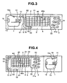
- Fig. 2 is a construction plan showing a construction of an apparatus for sorting sheets according to the second embodiment of the present invention.
- Fig. 9 is a block diagram showing an arrangement of a control system.
- a control computer (or simply called a control unit) 71 controls the overall operation of all sections including the separating section 1 to the sorting sections.
- the recognizing mechanism 12 is connected to a recognition computer 72 dedicated to recognition.
- the recognition computer 72 is operated in concert with the control computer 71 for the purpose of transferring the recognized result, for example.
- the recognition computer 72 is also connected to a video control computer 73 for supporting the vide coding, a display 74 for indicating the data such as a picture to an operator, a keyboard 75 on which code data or something is entered, a data disk 76 for saving the unrecognized picture data, and so forth.
- Fig. 9 illustrates the control computer 71, the recognition computer 72, and the video control computer 73 for the explanation's sake.
- Those computers may be implemented by an inexpensive computer having a large processing capability.
- a bypass is added to the construction of the foregoing embodiment 1.
- the bypass is provided in the lower space 5 of the lowermost box 41 located in the sorting section 4 in order that the bypass consumes a proper time for this purpose.
- the conveying path 13 of the separating section 1 is connected to the conveying path 61 of the connecting section 6 coming downwardly so that the sheets are conveyed to the bypass conveying path 51 passing through the lower space 5 of the sorting section.
- the bypass conveying path 51 goes around in the bypass portion 53 and then the bypass conveying path 52 is connected with the conveying path 62 of the connecting section 6 coming upwardly.
- the conveying path 62 is connected with the delaying conveying path 21 located in the upper space 2 of the sorting section 4 so that the sheets 10 are conveyed from the sorting section 4 to the printing section 3. While the sheets are passed through the bypass conveying paths 51 and 52 and the delaying conveying path 21, the person's input data is converted into the corresponding bar code and the bar code is printed on the corresponding sheet 10 by the printing mechanism 31.
- the bypass conveying paths 51 and 52 may be set to have a shorter length. As is illustrated in Fig. 3, as compared with the construction shown in Fig. 2, the bypass 53 is located in the left hand as viewed from the front of the drawing, so that the horizontal distance between the separating section 1 and the bypass 53 is made shorter.
- the delaying conveying path 21 located in the upper part of the sorting section 4 is made longer.
- the delaying conveying path located in the bypass may be made shorter because the overall length of the delaying conveying path for recognizing the characters is the same as the length of the above case.
- the sorting section 4 is required to make the boxes 40 as numerous as possible and the box rows are preferably increased in number.
- the lower space 5 is made narrower, so that it is better to put the conveying path 32 of the printing section to the boxes 40 from the lower portion in light of the connectivity of the conveying paths from the printing section 3 to the sorting section 4.
- the conveying path 32 of the printing section is provided under the apparatus with no substantial gap therebetween.
- the vertical direction of the bypass portion 53 of the bypasses 51 and 52 is optionally set in order not to be overlapped with the conveying path 32 led from the printing section 3 to the sorting section 4.
- the conveying path 32 of the printing section is allowed to be guided from a far lower portion to the sorting section 4, it is possible to keep a wide space of the sorting section 4 and increase the box rows in number as keeping the connectivity between the conveying paths.
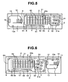
- Fig. 4 is a conceptual view showing a construction of an apparatus for sorting sheets according to a third embodiment of the present invention.
- This apparatus provides the conveying path changed according to the relocation of the separating section.
- the apparatus according to the third embodiment of the invention is arranged to have the printing section 3 and the separating section 1 collectively located in the right hand of the sorting section 4 (as viewed from the front of the drawing).
- the apparatus is divided into the sorting section 4 with which the operator often manually concerns for taking out the postcards, for example, and the other sections (separating section 1 and printing section 3) that need no substantial manual operation.
- This construction makes it easier to maintain this apparatus.
- the conveying path 13 of the separating section 1 may be connected to the delaying conveying path 21 as described with respect to Fig. 1 only if the delaying conveying path 21 is extended by the width of the printing section 3. It means that the construction of the separating section 1 does not need any large change.
- the inlet of the conveying path 32 of the printing section 3 is just connected to the delaying conveying path 22 located in the sorting section 4 in parallel to the delaying conveying path 21. No large change is required for the construction of the printing section 3. That is, the separating section 1 may be located selectively in the left hand of the sorting section 4 as shown in Figs. 1 and 2 or in the right hand of the sorting section 4 as shown in Fig. 4.
- the overall delaying conveying path is made longer by the length of the delaying conveying path 22, so that the length of the bypass 53 (bypass conveying paths 51 and 52) located in the lower portion of the sorting section 4 may be shorter accordingly. It means that the bypass portion 53 located in the lower space 5 may be relocated in order not to interfere with the conveying path 32 of the printing section 3. Hence, the bypass is not overlapped with the conveying path 23 of the printing section 3.
- the conveyance of the sheets 10 is likewise to that described with respect to Fig. 2.
- Fig. 5 is a view showing a construction of the apparatus for sorting sheets according to a fourth embodiment of the present invention.
- the separating section 8 operates to separate the sheets upwardly.
- Each sheet separated by the separating section 8 passes through the recognizing mechanism 12 and the bar code scanning unit 12a and then is sent to the bypass conveying path 51 located in the lower space 5 of the sorting section 4.
- the sheet is bypassed around the bypass portion 53 and is conveyed on the bypass conveying path 52.
- the bypass conveying path 52 is connected with a conveying path 61 of a connecting section 6.
- the conveying path 61 is connected with the delaying conveying path 21 located in the upper portion of the sorting section 4 and then is conveyed to the printing section 3.
- the printing mechanism 31 operates to print a bar code on the sheet 10 conveyed thereto.
- the sheet with the bar code printed thereon is verified by the verifying mechanism 31a.
- the sheet 10 on which the bar code is printed is conveyed to the sorting section 4 through the conveying path 32 of the printing section and then is sorted to the destination box.
- the foregoing construction has the following advantage.
- the conveying path 13 of the separating section is circulated counterclockwise, so that the conveying path 13 may be smoothly and unbendably connected to the bypass conveying path 51 located in the lower portion of the sorting section 4.
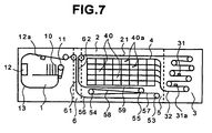
- Figs. 6 and 7 show the construction of the apparatus for sorting the sheets according to a fifth embodiment of the present invention.
- Fig. 6 shows the construction of the sorting section and the other sections.
- Fig. 7 shows the construction having the sorting section described with respect to Fig. 1 located in the center of the figure.
- three bypass portions 53, 54, and 55 are located in the lower space 5 of the sorting section 4 so that the corresponding bypass conveying paths 56, 57, 58, and 59 are located in the lower space 5.
- the printing section 3 and the separating section 1 are collectively located in the right hand of the sorting section 4.
- the sheets 10 processed by the recognizing mechanism 12 and the bar code scanning unit 12a located in the separating section 1 pass through the delaying conveying path 21 located in the upper portion of the sorting section 4 and the conveying path 61 of the connecting section 6 and then reach the lower portion of the sorting section 4.
- the sheets are passed through the bypass conveying path 56, the bypass portion 53, the bypass conveying path 57, the bypass portion 54, the bypass conveying path 58, and the bypass portion 55 located in the lower portion of the sorting section 4 and are conveyed to the lower portion of the printing section 3.
- the sheets are passed to the conveying path 32 of the printing section 3.
- the separating section 1 is located as opposed to the printing section 3 with the sorting section 4 laid between the sections 1 and 3.
- the bypass portions 53, 54, and 55 and the bypass conveying paths 56 to 59 are located in the lower space 5 of the sorting section 4.
- the sheets 10 recognized by the separated section 1 come downwardly through the conveying path 61 of the connection portion 6, thereby leading to the lower portion of the sorting section 4. Then, the sheets 10 are passed through the bypass conveying path 56, the bypass portion 53, the bypass conveying path 57, the bypass portion 54, the bypass conveying path 58, the bypass portion 55, and the bypass conveying path 59 and then go up on the conveying path 62 of the connecting section 6. Then, the sheets 10 reach the delaying conveying path 21 located in the upper portion of the sorting section 5 and then are sent to the printing section 3.
- the bypass portions 53 to 55 are provided so that the four bypass conveying paths 56 to 59 are located in the lower portion of the sorting section 4.
- the paths enter from the connecting section 6 in the left hand of the sorting section 5 and then return to the connecting section 6.
- the bypass conveying paths 56 to 59 may secure a sufficient delaying time for the recognition done by the recognizing mechanism 12, which leads to obtaining the highly accurate recognized result.
- this delaying conveying path utilizes the upper and the lower spaces of the sorting section 4, so that the overall apparatus is not made larger in size, in particular, in length.
- the two or more even turnover points may be provided for extending the conveying path.
- the three or more odd turnover points may be provided for doing so.
- the use of the upper and the lower spaces of the sorting section 4 for locating the delaying conveying path makes it possible to implement a substantially straight delaying conveying path with no substantial bending portion, which results in reducing impairment from which the sheets 10 suffer. Further, the use of the upper and the lower spaces for the delaying conveying path also makes it possible to secure a required time for recognizing the characters without making the overall apparatus longer, thereby improving the recognizing accuracy.
- the delaying conveying path and the bypass conveying path located in the lower portion of the sorting section 4 may be provided so that those paths are not overlapped with (do not interfere with) the conveying path of the printing section for introducing the sheets 10 from the printing section 3 to the sorting section 4.
- the boxes 40 of the sorting section 4 may be capaciously provided in the vertical direction.
- the apparatus for sorting the sheets according to the present invention offers an effect that the length of the delaying conveying path is increased without increasing the dimensions.
- the apparatus offers an effect that the length of the delaying conveying path is increased without impairing the sheets.
- the apparatus offers an effect that the delaying conveying path may be long enough to compensate for a video coding time without having to increase the dimensions of the apparatus.
- the apparatus offers an effect that the constant gap system of this apparatus used for conveying the sheets makes it possible to keep or enhance the throughput without any relation with a dimensional variety of sheets.
Description
- The present invention relates to technology about sorting various kinds of sheets of paper, and more particularly to the technology which may be effectively applied to the sorting of various kinds of sheets of paper such as postcards and cards used in an information processing field.
- For example, in the process of sorting a massive amount of postcards, the operation is executed to recognize character information containing a zip code and an address described on each postcard through the effect of the known OCR technology and activate a distributing mechanism in concert with the recognizing operation for automatically distributing the postcards to the corresponding destination areas. This operation makes it possible to achieve a saving in labor and speed up the work.
- The conventional possible construction for executing the aforementioned operation, as e.g. known from EP-A-0 148 487, will be illustrated in Fig. 12. Figs. 10A and 10B illustrate an exemplary system for conveying various kinds of sheets of paper 10 (simply called sheets). The
sheets 10 are separated one by one by aseparating mechanism 1011 located in a separatingsection 1001 so that each sheet is transferred to a conveying path. Anumeral 1012 denotes a recognizing mechanism, which reads, for example, an address described in each sheet and then recognizes the read address through a desired algorithm stored in a computer. The time consumed by the recognition depends on the conveying path on which the sheets are conveyed. For apparatus' convenience' sake, this conveying path is located in aspace 5 secured under the lowest row ofboxes 1041 of asorting section 1044. While the postcard is being conveyed on the conveying path, the characters of the address, for example, are recognized. Then, the postcard is sorted into thecorresponding box 1041 through the effect of thesorting section 1044. However, if the characters are not recognized between the recognizingmechanism 1012 and thesorting section 1044, the postcard must be rejected. The frequent rejections become an obstacle to enhancing the operativity of the sorting apparatus. Hence, the improvement of the recognition factor is important in enhancing the operativity of the sorting apparatus. For quickly recognizing various kinds of characters, there must be provided an expensive computer for achieving the fast processing. - If the recognition is disabled, in recent days, the video coding system has been reviewed, in which the picture data scanned in recognizing the characters is displayed on CRT so that an operator can read the unrecognized characters and manually enters the read characters to the apparatus. This video coding system does not need an expensive computer for recognizing the characters but needs a considerable length of time in the operator's recognition and input of the character information. Hence, this considerable length of time requires a long conveying path accordingly. The long conveying path, however, burdens the apparatus with a technical issue. That is, it needs an additional path to the outside of the apparatus, so that the path makes the apparatus larger in size. The resulting longer apparatus is not allowed to be stored a limited area, thereby making the installing area of the apparatus wider.
- On the other hand, turning to an interval between the
sheets 10 being separated by the separatingsection 1001 and conveyed on the conveying path, as illustrated in Figs. 10A and 10B, the system currently employed about this point may be roughly divided into two systems, that is, a constant pitch system (see Fig. 10A) and a constant gap system (see Fig. 10B). The constant pitch system is arranged to keep the distance (pitch P) between the tail end of the leadingsheet 10 and the tail end of the succeedingsheet 10 constant. The constant gap system is arranged to keep the distance (gap G) between the tail end of the leadingsheet 10 and the front end of the succeedingsheet 10. - As illustrated in Fig. 12, as a main technical current, the
separating mechanism 1011 located in the conventional separatingsection 1001 is consructed to separate thesheets 10 horizontally arranged in a standing manner toward the upward part from the ranging end. The constant pitch system is advantageous in this construction. This is because since the feeding lengths of thesheets 10 are various, if the constant pitch system is employed, the upwardly separating system may be implemented by such a simple control operation as sending the tail end of the leadingsheet 10 and then feeding out the succeedingsheet 10 after a predetermined time defined by the feeding speed and the pitch. - As described above, in a case that an expensive computerais not necessary if an operator's manual operation to be put to the overall process can compensate for a lower recognition factor to some extent, it is necessary to secure a sufficiently long conveying path without making the overall length of the apparatus so longer. A bypass located in a narrower space entails a smaller curvature. The bypass with a small curvature puts a burden on the sheets, so that the sheets may be impaired and often jammed. In order to overcome these shortcomings, it is preferable to provide such a technique as allowing a relatively long conveying path to be located in a limited space without impairing the sheets being conveyed.
- For the foregoing constant pitch system adapted to the upwardly separating system, since the
sheets 1 have their respective lengths (heights), between the tail end of each leadingsheet 10 and the front end of the succeedingsheet 10, the times passed therebetween is made variable. Thebox 1041 located in thesorting section 1044 has agate 1042 for opening or shutting the sheet. By controlling the timing when thesheet 10 comes to thegate 1042 and the timing when thegate 1042 is opened or shut, it is determined whether or not thepassing sheet 10 is put in eachbox 1041. A short pitch may cause an erroneous operation or jamming. In order to avoid this disadvantage, the pitch is considered to be far larger than each length of thevariable sheets 10. If, however, the pitch is larger than necessary, the number of thesheets 10 to be processed at a unit time, that is, a throughput is made lower. On the other hand, if the constant gap system is used for the main current of the prior arts, that is, the upwardly separating system, it may puts another technical problem. That is, one alternative has to be selected, a lower throughput required in the case of considering the variable lengths (heights) or a wider pitch P required in the case of speeding up the conveying speed. - It is an object of the present invention to provide technology of sorting sheets according to
claim 1 which makes it possible to increase the delaying conveying path without having to increase the apparatus's dimensions.
Preferably, it is a further object of the present invention to provide technology of sorting sheets which makes it possible to increase the delaying conveying path without having to impair the sheets being conveyed. Preferably, it is a still further object of the present invention to provide technology of sorting sheets which makes the delaying conveying path long enough to secure a time for video recording without having to increase the apparatus' dimensions. - Preferably, it is another object of the present invention to provide technology of sorting sheets which makes it possible to keep and improve a throughput by adopting a constant gap system to conveyance of sheets with no relation of various length of the sheets.
- These objects are achieved according to the invention by the apparatus according to
claim 1. Particular embodiments are the subject of the dependent claims. - Fig. 1 is a view showing a construction of an apparatus for sorting sheets according to a first embodiment of the present invention;
- Fig. 2 is a view showing a construction of an apparatus for sorting sheets according to a second embodiment of the present invention;
- Fig. 3 is a view showing a transformation of the construction of an apparatus for sorting sheets according to the second embodiment of the present invention;
- Fig. 4 is a view showing a construction of an apparatus for sorting sheets according to a third embodiment of the present invention;
- Fig. 5 is a view showing a construction of an apparatus for sorting sheets according to a fourth embodiment of the present invention;
- Fig. 6 is a view showing a construction of an apparatus for sorting sheets according to a fifth embodiment of the present invention;
- Fig. 7 is a view showing another construction of the apparatus for sorting sheets according to the fifth embodiment of the present invention;
- Fig. 8 is a side view showing a construction of a
sorting section 4 located in the apparatus for sorting sheets; - Fig. 9 is a block diagram showing an arrangement of a control system located in an apparatus for sorting sheets according to the present invention;
- Figs. 10A and 10B are explanatory views showing a separating system adopted to the apparatus for sorting sheets;
- Fig. 11 is a diagram showing a transformation of the apparatus for sorting sheets according to the first embodiment of the present invention; and
- Fig. 12 is a diagram showing a conventional apparatus for sorting sheets.
-
- Hereafter, the detailed description will be oriented to the embodiments of the present invention with reference to the appended drawings.
- Fig. 1 is a conceptual view showing a construction of an apparatus for sorting sheets according to a first embodiment of the present invention. Fig. 8 is a side view showing a part cut out of the apparatus shown in Fig. 1. Fig. 11 is a conceptual view showing the transformation of the apparatus shown in Fig. 1.
- The apparatus for sorting sheets includes a
sorting section 4 having locatingplural boxes 40 arranged in a matrix manner, aseparating section 1 located in the left hand of the sorting section 4 (as viewed from the front of this Figure), and aprinting section 3 located in the right hand of thesorting section 4. - The
separating section 1 is constructed to have aseparating mechanism 11 for feeding thesheets 10 one by one, a recognizingmechanism 12 for scanning character information such as an address and a zip code described on each of thesheets 10 and a conveyingpath 13 for sequentially passing a barcode scanning unit 12a for scanning the bar code information and the like. The barcode scanning unit 12a is served to scan the bar code information printed on thesheet 10 in place of the character information (which will be discussed below). - On the other hand, the
printing section 3 includes aprinting mechanism 31 for converting the recognized result of eachsheet 10 given by the recognizingmechanism 12 which is a recognition computer (not shown) into the bar code informatoin and printing the bar code information on part of eachsheet 10, averifying mechanism 31a for scanning the bar code information printed by theprinting mechanism 31 and checking if the bar code is precisely printed, and a conveyingpath 32 for the printing section for feeding thesheet 10 with the bar code printed thereon to thesorting section 4. - The connecting section of the conveying
path 32 with thesorting section 4 is branched into the conveying paths (not shown). Those branched paths correspond to the rows of the boxes 40 (from theuppermost box 42 to the lowermost one 41) arranged in a matrix manner, respectively. The connecting section is constructed to distribute thesheets 10 into each box row according to the recognized result given by the foregoing recognizingmechanism 12 or the barcode scanning unit 12a. - Each
box 40 of thesorting section 4 provides agate 40a on the conveying path (not shown) located in the upper part of thesorting section 4. Thegate 40a is allowed to be individually opened or shut. In operation, thegate 40a is opened on the timing when the correspondingsheet 10 is passed according to the recognized result given by the recognizingmechanism 12 and the barcode scanning unit 12a located in theseparating section 1. With the opening of thegate 40a, thespecific sheet 10 is taken to thesorting section 4 according to the character information or the bar code information described on thesheet 10. If unrecognized sheets 10 (containing the sheets that are not recognized until they reach the sorting section 4) are stored in theleftmost box 40 that is the nearest to theseparating section 1 or a givenbox 40. - In this embodiment, as shown in Fig. 8, the
separating mechanism 11 includes afeeding platform 11a on which thesheets 10 are placed in a standing manner so as to justify their lower ends, apusher 11b for horizontally pressing the sheets from one end to the other one of theplatform 11a, a feedingroller 11c for substantially vertically and downwardly feeding thesheets 10 being pressed out to the other end,sensors 11d for sensing the tail ends of the sheets coming from the feedingroller 11c located in the upper part, and aselector 11e for selecting any one of the outputs of thesensors 11d and sending out the output to a control system for controlling the operation timing of the feedingroller 11c. - When the
sensor 11d senses the tail end of the leadingsheet 10, the operation is executed for continuously feeding outsheets 10 in the constant gap system by operating the feedingroller 11c for feeding out the succeedingsheet 10. By properly selecting the outputs of thesensors 11d apart from the feedingroller 11c (the height of the plane of theplatform 11a) by their corresponding lengths, it is possible to optionally adjust a gap value. That is, by selecting the sensor that is the furthest from thefeeding platform 11a, for example, thelowest sensor 11d of the shown three sensors, the gap between the leading sheet and the succeeding one is made larger. - As described above, the
separating mechanism 11 makes it possible to easily implement the conveying method of the constant gap system by feeding out thesheets 10 downwardly without being adversely effected by the variety of the lengths of the sheets. This is because the apparatus for sorting the sheets according to the present invention treats the sheets with respective lengths. - Next, the
delaying conveying path 21 is located in the upper space of theuppermost box 42 contained in thesorting section 4 shown in Fig. 1. Thesheets 10, which are conveyed by the conveyingpath 13 of theseparating section 1 in the constant gap system, pass on thedelaying conveying path 21 and lead to the conveying path of theprinting section 3. The time required for the passage compensates for a time required for character recognition done by the recognizing mechanism (recognition computer) located in theseparating section 1 or bar code recognition done by the barcode scanning unit 12a. - By downwardly feeding out the
sheets 10 in theseparating mechanism 11, the conveyingpath 13 of the separating mechanism is circulated clockwise as viewed from the front of Fig. 1, concretely, in the sequence of the recognizingmechanism 12 and the barcode scanning unit 12a and then is smoothly connected to thedelaying conveying path 21 in the upper part of theseparating section 1. Hence, it is preferable that thedelaying conveying path 21 is located on the upper part of thesorting section 4. - Further, by connecting the
delaying conveying path 21 located in the upper part of thesorting section 4 to the conveyingpath 32 of the printing section, the conveyance of thesheets 10 in theprinting section 3 is made smoother. - Later, the description will be oriented to the foregoing overall construction shown in Fig. 1.
- The
sheets 10 are separated downwardly one by one through the effect of theseparating mechanism 11 in the constant gap system, so that each sheet is smoothly passed to the conveyingpath 32 of the printing section. The separatedsheet 10 passes through the recognizingmechanism 12 and then thedelaying conveying path 21 that is provided in the upper space of theuppermost box 42 of thesorting section 4. Finally, the sheet is conveyed to theprinting mechanism 31 of theprinting section 3. - In the meantime, the operation is executed to recognize the characters described on the
sheet 10 based on the picture data scanned by the recognizingmechanism 12 for recognizing the characters of thesheet 10, convert the recognized characters into the corresponding bar code, and print the bar code on thesheet 10 through the effect of theprinting mechanism 31. - Then, the
verifying mechanism 31a operates to check if the bar code is precisely printed by the scanning operation immediately after printing. Then, thesheet 10 on which the bar code is printed is conveyed to thesorting section 4 by the conveyingpath 32 of the printing section. Thesorting section 4 operates to group the sheets to each horizontal row and then more definitely to eachbox 40 on the row according to the recognized result given by the recognizingmechanism 12. - In turn, the description will be oriented to the way of use of the bar code to be described on the
sheet 10. - It is considered that the postal collection and delivery concerns with the operation of treating the postal matters sent by persons and the operation of treating the postal matters collected in another post office and sent therefrom. If each post office provides the apparatus for sorting the sheets according to this embodiment, since the
sheets 10 coming from another post office have already contained the bar codes described thereon by theprinting mechanism 31 as described with respect to Fig. 1, the subject post office does not need to operate the recognizingmechanism 12 for the character recognition because the recognition has been already finished. Hence, the subject post office just needs to scan the bar code through the effect of the barcode scanning unit 12a when the post office collects and delivers the postal matters. That is, the subject post office does not need to have the step of recognizing the characters through the recognizingmechanism 12 and enables to recognize the data of eachsheet 10 only through the barcode scanning unit 12a. This is thus effective in reducing the processing time, that is, the sorting time because the complicated character recognition is not necessary to the subject post office. - In order to avoid the double character recognition, the apparatus for sorting the sheets may provide a mode switching function (not shown) for switching the operation from the recognizing
mechanism 12 to the barcode scanning unit 12a or vice versa. - In place, the recognizing mechanism may provide a function of determining whether or not the bar code is printed. If the bar code has been printed on the
sheet 10, thesheet 10 passes by the recognizingmechanism 12. Then, the barcode scanning unit 12a is automatically started. According to the scan result of the barcode scanning unit 12a, eachbox 40 located in thesorting section 4 at a later stage may be controlled. For this purpose, the printing and the verifying functions of theprinting section 3 are suppressed. As mentioned above, the bar code scan is far faster and more precisely than the normal character recognition, which leads to implementing a faster sorting process. - The construction shown in Fig. 1 is divided into the bar
code scanning unit 12a and the recognizingmechanism 12. In place of the barcode scanning unit 12a, the recognizingmechanism 12 may have a function of scanning a bar code. In addition, each section such as theseparating section 1 or theprinting mechanism 31 is controlled by a control unit (not shown). - As set forth above, the apparatus for sorting the sheets according to this embodiment of the invention is constructed to feed out the
sheets 10 downwardly through the effect of theseparating mechanism 11. This construction makes it possible to do the conveying operation in the constant gap system with a simple mechanism independently of the dimensional variety of the sheets and achieve a high throughput that is an advantage of the constant gap system. - Location of the
delaying conveying path 21 in the upper portion of thesorting section 4 makes it possible to obtain the length of thedelaying conveying path 21 and thereby extend the recognition time of the recognizingmechanism 12 without making the overall apparatus bulky. This construction is effective in enhancing the accuracy of the recognized result and eliminating the troublesome works such as person's manual intervention to the process. Further, theprinting section 3 is operated to convert the recognized result of the recognizingmechanism 12 into the corresponding bar code and put it on eachsheet 10. This operation makes the fringe works such as collection and delivery more efficient. - The locational relation of the
separating section 1 and theprinting section 3 with respect to thesorting section 4 may be changed into the location shown in Fig. 11 in which theseparating section 1 is replaced with theprinting section 3 in location. In this construction, a delaying conveying path 21a may be located in alower space 5 of thesorting section 4 for connecting theprinting section 3 to thesorting section 4 in addition to thedelaying conveying path 2 passing theupper space 2 of thesorting section 4. - The
separating section 1 operates to downwardly separate thesheets 10 in the constant gap system as described with respect to Fig. 1. The sheets are circulated clockwise as viewed from the front. Further, the delaying conveying paths are provided in the upper and the lower portions of thesorting section 4 so that theseparating section 1, theprinting section 3, and thesorting section 4 are smoothly connected by the conveying paths. The construction shown in Fig. 11 makes it possible to secure the length of thedelaying conveying path 21 and thereby extending the recognizing time consumed by the recognizingmechanism 12 more than the construction shown in Fig. 1 without making the overall apparatus bulky. This construction is effective in enhancing the accuracy of the recognized result more. - In turn, the description will be oriented to the method for displaying the character information cut by the recognizing
mechanism 12 on a CRT and entering the unrecognized portion with person's hands (called a video coding method). This method is used if some of the scanned characters are not recognized or a long time is consumed in recognizing the characters. - Fig. 2 is a construction plan showing a construction of an apparatus for sorting sheets according to the second embodiment of the present invention. Fig. 9 is a block diagram showing an arrangement of a control system.
- The control system included in this apparatus will be described with reference to Fig. 9.
- A control computer (or simply called a control unit) 71 controls the overall operation of all sections including the
separating section 1 to the sorting sections. The recognizingmechanism 12 is connected to arecognition computer 72 dedicated to recognition. Therecognition computer 72 is operated in concert with thecontrol computer 71 for the purpose of transferring the recognized result, for example. Therecognition computer 72 is also connected to avideo control computer 73 for supporting the vide coding, adisplay 74 for indicating the data such as a picture to an operator, akeyboard 75 on which code data or something is entered, adata disk 76 for saving the unrecognized picture data, and so forth. - Fig. 9 illustrates the
control computer 71, therecognition computer 72, and thevideo control computer 73 for the explanation's sake. Those computers may be implemented by an inexpensive computer having a large processing capability. - The operation of manually entering the characters that are not recognized by the
recognition computer 72 needs a longer time than the time consumed by the character recognition discussed in detail along theembodiment 1. In thisembodiment 2, a bypass is added to the construction of the foregoingembodiment 1. The bypass is provided in thelower space 5 of thelowermost box 41 located in thesorting section 4 in order that the bypass consumes a proper time for this purpose. - Concretely, the conveying
path 13 of theseparating section 1 is connected to the conveyingpath 61 of the connectingsection 6 coming downwardly so that the sheets are conveyed to thebypass conveying path 51 passing through thelower space 5 of the sorting section. Thebypass conveying path 51 goes around in thebypass portion 53 and then thebypass conveying path 52 is connected with the conveyingpath 62 of the connectingsection 6 coming upwardly. Then, the conveyingpath 62 is connected with thedelaying conveying path 21 located in theupper space 2 of thesorting section 4 so that thesheets 10 are conveyed from thesorting section 4 to theprinting section 3. While the sheets are passed through thebypass conveying paths delaying conveying path 21, the person's input data is converted into the corresponding bar code and the bar code is printed on the correspondingsheet 10 by theprinting mechanism 31. - If the person's manual input consumes less time, the
bypass conveying paths bypass 53 is located in the left hand as viewed from the front of the drawing, so that the horizontal distance between the separatingsection 1 and thebypass 53 is made shorter. - If the
sorting section 4 hasmore boxes 40, thedelaying conveying path 21 located in the upper part of thesorting section 4 is made longer. In this case, the delaying conveying path located in the bypass (the bypass conveying paths are generically called a delaying conveying path.) may be made shorter because the overall length of the delaying conveying path for recognizing the characters is the same as the length of the above case. - Since the
sorting section 4 shown in Fig. 3 does not have somany boxes 40, as shown, thelower space 5 is wide enough to secure the considerably long bypass conveying path. - However, the
sorting section 4 is required to make theboxes 40 as numerous as possible and the box rows are preferably increased in number. Thus, thelower space 5 is made narrower, so that it is better to put the conveyingpath 32 of the printing section to theboxes 40 from the lower portion in light of the connectivity of the conveying paths from theprinting section 3 to thesorting section 4. - Hence, the conveying
path 32 of the printing section is provided under the apparatus with no substantial gap therebetween. As shown in Fig. 3, the vertical direction of thebypass portion 53 of thebypasses path 32 led from theprinting section 3 to thesorting section 4. As a result, since the conveyingpath 32 of the printing section is allowed to be guided from a far lower portion to thesorting section 4, it is possible to keep a wide space of thesorting section 4 and increase the box rows in number as keeping the connectivity between the conveying paths. - Fig. 4 is a conceptual view showing a construction of an apparatus for sorting sheets according to a third embodiment of the present invention. This apparatus provides the conveying path changed according to the relocation of the separating section.
- That is, the apparatus according to the third embodiment of the invention is arranged to have the
printing section 3 and theseparating section 1 collectively located in the right hand of the sorting section 4 (as viewed from the front of the drawing). - Hence, the apparatus is divided into the
sorting section 4 with which the operator often manually concerns for taking out the postcards, for example, and the other sections (separatingsection 1 and printing section 3) that need no substantial manual operation. This construction makes it easier to maintain this apparatus. - The conveying
path 13 of theseparating section 1 may be connected to thedelaying conveying path 21 as described with respect to Fig. 1 only if thedelaying conveying path 21 is extended by the width of theprinting section 3. It means that the construction of theseparating section 1 does not need any large change. Likewise, the inlet of the conveyingpath 32 of theprinting section 3 is just connected to thedelaying conveying path 22 located in thesorting section 4 in parallel to thedelaying conveying path 21. No large change is required for the construction of theprinting section 3. That is, theseparating section 1 may be located selectively in the left hand of thesorting section 4 as shown in Figs. 1 and 2 or in the right hand of thesorting section 4 as shown in Fig. 4. - In the construction shown in Fig. 4, the overall delaying conveying path is made longer by the length of the
delaying conveying path 22, so that the length of the bypass 53 (bypass conveying paths 51 and 52) located in the lower portion of thesorting section 4 may be shorter accordingly. It means that thebypass portion 53 located in thelower space 5 may be relocated in order not to interfere with the conveyingpath 32 of theprinting section 3. Hence, the bypass is not overlapped with the conveying path 23 of theprinting section 3. The conveyance of thesheets 10 is likewise to that described with respect to Fig. 2. - Fig. 5 is a view showing a construction of the apparatus for sorting sheets according to a fourth embodiment of the present invention.
- In this embodiment, the
separating section 8 operates to separate the sheets upwardly. Each sheet separated by theseparating section 8 passes through the recognizingmechanism 12 and the barcode scanning unit 12a and then is sent to thebypass conveying path 51 located in thelower space 5 of thesorting section 4. Then, the sheet is bypassed around thebypass portion 53 and is conveyed on thebypass conveying path 52. Thebypass conveying path 52 is connected with a conveyingpath 61 of a connectingsection 6. Then, the conveyingpath 61 is connected with thedelaying conveying path 21 located in the upper portion of thesorting section 4 and then is conveyed to theprinting section 3. In theprinting section 3, theprinting mechanism 31 operates to print a bar code on thesheet 10 conveyed thereto. The sheet with the bar code printed thereon is verified by theverifying mechanism 31a. Thesheet 10 on which the bar code is printed is conveyed to thesorting section 4 through the conveyingpath 32 of the printing section and then is sorted to the destination box. - The foregoing construction has the following advantage. The conveying
path 13 of the separating section is circulated counterclockwise, so that the conveyingpath 13 may be smoothly and unbendably connected to thebypass conveying path 51 located in the lower portion of thesorting section 4. - Figs. 6 and 7 show the construction of the apparatus for sorting the sheets according to a fifth embodiment of the present invention. In particular, Fig. 6 shows the construction of the sorting section and the other sections. Fig. 7 shows the construction having the sorting section described with respect to Fig. 1 located in the center of the figure.
- In the fifth embodiment, three
bypass portions lower space 5 of thesorting section 4 so that the correspondingbypass conveying paths lower space 5. - That is, in Fig. 6, the
printing section 3 and theseparating section 1 are collectively located in the right hand of thesorting section 4. Thesheets 10 processed by the recognizingmechanism 12 and the barcode scanning unit 12a located in theseparating section 1 pass through thedelaying conveying path 21 located in the upper portion of thesorting section 4 and the conveyingpath 61 of the connectingsection 6 and then reach the lower portion of thesorting section 4. Then, the sheets are passed through thebypass conveying path 56, thebypass portion 53, thebypass conveying path 57, thebypass portion 54, thebypass conveying path 58, and thebypass portion 55 located in the lower portion of thesorting section 4 and are conveyed to the lower portion of theprinting section 3. Finally, the sheets are passed to the conveyingpath 32 of theprinting section 3. - Turning to Fig. 7, the
separating section 1 is located as opposed to theprinting section 3 with thesorting section 4 laid between thesections bypass portions bypass conveying paths 56 to 59 are located in thelower space 5 of thesorting section 4. - In Fig. 7, the
sheets 10 recognized by the separatedsection 1 come downwardly through the conveyingpath 61 of theconnection portion 6, thereby leading to the lower portion of thesorting section 4. Then, thesheets 10 are passed through thebypass conveying path 56, thebypass portion 53, thebypass conveying path 57, thebypass portion 54, thebypass conveying path 58, thebypass portion 55, and thebypass conveying path 59 and then go up on the conveyingpath 62 of the connectingsection 6. Then, thesheets 10 reach thedelaying conveying path 21 located in the upper portion of thesorting section 5 and then are sent to theprinting section 3. - As described above, in the construction of Fig. 6, two turnover points, that is, the
bypass portions bypass conveying paths sorting section 4. - In the construction of Fig. 7, three turnover points, that is, the
bypass portions 53 to 55 are provided so that the fourbypass conveying paths 56 to 59 are located in the lower portion of thesorting section 4. The paths enter from the connectingsection 6 in the left hand of thesorting section 5 and then return to the connectingsection 6. In either case, thebypass conveying paths 56 to 59 may secure a sufficient delaying time for the recognition done by the recognizingmechanism 12, which leads to obtaining the highly accurate recognized result. Further, this delaying conveying path utilizes the upper and the lower spaces of thesorting section 4, so that the overall apparatus is not made larger in size, in particular, in length. In the construction of Fig. 6, the two or more even turnover points may be provided for extending the conveying path. In the construction of Fig. 7, the three or more odd turnover points may be provided for doing so. - As set forth above, according to the foregoing embodiments of the invention, the use of the upper and the lower spaces of the
sorting section 4 for locating the delaying conveying path makes it possible to implement a substantially straight delaying conveying path with no substantial bending portion, which results in reducing impairment from which thesheets 10 suffer. Further, the use of the upper and the lower spaces for the delaying conveying path also makes it possible to secure a required time for recognizing the characters without making the overall apparatus longer, thereby improving the recognizing accuracy. - The delaying conveying path and the bypass conveying path located in the lower portion of the
sorting section 4 may be provided so that those paths are not overlapped with (do not interfere with) the conveying path of the printing section for introducing thesheets 10 from theprinting section 3 to thesorting section 4. Hence, theboxes 40 of thesorting section 4 may be capaciously provided in the vertical direction. - The foregoing description has been concerned with various embodiments of the present invention. However, the present invention is not limited to those embodiments and may be transformed without departing from the spirit of the invention.
- The apparatus for sorting the sheets according to the present invention offers an effect that the length of the delaying conveying path is increased without increasing the dimensions.
- The apparatus offers an effect that the length of the delaying conveying path is increased without impairing the sheets.
- Further, the apparatus offers an effect that the delaying conveying path may be long enough to compensate for a video coding time without having to increase the dimensions of the apparatus.
- Moreover, the apparatus offers an effect that the constant gap system of this apparatus used for conveying the sheets makes it possible to keep or enhance the throughput without any relation with a dimensional variety of sheets.
Claims (6)
- An apparatus for sorting sheets comprising:said delaying conveying path (21) is substantially linearly located in the upper portion of an uppermost row of boxes (40) of said sorting section (4) and said sorting section (4) is located between said separating section (1) and said printing section (3).a separating section (1) including a separating mechanism (11) for separating said sheets (10) one by one and a recognising mechanism (12) for scanning a text picture of character information described on each separated sheet;a control unit for sorting said sheets on the basis of the recognised result of the text picture scanned by said recognising mechanism (12);a printing section (3) for replacing the recognised result given by said control unit with bar code information and printing said bar code information on the corresponding one of said sheets (10);a sorting section (4) for sorting said sheets (10) in a manner to group said sheets with said bar code information printed thereon into the corresponding boxes; anda delaying conveying path (21) for extending the conveyance of said sheets (10) in association with a time required for the recognition done by said recognising mechanism; and
- An apparatus for sorting sheets according to claim 1,
wherein the recognising mechanism is connected to a computer section for recognising said scanned text picture. - An apparatus for sorting sheets as claimed in Claim 1 or 2, characterised in that said separating mechanism (11) provides a function of separating said sheets (10) in a constant gap.
- An apparatus for sorting sheets as claimed in Claim 1, 2 or 3, characterised in that said separating mechanism (11) provides a function of separating said sheets (10) in a downward direction one by one.
- An apparatus for sorting sheets as claimed in Claim 1, 2, 3 or 4, characterised by a verifying section (31a) for checking whether or not the bar code is precisely printed on the sheets by said printing section (3).
- An apparatus for sorting sheets as claimed in any one of Claims 1 to 5, characterised in that said boxes are arranged in a matrix manner.
Applications Claiming Priority (3)
| Application Number | Priority Date | Filing Date | Title |
|---|---|---|---|
| JP05442796A JP3408916B2 (en) | 1996-03-12 | 1996-03-12 | Paper sorter |
| JP54427/96 | 1996-03-12 | ||
| JP5442796 | 1996-03-12 |
Publications (3)
| Publication Number | Publication Date |
|---|---|
| EP0806251A2 EP0806251A2 (en) | 1997-11-12 |
| EP0806251A3 EP0806251A3 (en) | 1998-12-09 |
| EP0806251B1 true EP0806251B1 (en) | 2005-07-13 |
Family
ID=12970428
Family Applications (1)
| Application Number | Title | Priority Date | Filing Date |
|---|---|---|---|
| EP97301614A Expired - Lifetime EP0806251B1 (en) | 1996-03-12 | 1997-03-11 | Apparatus for sorting various kinds of sheets of paper |
Country Status (4)
| Country | Link |
|---|---|
| US (1) | US5959288A (en) |
| EP (1) | EP0806251B1 (en) |
| JP (1) | JP3408916B2 (en) |
| DE (1) | DE69733705T2 (en) |
Families Citing this family (14)
| Publication number | Priority date | Publication date | Assignee | Title |
|---|---|---|---|---|
| US7081595B1 (en) | 1999-08-31 | 2006-07-25 | United States Postal Service | Apparatus and methods for processing mailpiece information in a mail processing device using sorter application software |
| US6977353B1 (en) | 1999-08-31 | 2005-12-20 | United States Postal Service | Apparatus and methods for identifying and processing mail using an identification code |
| US6894243B1 (en) | 1999-08-31 | 2005-05-17 | United States Postal Service | Identification coder reader and method for reading an identification code from a mailpiece |
| US6280490B1 (en) | 1999-09-27 | 2001-08-28 | Fujimi America Inc. | Polishing composition and method for producing a memory hard disk |
| JP2004501747A (en) * | 2000-06-26 | 2004-01-22 | ユナイテッド ステイツ ポスタル サービス | Method and system for processing letters and flats in a single pass |
| US7387236B2 (en) * | 2001-10-09 | 2008-06-17 | Delaware Capital Formation, Inc. | Dispensing of currency |
| US6981636B2 (en) * | 2002-12-19 | 2006-01-03 | Ncr Corporation | Document path selector apparatus for use in a self-service terminal |
| US20070001378A1 (en) * | 2005-06-20 | 2007-01-04 | Gregory Jantsch | Dispensing of currency |
| US20070001383A1 (en) * | 2005-06-20 | 2007-01-04 | Gregory Jantsch | Dispensing of currency |
| FR2913614B1 (en) † | 2007-03-16 | 2009-04-10 | Solystic Sas | METHOD FOR SORTING FLIP / FLOP SENDS |
| DE102011076909A1 (en) | 2010-06-02 | 2012-02-16 | Siemens Aktiengesellschaft | Method for processing multiple flattened mails i.e. flattened mails, involves performing orientation of surface with character relative to transportation path and/or measured parameter value of subject matter |
| DE102011083580A1 (en) | 2011-09-28 | 2013-03-28 | Siemens Aktiengesellschaft | Sorting system and sorting method for the common sorting of various objects |
| KR101221674B1 (en) * | 2012-03-28 | 2013-01-21 | 주식회사 가치소프트 | Mail automatic receiving apparatus |
| FR2998690A1 (en) * | 2012-11-29 | 2014-05-30 | Sagemcom Documents Sas | System for managing duplicates of paper documents in digitizing service, has management unit for managing duplicates when analysis unit finds mark representative of previous digitalization of paper document in digitized document |
Family Cites Families (11)
| Publication number | Priority date | Publication date | Assignee | Title |
|---|---|---|---|---|
| US4196846A (en) * | 1978-11-13 | 1980-04-08 | Recognition Equipment Incorporated | Document processing transport |
| JPS60137476A (en) * | 1983-12-26 | 1985-07-22 | 株式会社東芝 | Sorter for mail |
| FR2587240B1 (en) * | 1985-09-18 | 1989-05-05 | Hotchkiss Brandt Sogeme | INSTALLATION FOR INDEXING FLAT OBJECTS, IN PARTICULAR FOR POSTAL MAIL |
| US5460273A (en) * | 1986-09-05 | 1995-10-24 | Opex Corporation | Apparatus for the automated processing of bulk mail having varied characteristics |
| US4863037A (en) * | 1986-09-05 | 1989-09-05 | Opex Corporation | Apparatus for the automated processing of bulk mail and the like |
| JP2713911B2 (en) * | 1987-07-08 | 1998-02-16 | 株式会社東芝 | Mail handling equipment |
| US5363971A (en) * | 1992-10-16 | 1994-11-15 | United States Postal Service | Automatic carrier sequence bar code sorter |
| US5607063A (en) * | 1993-09-06 | 1997-03-04 | Nec Corporation | Paper object sorting apparatus having means for erasing bar codes printed on paper object and paper sorting method using said apparatus |
| ES2137219T3 (en) * | 1993-11-23 | 1999-12-16 | Elsag Spa | POST ACCUMULATOR DEVICE. |
| JP2977431B2 (en) * | 1993-12-27 | 1999-11-15 | 株式会社東芝 | Video coding equipment |
| JPH07185472A (en) * | 1993-12-28 | 1995-07-25 | Hitachi Ltd | Paper sheet dividing apparatus |
-
1996
- 1996-03-12 JP JP05442796A patent/JP3408916B2/en not_active Expired - Fee Related
-
1997
- 1997-03-11 DE DE69733705T patent/DE69733705T2/en not_active Expired - Lifetime
- 1997-03-11 EP EP97301614A patent/EP0806251B1/en not_active Expired - Lifetime
- 1997-03-11 US US08/814,355 patent/US5959288A/en not_active Expired - Lifetime
Also Published As
| Publication number | Publication date |
|---|---|
| US5959288A (en) | 1999-09-28 |
| JP3408916B2 (en) | 2003-05-19 |
| JPH09248526A (en) | 1997-09-22 |
| DE69733705D1 (en) | 2005-08-18 |
| DE69733705T2 (en) | 2006-04-20 |
| EP0806251A2 (en) | 1997-11-12 |
| EP0806251A3 (en) | 1998-12-09 |
Similar Documents
| Publication | Publication Date | Title |
|---|---|---|
| EP0806251B1 (en) | Apparatus for sorting various kinds of sheets of paper | |
| US5317654A (en) | Selective collating and inserting apparatus | |
| EP0115189B1 (en) | Apparatus and method for processing documents | |
| EP0148487B1 (en) | Mail sorting apparatus | |
| US20020029202A1 (en) | System and methods for unified routing of mailpieces and processing sender notifications | |
| US7978878B2 (en) | Method of processing postal items using a separator representing a region of interest (ROI) | |
| US6266431B1 (en) | Address recognizing method and mail processing apparatus | |
| JP3388829B2 (en) | Character reader | |
| US7415131B2 (en) | Method and system for image processing | |
| US20040109597A1 (en) | Method of processing a check in an image-based check processing system and an apparatus therefor | |
| JPH0739820A (en) | Street zone recognizing device and address reading and classifying machine | |
| JPH05307639A (en) | Device for detecting address area of postal matter | |
| JP3710866B2 (en) | Mail sorting apparatus, mail processing system, and mail processing method | |
| GB2152260A (en) | Mail sorting apparatus | |
| JPH08272884A (en) | Form classifying and processing method and system | |
| JPH07171505A (en) | Mail address code reader | |
| JP3557061B2 (en) | Mail sorting apparatus and control method therefor | |
| JP2988784B2 (en) | Mail handling equipment | |
| JP2005288346A (en) | Bar code recognizing and processing apparatus | |
| JPH1190339A (en) | Sorting machine and sorting system | |
| JP3329630B2 (en) | Video coding apparatus, video coding method, sheet sorting machine and sheet sorting method | |
| JPH08206608A (en) | Dividing system | |
| JPH08155397A (en) | Postal matter classifying device and bar code printer | |
| JPH0751634A (en) | Address reader and address reading and classifying machine | |
| JP2004171122A (en) | Sheets processing system and sheets processing method |
Legal Events
| Date | Code | Title | Description |
|---|---|---|---|
| PUAI | Public reference made under article 153(3) epc to a published international application that has entered the european phase |
Free format text: ORIGINAL CODE: 0009012 |
|
| 17P | Request for examination filed |
Effective date: 19970401 |
|
| AK | Designated contracting states |
Kind code of ref document: A2 Designated state(s): DE GB |
|
| PUAL | Search report despatched |
Free format text: ORIGINAL CODE: 0009013 |
|
| AK | Designated contracting states |
Kind code of ref document: A3 Designated state(s): DE GB |
|
| RAP1 | Party data changed (applicant data changed or rights of an application transferred) |
Owner name: SIEMENS AKTIENGESELLSCHAFT Owner name: HITACHI, LTD. |
|
| 17Q | First examination report despatched |
Effective date: 20030620 |
|
| GRAP | Despatch of communication of intention to grant a patent |
Free format text: ORIGINAL CODE: EPIDOSNIGR1 |
|
| GRAS | Grant fee paid |
Free format text: ORIGINAL CODE: EPIDOSNIGR3 |
|
| GRAA | (expected) grant |
Free format text: ORIGINAL CODE: 0009210 |
|
| AK | Designated contracting states |
Kind code of ref document: B1 Designated state(s): DE GB |
|
| REG | Reference to a national code |
Ref country code: GB Ref legal event code: FG4D |
|
| REF | Corresponds to: |
Ref document number: 69733705 Country of ref document: DE Date of ref document: 20050818 Kind code of ref document: P |
|
| PLBE | No opposition filed within time limit |
Free format text: ORIGINAL CODE: 0009261 |
|
| STAA | Information on the status of an ep patent application or granted ep patent |
Free format text: STATUS: NO OPPOSITION FILED WITHIN TIME LIMIT |
|
| 26N | No opposition filed |
Effective date: 20060418 |
|
| REG | Reference to a national code |
Ref country code: GB Ref legal event code: 732E |
|
| REG | Reference to a national code |
Ref country code: GB Ref legal event code: 732E Free format text: REGISTERED BETWEEN 20100715 AND 20100721 |
|
| PG25 | Lapsed in a contracting state [announced via postgrant information from national office to epo] |
Ref country code: DE Free format text: LAPSE BECAUSE OF NON-PAYMENT OF DUE FEES Effective date: 20111001 |
|
| PGFP | Annual fee paid to national office [announced via postgrant information from national office to epo] |
Ref country code: GB Payment date: 20130311 Year of fee payment: 17 |
|
| PGFP | Annual fee paid to national office [announced via postgrant information from national office to epo] |
Ref country code: DE Payment date: 20130521 Year of fee payment: 17 |
|
| REG | Reference to a national code |
Ref country code: DE Ref legal event code: R119 Ref document number: 69733705 Country of ref document: DE |
|
| GBPC | Gb: european patent ceased through non-payment of renewal fee |
Effective date: 20140311 |
|
| REG | Reference to a national code |
Ref country code: DE Ref legal event code: R119 Ref document number: 69733705 Country of ref document: DE Effective date: 20141001 |
|
| PG25 | Lapsed in a contracting state [announced via postgrant information from national office to epo] |
Ref country code: GB Free format text: LAPSE BECAUSE OF NON-PAYMENT OF DUE FEES Effective date: 20140311 |
|
| PG25 | Lapsed in a contracting state [announced via postgrant information from national office to epo] |
Ref country code: DE Free format text: LAPSE BECAUSE OF NON-PAYMENT OF DUE FEES Effective date: 20141001 |