EP0807358B1 - Telecommunications switch having a universal applications program interface for stantardized interactive call processing communications - Google Patents
Telecommunications switch having a universal applications program interface for stantardized interactive call processing communications Download PDFInfo
- Publication number
- EP0807358B1 EP0807358B1 EP96940891A EP96940891A EP0807358B1 EP 0807358 B1 EP0807358 B1 EP 0807358B1 EP 96940891 A EP96940891 A EP 96940891A EP 96940891 A EP96940891 A EP 96940891A EP 0807358 B1 EP0807358 B1 EP 0807358B1
- Authority
- EP
- European Patent Office
- Prior art keywords
- ppl
- event
- switch
- message
- functions
- Prior art date
- Legal status (The legal status is an assumption and is not a legal conclusion. Google has not performed a legal analysis and makes no representation as to the accuracy of the status listed.)
- Expired - Lifetime
Links
Images


Classifications
-
- H—ELECTRICITY
- H04—ELECTRIC COMMUNICATION TECHNIQUE
- H04L—TRANSMISSION OF DIGITAL INFORMATION, e.g. TELEGRAPHIC COMMUNICATION
- H04L9/00—Cryptographic mechanisms or cryptographic arrangements for secret or secure communications; Network security protocols
- H04L9/40—Network security protocols
-
- H—ELECTRICITY
- H04—ELECTRIC COMMUNICATION TECHNIQUE
- H04L—TRANSMISSION OF DIGITAL INFORMATION, e.g. TELEGRAPHIC COMMUNICATION
- H04L69/00—Network arrangements, protocols or services independent of the application payload and not provided for in the other groups of this subclass
- H04L69/12—Protocol engines
-
- H—ELECTRICITY
- H04—ELECTRIC COMMUNICATION TECHNIQUE
- H04Q—SELECTING
- H04Q3/00—Selecting arrangements
- H04Q3/58—Arrangements providing connection between main exchange and sub-exchange or satellite
-
- H—ELECTRICITY
- H04—ELECTRIC COMMUNICATION TECHNIQUE
- H04Q—SELECTING
- H04Q11/00—Selecting arrangements for multiplex systems
- H04Q11/04—Selecting arrangements for multiplex systems for time-division multiplexing
- H04Q11/0407—Selecting arrangements for multiplex systems for time-division multiplexing using a stored programme control
- H04Q11/0414—Details
-
- H—ELECTRICITY
- H04—ELECTRIC COMMUNICATION TECHNIQUE
- H04Q—SELECTING
- H04Q3/00—Selecting arrangements
- H04Q3/42—Circuit arrangements for indirect selecting controlled by common circuits, e.g. register controller, marker
- H04Q3/54—Circuit arrangements for indirect selecting controlled by common circuits, e.g. register controller, marker in which the logic circuitry controlling the exchange is centralised
- H04Q3/542—Logic circuits or arrangements therefor
-
- H—ELECTRICITY
- H04—ELECTRIC COMMUNICATION TECHNIQUE
- H04Q—SELECTING
- H04Q3/00—Selecting arrangements
- H04Q3/42—Circuit arrangements for indirect selecting controlled by common circuits, e.g. register controller, marker
- H04Q3/54—Circuit arrangements for indirect selecting controlled by common circuits, e.g. register controller, marker in which the logic circuitry controlling the exchange is centralised
- H04Q3/545—Circuit arrangements for indirect selecting controlled by common circuits, e.g. register controller, marker in which the logic circuitry controlling the exchange is centralised using a stored programme
- H04Q3/54575—Software application
- H04Q3/54583—Software development, e.g. procedural, object oriented, software generation, software testing
-
- H—ELECTRICITY
- H04—ELECTRIC COMMUNICATION TECHNIQUE
- H04Q—SELECTING
- H04Q3/00—Selecting arrangements
- H04Q3/58—Arrangements providing connection between main exchange and sub-exchange or satellite
- H04Q3/62—Arrangements providing connection between main exchange and sub-exchange or satellite for connecting to private branch exchanges
- H04Q3/625—Arrangements in the private branch exchange
-
- H—ELECTRICITY
- H04—ELECTRIC COMMUNICATION TECHNIQUE
- H04L—TRANSMISSION OF DIGITAL INFORMATION, e.g. TELEGRAPHIC COMMUNICATION
- H04L69/00—Network arrangements, protocols or services independent of the application payload and not provided for in the other groups of this subclass
- H04L69/03—Protocol definition or specification
-
- H—ELECTRICITY
- H04—ELECTRIC COMMUNICATION TECHNIQUE
- H04L—TRANSMISSION OF DIGITAL INFORMATION, e.g. TELEGRAPHIC COMMUNICATION
- H04L69/00—Network arrangements, protocols or services independent of the application payload and not provided for in the other groups of this subclass
- H04L69/30—Definitions, standards or architectural aspects of layered protocol stacks
- H04L69/32—Architecture of open systems interconnection [OSI] 7-layer type protocol stacks, e.g. the interfaces between the data link level and the physical level
-
- H—ELECTRICITY
- H04—ELECTRIC COMMUNICATION TECHNIQUE
- H04Q—SELECTING
- H04Q2213/00—Indexing scheme relating to selecting arrangements in general and for multiplex systems
- H04Q2213/13003—Constructional details of switching devices
-
- H—ELECTRICITY
- H04—ELECTRIC COMMUNICATION TECHNIQUE
- H04Q—SELECTING
- H04Q2213/00—Indexing scheme relating to selecting arrangements in general and for multiplex systems
- H04Q2213/13034—A/D conversion, code compression/expansion
-
- H—ELECTRICITY
- H04—ELECTRIC COMMUNICATION TECHNIQUE
- H04Q—SELECTING
- H04Q2213/00—Indexing scheme relating to selecting arrangements in general and for multiplex systems
- H04Q2213/1305—Software aspects
-
- H—ELECTRICITY
- H04—ELECTRIC COMMUNICATION TECHNIQUE
- H04Q—SELECTING
- H04Q2213/00—Indexing scheme relating to selecting arrangements in general and for multiplex systems
- H04Q2213/13056—Routines, finite state machines
-
- H—ELECTRICITY
- H04—ELECTRIC COMMUNICATION TECHNIQUE
- H04Q—SELECTING
- H04Q2213/00—Indexing scheme relating to selecting arrangements in general and for multiplex systems
- H04Q2213/1309—Apparatus individually associated with a subscriber line, line circuits
-
- H—ELECTRICITY
- H04—ELECTRIC COMMUNICATION TECHNIQUE
- H04Q—SELECTING
- H04Q2213/00—Indexing scheme relating to selecting arrangements in general and for multiplex systems
- H04Q2213/13093—Personal computer, PC
-
- H—ELECTRICITY
- H04—ELECTRIC COMMUNICATION TECHNIQUE
- H04Q—SELECTING
- H04Q2213/00—Indexing scheme relating to selecting arrangements in general and for multiplex systems
- H04Q2213/13096—Digital apparatus individually associated with a subscriber line, digital line circuits
-
- H—ELECTRICITY
- H04—ELECTRIC COMMUNICATION TECHNIQUE
- H04Q—SELECTING
- H04Q2213/00—Indexing scheme relating to selecting arrangements in general and for multiplex systems
- H04Q2213/13103—Memory
-
- H—ELECTRICITY
- H04—ELECTRIC COMMUNICATION TECHNIQUE
- H04Q—SELECTING
- H04Q2213/00—Indexing scheme relating to selecting arrangements in general and for multiplex systems
- H04Q2213/13106—Microprocessor, CPU
-
- H—ELECTRICITY
- H04—ELECTRIC COMMUNICATION TECHNIQUE
- H04Q—SELECTING
- H04Q2213/00—Indexing scheme relating to selecting arrangements in general and for multiplex systems
- H04Q2213/13176—Common channel signaling, CCS7
-
- H—ELECTRICITY
- H04—ELECTRIC COMMUNICATION TECHNIQUE
- H04Q—SELECTING
- H04Q2213/00—Indexing scheme relating to selecting arrangements in general and for multiplex systems
- H04Q2213/13204—Protocols
-
- H—ELECTRICITY
- H04—ELECTRIC COMMUNICATION TECHNIQUE
- H04Q—SELECTING
- H04Q2213/00—Indexing scheme relating to selecting arrangements in general and for multiplex systems
- H04Q2213/13216—Code signals, frame structure
-
- H—ELECTRICITY
- H04—ELECTRIC COMMUNICATION TECHNIQUE
- H04Q—SELECTING
- H04Q2213/00—Indexing scheme relating to selecting arrangements in general and for multiplex systems
- H04Q2213/1322—PBX
-
- H—ELECTRICITY
- H04—ELECTRIC COMMUNICATION TECHNIQUE
- H04Q—SELECTING
- H04Q2213/00—Indexing scheme relating to selecting arrangements in general and for multiplex systems
- H04Q2213/13299—Bus
-
- H—ELECTRICITY
- H04—ELECTRIC COMMUNICATION TECHNIQUE
- H04Q—SELECTING
- H04Q2213/00—Indexing scheme relating to selecting arrangements in general and for multiplex systems
- H04Q2213/1332—Logic circuits
-
- H—ELECTRICITY
- H04—ELECTRIC COMMUNICATION TECHNIQUE
- H04Q—SELECTING
- H04Q2213/00—Indexing scheme relating to selecting arrangements in general and for multiplex systems
- H04Q2213/1334—Configuration within the switch
-
- H—ELECTRICITY
- H04—ELECTRIC COMMUNICATION TECHNIQUE
- H04Q—SELECTING
- H04Q2213/00—Indexing scheme relating to selecting arrangements in general and for multiplex systems
- H04Q2213/13405—Dual frequency signaling, DTMF
Landscapes
- Engineering & Computer Science (AREA)
- Computer Networks & Wireless Communication (AREA)
- Computer Security & Cryptography (AREA)
- General Physics & Mathematics (AREA)
- Physics & Mathematics (AREA)
- Astronomy & Astrophysics (AREA)
- Signal Processing (AREA)
- Exchange Systems With Centralized Control (AREA)
- Communication Control (AREA)
- Financial Or Insurance-Related Operations Such As Payment And Settlement (AREA)
- Telephonic Communication Services (AREA)
- Power Steering Mechanism (AREA)
- Input Circuits Of Receivers And Coupling Of Receivers And Audio Equipment (AREA)
- Amplifiers (AREA)
Abstract
Description
- The present invention relates generally to the field of telecommunications and, more specifically, to a universal applications program interface (API) for standardized interactive call control processing with a programmable telecommunication switch and a host computer supporting various telecommunications applications.
- Programmable telecommunication switches are used in a wide variety of applications such as voice messaging, telemarketing services and the like. The programmable switches are controlled by a host device which is a computer running a telecommunications application program. A customer will typically either purchase a commercially available application program that is compatible with the host and switch hardware or may elect to write a custom program.
- In most applications, a programmable switch is connected to a public telephone network by one or more analog trunks or digital spans (e.g., a T1 span) which are terminated at the switch. The switch may also terminate one or more "lines" which are connected to devices such as telephone sets. Communication over any given trunk, span or line is carried out in accordance with an assigned signalling protocol.
- For various switching system applications, the sequence of switching events must be controlled and the switching functions must be performed in accordance with the requisite protocols. Throughout the world, there are numerous "standard" signalling protocols in use, including E&M wink start, loopstart, groundstart, international compelled R2 using MFR2 address signalling, and E1 Channel Associated Signalling (CAS) protocols using DTMF/MFR1 signalling. Typically, conventional programmable switches are configured such that a particular signalling protocol is associated with a particular trunk, span or line.
- To control the telecommunications switch at the various levels necessary to satisfy specialized switching functions, conventional host applications have been configured to generate digital signal commands corresponding to a plurality of switching events. Correspondingly, conventional communications switches have been configured to generate digital signal responses related to the processing of these events at the ports. These messages are constant or "hard-coded" messages, each configured to communicate specific information between the host application and the switch. The interface between the telecommunications application and the switch through which these messages are transferred is referred to as an applications program interface, or API.
- Each of the signalling protocols requires predetermined host-to-switch call control processing protocols to be established, each protocol including the exchange of one or more constant messages. Thus, to control the programmable switch to perform the requisite switching events necessary to maintain communications, communications switches must be capable of supporting extremely large number of these specific host-to-switch command messages and associated protocols. Accordingly, each signalling protocol has associated with it one or more different message sets stored and indexed at the host as well as at the switch. The message sets and resulting host-to-switch protocol are also dependent upon specific telecommunications applications requirements, such as the amount and type of information an application requires for it to appropriately control the switch to support a particular signalling protocol.
- Furthermore, conventional programmable switches may be connected between the public telephone network and other devices such as a voice messaging system. Because such devices may perform specialized functions and are not intended to connect directly to the public telephone network, they do not typically adhere to standard signalling protocols. Thus, for a user to be able to control the programmable switch in such a fashion that proper communication is maintained both, with the public telephone network and with other devices connected to the switch, complex and varied API signalling protocol requirements must be satisfied. Conventional communications switches implement numerous specific sets of API messages to support these varied requirements.
- As a result of the implementation of constant messages and the various telecommunications applications and signalling protocol requirements, there has been no standardization of the interface between the host applications and the telecommunications switch. This has led to increased cost in developing the necessary hardware and software to support specific API protocols to satisfy host applications requirements as well as signalling protocol requirements for each trunk, span, and line.
- Furthermore, as a result of having separate and distinct API messages, each dedicated to a specific command or data transfer, the addition of features to the telecommunications switch necessitates the creation and implementation of one or more additional API messages to support the associated API protocol between the host and switch. To implement each new unique message, a costly and time-consuming software change to the switch and host must be made.
- What is needed, therefore, is a standardized API message protocol supporting host-to-switch call control processing that may be used regardless of the host application or signalling protocol requirements. Furthermore, such a universal API protocol must be sufficiently flexible and versatile to be customized to support present and future requirements of telecommunications applications and signalling protocols now or later developed.
- According to the present invention there is provided a switch as claimed in
claims claim 35. - The present invention is a standardized host-to-switch application program interface (API) for performing call control processing, capable of being customized to meet telecommunications application and network signalling protocol requirements. The universal API comprises one or more generic messages having programmable fields for transmitting commands, status, and data between the host application and the switch. The present invention further comprises a programmable telecommunication switch that provides a user with the ability to define a desired API protocol, either "standard" or custom in nature, for performing any desired switching functions.
- The present invention includes a protocol development environment which enables a user to define a separate finite state machine for each port provided by the switch. Each finite state machine may be independently defined by combining a series of elementary processing steps, called atomic functions, into primitives, which are in turn combined with states and events to define the desired state machine. Such state machines may include atomic functions configured to generate predetermined messages under predetermined conditions and containing predetermined information. Such state machines may further include the ability to respond to state events that include the receipt of generic API messages configured to provide the state machine with information from the host application.
- In addition, the present invention may serve as a development tool for creating customized API protocols having customized standard messages supporting telecommunications applications such as personal communications services (PCS), 800/900 service, voice mail, telemarketing, among others. The present invention may also be used to control or manage a wide variety of communications services within a programmable switch through the transfer of the generic API messages, including conferencing, voice recorded announcements, tone generation, tone reception, call progress analysis, voice recognition, voice compression and fax encoding/decoding.
- The universal API of the present invention may be implemented to achieve communications internal to the switch as well. For example, the standardized messages of the universal API may be used to support communications between any software layer within the switch.
- Advantageously, the generic message structure of the present invention enables additional call processing features to be added to the telecommunications switch that the host can initiate without implementing additional content-specific API messages dedicated to that feature. This enables the creation of customized API message protocols that can grow beyond the limitations of specific messages for specific features and functions.
- Another advantage of the generic message structure of the present invention is that it provides the commonality and flexibility necessary to be a standardized interface for application development. This significantly reduces the complexity of the host/switch communications interface and eliminates the cost of supporting an interface composed of numerous specialized messages.
- Another advantage of the present invention is that it provides the user with the ability to transmit and receive information to all software layers of the switch using standardized messages. Significantly, this eliminates the burden of having to store large numbers of distinct messages for managing dissimilar functions performed by the same or different software layers of the switch. Thus, the large message sets stored and indexed in conventional switches is eliminated by the present invention.
- Another advantage of the present invention is the increased degree of interaction with the host that can be achieved simply by introducing at various processing points an atomic function that sends and receives data into numerous locations in the switch.
- Another advantage of the present invention is that it enables a user to create multiple network signalling protocols by creating separate state machines to address each variation of a signalling protocol. The universal API may be programmed to achieve the necessary communications to support each of these protocol-specific state machines. Thus, the structure of the messages comprising the host-to-switch interface may remain unchanged despite the multiple signalling protocols supported by the switch.
- Further features and advantages of the present invention as well as the structure and operation of various embodiments of the present invention are described in detail below with reference to the accompanying drawings. In the drawings, like reference numbers indicate identical or functionally similar elements. Additionally, the left-most one or two digits of a reference number identifies the drawing in which the reference number first appears.
- This invention is pointed out with particularity in the appended claims. The above and further advantages of this invention may be better understood by referring to the following description taken in conjunction with the accompanying drawings, in which:
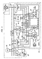
- Figure 1 is a block diagram of a programmable telecommunications switch which may be programmed by a user in accordance with a preferred embodiment of the present invention;
- Figure 2 is diagram which depicts the layers of software used to control the switch of Figure 1;
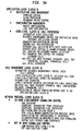
- Figures 3A and 3B depict some of the specific features and functions associated with each of the software layers depicted in Figure 2;
- Figure 4 is a block diagram of a finite state machine development environment constructed in accordance with a preferred embodiment of the present invention;
- Figure 5 is a block diagram illustrating the structure and contents of a generic PPL Event Indication and PPL Event Request message of the present invention;
- Figure 6 is a block diagram of a PPL Event Indication Acknowledgement and PPL Event Request Acknowledgment message of the present invention.
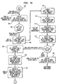
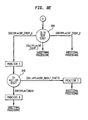
- Figures 7A and 7B are a state diagram of a finite state machine for providing call control processing utilizing the universal API of the present invention to support a highly interactive host telecommunications application requirement;
- Figure 7C is an interface diagram of the universal API supporting the call control processing illustrated in Figures 7A and 7B;
- Figures 7D and 7E are a diagram of the finite state machine of Figures 7A and 7B in which each series of atomic functions is defined as a primitive;
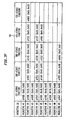
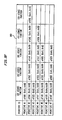
- Figures 7F and 7G are tables showing the correspondence between the atomic functions, primitives and states of Figures 7A-7E;
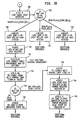
- Figures 8A and 8B are a state diagram of a finite state machine for providing call control processing utilizing the universal API of the present invention to support a limited interactive host telecommunications application requirement;
- Figure 8C is an interface diagram of the host-to-switch API generated by the cal control processing illustrated in Figures 8A and 8B;
- Figures 8D and 8E are a diagram of the finite state machine of Figures 8A and 8B in which each series of atomic functions is defined as a primitive;
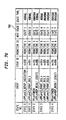
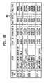
- Figures 8F and 8G are tables showing the correspondence between the atomic functions, primitives and states of Figures 8A-8E;
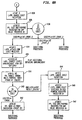
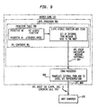
- Figure 9 is a functional block diagram illustrating an exemplary process flow to create a PPL Event Indication message;
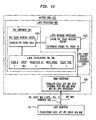
- Figure 10 is a block diagram of the message buffer created by an
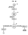
Layer 4 PPL processor during the creation of the PPL Event Indication message of Figure 9; and - Figure 11 is a functional block diagram illustrating an exemplary process flow to create a PPL Event Request message.
-
- Figure 1 shows a commercially available personal computer (PC) 102 which includes a PC central processing unit (CPU) 104 and a
hard disk drive 106 interconnected by a PC input/output (I/O)bus 108 and aPC power bus 109. ThePC 102 is preferably a PC-AT®, sold by International Business Machines (IBM), or a compatible thereof. Other personal computers having more memory or more powerful CPUs than the PC-AT® may also be used. ThePC 102 preferably operates under an application-oriented operating system, such as DOS® or UNIX®. - The
PC 102 consists of a chassis or housing in which a motherboard is mounted, along with thedisk drive 106 and other optional assemblies such as floppy disk drives, modems and the like. ThePC CPU 104 is mounted on the motherboard, which includes a series of edge connectors into which other boards (cards) may be inserted and thereby connected to the PC I/O andpower busses - A
programmable telecommunication switch 110 resides within thePC 102. A CPU/matrix card 112 is inserted into one of the slots on the motherboard and thus connected to thebusses matrix card 112 is interconnected with a digital (T1)line card 114, a digital (E1)line card 115, a digital signal processing (DSP)card 116, apacket engine card 117, an analog (universal) line card 118 and aterminator card 119 by four busses: a high level data link control (HDLC) or interprocessor bus 120; a time division multiplex (TDM)bus 122; a line card (LC) status/control bus 124; and a timing/control bus 126. A battery/ring voltage bus 128 supplies battery voltage (48VDC) and ringing voltage (109VAC) to the analog line card 118. Theterminator card 119 serves to physically terminatebusses - The
line cards DSP card 116 are all connected to and receive their basic operating power from thePC power bus 109. Although only one digital (T1)line card 114, one digital (E1)line card 115 and one analog line card 118 are depicted, it should be understood that additional line cards of any type may be added subject to two physical limitations: (1) the maximum switching capacity of the CPU/matrix card 112, and (2) the physical space within the chassis of thePC 102. - An
external host 130, which may comprise a separate personal computer, workstation or other computer, may optionally be connected via acommunication channel 132 to the CPU/matrix card 112. The CPU/matrix card 112 preferably includes a conventional RS-232 compatible interface for connecting thechannel 132. Theexternal host 130 preferably operates under an application-oriented operating system. - If desired, the
switch 110 can reside on a passive backplane (noPC CPU 104 ordisk 106 present) from which its receives electrical power and be controlled by theexternal host 130. For example, the present invention may be implemented in other processing platforms such as the expandable telecommunications switch disclosed in - U.S. patent number 5,544,163 entitled, Expandable Telecommunications System, assigned to the assignee of the present application.
- An external battery/
ring voltage supply 131 is connected via apath 133 to theterminator card 119.Supply 131 may comprise, for example, a commercially available power supply. - With the exception of the digital (E1)
line card 115, theDSP card 116 and thepacket engine card 117, details regarding the construction of the various cards shown in Figure 1 are set forth in U.S. Patent No. 5,321,744, titled Programmable Telecommunications Switch for Personal Computer, assigned to the assignee of the present application .
Digital (E1)line card 115 is preferably constructed using similar hardware to that disclosed forT1 line card 114, except for differences in conventional circuitry which allowline card 115 to terminate E1 spans as opposed to T1 spans. - Details regarding the construction of the
DSP card 116 and thepacket engine card 117 are set forth in U.S. Patent No. 5,349,579, titled Telecommunications Switch With Programmable Communications Services, assigned to the assignee of the present application,. - Figure 2 is a layer model of the software used to control the
programmable switch 110 of Figure 1. The lefthand column of Figure 2 shows seven layers defined in the Open Systems Interconnection (OSI) reference model. The righthand column of Figure 2 shows five layers used to controlswitch 2 and their general correspondence to the OSI model. - Referring now to both Figures 1 and 2, the
Application Layer 5, which corresponds generally with the Application layer of the OSI model, represents application software which typically runs on either thePC CPU 104 or theexternal host 130.Application Layer 5 software may be used to implement any of a number of desired telecommunications services such as toll free (800) service, voice mail, automatic call distribution (ACD), to name but a few.Application Layer 5 may communicate with any other layer of the programmable switch through the application program interface (API) of the present invention. WhenApplication Layer 5 resides onexternal host 130, the API manages communications overcommunication channel 132. WhenApplication Layer 5 resides onPC CPU 104, the API manages call control processing communications over PC I/O bus 108. - Call
Management Layer 4, which corresponds generally with the Presentation, Session and Transport layers of the OSI model, represents software which runs on the CPU/matrix card 12. CallManagement Layer 4 is responsible for performing centralized call processing functions and providing a common interface toApplication Layer 5 regardless of the type or types of network signalling protocols which may be used within theswitch 102. Typically,Call Management Layer 4 performs functions which are required following call setup. - Network Signalling
Protocol Layer 3 corresponds generally with the Network layer of the OSI model. The software represented by Network SignallingProtocol Layer 3 runs either on the CPU/matrix card 112 or on line cards which include their own microprocessors, such asline cards packet engine card 117, and is responsible for in and out-of-band network signalling supervision as well as network protocol level control of incoming and outgoing calls. -
Link Layer 2 corresponds generally with the Data Link layer of the OSI model.Link Layer 2 software runs on the CPU/matrix card 112, the line cards which include their own microprocessors, theDSP card 116 or the packet engine card 117 (each of which includes its own microprocessor) and is responsible for the detection as well as physical transfer of network signalling information across a network or line interface. - Finally, the
Physical Layer 1 corresponds to the Physical layer of the OSI model.Line cards switch 110. - Figures 3A and 3B are a tabular listing of representative features and functions provided by each of the software Layers 2-5 of Figure 2. The present invention may be used as a development tool to develop suitable software to implement any of the features and functions shown in Figures 3A and 3B. Illustrative examples of the use of the present invention in the context of each of Layers 2-5 are set forth in U.S. Patent No. 5,426,694, assigned to the assignee of the present invention.
- Figure 4 is an overall block diagram of a finite state machine development environment, constructed in accordance with a preferred embodiment of the present invention, which enables a customer or user to create and define finite state machines for performing desired telecommunications functions, controlled by one or more applications through the universal API of the present invention. Before considering this Figure in detail, the definitions of certain terms should be addressed.
- As used herein, the term state refers to a number which represents the current "context" for a particular channel or port. In a preferred embodiment of the present invention, there are three types of states defined: normal, internal and blocking. Normal states can be wait states (i.e., a SEIZE ACK state, a condition in which further action is suspended until the occurrence of a particular event) or stable states (i.e., a conversation is taking place). Internal states are used to test conditions and effectively operate as decision branches. Normal and internal states may be specified by a customer or user, in accordance with present invention, to define a finite state machine for performing a desired function. Blocking states are generated automatically by the present invention and are used, on a channel-by-channel basis, in connection with the management of off-board resources.
- An event is a number which identifies a condition which is accepted by a particular state. Data may be associated with an event.
- An atomic function is one which performs an elementary task such as setting a timer. User-specified data may be associated with an atomic function. A primitive is a predetermined sequence of atomic functions which is invoked upon the occurrence of a particular event. Users may create or define primitives from a library of available atomic functions. In a preferred embodiment, each primitive may contain up to 20 atomic functions.
- A state/event table defines the valid events for a particular state and the primitive which is invoked upon the occurrence of each such event. In a preferred embodiment, a state/event table may contain up to 100 states and up to 20 events per state.
- A primitive table defines the primitives which are used by a state/event table. In a preferred embodiment, a primitive table may contain up to 200 primitives.
- A protocol is defined as the association of various types of tables, the least of which is a statelevent table and primitive table, and is identified by a protocol ID (a number).
- An API protocol is defined as the host-to-switch control protocol between host applications and software layers of the switch.
- A program protocol language (PPL) is a programmable environment for managing network signalling protocols and communications services.
- A data block, such as those denoted by
reference numbers data block - In the case of
channel 0, the active state/event table and active primitive table pointers are pointing, as indicated by the phantom lines, to tables which are associated with aresident protocol 0, denoted byreference number 442a. The assigned state/event table and assigned primitive table pointers forchannel 0 are pointing to tables which are associated with a dynamically loaded, customer-definedprotocol 1, denoted byreference number 444a. - Other protocols which are present and available for use are
resident protocols 1...n (442b, 442c) and downloaded, customer-defined protocols n+1...m (444b, 444c). Theresident protocols 442a-442c represent preprogrammed or "standard" protocols, which are typically provided by a manufacturer with a switch. In contrast, the customer-defined protocols n+1...m are created by a customer or user and may be completely "custom" or "proprietary" in nature. - A layer dependent
atomic function library 446 is connected to provide information to astate machine engine 448.State machine engine 448 is also connected to receive the active state/event table pointer and active primitive table pointer from each ofdata blocks 440a-440n. Also, as denoted byreference number 450, utilities are provided for layer dependent environment support. - The function of the
state machine engine 448 is to drive each channel in accordance with its assigned protocol, which is defined by the assigned state/event table and assigned primitive table. Upon the occurrence of a valid event for a normal state, a primitive is invoked in accordance with the entries in the assigned state/event table. Thestate machine engine 448 uses theatomic function library 446 to perform the atomic functions represented by the invoked primitive. - The
state machine engine 448 will drive through any necessary internal states, automatically generating appropriate blocking states, until the channel once again reaches a normal state. At that time, processing by thestate machine engine 448 is complete until the occurrence of another valid event. - Each channel is initially assigned one of the customer-defined protocols or one of the preprogrammed protocols. This is accomplished by the transmission of an API message from the
Application Layer 5 to theCall Management Layer 4, which in turn issues an appropriate message toLayer 3 which may also be configured in accordance with the API of the present invention. The assigned state/event table pointer and assigned primitive table pointer point to the protocol which was last assigned. Thus, a customer may assign a desired one of the available protocols by simply specifying the appropriate pointers in each data block. In this fashion, the present invention advantageously permits the customer to assign, on a channel-by-channel basis, a desired protocol from among multiple protocols resident within a single switch. - Alternatively, or if the customer elects not to assign protocols to some or all of the channels, default values are preferably provided so that each channel always has a valid protocol (e.g., one of the
resident protocols 442a-442c) assigned to it. - The active state/event table and active primitive table pointers, which are provided to the
state machine engine 448, point to the protocol which is currently controlling the channel. - The protocol assigned to a particular channel is not necessarily permanent and may be dynamically changed in real time in response to the occurrence of a specified event, as described in detail in connection with Figure 7. Further, because the atomic functions provided by the
library 446 represent elementary functions, customers or users are advantageously able to implement desired changes in protocols without substantial, or possibly any, changes to the underlying code. In addition, the environment support utilities are provided to simplify protocol development for the customer or user. The utilities provide ready-to-use resource management functions (e.g., timers) which greatly simplify the state machine logic required to implement desired protocols. Different utilities are preferably provided for each software layer since the resources required by each layer may be different. - In accordance with the present invention, call processing control communications between the
Application Layer 5, typically residing onexternal host 130, and the other layers ofswitch 102 illustrated in Figure 2, is conducted through the transfer of generic messages of the universal API of the present invention.
Specifically, in the preferred embodiment of the universal API of the present invention, a single message type, referred to as the PPL Event Request message, is used to transfer all call control processing commands and data from the host application (Layer 5) to the telecommunications switch (all other software layers). Likewise, a single message, referred to as the PPL Event Indication message, is used to transfer all call control processing status and data from the telecommunications switch to the host applications. These generic API messages have optional fields and are the only messages necessary to maintain call processing regardless of the application requirements, network signalling protocol requirements, or features presently existing or to be added to the telecommunications switch. The programmable switch of the present invention enables a user to define and assign a desired applications program interface protocol, either "standard" or custom in nature, for performing various switching functions to accommodate any of the above requirements. - Referring to Figure 5, a PPL Event Request message is sent from the host to the switch to initiate a host event on a PPL component with optional ICB data. The PPL Event Request message is the only call control processing message passed from the host to the switch and, in the preferred embodiment, having the format of
message 500 illustrated in Figure 5. The PPL Event Request message comprises a number of fields and subfields, each of which is described below. - PPL Event Request message includes a
frame byte 502 having a constant value identifying it as the first byte of a frame. -
Message length field 504 contains the length of the particular PPL Event Request message. This is necessary due to the ability of the generic API messages of the present invention to include optional fields, changing the length of the message. Typically the length field value does not include theframe byte 502. - A
message type field 506 contains a constant value identifying the particular message as a PPL Event Request message. The message type field is constant for all PPL Event Request messages. -
Sequence number field 508 is a specific numeric identifier assigned to each PPL Event Request message that is generated by the host application. This value is used to distinguish between different PPL Event Request messages transmitted from the host to the switch. For example, when the host acknowledges the receipt of a PPL Event Request message, it includes the sequence number in its acknowledgement to identify which of the PPL Event Request messages is associated with the status information contained within the acknowledgement. - As noted, every PPL component state machine in a switch is assigned a unique reference number.
PPL component ID 510 is a one word field that identifies which PPL component implemented in the switch is referenced by a particular PPLEvent Request message 500. - There may be multiple instantiations of a PPL component state machine in a switch at any given time. For example, in the preferred embodiment there is an E1 PPL component state machine assigned to each channel. Thus, in the illustrative embodiment wherein a single E1 card supports 256 channels, there may be as many as 256 instantiations of the E1 PPL component state machine, each associated with a distinct channel. In order to selectively provide access to every instantiation of a PPL component, the universal API of the present invention provides the ability to perform multiple levels of addressing. Thus, once the PPL component has been identified in the PPL
component ID field 510, anaddress element field 514 is provided to identify which instantiation(s) of that PPL component state machine is(are) being referenced. As shown in Figure 5, the PPL Event Request message provides the ability to include any number of address element fields 514, and thus may simultaneously communicate with multiple instantiations of a single PPL component state machine. The total number of address element fields 514 included in a PPL Event Request message is provided in addresselement count field 512. - To accommodate the additional levels of addressing noted above,
address element field 514 contains a number of subfields for further identifying which state machine instantiation is to receive the PPL Event Request message. Specifically, an addresselement type field 516 is provided to reference the hierarchial components of the switch that may contain or be associated with the desired state machine instantiation. In the above example of an E1 PPL state machine instantiation, the addresselement type field 516 indicates which span and channel the state machine instantiation is associated with. Anaddress information subfield 520 provides specific addresses for each of the hierarchial components indicated in the addresselement type field 516. - Since the addressing information contained in
field 520 varies in accordance with the type of device addressed, the length of theAE field 514 may vary and thus is provided inlength subfield 518. It is considered to be apparent to one skilled in the relevant art to use other addressing schemes appropriate for a particular PPL component state machine and switch architecture. It should also be noted that, in the above example, a single state machine instantiation exists for each channel since the PPL component state machine is assigned to each channel individually. However, it is considered to be apparent to one skilled in the relevant art that a particular state machine may be configured to manage any number of channels. - The multiple levels of addressing provide the universal API PPL Event Request message with a flexible addressing scheme. This enables a host application, using a single PPL Event Request message, to address a range of state machine instantiations having a common PPL component ID to generate a particular event at all addressed state machines.
- Each PPL event has a unique ID relative to each PPL component. The PPL
event ID field 522 provides the switch with a user-defined PPL event ID that the switch recognizes as being associated with the particular request. The recipient PPL component maps the unique PPL event ID to a PPL event that is unique to that PPL component. - Each PPL Event Request message may also contain one or more data fields in the form of information control blocks (ICB)s. ICBs are defined for each PPL component based upon the software layer and the communications protocol supported by that PPL component. Thus, any signalling information may be passed between the host and switch using the generic, programmable messages of the present invention.
- Also referring to Figure 5, a PPL Event Indication message is sent from the switch to the host by a PPL component to report an event at the ports to the host with optional ICB data. The PPL Event Indication message is the only call control processing message passed from the switch to the host and in the preferred embodiment, has the same format as the PPL Event Request message illustrated in Figure 5. Except as noted below, the fields of the PPL Event Indication message are identical to and perform the same functions as, the analogous fields of the PPL Event Request message discussed above.
- As noted above, there may be multiple instantiations of a PPL component state machine. For the PPL Event Indication message, the address element field(s) indicate which instantiation of a particular state machine is actually invoking the atomic function that generates the PPL event indication message.
- In the PPL Event Indication message, the PPL
event ID field 522 is a specific value representing the occurrence of a specific event in the switch that results in the PPL Event Indication message being sent from the PPL component state machine. As noted, this is managed with an atomic function that is programmed to send the particular PPL Event Indication message in response to the occurrence of a particular event, the PPL Event ID included in the message being programmed by the user. - It is considered to be obvious to one skilled in the relevant art to configure all transfers of information in the switch using the universal API of the present invention, including all layer-to-layer communications. For example, the exemplary communications described in U.S. Patent No. 5,426,694 may be replaced with the universal API messages of the present invention.
- The PPL components can be layer specific, function specific, interface specific, protocol specific, or channel specific. This enables a
host Layer 5 telecommunications application to be as interactive as desired or necessary, accessing each layer of the switch and managing each PPL component regardless of where the component is located. An application can therefore use the universal API interface to manage any PPL component. This provides a consistent and predictable means for managing every PPL component in the switch, regardless of what level of processing is being performed, ranging from, for example, a very detailed signalling analysis, to network signalling, to high-level call routing, to call management connection functions. - In the preferred embodiment of the present invention, the manner in which the data is identified and passed to the host includes the implementation of one or more atomic functions configured to store and retrieve data of a certain type to specific memory locations in conjunction with one or more atomic functions that generate a generic PPL Event Indication providing the host with all previously stored data. However, as one skilled in the art would find apparent, there are numerous ways in which atomic functions may be configured to pass data in the PPL Event Indication message. For example, a separate atomic function may be implemented to transfer specific types of data in a PPL event indication message.
- The short-hand notation for depicting the PPL Event Request and the PPL Event Indication messages is shown in on the bottom of Figure 5.
- Referring to Figure 6, the telecommunications switch responds to the PPL Event Request with a PPL Event Request Response message having the format of message 600. Similarly, the host applications responds to the PPL Event Indication message with a PPL Event Indication Acknowledge message, also having the format illustrated in Figure 6. Generic acknowledgement message 600 includes a
frame byte 602,length byte 604,message type 606, andsequence number 608, all of which perform the same function as the corresponding fields in the PPLEvent Request message 500. In addition, astatus field 610 provides the recipient with message-specific status information. The short-hand notation for depicting the PPL Event Request Acknowledge and the PPL Event Indication Acknowledge messages is shown in Figure 6. - Referring to Figures 7A-8G, two examples of the utilization of the universal API of the present invention to perform interactive voice processing functions are provided below. The first example illustrates a universal API for managing host-to-switch communications when the telecommunications switch is controlled by a highly interactive
host application Layer 5 to perform interactive voice announcements. The second example illustrates a universal API for managing host-to-switch communications when thehost application Layer 5 has limited interaction with the telecommunications switch to perform the same function. These examples illustrate the ability of the universal API to accommodate various applications requirements. - In the following Figures, a state is depicted as a circle, an atomic function is depicted as a rectangular box, and an event is represented by a word abbreviation located along a path leading out of a state. Information shown in parentheses in an atomic function represents arguments or data that are associated with that function. Reference numbers are provided below in parentheses when necessary to avoid confusion with other numeric descriptors.
- Figures 7A-7B illustrate an example of an application of the present invention in
Call Processing Layer 4 with a high level of interaction required by thehost application layer 5. In this example, the present invention is used to implement a protocol for providing host application decisionmaking throughout the performance of an interactive voice response to an incoming call. - The protocol begins with the associated channel (channel 1) in normal state NS0, which is the
IDLE state 702. Upon the occurrence of the event oflayer 3 transmitting to layer 4 a setup message ((50)L4PPLevL3_SETUP_INDICATION)), the atomic function af35 is performed. As noted in its descriptor, theLayer 4 PPL event (L4PPLev) is received from network signalling protocol layer 3 (L3), reporting that it has detected an incoming call (SETUP_INDICATION). Thenumber 50 in the parenthetical preceding the message descriptor is the PPL event ID assigned to that event by theLayer 4 PPL. Thus, whenLayer 4 is notified of an incoming call, represented by a PPL event ID of 50, the PPL component state machine in Figure 7A leavesidle state 702 and performs atomic function af35 (704). - Atomic function af35 (704) operates to notify the host application (Layer 5) of the event, assigning to the event a PPL event ID of 1. The host application interprets this PPL event ID (the number 1) as a notification of an incoming call. Referring to Figure 7C, atomic function 35 (704) generates a PPL
Event Indication message 701 to notify the host of the incoming call. This PPL Event Indication message has the following format:
PPL Event Ind (L4PPL, ch1, 1)
wherein the PPL component ID indicates theLayer 4 PPL component (L4PPL), the instantiation of theLayer 4 PPL component state machine addressed by this message is the instantiation associated with channel 1 (ch1), and the PPL event ID (1) indicates that an incoming message has been received while the PPL component state machine has been in the idle state NS0. - As shown, the arguments associated with atomic function af35 (704) specify a
Layer 4 PPL event ID. Note that more generally, atomic function af35 is a PPL Send Event Indication message atomic function, used whenever a PPL Event Indication message is to be sent to thehost Layer 5, each message having arguments for indicating the unique PPL event ID associated with the occurrence of a different event The host responds with a PPL Event Indication Acknowledgemessage 703 having the general format:
PPL Event Ind Ack (sequence #, status)
wherein the sequence number is the sequence number provided in the PPLEvent Indication message 701, and the status indicates the status of the associated PPL event indication message. For purposes of this and the following examples, the PPL Event Indication Acknowledge messages all indicate that the immediately previous PPL Even Indication message was successfully received. - After the telecommunications switch provides the host with notification of an incoming call utilizing the PPL Event Indication message of the present invention, the
Layer 4 PPL component state machine enters normal state NS1, which is aWAIT state 706, during which theLayer 4 PPL component waits for the host application to respond to the notification. The host sends aLayer 5 PPL Event Request message 705 (see Figure 7C) with an event ID of 1, indicating that it is requesting that the switch proceed with the call received onchannel 1.Message 705 has the following format:
PPL Event Req (L4PPL, ch1, 1)
indicating that the switch is to respond to the incoming call received onchannel 1. A PPL Event Request message having a PPL Event ID of 1 is interpreted by theLayer 4 PPL component state machine as an event. As illustrated in Figure 7A, the receipt of this PPL Event Request message is assigned by theLayer 4 PPL component state machine aLayer 4 unique PPL event ID of 501, indicating that aLayer 5 PPL Event Request (with a PPL Event ID of 1) has occurred. - In response to
PPL event 501, theLayer 4 PPL component state machine performs 5 atomic functions: atomic function af60 (708), atomic function af62 (710), atomic function af140 (712), atomic function af212 (714) and atomic function af50 (716). Atomic function af60 is an atomic function that generates a generic PPL Event Request Acknowledge message in accordance with the present invention. This atomic function af60 may be used whenever a PPL component of the switch is to acknowledge the receipt of a PPL Event Request message. Theargument number 16 represents an acknowledgement status that the PPL Event Request message was successfully received. This atomic function af60 (708) generates the PPL Event Request Acknowledgemessage 707, having the same general format as the PPL Event Indication Acknowledge message described above. The PPL Event Request Acknowledgemessage 707 indicates that the above incoming message has been successfully received. - Atomic functions af62 (710) and atomic function af140 (712), serve, respectively, to send a connect message (to answer the call) to
Layer 3 and to send a message to allocate a DSP resource for interactive digit string collection. Atomic function af212 (714) plays an opening announcement to the caller. As shown, there are two arguments to af212: an announcement ID and an announcement control option. af212 (714) was selected to play an opening announcement. Atomic function af50 (716) is performed to set a timer to wait for a selected period of time for receipt of incoming digits, entered in response to the announcement played by atomic function af212 (714). As shown, the first argument indicates that the multi-purpose timer to be used for performing this function is timer1. The second argument indicates the number of 1000 ms units the timer is to count. Here, the second argument is 10, indicating that timer1 will count for 10 seconds. Thus, atomic function af50 (716) enables timer1 to expire in 10 seconds, during which time theLayer 4 PPL component enters normal state S2, which isWAIT state 718, wherein the PPL state machine waits for a digit to be detected onchannel 1. - If the next PPL event is the expiration of timer1 ((191) PPLevTIMER1) indicating that no digits were received with the 10 second period, atomic function af35 (720) is performed to inform the host that no digits were received. The receipt of a PPLevTIMER1 message is assigned a PPL event ID of 191 by
Layer 4 PPL component. As noted,atomic function 35 generates the PPL Event Indication message of the present invention. Here, however, a PPL Event ID of 4 is included in the PPL Event Indication message, indicating that there has been a failure to detect digits on the selected channel. The format of this PPL Event Indication message is, therefore:
PPL Event Ind (L4PPL, ch1, 4) indicating that no digits have been detected on the channel associated with thechannel 1 instantiation of theLayer 4 PPL component while theLayer 4 PPL component was in thewait state 718. - Since the interface diagram of Figure 7C illustrates the universal API protocol associated with the successful receipt of digits and subsequent processing of the call announcement, this message is not illustrated in Figure 7C. Processing then continues with a series of atomic functions not shown where, under host application control through the implementation of the universal API of the present invention, the telecommunications switch performs various functions in response to the failure to detect digits on
channel 1. - If the next event to occur while the
Layer 4 PPL component state machine is inwait state 718 is the receipt of a message indicating that digits have been detected onchannel 1, ((66)L4PPLevDSP_RESULT_DIGITS), atomic function af47 (722) is performed. The receipt of this message is assigned a unique PPL Event ID of 66. Thus, whenLayer 4 is notified that digits have been received, theLayer 4 PPL component state machine leaves wait state S2 (718) and performs atomic function af47 (722). Atomic function af47 disables the PPL multipurpose timer (timer1) selected by atomic function af50 (716), as indicated in the argument to the atomic function. Atomic function af53 (724) stores the received digits in a selected general purpose register. Here, af53 (724) stores the received digit ingeneral purpose register 1. - In accordance with the present invention, atomic function af36 (726) is an atomic function configured to send a PPL Event Indication message with the contents of a selected general purpose register (argument 2), with a PPL event ID (argument 1). Here, atomic function af36 (726) sends the contents of the general purpose register 1 to the
Layer 5 host application as a PPLEvent Indication message 709 having an Event ID of 2. PPLEvent Indication message 709 has the format
PPL Event Ind (L4PPL, ch1, 2, digit)
wherein L4PPL is the PPL component ID, ch1 is the address element, 2 is the PPL event ID, and "digit" is the received digit. This PPL Event Indication message exemplifies the capability of the universal API of the present invention to transfer data as well as commands utilizing a single generic PPL Event Indication message format. The host responds with a PPL EventIndication Acknowledgement message 711, indicating that the PPLEvent Indication message 709 was successfully received. Atomic function af147 (728) is then performed to cancel digit reception by disconnecting the DTMF receiver fromchannel 1. - The
Layer 4 PPL component state machine then enters state S4 which is aWAIT state 730, wherein theLayer 4 PPL component state machine will wait indefinitely for thehost application Layer 5 to direct theLayer 4 PPL component state machine how to respond to the digit that was received. As shown in Figure 7B, in the exemplary embodiment, the host application may send theLayer 4 PPL component any one of 3 different responses, havingPPL Event ID - If a PPL
Event Request message 713 having a PPL event ID of 4 is received by theLayer 4 PPL component state machine, ((504)PPLevL5_EVENT_REQ_4) theLayer 4 PPL component state machine assigns aLayer 4 uniquePPL event ID 504 to it, indicating thatLayer 5 provided a PPL Event Request message having a PPL event ID of 4. PPLEvent Request message 711 directs theLayer 4 PPL component state machine to play a specific outgoing announcement. The format of PPLEvent Request message 713 is:
PPL Event Req (L4PPL, ch1, 4) wherein the PPL component ID indicates that the message is directed towards theLayer 4 PPL component (L4PPL), the address element indicates thatchannel 1 is the channel by which the communication is occurring (ch1), and the PPL event ID (4) indicates that a specific additional outgoing announcement is to be played on the identified channel. - In response to
PPL event 504,Layer 4 performs 4 atomic functions: atomic function af60 (732), atomic function af140 (734), atomic function af212 (736) and atomic function af50 (738). Atomic function af60 (732) is an atomic function that generates a generic PPL Event Request Acknowledge message in accordance with the present invention. As noted, atomic function af60 is used whenever a PPL component is to acknowledge the receipt of a PPL Event Request message. Theargument number 16 represents an acknowledgement status that the PPL Event Request message was successfully received. This atomic function generates the PPL Event Request Acknowledge message 764, having the general format described above. - Atomic function af140 (734) serves to allocate a DSP resource for interactive digit string collection to
channel 1. Atomic function af212 (736) plays an additional outgoing announcement onchannel 1. An announcement ID of 3 is indicated by the first argument; no options were selected according to the second argument. Atomic function af50 (738) is performed to set timer1 to wait for a 10 seconds for receipt of incoming digits. The PPL component enters state S5 (740) to wait for the incoming digit for the selected period of time. - The performance of atomic function af212 (736) results in the playing of an announcement to the caller. As shown, there are two arguments to af212: the announcement ID and announcement control options. Atomic function af212 (736) was selected to play an outgoing announcement.
- Atomic function af50 (738) is performed to set a timer to wait for a selected period of time for receipt of incoming digits, entered in response to the announcement played by atomic function af212 (736). In accordance with the arguments, atomic function af212 (736) sets timer1 to expire in 10 seconds. During this period, the
Layer 4 PPL component state machine enters state S5, which is aWAIT state 740 wherein the state machine waits for digits to be received. - In this exemplary embodiment, the host may have alternatively responded with either a PPL Event Request having a PPL event ID of 5 or 6 indicating to the
Layer 4 PPL Component to perform other functions not shown. In both cases, the PPL component state machine performs atomic function af60 (731,733, respectively), indicating that the respective PPL Event Request message was successfully received. - If the next event is the expiration of timer1((191 PPLevTIMER1), the protocol again performs an atomic function af35. Atomic function af35 (742) is performed to inform the host that no digits were received within the allotted time. As noted, atomic functions af35 are configured to generate a PPL Event Indication message in accordance with the present invention. Here, a PPL Event ID of 4 is included in the PPL Event Indication message by atomic function af35 (742), indicating that there has been a failure to detect digits on the selected channel. The format of this PPL Event Indication message is:
PPL Event Ind (L4PPL, ch1, 4) indicating that for thechannel 1 instantiation of theLayer 4 PPL Component, no digits were detected within the allotted time. Since the interface diagram of Figure 7C illustrates the API protocol associated with the successful processing of the call announcement sequence, this message is not illustrated in that Figure. - For reasons given above, this is not shown in Figure 7C. Processing then continues with a series of atomic functions not shown where, under host ampliation control through the implementation of the universal API of the present invention, the telecommunications switch performs various functions in response to the failure to detect digits on
channel 1. - If the next event to occur while the
Layer 4 PPL component state machine is in wait fordigit state 740, is the receipt of a message indicating that digits have been detected onchannel 1, ((66)L4PPLevDSP_RESULT_DIGITS), atomic functions af47 (744), af53 (746) and af36(748) are performed to disable the PPL multipurpose timer (timer1) previously selected, storing the received digits in a selected general purpose register, and sending a PPLEvent Indication Message 717, respectively. - In accordance with the present invention atomic function af36 (748) is an atomic function configured to send a PPL Event Indication message with the contents of general purpose register 1 with a PPL event ID of 3. Here, atomic function af36 (748) sends the contents of the general purpose register 1 to the
Layer 5 host application as a PPLEvent Indication message 717 having an Event ID of 3. PPLEvent Indication message 717 has the format:
PPL Event Ind (L4PPL, ch1, 3, digit)
wherein L4PPL is the PPL component ID, ch1 is the address element, 3 is the PPL event ID, and "digit" is the received digit. This event ID indicates that the returned digit is in response to an af212 atomic function playing an outgoing announcement having at announcement ID of 3. The host responds with a PPL EventIndication Acknowledgement message 719, indicating that the PPLEvent Indication message 711 was successfully received. - Referring now to Figures 7D and 7E, it may be seen that each sequence of atomic functions shown in Figures 7A-7B has been defined as a primitive. In effect, each primitive provides a shorthand way to identify a desired sequence of atomic functions to invoke. The table of Figure 7F lists in tabular format the sequence of atomic functions for each primitive.
- Figure 7G is a state/event table that defines the relationships between the states, events and primitives of Figures 7D and 7E. In accordance with a preferred embodiment of the present invention, a customer wishing to create the protocol depicted in Figures 7A-7B, would need only define the tables shown in Figure 7F and 7G Those tables would then be downloaded to the switch 102 (Figure 1) through a series of messages from the host device.
- Referring to Figures 8A-8G, a second example of the universal API of the present invention configured to manage host-to-switch communications is illustrated. IN this example, the
host application Layer 5 has limited interaction with the telecommunications switch while performing these functions. Specifically, the telecommunications switch is configured to automatically respond to the digits that are entered. In contrast to the previous example, theLayer 4 PPL state machine includes internal states responsive to prompts internally generated during digit collection.
These aspects of the switch replace the atomic functions generating PPL Event Indication messages to the host providing the received digit, and the subsequent wait states wherein the switch waits for the host to supply it with a PL Event Request message. - Figures 8A-8B illustrate an example of an application of the present invention in
Call Processing Layer 4 with a limited level of interaction required by thehost application Layer 5 to implement a protocol for providing limited host application decisionmaking in the performance of an interactive voice response to an incoming call. - The protocol begins with the associated channel (channel 1) in normal state S0, which is the
IDLE state 702. Upon the occurrence of the event oflayer 3 transmitting to layer 4 a setup message ((50)L4PPLevL3_SETUP_INDICATION)), the PPL component state machine in Figure 8A leaves,idle state 802 and performs atomic function af35 (804). - Atomic function af35 (804) operates to notify the host application (Layer 5) of the event, assigning to the event a PPL event ID of 1. The host application interprets this PPL event ID value of 1 as a notification of an incoming call. Referring to Figure 8C, atomic function 35 (804) generates a PPL
Event Indication message 801 to notify the host of the incoming call. This PPL Event Indication message has the same format as PPLEvent Indication message 701, and indicates that thechannel 1 instantiation of theLayer 4 PPL component state machine addressed by this message received an incoming message while theLayer 4 PPL component state machine was in the idle state. - The host responds with a PPL Event Indication Acknowledge
message 702 having the general format described above, indicating that the previous PL Event Indication message was successfully received. - After the telecommunications switch provides the host with notification of an incoming call utilizing the PPL Event Indication message of the present invention, the
Layer 4 PPL component state machine enters normal state S1, which is theWAIT state 706, during which theLayer 4 PPL component waits for the host application to respond to the notification. The host sends aLayer 5 PPLEvent Request message 705 with an event ID of 1, indicating that it is requesting that the switch proceed with the call received onchannel 1. This message has the format described above, indicating that an incoming message has been received onchannel 1 for that instantiation of theLayer 4 PPL component while theLayer 4 PPL component state machine has been in the idle state. - The receipt of this PPL Event Request message is identified by the
Layer 4 PPL component state machine as a PPL event and is assigned aLayer 4 unique PPL event ID of 501, indicating that aLayer 5 PPL Event Request (1) has occurred. - In response to
PPL event 501, theLayer 4 PPL component state machine performs 5 atomic functions: atomic function af60 (808), atomic function af62 (810), atomic function af140 (812), atomic function af212 (814) and atomic function af50 (816). As noted, atomic function af60 is used whenever a PPL component is to acknowledge the receipt of a PPL Event Request message. Theargument number 16 represents an acknowledgement status that the PPL Event Request message was successfully received. This atomic function af60 (808) generates the PPL Event Request Acknowledgemessage 807, having the same general format as the PPL Event Indication Acknowledge message described above. The PPL Event Request Acknowledgemessage 807 indicates that the above incoming message has been successfully received. - Atomic functions af62 (810), af140 (812), af212 (814) and af50 (816) perform the same function as the analogous atomic functions described above with reference to Figure 7A. Atomic function af50 (816) enables timer1 to expire during which time the
Layer 4 PPL component enters normal state S2, which isWAIT state 818, wherein the PPL state machine waits for a digit to be detected onchannel 1. - As in the above example, if the next PPL event is the expiration of timer1 ((191) PPLevTIMER1) indicating that no digits were received within the selected waiting period, atomic function af25 (820) is performed.
- If the next event to occur while the
Layer 4 PPL component state machine is inwait state 818 is the receipt of a message indicating that digits have been detected onchannel 1, ((66)L4PPLevDSP_RESULT_DIGITS), atomic functions af47 (822), af53 (824), and at 147 (828) are performed. These atomic functions performs similar functions to the analogous atomic functions described above with reference to Figures 7A and 7B. Note that an atomic function analogous to af36 (726) is not invoked. Thus, the received digit is not provided to the host application. - Atomic function af28 (829) is performed to test the value of the digit stored in the general purpose register used in atomic function af63 (824) to store the received digit. The
Layer 4 PPL component state machine enters internal state IS3 which is aTEST state 830, wherein theLayer 4 PPL component state machine tests the value of the digit that was received and stored ingeneral purpose register 1. As shown in Figure 7B, in the exemplary embodiment, the tested digit may have any one of 3 different values, each generating an internal event havingPPL Event ID - If a PPL Internal Event message having a PPL event ID of 0 ((200)PPLevINT_EVENT_0) is provided to the
Layer 4 PPL component state machine, theLayer 4 PPL component state machine assigns aLayer 4 uniquePPL event ID 200 to it to indicate that the internal event having a PPL event ID of 0 was received. - In response to
PPL event 200, theLayer 4 PPL component state machine performs 3 atomic functions af140 (834), af212 (836) and atomic function af50 (838), each of which perform functions similar to the analogous atomic functions described above with reference to Figures 7A and 7B. Note that an atomic function analogous to af60 (732) is not performed since the switch tests the incoming digit itself, and does not wait for a host generated PPL Event Request message. Therefore, no acknowledgement is required to be generated. - The
Layer 4 PPL component state machine then enters normal state NS4, which is aWAIT state 840 wherein the state machine again waits for digits to be received. - If no digits are received, the next event is the expiration of timer1((191) PPLevTIMER1), the protocol performs an atomic function af35 (842) to inform the host that no digits were received within the allotted time. Processing then continues with a series of atomic functions not shown where, under host ampliation control through the implementation of the universal API of the present invention, the telecommunications switch performs various functions in response to the failure to detect digits on
channel 1. - If the next event to occur while the
Layer 4 PPL component state machine is in wait fordigit state 840, is the receipt of a message indicating that digits have been detected onchannel 1, ((66)L4PPLevDSP_RESULT_DIGITS), atomic functions af47 (844), af53 (846) are performed. These atomic functions perform similar functions to the analogous atomic functions described above with reference to Figures 7A and 7B. Further, atomic function af28 (847) is performed to test the value of the now second received digit stored ingeneral purpose register 1. A function analogous to atomic function af36 (748) is not performed, thereby not providing the host with a PPL Event Indication message. - Referring now to Figure 8D-8E, it may be seen that the each sequence of atomic functions shown in Figures 8A-8B has been defined as a primitive. In effect, each primitive provides a shorthand way to identify a desired sequence of atomic functions to invoke. The table of Figure 8F lists in tabular format the sequence of atomic functions for each primitive.
- Figure 8G is a state/event table that defines the relationships between the states, events and primitives of Figure 8D and 8E. In accordance with a preferred embodiment of the present invention, a customer wishing to create the protocol depicted in Figures 8A-8B, would need only define the tables shown in Figure 8D and 8E. Those tables would then be downloaded to the switch 102 (Figure 1) through a series of messages from the host device.
- Referring to Figures 9-11, a
Layer 4PPL component 901 is executed as part of aLayer 4PPL processor 902. As noted above, there may be multiple instantiations of a PPL component operating simultaneously, each of which has an associated state machine and tables. All instantiations of a theLayer 4PPL component 901 are executed on a PPLstate machine engine 1104.Layer 4PPL processor 902 also includes aLayer 4PPL message processor 1102 for receiving and processing internal PPLEvent Request messages 1106. Each PPL processor such asLayer 4PPL processor 902 may contain any number of PPL components. In the exemplary embodiment shown in Figures 9 and 11, theLayer 4PPL processor 902 contains asingle Layer 4PPL component 901. - Figure 9 illustrates the process flow related to the invocation and execution of an atomic function to create a PPL Event Indication message. For exemplary purposes, Figure 9 illustrates the functions preformed in relation to the processing of atomic function af35 (704) of primitive #1 (750) to create PPL
Event Indication message 701. Atomic function af35 (704) is part of theLayer 4PPL component 901. -
Layer 4PPL processor 902 resides on CPU/matrix card 112 in the illustrative embodiment discussed above, and invokes atomic functions in accordance with the state/event and primitive tables to perform various functions, including the functions discussed above with reference to theCall Management Layer 4 in Figure 2. As noted,Call Management Layer 4 is responsible for performing centralized call processing functions and providing a common interface toApplication Layer 5. - In the preferred embodiment of the present invention, the functions performed by the
Layer 4PPL processor 902 are implemented in a publicly available, proprietary operating system referred to as PSOS, available from Integrated Systems, Inc., Santa Clara, California, USA. However, as will become apparent to one skilled in the relevant art, the present invention may be implemented in any commonly known software program and in any software language now or later developed. - Generally, the
Layer 4PPL processor 902 invokes atomic functions that generate internal representations of the PPL Event Indication message. The internal message is passed to acommunications processor 906, also residing on the CPU/matrix card 112, for translation into a PPL Event Indication message of the universal API of the present invention. - When
Layer 4PPL processor 902 executes a primitive of a PPL component state machine, it invokes each of the atomic functions associated with that primitive, as indicated by the primitive table 780 discussed above. In the example discussed above with reference to Figures 7A and 7B, atomic function af35 (704) is the only atomic function included in primitive #1 (750). As noted,atomic function 35 is a PPL Send Event Indication atomic function used whenever a PPL Event Indication is to be sent to the host, each occurrence of the atomic function having a different PPL event ID to indicate the occurrence of a different event. - A number of functions, each of which is described below, are performed by the
Layer 4 PPL atomic function af35 (704) to create the PPLEvent Indication message 701 for transmission to aLayer 5 host application. Referring to Figure 10,layer 4PPL processor 902 allocates amessage buffer 1050 to "attach" to the internal representation of the PPLEvent Indication message 904 generated by the atomic function af35 (704). The message buffer is used by the PSOS operating system to store the necessary information for creation of the PPLEvent Indication message 701. A pointer to that message buffer is obtained through the PSOS operating system when the buffer is allocated. - Once the message buffer is allocated, destination and
source ID fields Layer 5 applications residing on the host, the universal API of the present invention may be implemented to manage communications between any two instantiations of any PPL components residing in the same or different PPL processors. - When the universal API is utilized to achieve communications between PPL components that are located in, or "owned", by the same PPL processor, then the source and destination ID fields are loaded with the PPL component ID. Otherwise, the source and destination ID fields are loaded with the processor virtual ID, and the
message type field 1058 is used by the destination PPL component or application to direct the message to the appropriate instantiation of the desired PPL component residing in the destination PPL processor. Themessage type field 1058 contains a unique message type identifier that is associated with a specific PPL component. - The
Layer 4PPL processor 902 also loads a PPL event ID into the associatedfield 1056 of the message buffer, the event ID identified in the PPL primitive table 780 provided to atomic function af35 (704). In the example illustrated in Figure 7, atomic function af35 (704) indicates the detection of an incoming call during idle state S0, and is assigned a PPL event ID of 1. - An
ICB count field 1062 is loaded with the number of trailing ICB data fields 1064, if any. - The
Layer 4PPL processor 902 transfers thedata buffer 1050 to the PPLEvent Indication message 904. This is accomplished by invoking a function that attaches the allocatedbuffer 1050 to the PPLEvent Indication message 904 by providing thecommunications processor 906 with a pointer to thedata buffer 1050. Thecommunications processor 906 reformats the API messages of the present invention from the internal representation usable by thePPL processor 902 to the format shown in Figure 5 for transmission to the host application.Communications processor 906 performs well known translating operations typical of message handling communications processors, and is considered to be well known in the art.Communications processor 906 then transmits the PPLEvent Indication message 701 to an applications program located inhost computer 130 via theAPI interface 908. - The scheme discussed above with respect to the
Layer 4PPL processor 902 is shown below by the following pseudo-code. It is envisioned that this pseudo-code can be used to generate source code for the present invention in any suitable language, such as C, C++ or PASCAL: - 1. allocate psos msg data buffer (ppl_data_buff);
- 2. psos_msg.ppl_component=L4PPL;
- 3. psos_msg.event_id=event_id;
- 4. psos_msg.destination = HOST;
- 5. psos_msg.source = L4PPL;
- 6. psos_msg.timeslot_addr =
CHANNEL 1; - 7. 14ppl_send_msg (psos_msg, comm queue);
-
- Figure 11 illustrates the process flow related to the receipt and processing of a PPL Event Request message. For exemplary purposes, Figure 11 illustrates the functions related to the processing of PPL
Event Request message 705 received at wait state S1 (706), invoking primitive 2 atomic functions as shown in primitive table 780. - The
communications processor 906 performs the inverse operation of that performed above with respect to the PPL Event Indication message. That is, thecommunications processor 906 / receives the API version of the PPLEvent Request message 705 overAPI 908 and translates it into an internal PSOS PPLEvent Request message 1106.Communications processor 906 transmits the PPLEvent Request message 1106 to theLayer 4PPL processor 902. ALayer 4PPL message processor 1102 receives and processes the internal PPLEvent Request message 1106 and generates adistinct Layer 4 PPL event for theLayer 4 PPLstate machine engine 1104. - The
Layer 4PPL message processor 1102 converts thePPL event ID 522 ofmessage 705 into aLayer 4 unique PPL event ID for theLayer 4PPL state machine 1104 by adding alayer 5 event request base value of 500 to the PPL event ID. Thus, in the exemplary embodiment, theLayer 4PPL message processor 1102 adds a base value of 500 to the PPL Event Request message PPL event ID of 1 to result in aLayer 4 unique PPL event ID of 501. - Once the PPL Event Request message is mapped to a
Layer 4 unique PPL event ID, a pointer is derived to the selected channel's PPL data based upon the address element value in the message that contained a logical span and channel ID. In other words, theLayer 4PPL message processor 1102 converts the logical address into a physical address, i.e.., a physical time slot inswitch 102. Then the PPL state machine engine is invoked, typically as a function call, with the channel pointer for the PPL component instantiation data block and a pointer to the data block associated with the PPLEvent Request message 1106 that was received from thecommunications processor 906. - The
Layer 4 PPL componentstate machine engine 1104 processes theLayer 4 unique PPL event ID, searching the state/event table 790 for that PPL Event ID for the present state. If a matching event is found, thestate machine engine 1104 invokes the identified primitive in the state/event table, retrieving from primitive table 780 the atomic functions associated with the primitive ID. - Thus, in the illustrative embodiment, the
Layer 4 PPL componentstate machine engine 1104 processesPPL event 501, locating the PPL Event ID of 501 for the present state S1 (706) in the state/event table 790 and invoking the atomic functions associated withprimitive # 2. The PPLstate machine engine 1104 enters the state indicated in theLayer 4 PPL state/event table 790 after processing all the atomic functions associated with primitive 2. - Pseudo-code for
Layer 4PPL message processor 1102 as contemplated by embodiments of the present invention is disclosed below: - 1. ppl_event=psos_msg.ppl_data_buff®ppl_event + ppl_L5_event_req_base
- 2. ppl_chan_ptr = ppl_data [psos_msg.hdr.timeslot_addr]
- 3. ppl_stmch(ppl_chan_ptr, ppl_event, psos.msg)
-
- It should be understood that embodiments of the present invention can be implemented in hardware, software or a combination thereof. In such embodiments, the various components and steps would be implemented in hardware and/or software to perform the functions of the present invention. Any presently available or future developed computer software language and/or hardware components can be employed in such embodiments of the present invention. In particular, the pseudo-code discussed above can be especially useful for creating the software embodiments.
- While the invention has been particularly shown and described with reference to preferred embodiments thereof, it will be understood by those skilled in the art that various changes in form and details may be made therein without departing from the scope of the invention. Furthermore, the terms and expressions which have been employed are used as terms of description and not of limitation, and there is no intention, in the use of such terms and expressions, of excluding any equivalents of the features shown and described or portions thereof, but it is recognized that various modifications are possible within the scope of the invention claimed.
Claims (49)
- A functionally-layered programmable telecommunication switch (110) comprising:characterised by further comprisingcontrollable-switching means (115-118) for dynamically connecting or disconnecting communication paths between various ones of a plurality of channels in response to messages generated by a telecommunications services application;
one or more instantiations of a plurality of programmable protocol language (PPL) component state machines (448), each of which is associated with a PPL component of said telecommunications switch and each of which represents one of a plurality of protocols configured to perform call processing functions with respect to said plurality of channels, wherein said plurality of PPL component state machines are functionally associated with the functional layers of the telecommunications switch including said PPL components; and
a programmable universal applications program interface (API) for transferring standardized messages between said functional layers and between said functional layers and said telecommunications services application. - The telecommunications switch in claim 1, wherein said functional layers of said telecommunication switch comprise:an application layer comprising said telecommunications service applications configured to operate in conjunction with one or more of said functional layers to perform telecommunications service functions.
- The telecommunications switch of claim 2, wherein said application layer resides in said telecommunications switch and further wherein said universal API defines communications that occur over a bus internal to said telecommunications switch.
- The telecommunications switch of claim 2, wherein said functional layers further include an application layer residing in a host computer system (130) coupled to said telecommunications switch, and wherein said API is adapted to define communications that occur over a communication channel (132) coupling said telecommunications switch and said host device.
- The telecommunications switch of claim 2, wherein said telecommunications services provided by said telecommunication service application includes at least one of toll-free service functions,
voice mail service functions, and
automatic call distribution service functions. - The telecommunications switch of claim 2, wherein said call processing function performed by said telecommunication service application includes interactive voice response functions.
- The telecommunications switch of claim 2, wherein said call processing function performed by said telecommunication service application includes at least one of
personal communications services functions,
tone generation functions,
call conferencing functions,
call management functions,
call progress tone control functions, and
inbound call routing and queuing functions. - The telecommunications switch of claim 1, wherein said functional layers comprise:a call management layer for performing centralized call processing functions.
- The telecommunications switch of claim 8, wherein said centralized call processing functions performed by said call management layer includes at least one of the following:recorded announcement control functions for interactive voice response application support;reconnection and transfer functions;the provision of multiple call management features; andconferencing connection management functions.
- The telecommunication switch of claim 1, wherein said functional layers comprise:a network signalling protocol layer for performing network signalling functions.
- The telecommunications switch of claim 10, wherein said network signalling functions performed by said network signalling protocol layer includes at least one of the following:in- and out-of-band network signalling supervision; andnetwork protocol level control of incoming and outgoing calls.
- The telecommunications switch of claim 1, wherein said functional layers comprise:a link layer for detecting and transferring network signalling information across a network or line interface.
- The telecommunications switch of claim 12, wherein said link layer runs on a CPU/matrix card (112), or line cards (114, 115, 118).
- The telecommunications switch of claim 12, wherein said functions performed by said link layer include at least one of the following:T1 robbed bit signal scanning;E1 channel associated signalling scanning;T1/E1 line interface frame alarm control;DSP tone generation control; andDSP recorded voice announcement control.
- The telecommunications switch of claim 1, wherein said functional layers comprise:a physical layer implemented in line cards (114, 115, 118) being adapted to provide physical and electrical network and line interfaces to the switch.
- The telecommunications switch of claim 1, wherein said API comprises:predetermined message formats for all messages transferring call control processing commands, status and data between said functional layers.
- The telecommunications switch of claim 1, wherein each said one or more PPL component state machines (448) comprises,
one or more libraries each containing one or more predetermined functions;
one or more predetermined logical states;
at least one predetermined event associated with each said one or more predetermined logical states, each said at least one predetermined event uniquely identified relative to each said one or more PPL component state machines; and
wherein upon an occurrence of one of said one or more predetermined events, a predetermined primitive associated with the occurring event is invoked, said predetermined primitive comprising a predetermined series of one or more said predetermined functions. - The telecommunications switch of claim 17, wherein
said switch further comprises one or more state machine engines (448), and wherein each said one or more component state machines comprises one or more libraries of predetermined fimctions,
wherein each said one or more component state machines is configured to be interpreted by one or more state machine engines. - The telecommunications switch of claim 17, wherein each of said one or more state machines is defined by a functional combination of a state/event table and a primitive table, wherein
said state/event table defines one or more predetermined logical states and at least one of said one or more predetermined events associated with each said one or more predetermined logical states, and wherein
said primitive table defines one or more primitives each of which comprises a predetermined series of one or more said predetermined functions. - The telecommunications switch of claim 17, wherein
said switch further comprises one or more state machine engines, and wherein each said one or more finite state machines is configured to be interpreted by one or more state machine engines. - The telecommunication switch of claim 17, wherein said standardised messages include a PPL event request message (500), for transferring all call control processing commands and data from a host device to said telecommunications switch.
- The telecommunications switch of claim 21, wherein said PPL event request message comprises:a PPL component ID for identifying which of said one or more PPL component state machines is referenced by a particular PPL event request message;one or more address element fields, each identifying one of said one or more instantiations of said PPL component state machine identified in said PPL component ID field; anda PPL event ID field containing a user-defined event ID representing an associated event unique to a particular PPL component state machine identified in said PPL component ID field.
- The telecommunications switch of claim 22, wherein each said one or more address element fields comprises:an address element type subfield for referencing components of said switch associated with said state machine instantiation identified in said one or more address element fields; andan address information subfield adapted to provide specific addresses for each of the hierarchical components indicated in said address element type field.
- The telecommunications switch of claim 22, wherein said PPL event request message further comprises:one or more data fields associated with each of said one or more PPL component state machines, for transferring call control processing information to said switch from a host (130) which, in use, is connected to said switch in communicating relationship.
- The telecommunications switch of claim 19, wherein said standardised messages include a PPL event indication message (500) for transferring all call control processing status and data from said telecommunications switch to said host device, and wherein said PPL event indication message (510) comprises:a PPL component ID field (510) for identifying which of said one or more PPL component state machines is referenced by a particular PPL event indication message;one or more address element fields (512, 514) each identifying one of said one or more instantiations of said PPL component state machine for invoking the function that generates said PPL event indication message; anda PPL event ID field (522) containing a user-defined event ID representing the occurrence of a specific event in said switch that results in a particular PPL event indication message being generated by said PPL component state machine.
- The telecommunications switch of claim 25, wherein said PPL event indication message (500) is generated by one of said one or more functions configured to send the particular PPL event indication message in response to the occurrence of a particular event, and wherein each said one or more address element fields comprises:an address element type subfield (516) for referencing components of said switch associated with said state machine instantiation identified in said one or more address element fields; andan address information subfield (520) adapted to provide specific addresses for each of the hierarchical components indicated in said address element type field.
- The telecommunications switch of claim 25, wherein said PPL event indication message further comprises:one or more data fields associated with each of said plurality PPL component state machines, for transferring call control processing information between said functional layers, said data blocks defined for each said plurality of PPL components based upon which of said functional layers said PPL component state machine is associated with and the communications protocol supported by the PPL component state machine.
- A functionally-layered programmable telecommunication switch characterised by comprising:wherein said one or more predetermined functions includes generating a first application program interface (API) message having a first predetermined message format for all messages transferring call control processing information from said state machine; anda layer-specific processor having a state machine engine (448) configured to execute an instantiation of a PPL component state machine representing a call processing protocol associated with a communications channel in the switch, said state machine being adapted to invoke one or more predetermined functions in accordance with a current state and the occurrence of a predetermined event,
wherein said predetermined event is one of a plurality of events including the receipt of a second API message having a second predetermined message format for all messages transferring call control processing to said state machine. - The switch of claim 28, wherein said layer-specific processor is configured to process said first and second API message in an internally-represented form, and
wherein said switch further comprises:a communications processor, coupled to said layer-specific processor, configured to convert between internally-represented API message form and said universal standardized API message form, and further configured to transmit said first universal API message. - The switch of claim 28, wherein said processor comprises:an atomic function message buffer including a destination identification field and a source identification field containing respective addresses of a source and receiving PPL component instantiation residing in the same or different PPL processors; andmeans for attaching said message buffer to said internal representation of said PPL event indication message generated by said atomic function.
- The switch of claim 30, wherein said message buffer further comprises:a PPL event identification field identifying the event that generated said atomic function.
- The switch of claim 30, wherein said message buffer further comprises:one or more data fields containing information associated with said event and said atomic function for a receiving instantiation.
- The switch of claim 28, wherein said plurality of PPL component state machines are one of the following:layer specific;function specific; andprotocol specific.
- A telecommunications system, comprising:a host device (130); anda programmable telecommunications switch (110);according to any one of the preceding claims.
- A universal applications program interface (API) for standardized interactive call processing communications between functional layers of a telecommunications system including a telecommunications switch (110) and a host device (130) coupled to the switch, characterised by comprising:means for generating a first programmable message for transferring all call control processing commands and data from said host to said functional layers of said telecommunications switch; andmeans for generating a second programmable message for transferring all call control processing status and data from said functional layers of said telecommunications switch to said host.
- A system incorporating the API of claim 35 and a telecommunications switch characterized in that the telecommunications switch comprises:wherein upon an occurrence of one of said one or more predetermined events, a predetermined primitive associated with the occurring event is invoked, said primitive comprising a predetermined series of one or more said predetermined functions,one or more instantiations of one or more PPL component state machines each of which represents a call processing protocol, each said one or more finite state machines comprising,one or more libraries each containing one or more predetermined functions;one or more predetermined logical states;at least one predetermined event associated with each said one or more predetermined logical states, each said at least one predetermined event uniquely identified relative to each said one or more PPL component state machines; and
wherein said one or more predetermined events includes receipt of said first programmable message and wherein at least one of said one or more predetermined functions is adapted for generating said second programmable message. - The system of claim 36, wherein
said telecommunications switch further comprises one or more state machine engines, and wherein
each said one or more PPL component state machines comprises one or more libraries of said one or more predetermined functions, and wherein
each said one or more PPL component state machines is configured to be interpreted by said one or more state machines engines. - The system of claim 36, wherein said API further comprises:wherein a host device is adapted to transmit said acknowledge message to said telecommunications switch upon receipt of said first programmable message andmeans for generating an acknowledge message including a status field providing the recipient with message-specific status information, and
wherein at least one of said one or more predetermined functions is configured to transmit said acknowledge message to said host device upon receipt of said second programmable message. - A method for developing call-associated protocols for performing call processing functions related to communication paths established between various ones of a plurality of channels in a programmable telecommunications switch, said call processing function associated with the functions performed by a particular functional layer of said switch, characterised by the method comprising the steps of:(a) creating one or more state/event tables each of which defines,
a plurality of predetermined logical states,
one or more predetermined events associated with each of said plurality of predetermined logical states, said one or more predetermined events including receipt of one or more application program interface (API) messages generated at the same or different functional layer as said created call-associated protocol, and
a primitive associated with each said one or more predetermined events, wherein said primitive is invoked upon an occurrence of said one or more associated events;(b) creating one or more primitive tables each of which defines a predetermined series of predetermined layer-dependent functions for each said primitive, one or more of said predetermined functions generating an API message to said functional layer; and(c) creating one or more protocols each of which is represented by a predetermined association of one or more of said state/event tables and one or more of said one or more primitive tables. - The method of claim 39, further comprising the steps of:(d) storing said one or more call-associated protocols within said programmable telecommunications switch; and(e) executing said one or more call-associated protocols within said telecommunications switch.
- The method as in claim 39, wherein each of said one or more protocols is represented by a finite state machine having access to a library containing definitions of said predetermined functions, and configured to be interpreted by a state machine engine, said state machine engine operating in response to a pointer to one of said state/event tables.
- A method for communicating between two layers of a functionally-layered programmable telecommunication switch system utilizing a standardized universal application program interface (API), characterised by the method comprising the steps of:(1) invoking one or more instantiations of a layer-specific program protocol language (PPL) component state machine at a layer-specific PPL processor having a state machine engine, each of said one or more instantiations representing a call processing protocol;(2) invoking atomic functions in accordance with state/event and primitive tables defining said state machine and stored in the processor to perform various functions, said atomic functions generating internal representations of a API event indication message; and(3) transferring said internally-represented PPL event indication message to a communications processor coupled to said processor for translation into a universal standardized PPL event indication message.
- The method of claim 42, further comprising the step of:(4) transmitting said universal API message to another PPL component state machine instantiation residing in the same or different PPL processor.
- The method of claim 42, wherein the method further comprises the step of (4) transmitting said universal API message to an application located on a host.
- The method of claim 43, further comprising the steps of:(5) creating an atomic function message buffer, by said processor, including a destination identified field and a source identification field containing respective addresses of said source and receiving PPL component instantiation; and(6) attaching said message buffer to said internal representation of said PPL event indication message generated by said atomic function.
- The method of claim 45, wherein said message buffer further comprises:a PPL event identification field identifying the event that generated said atomic function.
- The method of claim 45, wherein said message buffer further comprises:one or more data fields containing information associated with said event and said atomic function for receiving instantiation.
- The method of claim 42, further comprising the steps of:(4) receiving at said communications processor, a universal API PPL event request message;(5) translating at said communications processor, said universal API PPL event request message into an internally-represented PPL event request message;(6) transmitting said internally-represented PPL event request message to said layer-specific PPL processor;(7) receiving and processing, at said layer-specific PPL processor, said internally-represented PPL event request message; and(8) converting a PPL event ID value included in said internally-represented PPL event request message into a layer-specific unique PPL event identification value for said layer-specific state machine; and(9) processing the layer-unique PPL event identification value by said layer-specific PPL component state machine engine.
- The method of claim 48, wherein said step (9) comprises the steps of:(a) searching said state/event table for that PPL event identification value for the present state of said state machine;(b) when a matching event is found, invoking the identified primitive in the state/event table, retrieving from primitive table the atomic functions associated with the primitive ID;(c) invoking an identified primitive in the state/event table; and(d) retrieving from primitive table the atomic functions associated with the primitive ID.
Applications Claiming Priority (3)
| Application Number | Priority Date | Filing Date | Title |
|---|---|---|---|
| US08/566,414 US5826030A (en) | 1995-11-30 | 1995-11-30 | Telecommunication switch having a universal API with a single call processing message including user-definable data and response message each having a generic format |
| US566414 | 1995-11-30 | ||
| PCT/US1996/018959 WO1997020439A1 (en) | 1995-11-30 | 1996-11-27 | Telecommunications switch having a universal applications program interface for stantardized interactive call processing communications |
Publications (2)
| Publication Number | Publication Date |
|---|---|
| EP0807358A1 EP0807358A1 (en) | 1997-11-19 |
| EP0807358B1 true EP0807358B1 (en) | 2002-09-25 |
Family
ID=24262788
Family Applications (1)
| Application Number | Title | Priority Date | Filing Date |
|---|---|---|---|
| EP96940891A Expired - Lifetime EP0807358B1 (en) | 1995-11-30 | 1996-11-27 | Telecommunications switch having a universal applications program interface for stantardized interactive call processing communications |
Country Status (11)
| Country | Link |
|---|---|
| US (4) | US5826030A (en) |
| EP (1) | EP0807358B1 (en) |
| JP (1) | JPH10513633A (en) |
| KR (1) | KR19980701797A (en) |
| AT (1) | ATE225110T1 (en) |
| AU (1) | AU718827B2 (en) |
| BR (1) | BR9606820A (en) |
| CA (1) | CA2211780C (en) |
| DE (1) | DE69623931T2 (en) |
| IL (1) | IL121434A (en) |
| WO (1) | WO1997020439A1 (en) |
Families Citing this family (78)
| Publication number | Priority date | Publication date | Assignee | Title |
|---|---|---|---|---|
| US5793954A (en) * | 1995-12-20 | 1998-08-11 | Nb Networks | System and method for general purpose network analysis |
| US6493761B1 (en) * | 1995-12-20 | 2002-12-10 | Nb Networks | Systems and methods for data processing using a protocol parsing engine |
| US6651102B2 (en) * | 1995-12-20 | 2003-11-18 | Nb Networks | Systems and methods for general purpose data modification |
| IL119914A (en) | 1996-12-25 | 2000-06-29 | Emultek Ltd | Device for implementing hierarchical state charts and methods and apparatus useful therefor |
| SE510162C2 (en) * | 1997-01-14 | 1999-04-26 | Ericsson Telefon Ab L M | A method and communication station for controlling message transmission in a mobile communication system |
| US6286050B1 (en) | 1997-01-27 | 2001-09-04 | Alcatel Usa Sourcing, L.P. | System and method for monitoring and management of telecommunications equipment using enhanced internet access |
| US6119173A (en) * | 1997-01-27 | 2000-09-12 | Alcatel Usa Sourcing, L.P. | System and method for communications and process management in a distributed telecommunications switch |
| US6122356A (en) * | 1997-11-13 | 2000-09-19 | Northern Telecom Limited | Concurrent state machine space in a telecommunications network |
| US6052455A (en) * | 1997-11-13 | 2000-04-18 | Northern Telecom Limited | Universal data structure for use with a concurrent state machine space in a telecommunications network |
| US6003041A (en) * | 1998-01-05 | 1999-12-14 | Gateway 2000, Inc. | Method and managing multiple channel maps from multiple input devices in a multimedia system |
| US6208724B1 (en) * | 1998-04-09 | 2001-03-27 | Dialogic Corporation | Virtual telephone |
| US6424934B2 (en) | 1998-05-18 | 2002-07-23 | Solidum Systems Corp. | Packet classification state machine having reduced memory storage requirements |
| US6526050B1 (en) * | 1998-06-08 | 2003-02-25 | Excel Switching Co. | Programming call-processing application in a switching system |
| US7929516B2 (en) * | 1998-06-12 | 2011-04-19 | Mci Communications Corporation | Intelligent services network using a switch controller |
| US7142650B1 (en) | 1998-06-12 | 2006-11-28 | Mci Communication Corporation | System and method for resource management |
| US6587890B1 (en) | 1998-06-12 | 2003-07-01 | Mci Communications Corporation | Switch controller application programmer interface |
| US6480597B1 (en) | 1998-06-12 | 2002-11-12 | Mci Communications Corporation | Switch controller for a telecommunications network |
| US6603768B1 (en) | 1998-06-27 | 2003-08-05 | Intel Corporation | Multi-protocol conversion assistance method and system for a network accelerator |
| US6728249B2 (en) | 1998-06-27 | 2004-04-27 | Intel Corporation | System and method for performing cut-through forwarding in an ATM network supporting LAN emulation |
| US6724767B1 (en) | 1998-06-27 | 2004-04-20 | Intel Corporation | Two-dimensional queuing/de-queuing methods and systems for implementing the same |
| US6657959B1 (en) | 1998-06-27 | 2003-12-02 | Intel Corporation | Systems and methods for implementing ABR with guaranteed MCR |
| US6604136B1 (en) | 1998-06-27 | 2003-08-05 | Intel Corporation | Application programming interfaces and methods enabling a host to interface with a network processor |
| US6735773B1 (en) | 1998-06-27 | 2004-05-11 | Intel Corporation | Method and apparatus for issuing commands to a network processor configured to provide a plurality of APIs |
| US6356950B1 (en) * | 1999-01-11 | 2002-03-12 | Novilit, Inc. | Method for encoding and decoding data according to a protocol specification |
| US6594685B1 (en) * | 1999-04-14 | 2003-07-15 | Excel Switching Corporation | Universal application programming interface having generic message format |
| US6349405B1 (en) | 1999-05-18 | 2002-02-19 | Solidum Systems Corp. | Packet classification state machine |
| AU4739500A (en) * | 1999-05-18 | 2000-12-05 | Solidum Systems Corp. | Packet classification state machine |
| US6565443B1 (en) | 1999-09-14 | 2003-05-20 | Innovative Gaming Corporation | System and method for verifying the contents of a mass storage device before granting access to computer readable data stored on the device |
| US7346075B1 (en) * | 2000-02-25 | 2008-03-18 | International Business Machines Corporation | Portable networking interface method and apparatus for distributed switching system |
| SG92686A1 (en) * | 2000-03-09 | 2002-11-19 | Kent Ridge Digital Labs | An atm handoff process |
| DE10112974B4 (en) * | 2000-03-17 | 2005-10-20 | Zarlink Semiconductor Inc | Multi-frequency tone detector |
| US6829630B1 (en) * | 2000-11-24 | 2004-12-07 | Xerox Corporation | Mechanisms for web-object event/state-driven communication between networked devices |
| JPWO2002056547A1 (en) * | 2000-12-27 | 2004-05-20 | 富士通株式会社 | Switching relay device and switching relay system |
| US6907046B1 (en) * | 2001-03-07 | 2005-06-14 | Sprint Communications Company L.P. | Communication system and device that provides service independent communication bridging |
| US20020161907A1 (en) * | 2001-04-25 | 2002-10-31 | Avery Moon | Adaptive multi-protocol communications system |
| CA2357444A1 (en) * | 2001-09-13 | 2003-03-13 | Armadillo Networks Inc. | System and methods for automatic negotiation in distributed computing |
| US20030059015A1 (en) * | 2001-09-21 | 2003-03-27 | Mello Eber | Call server allowing calls with multiple participants and multiple services independently of the number of participants |
| US7395343B1 (en) * | 2002-02-26 | 2008-07-01 | Cisco Technology, Inc. | Network tunneling method and apparatus |
| EP1357763A1 (en) * | 2002-04-23 | 2003-10-29 | Hewlett-Packard Company | Adaptor module |
| JP3607687B2 (en) * | 2002-04-26 | 2005-01-05 | 株式会社東芝 | Data transmission / reception system and data transmission / reception method |
| US7266182B2 (en) * | 2002-06-14 | 2007-09-04 | International Business Machines Corporation | Method and system for implementing a telephony services feature using voice XML |
| US7752293B1 (en) * | 2002-07-30 | 2010-07-06 | Cisco Technology, Inc. | Command processing in a telecommunications network |
| US7428218B2 (en) * | 2002-08-01 | 2008-09-23 | Teradyne, Inc. | Flexible approach for representing different bus protocols |
| US6873695B2 (en) * | 2002-09-09 | 2005-03-29 | International Business Machines Corporation | Generic service component for voice processing services |
| CN100396061C (en) * | 2003-07-05 | 2008-06-18 | 华为技术有限公司 | A method for controlling asynchronous operation by using state machine |
| US7720948B2 (en) | 2003-11-12 | 2010-05-18 | International Business Machines Corporation | Method and system of generically specifying packet classification behavior |
| US20050114540A1 (en) * | 2003-11-12 | 2005-05-26 | International Business Machines Corporation | Method and system of generically specifying congestion control and a voidance behavior |
| US7844639B2 (en) | 2003-11-24 | 2010-11-30 | Ebay Inc. | Backward compatibility in database schemas |
| WO2005052759A2 (en) | 2003-11-24 | 2005-06-09 | Ebay Inc. | Business language schema design framework |
| US7554974B2 (en) * | 2004-03-09 | 2009-06-30 | Tekelec | Systems and methods of performing stateful signaling transactions in a distributed processing environment |
| CN100358302C (en) * | 2004-12-06 | 2007-12-26 | 华为技术有限公司 | Method for testing network element interface by state apparatus |
| US7653681B2 (en) * | 2005-01-14 | 2010-01-26 | International Business Machines Corporation | Software architecture for managing a system of heterogenous network processors and for developing portable network processor applications |
| WO2006091043A1 (en) * | 2005-02-24 | 2006-08-31 | Lg Electronics Inc. | Packet structure and packet transmission method of network control protocol |
| US7856094B2 (en) | 2005-03-21 | 2010-12-21 | Tekelec | Methods, systems, and computer program products for providing telecommunications services between a session initiation protocol (SIP) network and a signaling system 7 (SS7) network |
| US20060282838A1 (en) * | 2005-06-08 | 2006-12-14 | Rinku Gupta | MPI-aware networking infrastructure |
| US7760708B2 (en) | 2005-07-08 | 2010-07-20 | Tekelec | Methods, systems, and computer program products for triggering SIP nodes to include SS7 routing information in response messages including information requested by SS7 nodes |
| US8050253B2 (en) * | 2006-01-09 | 2011-11-01 | Tekelec | Methods, systems, and computer program products for decentralized processing of signaling messages in a multi-application processing environment |
| US7907619B2 (en) * | 2006-12-19 | 2011-03-15 | International Business Machines Corporation | Method, system and program product for adapting to protocol changes |
| WO2008094648A1 (en) * | 2007-01-31 | 2008-08-07 | Tekelec | Methods, systems, and computer program products for applying multiple communications services to a call |
| US8213440B2 (en) | 2007-02-21 | 2012-07-03 | Tekelec Global, Inc. | Methods, systems, and computer program products for using a location routing number based query and response mechanism to route calls to IP multimedia subsystem (IMS) subscribers |
| US20080198996A1 (en) * | 2007-02-21 | 2008-08-21 | Tekelec | Methods, systems, and computer program products for using a location routing number based query and response mechanism to effect advanced routing |
| US8073127B2 (en) * | 2007-02-21 | 2011-12-06 | Tekelec | Methods, systems, and computer program products for using a location routing number based query and response mechanism to effect subscriber cutover |
| US8730970B2 (en) | 2007-02-23 | 2014-05-20 | Tekelec Global, Inc. | Methods systems, and computer program products for providing voicemail routing information in a network that provides customized voicemail services |
| WO2008130709A2 (en) * | 2007-04-20 | 2008-10-30 | Tekelec | Systems, methods, and computer program products for providing service interaction and mediation in a communications network |
| FR2929474B1 (en) * | 2008-03-28 | 2010-07-30 | Groupe Ecoles Telecomm | MULTI-LAYER HIERARCHISED COMPUTING ARCHITECTURE |
| GB2460467A (en) * | 2008-05-30 | 2009-12-02 | Symbian Software Ltd | Specifying a finite state machine by a set of instructions and a set of parameters which are stored in different files. |
| WO2009149133A2 (en) * | 2008-06-02 | 2009-12-10 | Tekelec | Methods, systems, and computer readable media for providing next generation network (ngn)-based end user services to legacy subscribers in a communications network |
| WO2010060087A2 (en) | 2008-11-24 | 2010-05-27 | Tekelec | Systems, methods, and computer readable media for location-sensitive called-party number translation in a telecommunications network |
| WO2010083509A2 (en) | 2009-01-16 | 2010-07-22 | Tekelec | Methods, systems, and computer readable media for centralized routing and call instance code management for bearer independent call control (bicc) signaling messages |
| US9712341B2 (en) | 2009-01-16 | 2017-07-18 | Tekelec, Inc. | Methods, systems, and computer readable media for providing E.164 number mapping (ENUM) translation at a bearer independent call control (BICC) and/or session intiation protocol (SIP) router |
| US8224337B2 (en) | 2009-09-16 | 2012-07-17 | Tekelec, Inc. | Methods, systems, and computer readable media for providing foreign routing address information to a telecommunications network gateway |
| US8516130B2 (en) * | 2011-06-30 | 2013-08-20 | Harman International Industries, Incorporated | Using non-AVB application layer interface and message to establish a connection over an AVB network |
| US9009354B2 (en) | 2012-12-20 | 2015-04-14 | Sap Se | Services and management layer for diverse data connections |
| CN103441990B (en) * | 2013-08-09 | 2016-03-30 | 中国人民解放军理工大学 | The automatic estimating method of protocol state machine based on state fusion |
| CN104333540B (en) * | 2014-10-22 | 2018-02-13 | 国电南瑞科技股份有限公司 | A kind of substation automation system communication protocol dynamic implementation method |
| US10141855B2 (en) | 2017-04-12 | 2018-11-27 | Accion Systems, Inc. | System and method for power conversion |
| US10728392B1 (en) | 2019-03-20 | 2020-07-28 | InContact Inc. | Method and system for managing availability states of a user to communicate over multiple communication platforms |
| US11545351B2 (en) | 2019-05-21 | 2023-01-03 | Accion Systems, Inc. | Apparatus for electrospray emission |
Family Cites Families (30)
| Publication number | Priority date | Publication date | Assignee | Title |
|---|---|---|---|---|
| US4523308A (en) * | 1982-09-29 | 1985-06-11 | Stromberg-Carlson Corporation | Telephone concentrator switch arrangement |
| US4527012B1 (en) * | 1983-01-31 | 1994-12-13 | Redcom Laboraties Inc | Communications switching system with modular switching communicatons peripheral and host computer |
| US5060140A (en) * | 1986-01-16 | 1991-10-22 | Jupiter Technology Inc. | Universal programmable data communication connection system |
| US4787062A (en) * | 1986-06-26 | 1988-11-22 | Ikos Systems, Inc. | Glitch detection by forcing the output of a simulated logic device to an undefined state |
| US4768150A (en) * | 1986-09-17 | 1988-08-30 | International Business Machines Corporation | Application program interface to networking functions |
| JP2802088B2 (en) * | 1989-02-06 | 1998-09-21 | 株式会社日立製作所 | Protocol selection switching method |
| JPH03123244A (en) * | 1989-10-06 | 1991-05-27 | Matsushita Electric Ind Co Ltd | Communication equipment |
| CA2010591C (en) * | 1989-10-20 | 1999-01-26 | Phillip M. Adams | Kernels, description tables and device drivers |
| US5323452A (en) * | 1990-12-18 | 1994-06-21 | Bell Communications Research, Inc. | Visual programming of telephone network call processing logic |
| US5265239A (en) * | 1991-04-08 | 1993-11-23 | Ardolino Anthony A | Method for remotely accessing service programs of a local processing system supporting multiple protocol stacks and multiple device drivers |
| US5317568A (en) * | 1991-04-11 | 1994-05-31 | Galileo International Partnership | Method and apparatus for managing and facilitating communications in a distributed hetergeneous network |
| US5572675A (en) * | 1991-05-29 | 1996-11-05 | Alcatel N.V. | Application program interface |
| JPH0563749A (en) * | 1991-09-02 | 1993-03-12 | Hitachi Ltd | Multi-protocol communication controller |
| US5826017A (en) * | 1992-02-10 | 1998-10-20 | Lucent Technologies | Apparatus and method for communicating data between elements of a distributed system using a general protocol |
| US5321744A (en) * | 1992-09-29 | 1994-06-14 | Excel, Inc. | Programmable telecommunication switch for personal computer |
| US6134304A (en) * | 1992-11-10 | 2000-10-17 | Telefonaktiebolaget Lm Ericsson | General analysis system |
| US6044407A (en) * | 1992-11-13 | 2000-03-28 | British Telecommunications Public Limited Company | Interface for translating an information message from one protocol to another |
| GB2274230B (en) * | 1993-01-07 | 1996-05-15 | Digital Equipment Int | Communication systems |
| US5537417A (en) * | 1993-01-29 | 1996-07-16 | International Business Machines Corporation | Kernel socket structure for concurrent multiple protocol access |
| US5581738A (en) * | 1993-06-07 | 1996-12-03 | Xilinx, Inc. | Method and apparatus for back-annotating timing constraints into simulation models of field programmable gate arrays |
| US5426694A (en) * | 1993-10-08 | 1995-06-20 | Excel, Inc. | Telecommunication switch having programmable network protocols and communications services |
| US5414833A (en) * | 1993-10-27 | 1995-05-09 | International Business Machines Corporation | Network security system and method using a parallel finite state machine adaptive active monitor and responder |
| US5555415A (en) * | 1994-01-10 | 1996-09-10 | Metasphere, Inc. | Object oriented event message dispatching subsystem and method utilizing a disposition matrix |
| US5455827A (en) * | 1994-02-23 | 1995-10-03 | Harris Corporation | Multi-processing and direct routing of signalling protocols in voice communication channels |
| NL9400682A (en) * | 1994-04-28 | 1995-12-01 | Nederland Ptt | Methods for exchanging a message between systems comprising at least one information element, device for exchanging a message between systems comprising at least one information element, and system comprising this device. |
| US5627876A (en) * | 1994-06-10 | 1997-05-06 | Uniden America Corporation | Call priority override in a land mobile radio system |
| US5668810A (en) * | 1995-04-26 | 1997-09-16 | Scientific-Atlanta, Inc. | Data transmission protocol method and apparatus |
| US5638371A (en) * | 1995-06-27 | 1997-06-10 | Nec Usa, Inc. | Multiservices medium access control protocol for wireless ATM system |
| US6028924A (en) * | 1996-06-13 | 2000-02-22 | Northern Telecom Limited | Apparatus and method for controlling processing of a service call |
| US5872919A (en) * | 1997-05-07 | 1999-02-16 | Advanced Micro Devices, Inc. | Computer communication network having a packet processor with an execution unit which is variably configured from a programmable state machine and logic |
-
1995
- 1995-11-30 US US08/566,414 patent/US5826030A/en not_active Expired - Lifetime
-
1996
- 1996-11-27 AT AT96940891T patent/ATE225110T1/en not_active IP Right Cessation
- 1996-11-27 AU AU10844/97A patent/AU718827B2/en not_active Ceased
- 1996-11-27 IL IL12143496A patent/IL121434A/en not_active IP Right Cessation
- 1996-11-27 BR BR9606820A patent/BR9606820A/en not_active Application Discontinuation
- 1996-11-27 CA CA002211780A patent/CA2211780C/en not_active Expired - Fee Related
- 1996-11-27 DE DE69623931T patent/DE69623931T2/en not_active Expired - Lifetime
- 1996-11-27 KR KR1019970705194A patent/KR19980701797A/en not_active Application Discontinuation
- 1996-11-27 JP JP9520634A patent/JPH10513633A/en active Pending
- 1996-11-27 EP EP96940891A patent/EP0807358B1/en not_active Expired - Lifetime
- 1996-11-27 WO PCT/US1996/018959 patent/WO1997020439A1/en active IP Right Grant
-
1998
- 1998-10-07 US US09/168,130 patent/US6119187A/en not_active Expired - Lifetime
-
1999
- 1999-03-26 US US09/277,469 patent/US6134618A/en not_active Expired - Lifetime
-
2000
- 2000-06-26 US US09/603,367 patent/US6311238B1/en not_active Expired - Lifetime
Also Published As
| Publication number | Publication date |
|---|---|
| AU1084497A (en) | 1997-06-19 |
| DE69623931T2 (en) | 2003-05-28 |
| US5826030A (en) | 1998-10-20 |
| JPH10513633A (en) | 1998-12-22 |
| DE69623931D1 (en) | 2002-10-31 |
| IL121434A (en) | 2000-11-21 |
| EP0807358A1 (en) | 1997-11-19 |
| CA2211780C (en) | 2006-06-06 |
| AU718827B2 (en) | 2000-04-20 |
| US6119187A (en) | 2000-09-12 |
| US6311238B1 (en) | 2001-10-30 |
| ATE225110T1 (en) | 2002-10-15 |
| CA2211780A1 (en) | 1997-06-05 |
| KR19980701797A (en) | 1998-06-25 |
| WO1997020439A1 (en) | 1997-06-05 |
| US6134618A (en) | 2000-10-17 |
| IL121434A0 (en) | 1998-01-04 |
| BR9606820A (en) | 1997-12-30 |
Similar Documents
| Publication | Publication Date | Title |
|---|---|---|
| EP0807358B1 (en) | Telecommunications switch having a universal applications program interface for stantardized interactive call processing communications | |
| US6088749A (en) | Universal API with generic call processing message having user-defined PPL event ID and generic response message for communications between telecommunications switch and host application | |
| EP0724804B1 (en) | Telecommunication switch having programmable network protocols and communications services | |
| US20030115358A1 (en) | Unified interprocess communication | |
| JP3007907B2 (en) | A communication switching mechanism that provides programmable communication services | |
| US5291479A (en) | Modular user programmable telecommunications system with distributed processing | |
| JP3067803B2 (en) | Programmable communication switching processor for personal computer. | |
| EP0485252A2 (en) | Apparatus and method for providing decoupling of data exchange details for providing high performance communication between software processes | |
| US7263701B2 (en) | Interprocess communication method and apparatus | |
| US6594685B1 (en) | Universal application programming interface having generic message format | |
| US6920143B1 (en) | Computer telephony system using multiple hardware platforms to provide telephony services | |
| Luderer et al. | A virtual circuit switch as the basis for distributed systems | |
| WO1999035568A2 (en) | Isolation of resources from application in a process control system | |
| CA2401462A1 (en) | Interprocess communication method and apparatus |
Legal Events
| Date | Code | Title | Description |
|---|---|---|---|
| PUAI | Public reference made under article 153(3) epc to a published international application that has entered the european phase |
Free format text: ORIGINAL CODE: 0009012 |
|
| 17P | Request for examination filed |
Effective date: 19970813 |
|
| AK | Designated contracting states |
Kind code of ref document: A1 Designated state(s): AT BE CH DE DK ES FI FR GB GR IE IT LI LU MC NL PT SE |
|
| RAP1 | Party data changed (applicant data changed or rights of an application transferred) |
Owner name: EXCEL SWITCHING CORPORATION |
|
| 17Q | First examination report despatched |
Effective date: 20000518 |
|
| GRAG | Despatch of communication of intention to grant |
Free format text: ORIGINAL CODE: EPIDOS AGRA |
|
| GRAG | Despatch of communication of intention to grant |
Free format text: ORIGINAL CODE: EPIDOS AGRA |
|
| GRAH | Despatch of communication of intention to grant a patent |
Free format text: ORIGINAL CODE: EPIDOS IGRA |
|
| GRAH | Despatch of communication of intention to grant a patent |
Free format text: ORIGINAL CODE: EPIDOS IGRA |
|
| GRAA | (expected) grant |
Free format text: ORIGINAL CODE: 0009210 |
|
| AK | Designated contracting states |
Kind code of ref document: B1 Designated state(s): AT BE CH DE DK ES FI FR GB GR IE IT LI LU MC NL PT SE |
|
| PG25 | Lapsed in a contracting state [announced via postgrant information from national office to epo] |
Ref country code: NL Free format text: LAPSE BECAUSE OF FAILURE TO SUBMIT A TRANSLATION OF THE DESCRIPTION OR TO PAY THE FEE WITHIN THE PRESCRIBED TIME-LIMIT Effective date: 20020925 Ref country code: LI Free format text: LAPSE BECAUSE OF FAILURE TO SUBMIT A TRANSLATION OF THE DESCRIPTION OR TO PAY THE FEE WITHIN THE PRESCRIBED TIME-LIMIT Effective date: 20020925 Ref country code: IT Free format text: LAPSE BECAUSE OF FAILURE TO SUBMIT A TRANSLATION OF THE DESCRIPTION OR TO PAY THE FEE WITHIN THE PRESCRIBED TIME-LIMIT;WARNING: LAPSES OF ITALIAN PATENTS WITH EFFECTIVE DATE BEFORE 2007 MAY HAVE OCCURRED AT ANY TIME BEFORE 2007. THE CORRECT EFFECTIVE DATE MAY BE DIFFERENT FROM THE ONE RECORDED. Effective date: 20020925 Ref country code: GR Free format text: LAPSE BECAUSE OF FAILURE TO SUBMIT A TRANSLATION OF THE DESCRIPTION OR TO PAY THE FEE WITHIN THE PRESCRIBED TIME-LIMIT Effective date: 20020925 Ref country code: FI Free format text: LAPSE BECAUSE OF FAILURE TO SUBMIT A TRANSLATION OF THE DESCRIPTION OR TO PAY THE FEE WITHIN THE PRESCRIBED TIME-LIMIT Effective date: 20020925 Ref country code: CH Free format text: LAPSE BECAUSE OF FAILURE TO SUBMIT A TRANSLATION OF THE DESCRIPTION OR TO PAY THE FEE WITHIN THE PRESCRIBED TIME-LIMIT Effective date: 20020925 Ref country code: BE Free format text: LAPSE BECAUSE OF FAILURE TO SUBMIT A TRANSLATION OF THE DESCRIPTION OR TO PAY THE FEE WITHIN THE PRESCRIBED TIME-LIMIT Effective date: 20020925 Ref country code: AT Free format text: LAPSE BECAUSE OF FAILURE TO SUBMIT A TRANSLATION OF THE DESCRIPTION OR TO PAY THE FEE WITHIN THE PRESCRIBED TIME-LIMIT Effective date: 20020925 |
|
| REF | Corresponds to: |
Ref document number: 225110 Country of ref document: AT Date of ref document: 20021015 Kind code of ref document: T |
|
| REG | Reference to a national code |
Ref country code: GB Ref legal event code: FG4D |
|
| REG | Reference to a national code |
Ref country code: CH Ref legal event code: EP |
|
| REG | Reference to a national code |
Ref country code: IE Ref legal event code: FG4D |
|
| REF | Corresponds to: |
Ref document number: 69623931 Country of ref document: DE Date of ref document: 20021031 |
|
| PG25 | Lapsed in a contracting state [announced via postgrant information from national office to epo] |
Ref country code: LU Free format text: LAPSE BECAUSE OF NON-PAYMENT OF DUE FEES Effective date: 20021127 Ref country code: IE Free format text: LAPSE BECAUSE OF NON-PAYMENT OF DUE FEES Effective date: 20021127 |
|
| PG25 | Lapsed in a contracting state [announced via postgrant information from national office to epo] |
Ref country code: SE Free format text: LAPSE BECAUSE OF FAILURE TO SUBMIT A TRANSLATION OF THE DESCRIPTION OR TO PAY THE FEE WITHIN THE PRESCRIBED TIME-LIMIT Effective date: 20021225 Ref country code: DK Free format text: LAPSE BECAUSE OF FAILURE TO SUBMIT A TRANSLATION OF THE DESCRIPTION OR TO PAY THE FEE WITHIN THE PRESCRIBED TIME-LIMIT Effective date: 20021225 |
|
| PG25 | Lapsed in a contracting state [announced via postgrant information from national office to epo] |
Ref country code: PT Free format text: LAPSE BECAUSE OF FAILURE TO SUBMIT A TRANSLATION OF THE DESCRIPTION OR TO PAY THE FEE WITHIN THE PRESCRIBED TIME-LIMIT Effective date: 20021226 |
|
| NLV1 | Nl: lapsed or annulled due to failure to fulfill the requirements of art. 29p and 29m of the patents act | ||
| ET | Fr: translation filed | ||
| PG25 | Lapsed in a contracting state [announced via postgrant information from national office to epo] |
Ref country code: ES Free format text: LAPSE BECAUSE OF FAILURE TO SUBMIT A TRANSLATION OF THE DESCRIPTION OR TO PAY THE FEE WITHIN THE PRESCRIBED TIME-LIMIT Effective date: 20030328 |
|
| REG | Reference to a national code |
Ref country code: CH Ref legal event code: PL |
|
| PG25 | Lapsed in a contracting state [announced via postgrant information from national office to epo] |
Ref country code: MC Free format text: LAPSE BECAUSE OF NON-PAYMENT OF DUE FEES Effective date: 20030601 |
|
| PLBE | No opposition filed within time limit |
Free format text: ORIGINAL CODE: 0009261 |
|
| STAA | Information on the status of an ep patent application or granted ep patent |
Free format text: STATUS: NO OPPOSITION FILED WITHIN TIME LIMIT |
|
| REG | Reference to a national code |
Ref country code: IE Ref legal event code: MM4A |
|
| 26N | No opposition filed |
Effective date: 20030626 |
|
| PGFP | Annual fee paid to national office [announced via postgrant information from national office to epo] |
Ref country code: DE Payment date: 20091120 Year of fee payment: 14 |
|
| PGFP | Annual fee paid to national office [announced via postgrant information from national office to epo] |
Ref country code: FR Payment date: 20091201 Year of fee payment: 14 |
|
| REG | Reference to a national code |
Ref country code: FR Ref legal event code: ST Effective date: 20110801 |
|
| REG | Reference to a national code |
Ref country code: DE Ref legal event code: R119 Ref document number: 69623931 Country of ref document: DE Effective date: 20110601 Ref country code: DE Ref legal event code: R119 Ref document number: 69623931 Country of ref document: DE Effective date: 20110531 |
|
| PG25 | Lapsed in a contracting state [announced via postgrant information from national office to epo] |
Ref country code: FR Free format text: LAPSE BECAUSE OF NON-PAYMENT OF DUE FEES Effective date: 20101130 |
|
| PG25 | Lapsed in a contracting state [announced via postgrant information from national office to epo] |
Ref country code: DE Free format text: LAPSE BECAUSE OF NON-PAYMENT OF DUE FEES Effective date: 20110531 |
|
| PGFP | Annual fee paid to national office [announced via postgrant information from national office to epo] |
Ref country code: GB Payment date: 20141119 Year of fee payment: 19 |
|
| GBPC | Gb: european patent ceased through non-payment of renewal fee |
Effective date: 20151127 |
|
| PG25 | Lapsed in a contracting state [announced via postgrant information from national office to epo] |
Ref country code: GB Free format text: LAPSE BECAUSE OF NON-PAYMENT OF DUE FEES Effective date: 20151127 |