EP0808532B1 - Frequency hopped return link with net entry channel for a satellite personal communications system - Google Patents
Frequency hopped return link with net entry channel for a satellite personal communications system Download PDFInfo
- Publication number
- EP0808532B1 EP0808532B1 EP96909483A EP96909483A EP0808532B1 EP 0808532 B1 EP0808532 B1 EP 0808532B1 EP 96909483 A EP96909483 A EP 96909483A EP 96909483 A EP96909483 A EP 96909483A EP 0808532 B1 EP0808532 B1 EP 0808532B1
- Authority
- EP
- European Patent Office
- Prior art keywords
- frequency
- subscriber
- hop
- signals
- control channel
- Prior art date
- Legal status (The legal status is an assumption and is not a legal conclusion. Google has not performed a legal analysis and makes no representation as to the accuracy of the status listed.)
- Expired - Lifetime
Links
Images


Classifications
-
- H—ELECTRICITY
- H04—ELECTRIC COMMUNICATION TECHNIQUE
- H04B—TRANSMISSION
- H04B1/00—Details of transmission systems, not covered by a single one of groups H04B3/00 - H04B13/00; Details of transmission systems not characterised by the medium used for transmission
- H04B1/69—Spread spectrum techniques
- H04B1/713—Spread spectrum techniques using frequency hopping
- H04B1/7156—Arrangements for sequence synchronisation
-
- H—ELECTRICITY
- H04—ELECTRIC COMMUNICATION TECHNIQUE
- H04J—MULTIPLEX COMMUNICATION
- H04J13/00—Code division multiplex systems
-
- H—ELECTRICITY
- H04—ELECTRIC COMMUNICATION TECHNIQUE
- H04B—TRANSMISSION
- H04B7/00—Radio transmission systems, i.e. using radiation field
- H04B7/14—Relay systems
- H04B7/15—Active relay systems
- H04B7/204—Multiple access
- H04B7/216—Code division or spread-spectrum multiple access [CDMA, SSMA]
-
- H—ELECTRICITY
- H04—ELECTRIC COMMUNICATION TECHNIQUE
- H04J—MULTIPLEX COMMUNICATION
- H04J13/00—Code division multiplex systems
- H04J13/10—Code generation
- H04J13/12—Generation of orthogonal codes
-
- H—ELECTRICITY
- H04—ELECTRIC COMMUNICATION TECHNIQUE
- H04W—WIRELESS COMMUNICATION NETWORKS
- H04W84/00—Network topologies
- H04W84/02—Hierarchically pre-organised networks, e.g. paging networks, cellular networks, WLAN [Wireless Local Area Network] or WLL [Wireless Local Loop]
- H04W84/04—Large scale networks; Deep hierarchical networks
- H04W84/06—Airborne or Satellite Networks
-
- Y—GENERAL TAGGING OF NEW TECHNOLOGICAL DEVELOPMENTS; GENERAL TAGGING OF CROSS-SECTIONAL TECHNOLOGIES SPANNING OVER SEVERAL SECTIONS OF THE IPC; TECHNICAL SUBJECTS COVERED BY FORMER USPC CROSS-REFERENCE ART COLLECTIONS [XRACs] AND DIGESTS
- Y02—TECHNOLOGIES OR APPLICATIONS FOR MITIGATION OR ADAPTATION AGAINST CLIMATE CHANGE
- Y02D—CLIMATE CHANGE MITIGATION TECHNOLOGIES IN INFORMATION AND COMMUNICATION TECHNOLOGIES [ICT], I.E. INFORMATION AND COMMUNICATION TECHNOLOGIES AIMING AT THE REDUCTION OF THEIR OWN ENERGY USE
- Y02D30/00—Reducing energy consumption in communication networks
- Y02D30/70—Reducing energy consumption in communication networks in wireless communication networks
Definitions
- Spread spectrum communications is presently being used for a number of commercial applications and is expected to proliferate as the demand for untethered communications increases.
- PCS Personal Communications Systems
- Some examples of these systems include Globalstar (Globalstar System Application before the FCC by Loral Cellular Systems, Corp., June 3, 1991) and Odyssey (Application of TRW Inc. before the FCC to Construct a New Communications Satellite System "Odyssey,” May 31, 1991), among others.
- the intent of these systems is that a subscriber can place telephone calls directly through the satellite network from almost anywhere on the Earth, using a portable handset much like the present cellular telephones. Both of the systems mentioned intend to use spread spectrum CDMA techniques for a number of reasons.
- the return link signal is direct sequence (DS) CDMA spread spectrum.
- DS direct sequence
- Frequency-hopped communication systems are disclosed in LOYD J. MASON AND E. BARRY FELSTEAD: Probing Techniques and Estimation Processes for Fine-Time Synchronization of FH Systems' IEEE TRANSACTIONS ON COMMUNICATIONS, vol. 41, no.6, June 1993 (1993-06), pages 962-974, XP002180103 New York. It is disclosed that, for frequency-hopped communication systems, the hop patterns of the transmitter and receiver must be closely aligned in time to prevent performance degradation.
- a satellite network communication system in which a plurality of subscriber handset terminals communicate with a ground hub station on a net entry channel and traffic frequency channels using orthogonally frequency hopped, spread spectrum orthogonal CDMA transmissions, characterised in that said net entry channel has a selected number of frequency hop slots, and said hub station includes a plurality of control channel generators for generating a net entry control channel for communicating synchronization correction signals (initial timing, frequency and power) and available net entry channel frequency hop sequences to said subscriber handset terminals and a plurality of return link receiver means, each subscriber handset terminal having a subscriber unit control channel receiver for receiving said net entry control channel synchronization correction signals and available net entry channel frequency hop slots, a subscriber unit return link transmitter controlled by said synchronization correction signals and net entry channel frequency hop sequences so that signals from all subscriber handset terminals arrive at said hub station in time and frequency synchronism, each said subscriber unit return link transmitter including frequency hopped spread spectrum carrier such that none of the signals occupies
- the satellite network communication system may be further characterised in that the frequency hopping is at a relatively slow hop rate in order to enhance performance when receiving the same user signal from two satellites simultaneously.
- the satellite network communication system may be further characterised in that the network entry control channel at the ground hub station may include means for providing time and frequency corrections to subscriber hand set terminals necessary to establish subscriber to ground hub station communications on the traffic channel.
- the hop rate on the net entry channels may be lower than the hop rate on the traffic frequency channel.
- Each hub station and subscriber handset terminal may include means to modulate the signals on a carrier using orthogonal QPSK.
- the satellite network communication system of the present invention may provide one or more of the following:
- the hub station of a satellite communication network receives a multiplicity of spread spectrum signals from the subscriber terminals.
- Each of these signals (on a particular frequency channel) is composed of data symbols which are transmitted via a FH carrier.
- These signals are synchronized to arrive at the hub station in time and frequency synchronism.
- the signal carriers employ orthogonal hopping patterns, i.e. none of the signals occupies the same frequency bin at the same time.
- the orthogonal properties of the signals allow them to be demodulated without access noise from co-channel signals. This is called orthogonal frequency hopping (OFH).
- OFH orthogonal frequency hopping
- a separate in-band Net Entry Channel is provided for initial synchronism of users.
- Spread spectrum signals on this channel can be received by the hub station free of access noise from the traffic channels. Further, the NEC signals do not interfere with the traffic channel users despite initial timing and frequency errors.
- the return link signals are maintained in synchronism by transmitting small time and frequency corrections to each user from the GS via the inband control data on the outbound signal. The correction gain and update rate may be different for each user and may even be adaptive if user dynamics vary widely. Efficient data demodulation is performed despite phase discontinuities at the hop transitions by the use of block frequency and phase estimation techniques (i. e.
- the decoder operates efficiently despite phase discontinuities at the hop transitions through a novel arrangement of parallel decoders as described below.
- the use of slow hopping can result in signals that are received at two different satellites being perceived as orthogonal signal sets although they are synchronized for a single satellite.
- the ground station GS can determine the necessary time and frequency corrections that the new user must employ in order to enter the network in synchronism. This is performed on the net entry channel NEC and is necessary to establish user-GS communications on the traffic channel.
- the NEC provides a means for the user to transmit a net entry request with high probability of success using the time and frequency information derived by tracking the outbound signal.
- the use of a lower hop rate on the NEC allows rapid acquisition of the PN signal despite timing uncertainties.
- the present invention provides a satellite network communication system in which a plurality of subscriber handset terminals (14) communicate with a ground hub station (12) on a net entry channel (NEC) and traffic channels using orthogonally frequency hopped spread spectrum orthogonal CDMA transmissions such that none of the signals occupies the same frequency bin at the same time, characterized in that, said hub station (12) includes a control channel generator (16-1, 16-2...16-N) for generating a net entry control channel, each subscriber handset terminal has a subscriber unit control channel receiver (19) and a subscriber unit return link transmitter (20), said NEC having a selected number of frequency hop slots, each hop slot of the NEC being longer than that of a traffic channel and the frequency bandwidth of each hop bin of the NEC being twice the bandwidth of a traffic bin, so as to take account of initial timing and frequency uncertainties, whereby when entering the network each subscriber handset monitors the outbound signals from the hub station, selects an unused NEC hop sequence as signalled via a net entry control channel and begins transmission on
- NEC net
- the forward communications link 10 includes user signals transmitted from a hub ground station (GS) 12 through a satellite 11 which transponds them to individual users on the ground.
- GS hub ground station
- the system will typically employ a multibeam antenna 13 which illuminates contiguous "cells" on earth.
- the hub ground station 12 includes antenna means 15 broadcasting the forward link signals 10 (which include the net entry control channel) from a plurality of control channel signal generators 16-1, 16-2...16-N to the satellite which transponds the signals to a cell on earth where the destination handset 14 is located.
- Hub ground station 12 also includes a plurality of return link receivers 17-1, 17-2...17-N (the details of which are shown in Fig. 4), which are coupled to a system controller 18 to provide time, frequency and power correction signals to the control channel generator and the forward link 10.
- the circuits for providing time, frequency and power correction are illustrated in the functional block diagram of Fig. 4.
- Each subscriber station 14 includes a control channel receiver 19 which provides the time, frequency and power correction signal from the hub ground station to the subscriber unit return link transmitter 20 )which is shown in detail in the functional block diagram of Fig. 3).
- the forward link signals 10 are assumed to be spread spectrum orthogonal CDMA (OCDMA) in nature, and occupying approximately 2.5 MHz. It is further assumed, for illustrative purposes, that as many as 256 CDMA signals may occupy one of the 2.5 MHz subbands.
- CDMA signals is used by the GS as a "Control Channel" for communication with subscriber handsets (HS) 14 for call set up and network synchronization purposes.
- HS subscriber handsets
- each outbound signal contains in-band control data by which the GS 12 can send synchronization and power control data to the HS while the HS is in active conversation.
- the system may employ several of the 2.5 MHz subbands.
- the GS 12 transmits in several subbands which are "stacked" into an appropriate bandwidth for transmission on the uplink to the satellite. Groups of subbands are then routed to different antenna beams or antennas 13 on the satellite for transmission to individual users on the ground.
- the fundamental purpose of the return link 15 is to transmit data from the user handset HS 14 to the ground station GS 12.
- the data transmission rate will be taken to be 4800 bps for illustrative purposes.
- a summary of signal parameters for this illustrative embodiment are shown in Table 1. Table 1. Summary of example signal parameters for preferred embodiment.
- the return link 10 employs Orthogonal FH (OFH) over a 1.25 MHz subband. Hop bins are spaced by 9900 Hz and there are 126 bins in the subband, accommodating a maximum of 126 orthogonal signals.
- OFH Orthogonal FH
- the hop rate is 150 HPS, giving a hop period of 6.7 ms. All signals in the subband are received in synchronism at the GS. This is achieved by closing "long" time and frequency tracking loops through the GS by way of the outbound signal control channel.
- the hop bins to be used for traffic signaling are numbered from 0 to 113 (the 12 additional bins are used for network entry as discussed below). All subscribers in a frequency subband use the same hop code sequence (h1, h2, ... hk whil hK ).
- the user is assigned a Traffic Channel Number (TCN) from 0 to 113.
- TCN Traffic Channel Number
- the user adds the TCN to the hop code sequence Mod (114) to determine the transmit hop bin sequence.
- Modulation is OQPSK which is bandwidth efficient, power efficient, and relatively tolerant of amplifier nonlinearities.
- the channel transmission rate is 4950 SPS which allows one symbol guard time between hops. There are 33 symbols per hop of which 32 are data symbols.
- the data is detected using quasi-coherent block phase and frequency estimation techniques.
- the Viterbi decoder is implemented in a novel fashion to operate in the presence of a phase discontinuity at the hop transition.
- a Viterbi decoder has been successfully decoding the data up to the beginning of the present hop.
- the 32 bits of this hop are demodulated as soft decision symbols, however with a phase ambiguity of ninety degree multiples due to the phase discontinuity at the hop transition and ambiguity of the carrier phase estimator.
- Each of these sets of data is decoded by an independent decoder (total of four), each of which has been initialized to the state of the decoder which successfully decoded the data from the last hop.
- the branch metrics of the four decoders are checked to find which decoder is most likely correct.
- the other three decoders are then set to the same state as the successful decoder and this procedure repeated for the next hop.
- the decoding device will resolve the initial phase ambiguity after a few hops (as long as the hop period is at least a few decoder constraint lengths long). This relationship will then be maintained by the decoder device.
- This system may be used with either transparent or non-transparent codes.
- a second novel way to implement the Viterbi decoder operation in the presence of a phase discontinuity at the hop transition is as follows. Because the signal is OQPSK, the phase transitions on the two signal quadratures occur with a time offset of one half symbol. A device which synchronizes to the phase transitions on the received signal can then identify whether the transitions agree with the prior hop or whether there is a 90° rotation. If there is a 90° rotation, this is accounted for by swapping the data on the two signal quadratures. This leaves either a properly aligned signal in phase, or a 180° error. Similar to the above, multiple decoders are used, but now two rather than four are used. All other discussion of the prior paragraph applies to the two decoders, other than the last step where one (rather than three) decoders is set to the same state as the successful decoder.
- Both approaches for implementing the Viterbi decoder operation in the presence of a phase discontinuity at the hop transition are applicable to a broad set of applications for burst signals.
- These include any communication system using any form of phase-shift-keyed modulation (e.g., OQPSK, QPSK, BPSK, multi-level PSK, QASM) where the signals occur in bursts, for the first approach and OQPSK only for the second approach.
- phase-shift-keyed modulation e.g., OQPSK, QPSK, BPSK, multi-level PSK, QASM
- These include, but are not limited to, Time Division Multiple Access, packet switching, polled networks.
- These systems may or may not be spread spectrum.
- These communication system include but are not limited to satellite, terrestrial cellular, terrestrial radio local area networks, and in-building local area networks.
- An important feature of this invention is when multiple satellites are to receive and relay the same signal for multi-satellite diversity, either switched or combining. Then by using a slow hop rate in the vicinity of, but not limited to, 1-20 hops/sec, the signals are, in a practical case, non-interfering.
- the user links to be synchronized and operating through a satellite. All of the signals arrive at the satellite with the same timing and do not interfere with each other (they are orthogonal). When these same signals are seen at a second satellite, their relative timing is different and they interfere with one another, during the time they overlap due to relative timing offsets resulting from different locations on the earth.
- the hop dwell time is longer (100 ms vs. 6.7 ms for the 150 HPS example).
- the remaining (central) portion of each dwell which may be in excess of 90% of each hop dwell time may be used for communications with no interference.
- the signals could be left on with a synchronization pattern at each end to provide robust synchronization.
- the overlap sections at each end will not both totally be interfered with.
- One or the other or portions of both synchronization sections will always be observable and usable.
- the signals could be turned off in the overlap sections to conserve power to the transmitter.
- the return link described above depends on all user HS signals arriving in time and frequency synchronism to remain orthogonal. Once a HS is in the network, synchronism is maintained by detecting small time and frequency errors for each user signal at the GS and sending corrections by way of the in-band control data on the outbound signal. However, initial entry of a HS into the network to place or answer a call is a problem since the HS does not have adequate information to transmit a signal which will arrive at the GS in synchronism with other traffic signals.
- the GS compensates the outbound signal to remove the satellite Doppler for users in the center of the antenna beam.
- the user HS acquires the outbound signal and monitors the control channel before using the NEC.
- the NEC employs OFH over six frequency hop slots 25-1, 25-2...25-6 that are uniformly spaced over the 1.25 MHz traffic subband as shown in Figure 2.
- Each hop slot 25 is 19.8 KHz wide (two contiguous 9.9 KHz traffic hop bins).
- the hop rate is 37.5 Hz ( 150/4), and the transmit frequency starts at 1 KHz above the nominal bin center frequency and is stepped to 1 KHz below the center frequency at the middle of the hop. This transition is used for time tracking.
- the hop code is formed in a similar manner to that for the traffic channels, i. e. six orthogonal hop frequency sequences are generated by adding the NEC number to a hop code sequence.
- the NEC is used by the subscriber to place or answer a call.
- the user HS In order to use the NEC, the user HS must have acquired the outbound signal and be monitoring the control channel. Identifiers for unoccupied NEC codes are transmitted to the HS on the control channel. There are a total of 6 codes. The HS selects one of the unoccupied NEC codes and begins to transmit using frequency and time corrections based on the outbound signal.
- the GS 12 performs a fast fourier transform FFT (Fig. 4) centered on each of the NEC frequency bins and:
- FIG. 3 A block diagram of the subscriber unit return link transmitter is shown in Figure 3.
- the multiplexed input data (control and traffice) is buffered 27 and then covered with a long security code 28 which is synchronized with the system clock 29.
- the data is coded 30, interleaved 31 and then OQPSK modulated 32 onto the hopped carrier 33, after which it is upconverted 34 and amplified 35 for transmission via antenna 36.
- the hop timing is synchronized with the symbol timing.
- the return link receiver is implemented in the ground station GS, and a functional block diagram is shown in Figure 4.
- the received signal is first down converted 40 and dehopped with the hop sequence synchronized to the station clock as shown.
- the dehopped signal is converted 41 to baseband using I and Q mixers, where it is then digitized 42.
- the sampled signal is passed through a fourth power nonlinearity 43 to remove the data modulation.
- the frequency error (referenced to zero) of the resulting cw signal which is four times that of the carrier, is measured with a frequency discriminator 44 (typically a Cross Product Discriminator or an FFT based discriminator) and passed to the system controller which computes a correction to be transmitted to the user HS 14 on the outbound control link.
- a frequency discriminator 44 typically a Cross Product Discriminator or an FFT based discriminator
- the frequency error is also averaged and passed to an Number Controlled Oscillator (NCO) 45 and complex multiplier which removes the estimated error in a feed-forward manner.
- NCO Number Controlled Oscillator
- BPE Block Phase Estimator
- the NCO 45 output frequency is also divided 46 by four and mixed 47 with the baseband signal to yield a frequency corrected baseband signal with data modulation.
- This signal is demodulated 49 using the phase estimate from the BPE. As illustrated, the necessary symbol timing is also derived from the baseband signal.
- the symbol synchronizer output is used in conjunction with the hop timing discriminator 63 to calculate a very accurate estimate of the hop timing offset. This estimate is forwarded to the system controller 18 which computes a correction to be transmitted to the user HS on the outbound control link 10.
- the soft-decision demodulated data is deinterleaved 60 and decoded on a hop basis using four decoders 61-1...61-4 to resolve the phase ambiguity after the hop transition as described above.
- the selected correct output 64 is differentially decoded 65.
- a security code 66 is mixed with the output and demultiplexed 67 to provide the traffic data and control data.
Abstract
Description
- Spread spectrum communications is presently being used for a number of commercial applications and is expected to proliferate as the demand for untethered communications increases.
- A number of consortiums have been formed to develop satellite based Personal Communications Systems (PCS) with global coverage. Some examples of these systems include Globalstar (Globalstar System Application before the FCC by Loral Cellular Systems, Corp., June 3, 1991) and Odyssey (Application of TRW Inc. before the FCC to Construct a New Communications Satellite System "Odyssey," May 31, 1991), among others. The intent of these systems is that a subscriber can place telephone calls directly through the satellite network from almost anywhere on the Earth, using a portable handset much like the present cellular telephones. Both of the systems mentioned intend to use spread spectrum CDMA techniques for a number of reasons.
- The return link signal, as proposed in the above filings, is direct sequence (DS) CDMA spread spectrum. This type of signaling, while having some desirable characteristics, suffers from a number of disadvantages for satellite PCS application. Among these are the difficulty of rapid acquisition, the sensitivity of system capacity to power control error, and the Eb/No degradation due to excess noise (these systems typically require Eb/No > 8 dB at BER = .001 in order to achieve reasonable user capacities).
- Frequency-hopped communication systems are disclosed in LOYD J. MASON AND E. BARRY FELSTEAD: Probing Techniques and Estimation Processes for Fine-Time Synchronization of FH Systems' IEEE TRANSACTIONS ON COMMUNICATIONS, vol. 41, no.6, June 1993 (1993-06), pages 962-974, XP002180103 New York. It is disclosed that, for frequency-hopped communication systems, the hop patterns of the transmitter and receiver must be closely aligned in time to prevent performance degradation.
- In accordance with the present invention, there is provided a satellite network communication system in which a plurality of subscriber handset terminals communicate with a ground hub station on a net entry channel and traffic frequency channels using orthogonally frequency hopped, spread spectrum orthogonal CDMA transmissions, characterised in that said net entry channel has a selected number of frequency hop slots, and said hub station includes a plurality of control channel generators for generating a net entry control channel for communicating synchronization correction signals (initial timing, frequency and power) and available net entry channel frequency hop sequences to said subscriber handset terminals and a plurality of return link receiver means, each subscriber handset terminal having a subscriber unit control channel receiver for receiving said net entry control channel synchronization correction signals and available net entry channel frequency hop slots, a subscriber unit return link transmitter controlled by said synchronization correction signals and net entry channel frequency hop sequences so that signals from all subscriber handset terminals arrive at said hub station in time and frequency synchronism, each said subscriber unit return link transmitter including frequency hopped spread spectrum carrier such that none of the signals occupies the same frequency bin at the same time and, further characterised in that, after entry to said network, said net entry control channel transmits small time and frequency correction signals to each of said plurality of subscriber handset terminals.
- The satellite network communication system may be further characterised in that the frequency hopping is at a relatively slow hop rate in order to enhance performance when receiving the same user signal from two satellites simultaneously.
- The satellite network communication system may be further characterised in that the network entry control channel at the ground hub station may include means for providing time and frequency corrections to subscriber hand set terminals necessary to establish subscriber to ground hub station communications on the traffic channel.
- The hop rate on the net entry channels may be lower than the hop rate on the traffic frequency channel.
- Each hub station and subscriber handset terminal may include means to modulate the signals on a carrier using orthogonal QPSK.
- The satellite network communication system of the present invention may provide one or more of the following:
- a robust return link that is readily acquired and synchronised.
- a return link signal that is very power efficient.
- a return link that is essentially free of access noise.
- a return link operation that is very insensitive to power control errors.
- a return link that has very high user capacity.
- means for readily accessing a CDMA network on a non-interfering basis without prior time and frequency synchronisation.
- allows the hub station to detect and synchronise the user before assigning him a traffic channel.
- provides the user with a high link margin in-band channel for net entry requests.
- In an embodiment of the invention, the hub station of a satellite communication network receives a multiplicity of spread spectrum signals from the subscriber terminals. Each of these signals (on a particular frequency channel) is composed of data symbols which are transmitted via a FH carrier. These signals are synchronized to arrive at the hub station in time and frequency synchronism. The signal carriers employ orthogonal hopping patterns, i.e. none of the signals occupies the same frequency bin at the same time. The orthogonal properties of the signals allow them to be demodulated without access noise from co-channel signals. This is called orthogonal frequency hopping (OFH). Nonsynchronous users on this channel cannot be demodulated by the ground station due to the high level of access noise for a nonorthogonal user. A separate in-band Net Entry Channel (NEC) is provided for initial synchronism of users. Spread spectrum signals on this channel can be received by the hub station free of access noise from the traffic channels. Further, the NEC signals do not interfere with the traffic channel users despite initial timing and frequency errors. The return link signals are maintained in synchronism by transmitting small time and frequency corrections to each user from the GS via the inband control data on the outbound signal. The correction gain and update rate may be different for each user and may even be adaptive if user dynamics vary widely. Efficient data demodulation is performed despite phase discontinuities at the hop transitions by the use of block frequency and phase estimation techniques (i. e. feed-forward estimation is used as opposed to a phase-locked loop which has unpredictable acquisition times due to the loop nonlinearities). The decoder operates efficiently despite phase discontinuities at the hop transitions through a novel arrangement of parallel decoders as described below. The use of slow hopping can result in signals that are received at two different satellites being perceived as orthogonal signal sets although they are synchronized for a single satellite. The ground station GS can determine the necessary time and frequency corrections that the new user must employ in order to enter the network in synchronism. This is performed on the net entry channel NEC and is necessary to establish user-GS communications on the traffic channel. The NEC provides a means for the user to transmit a net entry request with high probability of success using the time and frequency information derived by tracking the outbound signal. The use of a lower hop rate on the NEC (than on the traffic channels) allows rapid acquisition of the PN signal despite timing uncertainties.
- In its broadest aspect, the present invention provides a satellite network communication system in which a plurality of subscriber handset terminals (14) communicate with a ground hub station (12) on a net entry channel (NEC) and traffic channels using orthogonally frequency hopped spread spectrum orthogonal CDMA transmissions such that none of the signals occupies the same frequency bin at the same time, characterized in that,
said hub station (12) includes a control channel generator (16-1, 16-2...16-N) for generating a net entry control channel,
each subscriber handset terminal has a subscriber unit control channel receiver (19) and a subscriber unit return link transmitter (20),
said NEC having a selected number of frequency hop slots, each hop slot of the NEC being longer than that of a traffic channel and the frequency bandwidth of each hop bin of the NEC being twice the bandwidth of a traffic bin, so as to take account of initial timing and frequency uncertainties,
whereby when entering the network each subscriber handset monitors the outbound signals from the hub station, selects an unused NEC hop sequence as signalled via a net entry control channel and begins transmission on said NEC using frequency and time corrections based on said outbound signal,
the hub station transmits timing and frequency corrections to the subscriber handset to control the said subscriber unit return link transmitter (20),
and whereby, when the hub station determines that the subscriber handset is in time and frequency synchronism the subscriber handset is given a traffic channel assignment, and whereby further, after the subscriber handset has so entered the network, small time and frequency correction signals are sent to the subscriber handset via said net entry control channel,
signals from all subscriber handsets thereby arriving at the hub station in time and frequency synchronism. - The above and other objects, advantages, and features of the invention will become more apparent when considered with the following specification and accompanying drawings wherein:
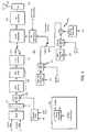
- FIG. 1 is a schematic block diagram of the system architecture incorporating the invention,
- FIG. 2 is a diagrammatic illustration of the signalling subband showing six network entry channels (NEC) frequency bins,
- FIG. 3 is a functional block diagram of the subscriber unit return link transmitter, and
- FIG. 4 is a functional block diagram of a ground station return link receiver.
- In order to describe the invention in detail, the embodiment will be discussed as it applies to the return link of a star configured spread spectrum satellite network. The
forward communications link 10 includes user signals transmitted from a hub ground station (GS) 12 through asatellite 11 which transponds them to individual users on the ground. The system will typically employ amultibeam antenna 13 which illuminates contiguous "cells" on earth. - The
hub ground station 12 includes antenna means 15 broadcasting the forward link signals 10 (which include the net entry control channel) from a plurality of control channel signal generators 16-1, 16-2...16-N to the satellite which transponds the signals to a cell on earth where thedestination handset 14 is located.Hub ground station 12 also includes a plurality of return link receivers 17-1, 17-2...17-N (the details of which are shown in Fig. 4), which are coupled to asystem controller 18 to provide time, frequency and power correction signals to the control channel generator and theforward link 10. The circuits for providing time, frequency and power correction are illustrated in the functional block diagram of Fig. 4. - Each
subscriber station 14 includes acontrol channel receiver 19 which provides the time, frequency and power correction signal from the hub ground station to the subscriber unit return link transmitter 20 )which is shown in detail in the functional block diagram of Fig. 3). - In the disclosed embodiment, the forward link signals 10 are assumed to be spread spectrum orthogonal CDMA (OCDMA) in nature, and occupying approximately 2.5 MHz. It is further assumed, for illustrative purposes, that as many as 256 CDMA signals may occupy one of the 2.5 MHz subbands. One or more of these CDMA signals is used by the GS as a "Control Channel" for communication with subscriber handsets (HS) 14 for call set up and network synchronization purposes. It is further assumed that each outbound signal contains in-band control data by which the
GS 12 can send synchronization and power control data to the HS while the HS is in active conversation. The system may employ several of the 2.5 MHz subbands. - The
GS 12 transmits in several subbands which are "stacked" into an appropriate bandwidth for transmission on the uplink to the satellite. Groups of subbands are then routed to different antenna beams orantennas 13 on the satellite for transmission to individual users on the ground. - Note that the invention disclosed herein refers primarily to the
return link 15 and does not depend on the structure of the outbound link except as regards the presence of a control channel. - The fundamental purpose of the
return link 15 is to transmit data from theuser handset HS 14 to theground station GS 12. The data transmission rate will be taken to be 4800 bps for illustrative purposes. A summary of signal parameters for this illustrative embodiment are shown in Table 1.Table 1. Summary of example signal parameters for preferred embodiment. ITEM PARAMETER VALUE COMMENTS Spreading Technique Orthogonal FH No access noise Hop Rate 150 HPS 3 hops per 20 ms frame Hop Bandwidth 1.25 MHz Hop Bin Spacing 9900 Hz 126 bins in 1.25 MHz Data Modulation OQPSK bandwidth efficient Data Rate 4800 BPS Coding Rate 1/2 Channel Rate 4950 SPS 1 symbol guard time between hops Eb/No for BER = .001 4 dB At least 4 dB better than nonsynchronous CDMA Users links in 2.5 MHz 228 - The return link 10 employs Orthogonal FH (OFH) over a 1.25 MHz subband. Hop bins are spaced by 9900 Hz and there are 126 bins in the subband, accommodating a maximum of 126 orthogonal signals.
- The hop rate is 150 HPS, giving a hop period of 6.7 ms. All signals in the subband are received in synchronism at the GS. This is achieved by closing "long" time and frequency tracking loops through the GS by way of the outbound signal control channel.
- The hop bins to be used for traffic signaling are numbered from 0 to 113 (the 12 additional bins are used for network entry as discussed below). All subscribers in a frequency subband use the same hop code sequence (h1, h2, ... hk...... hK ). The user is assigned a Traffic Channel Number (TCN) from 0 to 113. The user adds the TCN to the hop code sequence Mod (114) to determine the transmit hop bin sequence.
- Modulation is OQPSK which is bandwidth efficient, power efficient, and relatively tolerant of amplifier nonlinearities. The data is encoded with a R = 1/2 convolutional encoder. The channel transmission rate is 4950 SPS which allows one symbol guard time between hops. There are 33 symbols per hop of which 32 are data symbols. The data is detected using quasi-coherent block phase and frequency estimation techniques.
- The Viterbi decoder is implemented in a novel fashion to operate in the presence of a phase discontinuity at the hop transition. To explain this technique, let us assume that a Viterbi decoder has been successfully decoding the data up to the beginning of the present hop. The 32 bits of this hop are demodulated as soft decision symbols, however with a phase ambiguity of ninety degree multiples due to the phase discontinuity at the hop transition and ambiguity of the carrier phase estimator. We now form three other versions of the demodulated data corresponding to 90, 180, and 270 degree rotations of the carrier phase reference. Each of these sets of data is decoded by an independent decoder (total of four), each of which has been initialized to the state of the decoder which successfully decoded the data from the last hop. After the decoding, the branch metrics of the four decoders are checked to find which decoder is most likely correct. The other three decoders are then set to the same state as the successful decoder and this procedure repeated for the next hop.
- At start-up, or after a system outage due to fading, the decoding device will resolve the initial phase ambiguity after a few hops (as long as the hop period is at least a few decoder constraint lengths long). This relationship will then be maintained by the decoder device. This system may be used with either transparent or non-transparent codes.
- A second novel way to implement the Viterbi decoder operation in the presence of a phase discontinuity at the hop transition is as follows. Because the signal is OQPSK, the phase transitions on the two signal quadratures occur with a time offset of one half symbol. A device which synchronizes to the phase transitions on the received signal can then identify whether the transitions agree with the prior hop or whether there is a 90° rotation. If there is a 90° rotation, this is accounted for by swapping the data on the two signal quadratures. This leaves either a properly aligned signal in phase, or a 180° error. Similar to the above, multiple decoders are used, but now two rather than four are used. All other discussion of the prior paragraph applies to the two decoders, other than the last step where one (rather than three) decoders is set to the same state as the successful decoder.
- Both approaches for implementing the Viterbi decoder operation in the presence of a phase discontinuity at the hop transition are applicable to a broad set of applications for burst signals. These include any communication system using any form of phase-shift-keyed modulation (e.g., OQPSK, QPSK, BPSK, multi-level PSK, QASM) where the signals occur in bursts, for the first approach and OQPSK only for the second approach. These include, but are not limited to, Time Division Multiple Access, packet switching, polled networks. These systems may or may not be spread spectrum. These communication system include but are not limited to satellite, terrestrial cellular, terrestrial radio local area networks, and in-building local area networks.
- An important feature of this invention is when multiple satellites are to receive and relay the same signal for multi-satellite diversity, either switched or combining. Then by using a slow hop rate in the vicinity of, but not limited to, 1-20 hops/sec, the signals are, in a practical case, non-interfering. Consider the user links to be synchronized and operating through a satellite. All of the signals arrive at the satellite with the same timing and do not interfere with each other (they are orthogonal). When these same signals are seen at a second satellite, their relative timing is different and they interfere with one another, during the time they overlap due to relative timing offsets resulting from different locations on the earth.
- By using a slow hopping rate, say 10 hop/second, the hop dwell time is longer (100 ms vs. 6.7 ms for the 150 HPS example).
Thus, the fraction of the hop dwell which is corrupted by a 5 ms overlap, for example, is much smaller. The remaining (central) portion of each dwell, which may be in excess of 90% of each hop dwell time may be used for communications with no interference. During the overlap time, the signals could be left on with a synchronization pattern at each end to provide robust synchronization. The overlap sections at each end will not both totally be interfered with. One or the other or portions of both synchronization sections will always be observable and usable. Alternatively, the signals could be turned off in the overlap sections to conserve power to the transmitter. - The return link described above depends on all user HS signals arriving in time and frequency synchronism to remain orthogonal. Once a HS is in the network, synchronism is maintained by detecting small time and frequency errors for each user signal at the GS and sending corrections by way of the in-band control data on the outbound signal. However, initial entry of a HS into the network to place or answer a call is a problem since the HS does not have adequate information to transmit a signal which will arrive at the GS in synchronism with other traffic signals.
- This problem is partially mitigated by assuming that the GS compensates the outbound signal to remove the satellite Doppler for users in the center of the antenna beam. The user HS acquires the outbound signal and monitors the control channel before using the NEC. Thus, the HS can use the outbound signal as a time and frequency reference, however a time and frequency error will occur if the HS is off beam center. This initial uncertainty is taken to be ΔT = ± 6 ms, ΔF = ± 8 KHz for the present explanation.
- The NEC employs OFH over six frequency hop slots 25-1, 25-2...25-6 that are uniformly spaced over the 1.25 MHz traffic subband as shown in Figure 2. Each hop slot 25 is 19.8 KHz wide (two contiguous 9.9 KHz traffic hop bins).
- The hop rate is 37.5 Hz ( 150/4), and the transmit frequency starts at 1 KHz above the nominal bin center frequency and is stepped to 1 KHz below the center frequency at the middle of the hop. This transition is used for time tracking. The NEC signal parameters are summarized in Table 2.
Table 2. NEC signal parameter summary ITEM VALUE COMMENTS Hop Rate 37.5 HPS Tn = 26.7 ms compared to initial ΔT = ± 6 ms Hop Bin Width 19.8 KHz Initial ΔF = ± 8 KHz Number of Hop Bins 6 Spaced over 1.25 MHz Modulation 2 KHz frequency step at hop center Provides a transition for time sync - The hop code is formed in a similar manner to that for the traffic channels, i. e. six orthogonal hop frequency sequences are generated by adding the NEC number to a hop code sequence.
- The NEC is used by the subscriber to place or answer a call. In order to use the NEC, the user HS must have acquired the outbound signal and be monitoring the control channel. Identifiers for unoccupied NEC codes are transmitted to the HS on the control channel. There are a total of 6 codes. The HS selects one of the unoccupied NEC codes and begins to transmit using frequency and time corrections based on the outbound signal.
- The
GS 12 performs a fast fourier transform FFT (Fig. 4) centered on each of the NEC frequency bins and: - 1) Updates the list of unoccupied NEC codes as appropriate.
- 2) Detects signal collisions and notifies users.
- 3) Estimates time and frequency offsets on received signals and transmits corrections on the control channel (tagged with the NEC identifier), i.e. the time and frequency pull-in loops are closed through the GS.
- 4) When the
GS 12 determines that theHS 14 is in time and frequency sync, theHS 14 is given a traffic channel assignment. - A block diagram of the subscriber unit return link transmitter is shown in Figure 3. The multiplexed input data (control and traffice) is buffered 27 and then covered with a
long security code 28 which is synchronized with thesystem clock 29. The data is coded 30, interleaved 31 and then OQPSK modulated 32 onto the hopped carrier 33, after which it is upconverted 34 and amplified 35 for transmission viaantenna 36. Intraffic 37 andnet entry channel 38 mode, the hop timing is synchronized with the symbol timing. - The return link receiver is implemented in the ground station GS, and a functional block diagram is shown in Figure 4. The received signal is first down converted 40 and dehopped with the hop sequence synchronized to the station clock as shown. The dehopped signal is converted 41 to baseband using I and Q mixers, where it is then digitized 42.
- The sampled signal is passed through a
fourth power nonlinearity 43 to remove the data modulation. The frequency error (referenced to zero) of the resulting cw signal, which is four times that of the carrier, is measured with a frequency discriminator 44 (typically a Cross Product Discriminator or an FFT based discriminator) and passed to the system controller which computes a correction to be transmitted to theuser HS 14 on the outbound control link. - The frequency error is also averaged and passed to an Number Controlled Oscillator (NCO) 45 and complex multiplier which removes the estimated error in a feed-forward manner. A Block Phase Estimator (BPE) 46 is used to estimate the phase of the corrected output.
- The
NCO 45 output frequency is also divided 46 by four and mixed 47 with the baseband signal to yield a frequency corrected baseband signal with data modulation. This signal is demodulated 49 using the phase estimate from the BPE. As illustrated, the necessary symbol timing is also derived from the baseband signal. - The symbol synchronizer output is used in conjunction with the
hop timing discriminator 63 to calculate a very accurate estimate of the hop timing offset. This estimate is forwarded to thesystem controller 18 which computes a correction to be transmitted to the user HS on theoutbound control link 10. - The soft-decision demodulated data is deinterleaved 60 and decoded on a hop basis using four decoders 61-1...61-4 to resolve the phase ambiguity after the hop transition as described above. The selected
correct output 64 is differentially decoded 65. Asecurity code 66 is mixed with the output and demultiplexed 67 to provide the traffic data and control data. - While preferred embodiments of the invention have been described and illustrated, it will be appreciated that other embodiments of the invention will be readily apparent to those skilled in the art that various other embodiments, adaptations and modifications of the invention are possible.
Claims (5)
- A satellite network communication system in which a plurality of subscriber handset terminals (14) communicate with a ground hub station (12) on a net entry channel (NEC) and traffic channels using orthogonally frequency hopped spread spectrum orthogonal CDMA transmissions such that none of the signals occupies the same frequency bin at the same time, characterized in that,
said hub station (12) includes a control channel generator (16-1, 16-2...16-N) for generating a net entry control channel,
each subscriber handset terminal has a subscriber unit control channel receiver (19) and a subscriber unit return link transmitter (20),
said NEC having a selected number of frequency hop slots, each hop slot of the NEC being longer than that of a traffic channel and the frequency bandwidth of each hop bin of the NEC being twice the bandwidth of a traffic bin, so as to take account of initial timing and frequency uncertainties,
whereby when entering the network each subscriber handset monitors the outbound signals from the hub station, selects an unused NEC hop sequence as signalled via a net entry control channel and begins transmission on said NEC using frequency and time corrections based on said outbound signal,
the hub station transmits timing and frequency corrections to the subscriber handset to control the said subscriber unit return link transmitter (20),
and whereby, when the hub station determines that the subscriber handset is in time and frequency synchronism the subscriber handset is given a traffic channel assignment, and whereby further, after the subscriber handset has so entered the network, small time and frequency correction signals are sent to the subscriber handset via said net entry control channel,
signals from all subscriber handsets thereby arriving at the hub station in time and frequency synchronism. - The satellite network communication system defined in claim 1 further characterized in that said frequency hopping in said NEC is at a relatively slow hop rate in order to enhance performance when receiving the same user signal from two satellites simultaneously.
- The satellite network communication system defined in claim 1 further characterized in that said net entry control channel at said ground hub station includes means (61) for providing time and frequency corrections to subscriber handset terminals necessary to establish subscriber to ground hub station communications on the traffic channel.
- The satellite network communication system defined in claim 2 further characterized in that the hop rate on said net entry channels is lower than the hop rate on said traffic frequency channel.
- The satellite network communication system defined in any one of claims 1 - 4 further characterized in that each hub station and subscriber handset terminal includes means to modulate said signals on a carrier using orthogonal QPSK.
Applications Claiming Priority (3)
| Application Number | Priority Date | Filing Date | Title |
|---|---|---|---|
| US08/384,537 US5638361A (en) | 1995-02-08 | 1995-02-08 | Frequency hopped return link with net entry channel for a satellite personal communications system |
| PCT/US1996/001715 WO1996024992A1 (en) | 1995-02-08 | 1996-02-08 | Frequency hopped return link with net entry channel for a satellite personal communications system |
| US384537 | 1999-08-27 |
Publications (3)
| Publication Number | Publication Date |
|---|---|
| EP0808532A1 EP0808532A1 (en) | 1997-11-26 |
| EP0808532A4 EP0808532A4 (en) | 2002-01-02 |
| EP0808532B1 true EP0808532B1 (en) | 2006-04-19 |
Family
ID=23517712
Family Applications (1)
| Application Number | Title | Priority Date | Filing Date |
|---|---|---|---|
| EP96909483A Expired - Lifetime EP0808532B1 (en) | 1995-02-08 | 1996-02-08 | Frequency hopped return link with net entry channel for a satellite personal communications system |
Country Status (8)
| Country | Link |
|---|---|
| US (1) | US5638361A (en) |
| EP (1) | EP0808532B1 (en) |
| JP (1) | JP3209751B2 (en) |
| KR (1) | KR100354957B1 (en) |
| AT (1) | ATE323983T1 (en) |
| CA (1) | CA2210920A1 (en) |
| DE (1) | DE69636051T2 (en) |
| WO (1) | WO1996024992A1 (en) |
Families Citing this family (37)
| Publication number | Priority date | Publication date | Assignee | Title |
|---|---|---|---|---|
| JP3244610B2 (en) * | 1995-01-27 | 2002-01-07 | 株式会社日立製作所 | Frequency hopping wireless LAN system |
| ZA965340B (en) | 1995-06-30 | 1997-01-27 | Interdigital Tech Corp | Code division multiple access (cdma) communication system |
| FR2739244B1 (en) * | 1995-09-26 | 1997-11-14 | Alcatel Mobile Comm France | BASE STATION FOR CELLULAR MOBILE RADIOCOMMUNICATIONS SYSTEM AND SYSTEM FOR SYNCHRONIZING SUCH BASE STATIONS |
| US5894473A (en) * | 1996-02-29 | 1999-04-13 | Ericsson Inc. | Multiple access communications system and method using code and time division |
| AU1918597A (en) * | 1996-03-19 | 1997-10-10 | Vistar Telecommunications Inc. | Interactive satellite broadcast system |
| US5802044A (en) * | 1996-04-26 | 1998-09-01 | Motorola, Inc. | Multicarrier reverse link timing synchronization system, device and method |
| US5910945A (en) * | 1996-04-30 | 1999-06-08 | Trw Inc. | Method and apparatus for synchronizing communications in a satellite based telecommunications system |
| DE69717412T2 (en) * | 1996-09-17 | 2003-07-17 | Koninkl Philips Electronics Nv | TRANSMISSION SYSTEM WITH IMPROVED LOCK DETECTION |
| US5953327A (en) * | 1996-10-29 | 1999-09-14 | Stanford Telecommunications, Inc. | Class of low cross correlation non-palindromic synchronization sequences for code tracking in synchronous multiple access communication systems |
| US6002664A (en) * | 1997-02-24 | 1999-12-14 | At&T Wireless Services Inc. | Method to gain access to a base station in a discrete multitone spread spectrum communications system |
| US6351503B1 (en) | 1997-09-12 | 2002-02-26 | Stanford Telecommunications, Inc. | Threshold extension block phase estimator for quasi-coherent communications systems |
| US6075781A (en) * | 1997-12-12 | 2000-06-13 | Stanford Telecommunications, Inc. | Flux density reduction in OCDMA satellite communication system |
| DE69929342D1 (en) | 1998-07-21 | 2006-03-30 | Tachyon Inc | METHOD AND DEVICE FOR MULTI-ACCESS IN A COMMUNICATION SYSTEM |
| US6674730B1 (en) | 1998-08-04 | 2004-01-06 | Tachyon, Inc. | Method of and apparatus for time synchronization in a communication system |
| US6396825B1 (en) * | 1998-08-18 | 2002-05-28 | Motorola, Inc. | Method and apparatus for using a pseudo-random signal in a communication system |
| US6256483B1 (en) * | 1998-10-28 | 2001-07-03 | Tachyon, Inc. | Method and apparatus for calibration of a wireless transmitter |
| US6218896B1 (en) | 1999-08-27 | 2001-04-17 | Tachyon, Inc. | Vectored demodulation and frequency estimation apparatus and method |
| US6665292B1 (en) | 1999-08-27 | 2003-12-16 | Tachyon, Inc. | Transmission and reception of TCP/IP data over a wireless communication channel |
| US6532220B1 (en) | 1999-08-27 | 2003-03-11 | Tachyon, Inc. | System and method for efficient channel assignment |
| US6463070B1 (en) | 1999-08-27 | 2002-10-08 | Tachyon, Inc. | System and method for clock correlated data flow in a multi-processor communication system |
| US6650636B1 (en) | 1999-08-27 | 2003-11-18 | Tachyon, Inc. | Transmission and reception of TCP/IP data over a wireless communication channel |
| US6735188B1 (en) | 1999-08-27 | 2004-05-11 | Tachyon, Inc. | Channel encoding and decoding method and apparatus |
| US6674731B1 (en) | 1999-08-27 | 2004-01-06 | Tachyon, Inc. | Transmission and reception of TCP/IP data over a wireless communication channel |
| US6982969B1 (en) | 1999-09-28 | 2006-01-03 | Tachyon, Inc. | Method and system for frequency spectrum resource allocation |
| JP2001285927A (en) * | 2000-03-29 | 2001-10-12 | Matsushita Electric Ind Co Ltd | Communication terminal and wireless communication method |
| DE10103926A1 (en) * | 2001-01-30 | 2002-09-05 | Infineon Technologies Ag | Frequency scheme for data transmission systems |
| US7012972B1 (en) * | 2002-04-27 | 2006-03-14 | Wideband Semiconductors, Inc. | Minimization of phase equivocation in burst modems |
| CN1675857A (en) * | 2002-06-24 | 2005-09-28 | 高通股份有限公司 | Method for return link sychronisation in an orthogonal CDMA satellite system |
| AU2003904339A0 (en) * | 2003-08-04 | 2003-08-28 | Barrett Communications Pty Ltd | Method and system for synchronising stations within communications networks and stations for use therein |
| CN102883422A (en) * | 2005-06-17 | 2013-01-16 | 日本电气株式会社 | Communication control method, communication control system and its control program |
| US20080220771A1 (en) * | 2007-03-08 | 2008-09-11 | Viasat, Inc. | Satellite reference terminal systems and methods |
| US8532498B2 (en) * | 2008-02-08 | 2013-09-10 | Celight | Secure orthogonal frequency multiplexed optical communications |
| FR2994367B1 (en) | 2012-08-03 | 2016-07-15 | Thales Sa | METHOD AND SYSTEM FOR SYNCHRONIZATION |
| RU2534938C1 (en) * | 2013-09-10 | 2014-12-10 | Негосударственное образовательное учреждение "Саранский Дом науки и техники Российского Союза научных и инженерных общественных организаций" | Multifrequency functional generator |
| RU2534939C1 (en) * | 2013-09-13 | 2014-12-10 | Негосударственное образовательное учреждение "Саранский Дом науки и техники Российского Союза научных и инженерных общественных организаций" | Function generator |
| RU2573281C1 (en) * | 2014-12-03 | 2016-01-20 | Жанна Артуровна Сухинец | Functional converter of sinusoidal signals of frequency-code |
| CN106559103B (en) * | 2016-12-08 | 2019-03-29 | 西安烽火电子科技有限责任公司 | A kind of extensive hopped-frequency pulses system based on Beidou time service |
Family Cites Families (9)
| Publication number | Priority date | Publication date | Assignee | Title |
|---|---|---|---|---|
| US5351269A (en) * | 1990-12-05 | 1994-09-27 | Scs Mobilecom, Inc. | Overlaying spread spectrum CDMA personal communications system |
| EP0496007B1 (en) * | 1991-01-21 | 1996-07-10 | Nec Corporation | Spread packet communication system |
| IL100029A (en) * | 1991-11-11 | 1994-02-27 | Motorola Inc | Method and apparatus for improving detection of data bits in a slow frequency hopping communication system |
| US5392450A (en) * | 1992-01-08 | 1995-02-21 | General Electric Company | Satellite communications system |
| US5245634A (en) * | 1992-03-23 | 1993-09-14 | Motorola, Inc. | Base-site synchronization in a communication system |
| JPH06186317A (en) * | 1992-04-23 | 1994-07-08 | Mitsubishi Electric Corp | Position measurement system using artificial satellite |
| GB9225879D0 (en) * | 1992-12-11 | 1993-02-03 | Reilor Holdings Ltd | Improved pet door |
| US5506863A (en) * | 1993-08-25 | 1996-04-09 | Motorola, Inc. | Method and apparatus for operating with a hopping control channel in a communication system |
| US5463659A (en) * | 1994-07-05 | 1995-10-31 | At&T Ipm Corp. | Apparatus and method of configuring a cordless telephone for operating in a frequency hopping system |
-
1995
- 1995-02-08 US US08/384,537 patent/US5638361A/en not_active Expired - Lifetime
-
1996
- 1996-02-08 DE DE69636051T patent/DE69636051T2/en not_active Expired - Lifetime
- 1996-02-08 JP JP52442196A patent/JP3209751B2/en not_active Expired - Fee Related
- 1996-02-08 EP EP96909483A patent/EP0808532B1/en not_active Expired - Lifetime
- 1996-02-08 WO PCT/US1996/001715 patent/WO1996024992A1/en active IP Right Grant
- 1996-02-08 CA CA002210920A patent/CA2210920A1/en not_active Abandoned
- 1996-02-08 AT AT96909483T patent/ATE323983T1/en not_active IP Right Cessation
- 1996-02-08 KR KR1019970705367A patent/KR100354957B1/en not_active IP Right Cessation
Also Published As
| Publication number | Publication date |
|---|---|
| ATE323983T1 (en) | 2006-05-15 |
| DE69636051D1 (en) | 2006-05-24 |
| KR19980701970A (en) | 1998-06-25 |
| DE69636051T2 (en) | 2006-11-30 |
| AU692383B2 (en) | 1998-06-04 |
| US5638361A (en) | 1997-06-10 |
| CA2210920A1 (en) | 1996-08-15 |
| JP3209751B2 (en) | 2001-09-17 |
| EP0808532A1 (en) | 1997-11-26 |
| JPH11509378A (en) | 1999-08-17 |
| WO1996024992A1 (en) | 1996-08-15 |
| AU5296296A (en) | 1996-08-27 |
| KR100354957B1 (en) | 2002-12-16 |
| EP0808532A4 (en) | 2002-01-02 |
Similar Documents
| Publication | Publication Date | Title |
|---|---|---|
| EP0808532B1 (en) | Frequency hopped return link with net entry channel for a satellite personal communications system | |
| US7187903B1 (en) | Method and apparatus for timing correction in communication systems | |
| KR100506579B1 (en) | Determination of frequency in communication system | |
| US5764630A (en) | Forward link carrier recovery in an OCDMA spread spectrum communication system without a pilot tone | |
| US6839539B2 (en) | RF signal repeater in mobile communications systems | |
| US5987014A (en) | Multipath resistant, orthogonal code-division multiple access system | |
| EP0951763A2 (en) | Method for frequency division duplex communications | |
| JP2000503827A (en) | High power short message service using dedicated carrier frequency | |
| KR100791824B1 (en) | Method for precorrecting timing and frequency in communication systems | |
| EP1205040B1 (en) | Method for deep paging | |
| EP1077006B1 (en) | Flux density reduction in ocdma satellite communication system | |
| AU692383C (en) | Frequency hopped return link with net entry channel for a satellite personal communications system | |
| EP1052788A1 (en) | Broadcast control channel reception in a mobile satellite telephone system | |
| AU713299C (en) | Forward link carrier recovery in an OCDMA spread spectrum communication system without a pilot tone | |
| CA2248625C (en) | Forward link carrier recovery in an ocdma spread spectrum communication system without a pilot tone | |
| AU2004203062B2 (en) | Method for deep paging | |
| Vernucci | Channel-Access Schemes | |
| Salivahanan et al. | Cellular Mobile Telephony-A Spread Spectrum Approach |
Legal Events
| Date | Code | Title | Description |
|---|---|---|---|
| PUAI | Public reference made under article 153(3) epc to a published international application that has entered the european phase |
Free format text: ORIGINAL CODE: 0009012 |
|
| 17P | Request for examination filed |
Effective date: 19970804 |
|
| AK | Designated contracting states |
Kind code of ref document: A1 Designated state(s): AT BE CH DE DK ES FR GB GR IE IT LI NL PT SE |
|
| RIN1 | Information on inventor provided before grant (corrected) |
Inventor name: NATALI, FRANCIS, D. Inventor name: OHLSON, JOHN |
|
| RIC1 | Information provided on ipc code assigned before grant |
Free format text: 7H 04J 3/06 A, 7H 04J 13/06 B, 7H 04B 1/713 B, 7H 04B 7/216 B |
|
| A4 | Supplementary search report drawn up and despatched |
Effective date: 20011109 |
|
| AK | Designated contracting states |
Kind code of ref document: A4 Designated state(s): AT BE CH DE DK ES FR GB GR IE IT LI NL PT SE |
|
| 17Q | First examination report despatched |
Effective date: 20020325 |
|
| GRAP | Despatch of communication of intention to grant a patent |
Free format text: ORIGINAL CODE: EPIDOSNIGR1 |
|
| GRAS | Grant fee paid |
Free format text: ORIGINAL CODE: EPIDOSNIGR3 |
|
| GRAA | (expected) grant |
Free format text: ORIGINAL CODE: 0009210 |
|
| RAP1 | Party data changed (applicant data changed or rights of an application transferred) |
Owner name: ALCATEL USA SOURCING, L.P. |
|
| AK | Designated contracting states |
Kind code of ref document: B1 Designated state(s): AT BE CH DE DK ES FR GB GR IE IT LI NL PT SE |
|
| PG25 | Lapsed in a contracting state [announced via postgrant information from national office to epo] |
Ref country code: NL Free format text: LAPSE BECAUSE OF FAILURE TO SUBMIT A TRANSLATION OF THE DESCRIPTION OR TO PAY THE FEE WITHIN THE PRESCRIBED TIME-LIMIT Effective date: 20060419 Ref country code: LI Free format text: LAPSE BECAUSE OF FAILURE TO SUBMIT A TRANSLATION OF THE DESCRIPTION OR TO PAY THE FEE WITHIN THE PRESCRIBED TIME-LIMIT Effective date: 20060419 Ref country code: IT Free format text: LAPSE BECAUSE OF FAILURE TO SUBMIT A TRANSLATION OF THE DESCRIPTION OR TO PAY THE FEE WITHIN THE PRE;WARNING: LAPSES OF ITALIAN PATENTS WITH EFFECTIVE DATE BEFORE 2007 MAY HAVE OCCURRED AT ANY TIME BEFORE 2007. THE CORRECT EFFECTIVE DATE MAY BE DIFFERENT FROM THE ONE RECORDED.SCRIBED TIME-LIMIT Effective date: 20060419 Ref country code: CH Free format text: LAPSE BECAUSE OF FAILURE TO SUBMIT A TRANSLATION OF THE DESCRIPTION OR TO PAY THE FEE WITHIN THE PRESCRIBED TIME-LIMIT Effective date: 20060419 Ref country code: BE Free format text: LAPSE BECAUSE OF FAILURE TO SUBMIT A TRANSLATION OF THE DESCRIPTION OR TO PAY THE FEE WITHIN THE PRESCRIBED TIME-LIMIT Effective date: 20060419 Ref country code: AT Free format text: LAPSE BECAUSE OF FAILURE TO SUBMIT A TRANSLATION OF THE DESCRIPTION OR TO PAY THE FEE WITHIN THE PRESCRIBED TIME-LIMIT Effective date: 20060419 |
|
| REG | Reference to a national code |
Ref country code: GB Ref legal event code: FG4D |
|
| REF | Corresponds to: |
Ref document number: 69636051 Country of ref document: DE Date of ref document: 20060524 Kind code of ref document: P |
|
| REG | Reference to a national code |
Ref country code: IE Ref legal event code: FG4D |
|
| PG25 | Lapsed in a contracting state [announced via postgrant information from national office to epo] |
Ref country code: SE Free format text: LAPSE BECAUSE OF FAILURE TO SUBMIT A TRANSLATION OF THE DESCRIPTION OR TO PAY THE FEE WITHIN THE PRESCRIBED TIME-LIMIT Effective date: 20060719 Ref country code: DK Free format text: LAPSE BECAUSE OF FAILURE TO SUBMIT A TRANSLATION OF THE DESCRIPTION OR TO PAY THE FEE WITHIN THE PRESCRIBED TIME-LIMIT Effective date: 20060719 |
|
| PG25 | Lapsed in a contracting state [announced via postgrant information from national office to epo] |
Ref country code: ES Free format text: LAPSE BECAUSE OF FAILURE TO SUBMIT A TRANSLATION OF THE DESCRIPTION OR TO PAY THE FEE WITHIN THE PRESCRIBED TIME-LIMIT Effective date: 20060730 |
|
| PG25 | Lapsed in a contracting state [announced via postgrant information from national office to epo] |
Ref country code: PT Free format text: LAPSE BECAUSE OF FAILURE TO SUBMIT A TRANSLATION OF THE DESCRIPTION OR TO PAY THE FEE WITHIN THE PRESCRIBED TIME-LIMIT Effective date: 20060919 |
|
| NLV1 | Nl: lapsed or annulled due to failure to fulfill the requirements of art. 29p and 29m of the patents act | ||
| REG | Reference to a national code |
Ref country code: CH Ref legal event code: PL |
|
| ET | Fr: translation filed | ||
| PLBE | No opposition filed within time limit |
Free format text: ORIGINAL CODE: 0009261 |
|
| STAA | Information on the status of an ep patent application or granted ep patent |
Free format text: STATUS: NO OPPOSITION FILED WITHIN TIME LIMIT |
|
| 26N | No opposition filed |
Effective date: 20070122 |
|
| PG25 | Lapsed in a contracting state [announced via postgrant information from national office to epo] |
Ref country code: IE Free format text: LAPSE BECAUSE OF NON-PAYMENT OF DUE FEES Effective date: 20070208 |
|
| PG25 | Lapsed in a contracting state [announced via postgrant information from national office to epo] |
Ref country code: GR Free format text: LAPSE BECAUSE OF FAILURE TO SUBMIT A TRANSLATION OF THE DESCRIPTION OR TO PAY THE FEE WITHIN THE PRESCRIBED TIME-LIMIT Effective date: 20060720 |
|
| REG | Reference to a national code |
Ref country code: FR Ref legal event code: PLFP Year of fee payment: 20 |
|
| PGFP | Annual fee paid to national office [announced via postgrant information from national office to epo] |
Ref country code: DE Payment date: 20150203 Year of fee payment: 20 |
|
| PGFP | Annual fee paid to national office [announced via postgrant information from national office to epo] |
Ref country code: GB Payment date: 20150204 Year of fee payment: 20 Ref country code: FR Payment date: 20150210 Year of fee payment: 20 |
|
| REG | Reference to a national code |
Ref country code: DE Ref legal event code: R071 Ref document number: 69636051 Country of ref document: DE |
|
| REG | Reference to a national code |
Ref country code: GB Ref legal event code: PE20 Expiry date: 20160207 |
|
| PG25 | Lapsed in a contracting state [announced via postgrant information from national office to epo] |
Ref country code: GB Free format text: LAPSE BECAUSE OF EXPIRATION OF PROTECTION Effective date: 20160207 |