EP0809126A1 - Gradient index multifocal lens, spectacle lens, and manufacture of gradient index multifocal lens - Google Patents
Gradient index multifocal lens, spectacle lens, and manufacture of gradient index multifocal lens Download PDFInfo
- Publication number
- EP0809126A1 EP0809126A1 EP96933640A EP96933640A EP0809126A1 EP 0809126 A1 EP0809126 A1 EP 0809126A1 EP 96933640 A EP96933640 A EP 96933640A EP 96933640 A EP96933640 A EP 96933640A EP 0809126 A1 EP0809126 A1 EP 0809126A1
- Authority
- EP
- European Patent Office
- Prior art keywords
- multifocal lens
- progressive
- progressive multifocal
- lens
- vision region
- Prior art date
- Legal status (The legal status is an assumption and is not a legal conclusion. Google has not performed a legal analysis and makes no representation as to the accuracy of the status listed.)
- Granted
Links
Images


Classifications
-
- G—PHYSICS
- G02—OPTICS
- G02C—SPECTACLES; SUNGLASSES OR GOGGLES INSOFAR AS THEY HAVE THE SAME FEATURES AS SPECTACLES; CONTACT LENSES
- G02C7/00—Optical parts
- G02C7/02—Lenses; Lens systems ; Methods of designing lenses
- G02C7/06—Lenses; Lens systems ; Methods of designing lenses bifocal; multifocal ; progressive
- G02C7/061—Spectacle lenses with progressively varying focal power
- G02C7/068—Special properties achieved by the combination of the front and back surfaces
Definitions
- the present invention relates to a progressive multifocal lens for correction of vision, and a manufacturing method of a progressive multifocal and an eyeglass lens using it.
- a progressive multifocal lens is a lens comprising two field sections having different refractive power, and a field section wherein the refractive power changes progressively between these. It is superior in external appearance, as there are no boundaries in these field sections. Furthermore, fields having different refractive powers in a single lens can be obtained. Therefore, it is used widely as an eyeglass lens having vision correcting functions for aging vision (presbyopia) and the like.
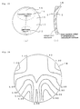
- Fig. 25 shows the general structure of a conventional progressive multifocal lens used widely as an eyeglass lens.
- This progressive multifocal lens 1 is provided on the upper side with a distance-vision region 11 being a field section for seeing objects at a far distance.
- a field section for seeing objects at a near distance having a different refractive power from the distance-vision region 11 is provided on the lower side as a near-vision region 12.
- the distance-vision region 11 and near-vision region 12 are joined smoothly by a progressive region 13 being a field section having a refractive power that changes continuously for seeing objects at an intermediate distance between the far distance and the near distance.
- a single lens 1 used for an eyeglass all the capabilities required for an eyeglass, for example, a vertex power matching the user's prescription, a cylinder power for correcting astigmatism, an addition power for correcting aging vision, and furthermore a prism power for correcting skew, must be provided by the two surfaces being a refractive surface 2 on the side of the eye and a refractive surface 3 on the side of the observed object. Therefore, in a conventional progressive multifocal lens 1, as shown in Fig. 25, a progressive refractive surface 5 providing a refractive power that changes continuously in order to compose the distance-vision region 11, near-vision region 12, and progressive region 13, is formed on the refractive surface 3 on the side of the object.
- the refractive surface 2 is used as a refractive surface, or the like, for correcting astigmatism as described above.
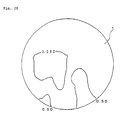
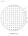
- Fig. 26 shows the astigmatism obtained with the conventional progressive multifocal lens 1
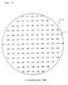
- Fig. 27 shows the summary distribution of the z coordinates of the progressive refractive surface 5 formed on the refractive surface 3 of the conventional progressive multifocal lens on the side of the object.
- the plane surface is represented as the xy coordinates
- the direction showing the thickness of the lens perpendicular to this xy plane is represented as the z coordinates.
- the up-and-down direction when the lens 1 is worn as an eyeglass lens is the y coordinate
- the left-right direction is the x coordinate.
- the progressive refractive face 5 is non-spherical so as to change continuously the refractive power, the curvature changes according to each region of the surface. Consequently, as understood from Fig. 26, even in a progressive multifocal lens 1 not for correction of astigmatism having the surface 2 on the side of the eye as a spherical surface, if a progressive refractive surface 5 is introduced on the surface 3 on the side of the object, an astigmatic aberration is generated on the surface by the difference in curvature in the x direction and the y direction.
- This astigmatic aberration is represented in diopter (D) units, and the drawing of astigmatic aberration shown in Fig. 26 is a drawing having the regions of specific diopters connected by contour lines.
- a user of an eyeglass not having astigmatism can obtain clear vision without perceiving so much the fading of an image if the astigmatic aberration appearing in the lens is 1.0 diopters or less, preferably 0.5 diopters or less. Therefore, a clear vision region 21 having an astigmatic aberration of 1.0 diopters or less, or preferably 0.5 diopters or less, is placed extending from the distance-vision region to the near-vision region following the main line of sight (umbilical meridian) 14 somewhat bent on the side of the nose, crowding the vision.
- the main line of sight 14 in particular, an astigmatic aberration is not generated by substantially eliminating the difference in curvature in the x direction and in the y direction. Consequently, the astigmatic aberration appears greater because the lens 1 becomes non-spherical in the direction of the perimeter from the main line of sight 14.
- An eyeglass lens 9 is formed by "globe processing", i.e. processing the outer shape of the lens 1 into a shape matching the eyeglass frame, and is provided to the user.
- the lens 1 shown in Fig. 26 and Fig. 27 is a lens wherein the base curve Pb, showing the fundamental refractive power of the surface 3 on the side of the object having the progressive refractive surface 5 applied, is 4.00D, the addition Pa is 2.00D, the surface refractive power D2 of the surface 2 on the side of the eye is 6.00D, the center thickness t of the lens is 3.0mm, and the diameter d of the lens is 70.0mm.
- Fig. 28 shows a conventional progressive multifocal lens 1 for astigmatism wherein a toric surface 6 having a cylinder power C for correcting astigmatism is formed on the surface 2 on the side of the eye.
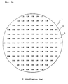
- Fig. 29 shows a drawing of the astigmatic aberration of this lens.
- Fig. 30 shows the z coordinates of the toric surface 6.
- the lens showing astigmatic aberration in Fig. 29 has a cylinder power C of -2.00D.
- the other conditions are identical to the lens showing astigmatic aberration in Fig. 26.
- This progressive multifocal lens 1 for astigmatism has an astigmatic aberration of 2.00D introduced substantially uniformly in order to correct the astigmatism following the main line of sight 14.
- An eyeglass lens 9 can be formed by globe processing according to the eyeglass frame identically to that mentioned above.
- an eyeglass lens is sold on the market that corrects astigmatism, wherein the refractive power changes continuously from the distance-vision region to the near-vision region using a progressive refractive surface, and it is used widely as a means to correct vision.
- the progressive multifocal lens has a high prescription to become a measure for correction of vision, and if the addition, being the difference in refractive power between the distance-vision region and the near-vision region, is great, the astigmatic aberration appearing in the lens also becomes great because the progressive refractive surface is made further non-spherical.
- jumping and warping of images can be improved by suppressing the variation of astigmatic aberration.
- jumping and warping of images are also caused by differences in refractive power between the distance-vision region and the near-vision region. That is, the distance-vision region 11 has a refractive power whereby the focus is at a distance, while the near-vision region 12 has a refractive power different from that of the distance-vision region 11 whereby the focus is near. Consequently, in the progressive region 13, because the magnification gradually varies, this is one main reason why the acquired images jump and are distorted.
- the aim is to provide a progressive multifocal lens capable of improving the jumping and warping of images caused by variation of the magnification between the distance-vision region and the near-vision region of the progressive multifocal lens.
- the aim is to provide a progressive multifocal lens and eyeglass lens that can reduce more greatly the jumping and warping of images while approaching the limits in the design of the progressive refractive surface, and that can provide a more comfortable visual field to the user. Also, the aim is to provide a progressive multifocal lens and eyeglass lens that can provide clear vision having little jumping and warping even for users having a great difference in prescription (addition between the distance-vision region and the near-vision region, which easily generates jumping and warping of images.
- the inventors of the present invention have focused on the placement of the progressive refractive surface contributing to magnification of a progressive multifocal lens, and have discovered that it is possible to reduce the difference of magnification between the distance-vision region and the near-vision region by introducing the progressive refractive surface on the side of the eye.
- the present invention is a progressive multifocal lens for correction of vision, comprising a distance-vision region and a near-vision region having different refractive power, and a progressive region wherein the refractive power between these changes progressively, wherein a curvature of the progressive surface for composing the distance-vision region, near-vision region, and progressive region are provided on the surface of the progressive multifocal lens on the side of the eye.
- Mp is the power factor.
- Ms is called the shape factor.
- L the distance from the vertex (internal vertex) of the surface of the lens on the side of the eye to the eye is represented below as L, the refractive power of the internal vertex (internal vertex power) as Po, the center thickness of the lens as t, the refractivity of the lens as n, the base curve (refractive power) of the surface of the lens on the side of the object as Pb.
- Mp 1 / (1 - L x Po)
- Ms 1 / (1 - (t x Pb) / n)
- diopters (D) is used regarding the internal vertex power Po and the base curve Pb, and meters (m) is used regarding the distance L and thickness t.
- the internal vertex power Po contributes to the correction of vision in the distance-vision region and the near-vision region, and it is understood that, for maintaining the internal vertex power of a required value, the variation of the magnification SM can be controlled by suppressing the variation of the base curve Pb of the surface on the side of the object. For example, if the base curve Pb of the convex surface on the side of the object is made constant, the variation of the magnification MS due to the shape factor Ms can be eliminated.
- the base curve Pb on the side of the object cannot be made constant. Furthermore, the variation of the shape factor Ms becomes greater as the addition becomes greater. Jumping and warping of images increases.
- the difference in magnification between the distance-vision region and the near-vision region can be held to a necessary minimum. Because the variation of the magnification in the progressive region can be suppressed as well, even if the performance according to the distortion of images is the same extent as a conventional progressive multifocal lens, a progressive multifocal lens and eyeglass lens can be provided whereby the jumping and warping of images is reduced, and a more comfortable visual field can be provided to the user. Particularly, in a progressive multifocal lens having a great addition, the jumping and warping can be reduced.
- Fig. 2 compares the magnification achieved by a progressive multifocal lens of the present invention having a base curve Pd of 5.00D, an addition of 3.00D, a spherical power S of 2.00D, a refractivity n of 1.662, and a distance L of 15.0mm as an example, and the magnification achieved by a conventional progressive multifocal lens having the progressive refractive surface on the side of the object.
- the difference in magnification between the distance-vision region and the near-vision region can be suppressed to 80% of the conventional difference of magnification. Jumping and warping of images are prevented to a great degree.
- FIG. 3 shows, as an example, the difference of magnification between the distance-vision region and the near-vision region of a progressive multifocal lens pertaining to the present invention having a progressive refractive surface on the surface (concave surface) on the side of the eye, wherein the base curve Pd for the above-mentioned lens is 4.00D, and the spherical power S is 0.00D.
- the difference of magnification between the distance-vision region and the near-vision region of a conventional progressive multifocal lens having the progressive refractive surface on the surface (convex surface) on the side of the object is shown.
- the progressive multifocal lens of the present invention it is possible to use the same extent of difference of magnification as that of a conventional progressive multifocal lens having a higher addition Pa from rank 1 at a low addition power region to rank 2 at a high addition power region (where rank 1 corresponds to 0.25D, rank 2 corresponds to 0,50D etc.).
- rank 1 corresponds to 0.25D
- rank 2 corresponds to 0,50D etc.
- the jumping and warping of images perceived by the user also can be suppressed to the same extent as a conventional rank 1 or rank 2 addition lens.
- the curvature of the progressive refractive surface is provided to the surface on the side of the eye, the curvature of the progressive refractive surface (reciprocal of the radius of curvature) following the main line of sight becomes smaller in the near-vision region compared with the distance-vision region.
- the curvature of the progressive refractive surface becomes smaller in at least one region as it departs from the main line of sight. Also, in the near-vision region, the curvature of the progressive refractive surface becomes greater in at least on region as it departs from the main line of sight.
- this range of addition is expressed as follows using the average surface refractive power D1 on the side of the eye in the vicinity of the main line of sight of the distance-vision region, and the average surface refractive power D2 on the side of the eye in the vicinity of the main line of sight of the near-vision region.
- D1 surface refractive power
- D2 average surface refractive power
- the curvature of the progressive refractive surface have the curvature of two orthogonal directions be equal in at least one region of the main line of sight.
- a progressive multifocal lens for correction of astigmatism wherein the surface on the side of the eye has the astigmatism correcting properties can be provided by applying the curvature of an astigmatism correcting toric surface to the surface on the side of the eye. That is, the surface on the side of the eye is the progressive refractive surface. Furthermore, a progressive multifocal lens having cylinder power can be provided.
- the progressive multifocal lens having astigmatism correcting properties of the present invention the difference of magnification between the distance-vision region and the near-vision region can be held to a minimum as described above, and a more comfortable visual field can also be provided to a user having astigmatism, there being little warping and jumping of images in addition to being able to correct astigmatism.
- a progressive multifocal lens having vision correcting properties and astigmatism correcting properties applied to the surface on the side of the eye can be manufactured by a manufacturing method comprising a first process that determines a progressive refractive surface (henceforth, original progressive refractive surface) only for the purpose that the surface on the side of the eye demonstrates the desired vision correcting properties, a second process that determines a toric surface (henceforth, original toric surface) only for the purpose that the surface on the side of the eye demonstrates the intended astigmatism correcting properties, and a third process that determines the surface of the progressive multifocal lens on the side of eye from the original progressive refractive surface and the original toric surface.
- a manufacturing method comprising a first process that determines a progressive refractive surface (henceforth, original progressive refractive surface) only for the purpose that the surface on the side of the eye demonstrates the desired vision correcting properties, a second process that determines a toric surface (henceforth, original toric surface
- a progressive multifocal lens By introducing to the surface on the side of the eye a progressive refractive surface wherein the original progressive refractive surface and the original toric surface are composed, a progressive multifocal lens can be realized, having both functions being an astigmatism correcting function using the toric surface and a vision correcting function for correction other than astigmatism using the progressive refractive surface, and furthermore, having little jumping and warping.
- a progressive multifocal lens for correction of astigmatism can be provided having an astigmatism correcting capability and a vision correcting function equal to the conventional progressive multifocal lens and, furthermore, having a small difference in magnification and improved jumping and warping.
- Z (Cp+Cx)X 2 +(Cp+Cy)Y 2 1+ (1-(Cp+Cx) 2 X 2 -(Cp+Cy) 2 Y 2 )
- X and Y indicate arbitrary points on the x and y coordinates, respectively, on the surface on the side of the eye, and Z indicates the z coordinate in the perpendicular direction of the surface on the side of the eye.
- Curvature Cp is the approximate curvature at any point p (X, Y, Z) of the original progressive refractive surface
- curvature Cx is the curvature in the x direction of the toric surface for correction of astigmatism
- curvature Cy is the curvature in the y direction.
- the average curvature of the radial direction is used as the approximate curvature Cp, and the reciprocals of the circular radius passing through the three points in the xy plane perpendicular to the z axis (passing through the center of the lens or the internal vertex (0, 0, 0)), including any point p (X, Y, Z) on the original refractive surface, the point p' (-X, -Y, Z) rotationally symmetric with point p, and the internal vertex (0, 0, 0) are used.
- a progressive multifocal lens for correction of vision on the side of the eye and furthermore, a progressive multifocal lens comprising a progressive refractive surface on the side of the eye, having both vision correcting and astigmatism correcting properties, can be provided, and an eyeglass lens for a wide range of users covering a range from users not having astigmatism to users requiring correction of astigmatism can be realized. Therefore, it becomes possible to provide to the market eyeglass lenses having little jumping and warping using a series of progressive multifocal lenses for all users.
- the progressive multifocal lens can be made lightweight.
- a progressive multifocal lens of the present invention can be provided, having a progressive refractive surface on the side of the eye as a meniscus applied to an eyeglass lens.
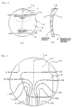
- Fig. 4 shows a progressive multifocal lens 10 of the present invention having a progressive refractive surface 5 on the surface 2 on the side of the eye.
- the progressive multifocal lens 10 of the present embodiment is provided with a distance-vision region 11 on the upper side, being a vision section for seeing objects at far distances, and a vision section for seeing objects at close distances having a refractive power different from the distance-vision region 11 is provided on the lower side as a near-vision region 12.
- the distance-vision region 11 and the near-vision region 12 are joined smoothly by a progressive region 13 wherein the refractive power varies continuously.
- the progressive multifocal lens 10 of the present embodiment has a non-spherical progressive refractive surface 5 on the surface 2 on the side of the eye to form the distance-vision region 11, the near-vision region 12, and the progressive region 13. Therefore, the surface 3 on the side of the object can be formed spherically whereby the base curve Pd becomes constant. Consequently, as explained using Equations (1)-(3) above, the difference in magnification between the distance-vision region 11 and the near-vision region 12 becomes smaller, and the rate by which the magnification changes in the progressive region 13 can be made smaller. Consequently, compared with a conventional progressive multifocal lens having a progressive refractive surface on the side of the object, the jumping and distortion of images caused by the difference in magnification can be reduced to a great extent.
- Fig. 5 and Fig. 6 show the astigmatic aberration of a progressive multifocal lens 10 of the present invention having a progressive refractive surface on the surface 2 on the side of the eye, and the z coordinates of the surface 2 on the side of the eye, that is, the progressive refractive surface 5.
- the progressive multifocal lens 10 of the present embodiment is designed such that the same degree of astigmatic aberration can be obtained as with a conventional progressive multifocal lens having the progressive refractive surface on the surface 3 on the side of the object.
- the progressive multifocal lens 10 shown in Fig. 5 and Fig. 6 has a spherical surface 3 on the side of the object, and the base curve Pb indicating its refractive power is a constant at 4.00D.
- the average surface refractive power of the distance-vision region 11 is set to 6.00D
- the average surface refractive power of the near-vision region 12 is set to 4.00D
- the addition Pa to 2.00D the spherical power S of the distance-vision region
- the center thickness of the lens is 3.0mm
- the lens diameter d is 70.0mm.
- a progressive refractive surface 5 such as shown in Fig. 4 can be provided to the surface 2 on the side of the eye.
- a progressive multifocal lens 10 can be obtained, having an astigmatic aberration such as shown in Fig. 5.
- the astigmatic aberration of the progressive multifocal lens 10 of the present embodiment shown in Fig. 5 is substantially the same as the astigmatic aberration of the conventional progressive multifocal lens shown in Fig. 26.
- a progressive multifocal lens 10 can be realized, having the identical performance as a conventional progressive multifocal lens having the progressive refractive surface provided on the surface 3 on the side of the object, even when the progressive refractive surface 5 is provided on the surface 2 on the side of the eye.
- the progressive multifocal lens 10 of the present embodiment is a progressive multifocal lens having the identical properties as conventionally, whereby a clear vision region is secured sufficiently, and having little distortion and jumping of images caused by variation of the astigmatic aberration. Furthermore, in the progressive multifocal lens 10 of the present embodiment, when comparing the difference of magnification between the distance-vision region 11 and the near-vision region 12, the magnification of the distance-vision region is 0.976, the magnification of the near-vision region is 1.007, and their difference is 0.031.
- the magnification of the distance-vision region is 0.976
- the magnification of the near-vision region is 1.011
- their difference is 0.035.
- the jumping and distortion of images caused in a progressive multifocal lens by the difference in magnification can be improved further. Therefore, an eyeglass lens 9 that is clearer, whereby the jumping and distortion are improved greatly, can be provided by globe processing the progressive multifocal lens 10 of the present embodiment to match the eyeglass frame.
- Fig. 7 shows the variation of the radius of curvature of the progressive refractive surface 5 following the main line of sight 14.
- the z coordinates of this drawing have the direction of the viewed object set to negative, and the direction of the eye set to positive.
- the value of the refractive power of the distance-vision region 11 is smaller than the value of the refractive power of the near-vision region 12, that is, they are set such that it becomes negative when the value of the refractive power of the near-vision region is subtracted from the value of the refractive power of the distance-vision region 11.
- the radius of curvature r1 of the progressive multifocal lens 10 of the present embodiment is smaller than the radius of curvature r2. Consequently, if the respective radii of curvature r1 and r2 are represented by the reciprocal curvatures C1 and C2, the curvature C1 of the distance-vision region 11 and the curvature C2 of the near-vision region 12 must satisfy the following relationship. C1 > C2
- the curvature C3 and the curvature C4 become equal.
- the near-vision region 12 it is possible to secure a wide clear-vision region by making the surface 2 on the side of the eye composing the near-vision region 12 as a spherical surface, as well as to concentrate the progressive region 13 in the vicinity of the distance-vision region 11.
- the curvature C5 and the curvature C6 become equal.
- n is the refractivity of the lens material composing the progressive multifocal lens 10 of the present embodiment.
- the addition Pd can be represented by the difference between the average surface refractive power D1 of the distance-vision region 11 and the average surface refractive power D2 of the near-vision region 12. Furthermore, because the curvature C1 of the distance-vision region 11 is greater than the curvature C2 of the near-vision region 12, as shown in Equation (7), in the surface 2 on the side of the eye, the average surface refractive power D1 of the distance-vision region 11 becomes greater than the average surface refractive power D2 of the near-vision region 12.
- the difference in magnification between the distance-vision region 11 and the near-vision region 12 can be reduced for a wide range of progressive multifocal lenses from a progressive multifocal lens having an addition of 3.5 diopters for users having substantially no power of accommodation to a progressive multifocal lens having an addition of 0.5 diopters when aging vision is not substantially advanced, and a comfortable visual field can be provided to the user by suppressing the jumping and warping of images.
- the main line of sight 14 does not become an aggregate of umbilical points, as shown in the next embodiment, and a substantially uniform astigmatic aberration is applied to the main line of sight 14 in order to correct the astigmatism.
- the refractive power Pt following the main line of sight 14 becomes such that a degree is obtained generally being more positive than the refractive power Ps in the orthogonal direction. Consequently, in such a case, in order that the astigmatic aberration be canceled by the refractive powers Pt and Ps, as shown in the following Equation (12), it is desirable that the curvatures C1 and C2 following the main line of sight 14 be rather larger than the curvatures C3 and C5 in the orthogonal directions.
- the progressive multifocal lens 10 of the present embodiment has the surface 2 on the side of the eye as the progressive refractive surface 5, the lens of the distance-vision region 11 becomes thicker than that of the near-vision region 12. Consequently, in order to make the progressive multifocal lens 10 thinner and lighter, it is desirable that a 270° base prism be applied not for the purpose of correction of vision. By this, an extremely thin progressive multifocal lens 10 can be realized as shown in Fig. 9(b).
- the direction of the prism base is represented as the counter-clockwise angle based on a horizontal line, seeing the direction in which a light beam introduced perpendicularly to the surface 2 of the lens on the side of the eye inclines due to the prism effect, from the surface 3 on the side of the object.
- the optimal value for the user can be selected between 0.25-3.00 prism diopters.
- the internal vertex power (vertex power) Ps of the distance-vision region 11, the addition power Pa, and the refractive power (base curve) Pb of the surface 2 the progressive multifocal lens on the side of the object must be set so as to satisfy the following Equation (6) described above.
- vertex power Ps By selecting the vertex power Ps, addition Pa, and base curve Pb so as to satisfy this Equation (6), it can be made as a meniscus-shaped progressive multifocal lens 10, and an eyeglass lens fitting the face can be provided.
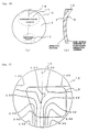
- Fig. 10 shows a progressive multifocal lens 10 having the properties of a progressive refractive surface and a toric surface provided on the surface of the present invention on the side of the eye.
- the progressive refractive surface of the present embodiment having both functions of vision correcting properties and astigmatism correcting properties formed on the surface 2 on the side of the eye
- the progressive refractive surface established only for the purpose that the surface on the side of the eye demonstrate the desired vision correcting properties is called the original progressive refractive surface
- the toric surface established only for the purpose that the surface on the side of the eye demonstrate the intended astigmatism correcting properties is called the original toric surface
- the progressive multifocal lens 10 of the present embodiment is designed and manufactured by a procedure shown using the flow chart in Fig. 13.
- the original progressive refractive surface is sought by parameters meeting the conditions of the user such as the extent of aging vision and the method of using eyeglasses, and that result is recorded as coordinates or curvatures, or the like.
- the original toric surface for correcting the user's astigmatism is sought, and that result is recorded as curvatures. Of course, it may be recorded also as coordinates.
- step ST3 all the coordinates of the surface on the side of the eye having the vision correcting and astigmatism correcting properties are sought using the results of step ST1 and ST2.
- the values Z of the z coordinates of the surface 2 on the side of the eye are sought using the following Composite Equation (5) as described above.
- Z (Cp+Cx)X 2 +(Cp+Cy)Y 2 1+ (1-(Cp+Cx) 2 X 2 -(Cp+Cy) 2 Y 2 )
- a progressive multifocal lens can be provided, having a function that performs correction of astigmatism for correction of vision, just as with the conventional progressive multifocal lens shown in Fig. 28.
- Fig. 11 shows a drawing of the astigmatic aberration of the progressive multifocal lens 10 of the present invention, corresponding to the conventional progressive multifocal lens shown in Fig. 29, having progressive refractive surface on the surface 3 on the side of the object, and a toric surface on the surface 2 on the side of the eye.
- Fig. 12 shows the values of the z coordinates of the progressive multifocal lens 10 of the present embodiment.
- the progressive multifocal lens 10 of the present invention is formed using this surface 2 on the side of the eye and a spherical surface 3 on the side of the object, and a progressive multifocal lens for correction of astigmatism such as shown in Fig. 11 can be obtained, having substantially identical astigmatic aberration as that of Fig. 29. Consequently, according to the present invention, a progressive multifocal lens 10 can be obtained, having the equivalent vision correcting power and astigmatism correcting power as the conventional progressive multifocal lens having the progressive refractive surface on the surface 3 on the side of the object and the toric surface on the surface 2 on the side of the eye.
- the curvature of a toric surface for correction of astigmatism can be applied to the surface on the side of the eye in addition to the curvature of a progressive refractive surface for correction of vision, and it can be made such that the surface on the side of the eye has an astigmatism correcting property, that is, a cylinder power.
- a progressive refractive surface having vision correcting power and astigmatism correcting power can be prepared on the side of the eye, in addition to the vision correcting power and the astigmatism correcting power, the difference in magnification between the distance-vision region 11 and the near-vision region 12 can be made less, and a progressive multifocal lens 10 can be provided, whereby the jumping and warping of images is improved.
- the base curve Pb indicating the refractive power of the surface 3 on the side of the object is a constant 4.00D.
- the average surface refractive power of the distance-vision region 11 is set to 6.00D
- the average surface refractive power of the near-vision region 12 is set to 4.00D
- the addition Pa is set to 2.00D.
- a toric surface is composed, having an astigmatic axis of 90°, a spherical power S of -2.00D, and a cylinder power C of -2.00D.
- the center thickness t of the lens is 3.0mm
- the lens diameter d is 70.0mm.
- Fig. 15 shows a lens 19 having a progressive refractive surface having formed a surface 2 on the side of the eye by adding the values of the z coordinates of the original toric surface shown in Fig. 30 to the values of the z coordinates of the original progressive refractive surface shown in Fig. 6 instead of using Composite Equation (5) mentioned above.
- Fig. 16 shows a drawing of the astigmatic aberration of the lens 19
- Fig. 17 shows the z coordinates of the surface 2 of the lens 19 on the side of the eye.
- a progressive refractive surface can be formed, having vision correcting properties and astigmatism correcting properties by adding the values of the z coordinates of the original toric surface to the values of the z coordinates of the original progressive refractive surface.
- Composite Equation (5) described above is not used, it is clear that it is difficult to achieve an astigmatic aberration equivalent to that of the conventional progressive multifocal lens shown in Fig. 29, and it is difficult to achieve vision correcting and astigmatism correcting powers exactly equal to those of the conventional progressive multifocal lens for correction of astigmatism.
- the astigmatic aberration in the perimeter area of the lens 19 is great, and it is difficult to secure an astigmatic aberration for correction of astigmatism.
- the variation of the astigmatic aberration is comparatively large, compared with the progressive multifocal lens 10 manufactured using Composite Equation (5), the images easily jump and warp when the eye moves following the main line of sight.
- a progressive multifocal lens can be provided, having secured a visual field being one step more comfortable and having little jumping, by composing the original progressive refractive surface and the original toric surface using Composite Equation (5).
- Equation (5) For example, even when a prescription having established the spherical power of the toric surface is applied in the left-right direction of the lens, it is possible to provide a method of composition using Equation (5) of the present embodiment by only applying an operation rotating the directions of the x axis and the y axis, respectively, of the xy coordinates 90° to the left in relation to the examples described above, in combination with Equation (5).
- Fig. 19 to Fig. 24 there are shown examples having formed the progressive multifocal lens 10 for correction of astigmatism using Composite Equation (5) of the present invention under other conditions.
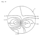
- Fig. 19 shows the astigmatic aberration of a progressive multifocal lens 10 formed such that the original progressive refractive surface 5 and the original toric surface 6 are composed by Composite Equation (5) into a condition nearest to the spherical surface.
- the progressive multifocal lens 10 of this embodiment is designed such that the spherical power S is 0.00D, the cylinder power C is -0.25D, the astigmatic axis is 45°, and the addition Pa is 0.50D, and it shows the astigmatic aberration of the conventional progressive multifocal lens 1 designed under the same conditions as in Fig. 20.
- a progressive multifocal lens 10 can be obtained having an astigmatic aberration substantially equal to that of the conventional progressive multifocal lens 1 and regarding the powers of vision correction and astigmatism correction, a progressive multifocal lens can be obtained having capabilities equal to those of the conventional.
- the progressive multifocal lens 10 of the present embodiment provides to the surface 2 on the side of the eye a curvature demonstrating the functions of a progressive refractive surface 5 and a toric surface 6, the surface 3 on the side of the object can be made such that the base curve is a constant spherical surface. Consequently, the difference in magnification between the distance-vision region and the near-vision region can be made smaller in the same manner as with the embodiments described above. Because the variation in magnification of the progressive region can be made smaller, a comfortable visual field having little jumping and warping of images can be provided to the user.
- a lens 19 formed by simply having added the z coordinates of the original progressive refractive surface and the coordinates of the original toric surface on the surface 2 on the side of the eye is shown in Fig. 21.
- a lens can be provided having the same capabilities as those of the conventional progressive multifocal lens 1. Consequently, because the jumping and warping of images can be reduced using the present invention, a progressive multifocal lens can be provided, being one level more comfortable when worn as an eyeglass lens compared with the conventional progressive multifocal lens.
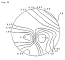
- Fig. 22 shows the astigmatic aberration of a progressive multifocal lens 10 of the present invention formed such that the original progressive refractive surface 5 and the original toric surface 6 are composed by Composite Equation (5) into a condition most deviating from the spherical surface, and it is an example of a progressive multifocal lens of the present invention wherein the variation of the z coordinates of the composite surface 2 on the side of the eye is made greatest.
- the progressive multifocal lens 10 of this embodiment is designed such that the spherical power S is 0.00D, the cylinder power C is -6.00, the astigmatic axis is 45°, and the addition Pa is 3.50D, and it shows the astigmatic aberration of the conventional progressive multifocal lens 1 designed under the same conditions as in Fig. 23.
- a progressive multifocal lens 10 can be obtained having an astigmatic aberration substantially equal to that of the conventional progressive multifocal lens 1.
- Composite Equation (5) of the present invention is effective in composing all ranges of surfaces where the progressive refractive surface 5 has an addition Pa of 0.5-3.5D, and the toric surface 6 has a cylinder power C of 0.25-6.00D. Consequently, by using Composite Equation (5) of the present invention, a progressive multifocal lens can be provided having the progressive refractive surface on the surface 2 on the side of the eye, whereby the jumping and warping of images is improved greatly.
- the progressive multifocal lens of the present invention by placing the progressive refractive surface on the surface on the side of the eye, it becomes possible to depart from the designs in which the surface on the side of the object must be non-spherical, and the surface on the side of the object can be formed such that the base curve is a constant spherical surface. Consequently, because the variation of the magnification MS due to the shape factor Ms caused on the surface on the side of the object can be precluded, it becomes possible to reduce the difference in magnification of the distance-vision region and the near-vision region.
- a progressive multifocal lens can be provided, being able to improve further the jumping and warping of images caused by the difference in magnification between the distance-vision region and the near-vision region.
- a progressive multifocal lens having a high addition of the difference of refractive power of the distance-vision region and the near-vision region by using the progressive multifocal lens of the present invention, the jumping and warping of images can be improved greatly.
- a composite equation is provided that can demonstrate a specified performance by composing the progressive refractive surface and the toric surface for correction of astigmatism on the surface on the side of the eye.
- the jumping and warping of images can be improved, even in a progressive multifocal lens for correction of astigmatism, by providing the progressive refractive surface on the side of the eye. Consequently, it is possible to replace entirely a series of progressive multifocal lenses sold on the market having the progressive refractive surface on the side of the object with a series that have the progressive refractive surface on the side of the eye, and a more comfortable and clearer visual field can be provided for all users.
- the surface on the side of the object can be used freely for any purpose.
- JP-A-2-289818 the fact is disclosed that by using as the convex surface on the side of the object a non-spherical convex surface substantially having the curvature increased at least in the direction of the perimeter from the axis of symmetry in the vicinity of at least the axis of rotational symmetry, the edge thickness of the lens can be made thinner and the astigmatic aberration can be improved. It is possible to use such a convex surface of a rotation axially symmetric non-spherical surface for the convex surface of the progressive multifocal lens of the present invention.
- a non-spherical surface for further improving the optical performance such as astigmatic aberration of a lens, being a fashionable non-spherical surface meeting the user's individuality can be provided on the convex surface on the side of the object.
- a non-spherical surface for the purpose of giving fashion to the optical performance on the convex surface as a progressive multifocal lens. Consequently, by processing the progressive multifocal lens of the present invention into an eyeglass lens, it is possible to provide an eyeglass lens having added fashionable individuality to the optical performance as a progressive multifocal lens.
- the uses of the surface of the eyeglass lens on the side of the object can be broadened variously.
- the present invention relates to a progressive multifocal lens used as an eyeglass lens.
- a progressive multifocal lens can be realized, having little difference of magnification of the distance-vision region and the near-vision region, in addition to the function of correcting aging vision and the function of correcting astigmatism, being equivalent to those of a conventional progressive multifocal lens, and being able to provide a clearer and more comfortable visual field for the user, having the jumping and warping of images reduced greatly.
Abstract
Description
- The present invention relates to a progressive multifocal lens for correction of vision, and a manufacturing method of a progressive multifocal and an eyeglass lens using it.
- A progressive multifocal lens is a lens comprising two field sections having different refractive power, and a field section wherein the refractive power changes progressively between these. It is superior in external appearance, as there are no boundaries in these field sections. Furthermore, fields having different refractive powers in a single lens can be obtained. Therefore, it is used widely as an eyeglass lens having vision correcting functions for aging vision (presbyopia) and the like.
- Fig. 25 shows the general structure of a conventional progressive multifocal lens used widely as an eyeglass lens. This progressive
multifocal lens 1 is provided on the upper side with a distance-vision region 11 being a field section for seeing objects at a far distance. A field section for seeing objects at a near distance having a different refractive power from the distance-vision region 11 is provided on the lower side as a near-vision region 12. The distance-vision region 11 and near-vision region 12 are joined smoothly by aprogressive region 13 being a field section having a refractive power that changes continuously for seeing objects at an intermediate distance between the far distance and the near distance. - In a
single lens 1 used for an eyeglass, all the capabilities required for an eyeglass, for example, a vertex power matching the user's prescription, a cylinder power for correcting astigmatism, an addition power for correcting aging vision, and furthermore a prism power for correcting skew, must be provided by the two surfaces being arefractive surface 2 on the side of the eye and arefractive surface 3 on the side of the observed object. Therefore, in a conventional progressivemultifocal lens 1, as shown in Fig. 25, a progressiverefractive surface 5 providing a refractive power that changes continuously in order to compose the distance-vision region 11, near-vision region 12, andprogressive region 13, is formed on therefractive surface 3 on the side of the object. Therefractive surface 2 is used as a refractive surface, or the like, for correcting astigmatism as described above. - Fig. 26 shows the astigmatism obtained with the conventional progressive
multifocal lens 1, and Fig. 27 shows the summary distribution of the z coordinates of the progressiverefractive surface 5 formed on therefractive surface 3 of the conventional progressive multifocal lens on the side of the object. On therefractive surface 3, the plane surface is represented as the xy coordinates, and the direction showing the thickness of the lens perpendicular to this xy plane is represented as the z coordinates. There is no particular need to define the direction of the x and y coordinates, however, in the following explanation the up-and-down direction when thelens 1 is worn as an eyeglass lens is the y coordinate, and the left-right direction is the x coordinate. - Because the progressive
refractive face 5 is non-spherical so as to change continuously the refractive power, the curvature changes according to each region of the surface. Consequently, as understood from Fig. 26, even in a progressivemultifocal lens 1 not for correction of astigmatism having thesurface 2 on the side of the eye as a spherical surface, if a progressiverefractive surface 5 is introduced on thesurface 3 on the side of the object, an astigmatic aberration is generated on the surface by the difference in curvature in the x direction and the y direction. This astigmatic aberration is represented in diopter (D) units, and the drawing of astigmatic aberration shown in Fig. 26 is a drawing having the regions of specific diopters connected by contour lines. - A user of an eyeglass not having astigmatism can obtain clear vision without perceiving so much the fading of an image if the astigmatic aberration appearing in the lens is 1.0 diopters or less, preferably 0.5 diopters or less. Therefore, a
clear vision region 21 having an astigmatic aberration of 1.0 diopters or less, or preferably 0.5 diopters or less, is placed extending from the distance-vision region to the near-vision region following the main line of sight (umbilical meridian) 14 somewhat bent on the side of the nose, crowding the vision. On this main line ofsight 14, in particular, an astigmatic aberration is not generated by substantially eliminating the difference in curvature in the x direction and in the y direction. Consequently, the astigmatic aberration appears greater because thelens 1 becomes non-spherical in the direction of the perimeter from the main line ofsight 14. - Furthermore, if such an astigmatic aberration changes greatly, it becomes a cause of discomfort as the image jumps following the line of sight when the user moves the line of sight. Therefore, in the distance-
vision region 11 having great movement of the line of sight, it is set such that the astigmatic aberration does not change so much. The design of a progressiverefractive surface 5 is made such that the astigmatic aberration does not change greatly in the other regions as well. Aneyeglass lens 9 is formed by "globe processing", i.e. processing the outer shape of thelens 1 into a shape matching the eyeglass frame, and is provided to the user. - The
lens 1 shown in Fig. 26 and Fig. 27 is a lens wherein the base curve Pb, showing the fundamental refractive power of thesurface 3 on the side of the object having the progressiverefractive surface 5 applied, is 4.00D, the addition Pa is 2.00D, the surface refractive power D2 of thesurface 2 on the side of the eye is 6.00D, the center thickness t of the lens is 3.0mm, and the diameter d of the lens is 70.0mm. - Fig. 28 shows a conventional progressive
multifocal lens 1 for astigmatism wherein atoric surface 6 having a cylinder power C for correcting astigmatism is formed on thesurface 2 on the side of the eye. Fig. 29 shows a drawing of the astigmatic aberration of this lens. Fig. 30 shows the z coordinates of thetoric surface 6. The lens showing astigmatic aberration in Fig. 29 has a cylinder power C of -2.00D. The other conditions are identical to the lens showing astigmatic aberration in Fig. 26. This progressivemultifocal lens 1 for astigmatism has an astigmatic aberration of 2.00D introduced substantially uniformly in order to correct the astigmatism following the main line ofsight 14. Aneyeglass lens 9 can be formed by globe processing according to the eyeglass frame identically to that mentioned above. - Thus, an eyeglass lens is sold on the market that corrects astigmatism, wherein the refractive power changes continuously from the distance-vision region to the near-vision region using a progressive refractive surface, and it is used widely as a means to correct vision. If the progressive multifocal lens has a high prescription to become a measure for correction of vision, and if the addition, being the difference in refractive power between the distance-vision region and the near-vision region, is great, the astigmatic aberration appearing in the lens also becomes great because the progressive refractive surface is made further non-spherical.
- Therefore, it is possible to provide the user with a comfortable visual field by improving the shape of the progressive refractive surface, and removing the astigmatic aberration from the commonly used regions of the lens, preventing a dramatic change in astigmatic aberration. Jumping and warping of images can be improved by suppressing the variation of astigmatic aberration. However, in a progressive multifocal lens, jumping and warping of images are also caused by differences in refractive power between the distance-vision region and the near-vision region. That is, the distance-
vision region 11 has a refractive power whereby the focus is at a distance, while the near-vision region 12 has a refractive power different from that of the distance-vision region 11 whereby the focus is near. Consequently, in theprogressive region 13, because the magnification gradually varies, this is one main reason why the acquired images jump and are distorted. - In the design of a progressive refractive surface, all kinds of proposals already have been tried. Also, designs using the computational powers of computers have been tried as well. The suppression of jumping and warping of images by improving the astigmatic aberration of the progressive refractive surface is considered to have nearly reached its limit. Thus, in the present invention, the aim is to provide a progressive multifocal lens capable of improving the jumping and warping of images caused by variation of the magnification between the distance-vision region and the near-vision region of the progressive multifocal lens.
- The aim is to provide a progressive multifocal lens and eyeglass lens that can reduce more greatly the jumping and warping of images while approaching the limits in the design of the progressive refractive surface, and that can provide a more comfortable visual field to the user. Also, the aim is to provide a progressive multifocal lens and eyeglass lens that can provide clear vision having little jumping and warping even for users having a great difference in prescription (addition between the distance-vision region and the near-vision region, which easily generates jumping and warping of images.
- Therefore, the inventors of the present invention have focused on the placement of the progressive refractive surface contributing to magnification of a progressive multifocal lens, and have discovered that it is possible to reduce the difference of magnification between the distance-vision region and the near-vision region by introducing the progressive refractive surface on the side of the eye. That is, the present invention is a progressive multifocal lens for correction of vision, comprising a distance-vision region and a near-vision region having different refractive power, and a progressive region wherein the refractive power between these changes progressively, wherein a curvature of the progressive surface for composing the distance-vision region, near-vision region, and progressive region are provided on the surface of the progressive multifocal lens on the side of the eye.
- The lens magnification SM generally is represented by the following equation.

- Here, Mp is the power factor. Ms is called the shape factor. As shown in Fig. 1, the distance from the vertex (internal vertex) of the surface of the lens on the side of the eye to the eye is represented below as L, the refractive power of the internal vertex (internal vertex power) as Po, the center thickness of the lens as t, the refractivity of the lens as n, the base curve (refractive power) of the surface of the lens on the side of the object as Pb.

- In the computations of Equations (2) and (3), diopters (D) is used regarding the internal vertex power Po and the base curve Pb, and meters (m) is used regarding the distance L and thickness t.
- The internal vertex power Po contributes to the correction of vision in the distance-vision region and the near-vision region, and it is understood that, for maintaining the internal vertex power of a required value, the variation of the magnification SM can be controlled by suppressing the variation of the base curve Pb of the surface on the side of the object. For example, if the base curve Pb of the convex surface on the side of the object is made constant, the variation of the magnification MS due to the shape factor Ms can be eliminated.
- Nevertheless, as shown by the broken line in Fig. 1, when the progressive refractive surface is provided on the surface on the side of the object, the base curve Pb on the side of the object cannot be made constant. Furthermore, the variation of the shape factor Ms becomes greater as the addition becomes greater. Jumping and warping of images increases. Thus, in the present invention, it is made possible to suppress the variation of the base curve Pb of the surface on the side of the object, as shown by the solid line in Fig. 1, by introducing the progressive refractive surface into the concave surface on the side of the eye, and to provide a spherical progressive multifocal lens having, for example, a constant base curve.
- Consequently, in the progressive multifocal lens of the present invention, the difference in magnification between the distance-vision region and the near-vision region can be held to a necessary minimum. Because the variation of the magnification in the progressive region can be suppressed as well, even if the performance according to the distortion of images is the same extent as a conventional progressive multifocal lens, a progressive multifocal lens and eyeglass lens can be provided whereby the jumping and warping of images is reduced, and a more comfortable visual field can be provided to the user. Particularly, in a progressive multifocal lens having a great addition, the jumping and warping can be reduced.
- Fig. 2 compares the magnification achieved by a progressive multifocal lens of the present invention having a base curve Pd of 5.00D, an addition of 3.00D, a spherical power S of 2.00D, a refractivity n of 1.662, and a distance L of 15.0mm as an example, and the magnification achieved by a conventional progressive multifocal lens having the progressive refractive surface on the side of the object. As is clear from this drawing, in the progressive multifocal lens of the present invention, the difference in magnification between the distance-vision region and the near-vision region can be suppressed to 80% of the conventional difference of magnification. Jumping and warping of images are prevented to a great degree.
- Furthermore, as shown in Fig. 3, this effect becomes prominent as the addition Pa becomes greater. Fig. 3 shows, as an example, the difference of magnification between the distance-vision region and the near-vision region of a progressive multifocal lens pertaining to the present invention having a progressive refractive surface on the surface (concave surface) on the side of the eye, wherein the base curve Pd for the above-mentioned lens is 4.00D, and the spherical power S is 0.00D. To be compared with this, the difference of magnification between the distance-vision region and the near-vision region of a conventional progressive multifocal lens having the progressive refractive surface on the surface (convex surface) on the side of the object is shown.
- As is clear from this drawing, in the progressive multifocal lens of the present invention, it is possible to use the same extent of difference of magnification as that of a conventional progressive multifocal lens having a higher addition Pa from
rank 1 at a low addition power region to rank 2 at a high addition power region (whererank 1 corresponds to 0.25D,rank 2 corresponds to 0,50D etc.). As a result, the jumping and warping of images perceived by the user also can be suppressed to the same extent as aconventional rank 1 orrank 2 addition lens. - In the progressive multifocal lens of the present invention, because the curvature of the progressive refractive surface is provided to the surface on the side of the eye, the curvature of the progressive refractive surface (reciprocal of the radius of curvature) following the main line of sight becomes smaller in the near-vision region compared with the distance-vision region.
- Also, in the distance-vision region, the curvature of the progressive refractive surface becomes smaller in at least one region as it departs from the main line of sight. Also, in the near-vision region, the curvature of the progressive refractive surface becomes greater in at least on region as it departs from the main line of sight.
- It is possible to make a progressive multifocal lens having an addition in the range of 0.5-3.5 to correspond to a wide range of users, from users having almost no advance of aging vision to users having advanced aging vision where the power to accommodate is almost entirely lost. As shown in Fig. 3, it is clear that a great effect can be achieved in the improvement of jumping and warping of images in a progressive multifocal lens of the present invention within this range.
- When the surface of the progressive multifocal lens of the present invention is a rotationally symmetric surface, this range of addition is expressed as follows using the average surface refractive power D1 on the side of the eye in the vicinity of the main line of sight of the distance-vision region, and the average surface refractive power D2 on the side of the eye in the vicinity of the main line of sight of the near-vision region.

- Furthermore, as a progressive refractive surface, it is desirable to minimize the astigmatic aberration when forming the progressive refractive surface on the main line of sight. Therefore, it is desirable that the curvature of the progressive refractive surface have the curvature of two orthogonal directions be equal in at least one region of the main line of sight.
- In the progressive multifocal lens of the present invention, because the progressive refractive surface is provided on the surface on the side of the eye, a progressive multifocal lens for correction of astigmatism wherein the surface on the side of the eye has the astigmatism correcting properties can be provided by applying the curvature of an astigmatism correcting toric surface to the surface on the side of the eye. That is, the surface on the side of the eye is the progressive refractive surface. Furthermore, a progressive multifocal lens having cylinder power can be provided.
- Also, by using as an eyeglass lens the progressive multifocal lens having astigmatism correcting properties of the present invention, the difference of magnification between the distance-vision region and the near-vision region can be held to a minimum as described above, and a more comfortable visual field can also be provided to a user having astigmatism, there being little warping and jumping of images in addition to being able to correct astigmatism.
- A progressive multifocal lens having vision correcting properties and astigmatism correcting properties applied to the surface on the side of the eye can be manufactured by a manufacturing method comprising a first process that determines a progressive refractive surface (henceforth, original progressive refractive surface) only for the purpose that the surface on the side of the eye demonstrates the desired vision correcting properties, a second process that determines a toric surface (henceforth, original toric surface) only for the purpose that the surface on the side of the eye demonstrates the intended astigmatism correcting properties, and a third process that determines the surface of the progressive multifocal lens on the side of eye from the original progressive refractive surface and the original toric surface. By introducing to the surface on the side of the eye a progressive refractive surface wherein the original progressive refractive surface and the original toric surface are composed, a progressive multifocal lens can be realized, having both functions being an astigmatism correcting function using the toric surface and a vision correcting function for correction other than astigmatism using the progressive refractive surface, and furthermore, having little jumping and warping.
- In the third process described above, it is possible to compose a progressive refractive surface having astigmatism correcting properties by adding the z coordinates composing the original progressive refractive surface having the vision correcting properties to the values of the z coordinates for composing the original toric surface having the astigmatism correcting properties. Nevertheless, according to the results of examination by the present inventors, in order to achieve an astigmatism correcting function (astigmatic aberration property) being equal to that of a conventional progressive multifocal lens for correction of astigmatism wherein the side of the object is the progressive refractive surface and the side of the eye is the toric surface, it is desirable that the progressive refractive surface be composed using a composite equation such as shown in the following Equation (5).
- That is, in the third process, by seeking the value at any point p (X, Y, Z) of the surface of the progressive multifocal lens on the side of the eye by the following Equation (5) using the approximate curvature Cp of the original progressive refractive surface, the curvature Cx of the original toric surface in the x direction, and the curvature Cy in the y direction, a progressive multifocal lens for correction of astigmatism can be provided having an astigmatism correcting capability and a vision correcting function equal to the conventional progressive multifocal lens and, furthermore, having a small difference in magnification and improved jumping and warping.

- Here, while the eyeglass is being worn, when the axis passing through the center of the progressive refractive surface from the side of the object to the side of the eye is taken as the z axis, the axis orthogonal to the z axis oriented from bottom to top as the y axis, and the axis orthogonal to the z axis oriented from left to right as the x axis. X and Y indicate arbitrary points on the x and y coordinates, respectively, on the surface on the side of the eye, and Z indicates the z coordinate in the perpendicular direction of the surface on the side of the eye. Curvature Cp is the approximate curvature at any point p (X, Y, Z) of the original progressive refractive surface, curvature Cx is the curvature in the x direction of the toric surface for correction of astigmatism, and curvature Cy is the curvature in the y direction.
- In the present example, the average curvature of the radial direction is used as the approximate curvature Cp, and the reciprocals of the circular radius passing through the three points in the xy plane perpendicular to the z axis (passing through the center of the lens or the internal vertex (0, 0, 0)), including any point p (X, Y, Z) on the original refractive surface, the point p' (-X, -Y, Z) rotationally symmetric with point p, and the internal vertex (0, 0, 0) are used. However, when the point p on the original progressive refractive surface is positioned at the internal vertex, the average curvature in the radial direction Cp is not defined, and Z = 0 in Equation (5).
- In the present invention, by using such a Composite Equation (5), it is possible to apply the properties of the original progressive refractive surface and the original toric surface. Consequently, a progressive multifocal lens for correction of vision on the side of the eye, and furthermore, a progressive multifocal lens comprising a progressive refractive surface on the side of the eye, having both vision correcting and astigmatism correcting properties, can be provided, and an eyeglass lens for a wide range of users covering a range from users not having astigmatism to users requiring correction of astigmatism can be realized. Therefore, it becomes possible to provide to the market eyeglass lenses having little jumping and warping using a series of progressive multifocal lenses for all users.
- By applying a 270° base prism on a progressive multifocal lens having a progressive refractive surface on the side of the eye, the progressive multifocal lens can be made lightweight. By setting the vertex power Ps of the distance-vision region, the addition power Pa, and the refractive power (base curve) of the surface of the progressive multifocal lens on the side of the object such that they satisfy the following equation, a progressive multifocal lens of the present invention can be provided, having a progressive refractive surface on the side of the eye as a meniscus applied to an eyeglass lens.

-
- Fig. 1
- is an explanatory drawing showing an overview of a progressive multifocal lens of the present invention.
- Fig. 2
- is a drawing showing the magnification of the distance-vision region, the magnification of the near-vision region, and the difference in magnification between the distance-vision region and the near-vision region of a progressive multifocal lens of the present invention as an example, compared with a conventional progressive multifocal lens.
- Fig. 3
- is a drawing showing the relationship between the difference in magnification between the distance-vision region and the near-vision region and the addition of a progressive multifocal lens of the present invention as an example, compared with a conventional progressive multifocal lens.
- Fig. 4
- is a drawing showing an overview of a progressive multifocal lens pertaining to
Embodiment 1 of the present invention. Fig. 4(a) is a front view drawing, and Fig. 4(b) is a cross-section drawing following the main line of sight. - Fig. 5
- is a drawing showing the astigmatic aberration of the progressive multifocal lens shown in Fig. 4.
- Fig. 6
- is a drawing showing the z coordinates of the surface on the side of the eye of the progressive multifocal lens shown in Fig. 4.
- Fig. 7
- is a drawing showing the radius of curvature (reciprocal of curvature) of the surface on the side of the eye following the main line of sight of the progressive multifocal lens shown in Fig. 4.
- Fig. 8
- is a drawing showing the radii of curvature of the surface on the side of the eye in the direction orthogonal to the main line of sight of the progressive multifocal lens shown in Fig. 4. Fig. 8(a) is a drawing showing the radius of curvature of the distance-vision region, and Fig. 8(b) is a drawing showing the radius of curvature of the near-vision region.
- Fig. 9
- is a drawing showing the manner of applying a 270° base prism to the progressive multifocal lens shown in Fig. 4. Fig. 9(a) is a cross-section of a progressive multifocal lens being an example not having the prism applied, and Fig. 9(b) is a cross-section of a progressive multifocal lens being an example having the prism applied.
- Fig. 10
- is a drawing showing an overview of a progressive multifocal lens pertaining to
Embodiment 2 of the present invention. Fig. 10(a) is a front view drawing, and Fig. 10(b) is a cross-section drawing following the main line of sight. - Fig. 11
- is a drawing showing the astigmatic aberration of the progressive multifocal lens shown in Fig. 10.
- Fig. 12
- is a drawing showing the z coordinates of the surface on the side of the eye of the progressive multifocal lens shown in Fig. 10.
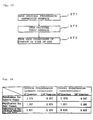
- Fig. 13
- is a flow chart showing the manufacturing process of a progressive multifocal lens of the present invention having a vision correcting capability and an astigmatism correcting capability.
- Fig. 14
- is a drawing showing the difference an magnification between the distance-vision region and the near-vision region of a progressive multifocal lens of the present invention having a vision correcting capability and an astigmatism correcting capability as an example, compared with a conventional progressive multifocal lens.
- Fig. 15
- is a drawing showing an overview of a lens having added the original progressive refractive surface and the original toric surface in
Embodiment 2 of the present invention. Fig. 15(a) is a front view drawing, and Fig. 15(b) is a cross-section drawing following the main line of sight. - Fig. 16
- is a drawing showing the astigmatic aberration of the lens shown in Fig. 15.
- Fig. 17
- is a drawing showing the z coordinates of the surface on the side of the eye of the lens shown in Fig. 15.
- Fig. 18
- is a graph showing the variation of astigmatic aberration following the main line of sight of the progressive multifocal lens of
Embodiment 2 of the present invention shown in Fig. 10, along with the same of the conventional progressive multifocal lens shown in Fig. 28 and the lens shown in Fig. 15. - Fig. 19
- is a drawing showing the astigmatic aberration of a progressive multifocal lens of another embodiment of the present invention.
- Fig. 20
- is a drawing showing the astigmatic aberration of a conventional progressive multifocal lens corresponding to the progressive multifocal lens shown in Fig. 19.
- Fig. 21
- is a drawing showing the astigmatic aberration of a progressive multifocal lens formed without using the composite equation corresponding to Fig. 19.
- Fig. 22
- is a drawing showing the astigmatic aberration of a progressive multifocal lens of another embodiment of the present invention.
- Fig. 23
- is a drawing showing the astigmatic aberration of a conventional progressive multifocal lens corresponding to the progressive multifocal lens shown in Fig. 22.
- Fig. 24
- is a drawing showing the astigmatic aberration of a progressive multifocal lens formed without using the composite equation corresponding to Fig. 22.
- Fig. 25
- is a drawing showing an overview of a conventional progressive multifocal lens. Fig. 25(a) is a front view drawing and Fig. 25(b) is a cross-section drawing following the main line of sight.
- Fig. 26
- is a drawing showing the astigmatic aberration of the progressive multifocal lens shown in Fig. 25.
- Fig. 27
- is a drawing showing the z coordinates of the progressive refractive surface on the side of the object of the progressive multifocal lens shown in Fig. 25.
- Fig. 28
- is a drawing showing an overview of a conventional progressive multifocal lens for correction of astigmatism. Fig. 28(a) is a front view drawing, and Fig. 28(b) is a cross-section drawing following the main line of sight.
- Fig. 29
- is a drawing showing the astigmatic aberration of the progressive multifocal lens shown in Fig. 28.
- Fig. 30
- is a drawing showing the z coordinates of the toric surface on the side of the eye of the progressive multifocal lens shown in Fig. 28.
- The present invention is explained in further detail below based on several progressive multifocal lenses designed based on the present invention.
- Fig. 4 shows a progressive
multifocal lens 10 of the present invention having a progressiverefractive surface 5 on thesurface 2 on the side of the eye. In the same manner as the conventional progressive multifocal lens shown in Fig. 25, the progressivemultifocal lens 10 of the present embodiment is provided with a distance-vision region 11 on the upper side, being a vision section for seeing objects at far distances, and a vision section for seeing objects at close distances having a refractive power different from the distance-vision region 11 is provided on the lower side as a near-vision region 12. Furthermore, the distance-vision region 11 and the near-vision region 12 are joined smoothly by aprogressive region 13 wherein the refractive power varies continuously. - The progressive
multifocal lens 10 of the present embodiment has a non-spherical progressiverefractive surface 5 on thesurface 2 on the side of the eye to form the distance-vision region 11, the near-vision region 12, and theprogressive region 13. Therefore, thesurface 3 on the side of the object can be formed spherically whereby the base curve Pd becomes constant. Consequently, as explained using Equations (1)-(3) above, the difference in magnification between the distance-vision region 11 and the near-vision region 12 becomes smaller, and the rate by which the magnification changes in theprogressive region 13 can be made smaller. Consequently, compared with a conventional progressive multifocal lens having a progressive refractive surface on the side of the object, the jumping and distortion of images caused by the difference in magnification can be reduced to a great extent. - Fig. 5 and Fig. 6 show the astigmatic aberration of a progressive
multifocal lens 10 of the present invention having a progressive refractive surface on thesurface 2 on the side of the eye, and the z coordinates of thesurface 2 on the side of the eye, that is, the progressiverefractive surface 5. The progressivemultifocal lens 10 of the present embodiment is designed such that the same degree of astigmatic aberration can be obtained as with a conventional progressive multifocal lens having the progressive refractive surface on thesurface 3 on the side of the object. - The progressive
multifocal lens 10 shown in Fig. 5 and Fig. 6 has aspherical surface 3 on the side of the object, and the base curve Pb indicating its refractive power is a constant at 4.00D. Regarding thesurface 2 on the side of the eye, the average surface refractive power of the distance-vision region 11 is set to 6.00D, the average surface refractive power of the near-vision region 12 to 4.00D, the addition Pa to 2.00D. The spherical power S of the distance-vision region is -2.00D, the center thickness of the lens is 3.0mm, and the lens diameter d is 70.0mm. Under such conditions, a progressiverefractive surface 5 such as shown in Fig. 4 can be provided to thesurface 2 on the side of the eye. As a result, a progressivemultifocal lens 10 can be obtained, having an astigmatic aberration such as shown in Fig. 5. - The astigmatic aberration of the progressive
multifocal lens 10 of the present embodiment shown in Fig. 5 is substantially the same as the astigmatic aberration of the conventional progressive multifocal lens shown in Fig. 26. Regarding the astigmatic aberration, it is clear that a progressivemultifocal lens 10 can be realized, having the identical performance as a conventional progressive multifocal lens having the progressive refractive surface provided on thesurface 3 on the side of the object, even when the progressiverefractive surface 5 is provided on thesurface 2 on the side of the eye. - Consequently, regarding the astigmatic aberration, the progressive
multifocal lens 10 of the present embodiment is a progressive multifocal lens having the identical properties as conventionally, whereby a clear vision region is secured sufficiently, and having little distortion and jumping of images caused by variation of the astigmatic aberration. Furthermore, in the progressivemultifocal lens 10 of the present embodiment, when comparing the difference of magnification between the distance-vision region 11 and the near-vision region 12, the magnification of the distance-vision region is 0.976, the magnification of the near-vision region is 1.007, and their difference is 0.031. - As opposed to this, in the
conventional lens 1 having the progressive refractive surface provided on the side of the object, the magnification of the distance-vision region is 0.976, the magnification of the near-vision region is 1.011, and their difference is 0.035. Consequently, it is clear that in the progressivemultifocal lens 10 of the present embodiment, the difference of magnification between near and far can be improved as much as 12-13% over the conventional. - By this difference in magnification being reduced in this manner, in the progressive
multifocal lens 10 of the present embodiment, the jumping and distortion of images caused in a progressive multifocal lens by the difference in magnification can be improved further. Therefore, aneyeglass lens 9 that is clearer, whereby the jumping and distortion are improved greatly, can be provided by globe processing the progressivemultifocal lens 10 of the present embodiment to match the eyeglass frame. - The progressive
refractive surface 5 of the present embodiment provided on thesurface 2 on the side of the eye is explained further. Fig. 7 shows the variation of the radius of curvature of the progressiverefractive surface 5 following the main line ofsight 14. The z coordinates of this drawing have the direction of the viewed object set to negative, and the direction of the eye set to positive. In a progressive multifocal lens for an eyeglass, the value of the refractive power of the distance-vision region 11 is smaller than the value of the refractive power of the near-vision region 12, that is, they are set such that it becomes negative when the value of the refractive power of the near-vision region is subtracted from the value of the refractive power of the distance-vision region 11. Therefore, among the radii of curvature of the progressiverefractive surface 5 following the main line ofsight 14, if the radius of curvature forming the upper distance-vision region 11 is r1, and the radius of curvature forming the near-vision region 12 is r2, the radius of curvature r1 of the progressivemultifocal lens 10 of the present embodiment is smaller than the radius of curvature r2. Consequently, if the respective radii of curvature r1 and r2 are represented by the reciprocal curvatures C1 and C2, the curvature C1 of the distance-vision region 11 and the curvature C2 of the near-vision region 12 must satisfy the following relationship.
- As shown in Fig. 8(a), because the radius of curvature of the distance-
vision region 11 in the direction orthogonal to the main line ofsight 14 forms aprogressive region 13 continuously with the near-vision region 12 having a large radius of curvature, a region that becomes larger following movement away from the main line ofsight 14 is provided. On the other hand, as shown in Fig. 8(b), because the radius of curvature of the near-vision region 12 in the direction orthogonal to the main line ofsight 14 forms aprogressive region 13 continuously with the distance-vision region 11 having a small radius of curvature, a region that becomes smaller following movement away from the main line ofsight 14 is provided. - That is, in the
direction 15 of the distance-vision region 11 orthogonal to the main line ofsight 14, if r3 is the radius of curvature in the vicinity of the main line ofsight 14, and r4 is the radius of curvature of the region remote from the main line ofsight 14 namely in or beyond a range of 5-35mm, r3 becomes the same as r4 or less. If r3 and r4 are represented by their reciprocal curvatures C3 and C4, in the distance-vision region 11, the curvature C4 of the region remote from the main line ofsight 14 in relation to the curvature C3 in the vicinity of the main line ofsight 14 satisfies the following relationship.
- Of course, it is possible to secure a wide clear-vision region in the distance-
vision region 11 by making thesurface 2 on the side of the eye composing the distance-vision region 11 as a spherical surface, as well as to concentrate theprogressive region 13 in the vicinity of the near-vision region 12. In this case, in the distance-vision region 11, the curvature C3 and the curvature C4 become equal. - Meanwhile, in the
direction 16 of the near-vision region 12 orthogonal to the main line ofsight 14, if r5 is the curvature in the vicinity of the main line ofsight 14, and r6 is the curvature of the region removed from the main line ofsight 14 by a range of 5-35mm, r5 becomes the same as r6 or more. Consequently, if r5 and r6 are represented by their reciprocal curvatures C5 and C6, in the near-vision region 12, the curvature C6 of the region removed from the main line ofsight 14 in relation to the curvature C5 in the vicinity of the main line ofsight 14 satisfies the following relationship.
- In the near-
vision region 12 as well, it is possible to secure a wide clear-vision region by making thesurface 2 on the side of the eye composing the near-vision region 12 as a spherical surface, as well as to concentrate theprogressive region 13 in the vicinity of the distance-vision region 11. In this case, in the near-vision region 12, the curvature C5 and the curvature C6 become equal. - As for the variation of the radii of curvature of the above-mentioned Equations (8) and (9) oriented laterally in relation to the main line of
sight 14, the curvatures in thedirections sight 14 have been explained as examples. However, there is no strict limitation regarding direction in particular, and it is acceptable as long as the average curvatures satisfy the above-mentioned Equations (8) and (9) as they are distanced from the main line ofsight 14. - When the
eyeglass lens 9 of the present embodiment is worn by the user, there is much eye movement along the main line ofsight 14. Therefore, in a progressivemultifocal lens 10 not requiring correction of astigmatism, it is desirable that the main line ofsight 14 be composed by an aggregation of the umbilical points in order to prevent jumping and warping of the images. Consequently, the following relationships arise among the various curvatures C1, C2, C3, and C5 described above.
- At this time, the average surface refractive power D1 of the
surface 2 of the distance-vision region 11 on the side of the eye following the main line of sight, and the average surface refractive power D2 of thesurface 2 of the near-vision region 12 on the side of the eye are represented by the following equations:
- Here, n is the refractivity of the lens material composing the progressive
multifocal lens 10 of the present embodiment. - Because the progressive
multifocal lens 10 of the present embodiment has thesurface 3 on the side of the object formed as a spherical surface, the addition Pd can be represented by the difference between the average surface refractive power D1 of the distance-vision region 11 and the average surface refractive power D2 of the near-vision region 12. Furthermore, because the curvature C1 of the distance-vision region 11 is greater than the curvature C2 of the near-vision region 12, as shown in Equation (7), in thesurface 2 on the side of the eye, the average surface refractive power D1 of the distance-vision region 11 becomes greater than the average surface refractive power D2 of the near-vision region 12. - As explained above based on Fig. 3, by using the progressive
multifocal lens 10 of the present invention, the difference in magnification between the distance-vision region 11 and the near-vision region 12 can be reduced for a wide range of progressive multifocal lenses from a progressive multifocal lens having an addition of 3.5 diopters for users having substantially no power of accommodation to a progressive multifocal lens having an addition of 0.5 diopters when aging vision is not substantially advanced, and a comfortable visual field can be provided to the user by suppressing the jumping and warping of images. - For example, even for a user having entirely no power of accommodation, if it is 3.50 diopters, a distance from an infinite distance to approximately 30cm can be seen clearly. If this range of additions is shown using the average surface refractive powers D1 and D2 of the distance-
vision region 11 and the near-vision region 12, it becomes the following Equation (4) as explained above.
- When a toric surface is applied to the
surface 2 on the side of the eye in order to perform correction of astigmatism, the main line ofsight 14 does not become an aggregate of umbilical points, as shown in the next embodiment, and a substantially uniform astigmatic aberration is applied to the main line ofsight 14 in order to correct the astigmatism. - As disclosed in detail in JP-A-2-39768, when directionality occurs in the refractive power for reasons such as making the eyeglass lens more lightweight and standardized, it is desirable that the astigmatic aberration due to the difference in curvature be generated in a direction that cancels the astigmatic aberration due to the refractive power. Consequently, in such a case, it is desirable that differences be provided for the curvatures C1 and C2 following the main line of
sight 14 and the curvatures C3 and C5 of the directions orthogonal to these. - In the progressive
multifocal lens 10 of the present embodiment having a progressiverefractive surface 5 on thesurface 2 on the side of the eye, moving toward the perimeter of the lens, the refractive power Pt following the main line ofsight 14 becomes such that a degree is obtained generally being more positive than the refractive power Ps in the orthogonal direction. Consequently, in such a case, in order that the astigmatic aberration be canceled by the refractive powers Pt and Ps, as shown in the following Equation (12), it is desirable that the curvatures C1 and C2 following the main line ofsight 14 be rather larger than the curvatures C3 and C5 in the orthogonal directions.
- As shown in Fig. 9(a), because the progressive
multifocal lens 10 of the present embodiment has thesurface 2 on the side of the eye as the progressiverefractive surface 5, the lens of the distance-vision region 11 becomes thicker than that of the near-vision region 12. Consequently, in order to make the progressivemultifocal lens 10 thinner and lighter, it is desirable that a 270° base prism be applied not for the purpose of correction of vision. By this, an extremely thin progressivemultifocal lens 10 can be realized as shown in Fig. 9(b). The direction of the prism base is represented as the counter-clockwise angle based on a horizontal line, seeing the direction in which a light beam introduced perpendicularly to thesurface 2 of the lens on the side of the eye inclines due to the prism effect, from thesurface 3 on the side of the object. For the amount of prism effect applied at this time, the optimal value for the user can be selected between 0.25-3.00 prism diopters. - In the progressive
multifocal lens 10 of the present embodiment, because thesurface 3 on the side of the object being suitable for an eyeglass lens is convex, and thesurface 2 on the side of the eye is concave, the internal vertex power (vertex power) Ps of the distance-vision region 11, the addition power Pa, and the refractive power (base curve) Pb of thesurface 2 the progressive multifocal lens on the side of the object must be set so as to satisfy the following Equation (6) described above.
- By selecting the vertex power Ps, addition Pa, and base curve Pb so as to satisfy this Equation (6), it can be made as a meniscus-shaped progressive
multifocal lens 10, and an eyeglass lens fitting the face can be provided. - Fig. 10 shows a progressive
multifocal lens 10 having the properties of a progressive refractive surface and a toric surface provided on the surface of the present invention on the side of the eye. In the following, in order to be distinguished from the progressive refractive surface of the present embodiment having both functions of vision correcting properties and astigmatism correcting properties formed on thesurface 2 on the side of the eye, the progressive refractive surface established only for the purpose that the surface on the side of the eye demonstrate the desired vision correcting properties is called the original progressive refractive surface, and the toric surface established only for the purpose that the surface on the side of the eye demonstrate the intended astigmatism correcting properties is called the original toric surface - The progressive
multifocal lens 10 of the present embodiment is designed and manufactured by a procedure shown using the flow chart in Fig. 13. First, in step ST1, the original progressive refractive surface is sought by parameters meeting the conditions of the user such as the extent of aging vision and the method of using eyeglasses, and that result is recorded as coordinates or curvatures, or the like. Before and after this, in step ST2, the original toric surface for correcting the user's astigmatism is sought, and that result is recorded as curvatures. Of course, it may be recorded also as coordinates. - In step ST3, all the coordinates of the surface on the side of the eye having the vision correcting and astigmatism correcting properties are sought using the results of step ST1 and ST2. In the present embodiment, in step ST3, the values Z of the z coordinates of the
surface 2 on the side of the eye are sought using the following Composite Equation (5) as described above.
- By using this Composite Equation (5), a progressive multifocal lens can be provided, having a function that performs correction of astigmatism for correction of vision, just as with the conventional progressive multifocal lens shown in Fig. 28.
- Fig. 11 shows a drawing of the astigmatic aberration of the progressive
multifocal lens 10 of the present invention, corresponding to the conventional progressive multifocal lens shown in Fig. 29, having progressive refractive surface on thesurface 3 on the side of the object, and a toric surface on thesurface 2 on the side of the eye. - Fig. 12 shows the values of the z coordinates of the progressive
multifocal lens 10 of the present embodiment. By composing the original progressiverefractive surface 5 shown in Fig. 6 and the originaltoric surface 6 shown in Fig. 30 using the above Equation (5), asurface 2 on the side of the eye can be composed, having the values Z of the z coordinates such as shown in Fig. 12. - The progressive
multifocal lens 10 of the present invention is formed using thissurface 2 on the side of the eye and aspherical surface 3 on the side of the object, and a progressive multifocal lens for correction of astigmatism such as shown in Fig. 11 can be obtained, having substantially identical astigmatic aberration as that of Fig. 29. Consequently, according to the present invention, a progressivemultifocal lens 10 can be obtained, having the equivalent vision correcting power and astigmatism correcting power as the conventional progressive multifocal lens having the progressive refractive surface on thesurface 3 on the side of the object and the toric surface on thesurface 2 on the side of the eye. - Thus, in the present embodiment, the curvature of a toric surface for correction of astigmatism can be applied to the surface on the side of the eye in addition to the curvature of a progressive refractive surface for correction of vision, and it can be made such that the surface on the side of the eye has an astigmatism correcting property, that is, a cylinder power. Consequently, because a progressive refractive surface having vision correcting power and astigmatism correcting power can be prepared on the side of the eye, in addition to the vision correcting power and the astigmatism correcting power, the difference in magnification between the distance-
vision region 11 and the near-vision region 12 can be made less, and a progressivemultifocal lens 10 can be provided, whereby the jumping and warping of images is improved. - As shown in Fig. 14, when the difference in magnification between near and far of the progressive
multifocal lens 10 of the present embodiment is compared with a conventional lens, it can be improved by 12-13% in either the 90° direction or the 180° direction, and according to the present invention, it is clear that jumping and warping can be reduced even in a progressive multifocal lens for correction of astigmatism. Consequently, by globe processing the progressivemultifocal lens 10 of the present embodiment according to the eyeglass frame, it becomes possible to provide aneyeglass lens 9 capable of correcting vision and astigmatism, and having extremely little jumping and warping of images. Therefore, according to theeyeglass lens 9 of the present invention, a comfortable visual field can be provided even for users having astigmatism. - For the progressive
multifocal lenses 10 in Fig. 11 and Fig. 12, the base curve Pb indicating the refractive power of thesurface 3 on the side of the object is a constant 4.00D. For thesurface 2 on the side of the eye, the same as withEmbodiment 1, the average surface refractive power of the distance-vision region 11 is set to 6.00D, the average surface refractive power of the near-vision region 12 is set to 4.00D, and the addition Pa is set to 2.00D. In addition to this, a toric surface is composed, having an astigmatic axis of 90°, a spherical power S of -2.00D, and a cylinder power C of -2.00D. The center thickness t of the lens is 3.0mm, and the lens diameter d is 70.0mm. - Fig. 15 shows a
lens 19 having a progressive refractive surface having formed asurface 2 on the side of the eye by adding the values of the z coordinates of the original toric surface shown in Fig. 30 to the values of the z coordinates of the original progressive refractive surface shown in Fig. 6 instead of using Composite Equation (5) mentioned above. - Fig. 16 shows a drawing of the astigmatic aberration of the
lens 19, and Fig. 17 shows the z coordinates of thesurface 2 of thelens 19 on the side of the eye. A progressive refractive surface can be formed, having vision correcting properties and astigmatism correcting properties by adding the values of the z coordinates of the original toric surface to the values of the z coordinates of the original progressive refractive surface. Nevertheless, as is clear from Fig. 16, when Composite Equation (5) described above is not used, it is clear that it is difficult to achieve an astigmatic aberration equivalent to that of the conventional progressive multifocal lens shown in Fig. 29, and it is difficult to achieve vision correcting and astigmatism correcting powers exactly equal to those of the conventional progressive multifocal lens for correction of astigmatism. - This condition appears also in the variation of the astigmatic aberration following the main line of
sight 14 of the various progressive multifocal lenses shown in Fig. 18. In Fig. 18, the broken line withblack balls 31 show the absolute values of the astigmatic aberration following the main line ofsight 14 of the conventional progressivemultifocal lens 1 for correction of astigmatism shown in Fig. 29, and the solid line withblack balls 32 shows the absolute values of the astigmatic aberration following the main line ofsight 14 of the progressivemultifocal lens 10 for correction of astigmatism formed using Composite Equation (5). - As is clear from this drawing, in the progressive
multifocal lens 10 of the present embodiment having composed thesurface 2 on the side of the eye using Composite Equation (5), a 2D astigmatic aberration that does not harm the vision correcting power intended for correction of astigmatism can be secured with extreme stability substantially across the entire region of the main line of sight in the same manner as the conventional progressivemultifocal lens 1. - As opposed to this, in the progressive refractive surface of the
lens 19 of Fig. 16, simply having added the coordinates of the original toric surface to the coordinates of the original progressive refractive surface, it is granted that a 2D astigmatic aberration intended for correction of astigmatism can be achieved following the main line of sight, as shown by the broken line with black squares in Fig. 18. However, it becomes difficult to secure a stable astigmatic aberration compared with thelens 10 having used Composite Equation (5). - In particular, the astigmatic aberration in the perimeter area of the
lens 19 is great, and it is difficult to secure an astigmatic aberration for correction of astigmatism. Because the variation of the astigmatic aberration is comparatively large, compared with the progressivemultifocal lens 10 manufactured using Composite Equation (5), the images easily jump and warp when the eye moves following the main line of sight. Thus, it is clear that a progressive multifocal lens can be provided, having secured a visual field being one step more comfortable and having little jumping, by composing the original progressive refractive surface and the original toric surface using Composite Equation (5). - In the above examples are shown cases when a prescription having established the spherical power of the toric surface was applied in the vertical direction (90° axis) of the lens (that is, when a prescription having established the cylinder power of the toric surface was applied in the left-right direction of the lens), but it is obvious that the present invention is not limited to this. That is, the directions of the x and y axes are not limited to the directions described above, rather it can be established in a suitable direction, and the prescriptions described above can be performed with those coordinates.
- For example, even when a prescription having established the spherical power of the toric surface is applied in the left-right direction of the lens, it is possible to provide a method of composition using Equation (5) of the present embodiment by only applying an operation rotating the directions of the x axis and the y axis, respectively, of the xy coordinates 90° to the left in relation to the examples described above, in combination with Equation (5). Furthermore, even when a prescription having established the spherical power of the toric surface is applied in any direction (including diagonal directions) of the lens, it is possible to provide a method of composition using Equation (5) of the present embodiment by only applying an operation rotating by α degrees (α is any angle of 0-360°) the x axis and the y axis, respectively, of the xy coordinates.
- In such cases, it is described above that determination of the progressive refractive surface not having the astigmatism correcting power (the original progressive refractive surface), as shown in
Embodiment 1, is performed first. During the computation of Equation (5) thereafter, it is necessary to use the same coordinate systems as the coordinate system representing the original progressive refractive surface and the coordinate system representing the toric surface. - Consequently, in the determination of the original progressive refractive surface not having the astigmatism correcting power, it is desirable from the point that the computation enabling representation of the original progressive refractive surface not having the astigmatism correcting power is simplified by using a coordinate system matching the representation of the toric surface, that is, the coordinate system having tweaked the direction setting the spherical refractivity of the toric surface to be rotated α° to the left in relation to the above examples.
- In Fig. 19 to Fig. 24, there are shown examples having formed the progressive
multifocal lens 10 for correction of astigmatism using Composite Equation (5) of the present invention under other conditions. Fig. 19 shows the astigmatic aberration of a progressivemultifocal lens 10 formed such that the original progressiverefractive surface 5 and the originaltoric surface 6 are composed by Composite Equation (5) into a condition nearest to the spherical surface. The progressivemultifocal lens 10 of this embodiment is designed such that the spherical power S is 0.00D, the cylinder power C is -0.25D, the astigmatic axis is 45°, and the addition Pa is 0.50D, and it shows the astigmatic aberration of the conventional progressivemultifocal lens 1 designed under the same conditions as in Fig. 20. As is clear by comparing Fig. 19 and Fig. 20, by usingComposite Equation 5, a progressivemultifocal lens 10 can be obtained having an astigmatic aberration substantially equal to that of the conventional progressivemultifocal lens 1 and regarding the powers of vision correction and astigmatism correction, a progressive multifocal lens can be obtained having capabilities equal to those of the conventional. - Furthermore, because the progressive
multifocal lens 10 of the present embodiment provides to thesurface 2 on the side of the eye a curvature demonstrating the functions of a progressiverefractive surface 5 and atoric surface 6, thesurface 3 on the side of the object can be made such that the base curve is a constant spherical surface. Consequently, the difference in magnification between the distance-vision region and the near-vision region can be made smaller in the same manner as with the embodiments described above. Because the variation in magnification of the progressive region can be made smaller, a comfortable visual field having little jumping and warping of images can be provided to the user. - In this example as well, the astigmatic aberration of a
lens 19 formed by simply having added the z coordinates of the original progressive refractive surface and the coordinates of the original toric surface on thesurface 2 on the side of the eye is shown in Fig. 21. When the condition of astigmatic aberration shown in this drawing is compared with the conditions of astigmatic aberration of Fig. 19 and Fig. 20, it is clear in the astigmatic aberration that a lens can be provided having the same capabilities as those of the conventional progressivemultifocal lens 1. Consequently, because the jumping and warping of images can be reduced using the present invention, a progressive multifocal lens can be provided, being one level more comfortable when worn as an eyeglass lens compared with the conventional progressive multifocal lens. - Fig. 22 shows the astigmatic aberration of a progressive
multifocal lens 10 of the present invention formed such that the original progressiverefractive surface 5 and the originaltoric surface 6 are composed by Composite Equation (5) into a condition most deviating from the spherical surface, and it is an example of a progressive multifocal lens of the present invention wherein the variation of the z coordinates of thecomposite surface 2 on the side of the eye is made greatest. - The progressive
multifocal lens 10 of this embodiment is designed such that the spherical power S is 0.00D, the cylinder power C is -6.00, the astigmatic axis is 45°, and the addition Pa is 3.50D, and it shows the astigmatic aberration of the conventional progressivemultifocal lens 1 designed under the same conditions as in Fig. 23. As is clear by comparing Fig. 22 and Fig. 23, by using Composite Equation (5) a progressivemultifocal lens 10 can be obtained having an astigmatic aberration substantially equal to that of the conventional progressivemultifocal lens 1. - Thus, Composite Equation (5) of the present invention is effective in composing all ranges of surfaces where the progressive
refractive surface 5 has an addition Pa of 0.5-3.5D, and thetoric surface 6 has a cylinder power C of 0.25-6.00D. Consequently, by using Composite Equation (5) of the present invention, a progressive multifocal lens can be provided having the progressive refractive surface on thesurface 2 on the side of the eye, whereby the jumping and warping of images is improved greatly. - In this example as well, the astigmatic aberration of a
lens 19 formed by simply having added the z coordinates of the original progressive refractive surface and the coordinates of the original toric surface on thesurface 2 on the side of the eye is shown in Fig. 24. As is clear from this drawing, by using Composite Equation (5) in the present embodiment as well, an internal progressive multifocal lens can be provided, having a more improved astigmatic aberration compared with a lens having added the z coordinates of the original progressive refractive surface and the original toric surface. - As explained above, in the progressive multifocal lens of the present invention, by placing the progressive refractive surface on the surface on the side of the eye, it becomes possible to depart from the designs in which the surface on the side of the object must be non-spherical, and the surface on the side of the object can be formed such that the base curve is a constant spherical surface. Consequently, because the variation of the magnification MS due to the shape factor Ms caused on the surface on the side of the object can be precluded, it becomes possible to reduce the difference in magnification of the distance-vision region and the near-vision region.
- Therefore, in the midst of a situation in which design technology for progressive refractive surfaces has advanced recently, and the jumping and warping of images have been suppressed to a limit by improving the astigmatic aberration appearing on the progressive multifocal lens, according to the present invention, a progressive multifocal lens can be provided, being able to improve further the jumping and warping of images caused by the difference in magnification between the distance-vision region and the near-vision region. Particularly in a progressive multifocal lens having a high addition of the difference of refractive power of the distance-vision region and the near-vision region, by using the progressive multifocal lens of the present invention, the jumping and warping of images can be improved greatly.
- Consequently, according to the present invention, it becomes possible to provide a comfortable visual field for the user of a progressive multifocal lens having a high addition that aggravates the jumping and warping of images.
- In the present invention, a composite equation is provided that can demonstrate a specified performance by composing the progressive refractive surface and the toric surface for correction of astigmatism on the surface on the side of the eye. By using this composite equation, the jumping and warping of images can be improved, even in a progressive multifocal lens for correction of astigmatism, by providing the progressive refractive surface on the side of the eye. Consequently, it is possible to replace entirely a series of progressive multifocal lenses sold on the market having the progressive refractive surface on the side of the object with a series that have the progressive refractive surface on the side of the eye, and a more comfortable and clearer visual field can be provided for all users.
- Furthermore, in the progressive multifocal lens of the present invention, because the progressive refractive surface and the toric surface can be established on the surface on the side of the eye, the surface on the side of the object can be used freely for any purpose. As described above, it becomes possible to provide an eyeglass lens being rich in fashion, in addition to preventing the jumping and warping of images, by making the convex surface on the side of the object a fashionable spherical surface having a constant base curve. It is possible to make the convex surface on the side of the object a rotationially symmetric non-spherical surface in order to improve the astigmatic aberration of the overall lens.
- In JP-A-2-289818, the fact is disclosed that by using as the convex surface on the side of the object a non-spherical convex surface substantially having the curvature increased at least in the direction of the perimeter from the axis of symmetry in the vicinity of at least the axis of rotational symmetry, the edge thickness of the lens can be made thinner and the astigmatic aberration can be improved. It is possible to use such a convex surface of a rotation axially symmetric non-spherical surface for the convex surface of the progressive multifocal lens of the present invention.
- Furthermore, not limited to a spherical surface or a rotation axially symmetric non-spherical surface, a non-spherical surface for further improving the optical performance such as astigmatic aberration of a lens, being a fashionable non-spherical surface meeting the user's individuality can be provided on the convex surface on the side of the object. In this manner, according to the present invention, it is possible also to provide a non-spherical surface for the purpose of giving fashion to the optical performance on the convex surface as a progressive multifocal lens. Consequently, by processing the progressive multifocal lens of the present invention into an eyeglass lens, it is possible to provide an eyeglass lens having added fashionable individuality to the optical performance as a progressive multifocal lens. Furthermore, the uses of the surface of the eyeglass lens on the side of the object can be broadened variously.
- The preferred embodiments described in the present specification are only exemplary, and it is obvious that they are not limitations. The scope of the present invention is indicated by the attached Claims, and all the modified examples included in the spirit and scope of the present invention are included in the scope of the Claims.
- The present invention relates to a progressive multifocal lens used as an eyeglass lens. According to the present invention, a progressive multifocal lens can be realized, having little difference of magnification of the distance-vision region and the near-vision region, in addition to the function of correcting aging vision and the function of correcting astigmatism, being equivalent to those of a conventional progressive multifocal lens, and being able to provide a clearer and more comfortable visual field for the user, having the jumping and warping of images reduced greatly.
Claims (22)
- A progressive multifocal lens for correction of vision comprising a distance-vision region and a near-vision region having different refractive power, and a progressive region wherein the refractive power between these varies gradually, characterized in that
the curvature of the progressive refractive surface composing said distance-vision region, near-vision region, and progressive region is applied to the surface of the progressive multifocal lens on the side of the eye. - The progressive multifocal lens as defined in claim 1, characterized in that the surface of said progressive multifocal lens on the side of the object is a spherical-surface.
- The progressive multifocal lens as defined in claim 1, characterized in that the surface of said progressive multifocal lens on the side of the object is a rotation axially symmetric non-spherical surface.
- The progressive multifocal lens as defined in claim 1, characterized in that the surface of said progressive multifocal lens on the side of the object is a rotationally symmetric surface, a main line of sight is provided extending from said distance-vision region toward said near-vision region, and the following relationship exists between the average surface refractive power D1 of said surface on the side of the eye in the vicinity of said main line of sight in said distance-vision region and the average surface refractive power D2 of said surface on the side of the eye in the vicinity of said main line of sight in said near-vision region.

- The progressive multifocal lens as defined in claim 1, characterized in that a main line of sight is provided extending from said distance-vision region toward said near-vision region, and the curvature of the progressive refractive surface following this main line of sight in said near-vision region is smaller than that in said distance-vision region.
- The progressive multifocal lens as defined in claim 1, characterized in that a main line of sight is provided extending from said distance-vision region toward said near-vision region, and the curvature of said progressive refractive surface for composing said distance-vision region becomes smaller in at least one region as it departs from said main line of sight.
- The progressive multifocal lens as defined in claim 1, characterized in that a main line of sight is provided extending from said distance-vision region toward said near-vision region, and the curvature of said progressive refractive surface for composing said near-vision region becomes greater in at least one region as it departs from said main line of sight.
- The progressive multifocal lens as defined in claim 1, characterized in that a main line of sight is provided extending from said distance-vision region toward said near-vision region, and the curvature of said progressive refractive surface on said main line of sight is equal in two orthogonal directions in at least one region.
- The progressive multifocal lens as defined in claim 1, characterized in that said surface on the side of the eye has astigmatism correcting properties.
- The progressive multifocal lens as defined in claim 1, characterized in that the curvature of a toric surface for correction of astigmatism is applied to said surface on the side of the eye.
- The progressive multifocal lens as defined in claim 1, characterized in that said surface on the side of the eye has cylinder power.
- The progressive multifocal lens as defined in claim 1, characterized in that said surface on the side of the eye is a surface composed by an original progressive refractive surface established only for the purpose of demonstrating the desired vision correcting properties of this surface on the side of the eye, and an original toric surface established only for the purpose of demonstrating the desired astigmatism correcting properties.
- The progressive multifocal lens as defined in claim 12, characterized in that the value of Z in any point P (X, Y, Z) of said surface on the side of the eye is represented by the following equation using the approximate curvature Cp of said original progressive refractive surface, the curvature Cx of said original toric surface in the x direction, and the curvature Cy in the y direction,

- The progressive multifocal lens as defined in claim 1, chracterized in that a 270° base prism is applied.
- The progressive multifocal lens as defined in claim 1, characterized in that the following relationship, represented in diopter units, exists among the vertex power Ps of said distance-vision region, the addition power Pa being the difference between the vertex power Ps of said distance-vision region and the vertex power of said near-vision region, and the refractive power of the surface of said progressive multifocal lens on the side of the object:

- An eyeglass lens, having the progressive multifocal lens as defined in claim 1 globe processed to fit the shape of an eyeglass frame.
- An eyeglass lens, having the progressive multifocal lens as defined in claim 9 globe processed to fit the shape of an eyeglass frame.
- An eyeglass lens, having the progressive multifocal lens as defined in claim 13 globe processed to fit the shape of an eyeglass frame.
- A manufacturing method for a progressive multifocal lens comprising a distance-vision region and a near-vision region having different refractive power, and a progressive region wherein the refractive power between these varies gradually, characterized in that the manufacturing method comprisesa first process that seeks an original progressive refractive surface only for the purpose that the surface on said side of the eye demonstrate the desired vision correcting properties,a second process that seeks an original toric surface only for the purpose that the surface on said side of the eye demonstrate the intended astigmatism correcting properties,and a third process that seeks a surface of said progressive multifocal lens on said side of eye from said original progressive refractive surface and said original toric surface.
- The manufacturing method for a progressive multifocal lens as defined in claim 19, characterized in that, by said third process, the value of Z in any point P (X, Y, Z) of the surface on the side of the eye of said progressive multifocal lens is sought by the following equation using the approximate curvature Cp of said original progressive refractive surface, the curvature Cx of said original toric surface in the x direction, and the curvature Cy in the y direction.

- The manufacturing method for a progressive multifocal lens as defined in claim 19, characterized in that the surface on the side of the eye of said progressive multifocal lens is a spherical surface.
- The manufacturing method for a progressive multifocal lens as defined in claim 19, characterized in that the surface on the side of the object of said progressive multifocal lens is a rotation axially symmetric non-spherical surface having at least either the purpose of making the edge thickness of said progressive multifocal lens thinner, or the purpose of improving the astigmatic aberration of said progressive multifocal lens.
Applications Claiming Priority (4)
| Application Number | Priority Date | Filing Date | Title |
|---|---|---|---|
| JP306189/95 | 1995-11-24 | ||
| JP30618995 | 1995-11-24 | ||
| JP30618995 | 1995-11-24 | ||
| PCT/JP1996/002973 WO1997019382A1 (en) | 1995-11-24 | 1996-10-11 | Gradient index multifocal lens, spectacle lens, and manufacture of gradient index multifocal lens |
Publications (3)
| Publication Number | Publication Date |
|---|---|
| EP0809126A1 true EP0809126A1 (en) | 1997-11-26 |
| EP0809126A4 EP0809126A4 (en) | 1999-02-03 |
| EP0809126B1 EP0809126B1 (en) | 2003-03-19 |
Family
ID=17954093
Family Applications (1)
| Application Number | Title | Priority Date | Filing Date |
|---|---|---|---|
| EP96933640A Revoked EP0809126B1 (en) | 1995-11-24 | 1996-10-11 | Progressive spectacle lens with progressive surface and correction of astigmatism provided on the rear side of the lens |
Country Status (6)
| Country | Link |
|---|---|
| US (1) | US6019470A (en) |
| EP (1) | EP0809126B1 (en) |
| JP (1) | JP3852116B2 (en) |
| DE (1) | DE69626797T2 (en) |
| SG (1) | SG43620A1 (en) |
| WO (1) | WO1997019382A1 (en) |
Cited By (22)
| Publication number | Priority date | Publication date | Assignee | Title |
|---|---|---|---|---|
| EP0857993A2 (en) | 1997-01-16 | 1998-08-12 | Carl Zeiss | Spectacle glass having a spherical front surface and a multifocal back surface, and method for manufacturing the same |
| EP0978751A2 (en) * | 1998-07-30 | 2000-02-09 | JOHNSON & JOHNSON VISION PRODUCTS, INC. | Progressive addition lenses |
| EP0994336A2 (en) * | 1998-10-12 | 2000-04-19 | Hoya Corporation | Spectacle lens evaluation method and evaluation device |
| US6086203A (en) * | 1998-09-03 | 2000-07-11 | Johnson & Johnson Vision Care, Inc. | Progressive addition lenses |
| US6123422A (en) * | 1998-10-23 | 2000-09-26 | Johnson & Johnson Vision Care, Inc. | Methods for producing progressive addition lenses |
| US6199984B1 (en) | 1999-03-17 | 2001-03-13 | Johnson & Johnson Vision Care, Inc. | Progressive addition lenses with varying power profiles |
| US6231184B1 (en) | 1999-11-12 | 2001-05-15 | Johnson & Johnson Vision Care, Inc. | Progressive addition lenses |
| WO2001081985A2 (en) * | 2000-04-25 | 2001-11-01 | Optische Werke G. Rodenstock | Progressive spectacle glass with low magnifying differences |
| FR2829589A1 (en) * | 2001-09-11 | 2003-03-14 | Asahi Optical Co Ltd | METHOD FOR MANUFACTURING GLASSES OF SUNGLASSES WITH PROGRESSIVE POWER |
| FR2830946A1 (en) * | 2001-10-12 | 2003-04-18 | Pentax Corp | GLASS OF GLASSES WITH PROGRESSIVE POWER |
| EP1400833A1 (en) * | 2002-09-20 | 2004-03-24 | Seiko Epson Corporation | Progressive multifocal lens and method of designing the same |
| WO2004074907A1 (en) | 2003-02-19 | 2004-09-02 | Seiko Epson Corporation | Progressive refractive power lens |
| ES2217987A1 (en) * | 2004-05-05 | 2004-11-01 | Indo Internacional S.A. | Ophthalmic lens calculation method and corresponding lens |
| EP1610168A1 (en) * | 2003-04-02 | 2005-12-28 | Seiko Epson Corporation | Progressive multifocal lens and method of designing the same |
| EP1612593A1 (en) * | 2003-04-10 | 2006-01-04 | Seiko Epson Corporation | Progressive refractive power lens and production method therefor |
| EP1688780A1 (en) * | 2005-02-04 | 2006-08-09 | Seiko Epson Corporation | Method of designing a spectacle lens |
| WO2007062784A1 (en) | 2005-12-01 | 2007-06-07 | Rodenstock Gmbh | Method for calculation of the magnification and/or distortion and method for production of a spectacle lens with low magnification and/or distortion |
| EP1884818A1 (en) * | 2005-05-19 | 2008-02-06 | Tokai Kogaku Co., Ltd. | Progressive-power lens and method for producing the same |
| US9618774B2 (en) | 2014-02-10 | 2017-04-11 | Shamir Optical Industry Ltd. | Quasi progressive lenses for eyewear |
| US11314105B2 (en) | 2018-07-26 | 2022-04-26 | Oakley, Inc. | Lens for eyewear and other headworn supports having improved optics |
| EP3153914B1 (en) * | 2014-06-04 | 2023-12-20 | Hoya Lens Thailand Ltd. | Progressive power lens |
| EP3153913B1 (en) * | 2014-06-04 | 2023-12-20 | Hoya Lens Thailand Ltd. | Progressive power lens |
Families Citing this family (66)
| Publication number | Priority date | Publication date | Assignee | Title |
|---|---|---|---|---|
| US6222621B1 (en) | 1998-10-12 | 2001-04-24 | Hoyo Corporation | Spectacle lens evaluation method and evaluation device |
| JP4510177B2 (en) * | 1999-07-08 | 2010-07-21 | 東海光学株式会社 | Progressive focus lens for spectacles, manufacturing method thereof, and spectacles using the progressive focus lens for spectacles |
| WO2001025837A1 (en) | 1999-10-01 | 2001-04-12 | Sola International Holdings Ltd | Progressive lens |
| ES2296759T3 (en) * | 2000-04-27 | 2008-05-01 | Rodenstock Gmbh | GLASS PROGRESSIVE GLASS WITH LOW DYNAMIC VARIATION OF THE PROPERTIES OF USE WHEN MOVING THE VIEW HORIZONTALLY. |
| US6655803B1 (en) | 2000-06-01 | 2003-12-02 | Inray Ltd. | Wavefront method for designing optical elements |
| US6709105B2 (en) * | 2001-04-10 | 2004-03-23 | Johnson & Johnson Vision Care, Inc. | Progressive addition lenses |
| US7318642B2 (en) * | 2001-04-10 | 2008-01-15 | Essilor International (Compagnie Générale d'Optique) | Progressive addition lenses with reduced unwanted astigmatism |
| US6505934B1 (en) * | 2001-04-27 | 2003-01-14 | Johnson & Johnson Vision Care, Inc. | Progressive addition lenses with prism power added to improve wearer comfort |
| DE10133617B4 (en) * | 2001-07-13 | 2008-01-03 | Rodenstock Gmbh | Progressive lens with real short progression |
| US6786600B2 (en) * | 2002-05-01 | 2004-09-07 | Shamir Optical Industry | Methods for generating a progressive surface and for production of multifocal progressive lenses |
| ATE414930T1 (en) | 2002-05-28 | 2008-12-15 | Hoya Corp | DOUBLE-SIDED ASPHERIC VARIFOCAL POWER LENS |
| US6860599B2 (en) * | 2002-06-17 | 2005-03-01 | Sergio Giacomo Fuschi | Multiple bifocal or trifocal lens |
| US20050052615A1 (en) * | 2003-09-05 | 2005-03-10 | Regents Of The University Of Minnesota | Multifocal optical device design |
| US7234810B2 (en) | 2003-11-14 | 2007-06-26 | Ophthonix, Inc. | System for manufacturing an optical lens |
| ES2328249T3 (en) | 2003-11-27 | 2009-11-11 | Hoya Corporation | LENS FOR PROGRESSIVE GLASSES FOR BOTH SIDES. |
| US7275822B2 (en) * | 2004-03-18 | 2007-10-02 | Essilor International (Compagnie Generale D'optique) | Progressive addition lenses with adjusted image magnification |
| JP2007530150A (en) * | 2004-03-22 | 2007-11-01 | アレナ インダストリーズ、エル エル シー | Goggles lens |
| US7341344B2 (en) | 2004-06-25 | 2008-03-11 | Pentax Corporation | Progressive power lens |
| JP4806218B2 (en) * | 2004-06-25 | 2011-11-02 | セイコーオプティカルプロダクツ株式会社 | Progressive power lens |
| US7104647B2 (en) * | 2005-02-03 | 2006-09-12 | Krall Jeffrey P | Multi-focal ophthalmic lens with base in prism |
| CN100426038C (en) * | 2005-04-27 | 2008-10-15 | 鸿富锦精密工业(深圳)有限公司 | Method for designing non-spherical lens |
| WO2006129707A1 (en) * | 2005-06-03 | 2006-12-07 | Hoya Healthcare Corporation | Eye-use lens |
| JP4811875B2 (en) * | 2005-06-24 | 2011-11-09 | Hoya株式会社 | Double-sided aspherical progressive-power lens group design method and double-sided aspherical progressive-power lens group |
| JP4973027B2 (en) | 2005-08-22 | 2012-07-11 | セイコーエプソン株式会社 | Progressive power lens |
| JP5769914B2 (en) * | 2006-07-20 | 2015-08-26 | 株式会社ニコン・エシロール | Progressive power lens design method, manufacturing method, and spectacle lens supply system |
| JP2008058576A (en) | 2006-08-31 | 2008-03-13 | Seiko Epson Corp | Spectacle lens design method |
| JP2008185695A (en) * | 2007-01-29 | 2008-08-14 | Combex Co Ltd | Far and near bifocal lens |
| JP2010520514A (en) * | 2007-03-07 | 2010-06-10 | ピクセルオプティクス, インコーポレイテッド | Multifocal lens with progressive optical power region and discontinuity |
| US20080273169A1 (en) * | 2007-03-29 | 2008-11-06 | Blum Ronald D | Multifocal Lens Having a Progressive Optical Power Region and a Discontinuity |
| US7784937B2 (en) | 2007-06-05 | 2010-08-31 | Digital Vision, Inc. | System and method of surfacing a lens, such as a lens for use with eyeglasses |
| US8002406B2 (en) | 2007-10-30 | 2011-08-23 | Digital Vision, Inc. | System and method for manufacturing a lens, such as an ophthalmic lens |
| JP5116773B2 (en) | 2007-10-31 | 2013-01-09 | Hoya株式会社 | Spectacle lens evaluation method, spectacle lens design method using the same, spectacle lens manufacturing method, spectacle lens manufacturing system, and spectacle lens |
| AU2008332369B2 (en) | 2007-12-04 | 2011-09-08 | Hoya Corporation | Pair of progressive power lens and method for designing same |
| JP2009020536A (en) * | 2008-10-17 | 2009-01-29 | Seiko Epson Corp | Manufacturing method of progressive multifocal lens and progressive multifocal lens |
| JP4888466B2 (en) * | 2008-10-17 | 2012-02-29 | セイコーエプソン株式会社 | Manufacturing method of inner surface progressive multifocal lens |
| US9022563B2 (en) * | 2009-02-12 | 2015-05-05 | Mitsui Chemicals, Inc. | Ophthalmic lenses with aspheric optical features |
| US8573774B2 (en) * | 2009-10-14 | 2013-11-05 | PixelOptics | Opthalmic lens with regressive and non-regressive rotationally symmetric optical design elements |
| US8340799B2 (en) * | 2009-12-22 | 2012-12-25 | Digital Vision, Inc. | Automated optical lens processing system, such as a system for providing supplemental information to laboratory technicians |
| US8042941B2 (en) * | 2010-01-29 | 2011-10-25 | Indizen Optical Technologies, S.I. | Lens with continuous power gradation |
| CN101968575B (en) * | 2010-08-31 | 2012-06-27 | 苏州科技学院 | Progressive additional lens and preparation method thereof |
| JP2012103669A (en) | 2010-10-12 | 2012-05-31 | Seiko Epson Corp | Spectacle lens, spectacles, and manufacturing method of spectacle lens |
| US9010932B2 (en) | 2011-02-23 | 2015-04-21 | Hoya Lens Manufacturing Philippines Inc. | Spectacle lens |
| JP5897260B2 (en) | 2011-02-24 | 2016-03-30 | イーエイチエス レンズ フィリピン インク | Progressive power lens and design method thereof |
| JP5805407B2 (en) | 2011-03-08 | 2015-11-04 | イーエイチエス レンズ フィリピン インク | Progressive power lens |
| JP5789108B2 (en) * | 2011-03-08 | 2015-10-07 | イーエイチエス レンズ フィリピン インク | Progressive power lens and design method thereof |
| JP5872785B2 (en) | 2011-04-07 | 2016-03-01 | イーエイチエス レンズ フィリピン インク | Progressive power lens design method |
| JP5989317B2 (en) | 2011-09-29 | 2016-09-07 | イーエイチエス レンズ フィリピン インク | Progressive power lens, manufacturing method thereof, and designing method thereof |
| JP5952541B2 (en) | 2011-09-30 | 2016-07-13 | イーエイチエス レンズ フィリピン インク | Optical lens, optical lens design method, and optical lens manufacturing apparatus |
| EP2602655B1 (en) | 2011-12-08 | 2024-04-03 | Essilor International | Ophthalmic filter |
| EP2602654B1 (en) | 2011-12-08 | 2023-04-19 | Essilor International | Ophthalmic filter |
| EP2602653B1 (en) | 2011-12-08 | 2020-09-16 | Essilor International | Method of determining the configuration of an ophthalmic filter |
| JP6095271B2 (en) | 2012-03-05 | 2017-03-15 | イーエイチエス レンズ フィリピン インク | Lens set, lens design method, and lens manufacturing method |
| JP5976366B2 (en) * | 2012-04-05 | 2016-08-23 | イーエイチエス レンズ フィリピン インク | Progressive power lens and progressive power lens design method |
| JP5948150B2 (en) | 2012-05-25 | 2016-07-06 | Hoya株式会社 | Manufacturing method of progressive power lens |
| DE202015009729U1 (en) | 2014-05-11 | 2019-08-20 | AddOn Optics Ltd. | Adherent optical film for converting a spectacle lens into a progressive lens |
| JP6495006B2 (en) | 2014-12-26 | 2019-04-03 | ホヤ レンズ タイランド リミテッドHOYA Lens Thailand Ltd | A pair of eyeglass lenses for both eyes, a manufacturing method thereof, a supply system, and a supply program |
| US10048511B2 (en) | 2016-10-08 | 2018-08-14 | eyeBrain, Medical, Inc. | Eye-strain reducing lens |
| US10048512B2 (en) | 2016-10-08 | 2018-08-14 | eyeBrain, Medical, Inc. | Low-convergence spectacles |
| US10338409B2 (en) | 2016-10-09 | 2019-07-02 | eyeBrain Medical, Inc. | Lens with off-axis curvature center |
| US10095050B2 (en) | 2016-12-02 | 2018-10-09 | Carl Zeiss Vision International Gmbh | Method, a system and a computer readable medium for optimizing an optical system, and a method of evaluating attentional performance |
| US11589745B2 (en) | 2017-09-05 | 2023-02-28 | Neurolens, Inc. | Method and system for measuring binocular alignment |
| US10420467B2 (en) | 2017-09-05 | 2019-09-24 | eyeBrain Medical, Inc. | Method and system for measuring binocular alignment |
| US11360329B2 (en) | 2017-12-31 | 2022-06-14 | Neurolens, Inc. | Negative power eye-strain reducing lens |
| US10921614B2 (en) | 2017-12-31 | 2021-02-16 | Neurolens, Inc. | Low-convergence negative power spectacles |
| US10908434B2 (en) | 2018-01-01 | 2021-02-02 | Neurolens, Inc. | Negative power lens with off-axis curvature center |
| US11378821B2 (en) | 2019-09-26 | 2022-07-05 | AddOn Optics Ltd. | Progressive lens and method of manufacture thereof |
Citations (2)
| Publication number | Priority date | Publication date | Assignee | Title |
|---|---|---|---|---|
| EP0101972A2 (en) * | 1982-08-07 | 1984-03-07 | Firma Carl Zeiss | Spectacle lens for extremely poor-sighted persons |
| DE3331757A1 (en) * | 1983-09-02 | 1985-05-23 | Optische Werke G. Rodenstock, 8000 München | Bilaterally aspherical progressive spectacle lens |
Family Cites Families (20)
| Publication number | Priority date | Publication date | Assignee | Title |
|---|---|---|---|---|
| US2878721A (en) * | 1954-02-03 | 1959-03-24 | Farrand Optical Co Inc | Multifocal ophthalmic lenses |
| CH354269A (en) * | 1956-10-06 | 1961-05-15 | Saint Gobain | Optical lens |
| JPS493595A (en) | 1972-04-21 | 1974-01-12 | ||
| DE3016935C2 (en) * | 1980-05-02 | 1991-01-24 | Fa. Carl Zeiss, 7920 Heidenheim | Multifocal spectacle lens with partially sliding refractive power |
| DE3016936C2 (en) * | 1980-05-02 | 1983-12-01 | Fa. Carl Zeiss, 7920 Heidenheim | Spectacle lens with astigmatic power |
| JPS57158829A (en) * | 1981-03-27 | 1982-09-30 | Hoya Corp | Production of glasses |
| JPS5958415A (en) * | 1982-09-29 | 1984-04-04 | Seiko Epson Corp | Progressive multifocal lens |
| JPH0239769B2 (en) * | 1982-12-13 | 1990-09-07 | Seiko Epson Corp | RUISHINTASHOTENRENZU |
| JPS6029724A (en) * | 1983-07-29 | 1985-02-15 | Seiko Epson Corp | Progressive multi-focus lens |
| JPS60260917A (en) * | 1984-06-07 | 1985-12-24 | Seiko Epson Corp | Successively advancing multiple focal point lens |
| US4989316A (en) | 1987-03-09 | 1991-02-05 | Gerber Scientific Products, Inc. | Method and apparatus for making prescription eyeglass lenses |
| JPS6446850A (en) | 1987-08-17 | 1989-02-21 | Nec Corp | Data file restoring system |
| JP2756670B2 (en) * | 1987-11-30 | 1998-05-25 | 旭光学工業株式会社 | Progressive multifocal spectacle lens |
| JPH0812339B2 (en) * | 1988-03-10 | 1996-02-07 | セイコーエプソン株式会社 | Eyeglass lens |
| DE4012609A1 (en) * | 1990-04-19 | 1991-10-24 | Zeiss Carl Fa | REFLECTIVE SURFACE FOR A REFLECTIVE PRESCRIPTION LENS |
| EP0578833A4 (en) | 1992-02-03 | 1994-06-29 | Seiko Epson Corp | Variable focus visual power correction apparatus |
| JPH06118353A (en) * | 1992-10-02 | 1994-04-28 | Kiyoshi Yamaguchi | Multi-focus lens |
| DE4337369A1 (en) * | 1993-11-02 | 1995-05-04 | Rodenstock Optik G | Progressive lens |
| JPH08511359A (en) * | 1994-03-30 | 1996-11-26 | オプティッシェ.ウェルケ.ゲー.ローデンストック | Lens system |
| EP0754312A1 (en) * | 1994-10-29 | 1997-01-22 | Optische Werke G. Rodenstock | Series for progressive spectacle lenses |
-
1996
- 1996-10-11 US US08/849,386 patent/US6019470A/en not_active Expired - Lifetime
- 1996-10-11 EP EP96933640A patent/EP0809126B1/en not_active Revoked
- 1996-10-11 DE DE69626797T patent/DE69626797T2/en not_active Revoked
- 1996-10-11 SG SG1997003211A patent/SG43620A1/en unknown
- 1996-10-11 JP JP51804797A patent/JP3852116B2/en not_active Expired - Lifetime
- 1996-10-11 WO PCT/JP1996/002973 patent/WO1997019382A1/en active IP Right Grant
Patent Citations (2)
| Publication number | Priority date | Publication date | Assignee | Title |
|---|---|---|---|---|
| EP0101972A2 (en) * | 1982-08-07 | 1984-03-07 | Firma Carl Zeiss | Spectacle lens for extremely poor-sighted persons |
| DE3331757A1 (en) * | 1983-09-02 | 1985-05-23 | Optische Werke G. Rodenstock, 8000 München | Bilaterally aspherical progressive spectacle lens |
Non-Patent Citations (1)
| Title |
|---|
| See also references of WO9719382A1 * |
Cited By (49)
| Publication number | Priority date | Publication date | Assignee | Title |
|---|---|---|---|---|
| EP0857993A2 (en) | 1997-01-16 | 1998-08-12 | Carl Zeiss | Spectacle glass having a spherical front surface and a multifocal back surface, and method for manufacturing the same |
| EP1770431A2 (en) | 1997-01-16 | 2007-04-04 | Carl Zeiss AG | Spectacle lens comprising spherical front side and multi-focal back side and method for its production |
| EP0857993B1 (en) * | 1997-01-16 | 2006-10-11 | Carl Zeiss Vision GmbH | Spectacle glass having a spherical front surface and a multifocal back surface, and method for manufacturing the same |
| EP1770431A3 (en) * | 1997-01-16 | 2007-05-09 | Carl Zeiss AG | Spectacle lens comprising spherical front side and multi-focal back side and method for its production |
| EP2287654B1 (en) | 1997-01-16 | 2016-10-19 | Carl Zeiss Vision GmbH | Method of producing a spectacle lens comprising a spherical front side and a progressive rear side |
| EP2287654A3 (en) * | 1997-01-16 | 2012-11-28 | Carl Zeiss Vision GmbH | Spectacle lens comprising spherical front side and multi-focal back side and method for its production |
| EP1666953B1 (en) | 1997-01-16 | 2016-10-19 | Carl Zeiss Vision GmbH | Method of producing a spectacle lens comprising spherical front side and progressive rear side |
| EP0978751A2 (en) * | 1998-07-30 | 2000-02-09 | JOHNSON & JOHNSON VISION PRODUCTS, INC. | Progressive addition lenses |
| US6183084B1 (en) | 1998-07-30 | 2001-02-06 | Johnson & Johnson Vision Care, Inc. | Progressive addition lenses |
| EP0978751A3 (en) * | 1998-07-30 | 2001-12-19 | JOHNSON & JOHNSON VISION PRODUCTS, INC. | Progressive addition lenses |
| US6086203A (en) * | 1998-09-03 | 2000-07-11 | Johnson & Johnson Vision Care, Inc. | Progressive addition lenses |
| EP0994336A2 (en) * | 1998-10-12 | 2000-04-19 | Hoya Corporation | Spectacle lens evaluation method and evaluation device |
| EP0994336A3 (en) * | 1998-10-12 | 2000-05-31 | Hoya Corporation | Spectacle lens evaluation method and evaluation device |
| US6149271A (en) * | 1998-10-23 | 2000-11-21 | Innotech, Inc. | Progressive addition lenses |
| US6123422A (en) * | 1998-10-23 | 2000-09-26 | Johnson & Johnson Vision Care, Inc. | Methods for producing progressive addition lenses |
| US6199984B1 (en) | 1999-03-17 | 2001-03-13 | Johnson & Johnson Vision Care, Inc. | Progressive addition lenses with varying power profiles |
| US6231184B1 (en) | 1999-11-12 | 2001-05-15 | Johnson & Johnson Vision Care, Inc. | Progressive addition lenses |
| AU777643B2 (en) * | 2000-04-25 | 2004-10-28 | Rodenstock Gmbh | Progressive spectacle glass with low magnifying differences |
| WO2001081985A3 (en) * | 2000-04-25 | 2002-04-04 | Rodenstock Optik G | Progressive spectacle glass with low magnifying differences |
| US6848788B2 (en) | 2000-04-25 | 2005-02-01 | Rodenstock Gmbh | Progressive spectacle lens with low magnifying differences |
| WO2001081985A2 (en) * | 2000-04-25 | 2001-11-01 | Optische Werke G. Rodenstock | Progressive spectacle glass with low magnifying differences |
| EP1939668A1 (en) | 2000-04-25 | 2008-07-02 | Rodenstock GmbH | Progressive spectacle lens with low magnification differences |
| FR2829589A1 (en) * | 2001-09-11 | 2003-03-14 | Asahi Optical Co Ltd | METHOD FOR MANUFACTURING GLASSES OF SUNGLASSES WITH PROGRESSIVE POWER |
| FR2830946A1 (en) * | 2001-10-12 | 2003-04-18 | Pentax Corp | GLASS OF GLASSES WITH PROGRESSIVE POWER |
| EP1400833A1 (en) * | 2002-09-20 | 2004-03-24 | Seiko Epson Corporation | Progressive multifocal lens and method of designing the same |
| US6851806B2 (en) | 2002-09-20 | 2005-02-08 | Seiko Epson Corporation | Progressive multifocal lens and method of designing the same |
| EP1610167A4 (en) * | 2003-02-19 | 2010-05-19 | Seiko Epson Corp | Progressive refractive power lens |
| WO2004074907A1 (en) | 2003-02-19 | 2004-09-02 | Seiko Epson Corporation | Progressive refractive power lens |
| EP1610167A1 (en) * | 2003-02-19 | 2005-12-28 | Seiko Epson Corporation | Progressive refractive power lens |
| EP1610168A4 (en) * | 2003-04-02 | 2007-06-13 | Seiko Epson Corp | Progressive multifocal lens and method of designing the same |
| EP1610168A1 (en) * | 2003-04-02 | 2005-12-28 | Seiko Epson Corporation | Progressive multifocal lens and method of designing the same |
| EP1612593A1 (en) * | 2003-04-10 | 2006-01-04 | Seiko Epson Corporation | Progressive refractive power lens and production method therefor |
| EP1612593A4 (en) * | 2003-04-10 | 2007-05-23 | Seiko Epson Corp | Progressive refractive power lens and production method therefor |
| WO2005109082A1 (en) * | 2004-05-05 | 2005-11-17 | Indo Internacional S.A. | Ophthalmic lens calculation method and corresponding lens |
| US7604350B2 (en) | 2004-05-05 | 2009-10-20 | Indo Internacional S.A. | Method for calculating an ophthalmic lens and corresponding lens |
| ES2217987A1 (en) * | 2004-05-05 | 2004-11-01 | Indo Internacional S.A. | Ophthalmic lens calculation method and corresponding lens |
| EP1688780A1 (en) * | 2005-02-04 | 2006-08-09 | Seiko Epson Corporation | Method of designing a spectacle lens |
| US7422325B2 (en) | 2005-02-04 | 2008-09-09 | Seiko Epson Corporation | Method of designing a spectacle lens |
| EP1884818A1 (en) * | 2005-05-19 | 2008-02-06 | Tokai Kogaku Co., Ltd. | Progressive-power lens and method for producing the same |
| EP2698663A1 (en) * | 2005-05-19 | 2014-02-19 | Tokai Kogaku Co., Ltd. | Method for producing a progressive power lens |
| EP1884818A4 (en) * | 2005-05-19 | 2011-05-04 | Tokai Kogaku Co Ltd | Progressive-power lens and method for producing the same |
| US8805612B2 (en) | 2005-12-01 | 2014-08-12 | Rodenstock Gmbh | Method for calculation of the magnification and/or distortion and method for production of a spectacle lens with low magnification and/or distortion |
| WO2007062784A1 (en) | 2005-12-01 | 2007-06-07 | Rodenstock Gmbh | Method for calculation of the magnification and/or distortion and method for production of a spectacle lens with low magnification and/or distortion |
| US9618774B2 (en) | 2014-02-10 | 2017-04-11 | Shamir Optical Industry Ltd. | Quasi progressive lenses for eyewear |
| US10409087B2 (en) | 2014-02-10 | 2019-09-10 | Shamir Optical Industry Ltd. | Quasi progressive lenses for eyewear |
| US11226496B2 (en) | 2014-02-10 | 2022-01-18 | Shamir Optical Industry Ltd. | Quasi progressive lenses for eyewear |
| EP3153914B1 (en) * | 2014-06-04 | 2023-12-20 | Hoya Lens Thailand Ltd. | Progressive power lens |
| EP3153913B1 (en) * | 2014-06-04 | 2023-12-20 | Hoya Lens Thailand Ltd. | Progressive power lens |
| US11314105B2 (en) | 2018-07-26 | 2022-04-26 | Oakley, Inc. | Lens for eyewear and other headworn supports having improved optics |
Also Published As
| Publication number | Publication date |
|---|---|
| EP0809126B1 (en) | 2003-03-19 |
| DE69626797T2 (en) | 2003-10-23 |
| DE69626797D1 (en) | 2003-04-24 |
| US6019470A (en) | 2000-02-01 |
| EP0809126A4 (en) | 1999-02-03 |
| WO1997019382A1 (en) | 1997-05-29 |
| JP3852116B2 (en) | 2006-11-29 |
| SG43620A1 (en) | 2000-05-23 |
Similar Documents
| Publication | Publication Date | Title |
|---|---|---|
| EP0809126B1 (en) | Progressive spectacle lens with progressive surface and correction of astigmatism provided on the rear side of the lens | |
| EP0809127B9 (en) | Multifocal lens for eyeglasses and eyeglass lens | |
| EP1882973B1 (en) | Design method for spectacle lens, spectacle lens, and spectacles | |
| KR100940699B1 (en) | Progressive-power lens | |
| JP4674346B2 (en) | Progressive Addition Lens | |
| WO2002084382A2 (en) | Progressive addition lenses | |
| AU2002252366A1 (en) | Progressive addition lenses | |
| JPH0690368B2 (en) | Progressive multifocal lens and glasses | |
| US8876288B2 (en) | Progressive multifocal ophthalmic lens | |
| KR20080093964A (en) | Ophthalmic lens | |
| KR101877880B1 (en) | A method for determining a progressive ophthalmic lens | |
| US6260967B1 (en) | Progressive lens | |
| US20060209255A1 (en) | Method for determination of an opthalmic lens using an astigmatism prescription for far sight and for near sight | |
| KR20080097385A (en) | Method for determination of an ophtalmic lens | |
| KR20140092338A (en) | A method for determining an ophthalmic lens | |
| EP0702257B1 (en) | Progressive power presbyopia-correcting ophthalmic lenses | |
| JP4380887B2 (en) | Progressive multifocal lens | |
| JPH08234146A (en) | Gradually progressive multifocus lens and spectacle lens | |
| JP2002372689A (en) | Progressive power lens and eyeglass lens | |
| US20150331254A1 (en) | Multifocal ophthalmic lens | |
| US8757799B2 (en) | Progressive multifocal ophthalmic lens | |
| JP2002323681A (en) | Method of manufacturing progressive multifocal lens | |
| JP2001318344A (en) | Progressive power lens | |
| JP2004126256A (en) | Double-side aspherical progressive power lens | |
| JP2004309589A (en) | Progressive power lens and its design method |
Legal Events
| Date | Code | Title | Description |
|---|---|---|---|
| PUAI | Public reference made under article 153(3) epc to a published international application that has entered the european phase |
Free format text: ORIGINAL CODE: 0009012 |
|
| 17P | Request for examination filed |
Effective date: 19970822 |
|
| AK | Designated contracting states |
Kind code of ref document: A1 Designated state(s): DE FR GB IT |
|
| A4 | Supplementary search report drawn up and despatched |
Effective date: 19981217 |
|
| AK | Designated contracting states |
Kind code of ref document: A4 Designated state(s): DE FR GB IT |
|
| RTI1 | Title (correction) |
Free format text: PROGRESSIVE SPECTACLE LENS WITH PROGRESSIVE SURFACE AND CORRECTION OF ASTIGMATISM PROVIDED ON THE REAR SIDE OF THE LENS |
|
| GRAH | Despatch of communication of intention to grant a patent |
Free format text: ORIGINAL CODE: EPIDOS IGRA |
|
| RTI1 | Title (correction) |
Free format text: PROGRESSIVE SPECTACLE LENS WITH PROGRESSIVE SURFACE AND CORRECTION OF ASTIGMATISM PROVIDED ON THE REAR SIDE OF THE LENS |
|
| GRAH | Despatch of communication of intention to grant a patent |
Free format text: ORIGINAL CODE: EPIDOS IGRA |
|
| GRAA | (expected) grant |
Free format text: ORIGINAL CODE: 0009210 |
|
| AK | Designated contracting states |
Designated state(s): DE FR GB IT |
|
| REG | Reference to a national code |
Ref country code: GB Ref legal event code: FG4D |
|
| REF | Corresponds to: |
Ref document number: 69626797 Country of ref document: DE Date of ref document: 20030424 Kind code of ref document: P |
|
| ET | Fr: translation filed | ||
| PLAZ | Examination of admissibility of opposition: despatch of communication + time limit |
Free format text: ORIGINAL CODE: EPIDOSNOPE2 |
|
| PLBQ | Unpublished change to opponent data |
Free format text: ORIGINAL CODE: EPIDOS OPPO |
|
| PLBI | Opposition filed |
Free format text: ORIGINAL CODE: 0009260 |
|
| PLBQ | Unpublished change to opponent data |
Free format text: ORIGINAL CODE: EPIDOS OPPO |
|
| PLBI | Opposition filed |
Free format text: ORIGINAL CODE: 0009260 |
|
| 26 | Opposition filed |
Opponent name: JOHNSON & JOHNSONVISIONPRODUCTS Effective date: 20031203 |
|
| PLAX | Notice of opposition and request to file observation + time limit sent |
Free format text: ORIGINAL CODE: EPIDOSNOBS2 |
|
| PLBA | Examination of admissibility of opposition: reply received |
Free format text: ORIGINAL CODE: EPIDOSNOPE4 |
|
| 26 | Opposition filed |
Opponent name: CARL ZEISS Effective date: 20031219 Opponent name: SOLA INTERNATIONAL HOLDINGS, LTD. Effective date: 20031219 Opponent name: RODENSTOCK GMBH Effective date: 20031219 Opponent name: JOHNSON & JOHNSONVISIONPRODUCTS Effective date: 20031203 |
|
| PLAX | Notice of opposition and request to file observation + time limit sent |
Free format text: ORIGINAL CODE: EPIDOSNOBS2 |
|
| PLAX | Notice of opposition and request to file observation + time limit sent |
Free format text: ORIGINAL CODE: EPIDOSNOBS2 |
|
| PLBB | Reply of patent proprietor to notice(s) of opposition received |
Free format text: ORIGINAL CODE: EPIDOSNOBS3 |
|
| PLAB | Opposition data, opponent's data or that of the opponent's representative modified |
Free format text: ORIGINAL CODE: 0009299OPPO |
|
| R26 | Opposition filed (corrected) |
Opponent name: CARL ZEISS Effective date: 20031219 Opponent name: SOLA INTERNATIONAL HOLDINGS, LTD. Effective date: 20031219 Opponent name: RODENSTOCK GMBH Effective date: 20031219 Opponent name: VIGNESOULT, SERGE L. M. Effective date: 20031203 |
|
| PLAB | Opposition data, opponent's data or that of the opponent's representative modified |
Free format text: ORIGINAL CODE: 0009299OPPO |
|
| PLAB | Opposition data, opponent's data or that of the opponent's representative modified |
Free format text: ORIGINAL CODE: 0009299OPPO |
|
| R26 | Opposition filed (corrected) |
Opponent name: CARL ZEISS AG Effective date: 20031219 Opponent name: SOLA INTERNATIONAL HOLDINGS, LTD. Effective date: 20031219 Opponent name: RODENSTOCK GMBH Effective date: 20031219 Opponent name: VIGNESOULT, SERGE L. M. Effective date: 20031203 |
|
| R26 | Opposition filed (corrected) |
Opponent name: CARL ZEISS AG Effective date: 20031219 Opponent name: SOLA INTERNATIONAL HOLDINGS, LTD. Effective date: 20031219 Opponent name: RODENSTOCK GMBH Effective date: 20031219 Opponent name: ESSILOR INTERNATIONAL (COMP. GENERALE D'OPTIQUE)SA Effective date: 20031203 |
|
| PLBP | Opposition withdrawn |
Free format text: ORIGINAL CODE: 0009264 |
|
| RDAF | Communication despatched that patent is revoked |
Free format text: ORIGINAL CODE: EPIDOSNREV1 |
|
| APAY | Date of receipt of notice of appeal deleted |
Free format text: ORIGINAL CODE: EPIDOSDNOA2O |
|
| APBP | Date of receipt of notice of appeal recorded |
Free format text: ORIGINAL CODE: EPIDOSNNOA2O |
|
| APAH | Appeal reference modified |
Free format text: ORIGINAL CODE: EPIDOSCREFNO |
|
| APBQ | Date of receipt of statement of grounds of appeal recorded |
Free format text: ORIGINAL CODE: EPIDOSNNOA3O |
|
| PLAB | Opposition data, opponent's data or that of the opponent's representative modified |
Free format text: ORIGINAL CODE: 0009299OPPO |
|
| PGFP | Annual fee paid to national office [announced via postgrant information from national office to epo] |
Ref country code: DE Payment date: 20091008 Year of fee payment: 14 |
|
| PGFP | Annual fee paid to national office [announced via postgrant information from national office to epo] |
Ref country code: IT Payment date: 20091016 Year of fee payment: 14 Ref country code: GB Payment date: 20091007 Year of fee payment: 14 Ref country code: FR Payment date: 20091029 Year of fee payment: 14 |
|
| APBU | Appeal procedure closed |
Free format text: ORIGINAL CODE: EPIDOSNNOA9O |
|
| RDAG | Patent revoked |
Free format text: ORIGINAL CODE: 0009271 |
|
| STAA | Information on the status of an ep patent application or granted ep patent |
Free format text: STATUS: PATENT REVOKED |
|
| 27W | Patent revoked |
Effective date: 20100430 |
|
| GBPR | Gb: patent revoked under art. 102 of the ep convention designating the uk as contracting state |
Effective date: 20100430 |
|
| POAG | Date of filing of petition for review recorded |
Free format text: ORIGINAL CODE: EPIDOSNPRV3 |
|
| POAH | Number of petition for review recorded |
Free format text: ORIGINAL CODE: EPIDOSNPRV1 |
|
| POAI | Petitioner in petition for review recorded |
Free format text: ORIGINAL CODE: EPIDOSNPRV2 |
|
| POAK | Decision taken: petition for review obviously unsubstantiated |
Free format text: ORIGINAL CODE: 0009255 |
|
| PRVN | Petition for review not allowed |
Free format text: PETITION FOR REVIEW OBVIOUSLY UNSUBSTANTIATED Effective date: 20101125 |