EP0809356B1 - Piezoelectric component - Google Patents
Piezoelectric component Download PDFInfo
- Publication number
- EP0809356B1 EP0809356B1 EP97105634A EP97105634A EP0809356B1 EP 0809356 B1 EP0809356 B1 EP 0809356B1 EP 97105634 A EP97105634 A EP 97105634A EP 97105634 A EP97105634 A EP 97105634A EP 0809356 B1 EP0809356 B1 EP 0809356B1
- Authority
- EP
- European Patent Office
- Prior art keywords
- piezoelectric
- piezoelectric resonator
- base member
- rubber
- supporting substrate
- Prior art date
- Legal status (The legal status is an assumption and is not a legal conclusion. Google has not performed a legal analysis and makes no representation as to the accuracy of the status listed.)
- Expired - Lifetime
Links
- 239000000758 substrate Substances 0.000 claims description 46
- 239000013013 elastic material Substances 0.000 claims description 40
- 239000000463 material Substances 0.000 claims description 20
- 230000005684 electric field Effects 0.000 claims description 11
- 239000000945 filler Substances 0.000 claims description 4
- 230000010287 polarization Effects 0.000 description 4
- 238000010586 diagram Methods 0.000 description 3
- 238000000034 method Methods 0.000 description 3
- 230000001629 suppression Effects 0.000 description 3
- WABPQHHGFIMREM-UHFFFAOYSA-N lead(0) Chemical compound [Pb] WABPQHHGFIMREM-UHFFFAOYSA-N 0.000 description 2
- JOYRKODLDBILNP-UHFFFAOYSA-N Ethyl urethane Chemical compound CCOC(N)=O JOYRKODLDBILNP-UHFFFAOYSA-N 0.000 description 1
- 229910052782 aluminium Inorganic materials 0.000 description 1
- XAGFODPZIPBFFR-UHFFFAOYSA-N aluminium Chemical compound [Al] XAGFODPZIPBFFR-UHFFFAOYSA-N 0.000 description 1
- PNEYBMLMFCGWSK-UHFFFAOYSA-N aluminium oxide Inorganic materials [O-2].[O-2].[O-2].[Al+3].[Al+3] PNEYBMLMFCGWSK-UHFFFAOYSA-N 0.000 description 1
- 230000015572 biosynthetic process Effects 0.000 description 1
- 229910010293 ceramic material Inorganic materials 0.000 description 1
- 230000008878 coupling Effects 0.000 description 1
- 238000010168 coupling process Methods 0.000 description 1
- 238000005859 coupling reaction Methods 0.000 description 1
- 238000006073 displacement reaction Methods 0.000 description 1
- 230000000694 effects Effects 0.000 description 1
- 229920001971 elastomer Polymers 0.000 description 1
- 230000002401 inhibitory effect Effects 0.000 description 1
- 239000011810 insulating material Substances 0.000 description 1
- 238000004519 manufacturing process Methods 0.000 description 1
- 229910052751 metal Inorganic materials 0.000 description 1
- 239000002184 metal Substances 0.000 description 1
- 229920001296 polysiloxane Polymers 0.000 description 1
- 239000011347 resin Substances 0.000 description 1
- 229920005989 resin Polymers 0.000 description 1
- 229920002379 silicone rubber Polymers 0.000 description 1
- 239000004945 silicone rubber Substances 0.000 description 1
Images


Classifications
-
- H—ELECTRICITY
- H03—ELECTRONIC CIRCUITRY
- H03H—IMPEDANCE NETWORKS, e.g. RESONANT CIRCUITS; RESONATORS
- H03H9/00—Networks comprising electromechanical or electro-acoustic devices; Electromechanical resonators
- H03H9/15—Constructional features of resonators consisting of piezoelectric or electrostrictive material
- H03H9/17—Constructional features of resonators consisting of piezoelectric or electrostrictive material having a single resonator
- H03H9/178—Constructional features of resonators consisting of piezoelectric or electrostrictive material having a single resonator of a laminated structure of multiple piezoelectric layers with inner electrodes
-
- H—ELECTRICITY
- H03—ELECTRONIC CIRCUITRY
- H03H—IMPEDANCE NETWORKS, e.g. RESONANT CIRCUITS; RESONATORS
- H03H9/00—Networks comprising electromechanical or electro-acoustic devices; Electromechanical resonators
- H03H9/02—Details
- H03H9/05—Holders; Supports
- H03H9/10—Mounting in enclosures
- H03H9/1007—Mounting in enclosures for bulk acoustic wave [BAW] devices
- H03H9/1014—Mounting in enclosures for bulk acoustic wave [BAW] devices the enclosure being defined by a frame built on a substrate and a cap, the frame having no mechanical contact with the BAW device
-
- H—ELECTRICITY
- H03—ELECTRONIC CIRCUITRY
- H03H—IMPEDANCE NETWORKS, e.g. RESONANT CIRCUITS; RESONATORS
- H03H9/00—Networks comprising electromechanical or electro-acoustic devices; Electromechanical resonators
- H03H9/46—Filters
- H03H9/54—Filters comprising resonators of piezo-electric or electrostrictive material
- H03H9/58—Multiple crystal filters
- H03H9/60—Electric coupling means therefor
- H03H9/605—Electric coupling means therefor consisting of a ladder configuration
Definitions
- the present invention relates generally to piezoelectric components and, more particularly, to a piezoelectric component comprising at least one piezoelectric resonator, such as an oscillator, a discriminator or a filter.
- Fig. 13 is a perspective view of a conventional piezoelectric component 1.
- the piezoelectric component 1 includes a supporting substrate 2 on which pattern electrodes 3a and 3b are formed.
- a piezoelectric resonator 4 is supported on this supporting substrate 2.
- the piezoelectric resonator 4 includes, for example, a vibrating body 5 formed of a piezoelectric material and external electrodes 6a and 6b formed on two opposite surfaces of the vibrating body 5. When a signal is input between the external electrodes 6a and 6b, vibration in a longitudinal mode is excited in the vibrating body 5.
- a supporting member 7 is formed of, for example, an electroconductive material on the pattern electrode 3a.
- a central portion of the piezoelectric resonator 4 is supported by the supporting member 7.
- the external electrode 6a of the piezoelectric resonator 4 and the pattern electrode 3a are electrically connected to each other by the supporting member 7.
- the other external electrode 6b of the piezoelectric resonator 4 is connected to the pattern electrode 3b by a lead wire 8.
- the resonant frequency, the degree of polarization and the capacitance between the terminals of the piezoelectric resonator 4, etc. are designed according to the size design of the piezoelectric resonator 4 and working conditions.
- the piezoelectric resonator has a specific mechanical quality factor Qm according to the piezoelectric material used.
- Qm the piezoelectric material used.
- a long period of time is usually taken to develop a piezoelectric material. If a piezoelectric material capable of setting a value not equal to but close to the desired value is used, it is necessary to tolerate a range not corresponding to the target characteristic.
- US-A-5 406 682 discloses a method of compliantly mounting a piezoelectric device with a substrate.
- outer portions of a piezoelectric element are selectively metallized.
- one layer of aluminum is selectively dispensed on the piezoelectric element.
- an uncured conductive compliant material is placed and aligned on a substrate.
- the piezoelectric element is placed and aligned on the conductive compliant material, such that upon curing the conductive compliant material forms a compliant mount connecting the outer metallized portions of the piezoelectric element with the substrate.
- EP-A-0 626 212 discloses a holding structure for a piezoelectric element.
- this publication reference is made to Japanese Utility Model laid open Publication 20422/1993 which proposes a holding structure of piezoelectric vibrator wherein protrusions made of electrically conductive rectangular rubber are formed around a node point of vibrations of a piezoelectric vibrator and the piezoelectric vibrator is held at the protrusions.
- a main object of the present invention is to provide a piezoelectric component having a desired Qm by using a presently available piezoelectric material.
- a piezoelectric component of above mentioned kind which is characterized in that a rubber-like elastic material is provided as a filler between said piezoelectric resonator and a substracte supporting it.
- the piezoelectric resonator may excite vibration in a longitudinal vibration mode.
- the piezoelectric resonator may further comprise a supporting substrate for supporting the piezoelectric resonator, and the rubber-like elastic material is provided as a filler between said piezoelectric resonator and said supporting substrate.
- the rubber-like elastic material may also be provided on a surface of said piezoelectric resonator opposite from another surface of said piezoelectric resonator facing said supporting substrate.
- the rubber-like elastic material may comprise an electroconductive material.
- the plurality of piezoelectric resonators may be connected on the supporting substrate in ladder shape for forming a ladder filter.
- the piezoelectric resonator may be a piezoelectric resonator which comprises a base member having a longitudinal direction, an active section composed of polarized piezoelectric member and constituting at least a part of the base member, and a pair of external electrodes provided with the active section, whereby at least one pair of internal electrodes are disposed in the active section such that the internal electrodes are perpendicular to the longitudinal direction of the base member and are connected to the pair of external electrodes respectively, the active section is polarized in the longitudinal direction of the base member, and a longitudinal mode basic vibration is excited when an electric field is applied to the longitudinal direction of the base member via the internal electrodes.
- an inactive section in which vibration is not excited when the electric field is applied, may constitute the other part of the base member.
- the vibration load on the piezoelectric resonator is increased by providing a rubber-like elastic material provided on the piezoelectric resonator, for example being between the piezoelectric resonator and the supporting substrate or on the surface of the piezoelectric resonator remote from the supporting substrate or both between the piezoelectric resonator and the supporting substrate and on the surface of the piezoelectric resonator remote from the supporting substrate. If an electroconductive material is used as the rubber-like elastic material provided between the piezoelectric resonator and the supporting substrate, the reliability of electrical connection between electrodes on the supporting substrate and the piezoelectric resonator can be improved.
- the vibration load on each piezoelectric resonator constituting the ladder filter can be adjusted by providing a rubber-like elastic material on the piezoelectric resonator.
- the mechanical quality factor Qm of the piezoelectric resonator can be changed substantially effectively by increasing the vibration load on the piezoelectric resonator by the rubber-like elastic material. Accordingly, a piezoelectric component having the desired Qm can be obtained by adjusting the amount of the rubber-like elastic material.
- the reliability of electrical connection between electrodes on the supporting substrate and the piezoelectric resonator can be improved by using an electroconductive material as the rubber-like elastic material between the piezoelectric resonator and the supporting substrate.
- improved characteristics of the piezoelectric component can be obtained.
- a ladder filter having a plurality of piezoelectric resonators and having improved characteristics can also be obtained by performing such Qm adjustment with respect to each piezoelectric resonator.
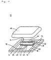
- Fig. 1 shows a piezoelectric component 10 which represents an embodiment of the present invention.
- the piezoelectric component 10 includes a supporting substrate 12 formed of an insulating material such as alumina.
- Two recesses 14 are formed in each of two opposite side portions of the supporting substrate 12.
- Two pattern electrodes 16 and 18 are formed on one of two major surfaces of the supporting substrate 12.
- the pattern electrode 16 has a first portion formed between one opposite pair of the recesses 14 and a second portion formed into the shape of L such as to extend along one of the above-mentioned opposite sides of the supporting substrate 12 and then toward a central portion of the supporting substrate 12.
- the pattern electrode 18 has a first portion formed between the other opposite pair of the recesses 14 and a second portion formed into the shape of L such as to extend along the other of the opposite sides of the supporting substrate 12 and then toward the central portion of the supporting substrate 12.
- the ends of the two pattern electrodes 16 and 18 at the center of the supporting substrate 12 are formed so as to be opposed to and spaced apart from each other.
- the first portions of the pattern electrodes 16 and 18 are formed so as to extend to positions on the other major surface of the supporting substrate 12 via the recesses 14.
- a piezoelectric resonator 20 is mounted on the ends of the pattern electrodes 16 and 18 at the center of the supporting substrate 12.
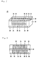
- the piezoelectric resonator 20 includes a base member 22 having, for example, the shape of a rectangular block, as shown in Fig. 2.
- the base member 22 is formed of, for example, a piezoelectric ceramic material.
- a plurality of internal electrodes 24 are formed in the base member 22, as shown in Fig. 3. Each internal electrode 24 is formed so that its major surfaces are perpendicular to the longitudinal direction of the base member 22.
- the base member 22 is polarized along its longitudinal direction so that a pair of its portions on the opposite sides of each internal electrode 24 are polarized in opposite directions, as indicated by the arrows in Fig. 3. However, the base member 22 is not polarized at the opposite ends in the longitudinal direction.
- a groove 25 is formed so as to extend in the longitudinal direction of the base member 22.
- the groove 25 is formed at the center in the widthwise direction of the base member 22 to bisect the side face of the base member 22.
- first insulating film 26 and second insulating film 28 are formed on the side face divided by the groove 25. Edges of the internal electrodes 24 exposed in one of the two portions of the side face of the base member 22 bisected by the groove 25 are alternately covered and left uncovered with the first insulating film 26. Edges of the internal electrodes 24 which are exposed in the other of the two portions of the side face of the base member 22 bisected by the groove 25 and which are opposite from those not covered with the first insulating film 26 are covered with the second insulating film 28.
- external electrodes 30 and 32 are formed on the portions of the base member 22 on which the first and second insulating films 26 and 28 are formed, i.e., on the opposite sides of the groove 25, so that the internal electrodes 24 not covered with the first insulating film 26 are connected to the external electrode 30 while the internal electrodes 24 not covered with the second insulating film 28 are connected to the external electrode 32. That is, in each adjacent pair of the internal electrodes 24, one is connected to the external electrode 30 or 32 while the other is connected to the external electrode 32 or 30.
- the external electrodes 30 and 32 are used as input/output electrodes.
- an electric field is applied to the portion between each adjacent pair of the internal electrodes 24 defining a section of the base member 22 other than opposite end sections.
- the base member 22 is thereby made piezoelectrically active in this section.
- the base member 22 is not made piezoelectrically active in the opposite end sections because the base member 22 is not polarized in the opposite end sections and because no electric field is applied to the opposite end sections since no electrodes are formed on the opposite end surfaces of the base member 22.
- the central section of the base member 22 is formed as an active section 36 which is activated by an input signal while the opposite end sections of the base member 22 are formed as inactive sections 38 which are not activated by an input signal.
- Each inactive section 38 is defined as a section in which no driving force is generated by an input signal. Accordingly, an electric field may be applied to the portion between each adjacent pair of the internal electrodes in the inactive sections 38, if the portion between the internal electrodes is not polarized. Also, a structure for inhibiting application of an electric field to some of the polarized piezoelectric layers may be used. It is not always necessary to form such inactive sections 38; the entire base member 22 may be formed as an active section.
- the thus-constructed piezoelectric resonator 20 is mounted on the pattern electrodes 16 and 18 on the supporting substrate 12. At this time, the piezoelectric resonator 20 are connected to the pattern electrodes 16 and 18 by two supporting members 40 formed of an electroconductive material. Portions of the external electrodes 30 and 32 of the piezoelectric resonator 20 defined at the center in the longitudinal direction are connected to the supporting members 40. Gaps between the piezoelectric resonator 20 and the supporting substrate 12 are filled with a rubber-like elastic material 42 such as silicone rubber or urethane. Further, rubber-like elastic material 44 is provided on the upper surface of the piezoelectric resonator 20. As these rubber-like elastic materials 42 and 44, a rubber-like elastic material having an insulating property, for example, is used.
- a metallic cap 46 is placed on the supporting substrate 12. To prevent the metal cap 46 from being short-circuited to the pattern electrodes 16 and 18, an insulating resin is applied to the supporting substrate 12 and the pattern electrodes 16 and 18 in advance. By capping with the metallic cap 46, the manufacture of the piezoelectric component 10 is completed. In this piezoelectric component 10, the pattern electrodes 16 and 18 formed so as to extend to the reverse surface of the supporting substrate 12 via the side surfaces of the supporting substrate 12 are used as input/output terminals for connection to an external circuit.
- the piezoelectric resonator 20 is of the stiffened type.
- the stiffened piezoelectric resonator 20 has a larger electromechanical coupling coefficient than unstiffened piezoelectric resonators in which the direction of vibration does not coincide with the direction of polarization and the direction of an electric field. Therefore, the stiffened piezoelectric resonator 20 has a larger difference ⁇ F between the resonant frequency and the antiresonant frequency. This means that the piezoelectric resonator 20 obtains wide-frequency-band characteristics.
- ⁇ F can be adjusted to a suitable value, for example, by changing the proportions of active section 36 and the inactive section 38 and/or by selecting the inactive section 38 formation position.
- the capacitance of the piezoelectric resonator 20 can be adjusted by changing the number of layers of the active section 36. Therefore, impedance matching between the piezoelectric component 10 and an external circuit can be achieved easily.
- any use of the piezoelectric component 10 e.g., use as a discriminator or an oscillator using one piezoelectric resonator 20 arranged as described above, a phase change at a frequency in the vicinity of the resonant frequency (Fr) and the antiresonant frequency (Fa) is utilized.
- the mechanical quality factor Qm of the piezoelectric resonator 20 is unnecessarily large, a ripple due to unnecessary vibration occurs in the operating range to seriously affect characteristics the piezoelectric resonator 20. Therefore, suppression of Qm is important. Because Qm of the piezoelectric resonator 20 itself is determined by the piezoelectric material of the base member 22, it cannot be controlled by selecting the size of the element, the number of piezoelectric layers and so on.
- Qm is controlled by the rubber-like elastic material 42 filling the gaps between the piezoelectric resonator 20 and the supporting substrate 12 and the rubber-like elastic material 44 applied on the upper surface of the piezoelectric resonator 20. That is, the vibration load on the piezoelectric resonator 20 is increased by these rubber-like elastic materials 42 and 44, thereby suppressing Qm of the piezoelectric resonator 20 substantially effectively.
- the desired value of Qm may be obtained by adjusting the amounts of the rubber-like elastic materials 42 and 44 while measuring characteristics of the piezoelectric component 10.
- both the rubber-like elastic materials 42 and 44 are not always necessary to use both the rubber-like elastic materials 42 and 44; only one of them may be used.
- Use of only the rubber-like elastic material 42 filling the gaps between the piezoelectric resonator 20 and the supporting substrate 12 is more effective in suppressing Qm than use of only the rubber-like elastic material applied on the upper surface of the piezoelectric resonator 20. This is because the rubber-like elastic material 42 adheres both to the piezoelectric resonator 20 and to the supporting substrate 12 to effectively suppress vibration of the piezoelectric resonator 20.
- the rubber-like elastic material 42 reinforces the support for the piezoelectric resonator 20.
- adjustment of Qm by applying the rubber-like elastic material 44 on the upper surface of the piezoelectric resonator 20 is more easier to perform if Qm is adjusted while characteristics of the piezoelectric component 10 are being measured.
- the vibration load on the piezoelectric resonator 20 becomes larger and the Qm suppression effect becomes higher.
- the piezoelectric resonator 20 vibrates, it has a larger displacement at its opposite ends since it vibrates in the longitudinal mode with a node corresponding to its center. Accordingly, a portion of the rubber-like elastic material 42 or 44 closer to each of the opposite ends of the piezoelectric resonator 20 contributes more largely to suppression of Qm.
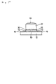
- an electroconductive rubber-like elastic material such as electroconductive silicone may be used as the rubber-like elastic material 42 between the piezoelectric resonator 20 and the supporting substrate 12. If such an electroconductive material is used as the rubber-like elastic material 42, the reliability of each of the electrical conduction between the external electrode 30 and the pattern electrode 16 and the electrical conduction between the external electrode 32 and the pattern electrode 18 can be improved. If such a material is used, an insulating rubber-like elastic material 50 is provided as a filler at the recess 25 such as to prevent electrical conduction between the two external electrodes 30 and 32, as shown in Fig. 5.
- Fig. 6 is a plan view of an essential portion of a piezoelectric component 10 which represents another embodiment of the present invention, and which is arranged as a ladder filter by using a plurality of piezoelectric resonators.
- Fig. 7 is a perspective view of the essential portion of this piezoelectric component 10.
- four pattern electrodes 90, 92, 94, and 96 are formed on a supporting substrate 12.
- the pattern electrodes 90 to 96 have first to fifth lands arranged in a row in the direction from one end toward the other end of the supporting substrate 12 while being spaced apart from each other.
- the first land is formed as a portion of the pattern electrode 90
- the second and fifth lands are formed as portions of the pattern electrode 92
- the third land is formed as a portion of the pattern electrode 94
- the fourth land is formed as a portion of the pattern electrode 96.
- External electrodes 30 and 32 of piezoelectric resonators 20a, 20b, 20c, and 20d are connected to these lands by supporting members 40.
- the piezoelectric resonators 20a, 20b, 20c, and 20d are mounted so as to form a ladder type circuit shown in Fig. 8.
- a metallic cap (not shown) is placed on the supporting substrate 12.
- This piezoelectric component 10 is used as a ladder filter having a ladder type circuit such as shown in Fig. 8.
- a ladder filter having a ladder type circuit such as shown in Fig. 8.
- two piezoelectric resonators 20a and 20c are used as series resonators while the other two piezoelectric resonators 20b and 20d are used as parallel resonators.
- Such a ladder filter is designed so that the parallel resonators 20b and 20d have much larger capacitances than the series resonators 20a and 20c.
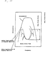
- an attenuation characteristic is determined by an impedance characteristic of the series resonators 20a and 20c and an impedance characteristic of the parallel resonators 20b and 20d, as shown in Fig. 9.
- a group delay characteristic (group delay time (GDT)) can be controlled by controlling Qm of the piezoelectric resonators 20a to 20d through the rubber-like elastic members 42 and 44.
- GDT group delay time
- Characteristics of a ladder filter formed in the above-described manner were examined.
- Fig. 10 shows the characteristics when Qm of each of the series and parallel piezoelectric resonators 20a to 20d was suppressed.
- Fig. 11 shows the characteristics when Qm of each of the series piezoelectric resonators 20a and 20c was suppressed.
- Fig. 12 shows the characteristics when Qm of each of the parallel piezoelectric resonators 20b and 20d was suppressed.
- the broken line indicates the group delay time before the application of the elastic materials while the solid line indicates the group delay time after the application of the elastic materials.
- GDT deviations can be improved by suppressing Qm of the piezoelectric resonators 20a to 20d, and the effect of improving GDT deviations is particularly high if the factors Qm of all the piezoelectric resonators 20a to 20d are suppressed.
- a change in amplitude characteristic of each resonator due to a change in Qm will not be discussed since it is very small.
- the mechanical quality factor Qm can be controlled substantially effectively without changing the piezoelectric material.
- a stiffened type laminated piezoelectric resonator is used as piezoelectric resonator 20 in the above-described piezoelectric components 10.
- an unstiffened piezoelectric resonator in which the direction of vibration does not coincide with the direction of polarization and the direction of an electric field may alternatively be used.
- Qm of the piezoelectric resonator can be controlled by the method of increasing the vibration load by using rubber-like elastic members 42 and 44.
- Qm of the piezoelectric resonator can be controlled by filling the gaps between the piezoelectric resonator and the supporting substrate with a rubber-like elastic material and/or by applying a rubber-like elastic material on the upper surface of the piezoelectric resonator.
Description
- The present invention relates generally to piezoelectric components and, more particularly, to a piezoelectric component comprising at least one piezoelectric resonator, such as an oscillator, a discriminator or a filter.
- Fig. 13 is a perspective view of a conventional
piezoelectric component 1. Thepiezoelectric component 1 includes a supportingsubstrate 2 on whichpattern electrodes piezoelectric resonator 4 is supported on this supportingsubstrate 2. Thepiezoelectric resonator 4 includes, for example, a vibratingbody 5 formed of a piezoelectric material andexternal electrodes body 5. When a signal is input between theexternal electrodes body 5. A supportingmember 7 is formed of, for example, an electroconductive material on thepattern electrode 3a. A central portion of thepiezoelectric resonator 4 is supported by the supportingmember 7. Simultaneously, theexternal electrode 6a of thepiezoelectric resonator 4 and thepattern electrode 3a are electrically connected to each other by the supportingmember 7. The otherexternal electrode 6b of thepiezoelectric resonator 4 is connected to thepattern electrode 3b by a lead wire 8. - In the thus-constructed
piezoelectric component 1, to obtain desired electrical characteristics, the resonant frequency, the degree of polarization and the capacitance between the terminals of thepiezoelectric resonator 4, etc., are designed according to the size design of thepiezoelectric resonator 4 and working conditions. - However, the piezoelectric resonator has a specific mechanical quality factor Qm according to the piezoelectric material used. To set Qm to the desired value, therefore, it has been necessary to develop an optimal piezoelectric material for setting the desired value or a piezoelectric material capable of setting a value close to the desired value. A long period of time is usually taken to develop a piezoelectric material. If a piezoelectric material capable of setting a value not equal to but close to the desired value is used, it is necessary to tolerate a range not corresponding to the target characteristic.
- US-A-5 406 682 discloses a method of compliantly mounting a piezoelectric device with a substrate. In this method, outer portions of a piezoelectric element are selectively metallized. Next, one layer of aluminum is selectively dispensed on the piezoelectric element. After this, an uncured conductive compliant material is placed and aligned on a substrate. Next, the piezoelectric element is placed and aligned on the conductive compliant material, such that upon curing the conductive compliant material forms a compliant mount connecting the outer metallized portions of the piezoelectric element with the substrate.
- EP-A-0 626 212 discloses a holding structure for a piezoelectric element. In this publication reference is made to Japanese Utility Model laid open Publication 20422/1993 which proposes a holding structure of piezoelectric vibrator wherein protrusions made of electrically conductive rectangular rubber are formed around a node point of vibrations of a piezoelectric vibrator and the piezoelectric vibrator is held at the protrusions.
- In view of the above-described problem, a main object of the present invention is to provide a piezoelectric component having a desired Qm by using a presently available piezoelectric material.
- To achieve this object, according to the present invention, there is provided a piezoelectric component of above mentioned kind, which is characterized in that a rubber-like elastic material is provided as a filler between said piezoelectric resonator and a substracte supporting it.
- In the above described piezoelectric component, the piezoelectric resonator may excite vibration in a longitudinal vibration mode.
- In the above described piezoelectric component, the piezoelectric resonator may further comprise a supporting substrate for supporting the piezoelectric resonator, and the rubber-like elastic material is provided as a filler between said piezoelectric resonator and said supporting substrate.
- In the above described piezoelectric component, the rubber-like elastic material may also be provided on a surface of said piezoelectric resonator opposite from another surface of said piezoelectric resonator facing said supporting substrate.
- In the above described piezoelectric component, the rubber-like elastic material may comprise an electroconductive material.
- In the above described piezoelectric component, the plurality of piezoelectric resonators may be connected on the supporting substrate in ladder shape for forming a ladder filter.
- In the above described piezoelectric component, the piezoelectric resonator may be a piezoelectric resonator which comprises a base member having a longitudinal direction, an active section composed of polarized piezoelectric member and constituting at least a part of the base member, and a pair of external electrodes provided with the active section, whereby at least one pair of internal electrodes are disposed in the active section such that the internal electrodes are perpendicular to the longitudinal direction of the base member and are connected to the pair of external electrodes respectively, the active section is polarized in the longitudinal direction of the base member, and a longitudinal mode basic vibration is excited when an electric field is applied to the longitudinal direction of the base member via the internal electrodes.
- In the above described piezoelectric resonator, an inactive section, in which vibration is not excited when the electric field is applied, may constitute the other part of the base member.
- The vibration load on the piezoelectric resonator is increased by providing a rubber-like elastic material provided on the piezoelectric resonator, for example being between the piezoelectric resonator and the supporting substrate or on the surface of the piezoelectric resonator remote from the supporting substrate or both between the piezoelectric resonator and the supporting substrate and on the surface of the piezoelectric resonator remote from the supporting substrate. If an electroconductive material is used as the rubber-like elastic material provided between the piezoelectric resonator and the supporting substrate, the reliability of electrical connection between electrodes on the supporting substrate and the piezoelectric resonator can be improved.
- In the ladder filter formed by connecting a plurality of the piezoelectric resonators in a ladder form, the vibration load on each piezoelectric resonator constituting the ladder filter can be adjusted by providing a rubber-like elastic material on the piezoelectric resonator.
- According to the present invention, the mechanical quality factor Qm of the piezoelectric resonator can be changed substantially effectively by increasing the vibration load on the piezoelectric resonator by the rubber-like elastic material. Accordingly, a piezoelectric component having the desired Qm can be obtained by adjusting the amount of the rubber-like elastic material. The reliability of electrical connection between electrodes on the supporting substrate and the piezoelectric resonator can be improved by using an electroconductive material as the rubber-like elastic material between the piezoelectric resonator and the supporting substrate. Thus, improved characteristics of the piezoelectric component can be obtained. A ladder filter having a plurality of piezoelectric resonators and having improved characteristics can also be obtained by performing such Qm adjustment with respect to each piezoelectric resonator.
- The above-described and other objects, features and advantages of the present invention will become apparent from the following detailed description of preferred embodiments of the invention with reference to the accompanying drawings.
-
- Fig. 1 is an exploded perspective view of a piezoelectric resonator which represents an embodiment of the present invention;
- Fig. 2 is a perspective view of a piezoelectric resonator used in the piezoelectric component shown in Fig. 1;
- Fig. 3 is a diagram showing the structure of the piezoelectric resonator shown in Fig. 2;
- Fig. 4 is a plan view of a state in which insulating films are formed on a base member used in the piezoelectric resonator shown in Fig. 2;
- Fig. 5 is a diagram of the structure using an electroconductive rubber-like elastic material between the piezoelectric resonator and the supporting substrate;
- Fig. 6 is a plan view of an essential portion of a piezoelectric component using a plurality of piezoelectric resonators to form a ladder filter in accordance with the present invention;
- Fig. 7 is an exploded perspective view of the essential portion of the ladder filter shown in Fig. 6;
- Fig. 8 is an equivalent circuit diagram of the ladder filter shown in Fig. 6;
- Fig. 9 is a graph showing the relationship between an attenuation characteristic and impedance characteristics of series and parallel resonators used in the ladder filter;
- Fig. 10 is a graph showing characteristics of the ladder filter with respect to adjustment of Qm of both the series and parallel resonators;
- Fig. 11 is a graph showing characteristics of the ladder filter with respect to adjustment of Qm of the series resonators;
- Fig. 12 is a graph showing characteristics of the ladder filter with respect to adjustment of Qm of the parallel resonators; and
- Fig. 13 is an exploded perspective view of a conventional piezoelectric component.
-
- Fig. 1 shows a
piezoelectric component 10 which represents an embodiment of the present invention. Thepiezoelectric component 10 includes a supportingsubstrate 12 formed of an insulating material such as alumina. Tworecesses 14 are formed in each of two opposite side portions of the supportingsubstrate 12. Twopattern electrodes substrate 12. Thepattern electrode 16 has a first portion formed between one opposite pair of therecesses 14 and a second portion formed into the shape of L such as to extend along one of the above-mentioned opposite sides of the supportingsubstrate 12 and then toward a central portion of the supportingsubstrate 12. Thepattern electrode 18 has a first portion formed between the other opposite pair of therecesses 14 and a second portion formed into the shape of L such as to extend along the other of the opposite sides of the supportingsubstrate 12 and then toward the central portion of the supportingsubstrate 12. The ends of the twopattern electrodes substrate 12 are formed so as to be opposed to and spaced apart from each other. The first portions of thepattern electrodes substrate 12 via therecesses 14. - A
piezoelectric resonator 20 is mounted on the ends of thepattern electrodes substrate 12. Thepiezoelectric resonator 20 includes abase member 22 having, for example, the shape of a rectangular block, as shown in Fig. 2. Thebase member 22 is formed of, for example, a piezoelectric ceramic material. A plurality ofinternal electrodes 24 are formed in thebase member 22, as shown in Fig. 3. Eachinternal electrode 24 is formed so that its major surfaces are perpendicular to the longitudinal direction of thebase member 22. Thebase member 22 is polarized along its longitudinal direction so that a pair of its portions on the opposite sides of eachinternal electrode 24 are polarized in opposite directions, as indicated by the arrows in Fig. 3. However, thebase member 22 is not polarized at the opposite ends in the longitudinal direction. - In one side face of the
base member 22, agroove 25 is formed so as to extend in the longitudinal direction of thebase member 22. Thegroove 25 is formed at the center in the widthwise direction of thebase member 22 to bisect the side face of thebase member 22. As shown in Fig. 4, on the side face divided by thegroove 25, first insulatingfilm 26 and second insulatingfilm 28 are formed. Edges of theinternal electrodes 24 exposed in one of the two portions of the side face of thebase member 22 bisected by thegroove 25 are alternately covered and left uncovered with the first insulatingfilm 26. Edges of theinternal electrodes 24 which are exposed in the other of the two portions of the side face of thebase member 22 bisected by thegroove 25 and which are opposite from those not covered with the first insulatingfilm 26 are covered with the second insulatingfilm 28. - Further,
external electrodes base member 22 on which the first and second insulatingfilms groove 25, so that theinternal electrodes 24 not covered with the first insulatingfilm 26 are connected to theexternal electrode 30 while theinternal electrodes 24 not covered with the second insulatingfilm 28 are connected to theexternal electrode 32. That is, in each adjacent pair of theinternal electrodes 24, one is connected to theexternal electrode external electrode - In this
piezoelectric resonator 20, theexternal electrodes piezoelectric resonator 20 is operated, an electric field is applied to the portion between each adjacent pair of theinternal electrodes 24 defining a section of thebase member 22 other than opposite end sections. Thebase member 22 is thereby made piezoelectrically active in this section. However, thebase member 22 is not made piezoelectrically active in the opposite end sections because thebase member 22 is not polarized in the opposite end sections and because no electric field is applied to the opposite end sections since no electrodes are formed on the opposite end surfaces of thebase member 22. Thus, the central section of thebase member 22 is formed as anactive section 36 which is activated by an input signal while the opposite end sections of thebase member 22 are formed asinactive sections 38 which are not activated by an input signal. Eachinactive section 38 is defined as a section in which no driving force is generated by an input signal. Accordingly, an electric field may be applied to the portion between each adjacent pair of the internal electrodes in theinactive sections 38, if the portion between the internal electrodes is not polarized. Also, a structure for inhibiting application of an electric field to some of the polarized piezoelectric layers may be used. It is not always necessary to form suchinactive sections 38; theentire base member 22 may be formed as an active section. - The thus-constructed
piezoelectric resonator 20 is mounted on thepattern electrodes substrate 12. At this time, thepiezoelectric resonator 20 are connected to thepattern electrodes members 40 formed of an electroconductive material. Portions of theexternal electrodes piezoelectric resonator 20 defined at the center in the longitudinal direction are connected to the supportingmembers 40. Gaps between thepiezoelectric resonator 20 and the supportingsubstrate 12 are filled with a rubber-likeelastic material 42 such as silicone rubber or urethane. Further, rubber-likeelastic material 44 is provided on the upper surface of thepiezoelectric resonator 20. As these rubber-likeelastic materials - A
metallic cap 46 is placed on the supportingsubstrate 12. To prevent themetal cap 46 from being short-circuited to thepattern electrodes substrate 12 and thepattern electrodes metallic cap 46, the manufacture of thepiezoelectric component 10 is completed. In thispiezoelectric component 10, thepattern electrodes substrate 12 via the side surfaces of the supportingsubstrate 12 are used as input/output terminals for connection to an external circuit. - When a signal is input to this
piezoelectric component 10 through thepattern electrodes active section 36 polarized in opposite directions, so that the piezoelectric layers expand and contract in the same direction as a whole. Vibration is thereby excited in the longitudinal fundamental mode with a node corresponding to the center of thebase member 22. - In this
piezoelectric component 10, the direction of polarization of theactive section 36, the direction of each electric field according to a signal and the direction of vibration of theactive section 36 coincide with each other. That is, thepiezoelectric resonator 20 is of the stiffened type. The stiffenedpiezoelectric resonator 20 has a larger electromechanical coupling coefficient than unstiffened piezoelectric resonators in which the direction of vibration does not coincide with the direction of polarization and the direction of an electric field. Therefore, the stiffenedpiezoelectric resonator 20 has a larger difference ΔF between the resonant frequency and the antiresonant frequency. This means that thepiezoelectric resonator 20 obtains wide-frequency-band characteristics. - In the
piezoelectric resonator 20, ΔF can be adjusted to a suitable value, for example, by changing the proportions ofactive section 36 and theinactive section 38 and/or by selecting theinactive section 38 formation position. The capacitance of thepiezoelectric resonator 20 can be adjusted by changing the number of layers of theactive section 36. Therefore, impedance matching between thepiezoelectric component 10 and an external circuit can be achieved easily. - In any use of the
piezoelectric component 10, e.g., use as a discriminator or an oscillator using onepiezoelectric resonator 20 arranged as described above, a phase change at a frequency in the vicinity of the resonant frequency (Fr) and the antiresonant frequency (Fa) is utilized. However, if the mechanical quality factor Qm of thepiezoelectric resonator 20 is unnecessarily large, a ripple due to unnecessary vibration occurs in the operating range to seriously affect characteristics thepiezoelectric resonator 20. Therefore, suppression of Qm is important. Because Qm of thepiezoelectric resonator 20 itself is determined by the piezoelectric material of thebase member 22, it cannot be controlled by selecting the size of the element, the number of piezoelectric layers and so on. - In this
piezoelectric component 10, therefore, Qm is controlled by the rubber-likeelastic material 42 filling the gaps between thepiezoelectric resonator 20 and the supportingsubstrate 12 and the rubber-likeelastic material 44 applied on the upper surface of thepiezoelectric resonator 20. That is, the vibration load on thepiezoelectric resonator 20 is increased by these rubber-likeelastic materials piezoelectric resonator 20 substantially effectively. The desired value of Qm may be obtained by adjusting the amounts of the rubber-likeelastic materials piezoelectric component 10. - It is not always necessary to use both the rubber-like
elastic materials elastic material 42 filling the gaps between thepiezoelectric resonator 20 and the supportingsubstrate 12 is more effective in suppressing Qm than use of only the rubber-like elastic material applied on the upper surface of thepiezoelectric resonator 20. This is because the rubber-likeelastic material 42 adheres both to thepiezoelectric resonator 20 and to the supportingsubstrate 12 to effectively suppress vibration of thepiezoelectric resonator 20. The rubber-likeelastic material 42 reinforces the support for thepiezoelectric resonator 20. However, adjustment of Qm by applying the rubber-likeelastic material 44 on the upper surface of thepiezoelectric resonator 20 is more easier to perform if Qm is adjusted while characteristics of thepiezoelectric component 10 are being measured. - If the amounts of the rubber-like
elastic materials piezoelectric resonator 20 becomes larger and the Qm suppression effect becomes higher. When thepiezoelectric resonator 20 vibrates, it has a larger displacement at its opposite ends since it vibrates in the longitudinal mode with a node corresponding to its center. Accordingly, a portion of the rubber-likeelastic material piezoelectric resonator 20 contributes more largely to suppression of Qm. - As the rubber-like
elastic material 42 between thepiezoelectric resonator 20 and the supportingsubstrate 12, an electroconductive rubber-like elastic material such as electroconductive silicone may be used. If such an electroconductive material is used as the rubber-likeelastic material 42, the reliability of each of the electrical conduction between theexternal electrode 30 and thepattern electrode 16 and the electrical conduction between theexternal electrode 32 and thepattern electrode 18 can be improved. If such a material is used, an insulating rubber-likeelastic material 50 is provided as a filler at therecess 25 such as to prevent electrical conduction between the twoexternal electrodes - Fig. 6 is a plan view of an essential portion of a
piezoelectric component 10 which represents another embodiment of the present invention, and which is arranged as a ladder filter by using a plurality of piezoelectric resonators. Fig. 7 is a perspective view of the essential portion of thispiezoelectric component 10. In thispiezoelectric component 10, fourpattern electrodes substrate 12. Thepattern electrodes 90 to 96 have first to fifth lands arranged in a row in the direction from one end toward the other end of the supportingsubstrate 12 while being spaced apart from each other. The first land is formed as a portion of thepattern electrode 90, the second and fifth lands are formed as portions of thepattern electrode 92, the third land is formed as a portion of thepattern electrode 94, and the fourth land is formed as a portion of thepattern electrode 96. -
External electrodes piezoelectric resonators members 40. Thepiezoelectric resonators substrate 12. - This
piezoelectric component 10 is used as a ladder filter having a ladder type circuit such as shown in Fig. 8. To form such a ladder filter, twopiezoelectric resonators piezoelectric resonators parallel resonators series resonators series resonators parallel resonators - In such a ladder filter, a group delay characteristic (group delay time (GDT)) can be controlled by controlling Qm of the
piezoelectric resonators 20a to 20d through the rubber-likeelastic members piezoelectric resonators 20a to 20d was suppressed. Fig. 11 shows the characteristics when Qm of each of theseries piezoelectric resonators piezoelectric resonators - As can be understood from Figs. 10, 11, and 12, GDT deviations can be improved by suppressing Qm of the
piezoelectric resonators 20a to 20d, and the effect of improving GDT deviations is particularly high if the factors Qm of all thepiezoelectric resonators 20a to 20d are suppressed. A change in amplitude characteristic of each resonator due to a change in Qm will not be discussed since it is very small. - As described above, if rubber-like
elastic materials piezoelectric resonator 20 in the above-describedpiezoelectric components 10. However, an unstiffened piezoelectric resonator in which the direction of vibration does not coincide with the direction of polarization and the direction of an electric field may alternatively be used. Also in a case where such an unstiffened piezoelectric resonator capable of longitudinal vibration is used, Qm of the piezoelectric resonator can be controlled by the method of increasing the vibration load by using rubber-likeelastic members - Also in a piezoelectric component using a piezoelectric resonator having external electrodes formed on opposite surfaces of a base member and also using a lead wire as shown in Fig. 13, Qm of the piezoelectric resonator can be controlled by filling the gaps between the piezoelectric resonator and the supporting substrate with a rubber-like elastic material and/or by applying a rubber-like elastic material on the upper surface of the piezoelectric resonator.
Claims (7)
- A piezoelectric component (10) comprising at least one piezoelectric resonator (20) and a rubber-like elastic material (42, 44) provided on said piezoelectric resonator (20),
characterized in that
said piezoelectric component (10) further comprises a supporting substrate (12) for supporting said piezoelectric resonator (20) and
said rubber-like elastic material (42) is provided as a filler between said piezoelectric resonator (20) and said supporting substrate (12). - A piezoelectric component (10) according to Claim 1, characterized in that said piezoelectric resonator (20) exciter vibration in a longitudinal vibration mode.
- A piezoelectric component according to claim 1 or 2, characterized in that said rubber-like elastic material (44) is provided on a surface of said piezoelectric resonator (20) opposite from another surface of said piezoelectric resonator (20) facing said supporting substrate (12).
- A piezoelectric component (10) according to one of Claims 1 to 3, characterized in that said rubber-like elastic material (42,44) comprises an electroconductive material.
- A piezoelectric component (10) according to one of Claims 1 to 4, characterized in that a plurality of said piezoelectric resonators (20a,20b,20c,20d) are connected on said supporting substrate (12) in ladder shape for forming a ladder filter.
- A piezoelectric component according to one of Claims 1 to 5, characterized in that said piezoelectric resonator (10) comprises a base member (22) having a longitudinal direction, an active section (36) composed of polarized piezoelectric member and constituting at least a part of said base member (22), and a pair of external electrodes (30,32) provided with said active section (36), whereby at least one pair of internal electrodes (24) are disposed in said active section (36) such that the internal electrodes (14) are perpendicular to the longitudinal direction of said base member (22) and are connected to said pair of external electrodes (30,32) respectively, said active section (36) is polarized in the longitudinal direction of said base member (22), and a longitudinal mode basic vibration is excited when an electric field is applied to the longitudinal direction of said base member (22) via said internal electrodes (14).
- A piezoelectric component according to Claim 6, characterized in that an inactive section (38), in which vibration is not excited when said electric field is applied, constitutes the other part of said base member (22).
Applications Claiming Priority (15)
| Application Number | Priority Date | Filing Date | Title |
|---|---|---|---|
| JP11047596A JP3271517B2 (en) | 1996-04-05 | 1996-04-05 | Piezoelectric resonator and electronic component using the same |
| JP110475/96 | 1996-04-05 | ||
| JP11047596 | 1996-04-05 | ||
| JP12272596 | 1996-04-18 | ||
| JP12272596 | 1996-04-18 | ||
| JP122725/96 | 1996-04-18 | ||
| JP22302996 | 1996-08-05 | ||
| JP223029/96 | 1996-08-05 | ||
| JP22302996 | 1996-08-05 | ||
| JP2010397 | 1997-01-16 | ||
| JP20102/97 | 1997-01-16 | ||
| JP2010297 | 1997-01-16 | ||
| JP02010397A JP3378163B2 (en) | 1996-08-05 | 1997-01-16 | Piezo components |
| JP02010297A JP3266031B2 (en) | 1996-04-18 | 1997-01-16 | Piezoelectric resonator and electronic component using the same |
| JP20103/97 | 1997-01-16 |
Publications (3)
| Publication Number | Publication Date |
|---|---|
| EP0809356A2 EP0809356A2 (en) | 1997-11-26 |
| EP0809356A3 EP0809356A3 (en) | 1998-08-12 |
| EP0809356B1 true EP0809356B1 (en) | 2003-09-17 |
Family
ID=27520195
Family Applications (1)
| Application Number | Title | Priority Date | Filing Date |
|---|---|---|---|
| EP97105634A Expired - Lifetime EP0809356B1 (en) | 1996-04-05 | 1997-04-04 | Piezoelectric component |
Country Status (3)
| Country | Link |
|---|---|
| US (1) | US6016024A (en) |
| EP (1) | EP0809356B1 (en) |
| DE (1) | DE69724869T2 (en) |
Families Citing this family (9)
| Publication number | Priority date | Publication date | Assignee | Title |
|---|---|---|---|---|
| US5939819A (en) * | 1996-04-18 | 1999-08-17 | Murata Manufacturing Co., Ltd. | Electronic component and ladder filter |
| US6114800A (en) * | 1997-10-01 | 2000-09-05 | Murata Manufacturing Co., Ltd | Piezoelectric component |
| JP3262050B2 (en) * | 1997-10-03 | 2002-03-04 | 株式会社村田製作所 | Electronic components and ladder filters |
| JPH11112279A (en) * | 1997-10-03 | 1999-04-23 | Murata Mfg Co Ltd | Piezoelectric component |
| US6229249B1 (en) * | 1998-08-31 | 2001-05-08 | Kyocera Corporation | Surface-mount type crystal oscillator |
| JP3677673B2 (en) * | 1999-03-30 | 2005-08-03 | 株式会社村田製作所 | Piezoelectric resonator holding structure and piezoelectric component having the same |
| JP2001016059A (en) * | 1999-04-26 | 2001-01-19 | Murata Mfg Co Ltd | Method for adjusting group delay characteristic of piezoelectric resonator |
| US6653762B2 (en) * | 2000-04-19 | 2003-11-25 | Murata Manufacturing Co., Ltd. | Piezoelectric type electric acoustic converter |
| JP3538709B2 (en) * | 2000-06-14 | 2004-06-14 | 株式会社村田製作所 | Piezoelectric resonance components |
Family Cites Families (51)
| Publication number | Priority date | Publication date | Assignee | Title |
|---|---|---|---|---|
| US2157665A (en) * | 1935-10-16 | 1939-05-09 | Telefunken Gmbh | Crystal mounting with temperature compensation |
| US2636135A (en) * | 1947-10-29 | 1953-04-21 | Bell Telephone Labor Inc | Stress-coupled core and crystal transformer |
| US3185869A (en) * | 1961-12-01 | 1965-05-25 | Endevco Corp | Transducer |
| US3297889A (en) * | 1964-01-15 | 1967-01-10 | Breskend Sam | Clock driver |
| US3401275A (en) * | 1966-04-14 | 1968-09-10 | Clevite Corp | Composite resonator |
| GB1207974A (en) * | 1966-11-17 | 1970-10-07 | Clevite Corp | Frequency selective apparatus including a piezoelectric device |
| CH607336A5 (en) * | 1975-09-22 | 1978-12-15 | Siemens Ag | |
| US4193009A (en) * | 1976-01-26 | 1980-03-11 | Durley Benton A Iii | Ultrasonic piezoelectric transducer using a rubber mounting |
| GB2044527B (en) * | 1978-12-27 | 1983-05-25 | Murata Manufacturing Co | Piezoelectric unit and device |
| US4398117A (en) * | 1981-03-23 | 1983-08-09 | Sperry Corporation | Bellows support for surface acoustic wave device |
| JPS59117814A (en) * | 1982-12-24 | 1984-07-07 | Murata Mfg Co Ltd | Piezoelectric porcelain resonator |
| CA1214835A (en) * | 1982-12-28 | 1986-12-02 | Murata Manufacturing Co., Ltd. | Piezoelectric resonator |
| JPS601877A (en) * | 1983-06-20 | 1985-01-08 | Nippon Soken Inc | Laminated piezoelectric unit |
| US4564782A (en) * | 1983-09-02 | 1986-01-14 | Murata Manufacturing Co., Ltd. | Ceramic filter using multiple thin piezoelectric layers |
| JPS6086880A (en) * | 1983-10-19 | 1985-05-16 | Nec Corp | Electrostrictive-effect element |
| JPS60169927U (en) * | 1984-04-17 | 1985-11-11 | 株式会社村田製作所 | ladder type filter |
| JPS60174312U (en) * | 1984-04-27 | 1985-11-19 | 京セラ株式会社 | crystal oscillator |
| US4542315A (en) * | 1984-05-15 | 1985-09-17 | Murata Manufacturing Co., Ltd. | Chip-shaped piezoelectric vibrator mount |
| JPS61139112A (en) * | 1984-12-10 | 1986-06-26 | Murata Mfg Co Ltd | Layer-built piezoelectric element capable of frequency adjustment |
| US4752712A (en) * | 1985-06-10 | 1988-06-21 | Nippon Soken, Inc. | Piezoelectric laminate stack |
| US4885498A (en) * | 1985-06-19 | 1989-12-05 | Ngk Spark Plug Co., Ltd. | Stacked type piezoelectric actuator |
| JPH0732273B2 (en) * | 1986-05-22 | 1995-04-10 | 日本電気株式会社 | Electrostrictive effect element |
| JP2790177B2 (en) * | 1987-07-06 | 1998-08-27 | 株式会社村田製作所 | Electrostrictive resonance element |
| US5045744A (en) * | 1988-12-23 | 1991-09-03 | Murata Mfg. Co. | Energy-trapping-by-frequency-lowering-type piezoelectric-resonance device |
| US5118982A (en) * | 1989-05-31 | 1992-06-02 | Nec Corporation | Thickness mode vibration piezoelectric transformer |
| JP3041952B2 (en) * | 1990-02-23 | 2000-05-15 | セイコーエプソン株式会社 | Ink jet recording head, piezoelectric vibrator, and method of manufacturing these |
| JP2965602B2 (en) * | 1990-02-26 | 1999-10-18 | 日立金属株式会社 | Stacked displacement element |
| US5126618A (en) * | 1990-03-06 | 1992-06-30 | Brother Kogyo Kabushiki Kaisha | Longitudinal-effect type laminar piezoelectric/electrostrictive driver, and printing actuator using the driver |
| JPH04214686A (en) * | 1990-10-05 | 1992-08-05 | Nec Corp | Electrostrictive effect element |
| DE4201937C2 (en) * | 1991-01-25 | 1997-05-22 | Murata Manufacturing Co | Piezoelectric laminated actuator |
| JP3185226B2 (en) * | 1991-01-30 | 2001-07-09 | 株式会社村田製作所 | Driving method of piezoelectric bimorph element and piezoelectric bimorph element |
| JP3064458B2 (en) * | 1991-04-02 | 2000-07-12 | 日本電気株式会社 | Thickness longitudinal vibration piezoelectric transformer and its driving method |
| JPH04333295A (en) * | 1991-05-09 | 1992-11-20 | Nec Corp | Electrostrictive effect element and manufacture thereof |
| US5225731A (en) * | 1991-06-13 | 1993-07-06 | Southwest Research Institute | Solid body piezoelectric bender transducer |
| JPH05160459A (en) * | 1991-12-09 | 1993-06-25 | Hitachi Metals Ltd | Laminated displacement element |
| JPH05264391A (en) * | 1992-03-19 | 1993-10-12 | Unisia Jecs Corp | Pressure sensor |
| US5250870A (en) * | 1992-03-25 | 1993-10-05 | Motorola, Inc. | Ultra-thin surface mount crystal package |
| JPH06209228A (en) * | 1993-01-12 | 1994-07-26 | Murata Mfg Co Ltd | Ladder type filter |
| US5381067A (en) * | 1993-03-10 | 1995-01-10 | Hewlett-Packard Company | Electrical impedance normalization for an ultrasonic transducer array |
| KR100204457B1 (en) * | 1993-05-28 | 1999-06-15 | 모리시타 요이찌 | Piezoelectric oscillator and manufacturing method |
| US5648746A (en) * | 1993-08-17 | 1997-07-15 | Murata Manufacturing Co., Ltd. | Stacked diezoelectric resonator ladder-type filter with at least one width expansion mode resonator |
| JPH07106905A (en) * | 1993-10-06 | 1995-04-21 | Matsushita Electric Ind Co Ltd | Oscillator |
| US5406682A (en) * | 1993-12-23 | 1995-04-18 | Motorola, Inc. | Method of compliantly mounting a piezoelectric device |
| US5585687A (en) * | 1994-02-23 | 1996-12-17 | Citizen Watch Co., Ltd. | Piezolelectric oscillator |
| JPH07240660A (en) * | 1994-02-25 | 1995-09-12 | Murata Mfg Co Ltd | Ladder filter |
| JPH0818382A (en) * | 1994-06-27 | 1996-01-19 | Murata Mfg Co Ltd | Piezoelectric component |
| JP3221253B2 (en) * | 1994-09-13 | 2001-10-22 | 株式会社村田製作所 | Manufacturing method of composite electronic components |
| JP3114526B2 (en) * | 1994-10-17 | 2000-12-04 | 株式会社村田製作所 | Chip type piezoelectric resonance component |
| US5572082A (en) * | 1994-11-14 | 1996-11-05 | Sokol; Thomas J. | Monolithic crystal strip filter |
| JP3141723B2 (en) * | 1995-04-11 | 2001-03-05 | 株式会社村田製作所 | Resonator and resonance component using width mode |
| JP3218971B2 (en) * | 1996-04-01 | 2001-10-15 | 株式会社村田製作所 | Ladder type filter |
-
1997
- 1997-04-02 US US08/832,072 patent/US6016024A/en not_active Expired - Lifetime
- 1997-04-04 EP EP97105634A patent/EP0809356B1/en not_active Expired - Lifetime
- 1997-04-04 DE DE69724869T patent/DE69724869T2/en not_active Expired - Lifetime
Also Published As
| Publication number | Publication date |
|---|---|
| EP0809356A2 (en) | 1997-11-26 |
| DE69724869T2 (en) | 2004-05-06 |
| EP0809356A3 (en) | 1998-08-12 |
| US6016024A (en) | 2000-01-18 |
| DE69724869D1 (en) | 2003-10-23 |
Similar Documents
| Publication | Publication Date | Title |
|---|---|---|
| US5925970A (en) | Piezoelectric resonator and electronic component containing same | |
| US6472610B1 (en) | Support structure for electronic component | |
| EP0809356B1 (en) | Piezoelectric component | |
| US6111343A (en) | Piezoelectric resonator and electronic component including same | |
| US6091180A (en) | Piezoelectric resonator and electronic component using the same | |
| US5925971A (en) | Piezoelectric resonator and electronic component containing same | |
| US6028390A (en) | Piezoelectric resonator and electronic component including same | |
| EP0907240B1 (en) | Method of manufacturing piezoelectric resonator | |
| US6144141A (en) | Piezoelectric resonator and electronic component containing same | |
| US6064142A (en) | Piezoelectric resonator and electronic component containing same | |
| EP0874456B1 (en) | Piezoelectric resonator and electronic component using the same | |
| US6297581B1 (en) | Piezoelectric element and electronic component including same | |
| JP3378163B2 (en) | Piezo components | |
| KR100272179B1 (en) | Piezoelectric component | |
| JP3271538B2 (en) | Piezoelectric resonator and electronic component using the same | |
| US6376970B1 (en) | Piezoelectric resonator supporting structure and a piezoelectric component including the same | |
| EP0800268B1 (en) | Piezoelectric resonator | |
| CN1078771C (en) | Piezoelectric component | |
| JPH11112277A (en) | Electronic component and ladder filter | |
| KR100280071B1 (en) | Piezoelectric resonator and electric component including same | |
| JPH03165613A (en) | Piezoelectric component | |
| JPH11112278A (en) | Piezoelectric component | |
| JPH0241205B2 (en) | ||
| JPH06232675A (en) | Piezoelectric resonator component |
Legal Events
| Date | Code | Title | Description |
|---|---|---|---|
| PUAI | Public reference made under article 153(3) epc to a published international application that has entered the european phase |
Free format text: ORIGINAL CODE: 0009012 |
|
| AK | Designated contracting states |
Kind code of ref document: A2 Designated state(s): DE FI FR SE |
|
| DAC | Divisional application: reference to earlier application (deleted) | ||
| PUAL | Search report despatched |
Free format text: ORIGINAL CODE: 0009013 |
|
| AK | Designated contracting states |
Kind code of ref document: A3 Designated state(s): DE FI FR SE |
|
| 17P | Request for examination filed |
Effective date: 19981117 |
|
| 17Q | First examination report despatched |
Effective date: 20010912 |
|
| GRAH | Despatch of communication of intention to grant a patent |
Free format text: ORIGINAL CODE: EPIDOS IGRA |
|
| GRAH | Despatch of communication of intention to grant a patent |
Free format text: ORIGINAL CODE: EPIDOS IGRA |
|
| GRAA | (expected) grant |
Free format text: ORIGINAL CODE: 0009210 |
|
| AK | Designated contracting states |
Kind code of ref document: B1 Designated state(s): DE FI FR SE |
|
| PG25 | Lapsed in a contracting state [announced via postgrant information from national office to epo] |
Ref country code: FI Free format text: LAPSE BECAUSE OF FAILURE TO SUBMIT A TRANSLATION OF THE DESCRIPTION OR TO PAY THE FEE WITHIN THE PRESCRIBED TIME-LIMIT Effective date: 20030917 |
|
| REF | Corresponds to: |
Ref document number: 69724869 Country of ref document: DE Date of ref document: 20031023 Kind code of ref document: P |
|
| PG25 | Lapsed in a contracting state [announced via postgrant information from national office to epo] |
Ref country code: SE Free format text: LAPSE BECAUSE OF FAILURE TO SUBMIT A TRANSLATION OF THE DESCRIPTION OR TO PAY THE FEE WITHIN THE PRESCRIBED TIME-LIMIT Effective date: 20031217 |
|
| ET | Fr: translation filed | ||
| PLBE | No opposition filed within time limit |
Free format text: ORIGINAL CODE: 0009261 |
|
| STAA | Information on the status of an ep patent application or granted ep patent |
Free format text: STATUS: NO OPPOSITION FILED WITHIN TIME LIMIT |
|
| 26N | No opposition filed |
Effective date: 20040618 |
|
| REG | Reference to a national code |
Ref country code: FR Ref legal event code: PLFP Year of fee payment: 20 |
|
| PGFP | Annual fee paid to national office [announced via postgrant information from national office to epo] |
Ref country code: DE Payment date: 20160421 Year of fee payment: 20 |
|
| PGFP | Annual fee paid to national office [announced via postgrant information from national office to epo] |
Ref country code: FR Payment date: 20160421 Year of fee payment: 20 |
|
| REG | Reference to a national code |
Ref country code: DE Ref legal event code: R071 Ref document number: 69724869 Country of ref document: DE |