EP0809872B1 - Coaxial cable connector - Google Patents
Coaxial cable connector Download PDFInfo
- Publication number
- EP0809872B1 EP0809872B1 EP96936809A EP96936809A EP0809872B1 EP 0809872 B1 EP0809872 B1 EP 0809872B1 EP 96936809 A EP96936809 A EP 96936809A EP 96936809 A EP96936809 A EP 96936809A EP 0809872 B1 EP0809872 B1 EP 0809872B1
- Authority
- EP
- European Patent Office
- Prior art keywords
- entry body
- ferrule
- clamp nut
- pin terminal
- mandrel
- Prior art date
- Legal status (The legal status is an assumption and is not a legal conclusion. Google has not performed a legal analysis and makes no representation as to the accuracy of the status listed.)
- Expired - Lifetime
Links
- 239000012212 insulator Substances 0.000 claims abstract description 26
- 230000013011 mating Effects 0.000 claims abstract description 11
- 230000000007 visual effect Effects 0.000 claims abstract description 3
- 239000004020 conductor Substances 0.000 claims description 34
- 229910052751 metal Inorganic materials 0.000 claims description 9
- 239000002184 metal Substances 0.000 claims description 9
- 229910052782 aluminium Inorganic materials 0.000 claims description 8
- XAGFODPZIPBFFR-UHFFFAOYSA-N aluminium Chemical compound [Al] XAGFODPZIPBFFR-UHFFFAOYSA-N 0.000 claims description 8
- 239000004411 aluminium Substances 0.000 claims description 4
- 229910001369 Brass Inorganic materials 0.000 claims description 3
- 239000010951 brass Substances 0.000 claims description 3
- 239000012777 electrically insulating material Substances 0.000 claims 2
- 229910000881 Cu alloy Inorganic materials 0.000 claims 1
- 238000000034 method Methods 0.000 description 5
- 230000015556 catabolic process Effects 0.000 description 3
- 238000006731 degradation reaction Methods 0.000 description 3
- 238000009434 installation Methods 0.000 description 3
- 238000007789 sealing Methods 0.000 description 3
- 239000000356 contaminant Substances 0.000 description 2
- 239000012811 non-conductive material Substances 0.000 description 2
- 230000003313 weakening effect Effects 0.000 description 2
- RYGMFSIKBFXOCR-UHFFFAOYSA-N Copper Chemical compound [Cu] RYGMFSIKBFXOCR-UHFFFAOYSA-N 0.000 description 1
- CBENFWSGALASAD-UHFFFAOYSA-N Ozone Chemical compound [O-][O+]=O CBENFWSGALASAD-UHFFFAOYSA-N 0.000 description 1
- 230000006835 compression Effects 0.000 description 1
- 238000007906 compression Methods 0.000 description 1
- 239000010949 copper Substances 0.000 description 1
- 229910052802 copper Inorganic materials 0.000 description 1
- 230000007797 corrosion Effects 0.000 description 1
- 238000005260 corrosion Methods 0.000 description 1
- 230000001419 dependent effect Effects 0.000 description 1
- 239000000463 material Substances 0.000 description 1
- 230000000630 rising effect Effects 0.000 description 1
Images

Classifications
-
- H—ELECTRICITY
- H01—ELECTRIC ELEMENTS
- H01R—ELECTRICALLY-CONDUCTIVE CONNECTIONS; STRUCTURAL ASSOCIATIONS OF A PLURALITY OF MUTUALLY-INSULATED ELECTRICAL CONNECTING ELEMENTS; COUPLING DEVICES; CURRENT COLLECTORS
- H01R9/00—Structural associations of a plurality of mutually-insulated electrical connecting elements, e.g. terminal strips or terminal blocks; Terminals or binding posts mounted upon a base or in a case; Bases therefor
- H01R9/03—Connectors arranged to contact a plurality of the conductors of a multiconductor cable, e.g. tapping connections
- H01R9/05—Connectors arranged to contact a plurality of the conductors of a multiconductor cable, e.g. tapping connections for coaxial cables
- H01R9/0521—Connection to outer conductor by action of a nut
-
- H—ELECTRICITY
- H01—ELECTRIC ELEMENTS
- H01R—ELECTRICALLY-CONDUCTIVE CONNECTIONS; STRUCTURAL ASSOCIATIONS OF A PLURALITY OF MUTUALLY-INSULATED ELECTRICAL CONNECTING ELEMENTS; COUPLING DEVICES; CURRENT COLLECTORS
- H01R13/00—Details of coupling devices of the kinds covered by groups H01R12/70 or H01R24/00 - H01R33/00
- H01R13/64—Means for preventing incorrect coupling
- H01R13/641—Means for preventing incorrect coupling by indicating incorrect coupling; by indicating correct or full engagement
-
- H—ELECTRICITY
- H01—ELECTRIC ELEMENTS
- H01R—ELECTRICALLY-CONDUCTIVE CONNECTIONS; STRUCTURAL ASSOCIATIONS OF A PLURALITY OF MUTUALLY-INSULATED ELECTRICAL CONNECTING ELEMENTS; COUPLING DEVICES; CURRENT COLLECTORS
- H01R2103/00—Two poles
-
- H—ELECTRICITY
- H01—ELECTRIC ELEMENTS
- H01R—ELECTRICALLY-CONDUCTIVE CONNECTIONS; STRUCTURAL ASSOCIATIONS OF A PLURALITY OF MUTUALLY-INSULATED ELECTRICAL CONNECTING ELEMENTS; COUPLING DEVICES; CURRENT COLLECTORS
- H01R24/00—Two-part coupling devices, or either of their cooperating parts, characterised by their overall structure
- H01R24/38—Two-part coupling devices, or either of their cooperating parts, characterised by their overall structure having concentrically or coaxially arranged contacts
- H01R24/40—Two-part coupling devices, or either of their cooperating parts, characterised by their overall structure having concentrically or coaxially arranged contacts specially adapted for high frequency
Definitions
- the invention relates generally to electrical connectors, and more particularly to coaxial cable connectors used in conjunction with either semi-rigid coaxial cable or flexible coaxial cable.
- Coaxial cables typically consist of a central conductor which is surrounded by a metallic outer conductor.
- An insulator separates the central conductor from the outer conductor, and an insulating jacket covers the outer conductor.
- the outer conductor is usually in one of two forms, either a copper braid or an aluminum sheath.
- Coaxial cables of this type are used broadly, especially in cable television applications.
- the coaxial cable provides for high quality transportation of signals.
- a connector In order to effectively use the cables, a connector must be fitted to at least one end of the cable.
- a connector in order to be practical, must provide for a reliable mechanical and electrical connection as well as being simple to install and use. It is further desirable that the connector positively release the center conductor upon disassembly and that the connector hold the cable stationary during twisting of the clamp nut.
- United States patent No. 4,952,174 discloses a coaxial cable connector for use with a prepared end of a coaxial cable.
- the connector comprises a body and a nut threadably tightenable to the body.
- the nut defines an interior space including a mandrel assembly which is freely rotatable within the interior space until the nut is tightened to the body.
- the mandrel assembly includes an insulator cone for guiding the centre conductor and a clamping arrangement for engaging and clamping a centre pin chuck as the nut is tightened to the body.
- a mandrel is slidably mounted under the cable outer metal jacket in a space provided after removal of a portion of the dielectric core incident to preparation of the cable end.
- a ferrule is slidably mounted over the outer jacket and the ferrule includes collet fingers disposed over a portion of the mandrel.
- the mandrel closes the collet fingers to cause them to compress the outer metal jacket against a portion of the connector during the installation of the connector to the prepared cable end.
- the connector of US 4,952,174 uses a ferrule that moves relative to a mandrel shell to close the ferrule about the cable.
- the ferrule incorporates a plurality of times that are used to grip the conductive sheath.
- This implementation has the disadvantage that the tines may deform, pleat or weaken the conductive sheath and in addition do not grip the outermost insulator of the coaxial jacket.
- the mandrel is composed of a metal sleeve, which allows a frequency response that is inherent with a metal mandrel, and can establish a parallel electrical contact with the contact established by the ferrule between the cable's conductive sheath and the connector body. Therefore, it would be desirable to reduce deformation of the conductive sheath, limit frequency resonance and assure only one conductive path between the conductive sheath and the connector body.
- the present invention provides a two piece coaxial cable connector comprising: a clamp nut open on each of two ends, said clamp nut defining an interior space, a first end of said clamp nut for receiving a coaxial cable, a portion of the interior space adjacent to a second end of said clamp nut having a mating area; an entry body defining an interior space, said entry body open on each end, a first end of said entry body having a mating area co-operating with the mating area of the clamp nut; a ferrule having a truncated conical exterior surface and a stepped interior surface, said ferrule centrally disposed along a common longitudinal axis within said clamp nut interior space, an outside surface of said ferrule abutting an end portion of said entry body; a mandrel centrally disposed within said ferrule along a common longitudinal axis, said mandrel engaging a first end of said ferrule; a closing collar centrally disposed about a common longitudinal axis with said clamp
- o-rings placed between various parts of the connector to provide for sealing integrity and prevent RF performance degradation.
- the design is easily expandable to other variations including, but not limited to, a flexible drop cable, a splice connector, and a feed-through connector as well as being used in conjunction with other cable types and sizes.
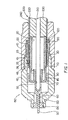
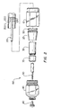
- FIG. 1 and FIG. 2 show a first embodiment of a coaxial connector according to the present invention.
- a first piece of the connector is comprised of a clamp nut 10 including a ferrule 20, a mandrel 30 and closing collar 70.
- a second piece of the connector is comprised of an entry body 40 having a pin terminal 50, a support insulator 60 and an actuator 80.
- a length of coaxial cable 200 is provided to the clamp nut 10 of coaxial connector 150.
- the coaxial cable has had one end prepared for having the connector assembled onto.
- the coaxial cable 200 has a length of centre conductor 210 exposed approximately flush to the face of the closing collar, thus there is no need to "measure" the preparation length, as may be required by other connectors.
- An additional section of cable insulator 230 approximately 1.2 inches in length, has been removed.
- an end most section of insulating jacket 240 approximately 0.5 inches in length, has been removed exposing the conductive sheath 220.
- Mandrel 30 is non-conductive, therefore it can be fabricated from non-conductive material, it can be comprised of a metal insert with a plastic surrounding or it can be comprised of metallized plastic. By implementing a non-conductive mandrel, the RF performance of the connector is improved, since the frequency resonance inherent in a metal version is not present. Mandrel 30 has closing collar 70, also non-conductive, attached at a distal end and is inserted into a front end of clamp nut 10.
- Clamp nut 10 is electrically conductive and is comprised of aluminium in this embodiment, although other conductive materials could be used. As the prepared end of coaxial cable 200 enters clamp nut 10, center conductor 210 is encircled by and extends beyond mandrel 30 and closing collar 70, and a large percentage of mandrel 30 itself is encircled by conductive sheath 220.
- Ferrule 20 is comprised of aluminium in this embodiment although other conductive materials could also be used, and is positioned so that when entry body 40 is integrated with clamp nut 10, the serrations 22 on a first step 25 of ferrule 20 will come into to contact with insulating jacket 240 of coaxial cable 200, and serrations 26 on a second step 28 of ferrule 20 will be brought into contact with conductive sheath 220.
- Entry body 40 is also electrically conductive and in this embodiment is comprised of aluminium, though other conductive materials could be used. Entry body 40 includes at a front end a support insulator 60 through which extends pin terminal 50. Pin terminal 50 has an open end which surrounds centre conductor 210. Support insulator 60 includes a plurality of serrated annular rings for sealing the pin terminal 50 to the support insulator 60.
- the connector 150 is assembled by integrating a rear end of entry body 40 into a front end of clamp nut 10.
- the cam surface 85 of actuator 80 is brought into contact with closing collar 70 and exerts force on closing collar 70 which in turn presses against pin terminal 50, causing the serrations 55 on an internal surface of pin terminal 50 to provide a secure mechanical and electrical connection between pin terminal 50 and centre conductor 210 of coaxial cable 200.
- the connection to centre conductor 210 provides maximum tensile force with a minimum of conductor damage.
- the closure of pin terminal 50 onto centre conductor 210 is self-limiting, and is insensitive to the degree of nut tightness, thereby providing a more consistent and repeatable closure process.
- front ends of ferrule 20 are forced inwards by the action of entry body internal shoulder 45 forcibly contacting the truncated conical exterior surface of ferrule 20, causing the serrations on the first step of the ferrule to press against insulating jacket 240. Accordingly, coaxial cable 200 is secured in place between the first step of ferrule 20 and mandrel 30. Additionally, as the front ends of ferrule 20 are forced inwards, the serrations on a second step of ferrule 20 are forced against conductive sheath 220 of coaxial cable 200 and mandrel 30.
- the conductive sheath 220 is uniformly gripped without deformation and weakening, as compared to prior art connectors, which can cause significant pleating of the conductive sheath.
- the closure of ferrule 20 onto the coaxial cable 200 is self-limiting, and is insensitive to the degree of nut tightness, thereby providing a more consistent and repeatable closure process. Accordingly, a secure electrical and mechanical connection between ferule 20 and conductive sheath 220 is produced.
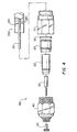
- FIG. 3 and Fig. 4 show a second embodiment of a coaxial connector according to the present invention.
- a first piece of the connector is comprised of a clamp nut 10 including a ferrule 20', a mandrel 30' having an integrated closing collar and a retaining ring 160.
- a second piece of the connector is comprised of an entry body 40 having a pin terminal 50, a support insulator 60 and an actuator 80.
- a length of coaxial cable 200 is provided to the clamp nut 10 of coaxial connector 150.
- the coaxial cable has had one end prepared for having the connector assembled onto.
- the coaxial cable 200 has a length of center conductor 210 exposed approximately flush to the face of the closing collar, thus there is no need to "measure" the preparation length, as may be required by other connectors.
- An additional section of cable insulator 230 approximately 1.2 inches in length, has been removed.
- an end most section of insulating jacket 240 approximately, .5 inches in length, has been removed exposing the conductive sheath 220.
- the prepared end of coaxial cable 200 is inserted into a rear end of clamp nut 10.
- the length of clamp nut 10 provides cable strain relief as well as providing RF leakage protection.
- Mandrel 30' is non-conductive in this embodiment, therefore it can be fabricated from non conductive material, it can be comprised of a metal insert with a plastic surrounding, or it can be comprised of metallized plastic. By implementing a non-conductive mandrel, the RF performance of the connector is improved, since the frequency resonance inherent in a metal version is not present.
- Clamp nut 10 is electrically conductive and is comprised of aluminum in this embodiment, although other conductive materials could be used.
- center conductor 210 is encircled by and extends beyond mandrel 30' and a portion of mandrel 30' itself is encircled by conductive sheath 220.
- Ferrule 20' is comprised of aluminum in this embodiment although other conductive materials could also be used, and is positioned so that when entry body 40 is integrated with clamp nut 10, the serrations on a first step of ferrule 20' will come into to contact with insulating jacket 240 of coaxial cable 200, and serrations on a second step of ferrule 20 will be brought into contact with conductive sheath 220.
- Entry body 40 is also electrically conductive and in this embodiment is comprised of aluminum, though other conductive materials could be used. Entry body 40 includes at a front end a support insulator 60 through which extends pin terminal 50. Pin terminal 50 has an open end which surrounds center conductor 210. Support insulator 60 includes a plurality of serrated annular rings (not shown) for sealing the pin terminal 50 to the support insulator 60.
- the connector 150 is assembled by integrating a rear end of entry body 40 into a front end of clamp nut 10.
- the cam surface 85 of actuator 80 is brought into contact with mandrel 30'.
- Actuator 80 exerts force on mandrel 30' which in turn presses against pin terminal 50, causing the serrations 55 on an internal surface of pin terminal 50 to provide a secure mechanical and electrical connection between pin terminal 50 and center conductor 210 of coaxial cable 200.
- the connection to the center conductor 210 provides maximum tensile force with a minimum of conductor damage.
- the closure of pin terminal 50 onto center conductor 210 is self-limiting, and is insensitive to the degree of nut tightness, thereby providing a more consistent and repeatable closure process.
- front ends of ferrule 20 are forced inwards by the action of entry body internal shoulder 45 forcibly contacting the cam surface of ferrule 20', causing the serrations on the first step of the ferrule to press against insulating jacket 240. Accordingly, coaxial cable 200 is secured in place between the first step of ferrule 20' and mandrel 30'. Additionally, as the front ends of ferrule 20' are forced inwards, the serrations on a second step of ferrule 20' are forced against conductive sheath 220 of coaxial cable 200 and mandrel 30'.
- the conductive sheath 220 is uniformly gripped without deformation and weakening, as compared to prior art connectors, which can cause significant pleating of the conductive sheath.
- the closure of ferrule 20' onto the coaxial cable 200 is self-limiting, and is insensitive to the degree of nut tightness, thereby providing a more consistent and repeatable closure process. Accordingly, a secure electrical and mechanical connection between ferrule 20' and conductive sheath 220 is produced.
- the closure of the ferrule 20 in the first embodiment, and ferule 20' in the second embodiment, onto the sheath 220 occurs before the closure of the pin terminal 50 onto the center conductor 210, in order to prevent distortion of the center conductor 210 due to excessive compressive load if the timing were otherwise.
- a "positive stop” design allows for visual observation of entry body 40 being completely received by clamp nut 10, and can be made by noticing that the external shoulder 48 of entry body 40 is abutting against clamp nut 10. Additionally, there is tactile feedback when torquing the clamp nut, thus there are two indications of full, complete assembly of the connector.
- O-ring carrier 90 Located within clamp nut 10 is an o-ring carrier 90.
- O-ring carrier 90 is comprised of tin-plated brass in this embodiment, though other conductive materials could be used.
- O-ring carrier 90 allows the ferrule 20 in the first embodiment, and ferule 20' in the second embodiment, to freely rotate while under axial compression, fixedly holding the coaxial cable 200 during rotation of the clamp nut 10.
- O-ring carrier 90 has an annular race for securing o-ring 100 between coaxial cable 200 and clamp nut 10. In this manner the o-rings provide for a reduction in the degradation of RF signal performance. Additionally, the o-rings serve to seal out contaminants that accelerate galvanic corrosion.
- O-ring 110 is provided between entry body 40 and clamp nut 10
- o-ring 130 is provided between support insulator 60 and entry body 40, to keep contaminants from entering the connector. Additionally, a seal is also accomplished between the pin terminal 50 and support insulator 60 by the serrated rings of support insulator 60 (not shown).
- O-ring 120 is provided around the outside of entry body 40 so that a moisture free connection can be made between the connector and its intended receiver.
- the o-rings are comprised of a material which provides ultra-violet light (UV) and ozone stability for maximum resistance to atmospheric ingress.
- UV ultra-violet light
- the connector is reusable on the same cable or on another cable.
- the connector is not "craft sensitive", nor is the connector dependent on installation technique. Additionally, the connectors's pull back distance is minimized which allows for easier disconnects after installation.
- the connector is a "positive release” design in that the closing collar is removed along with the clamp nut 10 during unmating of the connector, thereby preventing locking of the center conductor 210 within pin terminal 50.
- the present connector is more easily mated and unmated “live” than other designs, due to the protected center conductor 210 being contained within closing collar 70. This aspect is important since voltage and current levels are rising in cable systems.
- Another connector embodiment includes incorporating a ferrule and nut assembly that closes onto a non-jacketed cable.
- the present design is also expandable to include such applications as a flexible or drop cable, a splice connector, a feed through connector as well as including other cable sizes and types. While two piece connectors have been described in detail, three piece connectors, which also incorporate the design features described above could be implemented as well.
Abstract
Description
- The invention relates generally to electrical connectors, and more particularly to coaxial cable connectors used in conjunction with either semi-rigid coaxial cable or flexible coaxial cable.
- Coaxial cables typically consist of a central conductor which is surrounded by a metallic outer conductor. An insulator separates the central conductor from the outer conductor, and an insulating jacket covers the outer conductor. The outer conductor is usually in one of two forms, either a copper braid or an aluminum sheath.
- Coaxial cables of this type are used broadly, especially in cable television applications. The coaxial cable provides for high quality transportation of signals. In order to effectively use the cables, a connector must be fitted to at least one end of the cable. A connector, in order to be practical, must provide for a reliable mechanical and electrical connection as well as being simple to install and use. It is further desirable that the connector positively release the center conductor upon disassembly and that the connector hold the cable stationary during twisting of the clamp nut.
- United States patent No. 4,952,174 discloses a coaxial cable connector for use with a prepared end of a coaxial cable. The connector comprises a body and a nut threadably tightenable to the body. The nut defines an interior space including a mandrel assembly which is freely rotatable within the interior space until the nut is tightened to the body. The mandrel assembly includes an insulator cone for guiding the centre conductor and a clamping arrangement for engaging and clamping a centre pin chuck as the nut is tightened to the body. A mandrel is slidably mounted under the cable outer metal jacket in a space provided after removal of a portion of the dielectric core incident to preparation of the cable end. A ferrule is slidably mounted over the outer jacket and the ferrule includes collet fingers disposed over a portion of the mandrel. The mandrel closes the collet fingers to cause them to compress the outer metal jacket against a portion of the connector during the installation of the connector to the prepared cable end.
- The connector of US 4,952,174 uses a ferrule that moves relative to a mandrel shell to close the ferrule about the cable. The ferrule incorporates a plurality of times that are used to grip the conductive sheath. This implementation has the disadvantage that the tines may deform, pleat or weaken the conductive sheath and in addition do not grip the outermost insulator of the coaxial jacket. Further, the mandrel is composed of a metal sleeve, which allows a frequency response that is inherent with a metal mandrel, and can establish a parallel electrical contact with the contact established by the ferrule between the cable's conductive sheath and the connector body. Therefore, it would be desirable to reduce deformation of the conductive sheath, limit frequency resonance and assure only one conductive path between the conductive sheath and the connector body.
- The present invention provides a two piece coaxial cable connector comprising: a clamp nut open on each of two ends, said clamp nut defining an interior space, a first end of said clamp nut for receiving a coaxial cable, a portion of the interior space adjacent to a second end of said clamp nut having a mating area; an entry body defining an interior space, said entry body open on each end, a first end of said entry body having a mating area co-operating with the mating area of the clamp nut; a ferrule having a truncated conical exterior surface and a stepped interior surface, said ferrule centrally disposed along a common longitudinal axis within said clamp nut interior space, an outside surface of said ferrule abutting an end portion of said entry body; a mandrel centrally disposed within said ferrule along a common longitudinal axis, said mandrel engaging a first end of said ferrule; a closing collar centrally disposed about a common longitudinal axis with said clamp nut, a first end of said closing collar engaging a first end of said mandrel; a pin terminal centrally disposed along a common longitudinal axis within said entry body, a first end of said pin terminal extending beyond a second end of said entry body, said pin terminal having a bore partially disposed longitudinally therein at a second end, said pin terminal bore having a plurality of serrations on an interior surface adjacent said bore second end; a support insulator centrally disposed along a common longitudinal axis within a second end of said entry body, said support insulator having a bore centrally disposed therethrough for receiving said pin terminal; and an actuator centrally disposed along a common longitudinal axis within said entry body, said actuator having a cam shaped inner surface extending longitudinally therein, said actuator disposed so that said cam surface engages said closing collar.
- In addition, there may be o-rings placed between various parts of the connector to provide for sealing integrity and prevent RF performance degradation. As the connector pieces are mated together a secure connection between the connector and the coaxial cable is produced. The design is easily expandable to other variations including, but not limited to, a flexible drop cable, a splice connector, and a feed-through connector as well as being used in conjunction with other cable types and sizes.
- The invention will be more fully understood from the following detailed description taken in conjunction with the accompanying drawing in which:
- FIG. 1 is a cross-sectional view of a first embodiment of the connector;
- FIG. 2 is an exploded view of the connector of FIG: 1;
- FIG. 3 is a cross-sectional view of a second embodiment of the connector; and
- FIG. 4 is an exploded view of the connector of FIG. 3.
-
- FIG. 1 and FIG. 2 show a first embodiment of a coaxial connector according to the present invention. A first piece of the connector is comprised of a
clamp nut 10 including aferrule 20, amandrel 30 and closingcollar 70. A second piece of the connector is comprised of anentry body 40 having apin terminal 50, asupport insulator 60 and anactuator 80. - In this embodiment a length of
coaxial cable 200 is provided to theclamp nut 10 ofcoaxial connector 150. The coaxial cable has had one end prepared for having the connector assembled onto. As a result of the preparation of an end, thecoaxial cable 200 has a length ofcentre conductor 210 exposed approximately flush to the face of the closing collar, thus there is no need to "measure" the preparation length, as may be required by other connectors. An additional section ofcable insulator 230, approximately 1.2 inches in length, has been removed. Additionally, an end most section of insulatingjacket 240, approximately 0.5 inches in length, has been removed exposing theconductive sheath 220. - The prepared end of
coaxial cable 200 is inserted into a rear end ofclamp nut 10. The length ofclamp nut 10 provides cable strain relief as well as providing RF leakage protection. Mandrel 30 is non-conductive, therefore it can be fabricated from non-conductive material, it can be comprised of a metal insert with a plastic surrounding or it can be comprised of metallized plastic. By implementing a non-conductive mandrel, the RF performance of the connector is improved, since the frequency resonance inherent in a metal version is not present. Mandrel 30 has closingcollar 70, also non-conductive, attached at a distal end and is inserted into a front end ofclamp nut 10.Clamp nut 10 is electrically conductive and is comprised of aluminium in this embodiment, although other conductive materials could be used. As the prepared end ofcoaxial cable 200 entersclamp nut 10,center conductor 210 is encircled by and extends beyondmandrel 30 and closingcollar 70, and a large percentage ofmandrel 30 itself is encircled byconductive sheath 220. - An end of
mandrel 30 not surrounded byconductive sheath 220 is engaged with an end offerrule 20.Ferrule 20 is comprised of aluminium in this embodiment although other conductive materials could also be used, and is positioned so that whenentry body 40 is integrated withclamp nut 10, theserrations 22 on afirst step 25 offerrule 20 will come into to contact withinsulating jacket 240 ofcoaxial cable 200, and serrations 26 on asecond step 28 offerrule 20 will be brought into contact withconductive sheath 220. -
Entry body 40 is also electrically conductive and in this embodiment is comprised of aluminium, though other conductive materials could be used.Entry body 40 includes at a front end asupport insulator 60 through which extendspin terminal 50.Pin terminal 50 has an open end which surroundscentre conductor 210.Support insulator 60 includes a plurality of serrated annular rings for sealing thepin terminal 50 to thesupport insulator 60. - The
connector 150 is assembled by integrating a rear end ofentry body 40 into a front end ofclamp nut 10. As a result ofentry body 40 being integrated withclamp nut 10, thecam surface 85 ofactuator 80 is brought into contact withclosing collar 70 and exerts force onclosing collar 70 which in turn presses againstpin terminal 50, causing theserrations 55 on an internal surface ofpin terminal 50 to provide a secure mechanical and electrical connection betweenpin terminal 50 andcentre conductor 210 ofcoaxial cable 200. The connection tocentre conductor 210 provides maximum tensile force with a minimum of conductor damage. The closure ofpin terminal 50 ontocentre conductor 210 is self-limiting, and is insensitive to the degree of nut tightness, thereby providing a more consistent and repeatable closure process. - As the rear end of
entry body 40 enters the front end ofclamp nut 10, front ends offerrule 20 are forced inwards by the action of entry bodyinternal shoulder 45 forcibly contacting the truncated conical exterior surface offerrule 20, causing the serrations on the first step of the ferrule to press against insulatingjacket 240. Accordingly,coaxial cable 200 is secured in place between the first step offerrule 20 andmandrel 30. Additionally, as the front ends offerrule 20 are forced inwards, the serrations on a second step offerrule 20 are forced againstconductive sheath 220 ofcoaxial cable 200 andmandrel 30. Theconductive sheath 220 is uniformly gripped without deformation and weakening, as compared to prior art connectors, which can cause significant pleating of the conductive sheath. The closure offerrule 20 onto thecoaxial cable 200 is self-limiting, and is insensitive to the degree of nut tightness, thereby providing a more consistent and repeatable closure process. Accordingly, a secure electrical and mechanical connection betweenferule 20 andconductive sheath 220 is produced. - Fig. 3 and Fig. 4 show a second embodiment of a coaxial connector according to the present invention. A first piece of the connector is comprised of a
clamp nut 10 including a ferrule 20', a mandrel 30' having an integrated closing collar and a retaining ring 160. A second piece of the connector is comprised of anentry body 40 having apin terminal 50, asupport insulator 60 and anactuator 80. - In this second embodiment a length of
coaxial cable 200 is provided to theclamp nut 10 ofcoaxial connector 150. The coaxial cable has had one end prepared for having the connector assembled onto. As a result of the preparation of an end, thecoaxial cable 200 has a length ofcenter conductor 210 exposed approximately flush to the face of the closing collar, thus there is no need to "measure" the preparation length, as may be required by other connectors. An additional section ofcable insulator 230, approximately 1.2 inches in length, has been removed. Additionally, an end most section of insulatingjacket 240, approximately, .5 inches in length, has been removed exposing theconductive sheath 220. - The prepared end of
coaxial cable 200 is inserted into a rear end ofclamp nut 10. The length ofclamp nut 10 provides cable strain relief as well as providing RF leakage protection. Mandrel 30' is non-conductive in this embodiment, therefore it can be fabricated from non conductive material, it can be comprised of a metal insert with a plastic surrounding, or it can be comprised of metallized plastic. By implementing a non-conductive mandrel, the RF performance of the connector is improved, since the frequency resonance inherent in a metal version is not present.Clamp nut 10 is electrically conductive and is comprised of aluminum in this embodiment, although other conductive materials could be used. As the prepared end ofcoaxial cable 200 entersclamp nut 20,center conductor 210 is encircled by and extends beyond mandrel 30' and a portion of mandrel 30' itself is encircled byconductive sheath 220. - A section of mandrel 30' not surrounded by
conductive sheath 220 is engaged with an end offerrule 20. Ferrule 20' is comprised of aluminum in this embodiment although other conductive materials could also be used, and is positioned so that whenentry body 40 is integrated withclamp nut 10, the serrations on a first step of ferrule 20' will come into to contact with insulatingjacket 240 ofcoaxial cable 200, and serrations on a second step offerrule 20 will be brought into contact withconductive sheath 220. -
Entry body 40 is also electrically conductive and in this embodiment is comprised of aluminum, though other conductive materials could be used.Entry body 40 includes at a front end asupport insulator 60 through which extendspin terminal 50.Pin terminal 50 has an open end which surroundscenter conductor 210.Support insulator 60 includes a plurality of serrated annular rings (not shown) for sealing thepin terminal 50 to thesupport insulator 60. - The
connector 150 is assembled by integrating a rear end ofentry body 40 into a front end ofclamp nut 10. As a result ofentry body 40 being integrated withclamp nut 10, thecam surface 85 ofactuator 80 is brought into contact with mandrel 30'.Actuator 80 exerts force on mandrel 30' which in turn presses againstpin terminal 50, causing theserrations 55 on an internal surface ofpin terminal 50 to provide a secure mechanical and electrical connection betweenpin terminal 50 andcenter conductor 210 ofcoaxial cable 200. The connection to thecenter conductor 210 provides maximum tensile force with a minimum of conductor damage. The closure ofpin terminal 50 ontocenter conductor 210 is self-limiting, and is insensitive to the degree of nut tightness, thereby providing a more consistent and repeatable closure process. - As the rear end of
entry body 40 enters the front end ofclamp nut 10, front ends offerrule 20 are forced inwards by the action of entry bodyinternal shoulder 45 forcibly contacting the cam surface of ferrule 20', causing the serrations on the first step of the ferrule to press against insulatingjacket 240. Accordingly,coaxial cable 200 is secured in place between the first step of ferrule 20' and mandrel 30'. Additionally, as the front ends of ferrule 20' are forced inwards, the serrations on a second step of ferrule 20' are forced againstconductive sheath 220 ofcoaxial cable 200 and mandrel 30'. Theconductive sheath 220 is uniformly gripped without deformation and weakening, as compared to prior art connectors, which can cause significant pleating of the conductive sheath. The closure of ferrule 20' onto thecoaxial cable 200 is self-limiting, and is insensitive to the degree of nut tightness, thereby providing a more consistent and repeatable closure process. Accordingly, a secure electrical and mechanical connection between ferrule 20' andconductive sheath 220 is produced. - It is important to note the "timing" of the closure of the connector with the coaxial cable. The closure of the
ferrule 20 in the first embodiment, and ferule 20' in the second embodiment, onto thesheath 220 occurs before the closure of thepin terminal 50 onto thecenter conductor 210, in order to prevent distortion of thecenter conductor 210 due to excessive compressive load if the timing were otherwise. - A "positive stop" design allows for visual observation of
entry body 40 being completely received byclamp nut 10, and can be made by noticing that theexternal shoulder 48 ofentry body 40 is abutting againstclamp nut 10. Additionally, there is tactile feedback when torquing the clamp nut, thus there are two indications of full, complete assembly of the connector. - Protection against contaminates and a reduction of the degradation of RF signals are provided. Located within
clamp nut 10 is an o-ring carrier 90. O-ring carrier 90 is comprised of tin-plated brass in this embodiment, though other conductive materials could be used. O-ring carrier 90 allows theferrule 20 in the first embodiment, and ferule 20' in the second embodiment, to freely rotate while under axial compression, fixedly holding thecoaxial cable 200 during rotation of theclamp nut 10. O-ring carrier 90 has an annular race for securing o-ring 100 betweencoaxial cable 200 and clampnut 10. In this manner the o-rings provide for a reduction in the degradation of RF signal performance. Additionally, the o-rings serve to seal out contaminants that accelerate galvanic corrosion. O-ring 110 is provided betweenentry body 40 and clampnut 10, and o-ring 130 is provided betweensupport insulator 60 andentry body 40, to keep contaminants from entering the connector. Additionally, a seal is also accomplished between thepin terminal 50 andsupport insulator 60 by the serrated rings of support insulator 60 (not shown). O-ring 120 is provided around the outside ofentry body 40 so that a moisture free connection can be made between the connector and its intended receiver. - The o-rings are comprised of a material which provides ultra-violet light (UV) and ozone stability for maximum resistance to atmospheric ingress.
- With such a design, the connector is reusable on the same cable or on another cable. The connector is not "craft sensitive", nor is the connector dependent on installation technique. Additionally, the connectors's pull back distance is minimized which allows for easier disconnects after installation. The connector is a "positive release" design in that the closing collar is removed along with the
clamp nut 10 during unmating of the connector, thereby preventing locking of thecenter conductor 210 withinpin terminal 50. The present connector is more easily mated and unmated "live" than other designs, due to the protectedcenter conductor 210 being contained within closingcollar 70. This aspect is important since voltage and current levels are rising in cable systems. - Another connector embodiment includes incorporating a ferrule and nut assembly that closes onto a non-jacketed cable. The present design is also expandable to include such applications as a flexible or drop cable, a splice connector, a feed through connector as well as including other cable sizes and types. While two piece connectors have been described in detail, three piece connectors, which also incorporate the design features described above could be implemented as well.
- Having described preferred embodiments of the invention it will now become apparent to those of ordinary skill in the art that other embodiments incorporating these concepts may be used. Accordingly, it is submitted that the invention should not be limited to the described embodiments but rather should be limited only by the scope of the appended claims.
Claims (18)
- A two piece coaxial cable connector (150) comprising:a clamp nut (10) open on each of two ends, said clamp nut (10) defining an interior space, a first end of said clamp nut (10) for receiving a coaxial cable (200), a portion of the interior space adjacent to a second end of said clamp nut (10) having a mating area;an entry body (40) defining an interior space, said entry body (40) open on each end, a first end of said entry body (40) having a mating area co-operating with the mating area of the clamp nut (10);a ferrule (20) having a truncated conical exterior surface and a stepped interior surface (25, 26), said ferrule (20) centrally disposed along a common longitudinal axis within said clamp nut (10) interior space, an outside surface of said ferrule (20) abutting an end portion (45) of said entry body (40);a mandrel (30) centrally disposed within said ferrule (20) along a common longitudinal axis, said mandrel (30) engaging a first end of said ferrule (20);a closing collar (70) centrally disposed about a common longitudinal axis with said clamp nut (10), a first end of said closing collar (70) engaging a first end of said mandrel (30);a pin terminal (50) centrally disposed along a common longitudinal axis within said entry body (40), a first end of said pin terminal (50) extending beyond a second end of said entry body (40), said pin terminal (50) having a bore partially disposed longitudinally therein at a second end, said pin terminal bore having a plurality of serrations (55) on an interior surface adjacent said bore second end;a support insulator (60) centrally disposed along a common longitudinal axis within a second end of said entry body (40), said support insulator (60) having a bore centrally disposed therethrough for receiving said pin terminal (50); andan actuator (80) centrally disposed along a common longitudinal axis within said entry body (40), said actuator (80) having a cam shaped inner surface (85) extending longitudinally therein, said actuator (80) disposed so that said cam surface (85) engages said closing collar (70).
- The coaxial connector (150) of claim 1 wherein a first step (25) of said interior surface includes a first plurality of annular serrations (22), a second step (28) of said interior surface includes a second plurality of annular serrations (26), said first plurality of serrations (22) gripping an exterior insulating jacket (240) of the coaxial cable (200), said second plurality of serrations (26) providing electrical connections with a conductive sheath (220) of the coaxial cable (200) by movement of said first end of said entry body (40) along said truncated conical exterior surface of said ferrule (20) when said entry body (40) is integrated with said clamp nut (10).
- A two piece coaxial cable connector (150) comprising:a clamp nut (10) open on each of two ends, said clamp nut (10) defining an interior space, a first end of said clamp nut (10) for receiving a coaxial cable (200), a portion of the interior space adjacent to a second end of said clamp nut (10) having a mating area;an entry body (40) defining an interior space, said entry body (40) open on each end, a first end of said entry body (40) having a mating area cooperating with the mating area of the clamp nut (10);a ferrule (20') having a stepped exterior surface including a cam section (28) for engaging the entry body (40), said ferrule (20') centrally disposed along a common longitudinal axis within said clamp nut (10) interior space, an outside surface of said ferrule (20') abutting an end portion (45) of said entry body (40);a mandrel (30') centrally disposed within said ferrule (20') along a common longitudinal axis, said mandrel (30') engaging a first end of said ferrule (20'), said mandrel (30') including a closing collar (70);a pin terminal (50) centrally disposed along a common longitudinal axis within said entry body (40), a first end of said pin terminal (50) extending beyond a second end of said entry body (40), said pin terminal (50) having a bore partially disposed longitudinally therein at a second end, said pin terminal bore having a plurality of serrations (55) on an interior surface adjacent said bore second end;a support insulator (60) centrally disposed along a common longitudinal axis within a second end of said entry body (40), said support insulator (60) having a bore centrally disposed therethrough for receiving said pin terminal (50); andan actuator (80) centrally disposed along a common longitudinal axis within said entry body (40), said actuator (80) having a cam shaped inner surface (85) extending longitudinally therein, said actuator (80) disposed so that said cam surface (85) engages said closing collar (70).
- The coaxial connector (150) of claim 3 wherein said ferrule (20') has a stepped interior surface, a first step (25) of said interior surface including a first plurality of annular serrations (22), a second step of said interior surface including a second plurality of annular serrations (26), said first plurality of serrations (22) gripping an exterior insulating jacket (240) of the coaxial cable (200), said second plurality of serrations (26) providing electrical connections with a conductive sheath (220) of the coaxial cable (200) by movement of said first end of said entry body (40) along a cam section (28) of said exterior surface of said ferrule (20') when said entry body (40) is integrated with said clamp nut (10).
- The coaxial connector (150) of claim 1 or claim 3 wherein said pin terminal serrations (55) are forced into electrical connections with a central conductor (210) of the coaxial cable (200) when said entry body (40) is integrated with said clamp nut (10).
- The coaxial connector (150) of claim 1 or claim 3 wherein a visual sign of complete mating of said entry body (40) to said clamp nut (10) is provided by a shoulder (48) of said entry body (40) abutting against said second end of said clamp nut (10).
- The coaxial connector (150) of claim 1 or claim 3 further comprising an o-ring holder (90) centrally disposed along a common longitudinal axis within said clamp nut (10), said o-ring holder (90) adjacent to a second end of said ferrule (20, 20'), said o-ring holder (90) having an annular race disposed about an outside surface thereof.
- The coaxial connector (150) of claim 7 further including a first o-ring (100) disposed within said annular race of said o-ring holder (90).
- The coaxial connector (150) of claim 1 or claim 3 further comprising:a second o-ring (130) disposed between an outside surface of said support insulator (60) and an inside surface of said entry body (40);a third o-ring (1 10) disposed between an outside surface of said entry body (40) and an inside surface of said clamp nut (10); anda fourth o-ring (120) disposed about an external surface of said entry body (40).
- The coaxial connector (150) of claim 1 or claim 3 wherein said entry body (40), said ferrule (20, 20'), said clamp nut (10), and said pin terminal (50) are electrically conductive.
- The coaxial connector (150) of claim 1 or claim 3 wherein said entry body (40), said ferrule (20, 20') and said clamp nut (10) are comprised of aluminium; and said pin terminal (50) is comprised of tin-plated brass, silver-plated brass or other copper alloy.
- The coaxial connector (150) of claim 1 or claim 3 wherein said mandrel (30, 30'), said closing collar (70), said actuator (80), and said support insulator (60) are comprised of an electrically insulating material.
- The coaxial connector (150) of claim 1 or claim 3 wherein said mandrel (30, 30'), said actuator (80), and said support insulator (60) are comprised of an electrically insulating material.
- The coaxial connector (150) of claim 1 or claim 3 wherein said mandrel (30, 30') comprises a metal insert surrounded by plastic.
- The coaxial connector (150) of claim 1 or claim 3 wherein said mandrel (30, 30') comprises metallized plastic.
- The coaxial connector (150) of claim 1 or claim 3 wherein closing of said ferrule (20, 20') is self-limiting and independent of nut closure position.
- The coaxial connector (150) of claim 1 or claim 3 wherein closing of said pin terminal (50) is self-limiting and independent of nut closure position.
- The coaxial connector (150) of claim 1 or claim 3 wherein said ferrule (20, 20') has an interior surface including a plurality of annular serrations (22, 26), said plurality of serrations (22, 26) providing electrical connections with a conductive sheath (220) of the coaxial cable (200) by movement of said first end of said entry body (40) along said exterior surface of said ferrule (20, 20') when said entry body (40) is integrated with said clamp nut (10).
Applications Claiming Priority (3)
| Application Number | Priority Date | Filing Date | Title |
|---|---|---|---|
| US569582 | 1995-12-08 | ||
| US08/569,582 US5651698A (en) | 1995-12-08 | 1995-12-08 | Coaxial cable connector |
| PCT/US1996/016878 WO1997022162A1 (en) | 1995-12-08 | 1996-10-21 | Coaxial cable connector |
Publications (3)
| Publication Number | Publication Date |
|---|---|
| EP0809872A1 EP0809872A1 (en) | 1997-12-03 |
| EP0809872A4 EP0809872A4 (en) | 2000-01-26 |
| EP0809872B1 true EP0809872B1 (en) | 2004-12-22 |
Family
ID=24276021
Family Applications (1)
| Application Number | Title | Priority Date | Filing Date |
|---|---|---|---|
| EP96936809A Expired - Lifetime EP0809872B1 (en) | 1995-12-08 | 1996-10-21 | Coaxial cable connector |
Country Status (5)
| Country | Link |
|---|---|
| US (1) | US5651698A (en) |
| EP (1) | EP0809872B1 (en) |
| AU (1) | AU720115B2 (en) |
| DE (1) | DE69634076T2 (en) |
| WO (1) | WO1997022162A1 (en) |
Families Citing this family (155)
| Publication number | Priority date | Publication date | Assignee | Title |
|---|---|---|---|---|
| US5769662A (en) * | 1996-04-09 | 1998-06-23 | Augat Inc. | Snap together coaxial cable connector for use with polyethylene jacketed cable |
| US5788535A (en) * | 1996-09-11 | 1998-08-04 | Augat/Lrc Electronics, Inc. | Adaptor assembly |
| WO1998018179A1 (en) | 1996-10-23 | 1998-04-30 | Thomas & Betts International, Inc. | Coaxial cable connector |
| US6102738A (en) * | 1997-08-05 | 2000-08-15 | Thomas & Betts International, Inc. | Hardline CATV power connector |
| US6019636A (en) * | 1998-10-20 | 2000-02-01 | Eagle Comtronics, Inc. | Coaxial cable connector |
| EP0975051A1 (en) * | 1998-07-24 | 2000-01-26 | Cabel-Con A/S | Connector for coaxial cable with multiple start threads |
| ATE286310T1 (en) * | 1998-10-13 | 2005-01-15 | Cabel Con As | CONNECTOR FOR COAXIAL CABLES WITH FRICTION LOCK |
| US6210222B1 (en) | 1999-12-13 | 2001-04-03 | Eagle Comtronics, Inc. | Coaxial cable connector |
| USD432993S (en) * | 1999-12-20 | 2000-10-31 | John Mezzalingua Associates, Inc. | Filter nut for a high-pass filter assembly |
| EP1122835A1 (en) * | 2000-02-04 | 2001-08-08 | Cabel-Con A/S | One piece connector |
| US6309251B1 (en) * | 2000-06-01 | 2001-10-30 | Antronix, Inc. | Auto-seizing coaxial cable port for an electrical device |
| US6352448B1 (en) * | 2000-09-08 | 2002-03-05 | Randall A. Holliday | Cable TV end connector starter guide |
| US6331123B1 (en) | 2000-11-20 | 2001-12-18 | Thomas & Betts International, Inc. | Connector for hard-line coaxial cable |
| USD462327S1 (en) | 2001-09-28 | 2002-09-03 | John Mezzalingua Associates, Inc. | Co-axial cable connector |
| US6439924B1 (en) | 2001-10-11 | 2002-08-27 | Corning Gilbert Inc. | Solder-on connector for coaxial cable |
| US6544062B1 (en) | 2002-02-19 | 2003-04-08 | Huber & Suhner, Inc. | Connector array with connectors having outer surfaces in gear-to-gear contact |
| US6634906B1 (en) * | 2002-04-01 | 2003-10-21 | Min Hwa Yeh | Coaxial connector |
| CA2428893C (en) * | 2002-05-31 | 2007-12-18 | Thomas & Betts International, Inc. | Connector for hard-line coaxial cable |
| US6769933B2 (en) | 2002-11-27 | 2004-08-03 | Corning Gilbert Inc. | Coaxial cable connector and related methods |
| US6712631B1 (en) | 2002-12-04 | 2004-03-30 | Timothy L. Youtsey | Internally locking coaxial connector |
| US6805583B2 (en) * | 2002-12-06 | 2004-10-19 | Randall A. Holliday | Mini-coax cable connector and method of installation |
| US6935892B2 (en) * | 2002-12-06 | 2005-08-30 | Randall A. Holliday | Adapter for mini-coaxial cable |
| US7241164B2 (en) * | 2002-12-06 | 2007-07-10 | International Communication Manufacturing Corporation | Termination assembly for mini-coaxial cable having color-coded insulator |
| US7156695B2 (en) * | 2002-12-06 | 2007-01-02 | Holliday Randall A | Adapter for coaxial cable with interchangeable color bands |
| US6733336B1 (en) * | 2003-04-03 | 2004-05-11 | John Mezzalingua Associates, Inc. | Compression-type hard-line connector |
| US6773303B1 (en) * | 2003-04-30 | 2004-08-10 | Gih Sheng Co., Ltd. | Coaxial cable having easily attached coupler |
| US7264503B2 (en) * | 2003-07-07 | 2007-09-04 | John Mezzalingua Associates, Inc. | Sealing assembly for a port at which a cable is connected and method of connecting a cable to a port using the sealing assembly |
| US6994587B2 (en) * | 2003-07-23 | 2006-02-07 | Andrew Corporation | Coaxial cable connector installable with common tools |
| EP1501159A1 (en) * | 2003-07-23 | 2005-01-26 | Andrew Corporation | Coaxial cable connector installable with common tools |
| US7059900B2 (en) * | 2004-07-06 | 2006-06-13 | Holliday Randall A | Coaxial cable splice connector assemblies |
| US7048578B2 (en) * | 2003-10-14 | 2006-05-23 | Thomas & Betts International, Inc. | Tooless coaxial connector |
| US7261581B2 (en) * | 2003-12-01 | 2007-08-28 | Corning Gilbert Inc. | Coaxial connector and method |
| US6808415B1 (en) | 2004-01-26 | 2004-10-26 | John Mezzalingua Associates, Inc. | Clamping and sealing mechanism with multiple rings for cable connector |
| US7329149B2 (en) * | 2004-01-26 | 2008-02-12 | John Mezzalingua Associates, Inc. | Clamping and sealing mechanism with multiple rings for cable connector |
| US7108547B2 (en) * | 2004-06-10 | 2006-09-19 | Corning Gilbert Inc. | Hardline coaxial cable connector |
| US6955562B1 (en) * | 2004-06-15 | 2005-10-18 | Corning Gilbert Inc. | Coaxial connector with center conductor seizure |
| US7186127B2 (en) * | 2004-06-25 | 2007-03-06 | John Mezzalingua Associates, Inc. | Nut seal assembly for coaxial connector |
| US7500874B2 (en) * | 2004-06-25 | 2009-03-10 | John Mezzalingua Associates, Inc. | Nut seal assembly for coaxial cable system components |
| US7326079B2 (en) * | 2004-07-06 | 2008-02-05 | Rhps Ventures, Llc | Mini-coaxial cable splice connector assemblies and wall mount installation tool therefor |
| US7029326B2 (en) | 2004-07-16 | 2006-04-18 | John Mezzalingua Associates, Inc. | Compression connector for coaxial cable |
| US7131868B2 (en) * | 2004-07-16 | 2006-11-07 | John Mezzalingua Associates, Inc. | Compression connector for coaxial cable |
| US7048579B2 (en) * | 2004-07-16 | 2006-05-23 | John Mezzalingua Associates, Inc. | Compression connector for coaxial cable |
| US9281637B2 (en) | 2004-08-27 | 2016-03-08 | Ppc Broadband, Inc. | Mini coax cable connector |
| US7011547B1 (en) * | 2004-11-19 | 2006-03-14 | Golden Loch Industrial Co., Ltd. | Connector of coaxial cables |
| US20060110977A1 (en) | 2004-11-24 | 2006-05-25 | Roger Matthews | Connector having conductive member and method of use thereof |
| US8157589B2 (en) | 2004-11-24 | 2012-04-17 | John Mezzalingua Associates, Inc. | Connector having a conductively coated member and method of use thereof |
| DE202004018907U1 (en) * | 2004-12-06 | 2005-03-31 | Coninvers Elektronische Bauele | Contacting device for a cable shield |
| US7077700B2 (en) * | 2004-12-20 | 2006-07-18 | Corning Gilbert Inc. | Coaxial connector with back nut clamping ring |
| US7114990B2 (en) | 2005-01-25 | 2006-10-03 | Corning Gilbert Incorporated | Coaxial cable connector with grounding member |
| US7354309B2 (en) * | 2005-11-30 | 2008-04-08 | John Mezzalingua Associates, Inc. | Nut seal assembly for coaxial cable system components |
| US7189114B1 (en) | 2006-06-29 | 2007-03-13 | Corning Gilbert Inc. | Compression connector |
| JP4899735B2 (en) * | 2006-09-13 | 2012-03-21 | 富士通株式会社 | Coaxial connector and manufacturing method thereof, superconducting device and manufacturing method thereof |
| US20080081512A1 (en) * | 2006-10-03 | 2008-04-03 | Shawn Chawgo | Coaxial Cable Connector With Threaded Post |
| US7632141B2 (en) * | 2007-02-22 | 2009-12-15 | John Mezzalingua Associates, Inc. | Compact compression connector with attached moisture seal |
| US7458850B1 (en) * | 2007-05-23 | 2008-12-02 | Corning Gilbert Inc. | Right-angled coaxial cable connector |
| US7425153B1 (en) * | 2007-09-25 | 2008-09-16 | D'addario & Company, Inc. | Electronic connector |
| US8834200B2 (en) | 2007-12-17 | 2014-09-16 | Perfectvision Manufacturing, Inc. | Compression type coaxial F-connector with traveling seal and grooved post |
| US7740502B2 (en) * | 2007-12-21 | 2010-06-22 | Commscope, Inc. Of North Carolina | Reuseable coaxial connectors and related methods |
| US8171629B2 (en) | 2007-12-21 | 2012-05-08 | Commscope Inc. Of North Carolina | Reuseable coaxial connector method |
| EP2149937B1 (en) * | 2008-08-01 | 2013-01-09 | PPC, A Division of John Mezzalingua Associates, Inc. | Coaxial connector and method for connecting the coaxial connector to a mating component |
| US8113875B2 (en) | 2008-09-30 | 2012-02-14 | Belden Inc. | Cable connector |
| US8025518B2 (en) | 2009-02-24 | 2011-09-27 | Corning Gilbert Inc. | Coaxial connector with dual-grip nut |
| US8029315B2 (en) | 2009-04-01 | 2011-10-04 | John Mezzalingua Associates, Inc. | Coaxial cable connector with improved physical and RF sealing |
| US7824216B2 (en) | 2009-04-02 | 2010-11-02 | John Mezzalingua Associates, Inc. | Coaxial cable continuity connector |
| US20100275341A1 (en) * | 2009-04-29 | 2010-11-04 | Ansell Healthcare Products Llc | Knitted Glove Having A Single Layer With A Plurality Of Yarns |
| US7892005B2 (en) | 2009-05-19 | 2011-02-22 | John Mezzalingua Associates, Inc. | Click-tight coaxial cable continuity connector |
| US9017101B2 (en) | 2011-03-30 | 2015-04-28 | Ppc Broadband, Inc. | Continuity maintaining biasing member |
| US8444445B2 (en) | 2009-05-22 | 2013-05-21 | Ppc Broadband, Inc. | Coaxial cable connector having electrical continuity member |
| US8573996B2 (en) | 2009-05-22 | 2013-11-05 | Ppc Broadband, Inc. | Coaxial cable connector having electrical continuity member |
| US8287320B2 (en) | 2009-05-22 | 2012-10-16 | John Mezzalingua Associates, Inc. | Coaxial cable connector having electrical continuity member |
| US9570845B2 (en) | 2009-05-22 | 2017-02-14 | Ppc Broadband, Inc. | Connector having a continuity member operable in a radial direction |
| WO2011021297A1 (en) * | 2009-08-20 | 2011-02-24 | 行田電線株式会社 | Waterproof connector |
| US8272893B2 (en) | 2009-11-16 | 2012-09-25 | Corning Gilbert Inc. | Integrally conductive and shielded coaxial cable connector |
| US8468688B2 (en) | 2010-04-02 | 2013-06-25 | John Mezzalingua Associates, LLC | Coaxial cable preparation tools |
| US7934954B1 (en) | 2010-04-02 | 2011-05-03 | John Mezzalingua Associates, Inc. | Coaxial cable compression connectors |
| US8177582B2 (en) | 2010-04-02 | 2012-05-15 | John Mezzalingua Associates, Inc. | Impedance management in coaxial cable terminations |
| US9166306B2 (en) | 2010-04-02 | 2015-10-20 | John Mezzalingua Associates, LLC | Method of terminating a coaxial cable |
| TWI549386B (en) | 2010-04-13 | 2016-09-11 | 康寧吉伯特公司 | Coaxial connector with inhibited ingress and improved grounding |
| US8172608B2 (en) | 2010-04-29 | 2012-05-08 | Commscope Inc. Of North Carolina | Reuseable coaxial connectors and related extraction tools and methods |
| US8882520B2 (en) | 2010-05-21 | 2014-11-11 | Pct International, Inc. | Connector with a locking mechanism and a movable collet |
| US8419468B2 (en) * | 2010-06-16 | 2013-04-16 | Commscope, Inc. Of North Carolina | Coaxial connectors having backwards compatability with F-style female connector ports and related female connector ports, adapters and methods |
| US8730639B1 (en) | 2010-07-13 | 2014-05-20 | Raycap, S.A. | Overvoltage protection for remote radio head-based wireless communication systems |
| US11251608B2 (en) | 2010-07-13 | 2022-02-15 | Raycap S.A. | Overvoltage protection system for wireless communication systems |
| US8995106B2 (en) | 2011-02-08 | 2015-03-31 | Raycap, S.A. | Overvoltage protection system for wireless communication systems |
| US8526200B2 (en) * | 2010-07-13 | 2013-09-03 | Raycap, S.A. | Connection lug |
| US8079860B1 (en) | 2010-07-22 | 2011-12-20 | John Mezzalingua Associates, Inc. | Cable connector having threaded locking collet and nut |
| US8152551B2 (en) | 2010-07-22 | 2012-04-10 | John Mezzalingua Associates, Inc. | Port seizing cable connector nut and assembly |
| US8113879B1 (en) | 2010-07-27 | 2012-02-14 | John Mezzalingua Associates, Inc. | One-piece compression connector body for coaxial cable connector |
| US8888526B2 (en) | 2010-08-10 | 2014-11-18 | Corning Gilbert, Inc. | Coaxial cable connector with radio frequency interference and grounding shield |
| US8579658B2 (en) | 2010-08-20 | 2013-11-12 | Timothy L. Youtsey | Coaxial cable connectors with washers for preventing separation of mated connectors |
| US8167636B1 (en) | 2010-10-15 | 2012-05-01 | John Mezzalingua Associates, Inc. | Connector having a continuity member |
| US8323053B2 (en) | 2010-10-18 | 2012-12-04 | John Mezzalingua Associates, Inc. | Connector having a constant contact nut |
| US8167635B1 (en) | 2010-10-18 | 2012-05-01 | John Mezzalingua Associates, Inc. | Dielectric sealing member and method of use thereof |
| US8075338B1 (en) | 2010-10-18 | 2011-12-13 | John Mezzalingua Associates, Inc. | Connector having a constant contact post |
| US8167646B1 (en) | 2010-10-18 | 2012-05-01 | John Mezzalingua Associates, Inc. | Connector having electrical continuity about an inner dielectric and method of use thereof |
| TWI558022B (en) | 2010-10-27 | 2016-11-11 | 康寧吉伯特公司 | Push-on cable connector with a coupler and retention and release mechanism |
| US8337229B2 (en) | 2010-11-11 | 2012-12-25 | John Mezzalingua Associates, Inc. | Connector having a nut-body continuity element and method of use thereof |
| US8341838B2 (en) * | 2010-11-22 | 2013-01-01 | Andrew Llc | Method of installing a coaxial cable into an electrical connector |
| US8414322B2 (en) | 2010-12-14 | 2013-04-09 | Ppc Broadband, Inc. | Push-on CATV port terminator |
| US8398421B2 (en) | 2011-02-01 | 2013-03-19 | John Mezzalingua Associates, Inc. | Connector having a dielectric seal and method of use thereof |
| US8157588B1 (en) | 2011-02-08 | 2012-04-17 | Belden Inc. | Cable connector with biasing element |
| US8465322B2 (en) | 2011-03-25 | 2013-06-18 | Ppc Broadband, Inc. | Coaxial cable connector |
| US8342879B2 (en) | 2011-03-25 | 2013-01-01 | John Mezzalingua Associates, Inc. | Coaxial cable connector |
| US8366481B2 (en) | 2011-03-30 | 2013-02-05 | John Mezzalingua Associates, Inc. | Continuity maintaining biasing member |
| US8388377B2 (en) | 2011-04-01 | 2013-03-05 | John Mezzalingua Associates, Inc. | Slide actuated coaxial cable connector |
| US8348697B2 (en) | 2011-04-22 | 2013-01-08 | John Mezzalingua Associates, Inc. | Coaxial cable connector having slotted post member |
| KR101139943B1 (en) * | 2011-05-12 | 2012-04-30 | 한국전자통신연구원 | High voltage coaxial cable connector |
| US20120295464A1 (en) | 2011-05-19 | 2012-11-22 | Pct International, Inc. | Coaxial connector |
| US9203167B2 (en) | 2011-05-26 | 2015-12-01 | Ppc Broadband, Inc. | Coaxial cable connector with conductive seal |
| US9711917B2 (en) | 2011-05-26 | 2017-07-18 | Ppc Broadband, Inc. | Band spring continuity member for coaxial cable connector |
| US8758050B2 (en) | 2011-06-10 | 2014-06-24 | Hiscock & Barclay LLP | Connector having a coupling member for locking onto a port and maintaining electrical continuity |
| US8287309B1 (en) * | 2011-07-01 | 2012-10-16 | Belden Inc. | Hardline connector |
| US8591244B2 (en) | 2011-07-08 | 2013-11-26 | Ppc Broadband, Inc. | Cable connector |
| US9190744B2 (en) | 2011-09-14 | 2015-11-17 | Corning Optical Communications Rf Llc | Coaxial cable connector with radio frequency interference and grounding shield |
| US20130072057A1 (en) | 2011-09-15 | 2013-03-21 | Donald Andrew Burris | Coaxial cable connector with integral radio frequency interference and grounding shield |
| US9908737B2 (en) | 2011-10-07 | 2018-03-06 | Perfectvision Manufacturing, Inc. | Cable reel and reel carrying caddy |
| US9147955B2 (en) | 2011-11-02 | 2015-09-29 | Ppc Broadband, Inc. | Continuity providing port |
| US9124010B2 (en) | 2011-11-30 | 2015-09-01 | Ppc Broadband, Inc. | Coaxial cable connector for securing cable by axial compression |
| US9028276B2 (en) | 2011-12-06 | 2015-05-12 | Pct International, Inc. | Coaxial cable continuity device |
| US9362634B2 (en) | 2011-12-27 | 2016-06-07 | Perfectvision Manufacturing, Inc. | Enhanced continuity connector |
| US9190773B2 (en) | 2011-12-27 | 2015-11-17 | Perfectvision Manufacturing, Inc. | Socketed nut coaxial connectors with radial grounding systems for enhanced continuity |
| US9136654B2 (en) | 2012-01-05 | 2015-09-15 | Corning Gilbert, Inc. | Quick mount connector for a coaxial cable |
| US9407016B2 (en) | 2012-02-22 | 2016-08-02 | Corning Optical Communications Rf Llc | Coaxial cable connector with integral continuity contacting portion |
| US8585438B2 (en) | 2012-03-21 | 2013-11-19 | Antronix, Inc. | Ground maintaining auto seizing coaxial cable connector |
| US9287659B2 (en) | 2012-10-16 | 2016-03-15 | Corning Optical Communications Rf Llc | Coaxial cable connector with integral RFI protection |
| US8876553B2 (en) * | 2012-11-08 | 2014-11-04 | Yueh-Chiung Lu | Aluminum tube coaxial cable connector |
| US9147963B2 (en) | 2012-11-29 | 2015-09-29 | Corning Gilbert Inc. | Hardline coaxial connector with a locking ferrule |
| US9099860B2 (en) | 2012-12-10 | 2015-08-04 | Raycap Intellectual Property Ltd. | Overvoltage protection and monitoring system |
| US9153911B2 (en) | 2013-02-19 | 2015-10-06 | Corning Gilbert Inc. | Coaxial cable continuity connector |
| US9172154B2 (en) | 2013-03-15 | 2015-10-27 | Corning Gilbert Inc. | Coaxial cable connector with integral RFI protection |
| WO2014172554A1 (en) | 2013-04-17 | 2014-10-23 | Ppc Broadband, Inc. | Post assembly for coaxial cable connectors |
| US10290958B2 (en) | 2013-04-29 | 2019-05-14 | Corning Optical Communications Rf Llc | Coaxial cable connector with integral RFI protection and biasing ring |
| DK3000154T3 (en) | 2013-05-20 | 2019-07-22 | Corning Optical Comm Rf Llc | COAXIAL CABLE CONNECTOR WITH INTEGRAL RFI PROTECTION |
| US9548557B2 (en) | 2013-06-26 | 2017-01-17 | Corning Optical Communications LLC | Connector assemblies and methods of manufacture |
| MX362547B (en) * | 2013-09-16 | 2019-01-24 | Ppc Broadband Inc | Mini coax cable connector. |
| US9640986B2 (en) | 2013-10-23 | 2017-05-02 | Raycap Intellectual Property Ltd. | Cable breakout assembly |
| US9048599B2 (en) | 2013-10-28 | 2015-06-02 | Corning Gilbert Inc. | Coaxial cable connector having a gripping member with a notch and disposed inside a shell |
| US9805845B2 (en) * | 2014-05-30 | 2017-10-31 | Ppc Broadband, Inc. | Structurally augmented cable |
| WO2016073309A1 (en) | 2014-11-03 | 2016-05-12 | Corning Optical Communications Rf Llc | Coaxial cable connector with integral rfi protection |
| US9575277B2 (en) | 2015-01-15 | 2017-02-21 | Raycap, S.A. | Fiber optic cable breakout assembly |
| US10033122B2 (en) | 2015-02-20 | 2018-07-24 | Corning Optical Communications Rf Llc | Cable or conduit connector with jacket retention feature |
| US9590287B2 (en) | 2015-02-20 | 2017-03-07 | Corning Optical Communications Rf Llc | Surge protected coaxial termination |
| US9564695B2 (en) | 2015-02-24 | 2017-02-07 | Perfectvision Manufacturing, Inc. | Torque sleeve for use with coaxial cable connector |
| US10211547B2 (en) | 2015-09-03 | 2019-02-19 | Corning Optical Communications Rf Llc | Coaxial cable connector |
| US10802237B2 (en) | 2015-11-03 | 2020-10-13 | Raycap S.A. | Fiber optic cable management system |
| US9971119B2 (en) | 2015-11-03 | 2018-05-15 | Raycap Intellectual Property Ltd. | Modular fiber optic cable splitter |
| US9525220B1 (en) | 2015-11-25 | 2016-12-20 | Corning Optical Communications LLC | Coaxial cable connector |
| TWM536798U (en) * | 2016-09-21 | 2017-02-11 | Outdoor Solutions Electronics Co Ltd | Piercing conduction structure of connector |
| US10812664B2 (en) | 2017-01-20 | 2020-10-20 | Raycap S.A. | Power transmission system for wireless communication systems |
| US10439302B2 (en) | 2017-06-08 | 2019-10-08 | Pct International, Inc. | Connecting device for connecting and grounding coaxial cable connectors |
| CN107425354A (en) * | 2017-09-14 | 2017-12-01 | 贵州固达电缆有限公司 | A kind of self-locking connector socket of cable |
| US10971928B2 (en) | 2018-08-28 | 2021-04-06 | Raycap Ip Assets Ltd | Integrated overvoltage protection and monitoring system |
| US11677164B2 (en) | 2019-09-25 | 2023-06-13 | Raycap Ip Assets Ltd | Hybrid antenna distribution unit |
| US20230022969A1 (en) * | 2020-01-06 | 2023-01-26 | Hirschmann Automotive Gmbh | Strain relief for shielded-cable plug connector |
| CN115280599A (en) * | 2020-01-07 | 2022-11-01 | Ppc宽带股份有限公司 | Connector for hard-line coaxial cable |
Citations (2)
| Publication number | Priority date | Publication date | Assignee | Title |
|---|---|---|---|---|
| US3495028A (en) * | 1964-11-23 | 1970-02-10 | American Crucible Products Co | Unitary hermetic connector with contained sealing means |
| US3706958A (en) * | 1970-10-28 | 1972-12-19 | Itt | Coaxial cable connector |
Family Cites Families (19)
| Publication number | Priority date | Publication date | Assignee | Title |
|---|---|---|---|---|
| US3336563A (en) * | 1964-04-13 | 1967-08-15 | Amphenol Corp | Coaxial connectors |
| US3474391A (en) * | 1966-08-22 | 1969-10-21 | Amphenol Corp | Coaxial connector |
| US3541495A (en) * | 1968-08-12 | 1970-11-17 | Raychem Corp | Connector for termination of coaxial cable |
| US3744011A (en) * | 1971-10-28 | 1973-07-03 | Itt | Coaxial cable connector |
| US3847463A (en) * | 1973-04-11 | 1974-11-12 | Gilbert Engineering Co | Cable connector apparatus |
| US4346958A (en) * | 1980-10-23 | 1982-08-31 | Lrc Electronics, Inc. | Connector for co-axial cable |
| US4583811A (en) * | 1983-03-29 | 1986-04-22 | Raychem Corporation | Mechanical coupling assembly for a coaxial cable and method of using same |
| US4648684A (en) * | 1983-12-09 | 1987-03-10 | Raychem Corporation | Secure connector for coaxial cable |
| US4674818B1 (en) * | 1984-10-22 | 1994-08-30 | Raychem Corp | Method and apparatus for sealing a coaxial cable coupling assembly |
| US4717355A (en) * | 1986-10-24 | 1988-01-05 | Raychem Corp. | Coaxial connector moisture seal |
| US4854893A (en) * | 1987-11-30 | 1989-08-08 | Pyramid Industries, Inc. | Coaxial cable connector and method of terminating a cable using same |
| US4993964A (en) * | 1989-04-18 | 1991-02-19 | Martin Marietta Corporation | Electrical connector environmental sealing plug |
| US4952174A (en) * | 1989-05-15 | 1990-08-28 | Raychem Corporation | Coaxial cable connector |
| US5011432A (en) * | 1989-05-15 | 1991-04-30 | Raychem Corporation | Coaxial cable connector |
| BR9205791A (en) * | 1991-03-22 | 1994-05-17 | Raychem Corp | Coaxial cable connector with mandrel spacer, and coaxial cable preparation method |
| US5194102A (en) * | 1991-06-20 | 1993-03-16 | Aluminum Company Of America | Method for increasing the strength of aluminum alloy products through warm working |
| US5194012A (en) * | 1991-07-30 | 1993-03-16 | Cairns James L | Spark-proof hostile environment connector |
| US5195906A (en) * | 1991-12-27 | 1993-03-23 | Production Products Company | Coaxial cable end connector |
| US5352134A (en) * | 1993-06-21 | 1994-10-04 | Cabel-Con, Inc. | RF shielded coaxial cable connector |
-
1995
- 1995-12-08 US US08/569,582 patent/US5651698A/en not_active Expired - Lifetime
-
1996
- 1996-10-21 AU AU74639/96A patent/AU720115B2/en not_active Ceased
- 1996-10-21 WO PCT/US1996/016878 patent/WO1997022162A1/en active IP Right Grant
- 1996-10-21 DE DE69634076T patent/DE69634076T2/en not_active Expired - Lifetime
- 1996-10-21 EP EP96936809A patent/EP0809872B1/en not_active Expired - Lifetime
Patent Citations (2)
| Publication number | Priority date | Publication date | Assignee | Title |
|---|---|---|---|---|
| US3495028A (en) * | 1964-11-23 | 1970-02-10 | American Crucible Products Co | Unitary hermetic connector with contained sealing means |
| US3706958A (en) * | 1970-10-28 | 1972-12-19 | Itt | Coaxial cable connector |
Also Published As
| Publication number | Publication date |
|---|---|
| EP0809872A1 (en) | 1997-12-03 |
| US5651698A (en) | 1997-07-29 |
| AU720115B2 (en) | 2000-05-25 |
| DE69634076T2 (en) | 2005-05-19 |
| AU7463996A (en) | 1997-07-03 |
| DE69634076D1 (en) | 2005-01-27 |
| WO1997022162A1 (en) | 1997-06-19 |
| EP0809872A4 (en) | 2000-01-26 |
Similar Documents
| Publication | Publication Date | Title |
|---|---|---|
| EP0809872B1 (en) | Coaxial cable connector | |
| US5769662A (en) | Snap together coaxial cable connector for use with polyethylene jacketed cable | |
| US6019636A (en) | Coaxial cable connector | |
| US6102738A (en) | Hardline CATV power connector | |
| US7217155B2 (en) | Compression connector for braided coaxial cable | |
| US6817896B2 (en) | Cable connector with universal locking sleeve | |
| US7972176B2 (en) | Hardline coaxial cable connector | |
| US4156554A (en) | Coaxial cable assembly | |
| US5660565A (en) | Coaxial cable connector | |
| EP0472644B1 (en) | Coaxial cable connector | |
| US8491334B2 (en) | Connector with deformable compression sleeve | |
| CN100481619C (en) | Compression connector with integral coupler | |
| US4319802A (en) | Stain relief for fiber optic connectors | |
| US7252546B1 (en) | Coaxial cable connector with replaceable compression ring | |
| US20080003873A1 (en) | Coaxial connector and method | |
| US6769933B2 (en) | Coaxial cable connector and related methods | |
| US20220336994A1 (en) | Connector for hardline coaxial cable | |
| US4331374A (en) | Coaxial termination for cable in-line electronic applications | |
| US11095072B2 (en) | Coaxial connector having torque-limiting compression ring | |
| US20210313754A1 (en) | Coaxial connector having a breakaway compression ring and torque member | |
| US6808416B2 (en) | Coaxial cable connector | |
| WO2023225104A1 (en) | Hardline connector configured to enhance mechanical performance | |
| JPH0432511B2 (en) | ||
| WO1998018035A1 (en) | Push and pull resistant fiber optic connector for coupling to an enclosure |
Legal Events
| Date | Code | Title | Description |
|---|---|---|---|
| PUAI | Public reference made under article 153(3) epc to a published international application that has entered the european phase |
Free format text: ORIGINAL CODE: 0009012 |
|
| 17P | Request for examination filed |
Effective date: 19970904 |
|
| AK | Designated contracting states |
Kind code of ref document: A1 Designated state(s): BE CH DE ES FR GB IT LI LU NL SE |
|
| A4 | Supplementary search report drawn up and despatched |
Effective date: 19991214 |
|
| AK | Designated contracting states |
Kind code of ref document: A4 Designated state(s): BE CH DE ES FR GB IT LI LU NL SE |
|
| RIC1 | Information provided on ipc code assigned before grant |
Free format text: 7H 01R 17/04 A, 7H 01R 9/05 B, 7H 01R 4/26 B, 7H 01R 13/629 B |
|
| 17Q | First examination report despatched |
Effective date: 20020730 |
|
| GRAP | Despatch of communication of intention to grant a patent |
Free format text: ORIGINAL CODE: EPIDOSNIGR1 |
|
| RIC1 | Information provided on ipc code assigned before grant |
Ipc: 7H 01R 13/629 B Ipc: 7H 01R 4/26 B Ipc: 7H 01R 9/05 B Ipc: 7H 01R 13/646 A |
|
| GRAS | Grant fee paid |
Free format text: ORIGINAL CODE: EPIDOSNIGR3 |
|
| GRAA | (expected) grant |
Free format text: ORIGINAL CODE: 0009210 |
|
| AK | Designated contracting states |
Kind code of ref document: B1 Designated state(s): BE CH DE ES FR GB IT LI LU NL SE |
|
| PG25 | Lapsed in a contracting state [announced via postgrant information from national office to epo] |
Ref country code: NL Free format text: LAPSE BECAUSE OF FAILURE TO SUBMIT A TRANSLATION OF THE DESCRIPTION OR TO PAY THE FEE WITHIN THE PRESCRIBED TIME-LIMIT Effective date: 20041222 Ref country code: LI Free format text: LAPSE BECAUSE OF FAILURE TO SUBMIT A TRANSLATION OF THE DESCRIPTION OR TO PAY THE FEE WITHIN THE PRESCRIBED TIME-LIMIT Effective date: 20041222 Ref country code: IT Free format text: LAPSE BECAUSE OF FAILURE TO SUBMIT A TRANSLATION OF THE DESCRIPTION OR TO PAY THE FEE WITHIN THE PRE;WARNING: LAPSES OF ITALIAN PATENTS WITH EFFECTIVE DATE BEFORE 2007 MAY HAVE OCCURRED AT ANY TIME BEFORE 2007. THE CORRECT EFFECTIVE DATE MAY BE DIFFERENT FROM THE ONE RECORDED.SCRIBED TIME-LIMIT Effective date: 20041222 Ref country code: FR Free format text: LAPSE BECAUSE OF FAILURE TO SUBMIT A TRANSLATION OF THE DESCRIPTION OR TO PAY THE FEE WITHIN THE PRESCRIBED TIME-LIMIT Effective date: 20041222 Ref country code: CH Free format text: LAPSE BECAUSE OF FAILURE TO SUBMIT A TRANSLATION OF THE DESCRIPTION OR TO PAY THE FEE WITHIN THE PRESCRIBED TIME-LIMIT Effective date: 20041222 |
|
| REG | Reference to a national code |
Ref country code: GB Ref legal event code: FG4D |
|
| REG | Reference to a national code |
Ref country code: CH Ref legal event code: EP |
|
| REF | Corresponds to: |
Ref document number: 69634076 Country of ref document: DE Date of ref document: 20050127 Kind code of ref document: P |
|
| PG25 | Lapsed in a contracting state [announced via postgrant information from national office to epo] |
Ref country code: SE Free format text: LAPSE BECAUSE OF FAILURE TO SUBMIT A TRANSLATION OF THE DESCRIPTION OR TO PAY THE FEE WITHIN THE PRESCRIBED TIME-LIMIT Effective date: 20050322 |
|
| PG25 | Lapsed in a contracting state [announced via postgrant information from national office to epo] |
Ref country code: ES Free format text: LAPSE BECAUSE OF FAILURE TO SUBMIT A TRANSLATION OF THE DESCRIPTION OR TO PAY THE FEE WITHIN THE PRESCRIBED TIME-LIMIT Effective date: 20050402 |
|
| NLV1 | Nl: lapsed or annulled due to failure to fulfill the requirements of art. 29p and 29m of the patents act | ||
| REG | Reference to a national code |
Ref country code: CH Ref legal event code: PL |
|
| PLBE | No opposition filed within time limit |
Free format text: ORIGINAL CODE: 0009261 |
|
| STAA | Information on the status of an ep patent application or granted ep patent |
Free format text: STATUS: NO OPPOSITION FILED WITHIN TIME LIMIT |
|
| PG25 | Lapsed in a contracting state [announced via postgrant information from national office to epo] |
Ref country code: LU Free format text: LAPSE BECAUSE OF NON-PAYMENT OF DUE FEES Effective date: 20051031 |
|
| 26N | No opposition filed |
Effective date: 20050923 |
|
| EN | Fr: translation not filed | ||
| PGFP | Annual fee paid to national office [announced via postgrant information from national office to epo] |
Ref country code: BE Payment date: 20121025 Year of fee payment: 17 Ref country code: DE Payment date: 20121029 Year of fee payment: 17 |
|
| PGFP | Annual fee paid to national office [announced via postgrant information from national office to epo] |
Ref country code: GB Payment date: 20121025 Year of fee payment: 17 |
|
| BERE | Be: lapsed |
Owner name: *AUGAT INC. Effective date: 20131031 |
|
| GBPC | Gb: european patent ceased through non-payment of renewal fee |
Effective date: 20131021 |
|
| REG | Reference to a national code |
Ref country code: DE Ref legal event code: R119 Ref document number: 69634076 Country of ref document: DE Effective date: 20140501 |
|
| PG25 | Lapsed in a contracting state [announced via postgrant information from national office to epo] |
Ref country code: GB Free format text: LAPSE BECAUSE OF NON-PAYMENT OF DUE FEES Effective date: 20131021 |
|
| PG25 | Lapsed in a contracting state [announced via postgrant information from national office to epo] |
Ref country code: DE Free format text: LAPSE BECAUSE OF NON-PAYMENT OF DUE FEES Effective date: 20140501 |
|
| PG25 | Lapsed in a contracting state [announced via postgrant information from national office to epo] |
Ref country code: BE Free format text: LAPSE BECAUSE OF NON-PAYMENT OF DUE FEES Effective date: 20131031 |