EP0810514B1 - Method and system for recognition of pointers - Google Patents
Method and system for recognition of pointers Download PDFInfo
- Publication number
- EP0810514B1 EP0810514B1 EP97303697A EP97303697A EP0810514B1 EP 0810514 B1 EP0810514 B1 EP 0810514B1 EP 97303697 A EP97303697 A EP 97303697A EP 97303697 A EP97303697 A EP 97303697A EP 0810514 B1 EP0810514 B1 EP 0810514B1
- Authority
- EP
- European Patent Office
- Prior art keywords
- pointer
- shape
- whenever
- mask
- block
- Prior art date
- Legal status (The legal status is an assumption and is not a legal conclusion. Google has not performed a legal analysis and makes no representation as to the accuracy of the status listed.)
- Expired - Lifetime
Links
Images


Classifications
-
- G—PHYSICS
- G06—COMPUTING; CALCULATING OR COUNTING
- G06F—ELECTRIC DIGITAL DATA PROCESSING
- G06F3/00—Input arrangements for transferring data to be processed into a form capable of being handled by the computer; Output arrangements for transferring data from processing unit to output unit, e.g. interface arrangements
- G06F3/01—Input arrangements or combined input and output arrangements for interaction between user and computer
- G06F3/048—Interaction techniques based on graphical user interfaces [GUI]
- G06F3/0481—Interaction techniques based on graphical user interfaces [GUI] based on specific properties of the displayed interaction object or a metaphor-based environment, e.g. interaction with desktop elements like windows or icons, or assisted by a cursor's changing behaviour or appearance
- G06F3/04812—Interaction techniques based on cursor appearance or behaviour, e.g. being affected by the presence of displayed objects
Definitions
- the present invention broadly relates to computers and data processing systems, and in particular to the handling of screen pointers in such systems.
- Pen software extensions to operating systems permit users to write directly into a window characters that are subsequently sent to a gesture and handwriting recognition engine for recognition.
- the system treats the hand printed shapes as gestures unless the window is one which accepts text such as an edit field or a text entry window.
- Pen-based systems are described generally in U. S. Patent 5,252,951 by Alan Tannenbaum, et al. entitled "Graphical User Interface with Gesture Recognition in a Multi-Application Environment".
- fields that accept text indicate so by displaying an I-beam mouse pointer when the pointer is positioned over the text field.
- the operating system provides a standard I-beam mouse pointer for applications to use so that, 1) all entry fields have a uniform look and, 2) the developer of each application does not have to design and ship a custom version of an I-beam mouse pointer with its respective product.
- the pen-based system software takes advantage of this standard I-beam to know the user is writing into a text field.
- the system moves the mouse pointer to the location of the stylus. If the mouse pointer is in a text field, the pointer becomes an I-beam.
- the pen-based system is unaware of the pointer shape but compares the ID of the pointer to the ID of the system supplied I-beam pointer. If the IDs match, the system takes two actions. First, the system changes the mouse pointer from an I-beam to a pen figure to alert the user that he or she may write directly into the field with the stylus. Second, the system treats the handwritten characters primarily as text rather than gestures.
- Another problem in pen-based systems is ascertaining when an application is unable to process mouse and keyboard input.
- An application normally signals this 'busy' condition by displaying an hour glass pointer. This is usually sufficient indication and the user ceases input until the hour glass pointer gets restored to the arrow pointer.
- the application is in a busy state, there is already mouse or keyboard input in the system queue that has been directed to other active applications on the desktop.
- the enqueued input cannot be dequeued and dispatched to the target application until the busy application has first, in effect, told the operating system it has finished dequeueing mouse and keyboard input.
- the operating system has no way of knowing the application is momentarily in a busy state, although the user does. If the operating system had way of detecting this busy state, it could summarily examine the input queue and dequeue/route any mouse or keyboard input that was directed at a non-busy application that was waiting on user input. The result would be the removal of a processing bottleneck.
- EP 0 533 607 discloses a method and system of providing multiple selections in text on a computer display. Multiple selections of text are provided while allowing swipe and type editing operations. A normal typing cursor is displayed to indicate where newly input text will be inserted. When the text has been selected, it is so designated by selected emphasis. The cursor is changed from the normal cursor to the second cursor. The second cursor has a shape that is different than the normal cursor and indicates that subsequent typing will activate the swipe and type operation on the selected text.
- EP 0 678 805 discloses a method and system for multiple display pointers for computers with graphical user interfaces.
- a pointer system provides multiple display pointers that can be created and identified by a computer user such that each pointer is associated with a particular application. A user can recall respective pointers and pointer locations by selecting a pointer identifier.
- a method of operating a pen-based computer system to determine that the location of a current pointer is capable of accepting character data said current pointer having a current pointer ID and the system having a system I-beam pointer with associated system I-beam pointer ID
- said method comprising the steps of: determining whether said current pointer ID equals said system I-beam pointer ID; whenever said current pointer ID does not equal said system I-beam pointer ID, determining whether said pointer ID is in a table of pointer IDs and flagged in said table as being an I-beam pointer; and whenever said current pointer ID is not in said table of pointer IDs, determining whether said pointer has an I-beam shape; in response to said pointer ID equalling said system I-beam pointer ID or if said pointer ID is in a table of pointer ID's and flagged (1785)in said table as being an I-beam pointer or whenever said pointer has an I-beam shape,
- the method further comprises the steps of whenever said pointer ID equals said system I-beam pointer ID, and/or whenever said pointer ID is in said table of pointer IDs and flagged in said table as being an I-beam pointer, changing said pointer to a pen-shaped pointer.
- the method provides a method of determining whether a non-system pointer is equivalent to a system pointer, said non-system pointer having a pointer ID, said method comprising the steps of:
- said pointer ID is added to said table of pointer IDS and said pointer ID is flagged as being equivalent to said system pointer.
- said step of determining, based on shape, whether said non-system pointer is equivalent to said system pointer comprises the step of comparing said non-system pointer to a predefined mask.
- said non-system pointer may be compared first to a predefined coarse mask; and whenever all picture elements of said non-system pointer lie within said coarse mask, the non-system pointer is compared to a predefined fine mask.
- said method further comprises the steps of counting the number of picture elements comprising said non-system pointer, and whenever the counted number of picture elements comprising said non-system pointer is greater than a predetermined threshold, determining whether said non-system pointer satisfies a predetermined symmetry condition.
- the present invention provides for a pen-based computer system having a display with system I-beam pointer displayable on said display, said system I-beam pointer having a system I-beam pointer ID, and having a system for determining that a location on said display indicated by a pointer having a pointer ID is capable of accepting character data comprising:
- the system provides a computer system having a display and a system for determining that a non-system pointer having a pointer ID is equivalent to a system pointer comprising:
- a method of determining that a location of a pointer is capable of accepting character data, said pointer having a pointer ID comprising the computer implemented steps of:
- the method further comprises the steps of adding said pointer ID to said table of pointer IDs, flagging said pointer ID as being an I-beam pointer, and changing said pointer to a pen-shaped pointer, whenever said pointer is determined to have an I-beam shape.
- said step of determining whether said pointer has an I-beam shape includes the steps of comparing said pointer to a predefined I-beam pointer-shaped mask; and whenever all picture elements of said pointer lie within said I-beam pointer-shaped mask, counting the number of picture elements comprising said pointer; and whenever the number of picture elements comprising said pointer is greater than a predetermined threshold, changing said pointer to a pen-shaped pointer.
- mouse pointers displayed by various computer program applications may be recognised according to their visual appearance to determine the dynamic state or environment of the applications.
- Accurate pointer shape recognition ensures that non-target pointer shapes are rejected with a high degree of confidence.
- the pointer shape recognition is performed in a computationally efficient manner so that the overhead added by the recognition process has no discernible effect on the responsiveness or performance of the computer, and the process can be performed on computers with varying display resolutions and color capabilities.
- the system determines whether or not a non-system pointer is equivalent to a system pointer.
- the system and the non-system pointer each have pointer ID.
- the system first determines whether the pointer ID of the non-system pointer is in a table of pointer IDs and flagged in the table as being equivalent to the system pointer. Whenever the pointer ID of the non-system pointer is not in the table of pointer IDs, the system determines, based on the shape of the non-system pointer, whether the non-system pointer is equivalent to the system pointer.
- the system determines, based on shape, whether the non-system pointer is equivalent to the system pointer by comparing the non-system pointer to a predefined mask. Whenever all picture elements of the non-system pointer lie within the mask, the system determines whether the number of picture elements comprising the non-system pointer is greater than a predetermined threshold. Whenever the system determines the non-system pointer to be equivalent to the system pointer, the system adds the pointer ID of the non-system pointer to the table of pointer IDs and flags the pointer ID as being equivalent to the system pointer.
- the system may determine whether the non-system pointer is equivalent to the system pointer by first comparing the non-system pointer with a predefined coarse mask. If all picture elements of the non-system pointer lie within the coarse mask, the system then compares the non-system pointer with a predefined fine mask. Whenever all picture elements of said non-system pointer lie within the fine mask, the system determines whether the number of picture elements comprising the non-system pointer exceeds a predetermined threshold. The system may then determine whether the non-system pointer satisfies a predetermined symmetry condition.
- the above has particular utility in a multitasking pen-based computer system in which a single task is dedicated to routing user input such as keyboard, mouse or stylus events to various computer programs executing concurrently under user control.
- the present invention provides a method for assessing pointer shape in a computer system comprising the steps of: providing a predetermined pointer mask shape; and comparing the current pointer shape with the predefined pointer mask shape to determine whether or not the current pointer shape corresponds to said predetermined pointer mask shape.
- said step of comparing comprises the steps of verifying that all non-zero picture elements of said current pointer shape lie within said predetermined pointer mask shape; verifying that the number of non-zero picture elements of said current pointer shape exceeds a predetermined threshhold; and verifying that said current pointer shape satisfies one or more predetermined symmetry conditions, for said current pointer shape to correspond to said predetermined pointer mask shape.
- the exact form of testing to be used in the comparison shape can be adapted to user requirements; in some circumstances for example, it may be acceptable for a small proportion of picture elements of the current pointer shape to lie outside the predetermined pointer mask shape. The actual form of testing is likely to depend on the particular shape to be tested against.
- said predetermined pointer mask shape and said current pointer shape are stored as bit maps, and the method further comprises the steps of converting the bit map of the current pointer shape from 8-bit to 32-bit alignment prior to said comparing step, and the initial steps of left-justifying and bottom-justifying the non-zero picture elements of the current pointer shape. This makes the subsequent comparison easier.
- the method also comprises the steps of maintaining a table of ID's of possible pointer shapes, the entry for each shape including a flag indicating whether or not that shape corresponds to said predetermined pointer mask shape; and responsive to said comparing step, adding an entry for the current pointer shape to said table, and setting the corresponding flag accordingly.
- the pointer shape is then assessed by the steps of: initially determining whether there is an entry for the ID of the current pointer shape; and responsive to locating such entry, investigating the flag for that entry to determine whether or not the current pointer shape corresponds to said predetermined pointer mask shape; and responsive to not locating such entry, performing said comparing step.
- the table allows the system to remember whether a pointer shape has previously been investigated, to save having to repeatedly process the same pointer shape.
- Said predetermined pointer mask shape may correspond to an hour glass (indicating "busy").
- the computer system typically supports at least first and second applications and has an input queue which stores input data for said first and second applications, and said first application assigns an hour glass shape to the current pointer shape if input data for said first application is at the head of the queue, but said first application is currently too busy to process this input data, and said computer system is responsive to a determination that the current pointer shape corresponds to said hour glass shape to dequeue any data for said second application from the remainder of the queue.
- This approach can help to prevent a busy first application from blocking a second application.
- Said predetermined pointer mask shape may also correspond to an I-beam shape, which is typically used to indicate that text input is available.
- I-beam shape which is typically used to indicate that text input is available.
- said computer system responsive to a determination that the current pointer shape corresponds to an I-beam shape, said computer system changes the current pointer shape to one that indicates that text may currently be input using the pen.
- a single computer system may store multiple predefined mask shapes, such as both an hour glass and an I-beam, and test the current pointer shape against each such predefined mask shape.
- System 10 includes processor 11, which includes a central processing unit (CPU) 13 and random access memory 15.
- System 10 preferably also includes additional memory in the form of a hard disk storage device 17 and a floppy disk device 19.
- Floppy disk device 19 is adapted to receive a diskette 21 on which may be recorded software for programs.
- System 10 also includes user interface hardware devices including a display 23, a keyboard 25, a mouse 27, and a pen or stylus 29.
- System 10 preferably includes a printer 31.
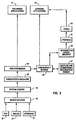
- FIG. 2 there is illustrated a high level diagram of the major software system components of the pen-based system of the preferred embodiment.
- the output signals from pen 29, mouse 27, and keyboard 25 are connected to device drivers 33, which are modules that provide low-level I/O support to their respective devices.
- Device drivers 33 put events into system queues 35. The events in system queues 35 are subsequently processed by a presentation manager 37 which then routes pen and mouse events to pen extensions 39 for processing.
- a typical system includes both pen-aware applications 41 and pen-unaware applications 43.
- Pen-aware applications have the native capacity to recognize and process pen input.
- Pen-unaware applications are those that have the native capacity only to recognize and process keyboard and/or mouse input. Therefore, pen extensions 39 routes pen events directly to pen-aware applications 41.
- pen-unaware applications 43 are not capable of using pen functionality, the system includes a compatibility module 45.
- Compatibility module 45 acts as a pen-aware application on behalf of pen-unaware applications. If, for example, the user inputs handwritten character events to a pen-unaware application, pen extensions 39 routes those events to compatibility module 45, which in turn routes all pen strokes to the gesture and handwriting recognition engine 47. Gesture and handwriting recognition engine 47 processes the pen stroke events and returns a recognition result to the compatibility module 45.
- compatibility module 45 routes it to a recognition event delivery subsystem 49, which accesses profiles 51 set up for the user to determine what actions to perform in a pen-unaware application in response to a particular gesture.
- some tools 53 may be invoked to perform some action on the pen-unaware application 43. If the recognition result returned to compatibility module 45 is recognized as handwriting, the resultant text string is routed directly to the appropriate pen-unaware application 43.
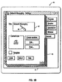
- a computer display screen is designated generally by the numeral 60.
- Screen 60 has displayed thereon a window 61, which in turn displays notebook 63.
- notebook 63 includes various tabs and buttons, and a text entry field 65.
- a pointer is in text field 65 and has assumed the shape of an I-beam 67. The I-beam pointer shape indicates to the user that text field 65 will accept text input from the keyboard.
- Figure 3B which is generally similar to Figure 3A, the system has drawn a pen-shaped pointer 69 in place of I-beam pointer of Figure 3A.
- Pen-shaped pointer 69 indicates to the user that text field 65 will accept handwritten input in the form of characters or gestures.
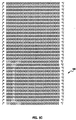
- Icon bitmap 80 is a grid of 32X32 elements, with each element representing one picture element (pel) of VGA resolution.
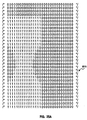
- the I-beam pointer shapes illustrated in Figure 4 include the OS/2 (TM) I-beam pointer 81 and the windows (TM) I-beam pointer 83.
- I-beam pointer shapes illustrated in Figure 4 show the considerable variation in pointers at the pel level while still retaining a shape that users will recognize immediately as I-beams.
- Figure 4 also illustrates that an I-beam pointer may be placed by the designer anywhere in the bitmap.
- FIG 10 there is shown a high level flowchart that depicts a function in pen extensions 39 of Figure 2 that is called for each mouse event received.
- This function is nominally called 60-100 times per second while the mouse or pen is in motion, since these are the standard reporting rates of such devices.
- the pointer shape For each incremental movement of the pointing device, the pointer shape must be redrawn at a new position.
- the operating system or application paints an I-beam pointer to inform the user that keyboard input is permissible.
- the function in Figure 10 will cause the operating system to paint a pen pointer shape 69 of Figure 3B instead if it is determined that the pointer is currently an I-beam.
- the ID of the current pointer is queried and it is tested to see if the current pointer is either the system I-beam, at decision block 1510, or another system pointer, at decision block 1520. If the pointer is the system I-beam, the system changes the pointer shape to the pen at block 1570 and ends at block 1580.
- the system takes no further action and ends at block 1580. Otherwise, the system accesses a pointer table 1400 according to Figure 9 at block 1530 to determine if an entry exists for the current pointer ID.
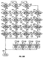
- pointer table 1400 is a table having columns including POINTER ID 1405, PROCESS ID 1410, I-BEAM FLAG 1415.
- pointer table 1400 is constructed to hold up to 250 entries in rows 0-249. As will be explained in detail, pointer table is maintained by adding entries as new pointers are recognized and deleting entries as applications are shut down.
- pointer table 1400 contains an entry for the current pointer at decision block 1540, the system branches to test if the table entry is flagged as an I-beam at decision block 1560. If so, the system paints the pen pointer at block 1570; else the process ends at block 1580. If the test for a pointer table entry at decision block 1540 fails, another routine is called to test the pointer for the I-beam shape, indicated generally by a process block 1550, and shown in detail in Figures 12-18. If the routine indicates the pointer is an I-beam at decision block 1560, the system changes the pointer to a pen at block 1570; else, the routine ends 1580.
- routine that tests for the I-beam shape at block 1550 of Figure 10 is called only once for each application supplied pointer. This is because the routine of Figure 12 makes an entry at blocks 1750 and 1780 in I-BEAM FLAG column 1415 of pointer table 1400 for each pointer flagging whether or not the pointer tested positive for the I-beam shape. Once a pointer table 1400 entry exists for a particular pointer ID, the result of the table entry test at decision block 1540 of Figure 10 is always true and the overhead incurred by the I-beam recognition process is precluded.
- FIG. 11 there is shown the preprocessing that is required at boot time to ready pen extension module 39 (Figure 2) to test and monitor pointer shapes.
- the number of valid entries in pointer table 1400 is zeroed.
- a copy of the Windows (TM) I-beam bitmap is loaded at block 1610, queried at block 1620, and moved into global memory at block 1630 to facilitate the quick testing of Windows I-beam pointers.
- the preferred OS/2 operating system is capable of executing native Windows applications by loading each windows application in its own DOS virtual machine.
- a quirk of this implementation is that each active Windows application is given a unique I-beam pointer ID, even though the applications are all using the same windows-supplied I-beam pointer.
- the bitmap of the standard windows I-beam is kept in memory for fast memory to memory compares with the current pointer.
- the ID of the system supplied I-beam is queried at block 1640. This is the ID used in the test at decision block 1510 of Figure 10.
- Figure 12 charts the high level recognition process.
- the system calls a routine to copy the bitmap of the current pointer into memory where it can be examined and manipulated.
- Figure 13 depicts this processing.
- pen extensions module 39 does not have the same access to bitmaps that the application has since it is running as an extension of the operating system and hence has little knowledge of the application's environment. This requires pen extensions 37 to access the bitmap data in a rather indirect and roundabout manner.
- OS/2 system APIs a presentation space is allocated at block 1800 and the handle of the pointer shape bitmap is queried at block 1810.
- bitmap is set into the presentation space, which is the precursor for reading the bitmap data out of the restricted memory of the graphics engine and into pen extension's global memory at block 1830.
- bitmap data Once the bitmap data has been obtained, it is deleted from the presentation space at block 1840 and the presentation space resource is deallocated at block 1850.
- the system performs an optimized memory to memory compare at block 1710 to see if the pointer is the Windows I-beam. If the compare tests equal at 1720, an entry is added to pointer table 1400 at block 1780, the entry is flagged as an I-beam at block 1785, and the number of valid pointer table entries is incremented at 1790. The number of valid pointer entries is carefully maintained because pointer table 1400 is constructed to have 250 entries and to reduce the search time expended at block 1530, the search is suspended after the last valid entry is found.
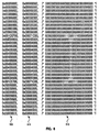
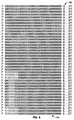
- Bitmap array 510 for an arbitrary I-beam pointer shape.
- Bitmap array 510 is a 32X32 array of binary data, in which the pels of the I-beam shape are designated by ones. It will be noted that the I-beam of bitmap array 510 comprises 28 pels occupying nine columns and fourteen rows. It will further be noted that the I-beam is positioned at an arbitrary location within bitmap array 510.
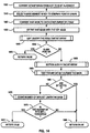
- Figure 14 illustrates the flow for the test of an approximate I-beam shape, for example the I-beam shape of Figure 5A.
- the bitmap array is converted from 8-bit to 32-bit alignment at block 1900.
- the penalty incurred by reformatting the data is more than amply compensated for by the use of CPU instructions that operate on 32-bits at a time.
- Figure 6 illustrates the conversion from 8-bit 600 to 32-bit 610 alignment of bit array 510.
- a pointer shape mask is selected according to the type of pointer being tested and the display resolution.
- a mask 710 for VGA resolution and a mask 810 for XGA resolution are illustrated in Figures 7 and 8, respectively.
- the AND mask of the bitmap is converted to one's complement of itself in preparation for combining the AND and OR masks at block 1930. Because the shape of the pointer may be encoded into either the AND or the OR mask or both, the two masks are combined to ensure that the entire pointer shape is taken into account. And because the AND mask is normally all ones and changes to zeroes to encode the pointer shape, it is inverted at block 1920 to match the formatting of the OR mask, which is the opposite.
- bitmap has been reduced from two masks to one and in order to test the pointer shape against the mask, the pointer shape must be further isolated.
- subroutines are called to justify the pointer shape to the left, at block 1940, and then to the bottom, at block 1950, of the bitmap array.
- decision block 1945 tests at decision block 1945 to see if the pointer is blank, which is not an uncommon occurrence. If so, processing stops and the routine passes back a negative result at block 1955.
- the left and bottom justification processes result, respectively, in bitmap array 520 of Figure 5B and bitmap array 530 of Figure 5C.
- Another subroutine is called to determine if any bit outside the mask is set to one at block 1960. If even a single bit is set to one outside the mask, the test fails at decision block 1965 and false is returned to the calling routine at block 1985. If no bits are set to one outside the mask at decision block 1965, yet another subroutine is called at block 1975 to count the number of bits set under the shape mask. If a sufficient number of bits are set to one at decision block 1975, the pointer shape is considered to be approximately an I-beam and true is returned at block 1980.
- the threshold used to determine if the shape is an I-beam is empirically set and the algorithm currently expects counts of 17 bits set to one for VGA resolution and 24 bits set to one for XGA.
- the number of scan lines is loaded from the bitmap header. Then, the subroutine enters a loop of blocks 2010-2050 where the leftmost bit of each scan line is tested for a one at block 2010. After testing each scan line, a test is made to see if the leftmost bits were all zeroes at decision block 2020. If so, then the start of the pointer image has not yet been located, so each scan line is shifted one bit to the left at block 2030 and the shift count is incremented 2040. A test is conducted to see if the number of shifted bits is greater than or equal to the number of scan columns at decision block 2050. This test catches the case of a blank pointer shape and prevents an infinite loop.
- the subroutine simply returns true at block 2060.
- the shifting of the image to the left at block 2030 continues until finally the leftmost bit of one of the scan lines contains a one at decision block 2020. When this occurs, this image is fully left justified and the subroutine returns false at block 2070.
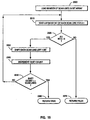
- Figure 16 illustrates the flow of the next step of the recognition algorithm wherein the left justified image is bottom justified.
- the scan line pointer is set to the bottom of the bitmap array at block 2100 so that testing commences at the last or bottom scan line.
- a loop is entered at blocks 2100-2130 in which each scan line is tested in its entirety for a non-zero bit at decision block 2110. If no non-zero bits are found, the scan line pointer is decremented at block 2120. If the scan line pointer points to the top scan line of the bitmap at decision block 2130, the routine returns at block 2140. Else, the loop iterates until a non-zero scan line is found signifying the bottom of the pointer image has been located at which point the'loop exits and goes to the second half of the subroutine.
- a source pointer is initialized at block 2150 to point to the scan line at the bottom of the image and the target pointer is set to point to the bottom of the bitmap array at block 2155.
- These pointers are used to execute a memory-to-memory transfer of the bitmap that effectively bottom justifies the image. This is accomplished in the loop bounded by operations 2165 through 2185 inclusive.
- each scan line is transferred at block 2160 and the source and target pointers are decremented each time at blocks 2175 and 2180, respectively.
- a test is made at decision block 2165 to see if the current source pointer is pointing at the top of the bitmap.
- the source pointer wraps around to the bottom of the bitmap at block 2170 so that the entire bitmap gets transferred.
- the target pointer hits the top of the bitmap at decision block 2185, signifying the completion of the transfer and the loop exits and the subroutine returns at block 2190.
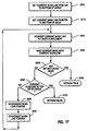
- Figure 17 depicts the logic flow that tests the pointer image for any bit set to one outside the shape mask.
- the scan line pointer is set to the bottom of the array at block 2200, the known start of the pointer image.
- the shape mask pointer is also set to the bottom on the mask at block 2210 to keep in locked step with the bitmap scan line.
- the loop from blocks 2220-2290 inclusive inverts the mask line by taking its ones complement at block 2220 and employing an AND operation at block 2230, and tests it against its associated bitmap scan line at decision block 2240. Any shape that is approximately an I-beam will not have bits set outside the mask. If a non-zero bit is found, the subroutine returns true 2250 which will indicate a non I-beam shape to the calling routine.
- a test is made to see if the pointer reached the top of the of the bit array, signalling completion of the test at decision block 2260. If not, the scan line pointer and mask line pointer are decremented at blocks 2280 and 2290, respectively, and the loop iterates back to block 2220. If the last scan line is reached 2260 at decision block, no bits were found outside the mask and the subroutine returns false at block 2270.
- Figure 18 is the final worker routine of the recognition algorithm. It has now been established that all the non-zero bits are under the shape mask, which signifies a close fit of the two shapes. The last task is to count the bits set under the mask to see if it qualifies as an I-beam. In actuality, the shape mask is not needed in this step since all the non-zero bits are within the mask.
- Initializing loop variables, the shift count, the scan line count, and the bit count are all cleared at blocks 2300, 2305, and 2310, respectively. Then two predefined constants, the number of non-zero mask lines and the number of non-zero mask columns, are loaded for use within the loop, at blocks 2315 and 2320, respectively.
- the current scan line pointer is set to the bottom of the bitmap array and then code falls into an inner loop 2330-2350 and an outer loop 2355-2370.
- the inner loop 2330-2350 traverses each scan line counting each non-zero bit, while the outer loop 2355-2370 iterates through each scan line.
- the leftmost bit of the current scan line is tested for a one. If it is a one, the bit count is incremented block 2335. In any case, the shift count is always incremented at block 2340 and a test is made at decision block 2345 to see if the number of bits shifted is equal to the number of non-zero columns at decision block 2345. If not, the entire scan line is shifted one bit to the left at block 2350 and the loop iterates back to decision block 2330. If the number of bits shifted equals the number of non-zero mask columns at decision block 2345, the shift count is cleared at block 2355 and the scan line pointer is decremented at block 2360 to examine the next scan line.
- a loop is then entered at decision block 2840 wherein each entry is tested to see if it is valid. If it is valid, the entry is tested at decision block to see if it belongs to the application being shut down. If so, the count of valid entries is decremented at block 2855 and the entry is removed from the table at block 2860. Regardless of the outcome of the test at decision 2850, the loop count is decremented at block 2865 and tested for zero 2870 at block. If not zero, there are still some valid entries in pointer table 1400 so the table-pointer is incremented at block 2875 and the loop iterates back to decision block 2840.
- pointer table 1400 is constructed to contain 250 entries, only a minimum number of entries are examined in most practical cases.
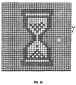
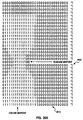
- FIG 24 there is illustrated the bitmap 2410 for the Windows (TM) hour glass pointer.
- the hour glass is a 'thin waisted' shape and in order for a mask to be effective, it too has to have a thin waist.
- the wider the waist of the mask the more rectangular the shape becomes, resulting in a decrease of recognition accuracy.
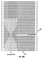
- Figures 26A and 26B a misalignment of the mask with the pointer shape can result in failure to recognize an hour glass pointer shape.
- Figure 26A illustrates a bit array 2610 for a fine shape mask to an hour glass pointer
- Figure 26B illustrates a bit array for an hour glass pointer 2620.
- Hour glass shape 2620 is still recognizable as an hour glass, but it is short and therefore has a low waist, as indicated at scan line midpoint 2630. Therefore, the wide top of hour glass pointer 2620 coincides with the waist, indicated at scan line midpoint 2640, of the mask 2610 which would cause the recognition algorithm to fail due to non-zero bits outside the mask.
- a potential problem with shape masks is that as they get larger, such as the hour glass mask in Figure 26B, the greater the likelihood that some non-hour glass shape will fall under the mask.
- a high bit count threshold on the order of one hundred fifty, might provide effective filtering, it is not necessarily effective in all cases.
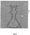
- some other shapes for example the queen pointer shape of bitmap 2810 of Figure 28, would pass both tests. Mistaking the queen pointer for a busy application would cause serious usability problems.
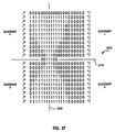
- the second embodiment employs a modified, albeit slightly longer, algorithm that uses a coarse 2510 and a fine mask 2520, shown in Figures 25A and 25B, respectively, and takes pointer image symmetry into account, as shown in Figure 27.
- hour glass pointer image 2710 is symmetrical about both its scan line midpoint 2715 and its column midpoint 2720. Scan line midpoint 2715 and column midpoint 2720 divide pointer image 2710 into four quadrants.
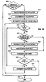
- Figure 19 shows the slightly modified logic of the second embodiment of the present invention.
- the pointer shape has already been left and bottom justified and at block 2400 a test for any non-zero bit outside the coarse mask is made.
- the coarse mask is designed to eliminate a high percentage of non-hour glass pointers while permitting considerable license in the design of the hour glass. If any bit is set outside the course mask at decision block 2410, processing is halted and false is returned at block 2495. If no bits are set at decision block 2410, the pointer shape is centered over the fine mask block 2420.
- Figure 20 demonstrates the flow of the centering technique in order to eliminate the problem of scan line mismatches illustrated in Figures 26A and 26B.
- Two loops are entered in which the system counts the number of non-zero pointer scan lines at block 2500 and the number of non-zero pointer columns at block 2510.
- the resultant non-zero scan line and column counts are divided by 2 to calculate the midpoint of the pointer shape at block 2520.
- the midpoint of the fine shape mask is also calculated by taking those two known constants and dividing by 2 at block 2530. Then to find the difference between the two midpoints of the two comparands, the midpoint X and Y of the pointer shape is subtracted from the midpoint X and Y of the fine mask at block 2540. Note that the calculated X and Y displacements may be zero or a positive number, but may never be negative since the pointer shape cannot be larger than the fine mask.
- the fine mask is left justified an amount equal to the column displacement at block 2550 and bottom justified an amount equal to the scan line displacement at block 2560.
- the net effect of these operations is to superimpose the midpoint of the fine mask over the midpoint of the pointer shape.
- the superimposition of the pointer shape and the fine mask permits the mask to have a smaller and more tightly contoured silhouette, thereby increasing recognition accuracy.
- the routine returns to the caller at block 2570 passing the midpoint of the pointer to be used in the test for symmetry.
- Figure 27 shows the order of the quadrants that share the midpoint of the pointer image as an origin.
- Figure 22A is the subroutine that counts the bits under the fine mask by quadrant.
- the subroutine of Figure 22A is identical to the previously described subroutine of Figure 18 of the first embodiment that counts the bits under the mask, with the exception that a separate bit counter is maintained for each quadrant.
- block 2705 all 4 quadrant bit counters are cleared. Bit counting commences as in Figure 18 by means of an inner and outer loop, however as non-zero bits are detected at decision block 2730, a subroutine is called at block 2732 to increment the quadrant count.
- Figure 22B shows the logic flow of determining in which quadrant a bit is located.
- three tests are made at decision blocks 2771, 2772, and 2773 to see if the column count and the scan line count are odd or even.
- the image In order to test for symmetry, the image must be divided into symmetrical halves and if there are an odd number of columns or scan lines, the center column or scan line must be ignored since it is the axis of symmetry. In the case of an even number of columns or scan lines, the actual line of symmetry falls between the two columns or rows and the computed midpoint column and row become part of quadrants 3 and 4, or 3 and 2, respectively.
- operations 2701-2704, 2706-2709, 2716-2719 and 2721-2724 act as sieves to determine in which quadrant the newly found bit falls.
- bits found on the axis of symmetry are not counted and logic simply returns at block 2763.
- Operations 2751-2754 increment the appropriate quadrant count and the subroutine returns at block 2763.
- the testing of the bit count at decision block 2560 uses a threshold appropriate for the hour glass shape, empirically set at one hundred fifty bits. If the test fails, a negative result is returned at block 2495. Else, the pointer image is checked for symmetry at block 2470.
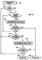
- Figure 21 charts the logic flow of the symmetry checking subroutine.
- the fine shape mask for the hour glass of Figure 25B is queried to determine if any symmetry checks are required for this particular pointer shape. If no checks are required at decision block 2610, the system simply returns to the caller a positive indication for symmetry at block 2680.
- both column and scan line symmetry are required so the operation at decision block 2620 tests true and the logic falls through to block 2630 where the quadrant bit counts on each side the column symmetry line are added together. These two counts are compared and if they differ by more than three pels at decision block 2640, the two sides are considered asymmetrical and the subroutine returns a negative indication at block 2690.
- This modification incurs a slight performance penalty from having to process a second mask, superimposing the two images and checking symmetry, however the penalty is mitigated by the increased reliability of the recognition algorithm. The penalty is further mitigated by having the symmetry check be conditional by pointer type.
- the approach described herein is well adapted to accomplish the recognition of pointer shapes.
- the text pointer shape must approximate a shape of an I-beam
- the bitmap of the pointer is examined for the purpose determining if the pointer shape has the visual appearance of an I-beam.
- the pointer shape is tested against a mask of an I-beam that permits a good amount of variation in I-beam size, shape and features while rejecting any shape that is not a reasonable facsimile of an I-beam.
- the preferred embodiment takes into consideration many variables. For example, multiple display resolutions, e.g., VGA, SVGA and XGA resolution display drivers, may each have different pointer bitmap sizes (e.g. 32 x 32, 40 x 40). The difference in pointer resolution is made transparent to the recognition algorithm by selecting a shape mask based on pointer size. The preferred embodiment is also unaffected by the use of color in a mouse pointer, since variation in color is ignored and the pointer is treated as if it were monochrome.
- multiple display resolutions e.g., VGA, SVGA and XGA resolution display drivers, may each have different pointer bitmap sizes (e.g. 32 x 32, 40 x 40).
- the difference in pointer resolution is made transparent to the recognition algorithm by selecting a shape mask based on pointer size.
- the preferred embodiment is also unaffected by the use of color in a mouse pointer, since variation in color is ignored and the pointer is treated as if it were monochrome.
- a pointer shape is not a standard bitmap.
- a pointer bitmap actually consists of two masks, the XOR and the AND mask, along with an array of color index values that combine to produce a pointer shape image that is transparent except for the desired pointer shape.
- the pointer shape may be coded into either the XOR or AND mask or both.
- the XOR mask is normally zeroes and the shape is encoded by converting zero bits to one bits.
- the AND mask is normally all ones and gets converted to zeroes to encode the shape.
- the 32 x 32 pel pointer shape contains 1024 pels of which 18 or so may be used to define the shape.
- the designer of the pointer is free to encode the pointer anywhere within the boundary of the bitmap.
- the preferred embodiment locates the pointer image within the bitmap and then relocates the image to the bottom left of the bitmap.
- the preferred embodiment allows considerable license for creative I-beam shapes while rejecting non-I-beam shapes with high certainty.
- some pointer shapes may require extra operations in the recognition process where the pointer shape being tested must be precisely aligned with a higher resolution mask.
- the system may search for such symmetries in the pointer shape under test.
- Bitmaps are built to accommodate fast transfers at the device driver level. Therefore the top-leftmost bit ends up as the bottom-leftmost bit in the binary format.
- bitmaps are byte arrays which means that two bits that are contiguous in the image may be separated by 15 bits if they cross a byte boundary. All of this requires significant bit manipulation of the bitmap prior to processing. Two consecutive bits can become discontiguous when treating the bitmap data as 32-bit data instead of 8-bit data. Therefore, the preferred embodiment reformats the bitmap data from 8-bit to 32-bit alignment.
- Pen-based systems have very stringent performance requirements that do not allow computationally intensive operations such as optical recognition on a mouse-move or pen-down event basis for all application defined pointers.
- the process of classifying application defined pointers as text or non-text pointer shapes is optimized to the point of having no discernible effect on system responsiveness or performance.
- the preferred embodiment uses optical recognition of the I-beam pointer shape to distinguish text window areas from non-text window areas, this approach may also be used in any task where the operating system would benefit from knowing, as does the user, the specific state of an application as a pointing device traverses the application.
- recognition of an hour-glass or clock can be used to determine when an application is currently busy and unable to process user input.
Description
- The present invention broadly relates to computers and data processing systems, and in particular to the handling of screen pointers in such systems.
- Pen software extensions to operating systems, such as the preferred IBM OS/2 operating system, permit users to write directly into a window characters that are subsequently sent to a gesture and handwriting recognition engine for recognition. By default, the system treats the hand printed shapes as gestures unless the window is one which accepts text such as an edit field or a text entry window. Pen-based systems are described generally in U. S. Patent 5,252,951 by Alan Tannenbaum, et al. entitled "Graphical User Interface with Gesture Recognition in a Multi-Application Environment".
- By convention, fields that accept text indicate so by displaying an I-beam mouse pointer when the pointer is positioned over the text field. The operating system provides a standard I-beam mouse pointer for applications to use so that, 1) all entry fields have a uniform look and, 2) the developer of each application does not have to design and ship a custom version of an I-beam mouse pointer with its respective product.
- The pen-based system software takes advantage of this standard I-beam to know the user is writing into a text field. As the user moves the stylus close to the surface and begins to write, the system moves the mouse pointer to the location of the stylus. If the mouse pointer is in a text field, the pointer becomes an I-beam. The pen-based system is unaware of the pointer shape but compares the ID of the pointer to the ID of the system supplied I-beam pointer. If the IDs match, the system takes two actions. First, the system changes the mouse pointer from an I-beam to a pen figure to alert the user that he or she may write directly into the field with the stylus. Second, the system treats the handwritten characters primarily as text rather than gestures. The examination of application, window, and pointer characteristics for the purpose interpreting pen or stylus input is discussed in IBM Technical Disclosure Bulletin, Vol. 38, No. 09, September 1995, entitled, "Data Interpretation Techniques for a Pen-based Computer".
- The problem this faces however is that many application developers ship their applications with their own version of an I-beam pointer.
- These developers design their own I-beam pointer shapes for aesthetic reasons or simply to distinguish their applications from those of the competition. In all cases, though, these custom I-beams still retain some resemblance to the standard I-beam shape to ensure good human factors. Otherwise, users might become confused and not perceive that the fields accept text input. Most of the dominant word processor applications are shipped with their own I-beam pointers rendering the presently existing pen-based systems techniques of comparing the pointer IDs somewhat ineffective.
- Another problem in pen-based systems is ascertaining when an application is unable to process mouse and keyboard input. An application normally signals this 'busy' condition by displaying an hour glass pointer. This is usually sufficient indication and the user ceases input until the hour glass pointer gets restored to the arrow pointer. In many cases however, while the application is in a busy state, there is already mouse or keyboard input in the system queue that has been directed to other active applications on the desktop. But given the design of both the OS/2 and Windows operating systems, the enqueued input cannot be dequeued and dispatched to the target application until the busy application has first, in effect, told the operating system it has finished dequeueing mouse and keyboard input. The operating system has no way of knowing the application is momentarily in a busy state, although the user does. If the operating system had way of detecting this busy state, it could summarily examine the input queue and dequeue/route any mouse or keyboard input that was directed at a non-busy application that was waiting on user input. The result would be the removal of a processing bottleneck.
-
EP 0 533 607, discloses a method and system of providing multiple selections in text on a computer display. Multiple selections of text are provided while allowing swipe and type editing operations. A normal typing cursor is displayed to indicate where newly input text will be inserted. When the text has been selected, it is so designated by selected emphasis. The cursor is changed from the normal cursor to the second cursor. The second cursor has a shape that is different than the normal cursor and indicates that subsequent typing will activate the swipe and type operation on the selected text. -
EP 0 678 805, discloses a method and system for multiple display pointers for computers with graphical user interfaces. A pointer system provides multiple display pointers that can be created and identified by a computer user such that each pointer is associated with a particular application. A user can recall respective pointers and pointer locations by selecting a pointer identifier. - In accordance with the present invention there is now provided a method of operating a pen-based computer system to determine that the location of a current pointer is capable of accepting character data, said current pointer having a current pointer ID and the system having a system I-beam pointer with associated system I-beam pointer ID, said method comprising the steps of: determining whether said current pointer ID equals said system I-beam pointer ID; whenever said current pointer ID does not equal said system I-beam pointer ID, determining whether said pointer ID is in a table of pointer IDs and flagged in said table as being an I-beam pointer; and whenever said current pointer ID is not in said table of pointer IDs, determining whether said pointer has an I-beam shape; in response to said pointer ID equalling said system I-beam pointer ID or if said pointer ID is in a table of pointer ID's and flagged (1785)in said table as being an I-beam pointer or whenever said pointer has an I-beam shape, changing said pointer to a pen-shaped pointer (1570) to indicate computer system acceptance of text input.
- Preferably the method further comprises the steps of whenever said pointer ID equals said system I-beam pointer ID, and/or whenever said pointer ID is in said table of pointer IDs and flagged in said table as being an I-beam pointer, changing said pointer to a pen-shaped pointer.
- Preferably the method provides a method of determining whether a non-system pointer is equivalent to a system pointer, said non-system pointer having a pointer ID, said method comprising the steps of:
- determining whether said pointer ID is in a table of pointer IDS and flagged in said table as being equivalent to said system pointer; and, whenever said pointer ID is not in said table of pointer IDs, determining, based on the shape of said non-system pointer, whether said non-system pointer is equivalent to said system pointer.
-
- In a preferred embodiment, whenever said non-system pointer is determined, based on shape, to be equivalent to said system pointer, said pointer ID is added to said table of pointer IDS and said pointer ID is flagged as being equivalent to said system pointer. Preferably said step of determining, based on shape, whether said non-system pointer is equivalent to said system pointer comprises the step of comparing said non-system pointer to a predefined mask. In some circumstances, said non-system pointer may be compared first to a predefined coarse mask; and whenever all picture elements of said non-system pointer lie within said coarse mask, the non-system pointer is compared to a predefined fine mask. Whenever all picture elements of said non-system pointer lie within said mask (or said fine mask), it is preferred that said method further comprises the steps of counting the number of picture elements comprising said non-system pointer, and whenever the counted number of picture elements comprising said non-system pointer is greater than a predetermined threshold, determining whether said non-system pointer satisfies a predetermined symmetry condition.
- Viewed form another aspect the present invention provides for a pen-based computer system having a display with system I-beam pointer displayable on said display, said system I-beam pointer having a system I-beam pointer ID, and having a system for determining that a location on said display indicated by a pointer having a pointer ID is capable of accepting character data comprising:
- means for determining whether said pointer ID equals said system I-beam pointer ID;
- means for determining, whenever said pointer ID does not equal said system I-beam pointer ID, whether said pointer ID is in a table of pointer IDs and flagged in said table as being an I-beam pointer; and,
- means for determining, whenever said pointer ID is not in said table pointer IDs, whether said pointer has an I-beam shape.
-
- Preferably the system provides a computer system having a display and a system for determining that a non-system pointer having a pointer ID is equivalent to a system pointer comprising:
- means for determining whether said pointer ID is in a table of pointer IDs and flagged in said table as being equivalent to said system pointer; and,
- means for determining, whenever said pointer ID is not in said table pointer IDs, based on the shape of said non-system pointer, whether said non-system pointer is equivalent to said system pointer.
-
- Viewed from another aspect, in a pen-based computer system having a system I-beam pointer having a system I-beam pointer ID, there is provided a method of determining that a location of a pointer is capable of accepting character data, said pointer having a pointer ID, said method comprising the computer implemented steps of:
- determining whether said pointer ID equals said system I-beam pointer ID;
- whenever said pointer ID does not equal said system I-beam pointer ID, determining whether said pointer ID is in a table of pointer IDs and flagged in said table as being an I-beam pointer; and,
- whenever said pointer ID is not in said table of pointer IDs, determining whether said pointer has an I-beam shape.
-
- Preferably the method further comprises the steps of adding said pointer ID to said table of pointer IDs, flagging said pointer ID as being an I-beam pointer, and changing said pointer to a pen-shaped pointer, whenever said pointer is determined to have an I-beam shape.
- In the preferred embodiment, said step of determining whether said pointer has an I-beam shape includes the steps of comparing said pointer to a predefined I-beam pointer-shaped mask; and whenever all picture elements of said pointer lie within said I-beam pointer-shaped mask, counting the number of picture elements comprising said pointer; and whenever the number of picture elements comprising said pointer is greater than a predetermined threshold, changing said pointer to a pen-shaped pointer.
- Thus mouse pointers displayed by various computer program applications may be recognised according to their visual appearance to determine the dynamic state or environment of the applications. Accurate pointer shape recognition ensures that non-target pointer shapes are rejected with a high degree of confidence. The pointer shape recognition is performed in a computationally efficient manner so that the overhead added by the recognition process has no discernible effect on the responsiveness or performance of the computer, and the process can be performed on computers with varying display resolutions and color capabilities.
- In one preferred embodiment, the system determines whether or not a non-system pointer is equivalent to a system pointer. The system and the non-system pointer each have pointer ID. The system first determines whether the pointer ID of the non-system pointer is in a table of pointer IDs and flagged in the table as being equivalent to the system pointer. Whenever the pointer ID of the non-system pointer is not in the table of pointer IDs, the system determines, based on the shape of the non-system pointer, whether the non-system pointer is equivalent to the system pointer.
- Further in this embodiment, the system determines, based on shape, whether the non-system pointer is equivalent to the system pointer by comparing the non-system pointer to a predefined mask. Whenever all picture elements of the non-system pointer lie within the mask, the system determines whether the number of picture elements comprising the non-system pointer is greater than a predetermined threshold. Whenever the system determines the non-system pointer to be equivalent to the system pointer, the system adds the pointer ID of the non-system pointer to the table of pointer IDs and flags the pointer ID as being equivalent to the system pointer.
- In another preferred embodiment, the system may determine whether the non-system pointer is equivalent to the system pointer by first comparing the non-system pointer with a predefined coarse mask. If all picture elements of the non-system pointer lie within the coarse mask, the system then compares the non-system pointer with a predefined fine mask. Whenever all picture elements of said non-system pointer lie within the fine mask, the system determines whether the number of picture elements comprising the non-system pointer exceeds a predetermined threshold. The system may then determine whether the non-system pointer satisfies a predetermined symmetry condition.
- The above has particular utility in a multitasking pen-based computer system in which a single task is dedicated to routing user input such as keyboard, mouse or stylus events to various computer programs executing concurrently under user control.
- Preferably the present invention provides a method for assessing pointer shape in a computer system comprising the steps of: providing a predetermined pointer mask shape; and comparing the current pointer shape with the predefined pointer mask shape to determine whether or not the current pointer shape corresponds to said predetermined pointer mask shape.
- In a preferred embodiment, said step of comparing comprises the steps of verifying that all non-zero picture elements of said current pointer shape lie within said predetermined pointer mask shape; verifying that the number of non-zero picture elements of said current pointer shape exceeds a predetermined threshhold; and verifying that said current pointer shape satisfies one or more predetermined symmetry conditions, for said current pointer shape to correspond to said predetermined pointer mask shape. Clearly the exact form of testing to be used in the comparison shape can be adapted to user requirements; in some circumstances for example, it may be acceptable for a small proportion of picture elements of the current pointer shape to lie outside the predetermined pointer mask shape. The actual form of testing is likely to depend on the particular shape to be tested against.
- Also in the preferred embodiment, said predetermined pointer mask shape and said current pointer shape are stored as bit maps, and the method further comprises the steps of converting the bit map of the current pointer shape from 8-bit to 32-bit alignment prior to said comparing step, and the initial steps of left-justifying and bottom-justifying the non-zero picture elements of the current pointer shape. This makes the subsequent comparison easier.
- In the preferred embodiment, the method also comprises the steps of maintaining a table of ID's of possible pointer shapes, the entry for each shape including a flag indicating whether or not that shape corresponds to said predetermined pointer mask shape; and responsive to said comparing step, adding an entry for the current pointer shape to said table, and setting the corresponding flag accordingly. The pointer shape is then assessed by the steps of: initially determining whether there is an entry for the ID of the current pointer shape; and responsive to locating such entry, investigating the flag for that entry to determine whether or not the current pointer shape corresponds to said predetermined pointer mask shape; and responsive to not locating such entry, performing said comparing step. Thus the table allows the system to remember whether a pointer shape has previously been investigated, to save having to repeatedly process the same pointer shape.
- Said predetermined pointer mask shape may correspond to an hour glass (indicating "busy"). In this case, the computer system typically supports at least first and second applications and has an input queue which stores input data for said first and second applications, and said first application assigns an hour glass shape to the current pointer shape if input data for said first application is at the head of the queue, but said first application is currently too busy to process this input data, and said computer system is responsive to a determination that the current pointer shape corresponds to said hour glass shape to dequeue any data for said second application from the remainder of the queue. This approach can help to prevent a busy first application from blocking a second application.
- Said predetermined pointer mask shape may also correspond to an I-beam shape, which is typically used to indicate that text input is available. In a pen-based computer system it is preferred that responsive to a determination that the current pointer shape corresponds to an I-beam shape, said computer system changes the current pointer shape to one that indicates that text may currently be input using the pen.
- It will be appreciated of course that a single computer system may store multiple predefined mask shapes, such as both an hour glass and an I-beam, and test the current pointer shape against each such predefined mask shape.
- Preferred embodiments of the invention will now be described in detail by way of example only with reference to the following drawings:
- Figure 1 is a hardware block diagram of the preferred embodiment;
- Figure 2 is an architectural diagram of the major software components of the preferred embodiment;
- Figures 3A and 3B are pictorial representations of an editable text window displaying an I-beam and a pen pointer shape, respectively;
- Figure 4 is a pictorial representation illustrating various I-beam pointers;
- Figures 5A, 5B and 5C illustrate an I-beam pointer as found in the pointer image (5A), the image left-justified (5B) and the image bottom-left-justified (5C);
- Figure 6 illustrates a bitmap formatted as both 8-bit and 32-bit data;
- Figure 7 illustrates I-beam pointer shape masks for VGA display resolution;
- Figure 8 illustrates I-beam pointer shape masks for XGA display resolution;
- Figure 9 is a diagram of a pointer table according to the preferred embodiment;
- Figures 10-18 are flow diagrams of a software implementation of the I-beam pointer shape recognition method in the preferred embodiment;
- Figures 19-22 are flow diagrams of a software implementation of an alternative embodiment in which hour glass pointer shape recognition is performed in order to determine when applications are in a busy or unavailable state;
- Figure 23 is a flow diagram of pointer entries being removed from the pointer table whenever an application is shut down;
- Figure 24 is a pictorial representation of the Windows (TM) hour glass 'application busy' pointer shape;
- Figures 25A and 25B are representations of the coarse and fine mask for the hour glass pointer shape;
- Figure 26 illustrates misalignment of the hour glass pointer image and the fine mask;
- Figure 27 illustrates the symmetry lines and quadrants of the hour glass pointer shape; and
- Figure 28 illustrates the queen pointer shape in the Chess program application.
-
- Referring now to the drawings, and first Figure 1, a hardware block diagram of a personal computer system with which the system and method of the present invention may be implemented is designated generally by the numeral 10.
System 10 includesprocessor 11, which includes a central processing unit (CPU) 13 andrandom access memory 15.System 10 preferably also includes additional memory in the form of a harddisk storage device 17 and afloppy disk device 19.Floppy disk device 19 is adapted to receive adiskette 21 on which may be recorded software for programs.System 10 also includes user interface hardware devices including adisplay 23, akeyboard 25, amouse 27, and a pen orstylus 29.System 10 preferably includes aprinter 31. - Referring now to Figure 2, there is illustrated a high level diagram of the major software system components of the pen-based system of the preferred embodiment. At the bottom of Figure 2, the output signals from
pen 29,mouse 27, andkeyboard 25 are connected todevice drivers 33, which are modules that provide low-level I/O support to their respective devices.Device drivers 33 put events intosystem queues 35. The events insystem queues 35 are subsequently processed by apresentation manager 37 which then routes pen and mouse events to penextensions 39 for processing. - A typical system includes both pen-
aware applications 41 and pen-unaware applications 43. Pen-aware applications have the native capacity to recognize and process pen input. Pen-unaware applications are those that have the native capacity only to recognize and process keyboard and/or mouse input. Therefore,pen extensions 39 routes pen events directly to pen-aware applications 41. However, since pen-unaware applications 43 are not capable of using pen functionality, the system includes acompatibility module 45. -
Compatibility module 45 acts as a pen-aware application on behalf of pen-unaware applications. If, for example, the user inputs handwritten character events to a pen-unaware application,pen extensions 39 routes those events tocompatibility module 45, which in turn routes all pen strokes to the gesture andhandwriting recognition engine 47. Gesture andhandwriting recognition engine 47 processes the pen stroke events and returns a recognition result to thecompatibility module 45. - If the recognition event is a gesture,
compatibility module 45 routes it to a recognitionevent delivery subsystem 49, which accessesprofiles 51 set up for the user to determine what actions to perform in a pen-unaware application in response to a particular gesture. Optionally, sometools 53 may be invoked to perform some action on the pen-unaware application 43. If the recognition result returned tocompatibility module 45 is recognized as handwriting, the resultant text string is routed directly to the appropriate pen-unaware application 43. - Referring now to Figure 3A, a computer display screen is designated generally by the numeral 60.
Screen 60 has displayed thereon awindow 61, which inturn displays notebook 63. In a manner familiar to those skilled in the art,notebook 63 includes various tabs and buttons, and atext entry field 65. In a pen-based system, whenever the user brings the pen or stylus (not shown) nearscreen 60, the system moves the pointer to the location of the pen and processes actions with the pen according to the characteristics of the pen location. In Figure 3A, a pointer is intext field 65 and has assumed the shape of an I-beam 67. The I-beam pointer shape indicates to the user that textfield 65 will accept text input from the keyboard. - In Figure 3B, which is generally similar to Figure 3A, the system has drawn a pen-shaped
pointer 69 in place of I-beam pointer of Figure 3A. Pen-shapedpointer 69 indicates to the user that textfield 65 will accept handwritten input in the form of characters or gestures. - Referring now to Figure 4, there is shown a pictorial representation of an
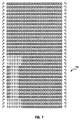
icon bitmap 80, such as would be displayed in an icon editor application, with six representative I-beam pointer shapes drawn therein.Icon bitmap 80 is a grid of 32X32 elements, with each element representing one picture element (pel) of VGA resolution. The I-beam pointer shapes illustrated in Figure 4 include the OS/2 (TM) I-beam pointer 81 and the windows (TM) I-beam pointer 83. - The I-beam pointer shapes illustrated in Figure 4 show the considerable variation in pointers at the pel level while still retaining a shape that users will recognize immediately as I-beams. Figure 4 also illustrates that an I-beam pointer may be placed by the designer anywhere in the bitmap.
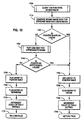
- Referring now to Figure 10, there is shown a high level flowchart that depicts a function in
pen extensions 39 of Figure 2 that is called for each mouse event received. This function is nominally called 60-100 times per second while the mouse or pen is in motion, since these are the standard reporting rates of such devices. For each incremental movement of the pointing device, the pointer shape must be redrawn at a new position. When the pointing device is over an entry field of any type, the operating system or application paints an I-beam pointer to inform the user that keyboard input is permissible. The function in Figure 10 will cause the operating system to paint apen pointer shape 69 of Figure 3B instead if it is determined that the pointer is currently an I-beam. - Starting at
block 1500, the ID of the current pointer is queried and it is tested to see if the current pointer is either the system I-beam, atdecision block 1510, or another system pointer, atdecision block 1520. If the pointer is the system I-beam, the system changes the pointer shape to the pen atblock 1570 and ends atblock 1580. - If the pointer is one of the other pointers supplied by the operating system, the system takes no further action and ends at
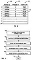
block 1580. Otherwise, the system accesses a pointer table 1400 according to Figure 9 atblock 1530 to determine if an entry exists for the current pointer ID. - Turning to Figure 9, pointer table 1400 is a table having columns including
POINTER ID 1405,PROCESS ID 1410, I-BEAM FLAG 1415. In the preferred embodiment, pointer table 1400 is constructed to hold up to 250 entries in rows 0-249. As will be explained in detail, pointer table is maintained by adding entries as new pointers are recognized and deleting entries as applications are shut down. - Returning to Figure 10, if pointer table 1400 contains an entry for the current pointer at
decision block 1540, the system branches to test if the table entry is flagged as an I-beam atdecision block 1560. If so, the system paints the pen pointer atblock 1570; else the process ends atblock 1580. If the test for a pointer table entry atdecision block 1540 fails, another routine is called to test the pointer for the I-beam shape, indicated generally by aprocess block 1550, and shown in detail in Figures 12-18. If the routine indicates the pointer is an I-beam atdecision block 1560, the system changes the pointer to a pen atblock 1570; else, the routine ends 1580. - Referring to Figure 12, it will be noted that the routine that tests for the I-beam shape at
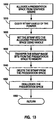
block 1550 of Figure 10 is called only once for each application supplied pointer. This is because the routine of Figure 12 makes an entry atblocks BEAM FLAG column 1415 of pointer table 1400 for each pointer flagging whether or not the pointer tested positive for the I-beam shape. Once a pointer table 1400 entry exists for a particular pointer ID, the result of the table entry test atdecision block 1540 of Figure 10 is always true and the overhead incurred by the I-beam recognition process is precluded. The fact that a large majority of applications use the system supplied I-beam and other system pointers and that the non-system pointers are tested only once keeps the processing requirements of this function to a minimum. The additional load on the system is not discernible by even a sophisticated and knowledgeable user. - Referring now to Figure 11, there is shown the preprocessing that is required at boot time to ready pen extension module 39 (Figure 2) to test and monitor pointer shapes. At
block 1600 the number of valid entries in pointer table 1400 is zeroed. In the preferred embodiment, a copy of the Windows (TM) I-beam bitmap is loaded atblock 1610, queried atblock 1620, and moved into global memory atblock 1630 to facilitate the quick testing of Windows I-beam pointers. - The preferred OS/2 operating system is capable of executing native Windows applications by loading each windows application in its own DOS virtual machine. A quirk of this implementation is that each active Windows application is given a unique I-beam pointer ID, even though the applications are all using the same windows-supplied I-beam pointer. To speed up the recognition process, the bitmap of the standard windows I-beam is kept in memory for fast memory to memory compares with the current pointer.
- In the last step of initialization, the ID of the system supplied I-beam is queried at
block 1640. This is the ID used in the test atdecision block 1510 of Figure 10. - Figure 12 charts the high level recognition process. As indicated generally at
block 1700, the system calls a routine to copy the bitmap of the current pointer into memory where it can be examined and manipulated. Figure 13 depicts this processing. It should be noted thatpen extensions module 39 does not have the same access to bitmaps that the application has since it is running as an extension of the operating system and hence has little knowledge of the application's environment. This requirespen extensions 37 to access the bitmap data in a rather indirect and roundabout manner. Using well known OS/2 system APIs, a presentation space is allocated atblock 1800 and the handle of the pointer shape bitmap is queried atblock 1810. Then the bitmap is set into the presentation space, which is the precursor for reading the bitmap data out of the restricted memory of the graphics engine and into pen extension's global memory atblock 1830. Once the bitmap data has been obtained, it is deleted from the presentation space atblock 1840 and the presentation space resource is deallocated atblock 1850. - Returning to Figure 12, after querying the bitmap data at
block 1700, the system performs an optimized memory to memory compare atblock 1710 to see if the pointer is the Windows I-beam. If the compare tests equal at 1720, an entry is added to pointer table 1400 atblock 1780, the entry is flagged as an I-beam atblock 1785, and the number of valid pointer table entries is incremented at 1790. The number of valid pointer entries is carefully maintained because pointer table 1400 is constructed to have 250 entries and to reduce the search time expended atblock 1530, the search is suspended after the last valid entry is found. - If the compare at
decision block 1720 tests false, another routine is called atblock 1730 to conduct further tests on the pointer. If this routine reports a negative result atdecision block 1740, an entry is added to the pointer table atblock 1750, the entry is flagged as a non I-beam atblock 1760, the number of valid pointer table entries is incremented atblock 1770 and the routine returns the negative result to the calling routine atblock 1775. If the compare atdecision block 1740 tests true, an entry is added to the pointer table atblock 1780, the entry is flagged as an I-beam atblock 1785, the number of valid pointer table entries is incremented at 1790, and the result is returned atblock 1795. - Referring to Figure 5A, there is shown a
bitmap array 510 for an arbitrary I-beam pointer shape.Bitmap array 510 is a 32X32 array of binary data, in which the pels of the I-beam shape are designated by ones. It will be noted that the I-beam ofbitmap array 510 comprises 28 pels occupying nine columns and fourteen rows. It will further be noted that the I-beam is positioned at an arbitrary location withinbitmap array 510. - Figure 14 illustrates the flow for the test of an approximate I-beam shape, for example the I-beam shape of Figure 5A. To streamline processing through this routine and its ancillary subroutines, shown in Figures 15-18, the bitmap array is converted from 8-bit to 32-bit alignment at
block 1900. The penalty incurred by reformatting the data is more than amply compensated for by the use of CPU instructions that operate on 32-bits at a time. Figure 6 illustrates the conversion from 8-bit 600 to 32-bit 610 alignment ofbit array 510. Atblock 1910, a pointer shape mask is selected according to the type of pointer being tested and the display resolution. Amask 710 for VGA resolution and amask 810 for XGA resolution are illustrated in Figures 7 and 8, respectively. Utilizing different masks increases the accuracy of pointer shape recognition. Atblock 1920, the AND mask of the bitmap is converted to one's complement of itself in preparation for combining the AND and OR masks atblock 1930. Because the shape of the pointer may be encoded into either the AND or the OR mask or both, the two masks are combined to ensure that the entire pointer shape is taken into account. And because the AND mask is normally all ones and changes to zeroes to encode the pointer shape, it is inverted atblock 1920 to match the formatting of the OR mask, which is the opposite. - At this point, the bitmap has been reduced from two masks to one and in order to test the pointer shape against the mask, the pointer shape must be further isolated. To accomplish this, subroutines are called to justify the pointer shape to the left, at
block 1940, and then to the bottom, atblock 1950, of the bitmap array. Before bottom justifying the image though, the system tests atdecision block 1945 to see if the pointer is blank, which is not an uncommon occurrence. If so, processing stops and the routine passes back a negative result atblock 1955. The left and bottom justification processes result, respectively, inbitmap array 520 of Figure 5B andbitmap array 530 of Figure 5C. - Now that the image of the pointer is in a known place, another subroutine is called to determine if any bit outside the mask is set to one at
block 1960. If even a single bit is set to one outside the mask, the test fails atdecision block 1965 and false is returned to the calling routine atblock 1985. If no bits are set to one outside the mask atdecision block 1965, yet another subroutine is called atblock 1975 to count the number of bits set under the shape mask. If a sufficient number of bits are set to one atdecision block 1975, the pointer shape is considered to be approximately an I-beam and true is returned atblock 1980. The threshold used to determine if the shape is an I-beam is empirically set and the algorithm currently expects counts of 17 bits set to one for VGA resolution and 24 bits set to one for XGA. - The four subroutines invoked generally at
blocks column 820 ofbitmap array 810 of Figure 8, and if the algorithm used right justification, it would first have to shift the image past the padding of zeroes. This would be time consuming. When dealing with bitmaps of resolution greater than 32x32, the pointer image will usually be closer to the left edge of the bitmap. - In Figure 15, at
block 2000, the number of scan lines is loaded from the bitmap header. Then, the subroutine enters a loop of blocks 2010-2050 where the leftmost bit of each scan line is tested for a one atblock 2010. After testing each scan line, a test is made to see if the leftmost bits were all zeroes atdecision block 2020. If so, then the start of the pointer image has not yet been located, so each scan line is shifted one bit to the left atblock 2030 and the shift count is incremented 2040. A test is conducted to see if the number of shifted bits is greater than or equal to the number of scan columns atdecision block 2050. This test catches the case of a blank pointer shape and prevents an infinite loop. If the shift count exceeds the scan column count atdecision block 2050,the subroutine simply returns true atblock 2060. The shifting of the image to the left atblock 2030 continues until finally the leftmost bit of one of the scan lines contains a one atdecision block 2020. When this occurs, this image is fully left justified and the subroutine returns false atblock 2070. - Figure 16 illustrates the flow of the next step of the recognition algorithm wherein the left justified image is bottom justified. At entry, the scan line pointer is set to the bottom of the bitmap array at
block 2100 so that testing commences at the last or bottom scan line. A loop is entered at blocks 2100-2130 in which each scan line is tested in its entirety for a non-zero bit atdecision block 2110. If no non-zero bits are found, the scan line pointer is decremented atblock 2120. If the scan line pointer points to the top scan line of the bitmap atdecision block 2130, the routine returns atblock 2140. Else, the loop iterates until a non-zero scan line is found signifying the bottom of the pointer image has been located at which point the'loop exits and goes to the second half of the subroutine. - In the second half of the subroutine, a source pointer is initialized at
block 2150 to point to the scan line at the bottom of the image and the target pointer is set to point to the bottom of the bitmap array atblock 2155. These pointers are used to execute a memory-to-memory transfer of the bitmap that effectively bottom justifies the image. This is accomplished in the loop bounded byoperations 2165 through 2185 inclusive. One by one, each scan line is transferred atblock 2160 and the source and target pointers are decremented each time atblocks decision block 2165 to see if the current source pointer is pointing at the top of the bitmap. If so, the source pointer wraps around to the bottom of the bitmap atblock 2170 so that the entire bitmap gets transferred. Eventually, the target pointer hits the top of the bitmap atdecision block 2185, signifying the completion of the transfer and the loop exits and the subroutine returns atblock 2190. - Figure 17 depicts the logic flow that tests the pointer image for any bit set to one outside the shape mask. Again the scan line pointer is set to the bottom of the array at
block 2200, the known start of the pointer image. The shape mask pointer is also set to the bottom on the mask atblock 2210 to keep in locked step with the bitmap scan line. The loop from blocks 2220-2290 inclusive inverts the mask line by taking its ones complement atblock 2220 and employing an AND operation atblock 2230, and tests it against its associated bitmap scan line atdecision block 2240. Any shape that is approximately an I-beam will not have bits set outside the mask. If a non-zero bit is found, the subroutine returns true 2250 which will indicate a non I-beam shape to the calling routine. Else, a test is made to see if the pointer reached the top of the of the bit array, signalling completion of the test atdecision block 2260. If not, the scan line pointer and mask line pointer are decremented atblocks block 2220. If the last scan line is reached 2260 at decision block, no bits were found outside the mask and the subroutine returns false atblock 2270. - Figure 18 is the final worker routine of the recognition algorithm. It has now been established that all the non-zero bits are under the shape mask, which signifies a close fit of the two shapes. The last task is to count the bits set under the mask to see if it qualifies as an I-beam. In actuality, the shape mask is not needed in this step since all the non-zero bits are within the mask. Initializing loop variables, the shift count, the scan line count, and the bit count are all cleared at
blocks blocks block 2325, the current scan line pointer is set to the bottom of the bitmap array and then code falls into an inner loop 2330-2350 and an outer loop 2355-2370. The inner loop 2330-2350 traverses each scan line counting each non-zero bit, while the outer loop 2355-2370 iterates through each scan line. - At
decision block 2330 the leftmost bit of the current scan line is tested for a one. If it is a one, the bit count is incrementedblock 2335. In any case, the shift count is always incremented atblock 2340 and a test is made atdecision block 2345 to see if the number of bits shifted is equal to the number of non-zero columns atdecision block 2345. If not, the entire scan line is shifted one bit to the left atblock 2350 and the loop iterates back todecision block 2330. If the number of bits shifted equals the number of non-zero mask columns atdecision block 2345, the shift count is cleared atblock 2355 and the scan line pointer is decremented atblock 2360 to examine the next scan line. If the number of scan lines examined equals the number of non-zero mask scan lines atdecision block 2365, then all scan lines under the mask have been tested and the subroutine returns the total number of non-zero bits counted atblock 2375. Otherwise, the scan line count is incremented atblock 2370 and the outer loop iterates to the top of the inner loop atdecision block 2330. In this manner, all non-zero bits in the pointer shape are counted and returned to the calling routine. - As previously stated, the count of valid pointer table 1400 entries is carefully maintained. Entries are added to the table whenever a new application supplied pointer ID is discovered while processing mouse movement. Figure 23 shows how the table is further maintained so that entries get removed when no longer needed. The routine in Figure 23 gets called each time the operating system closes or shuts down an application. At entry, a check is made at
decision block 2800 to see if any entries exist. If not, there is nothing to clean up and the routine ends atblock 2880. If the table is not empty atdecision block 2800, the process ID of the application being shut down is queried atblock 2810. The number of valid entries is loaded atblock 2820 and the table pointer is set to the first entry in pointer table 1400 atblock 2830. A loop is then entered atdecision block 2840 wherein each entry is tested to see if it is valid. If it is valid, the entry is tested at decision block to see if it belongs to the application being shut down. If so, the count of valid entries is decremented atblock 2855 and the entry is removed from the table atblock 2860. Regardless of the outcome of the test atdecision 2850, the loop count is decremented atblock 2865 and tested for zero 2870 at block. If not zero, there are still some valid entries in pointer table 1400 so the table-pointer is incremented atblock 2875 and the loop iterates back todecision block 2840. If a non-valid table entry is found atdecision block 2840, the entry is ignored and the table pointer is incremented atblock 2875 and again the loop iterates. Eventually, all valid entries are found and when the loop count goes to zero atblock 2870, the loop exits and the routine ends atblock 2880. Although pointer table 1400 is constructed to contain 250 entries, only a minimum number of entries are examined in most practical cases. - Referring to Figure 24, there is illustrated the
bitmap 2410 for the Windows (TM) hour glass pointer. Upon examining the hour glass pointer shape in Figure 24, it can be observed that the hour glass is a 'thin waisted' shape and in order for a mask to be effective, it too has to have a thin waist. The wider the waist of the mask, the more rectangular the shape becomes, resulting in a decrease of recognition accuracy. Also, as can be seen in Figures 26A and 26B, a misalignment of the mask with the pointer shape can result in failure to recognize an hour glass pointer shape. Figure 26A illustrates abit array 2610 for a fine shape mask to an hour glass pointer, and Figure 26B illustrates a bit array for anhour glass pointer 2620.Hour glass shape 2620 is still recognizable as an hour glass, but it is short and therefore has a low waist, as indicated atscan line midpoint 2630. Therefore, the wide top ofhour glass pointer 2620 coincides with the waist, indicated atscan line midpoint 2640, of themask 2610 which would cause the recognition algorithm to fail due to non-zero bits outside the mask. - A potential problem with shape masks is that as they get larger, such as the hour glass mask in Figure 26B, the greater the likelihood that some non-hour glass shape will fall under the mask. Although a high bit count threshold, on the order of one hundred fifty, might provide effective filtering, it is not necessarily effective in all cases. As unusual as the hour glass shape is, and even with a high bit threshold, some other shapes, for example the queen pointer shape of
bitmap 2810 of Figure 28, would pass both tests. Mistaking the queen pointer for a busy application would cause serious usability problems. - To account for these problems, the second embodiment employs a modified, albeit slightly longer, algorithm that uses a coarse 2510 and a
fine mask 2520, shown in Figures 25A and 25B, respectively, and takes pointer image symmetry into account, as shown in Figure 27. - Referring to Figure 27, it will be observed that hour
glass pointer image 2710 is symmetrical about both itsscan line midpoint 2715 and itscolumn midpoint 2720.Scan line midpoint 2715 andcolumn midpoint 2720divide pointer image 2710 into four quadrants. - Figure 19 shows the slightly modified logic of the second embodiment of the present invention. Upon entry to Figure 19, the pointer shape has already been left and bottom justified and at block 2400 a test for any non-zero bit outside the coarse mask is made. The coarse mask is designed to eliminate a high percentage of non-hour glass pointers while permitting considerable license in the design of the hour glass. If any bit is set outside the course mask at
decision block 2410, processing is halted and false is returned atblock 2495. If no bits are set atdecision block 2410, the pointer shape is centered over thefine mask block 2420. - Figure 20 demonstrates the flow of the centering technique in order to eliminate the problem of scan line mismatches illustrated in Figures 26A and 26B. Two loops are entered in which the system counts the number of non-zero pointer scan lines at
block 2500 and the number of non-zero pointer columns atblock 2510. The resultant non-zero scan line and column counts are divided by 2 to calculate the midpoint of the pointer shape atblock 2520. The midpoint of the fine shape mask is also calculated by taking those two known constants and dividing by 2 atblock 2530. Then to find the difference between the two midpoints of the two comparands, the midpoint X and Y of the pointer shape is subtracted from the midpoint X and Y of the fine mask atblock 2540. Note that the calculated X and Y displacements may be zero or a positive number, but may never be negative since the pointer shape cannot be larger than the fine mask. - Once the column (X) and the scan line (Y) displacement are known, the fine mask is left justified an amount equal to the column displacement at
block 2550 and bottom justified an amount equal to the scan line displacement atblock 2560. The net effect of these operations is to superimpose the midpoint of the fine mask over the midpoint of the pointer shape. The superimposition of the pointer shape and the fine mask permits the mask to have a smaller and more tightly contoured silhouette, thereby increasing recognition accuracy. The routine returns to the caller atblock 2570 passing the midpoint of the pointer to be used in the test for symmetry. - Referring again to Figure 19, at
block 2450 the system calls a subroutine to count the bits set under the fine mask by quadrant. Figure 27 shows the order of the quadrants that share the midpoint of the pointer image as an origin. Figure 22A is the subroutine that counts the bits under the fine mask by quadrant. The subroutine of Figure 22A is identical to the previously described subroutine of Figure 18 of the first embodiment that counts the bits under the mask, with the exception that a separate bit counter is maintained for each quadrant. Atblock 2705, all 4 quadrant bit counters are cleared. Bit counting commences as in Figure 18 by means of an inner and outer loop, however as non-zero bits are detected atdecision block 2730, a subroutine is called atblock 2732 to increment the quadrant count. - Figure 22B shows the logic flow of determining in which quadrant a bit is located. At entry to the subroutine, three tests are made at decision blocks 2771, 2772, and 2773 to see if the column count and the scan line count are odd or even. In order to test for symmetry, the image must be divided into symmetrical halves and if there are an odd number of columns or scan lines, the center column or scan line must be ignored since it is the axis of symmetry. In the case of an even number of columns or scan lines, the actual line of symmetry falls between the two columns or rows and the computed midpoint column and row become part of
quadrants block 2763. Operations 2751-2754 increment the appropriate quadrant count and the subroutine returns atblock 2763. - Upon return from the subroutine of Figure 22B, the total number of non-zero bits is incremented at
block 2735 of Figure 22A. When all scan lines have been examined atdecision block 2765, the outer loop exits and all bit counts get returned atblock 2775 to the calling routine. - Referring again to Figure 19, the testing of the bit count at
decision block 2560 uses a threshold appropriate for the hour glass shape, empirically set at one hundred fifty bits. If the test fails, a negative result is returned atblock 2495. Else, the pointer image is checked for symmetry atblock 2470. - Figure 21 charts the logic flow of the symmetry checking subroutine. At
block 2600 the fine shape mask for the hour glass of Figure 25B is queried to determine if any symmetry checks are required for this particular pointer shape. If no checks are required atdecision block 2610, the system simply returns to the caller a positive indication for symmetry atblock 2680. In the case of the hour glass, both column and scan line symmetry are required so the operation atdecision block 2620 tests true and the logic falls through to block 2630 where the quadrant bit counts on each side the column symmetry line are added together. These two counts are compared and if they differ by more than three pels atdecision block 2640, the two sides are considered asymmetrical and the subroutine returns a negative indication atblock 2690. Else, a check is made to see if scan line symmetry must also be checked atdecision block 2650. If not, the subroutine exits with a positive return atblock 2680. Otherwise,operation 2660 is executed wherein the quadrant bit counts on each side of the scan line symmetry line are added. If these two counts differ by more than three bits atdecision block 2670, the pointer is considered to be asymmetrical in the vertical axis and a negative result is returned atblock 2690. Else, the subroutine returns true to the calling routine atblock 2680. If the queen pointer of Figure 28 was being tested, it would fail the test for symmetry in the horizontal axis. - Referring again to Figure 19, processing the return of called subroutine, a test is made for the required symmetry at
decision block 2480 and a true or false indication is returned accordingly, atblocks - This modification incurs a slight performance penalty from having to process a second mask, superimposing the two images and checking symmetry, however the penalty is mitigated by the increased reliability of the recognition algorithm. The penalty is further mitigated by having the symmetry check be conditional by pointer type.
- From the foregoing, it may be seen that the approach described herein is well adapted to accomplish the recognition of pointer shapes. Given that the text pointer shape must approximate a shape of an I-beam, the bitmap of the pointer is examined for the purpose determining if the pointer shape has the visual appearance of an I-beam. The pointer shape is tested against a mask of an I-beam that permits a good amount of variation in I-beam size, shape and features while rejecting any shape that is not a reasonable facsimile of an I-beam.
- The preferred embodiment takes into consideration many variables. For example, multiple display resolutions, e.g., VGA, SVGA and XGA resolution display drivers, may each have different pointer bitmap sizes (e.g. 32 x 32, 40 x 40). The difference in pointer resolution is made transparent to the recognition algorithm by selecting a shape mask based on pointer size. The preferred embodiment is also unaffected by the use of color in a mouse pointer, since variation in color is ignored and the pointer is treated as if it were monochrome.
- A pointer shape is not a standard bitmap. A pointer bitmap actually consists of two masks, the XOR and the AND mask, along with an array of color index values that combine to produce a pointer shape image that is transparent except for the desired pointer shape. The pointer shape may be coded into either the XOR or AND mask or both. The XOR mask is normally zeroes and the shape is encoded by converting zero bits to one bits. Conversely, the AND mask is normally all ones and gets converted to zeroes to encode the shape.
- The 32 x 32 pel pointer shape contains 1024 pels of which 18 or so may be used to define the shape. The designer of the pointer is free to encode the pointer anywhere within the boundary of the bitmap. To circumvent this problem, the preferred embodiment locates the pointer image within the bitmap and then relocates the image to the bottom left of the bitmap.
- The preferred embodiment allows considerable license for creative I-beam shapes while rejecting non-I-beam shapes with high certainty. To increase accuracy, some pointer shapes may require extra operations in the recognition process where the pointer shape being tested must be precisely aligned with a higher resolution mask. Further, to provide even more stringent filtering for pointer shapes that are symmetrical in either the vertical or horizontal axes or both, the system may search for such symmetries in the pointer shape under test.
- Bitmaps are built to accommodate fast transfers at the device driver level. Therefore the top-leftmost bit ends up as the bottom-leftmost bit in the binary format. In addition, bitmaps are byte arrays which means that two bits that are contiguous in the image may be separated by 15 bits if they cross a byte boundary. All of this requires significant bit manipulation of the bitmap prior to processing. Two consecutive bits can become discontiguous when treating the bitmap data as 32-bit data instead of 8-bit data. Therefore, the preferred embodiment reformats the bitmap data from 8-bit to 32-bit alignment.
- Pen-based systems have very stringent performance requirements that do not allow computationally intensive operations such as optical recognition on a mouse-move or pen-down event basis for all application defined pointers. The process of classifying application defined pointers as text or non-text pointer shapes is optimized to the point of having no discernible effect on system responsiveness or performance.
- Although the preferred embodiment uses optical recognition of the I-beam pointer shape to distinguish text window areas from non-text window areas, this approach may also be used in any task where the operating system would benefit from knowing, as does the user, the specific state of an application as a pointing device traverses the application. Thus for examine, as per the second embodiment described, recognition of an hour-glass or clock can be used to determine when an application is currently busy and unable to process user input.
Claims (18)
- A method of operating a pen-based computer system to determine that the location of a pointer is capable of accepting character data, said pointer having a pointer ID (1500) and the system having a system I-beam pointer (81) with associated system I-beam pointer ID, said method comprising the steps of:determining (1510)whether said pointer ID equals said system I-beam pointer ID;whenever said pointer ID (1510) does not equal said system (1520) I-beam pointer ID, determining whether said pointer ID is in a table of pointer IDs and flagged in said table as being an I-beam pointer;whenever said (1540)pointer ID is not in said table of pointer (1400) IDs, determining whether said pointer has an I-beam shape; andin response to said pointer ID equalling said system I-beam pointer ID or if said pointer ID is in a table of pointer ID's and flagged (1785)in said table as being an I-beam pointer or whenever said pointer has an I-beam shape, changing said pointer to a pen-shaped pointer (1570) to indicate computer system acceptance of text input.
- A method as claimed in claim 1, further comprising the steps of:whenever said pointer is determined to have an I-beam shape, adding said pointer ID to said table of pointer ID's and flagging said pointer ID as being an I-beam pointer (1560).
- A method as claimed in claim 1 wherein said step of determining whether said pointer has an I-beam shape includes the step of:comparing (1720) said pointer to a predefined I-beam pointer shaped mask.
- A method as claimed in claim 3, wherein said step of determining whether said pointer has an I-beam shape further comprises the steps of:whenever all picture elements of said pointer lie within said I-beam pointer shaped mask, counting the number of picture elements comprising said pointer.
- A method as claimed in claim 4, further comprises the step of:whenever the number of picture elements comprising said pointer is greater than a predetermined threshold, changing said pointer to a pen shaped pointer.
- A method as claimed in claim 3, wherein said pointer is in a bit map and said method comprises the steps of:converting said bit map from 8-bit to 32-bit alignment (610).
- A method as claimed in claim 3 wherein said comparing step comrpises the initial steps of left-justifying and bottom justifying the non-zero picture elements of the current pointer shape.
- A method as claimed in claim 1 further comprises;
determining whether a non-system pointer is equivalent to a system pointer, said non-system pointer having a pointer ID, said method further comprising the steps of:determining whether said pointer ID is in a table of pointer IDs and flagged (1785) in said table as being equivalent to said system pointer; and,whenever said pointer ID is not in said table of pointer Ids (1760), determining, based on the shape of said non-system pointer, whether said non-system pointer is equivalent to said system pointer. - A method as claimed in claim 8, further comprising the step of:whenever said non-system pointer is determined, based on shape, to be equivalent to said system pointer, adding said pointer ID to said table of pointer IDs and flagging said pointer ID as being equivalent to said system pointer.
- A method as claimed in claim 8, wherein said step of determining, based on shape, whether said non-system pointer is equivalent to said system pointer comprises the step of:comparing said non-system pointer to a predefined mask (710).
- A method as claimed in claim 10, wherein said step of determining, based on shape, whether said non-system pointer is equivalent to said system pointer further comprises the step of:whenever all picture elements of said non-system pointer lie within said fine mask, counting the number of picture elements comprising said non-system pointer.
- A method as claimed in claim 11, wherein said step of determining, based on shape, whether said non-system pointer is equivalent to said system pointer further comprises the step of:whenever the number of picture elements comprising said non-system pointer is greater than a predetermined threshold, determining whether said non-system pointer satisfies a predetermined symmetry condition.
- A method as claimed in claim 12, wherein said step of determining, based on shape, whether said non-system pointer is equivalent to said system pointer comprises the steps of:comparing said non-system pointer to a predefined coarse mask; andwhenever all picture elements of said non-system pointer lie within said course mask, comparing said non system pointer to a predefined fine mask.
- A method as claimed in claim 13, wherein said step of determining, based on shape, whether said non-system pointer is equivalent to said system pointer further comprises the step of:whenever all picture elements of said non-system pointer lie within said fine mask, counting the number of picture elements comprising said non system pointer.
- A method a claimed in claim 8, wherein said non-system pointer is an hour glass pointer (2410).
- A method as claimed in claim 8, wherein said non-system pointer is an I-beam pointer.
- A pen-based computer system having a display with a system I-beam pointer displayable on said display, said system I-beam pointer having a system I-beam pointer ID, and having a system for determining that a location on said display indicated by a pointer having a pointer ID is capable of accepting character data comprising:means for determining whether said pointer ID equals said system I-beam pointer ID;means for determining, whenever said pointer ID does not equal said system I-beam pointer ID, whether said pointer ID is in a table of pointer IDs and flagged in said table as being an I-beam pointer; andmeans for determining, whenever said pointer ID is not in said table of pointer IDs, whether said pointer has an I-beam shape;
- A system as claimed in claim 17 further comprises a means for determining that a non-system pointer having a pointer ID is equivalent to a system pointer comprising:means for determining whether said pointer ID is in a table of pointer IDs and flagged in said table as being equivalent to said system pointer; and,means for determining, whenever said pointer ID is not in said table of pointer IDs, based on the shape of said non-system pointer, whether said non-system pointer is equivalent to said system pointer.
Applications Claiming Priority (2)
| Application Number | Priority Date | Filing Date | Title |
|---|---|---|---|
| US08/660,056 US5898422A (en) | 1996-05-31 | 1996-05-31 | Method and system for recognition of pointers |
| US660056 | 2003-09-11 |
Publications (3)
| Publication Number | Publication Date |
|---|---|
| EP0810514A2 EP0810514A2 (en) | 1997-12-03 |
| EP0810514A3 EP0810514A3 (en) | 1998-09-16 |
| EP0810514B1 true EP0810514B1 (en) | 2003-03-05 |
Family
ID=24647945
Family Applications (1)
| Application Number | Title | Priority Date | Filing Date |
|---|---|---|---|
| EP97303697A Expired - Lifetime EP0810514B1 (en) | 1996-05-31 | 1997-05-29 | Method and system for recognition of pointers |
Country Status (5)
| Country | Link |
|---|---|
| US (1) | US5898422A (en) |
| EP (1) | EP0810514B1 (en) |
| JP (1) | JPH1083274A (en) |
| DE (1) | DE69719404T2 (en) |
| SG (1) | SG52944A1 (en) |
Families Citing this family (12)
| Publication number | Priority date | Publication date | Assignee | Title |
|---|---|---|---|---|
| JP3837812B2 (en) * | 1997-01-30 | 2006-10-25 | 株式会社ワコム | Cordless electronic pen with cartridge |
| EP1717682B1 (en) * | 1998-01-26 | 2017-08-16 | Apple Inc. | Method and apparatus for integrating manual input |
| US7345681B2 (en) * | 2004-02-17 | 2008-03-18 | Microsoft Corporation | Pen data capture and injection |
| US7855718B2 (en) * | 2007-01-03 | 2010-12-21 | Apple Inc. | Multi-touch input discrimination |
| US8130203B2 (en) | 2007-01-03 | 2012-03-06 | Apple Inc. | Multi-touch input discrimination |
| US8269727B2 (en) | 2007-01-03 | 2012-09-18 | Apple Inc. | Irregular input identification |
| JP5361358B2 (en) * | 2008-12-11 | 2013-12-04 | キヤノン株式会社 | Information processing apparatus, control method therefor, and program |
| JP2010181616A (en) * | 2009-02-05 | 2010-08-19 | Canon Inc | Display device and display method |
| US20110157001A1 (en) * | 2009-07-09 | 2011-06-30 | Nokia Corporation | Method and apparatus for display framebuffer processing |
| US9690599B2 (en) | 2009-07-09 | 2017-06-27 | Nokia Technologies Oy | Method and apparatus for determining an active input area |
| JP5840174B2 (en) * | 2013-06-21 | 2016-01-06 | キヤノン株式会社 | Information processing apparatus, control method for the apparatus, and program |
| US10097538B1 (en) * | 2017-08-12 | 2018-10-09 | Growpath, Inc. | User authentication systems and methods |
Family Cites Families (17)
| Publication number | Priority date | Publication date | Assignee | Title |
|---|---|---|---|---|
| US4686332A (en) * | 1986-06-26 | 1987-08-11 | International Business Machines Corporation | Combined finger touch and stylus detection system for use on the viewing surface of a visual display device |
| US4625202A (en) * | 1983-04-08 | 1986-11-25 | Tektronix, Inc. | Apparatus and method for generating multiple cursors in a raster scan display system |
| JP2557359B2 (en) * | 1986-12-26 | 1996-11-27 | 株式会社東芝 | Information processing device |
| US5007085A (en) * | 1988-10-28 | 1991-04-09 | International Business Machines Corporation | Remotely sensed personal stylus |
| US5252951A (en) * | 1989-04-28 | 1993-10-12 | International Business Machines Corporation | Graphical user interface with gesture recognition in a multiapplication environment |
| US5157384A (en) * | 1989-04-28 | 1992-10-20 | International Business Machines Corporation | Advanced user interface |
| US5255363A (en) * | 1990-06-19 | 1993-10-19 | Mentor Graphics Corporation | Graph-based programming system and associated method |
| AU8649291A (en) * | 1990-09-06 | 1992-03-30 | Next Computer, Inc. | Method and apparatus for identifying wait states and for providing a wait cursor in a computer system |
| US5276816A (en) * | 1990-12-31 | 1994-01-04 | International Business Machines Corporation | Icon object interface system and method |
| US5231698A (en) * | 1991-03-20 | 1993-07-27 | Forcier Mitchell D | Script/binary-encoded-character processing method and system |
| US5664210A (en) * | 1991-08-19 | 1997-09-02 | International Business Machines Corporation | Method and system of providing multiple selections in text on a computer display |
| GB2266823A (en) * | 1992-04-21 | 1993-11-10 | Ibm | Correlation of cursor position in a computer system |
| US5442376A (en) * | 1992-10-26 | 1995-08-15 | International Business Machines Corporation | Handling multiple command recognition inputs in a multi-tasking graphical environment |
| US5515081A (en) * | 1993-11-30 | 1996-05-07 | Borland International, Inc. | System and methods for improved storage and processing of BITMAP images |
| US5586243A (en) * | 1994-04-15 | 1996-12-17 | International Business Machines Corporation | Multiple display pointers for computer graphical user interfaces |
| US5473343A (en) * | 1994-06-23 | 1995-12-05 | Microsoft Corporation | Method and apparatus for locating a cursor on a computer screen |
| US5570113A (en) * | 1994-06-29 | 1996-10-29 | International Business Machines Corporation | Computer based pen system and method for automatically cancelling unwanted gestures and preventing anomalous signals as inputs to such system |
-
1996
- 1996-05-31 US US08/660,056 patent/US5898422A/en not_active Expired - Fee Related
-
1997
- 1997-04-03 SG SG1997001040A patent/SG52944A1/en unknown
- 1997-05-14 JP JP9123899A patent/JPH1083274A/en active Pending
- 1997-05-29 EP EP97303697A patent/EP0810514B1/en not_active Expired - Lifetime
- 1997-05-29 DE DE69719404T patent/DE69719404T2/en not_active Expired - Fee Related
Also Published As
| Publication number | Publication date |
|---|---|
| JPH1083274A (en) | 1998-03-31 |
| DE69719404D1 (en) | 2003-04-10 |
| SG52944A1 (en) | 1998-09-28 |
| US5898422A (en) | 1999-04-27 |
| EP0810514A2 (en) | 1997-12-03 |
| EP0810514A3 (en) | 1998-09-16 |
| DE69719404T2 (en) | 2003-12-04 |
Similar Documents
| Publication | Publication Date | Title |
|---|---|---|
| US4945504A (en) | Instruction input system for electronic processor | |
| US6356281B1 (en) | Method and apparatus for displaying translucent overlapping graphical objects on a computer monitor | |
| US5862256A (en) | Distinguishing gestures from handwriting in a pen based computer by size discrimination | |
| US6983424B1 (en) | Automatically scaling icons to fit a display area within a data processing system | |
| US5946406A (en) | Method and system for data entry of handwritten symbols | |
| EP1950705B1 (en) | Varying hand-drawn line width for display | |
| US6104384A (en) | Image based keyboard for a small computing device | |
| US5864635A (en) | Distinguishing gestures from handwriting in a pen based computer by stroke analysis | |
| US6587587B2 (en) | System and methods for spacing, storing and recognizing electronic representations of handwriting, printing and drawings | |
| US6049329A (en) | Method of and system for facilitating user input into a small GUI window using a stylus | |
| US5930813A (en) | Method and system for designating objects | |
| EP0810514B1 (en) | Method and system for recognition of pointers | |
| EP1703364A2 (en) | Word or character boudary-based scratch-out gesture recognition | |
| US6091430A (en) | Simultaneous high resolution display within multiple virtual DOS applications in a data processing system | |
| JP3167500B2 (en) | Handwritten information input processing method | |
| US5926567A (en) | Method and apparatus for storing and rapidly displaying graphic data | |
| US5592604A (en) | Method and system for indicating boundaries of connected data subsets | |
| JP2739036B2 (en) | Online handwriting input device | |
| US4754267A (en) | Fast point/line correlations in graphic entities | |
| US6344856B1 (en) | Text optimization | |
| US5644691A (en) | Method and apparatus for accelerated filling of polygons on a computer display by rectangular decomposition | |
| US20070206021A1 (en) | Adapting and rendering graphic effects | |
| JP2630843B2 (en) | Straight line drawing method and apparatus | |
| JPH08235362A (en) | Method and apparatus for decision of simple convex polygon | |
| JP2801593B2 (en) | Handwriting input calculator |
Legal Events
| Date | Code | Title | Description |
|---|---|---|---|
| PUAI | Public reference made under article 153(3) epc to a published international application that has entered the european phase |
Free format text: ORIGINAL CODE: 0009012 |
|
| AK | Designated contracting states |
Kind code of ref document: A2 Designated state(s): DE FR GB |
|
| PUAL | Search report despatched |
Free format text: ORIGINAL CODE: 0009013 |
|
| AK | Designated contracting states |
Kind code of ref document: A3 Designated state(s): AT BE CH DE DK ES FI FR GB GR IE IT LI LU MC NL PT SE |
|
| 17P | Request for examination filed |
Effective date: 19990219 |
|
| AKX | Designation fees paid |
Free format text: DE FR GB |
|
| RBV | Designated contracting states (corrected) |
Designated state(s): DE FR GB |
|
| 17Q | First examination report despatched |
Effective date: 20011120 |
|
| GRAG | Despatch of communication of intention to grant |
Free format text: ORIGINAL CODE: EPIDOS AGRA |
|
| GRAG | Despatch of communication of intention to grant |
Free format text: ORIGINAL CODE: EPIDOS AGRA |
|
| GRAH | Despatch of communication of intention to grant a patent |
Free format text: ORIGINAL CODE: EPIDOS IGRA |
|
| GRAH | Despatch of communication of intention to grant a patent |
Free format text: ORIGINAL CODE: EPIDOS IGRA |
|
| GRAA | (expected) grant |
Free format text: ORIGINAL CODE: 0009210 |
|
| AK | Designated contracting states |
Designated state(s): DE FR GB |
|
| PG25 | Lapsed in a contracting state [announced via postgrant information from national office to epo] |
Ref country code: FR Free format text: LAPSE BECAUSE OF NON-PAYMENT OF DUE FEES Effective date: 20030305 |
|
| REG | Reference to a national code |
Ref country code: GB Ref legal event code: FG4D |
|
| REF | Corresponds to: |
Ref document number: 69719404 Country of ref document: DE Date of ref document: 20030410 Kind code of ref document: P |
|
| PGFP | Annual fee paid to national office [announced via postgrant information from national office to epo] |
Ref country code: GB Payment date: 20030502 Year of fee payment: 7 |
|
| PGFP | Annual fee paid to national office [announced via postgrant information from national office to epo] |
Ref country code: DE Payment date: 20030528 Year of fee payment: 7 |
|
| PLBE | No opposition filed within time limit |
Free format text: ORIGINAL CODE: 0009261 |
|
| STAA | Information on the status of an ep patent application or granted ep patent |
Free format text: STATUS: NO OPPOSITION FILED WITHIN TIME LIMIT |
|
| EN | Fr: translation not filed | ||
| 26N | No opposition filed |
Effective date: 20031208 |
|
| PG25 | Lapsed in a contracting state [announced via postgrant information from national office to epo] |
Ref country code: GB Free format text: LAPSE BECAUSE OF NON-PAYMENT OF DUE FEES Effective date: 20040529 |
|
| PG25 | Lapsed in a contracting state [announced via postgrant information from national office to epo] |
Ref country code: DE Free format text: LAPSE BECAUSE OF NON-PAYMENT OF DUE FEES Effective date: 20041201 |
|
| GBPC | Gb: european patent ceased through non-payment of renewal fee |